

HP T750 G5 NA/JP Tower, T1000 G5 NA/JP Tower, T1500 G5 NA/JP Tower, T750 G5 INTL Tower, T1000 G5 INTL Tower User Manual
...Page 1

HPE T750 G5 UPS, T1000 G5 UPS,
and T1500 G5 UPS
User Guide
Abstract
This document is for the person who installs, administers, and troubleshoots power products.
Hewlett Packard Enterprise assumes you are qualified in the servicing of high-voltage
equipment and trained in recognizing hazards in products with hazardous energy levels.
Part Number: 881629-001a
May 2018
Edition: 2
Page 2

2
881629-001
© Copyright 2018 Hewlett Packard Enterprise Development LP
The information contained herein is subject to change without notice. The only warranties for Hewlett Packard Enterprise
products and services are set forth in the express warranty statements accompanying such products and services.
Nothing herein should be construed as constituting an additional warranty. Hewlett Packard Enterprise shall not be liable
for technical or editorial errors or omissions contained herein.
Page 3
3
881629-001
ENGLISH
IMPORTANT SAFETY INSTRUCTIONS
SAVE THESE INSTRUCTIONS. This manual contains important instructions that should be followed during installation and
maintenance of the UPS and batteries.
The models that are covered in this manual are intended for installation in an environment
within 0°C to 40°C (32°F to 104°F), free of conductive contaminant.
This equipment has been tested and found to comply with the limits for a Class B digital device,
pursuant to Part 15 of the FCC Rules. These limits are designed to provide reasonable protection against
harmful interference when the equipment is operated in a commercial environment. This equipment
generates, uses, and can radiate radio frequency energy and, if not installed and used in accordance
with the instruction manual, may cause harmful interference to radio communications. Operation of
this equipment in a residential area is likely to cause harmful interference in which case the user will be
required to correct the interference at his own expense.
Certification standards
• UPS directives: UL 1778 (UL listed).
•
Performance: IEC 62040-3: 2001.
•
Radiated emission: FCC CFR 47 part 15 subpart B, Class B.
•
Surges withstand ability: IEEE ANSI C62.41 Category A2 (UL Listed).
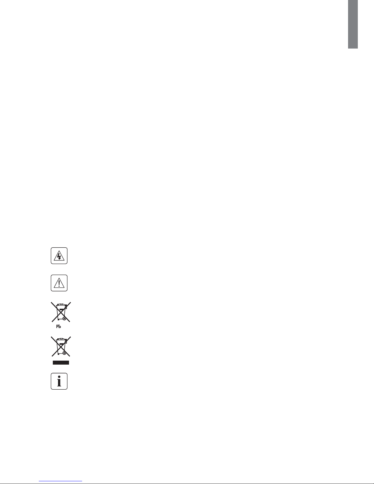
Special symbols
The following are examples of symbols used on the UPS or accessories to alert you to important
information:
RISK OF ELECTRIC SHOCK - Observe the warning associated with the risk of electric shock symbol.
Important instructions that must always be followed.
Do not discard the UPS or the UPS batteries in the trash.
This product contains sealed lead-acid batteries and must be disposed as stated in this manual.
For more information, contact your local recycling/reuse or hazardous waste center.
This symbol indicates that you should not discard waste electrical or electronic equipment (WEEE) in
the trash. For proper disposal, contact your local recycling/reuse or hazardous waste center.
Information, advice, help.
Page 4

4
881629-001
Personal safety
• The system has an internal battery as a backup power source. Consequently, the power outlets may be
energized even if the system is disconnected from the AC power source.
• Dangerous voltage levels are present within the system. The system should be opened exclusively by
qualifi ed service personnel.
• The system must be properly grounded.
• There are no user servicable parts inside the system, except for the replaceable battery.
• The battery supplied with the system contains small amounts of toxic materials.
• To avoid accidents, observe the following directives:
- Servicing of batteries should be performed or supervised by personnel knowledgeable about batteries
and the required precautions.
- When replacing batteries, replace with the same type and number of batteries or battery packs.
- Do not dispose of batteries in a fi re. The batteries might explode.
- Batteries constitute a danger (electrical shock, burns). The short-circuit current might be very high.
Precautions must be taken for all handling:
• Wear rubber gloves and boots.
• Do not lay tools or metal parts on top of batteries.
• Disconnect charging source prior to connecting or disconnecting battery terminals.
• Determine if the battery is inadvertently grounded. If inadvertently grounded, remove source from
ground. Contact with any part of a grounded battery can result in electrical shock. The likelihood of such
shock can be reduced if such grounds are removed during installation and maintenance (applicable to
equipment and remote battery supplies not having a grounded supply circuit).
Product safety
• The UPS connection instructions and operation described in this manual must be followed in order.
• A protection circuit breaker must be installed upstream and be easily accessible. The system can be
disconnected from the AC power source by opening this circuit breaker.
• Verify that the indications on the rating plate correspond to your AC powered system and to the actual
electrical consumption of all the equipment connected to the system.
• For pluggable equipment, the outlet shall be installed near the equipment and shall be easily accessible.
• Never install the system near liquids or in an excessively damp environment.
• Never let a foreign body penetrate inside the system.
• Never block the ventilation grates of the system.
• Never expose the system to direct sunlight or source of heat.
• If the system must be stored prior to installation, storage must be in a dry place.
• The admissible storage temperature range is -15°C to +50°C (5°F to 122°F).
• The system is not for use in a computer room as defi ned in the standard for the Protection of
Information Technology Equipment, ANSI/NFPA 75 (US installations only).
Contact Hewlett Packard Enterprise resellers to order a special battery kit, if needed to meet the
ANSI/NFPA 75 requirement.
Special precautions
• All handling operations require at least two people (unpacking, installation in rack system).
• Before and after the installation, if the UPS remains de-energized for a period of more than 6 months,
the UPS must be energized for a period of 24 hours, at least once every 6 months (for a normal storage
temperature less than 25°C/77°F). This charges the battery and avoids possible irreversible damage.
• During the replacement of the battery module, use the same type and number of elements as the
original battery module provided with the UPS to maintain an identical level of performance and safety.
In case of doubt, contact your Hewlett Packard Enterprise representative.
Page 5

5
881629-001
ENGLISH
Contents
Table of Contents
1. Introduction ...................................................................................................................6
1.1 Environmental protection ................................................................................................6
2. Presentation ..................................................................................................................7
2.1 Standard installations .....................................................................................................7
2.2 Rear panels .......................................................................................................................8
2.3 Control panel .................................................................................................................... 9
2.4 LCD description .............................................................................................................. 10
2.5 Display functions ........................................................................................................... 11
2.6 User settings .................................................................................................................. 11
3. Installation ..................................................................................................................13
3.1 Unpacking and contents verifi cation ............................................................................13
3.2 Battery module connection ........................................................................................... 14
4. Operation .....................................................................................................................15
4.1 Start-up and normal operation .....................................................................................15
4.2 Starting the UPS on battery ..........................................................................................15
4.3 UPS shutdown ...............................................................................................................15
4.4 Operation on battery power .........................................................................................15
4.5 Return of AC input power..............................................................................................16
4.6 UPS remote control functions ......................................................................................16
5. Maintenance ...............................................................................................................17
5.1 Troubleshooting .............................................................................................................17
5.2 Battery module replacement ........................................................................................18
5.3 Ordering Spares ............................................................................................................. 19
6. Technical specifications ..........................................................................................20
6.1 NA/JP technical specifi cations ......................................................................................20
6.2 INTL technical specifi cations ........................................................................................21
6.3 Glossary ..........................................................................................................................22
7. Support .........................................................................................................................23
7.1 Accessing Hewlett Packard Enterprise Support ........................................................... 23
7.2 Accessing updates ..........................................................................................................23
7.3 Customer self repair .......................................................................................................23
7.4 Remote support ..............................................................................................................24
7.5 Warranty information ..................................................................................................... 24
7.6 Regulatory information ..................................................................................................24
8. BSMI RoHS ..................................................................................................................25
Page 6

6
881629-001
1. Introduction
Thank you for selecting a Hewlett Packard Enterprise product to protect your electrical equipment.
The UPS (uninterruptible power system) range has been designed with the utmost care. Hewlett Packard
Enterprise recommends that you take the time to read this manual to take full advantage of the many
features of your UPS.
Before installing your UPS, read the booklet presenting the safety instructions. Then follow the instructions
in this manual.
To discover the entire range of products and options available, contact your Hewlett Packard Enterprise
representative or visit our web site at www.hpe.com/info/rackandpower.
1.1 Environmental protection
Hewlett Packard Enterprise has implemented an environmental-protection policy. Products are developed
according to an eco-design approach.
Substances
This product does not contain CFCs, HCFCs, or asbestos.
Packing
To improve waste treatment and facilitate recycling, separate the various packing components.
• The cardboard used is comprised of over 50% of recycled cardboard.
• Sacks and bags are made of polyethylene.
• Packing materials are recyclable and bear the appropriate identifi cation symbol
01
PET
.
Materials Abbreviations Number in the symbols
Polyethylene terephthalat PET 01
High-density polyethylene HDPE 02
Polyvinyl chloride PVC 03
Low-density polyethylene LDPE 04
Polypropylene PP 05
Polystyrene PS 06
Follow all local regulations for the disposal of packing materials.
End of life
Hewlett Packard Enterprise will process products at the end of their service life in compliance with local
regulations. Hewlett Packard Enterprise works with companies in charge of collecting and eliminating our
products at the end of their service life.
Product
The product is made up of recyclable materials.
Dismantling and destruction must take place in compliance with all local regulations concerning waste.
At the end of its service life, the product must be transported to a processing center for electrical and
electronic waste.
Battery
The product contains lead-acid batteries that must be processed according to applicable local regulations
concerning batteries.
The battery can be removed to comply with regulations and in view of correct disposal.
Page 7
7
881629-001
ENGLISH
2. Presentation
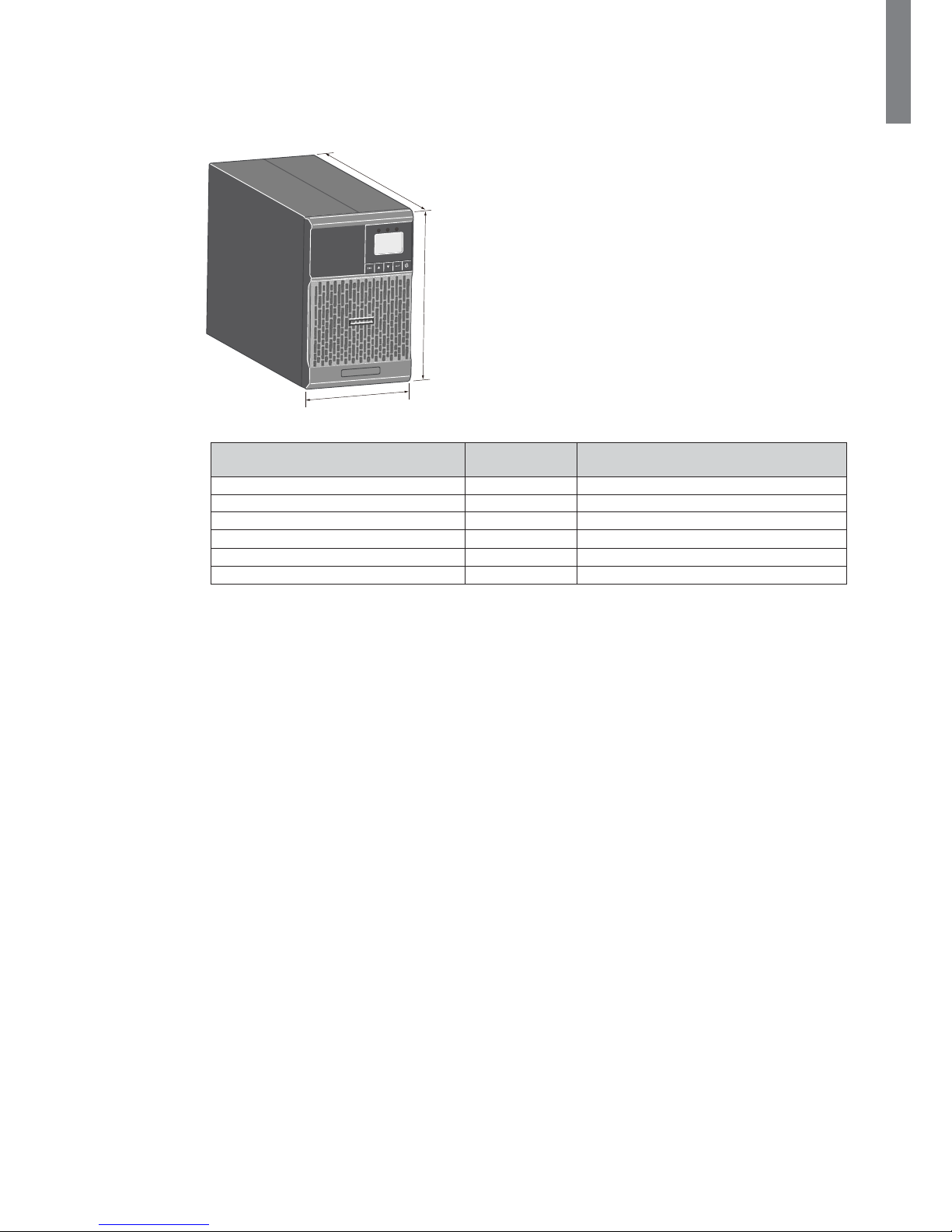
2.1 Standard installations
Tower models
Hewlett Packard Enterprise
D
H
W
Description Weights
(lb/kg)
Dimensions (in/mm)
D x W x H
HPE T750 G5 NA/JP Tower UPS 22.7 / 10.3 13.6 x 5.9 x 9.1 / 345 x 150 x 233
HPE T1000 G5 NA/JP Tower UPS
24.4 / 11.05 13.6 x 5.9 x 9.1 / 345 x 150 x 233
HPE T1500 G5 NA/JP Tower UPS 35.3 / 16.01 17.5 x 5.9 x 9.1 / 445 x 150 x 233
HPE T750 G5 INTL Tower UPS
21.9 / 9.9
13.6 x 5.9 x 9.1 / 345 x 150 x 233
HPE T1000 G5 INTL Tower UPS
35.2 / 15.9
17.5 x 5.9 x 9.1 / 445 x 150 x 233
HPE T1500 G5 INTL Tower UPS 35.2 / 15.9 17.5 x 5.9 x 9.1 / 445 x 150 x 233
Page 8
8
881629-001
2. Presentation
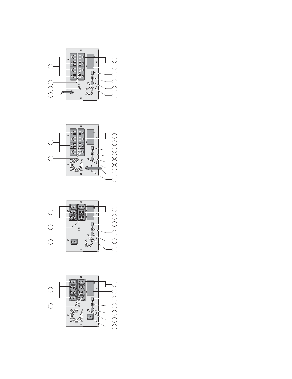
2.2 Rear panels
HPE T750/T1000 G5 NA/JP
8
5
2
1
4
6a
3
6b
7
9
HPE T1500 G5 NA/JP
5
2
1
4
6a
3
6b
7
8
9
HPE T750/T1000 G5 INTL
3
2
1
4
7
6a
6b
5
8
HPE T1500 G5 INTL
2
1
4
5
6a
3
6b
8
7
(1) USB communication port
(2) RS-232 communication port
(3) Slot for optional communication card
(4) Connector for ROO (remote ON/OFF)
or RPO (remote power OFF) control
(5) Outlets for connection of critical
equipment (Primary Group)
(6a) Group 1: programmable outlets for
connection of equipment
(6b) Group 2: programmable outlets for
connection of equipment
(7) Attached 6 ft input power cord for AC
power source (5-15P)
(8) LED indicating site wiring fault (SWF)
alarm
(9) Ground screw
(1) USB communication port
(2) RS-232 communication port
(3) Slot for optional communication card
(4) Connector for ROO (remote ON/OFF)
or RPO (remote power OFF) control
(5) Outlets for connection of critical
equipment (Primary Group)
(6a) Group 1: programmable outlets for
connection of equipment
(6b) Group 2: programmable outlets for
connection of equipment
(7) Socket for connection to AC power
source
(8) Ground screw
NOTE: The Hewlett Packard Enterprise Tower G5 UPSs have three
programmable output load segments. These are defined as Group
1, Group 2, and Primary Group. The load segments/groups can be
configured via software and the unit’s user interface. For advice on
configuration through software, see the HPEPP software or the UPS
Management Card documentation. To configure the UPS through
the front panel, see "2.6 User settings". Load Groups 1 and 2 can be
programmed to switch off/on independently. The Primary Load Group
controls the outlets indicated and initiates a unit shutdown. The Primary
Load Group is intended for the most critical loads.
Page 9

9
881629-001
ENGLISH
2. Presentation
2.3 Control panel
The UPS has a fi ve-button graphical LCD. It provides useful information about the UPS itself, load status,
events, measurements, and settings.
Power On
Indicator
(green)
On battery
Indicator
(yellow)
Alarm
Indicator (red)
Normal mode
100%
10min
100%
720W
800VA
Efficiency: ~98%
Escape Up Down Enter On/Off
button
The following table shows the indicator status and description:
Indicator Status Description
Green
On The UPS is operating normally.
Yellow
On The UPS is on Battery mode.
Red
On
The UPS has an active alarm or fault. For additional
information, see "5.1 Troubleshooting".
Page 10

10
881629-001
2. Presentation
2.4 LCD description
Operation Status
Load/Equipment Status
Normal mode
100%
10min
100%
720W
800VA
Efficiency: ~98%
Battery Status
Efficiency and Load Group Information
After 5 minutes of inactivity, the LCD displays the screen saver.
The backlight LCD automatically dims after 10 minutes of inactivity. Press any button to restore the screen.
The following table describes the status information provided by the UPS
NOTE: If another indicator appears, see "5.1 Troubleshooting" for additional information.
Operation status Possible cause Action
Standby mode
The UPS is OFF, waiting for start-up
command from user.
Equipment is not powered until the
button is pressed.
Normal mode
The UPS is operating normally. The UPS is powering and protecting
the equipment.
In AVR mode
No beep
The UPS is operating normally but
the utility voltage is outside Normal
mode thresholds.
The UPS is powering the
equipment through an Automatic
Voltage Regulation device.
The equipment is still normally
protected.
On Battery
Battery LED is on
1 beep every 10 seconds
A utility failure has occurred and
the UPS is in Battery mode.
The UPS is powering the equipment
with the battery power.
Prepare your equipment for
shutdown.
End of backup time
1 beep every 3 seconds
The UPS is in Battery mode and
the battery is running low.
This warning is approximate and
the actual time to shutdown may
vary significantly.
Depending on the UPS Load, the
"Battery Low" warning may occur
before the battery reaches 20%
capacity.
Page 11

11
881629-001
ENGLISH
2. Presentation
2.5 Display functions
Press the Enter ( ) button to activate the menu options. Use the two middle buttons ( and ) to scroll
through the menu structure. Press the Enter (
) button to select an option. Press the button to cancel
or return to the previous menu.
Menu map for display functions
Main Menu Submenu Display information or menu function
Measurements Load W VA / Load A pf / Output V Hz / Input V Hz /
Battery V min / Efficiency / Power usage
Control Load Segments Group 1: ON / OFF
Group 2: ON / OFF
These commands override user settings for load segments.
Start battery test Starts a manual battery test
Reset fault state Clears active faults (UPS restart required)
Restore factory settings Returns all settings to original values
Reset power usage
Clears power usage measurements
Settings Local settings Sets product general parameters
Input / output settings Sets input and output parameters
ON / OFF settings Sets ON / OFF conditions
Battery settings Sets battery configuration
Fault log Displays event log or alarms
Identification UPS Type / Part Number / Serial Number / Firmware release /
Com card address
2.6 User settings
The following table displays the options that can be changed by the user.
Description Available settings Default settings
Local Settings
Language [English] [Français] [Deutsch]
[Italiano] [Português] [Español]
[Русский]
Menus, status, notices and alarms,
UPS fault, Event Log data and
settings are in all supported
languages.
English
User selectable when
UPS is powered for the
first time.
LCD settings Modify LCD screen brightness and
contrast to adapt to room light
conditions.
Audible alarm Mode
[Enabled] [Disabled on battery] [Always
disabled]
Allows you to enable or disable the
audio alarm if an alarm occurs.
Enabled
Level
[High] [Low]
Allows you to set the audio alarm level
if an alarm occurs.
Low
In/Out Settings
Output voltage [100 V] [120 V] [125 V]
On INTL model: [200 V] [208 V]
[220 V] [230 V] [240 V]
User selectable when
UPS is
powered for the first
time.
Input thresholds [Normal mode] [Extended mode]
Extended mode reduces lower input
voltage to 70 V before UPS transfers
to battery.
This can be used if the load can
withstand low voltage supply.
Normal mode
Sensitivity [High] [Low]
High: For sensitive equipment. The
UPS transfers to battery when AC
utility conditions are poor.
Low: For equipment that can
withstand poor utility conditions.
The UPS does not transfer to battery
when AC utility conditions are poor.
High
Load segments - Auto
start delay
[No Delay] [1 s] [2 s]…[65354 s]
The connected load is powered after
the specified delay.
Group 1: 3 s
Group 2: 6 s
Page 12

12
881629-001
2. Presentation
Description Available settings Default settings
In/Out settings
Load segments - Auto
shutdown delay
[Disable] [0 s] [1 s] [2 s]…[65354 s]
During a power outage,
authorizes UPS to turn off power to
equipment connected to Group 1
and/or Group 2 outlets.
This feature allows the shedding of
non-critical loads in order to conserve
battery power for critical loads
connected to the Primary Group.
Group 1: Disable
Group 2: Disable
Overload
prealarm
[10 %] [15 %] [20 %] ... [100 %] [105 %]
Sets critical percentage of load where
alarm overload alarm occurs.
[105 %]
ON/OFF settings
Cold start [Disable] [Enable]
Enables the product to be started on
battery power.
First cold start is always disabled.
Enable
Forced reboot
[Disable] [Enable]
If AC power recovers during a
shutdown sequence:
- if enabled, shutdown sequence
completes and waits 10 seconds prior
to restart
- if disabled, shutdown sequence
does not complete and restart occurs
immediately.
Enable
Auto restart [Disable] [Enable]
Enables the product to restart
automatically when AC power
recovers after a complete battery
discharge.
Enable
Energy saving [Disable] [Enable]
If enabled, UPS shuts down after
5 minutes of backup time, if no load
is detected on the output.
Disable
Sleep mode [Disable] [Enable]
If disabled, LCD and communication
turn OFF immediately after UPS is
OFF.
If enabled, LCD and communication
stay ON for 1.5 hours after UPS is
OFF.
Disable
Remote command [Disable] [Enable]
If enabled, shutdown or restart
commands from software are
authorized.
Enable
RPO delay [0 s] [1 s] [2 s]...[180 s]
Delays remote power OFF command.
[0 s]
Battery settings
Automatic battery test [No test] [Every day] [Every week]
[Every month]
Available only if Battery Charge
mode is set to constant charge.
Every week
(in constant charge)
otherwise following
ABM
Low battery
warning
[1 %] [2 %] ... [100 %]
The alarm triggers when the set
percentage of battery capacity is
reached during a backup time.
20 %
Restart battery level
[1 %] [2 %] ... [100 %]
If set, automatic restart occurs only
when percentage of battery charge is
reached.
0 %
Battery charge mode [ABM cycling] [Constant charge] ABM cycling
Deep discharge protection [Yes] [No]
If set to Yes, the UPS automatically
prevents battery from deep discharge
by adapting end of backup time
voltage threshold.
Yes
Page 13

13
881629-001
ENGLISH
3. Installation
3.1 Unpacking and contents verification
(1) Tower UPS
(2) Quick start and safety instructions
(3) Two connection cables for the protected equipment
(4) RS-232 communication cable
(5) USB communication cable
Packing materials must be disposed of in compliance with all local regulations concerning waste.
Recycling symbols are printed on the packing materials to facilitate sorting.
H
ewle
t
t
P
ac
kard Enterprise
Page 14

14
881629-001
3. Installation
3.2 Battery module connection
CAUTION: Before starting the UPS, connect the internal battery.
NOTE: A small amount of arcing may occur when connecting the batteries.
This is normal and does not damage the UPS or present any safety concern.
Hewlett Packard Enterprise
A - Remove the front panel.
B - Connect the battery module.
Never pull on the wires.
C - Attach the front panel.
Page 15

15
881629-001
ENGLISH
4. Operation
4.1 Start-up and normal operation
To start the UPS:
1. Verify that the UPS power cord is plugged in.
The UPS front panel illuminates and shows the HPE logo.
2. Verify that the UPS status screen shows
.
3.Press the
button on the UPS front panel for at least 2 seconds.
The UPS front panel changes status to "UPS starting...".
4.
Chec
k the UPS front panel for active alarms or notices. Resolve any acti
ve alarms before
continuing. S
ee "5.1 Troubleshooting".
If the
indicator is on, do not proceed until all alarms are clear. Check the UPS status from the front
panel to view the acti
ve alarms. Correct the alarms and restart if necessary.
5. Verify that the
indicator illuminates solid, indicating that the UPS is operating normally and any loads
are powered and protected.
The UPS should be in Normal mode.
4.2 Starting the UPS on battery
Before using this feature, the UPS must have been powered by utility power with output enabled
at least once.
NOTE: Battery start can be disabled. See the "Cold start" setting in "ON/OFF settings".
To start the UPS on battery:
1.
P
ress the
button on the UPS front panel until the UPS front panel illuminates and shows
a status of "UPS star
ting...".
The UPS cycles through Standby mode to Bat
tery mode.
The
indicator illuminates solid.
The UPS supplies power to your equipment.
2.
Chec
k the UPS front panel for active alarms or notices other than the "Bat
tery mode" notice
and notices that indicate missing utility power
. Resolve any acti
ve alarms before continuing.
F
or more information, see "5.1 Troubleshooting".
4.3 UPS shutdown
To shut down the UPS:
Press the
button on the front panel for three seconds.
The UPS starts to beep and shows a status of "UPS shutting OFF...". The UPS then transfers to Standby
mode, and the
indicator turns off.
4.4 Operation on battery power
Transfer to battery power
• The connected devices continue to be supplied by the UPS when AC input power is no longer available.
The necessary energy is pro
vided by the battery.
• The
and indicators illuminate solid.
•
The audio alarm beeps every ten seconds.
The connected devices are supplied by the battery.
Page 16

16
881629-001
4. Operation
Low-battery warning
• The and indicators illuminate solid.
•
The audio alarm beeps every three seconds.
The remaining battery power is low. Shut down all applications on the connected equipment because
automatic UPS shutdown is imminent.
End of battery backup time
• The LCD displays "End of backup time."
•
The LEDs are no longer illuminated .
•
The audio alarms stops.
4.5 Return of AC input power
Following an outage, the UPS restarts automatically when AC input power returns (unless the restart
function is disabled) and the load is supplied again.
4.6 UPS remote control functions
The UPS offers a choice between two remote control functions.
• ROO: Remote ON/OFF allows remote action of the
button to shut down the UPS.
• RPO: Remote Power OFF allows a remote contact to be used to disconnect all the equipment connected
to the UPS. R
estarting the UPS requires manual intervention.
These functions are obtained by opening a contact connected between the appropriate connector pins (4) on
the rear panel of the UPS (see the following fi gure).
4
Remote control connection and test
1. Verify that the UPS is OFF and disconnected from the AC input source.
2.Remove connector (4).
3.
Connect a normally closed v
olt-free contact (60 Vdc / 30 Vac max, 20 mA max, 0.75 mm
2
(18 AWG) cable
cross-section) between the two connector pins (4) (see the following fi gures).
4
Contact open: UPS shutdown.
Contact closed: UPS startup (UPS connected to AC power and AC power is available).
NOTE: The local ON/OFF control using the button overrides the remote control function.
4
Contact open: UPS shutdown, LED illuminates.
T
o return to normal operation, deactivate the remote external contact and restart
the UPS by pressing the
button.
4.
Plug connector (4) into the bac
k of the UPS.
5.
Connect and restar
t the UPS (see "4.1 Start-up and normal operation").
6. Activate the external remote shutdown contact to test the function.
WARNING! This connector must only be connected to SELV (Safety Extra-Low Voltage) circuits.
Page 17

17
881629-001
ENGLISH
5. Maintenance
5.1 Troubleshooting
Operation status Possible cause Action
Batteries disconnected
The UPS does not recognize
the internal batteries.
If the condition persists, contact
your service representative.
The batteries are disconnected. Verify that all batteries are properly
connected. If the condition persists,
contact your service representative.
Overload
Power requirements exceed the
UPS capacity (greater than 105%
of nominal).
Remove some of the equipment
from the UPS. The UPS continues to
operate, but may shut down if
the load increases. The alarm resets
when the condition becomes
inactive.
End of battery life
The end of the battery life is
reached.
Contact your service representative
for battery replacement.
Event
A UPS event occurs.
Example:
Remote Power OFF, the RPO
contact is activated
to shut down the UPS and
prevent restart.
Set the contact back to its normal
position and press the
button
to restart.
UPS fault
The UPS has an internal fault. The UPS does not protect
the equipment anymore.
Note the alarm message and the
UPS Serial Number, then contact
your service representative.
Page 18

18
881629-001
5. Maintenance
5.2 Battery module replacement
Safety recommendations
The battery can cause electrocution and high short-circuit currents. The following safety precautions
are required before servicing the battery components:
• Remove watches, rings, bracelets, and all other metal objects from the hands and arms.
• Use tools with an insulated handle.
Battery tray removal
Enterprise
A
A - Remove the front panel.
B
B - Disconnect the battery module by
separating the connectors. Never pull
on the wires.
C
C - Remove the plastic protection cover
in front of the battery (one screw).
D
D - Pull the plastic tab to remove
the battery block and replace it.
Mounting the new battery module
Follow the previous instructions in reverse order.
• To ensure safety and high performance, use only batteries supplied by Hewlett Packard Enterprise.
• Take care to firmly press together the two parts of the connector during remounting.
Page 19

19
881629-001
ENGLISH
5. Maintenance
5.3 Ordering Spares
To order a spare, call Hewlett Packard Enterprise at 1-800-633-3600.
To replace parts under warranty, contact a Hewlett Packard Enterprise authorized service representative.
Item Spare part number
SPS-UPS T750 G5 NA/JP w/o battery 881759-001
SPS-UPS T750 G5 INTL w/o battery 881760-001
SPS-UPS T1000 G5 NA/JP w/o battery 881761-001
SPS-UPS T1000 G5 INTL w/o battery 881762-001
SPS-UPS T1500 G5 NA/JP w/o battery 881763-001
SPS-UPS T1500 G5 INTL w/o battery 881764-001
SPS-Battery T750 G5 UPS P02748-001
SPS-Battery T1000 G5 UPS P02749-001
SPS-Battery T1500 G5 UPS P02750-001
SPS-Accessories Tower G5 UPS WW P02751-001
Page 20

20
881629-001
6. Technical specifications
6.1 NA/JP technical specifications
Tower HPE T750 G5 NA/JP Tower HPE T1000 G5 NA/JP Tower HPE T1500 G5 NA/JP Tower
Output power @ 120 V
750 VA
600 W
1000 VA
770 W
1440 VA
1100 W
Output power @ 125 V
750 VA
600 W
1000 VA
770 W
1440 VA
1100 W
Output power @ 100 V
625 VA
500 W
833 VA
641 W
1080 VA
825 W
AC input power
• Rated input voltage Single phase 100–125 V
• Input voltage range
80 to 162 V
(1)
• Input frequency range
47 to 70 Hz (50 Hz system), 56.5 to 70 Hz (60 Hz system)
(2)
Output on battery power
• Voltage
100/120 V (-10%/+6%)
(3)
• Frequency 50/60 Hz ±0.1 Hz
Battery (sealed lead-acid, maintenance free)
• Standard 2 x 12 V
7 Ah
2 x 12 V
9 Ah
3 x 12 V
9 Ah
Environment
• Operating
temperature range
0°C to 35°C
(32°F to 95°F)
0°C to 40°C
(32°F to 104°F)
• Storage
temperature range
-15°C to +50°C
(5°F to 122°F)
• Relative humidity 20% to 90% (without condensation)
• Noise level <40 dBA
(1) The high and low thresholds can be adjusted using UPS settings.
(2) Up to 40 Hz in Low-Sensitivity mode (programmable using UPS settings).
(3) Adjustable to 100/120/125 V, must be set to the identical AC power source value.
CAUTION: To reduce the risk of fi re, connect only to a circuit provided with 20 amperes maximum branch
circuit overcurrent protection in accordance with the NEC (National Electric Code), ANSI/NFPA 70.
This product is designed for IT power distribution systems.
Filter
Transformer
"AVR"
Charger Inverter
Battery
Page 21

21
881629-001
ENGLISH
6. Technical specifications
6.2 INTL technical specifications
Tower HPE T750 G5 INTL Tower HPE T1000 G5 INTL Tower HPE T1500 G5 INTL Tower
Output power @ 230 V
750 VA
600 W
1000 VA
770 W
1440 VA
1100 W
Output power @ 208 V
750 VA
600 W
1000 VA
770 W
1440 VA
1100 W
Output power @ 200 V
625 VA
500 W
833 VA
641 W
1080 VA
825 W
AC input power
• Rated input voltage Single phase 200–240 V
• Input voltage range
160 to 294 V
(1)
• Input frequency range
47 to 70 Hz (50 Hz system), 56.5 to 70 Hz (60 Hz system)
(2)
Output on Battery Power
• Voltage
200/208/220/230/240 V (-10%/+6%)
(3)
• Frequency 50/60 Hz ±0.1 Hz
Battery (sealed lead-acid, maintenance free)
• Standard 2 x 12 V
7 Ah
2 x 12 V
9 Ah
3 x 12 V
9 Ah
Environment
• Operating
temperature range
0°C to 35°C
(32°F to 95°F)
0°C to 40°C
(32°F to 104°F)
• Storage
temperature range
-15°C to +50°C
(5°F to 122°F)
• Relative humidity 20% to 90% (without condensation)
• Noise level <40 dBA
(1) The high and low thresholds can be adjusted using UPS settings.
(2) Up to 40 Hz in Low-Sensitivity mode (programmable using UPS settings).
(3) Adjustable to 200/208/220/230/240 V, must be set to the identical AC power source value.
CAUTION: This UPS is rated for use on a circuit capable of delivering no more than 5 kRMS symmetrical
amperes, 240 V maximum.
When the appliance is used in EU areas, use an external circuit breaker in front of line with rating 16 A,
250 V which is IEC/EN 60898-1 standard compliant.
When the appliance is used in American areas, use an external circuit breaker in front of line with rating
20 A, 250 V.
This product is designed for IT power distribution systems.
Filter
Transformer
"AVR"
Charger Inverter
Battery
Page 22

22
881629-001
6. Technical specifications
6.3 Glossary
Backup time
Time during which the load can be supplied by the UPS operating on battery power.
Battery test
Internal UPS test to check battery status.
Cold start
The devices connected to the UPS can be started even if AC input power is not
available. The UPS operates on battery power alone.
Deep discharge
Battery discharge beyond the permissible limit, resulting in irreversible damage to
the battery.
Load
Devices or equipment connected to the UPS output.
Low-battery
warning
This is a battery voltage level indicating that battery power is low and that the user
must take action in light of the imminent break in the supply of power to the load.
Normal AC
input
The AC power line supplying the UPS under normal conditions.
Percent load
Ratio of the power effectively drawn by the load to the maximum output of the UPS.
Personalization
It is possible to modify certain UPS parameters set in the factory. Certain UPS
functions can also be modified by the software to better suit user needs.
Programmable
outlets
Controllable outlets for automatic load shedding, remote shutdown and sequential
restart (personalized using software).
UPS
Uninterruptible power system
UPS ON/OFF
controlled by
software
This function enables or disables initiation of UPS ON/OFF control sequences by
computer power management software.
Page 23

23
881629-001
ENGLISH
7. Support
7.1 Accessing Hewlett Packard Enterprise Support
• For live assistance, go to the Contact Hewlett Packard Enterprise Worldwide website
(www.hpe.com/assistance).
• To access documentation and support services, go to the Hewlett Packard Enterprise Support Center
website (www.hpe.com/support/hpesc).
Information to collect
• Technical support registration number (if applicable)
• Product name, model or version, and serial number
• Operating system name and version
• Firmware version
• Error messages
• Product-specifi c reports and logs
• Add-on products or components
• Third-party products or components
7.2 Accessing updates
• Some software products provide a mechanism for accessing software updates through the product
interface. Review your product documentation to identify the recommended software update method.
• To download product updates:
* Hewlett Packard Enterprise Support Center (www.hpe.com/support/hpesc)
* Hewlett Packard Enterprise Support Center: Software downloads
(www.hpe.com/support/downloads)
* Software Depot website (www.hpe.com/support/softwaredepot)
•
To subscribe to eNewsletters and alerts: www.hpe.com/support/e-updates.
• To view and update your entitlements, and to link your contracts and warranties with your profi le, go to
the Hewlett Packard Enterprise Support Center's "More Information on Access to HPE Support Materials"
page (www.hpe.com/support/AccessToSupportMaterials).
IMPORTANT: Access to some updates might require product entitlement when accessed through the Hewlett
Packard Enterprise Support Center. You must have an HPE Passport set up with relevant entitlements.
7.3 Customer self repair
Hewlett Packard Enterprise CSR (customer self repair) programs allow you to repair your product. If a CSR
part needs to be replaced, it will be shipped directly to you so that you can install it at your convenience.
Some parts do not qualify for CSR. Your Hewlett Packard Enterprise authorized service provider will
determine whether a repair can be accomplished by CSR.
For more information about CSR, contact your local service provider or go to the CSR website
(www.hpe.com/support/selfrepair).
Page 24

24
881629-001
7.4 Remote support
Remote support is available with supported devices as part of your warranty or contractual support
agreement. It provides intelligent event diagnosis, and automatic, secure submission of hardware event
notifi cations to Hewlett Packard Enterprise, which will initiate a fast and accurate resolution based on your
product's service level. Hewlett Packard Enterprise strongly recommends that you register your device for
remote support.
If your product includes additional remote support details, use the search function to locate that
information.
Remote support and Proactive Care information:
• HPE Get Connected (www.hpe.com/services/getconnected)
• HPE Proactive Care services (www.hpe.com/services/proactivecare)
• HPE Proactive Care service: Supported products list
(www.hpe.com/services/proactivecaresupportedproducts)
• HPE Proactive Care advanced service: Supported products list
(www.hpe.com/services/proactivecareadvancedsupportedproducts)
Proactive Care customer information Proactive
• Care central (www.hpe.com/services/proactivecarecentral)
• Proactive Care service activation (www.hpe.com/services/proactivecarecentralgetstarted)
7.5 Warranty information
To view the warranty for your product or to view the Safety and Compliance Information for Server,
Storage, Power, Networking, and Rack Products reference document, go to the Enterprise Safety and
Compliance website (www.hpe.com/support/Safety-Compliance-EnterpriseProducts).
Additional warranty information:
• HPE ProLiant and x86 Servers and Options (www.hpe.com/support/ProLiantServers-Warranties)
• HPE Enterprise Servers (www.hpe.com/support/EnterpriseServers-Warranties)
• HPE Storage Products (www.hpe.com/support/Storage-Warranties)
• HPE Networking Products (www.hpe.com/support/Networking-Warranties)
7.6 Regulatory information
To view the regulatory information for your product, view the Safety and Compliance Information for
Server, Storage, Power, Networking, and Rack Products, available at the Hewlett Packard Enterprise Support
Center (www.hpe.com/support/Safety-Compliance-EnterpriseProducts).
Additional regulatory information:
• Hewlett Packard Enterprise is committed to providing our customers with information about the
chemical substances in our products as needed to comply with legal requirements such as REACH
(Regulation EC No 1907/2006 of the European Parliament and the Council). A chemical information
report for this product can be found at:
* www.hpe.com/info/reach
• For Hewlett Packard Enterprise product environmental and safety information and compliance data,
including RoHS and REACH, see:
* www.hpe.com/info/ecodata
• For Hewlett Packard Enterprise environmental information, including company programs, product
recycling, and energy effi ciency, see:
* www.hpe.com/info/environment
7. Support
Page 25

25
881629-001
ENGLISH
8. BSMI RoHS
 Loading...