


R2200
Table of contents
 Loading...
HP R/T2200 UPS User Guide
October 2006 (Third Edition)
Part Number 404314-003

© Copyright 2006 Hewlett-Packard Development Company, L.P.
The information contained herein is subject to change without notice. The only warranties for HP products and services are set forth in the express
warranty statements accompanying such products and services. Nothing herein should be construed as constituting an additional warranty. HP
shall not be liable for technical or editorial errors or omissions contained herein.
October 2006 (Third Edition)
Part Number 404314-003
Audience assumptions
This guide is for the person who operates, configures, maintains, and troubleshoots UPSs. HP assumes
you are qualified in the servicing of high-voltage equipment and trained in recognizing hazards in
products with hazardous energy levels.

Contents
Component identification............................................................................................................... 6
UPS front panel......................................................................................................................................... 6
UPS front panel controls and LED indicators.................................................................................................. 7
UPS R/T2200 NA/JPN/TWN rear panel..................................................................................................... 8
UPS R/T2200 INTL rear panel .................................................................................................................... 9
REPO port .................................................................................................................................... 10
Installation ................................................................................................................................. 12
Precautions............................................................................................................................................. 12
Preparing to install the hardware............................................................................................................... 12
Required tools............................................................................................................................... 12
Selecting a site.............................................................................................................................. 13
Readying the equipment................................................................................................................. 13
Installing the UPS as a tower..................................................................................................................... 13
Installing the UPS in a rack ....................................................................................................................... 18
Connecting the batteries................................................................................................................. 21
Selecting the UPS voltage configuration............................................................................................ 22
Connecting the host computer ......................................................................................................... 23
Connecting the UPS to utility power .................................................................................................26
Connecting devices to the UPS ........................................................................................................26
Charging the UPS batteries............................................................................................................. 27
Powering up the UPS ..................................................................................................................... 27
Installing the ERM as a tower.................................................................................................................... 27
Installing the ERM in a rack ......................................................................................................................31
Connecting the ERM to the UPS....................................................................................................... 33
Attaching the RETMA rail covers...................................................................................................... 34
Charging the ERM batteries ............................................................................................................ 34
UPS operations........................................................................................................................... 35
Initiating a self-test................................................................................................................................... 35
Silencing an audible alarm....................................................................................................................... 35
Audible alarm conditions................................................................................................................ 35
Setting the power sensitivity adjustment dial................................................................................................ 35
Powering down the UPS........................................................................................................................... 36
Power management .................................................................................................................... 37
Power management software.................................................................................................................... 37
Maintenance.............................................................................................................................. 38
Updating the UPS firmware ...................................................................................................................... 38
Replacing the batteries............................................................................................................................. 38
Important battery safety information ................................................................................................. 38
Battery care and storage guidelines ................................................................................................. 39
UPS battery replacement procedure ................................................................................................. 39
Cleaning battery spills ............................................................................................................................. 41
Troubleshooting.......................................................................................................................... 42
UPS does not start ................................................................................................................................... 42
UPS does not communicate with the host computer ...................................................................................... 42
UPS firmware updating process is interrupted ............................................................................................. 42
Audible alarm sounds .............................................................................................................................. 42
Circuit breaker trips................................................................................................................................. 43
Contents 3

UPS operates on battery only.................................................................................................................... 43
UPS frequently switches between utility and battery power............................................................................ 43
UPS does not provide the expected backup time ......................................................................................... 43
UPS emits a slight clicking noise................................................................................................................ 43
Power LED flashes ................................................................................................................................... 43
Voltage Configuration LED is green ........................................................................................................... 44
Output Load Level LED is red or flashing red ............................................................................................... 44
Battery Charge LED is red......................................................................................................................... 44
Specifications............................................................................................................................. 45
UPS physical specifications....................................................................................................................... 45
ERM physical specifications...................................................................................................................... 45
UPS input specifications ...........................................................................................................................45
UPS output specifications.......................................................................................................................... 46
Power protection specifications ....................................................................................................... 46
Voltage specifications ....................................................................................................................46
Output tolerance specifications........................................................................................................ 46
Output feature specifications........................................................................................................... 46
Battery specifications ............................................................................................................................... 47
Battery runtime........................................................................................................................................ 47
Environmental specifications ..................................................................................................................... 47
Spares....................................................................................................................................... 48
Ordering spares...................................................................................................................................... 48
Spare parts list........................................................................................................................................ 48
Hardware options ...................................................................................................................................48
Technical support........................................................................................................................ 49
Before you contact HP.............................................................................................................................. 49
HP contact information............................................................................................................................. 49
Warranty information.................................................................................................................. 50
Limited warranty ..................................................................................................................................... 50
$250,000 Computer Load Protection Guarantee......................................................................................... 50
Pre-Failure Battery Warranty ..................................................................................................................... 50
Regulatory compliance notices ..................................................................................................... 52
Regulatory compliance identification numbers............................................................................................. 52
Federal Communications Commission notice............................................................................................... 52
FCC rating label............................................................................................................................ 52
Class A equipment......................................................................................................................... 53
Class B equipment......................................................................................................................... 53
Declaration of conformity for products marked with the FCC logo, United States only....................................... 53
Modifications.......................................................................................................................................... 54
Cables................................................................................................................................................... 54
Canadian notice (Avis Canadien).............................................................................................................. 54
European Union regulatory notice .............................................................................................................54
Disposal of waste equipment by users in private households in the European Union......................................... 55
Japanese notice ...................................................................................................................................... 55
BSMI notice............................................................................................................................................ 55
Korean notice ......................................................................................................................................... 56
Battery replacement notice........................................................................................................................ 56
Power cord statement for Japan................................................................................................................. 56
Electrostatic discharge................................................................................................................. 57
Contents 4

Preventing electrostatic discharge.............................................................................................................. 57
Grounding methods to prevent electrostatic discharge.................................................................................. 57
Acronyms and abbreviations........................................................................................................ 58
Index......................................................................................................................................... 59
Contents 5
Component identification
In this section
UPS front panel........................................................................................................................................ 6
UPS front panel controls and LED indicators ................................................................................................ 7
UPS R/T2200 NA/JPN/TWN rear panel ................................................................................................... 8
UPS R/T2200 INTL rear panel................................................................................................................... 9
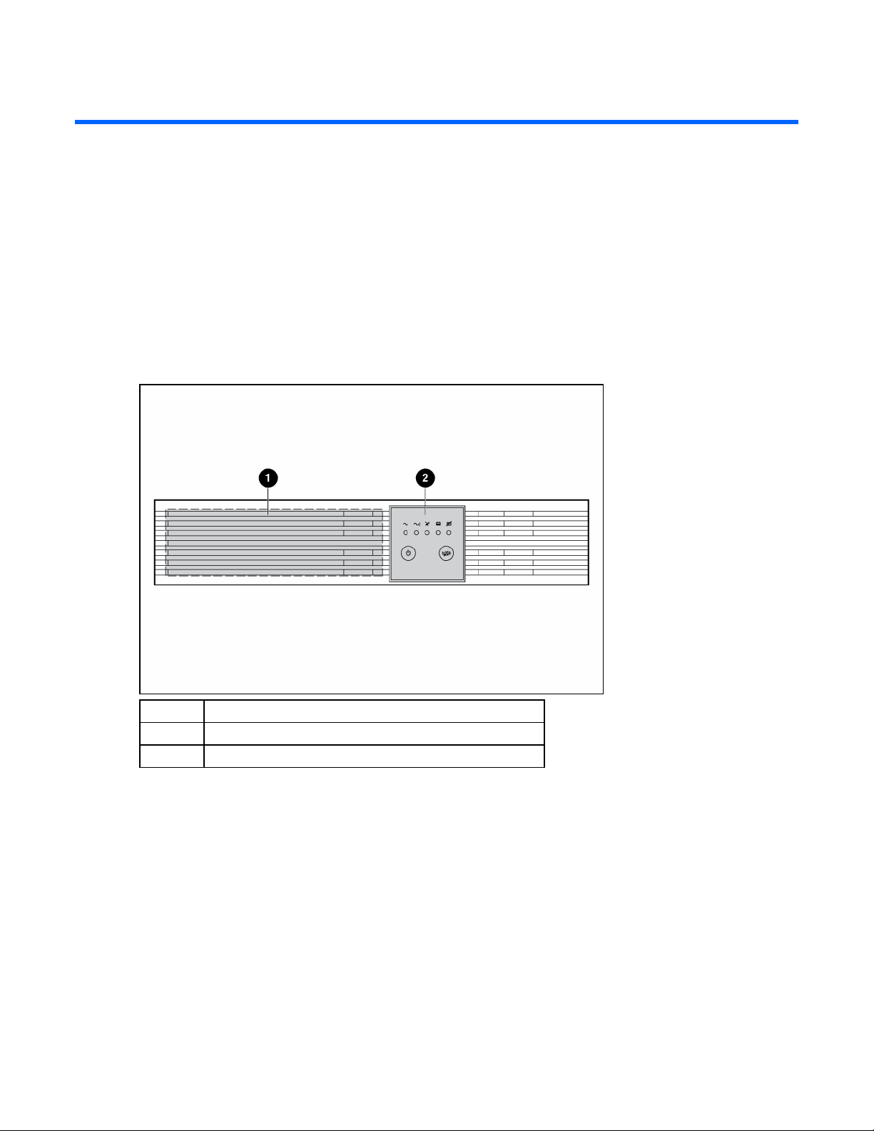
UPS front panel
Item Description
1 Battery compartment
2 Control buttons and LED display
Component identification 6
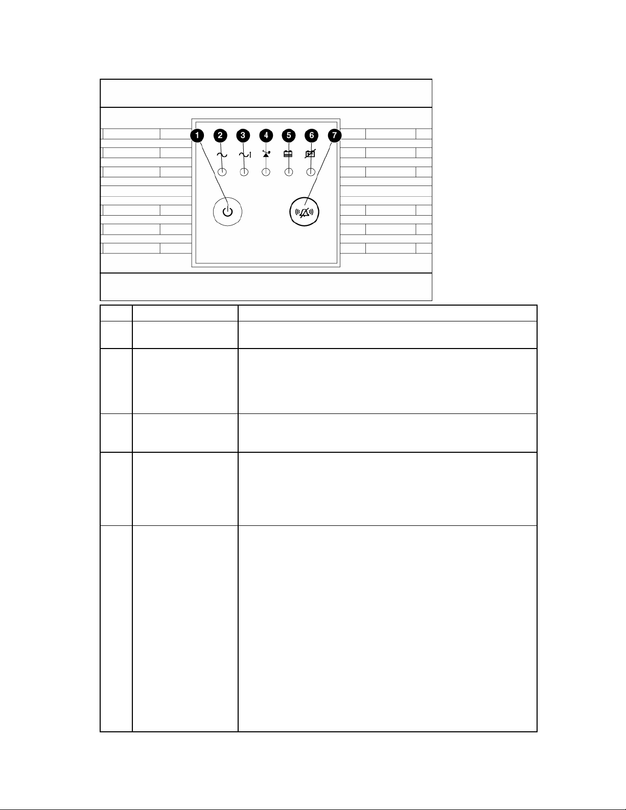
UPS front panel controls and LED indicators
Item Description Function
1
2 Power LED
3 Voltage Correction LED
4 Output Load Level LED
5 Battery Charge LED
Power On/Standby
button
Turns the UPS power on and off, and places the UPS in Standby mode.1
Green—The UPS is on and supplying connected equipment with AC
power.
Flashing green—The UPS is operating from its internal batteries during a
blackout or severe brownout. If the blackout or brownout is prolonged,
save any open files and shut down the connected equipment.
Green—The UPS is automatically correcting high or low AC voltage on
the utility line without the assistance of battery power. The UPS will emit a
slight clicking noise.
Shows approximately how much of the UPS power capacity is used to
support the equipment connected to the output receptacles.
Red—Maximum load
Amber—Medium load
Green—Light load
When the UPS is operating from utility power (the Power LED is green),
the Battery Charge LED indicates the approximate charge state of the
batteries:
• Red—The batteries are beginning to charge.
• Amber—The batteries are midway through charging.
• Green—The batteries are fully charged.
When the UPS is operating on battery power during a blackout or severe
brownout (the Power LED is flashing green), the Battery Charge LED
indicates the approximate amount of remaining battery energy:
• Red—The batteries have a low level of energy.
• Amber—The batteries have a medium amount of energy.
• Green—The batteries have a high amount of energy.
Periodically initiate a self-test ("Initiating a self-test" on page 35) to
determine the energy level of the batteries before a blackout or brownout
occurs.
Component identification 7
Item Description Function
6 Battery Warning LED
Red—During a self-test, the UPS found that the batteries must be
recharged. Charge the batteries and repeat the self-test ("Initiating a self-
test" on page 35).
7 Mute/Test button
Silences UPS alarms and initiates a self-test ("Initiating a self-test" on
page 35).
1
IMPORTANT: While in Standby mode, the UPS maintains the charge on the batteries, but no power is
available at the output receptacles. The UPS remains in Standby mode until an alternate mode is selected or
until utility power is removed.
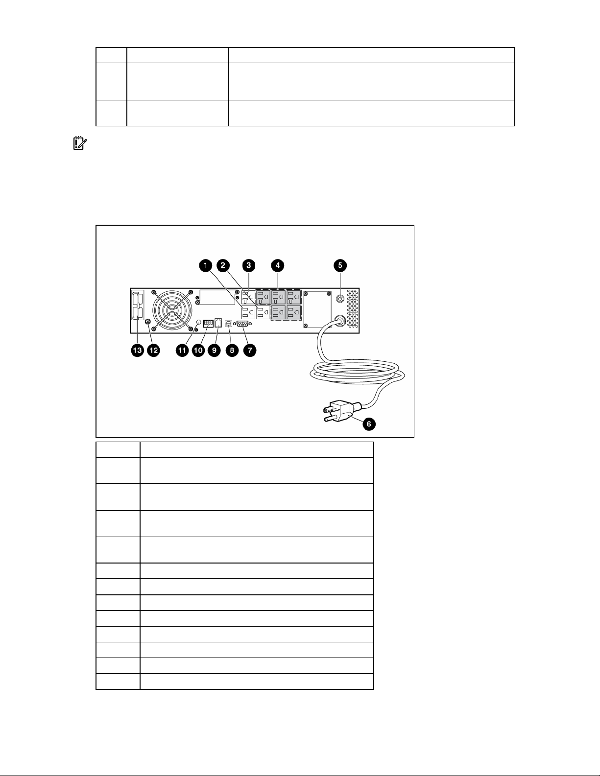
UPS R/T2200 NA/JPN/TWN rear panel
Item Description
1
Load segment 1 (one NEMA 5-15 output receptacle for
surge and battery backup protection)
2
Load segment 2 (one NEMA 5-15 output receptacle for
surge and battery backup protection)
3
Load segment 3 (one NEMA 5-20 output receptacle for
surge and battery backup protection)
4
Load segment 4 (five unswitchable NEMA 5-15/20 output
receptacles for surge and battery backup protection)
5 Input circuit breaker
6 Input power cord with NEMA 5-20 plug
7 Serial communications port
8 USB communications port
9 REPO port
10 Voltage configuration and charge rate DIP switches
11 Power sensitivity adjustment dial
12 Ground bonding screw
Component identification 8
Item Description
13 ERM connector
For information about controlling load segments remotely, see "Power management software (on page
37)."
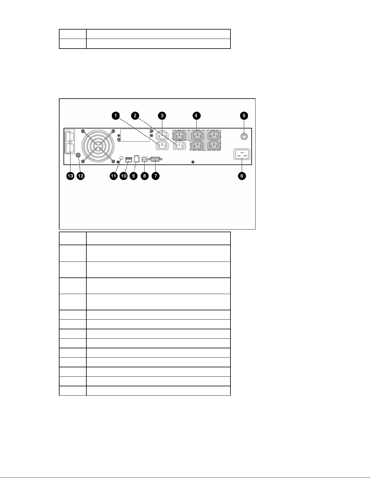
UPS R/T2200 INTL rear panel
Item Description
1
Load segment 1 (one IEC-320-C13 output receptacle for
surge and battery backup protection)
2
Load segment 2 (one IEC-320-C13 output receptacle for
surge and battery backup protection)
3
Load segment 3 (one IEC-320-C13 output receptacle for
surge and battery backup protection)
4
Load segment 4 (five unswitchable IEC-320-C13 output
receptacles for surge and battery backup protection)
5 Input circuit breaker
6 Input power cord with IEC-320-C20 plug
7 Serial communications port
8 USB communications port
9 REPO port
10 Voltage configuration and charge rate DIP switches
11 Power sensitivity adjustment dial
12 Ground bonding screw
13 ERM connector
For information about controlling load segments remotely, see "Power management software (on page
37)."
Component identification 9
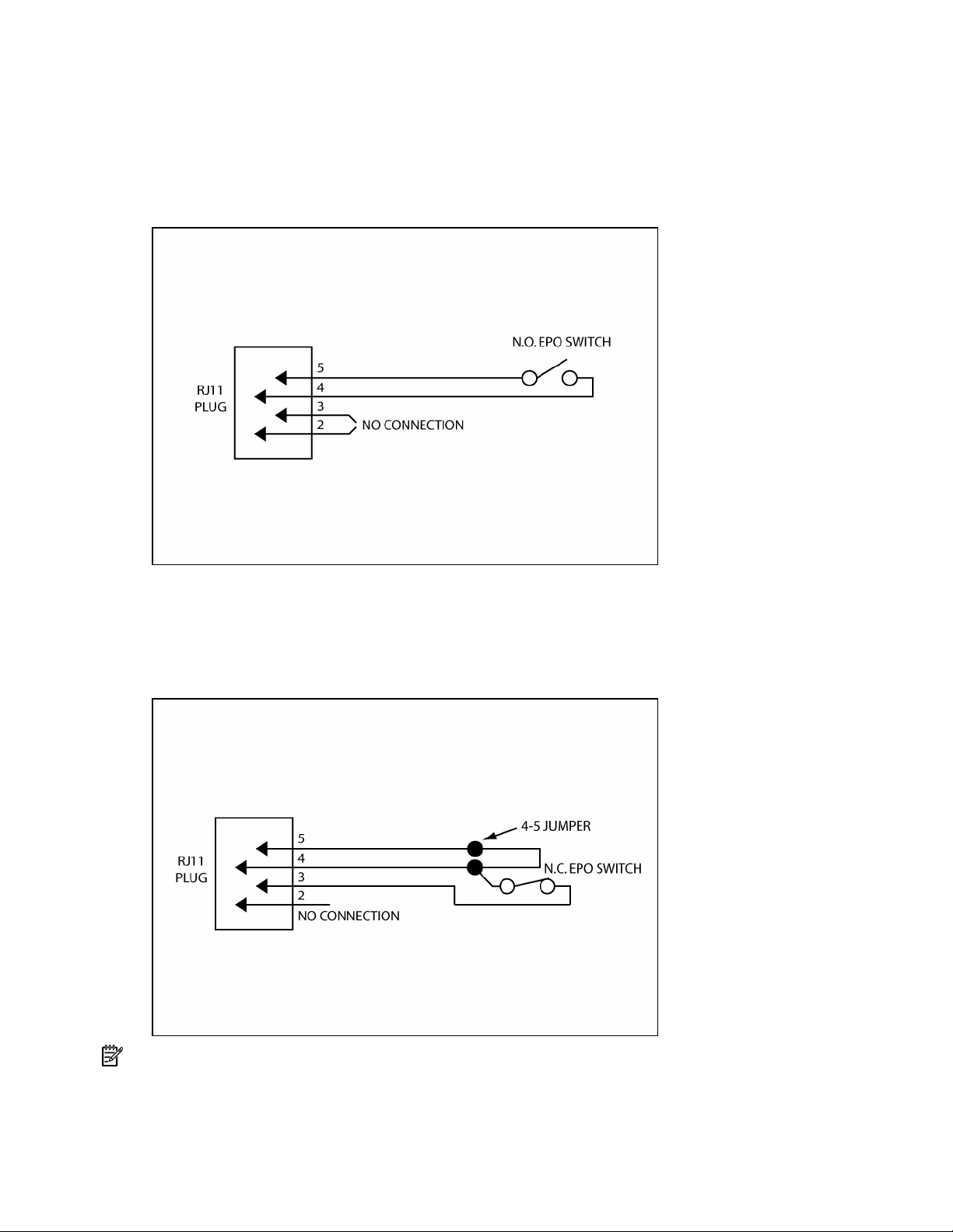
REPO port
The UPS includes an RJ-11 type EPO port. The EPO function can be used to power down the UPS output
receptacles in an emergency. This feature is enabled by utilizing a normally open (N.O.) switch (option 1)
or a normally closed (N.C.) switch (option 2). The EPO port is referred to as a REPO port when used in
conjunction with a remote main disconnect device that shuts down utility power in an emergency.
Option 1: User supplied normally open switch
When the switch is enabled:
• The REPO feature immediately powers down protected devices and does not utilize the orderly
shutdown procedure initiated by power management software.
• The REPO feature shuts down UPS units operating under either utility or battery power.
Option 2: User supplied normally closed switch
NOTE: If the UPS was operating on battery power when the remote switch was closed, no power is
available to the load devices until utility power is restored and the UPS has been manually powered up.
Component identification 10

To restore power to the load devices after the REPO feature is activated, press the Power On/Standby
button after the AC source is reconnected to the UPS.
IMPORTANT: Pressing and holding the Power On/Standby button without utility present normally initiates
a battery start and the UPS assumes the load. However, if the Power On/Standby button is pressed and a
REPO is detected, battery start is inhibited and the UPS is not able to assume the load.
To power down the entire network in the event of an emergency, the REPO ports of multiple UPS units can
be connected to a single switch.
Component identification 11

Installation
In this section
Precautions............................................................................................................................................ 12
Preparing to install the hardware ............................................................................................................. 12
Installing the UPS as a tower.................................................................................................................... 13
Installing the UPS in a rack...................................................................................................................... 18
Installing the ERM as a tower................................................................................................................... 27
Installing the ERM in a rack ..................................................................................................................... 31
Precautions
Save these instructions. This document contains important safety instructions that should be followed
during installation, operation, and maintenance of the UPS and batteries.
WARNING: A risk of personal injury from electric shock and hazardous energy levels
exists. The installation of options and routine maintenance and service of this product
must be performed by individuals who are knowledgeable about the procedures,
precautions, and hazards associated with AC power products.
WARNING: To prevent personal injury from earth conductor leakage current:
• Do not operate the UPS while disconnected from the utility power source.
• Disconnect load devices before disconnecting the UPS from the utility power source.
WARNING: To prevent personal injury, prepare the area and observe all materials
handling procedures when transporting the UPS. When fully assembled, the UPS weighs
29 kg (64 lb).
WARNING: To prevent personal injury, prepare the area and observe all materials
handling procedures when transporting the ERM. When fully assembled, the ERM weighs
28.6 kg (63 lb).
Preparing to install the hardware
Before installing the hardware:
1. Be sure the necessary tools and materials ("Required tools" on page 12) are available.
2. Select an installation site ("Selecting a site" on page 13).
3. Prepare the equipment ("Readying the equipment" on page 13) for installation in the rack.
Required tools
• No. 2 Phillips screwdriver
• T-20 Torx screwdriver
Installation 12

Selecting a site
WARNING: To prevent fire or electric shock, install the unit in a temperature- and
humidity-controlled indoor environment, free of conductive contaminants.
When selecting a site, consider the following factors:
• Elevated operating ambient temperature—If the equipment is installed in a closed or multi-unit rack
assembly, the operating ambient temperature of the rack environment might be greater than room
ambient temperature. Install the equipment in an environment compatible with the operating
temperature ("Environmental specifications" on page 47).
• Reduced air flow—In the rack, the rate of air flow required for safe operation of the equipment must
not be compromised.
• Circuit overloading—Consideration should be given to the connection of the equipment to the supply
circuit and the effect that overloading of the circuits might have on overcurrent protection and supply
wiring. Appropriate consideration of equipment nameplate ratings should be used when addressing
this concern.
• Reliable earthing—Reliable earthing of rack-mounted equipment should be maintained. Particular
attention should be given to supply connections other than direct connections to the branch circuit,
such as the use of power strips.
• Electrical requirements—All models require a dedicated (unshared) branch circuit, suitably rated for
the specific UPS as stated in "Input specifications ("UPS input specifications" on page 45)" .
Readying the equipment
1. Check the battery recharge date specified on the label that is affixed to the shipping carton.
IMPORTANT: Do not use the battery if the recharge date has passed. If the date on the battery recharge
date label has passed without the battery being recharged, contact an HP authorized service representative
for directions.
2. Transport the packaged unit to its installation location.
3. Unpack the equipment near the rack where the unit will be assembled.
CAUTION: Always plan the rack installation so that the heaviest item is on the bottom of the rack. Install
the heaviest item first, and continue to populate the rack from the bottom to the top.
Installing the UPS as a tower
Before installing the unit, review and adhere to all warnings provided in "Precautions (on page 12)."
Installation 13
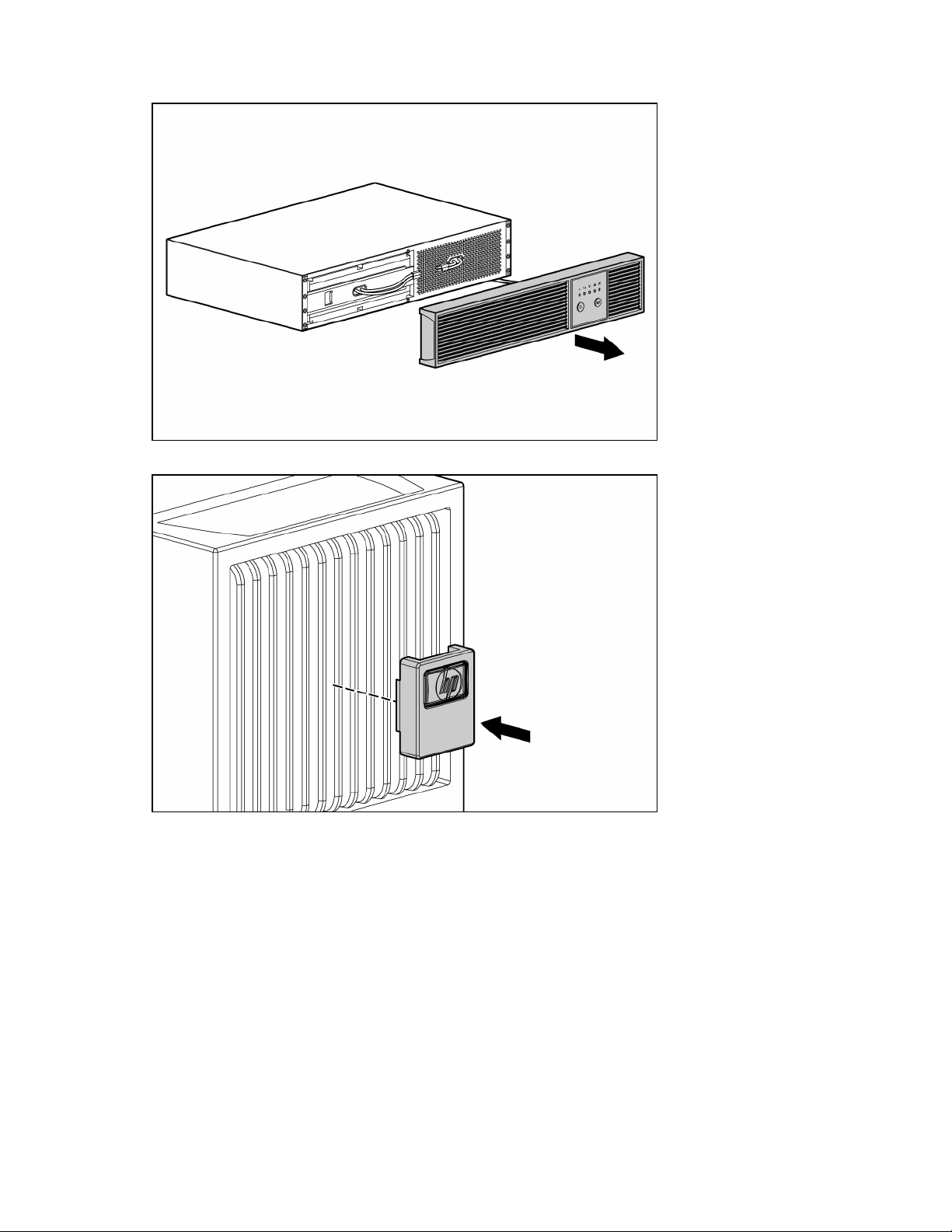
Remove the UPS front bezel.
1.
2. Attach the logo badge above the LED/Control panel.
Installation 14
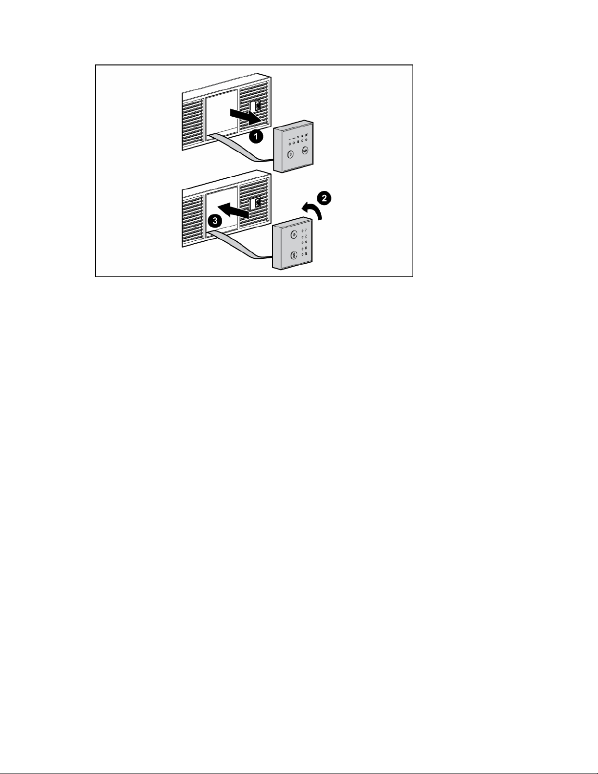
From inside the bezel, gently push out the LED/Control panel and rotate 90 degrees.
3.
4. Replace the front bezel.
Installation 15
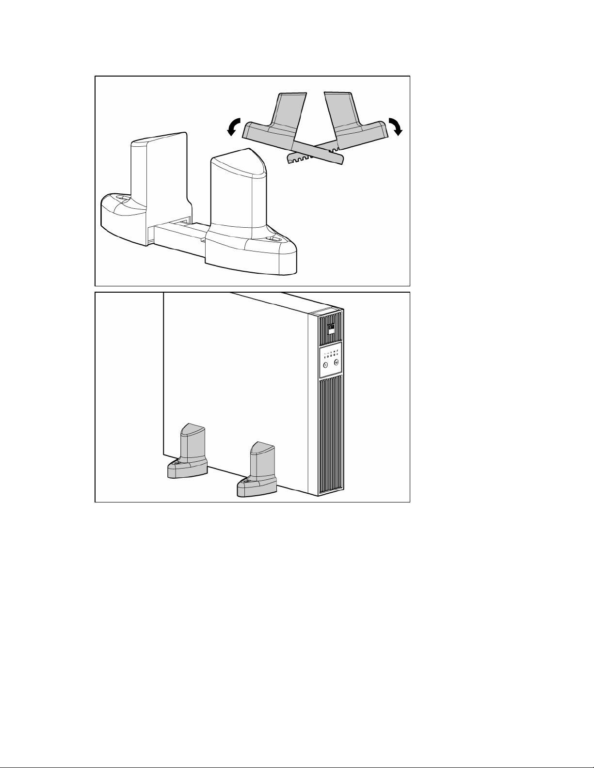
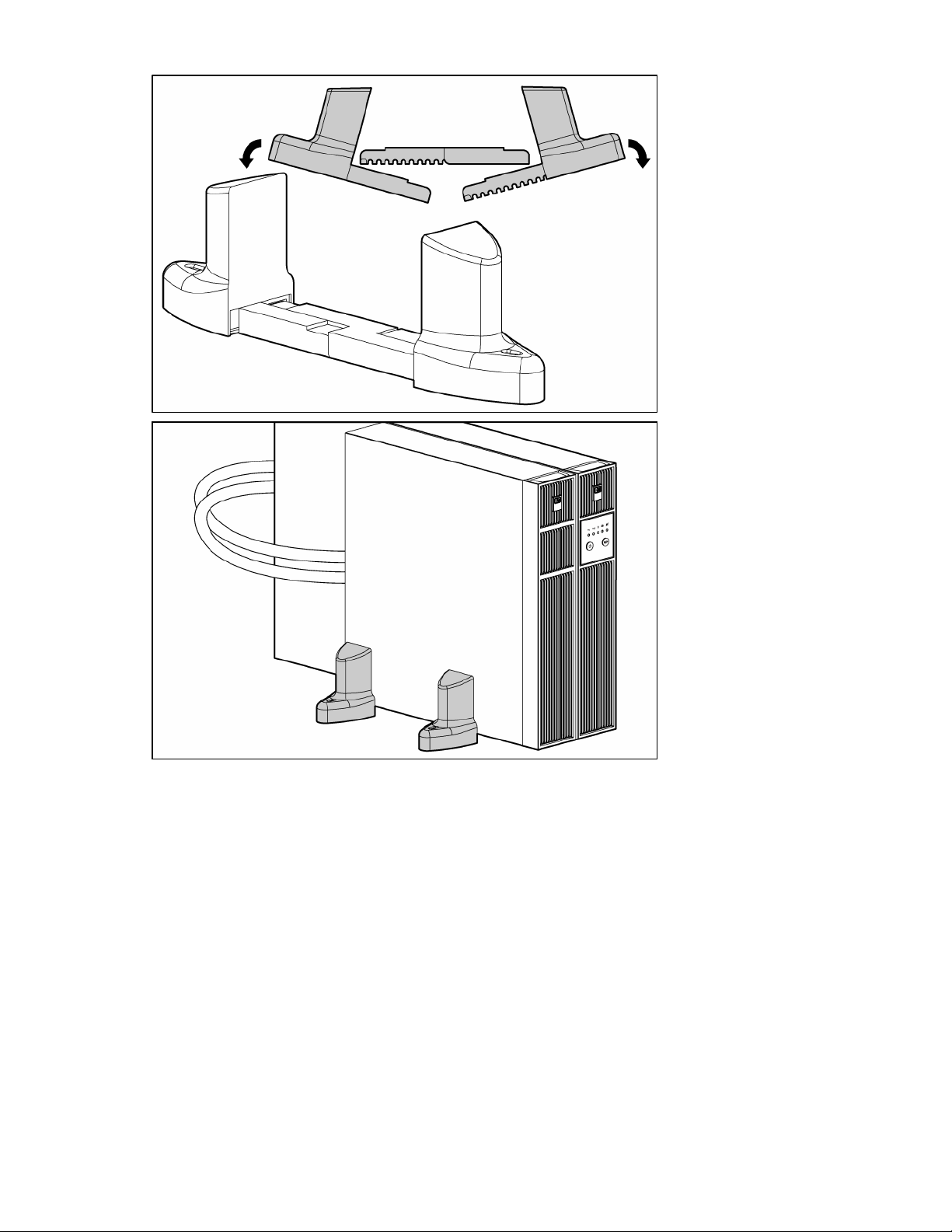
Stand the unit on its side with the LED/Control panel at the top. Extend the tower stand to fit any
5.
configuration from 1U to 9U.
Installation 16
Installation 17
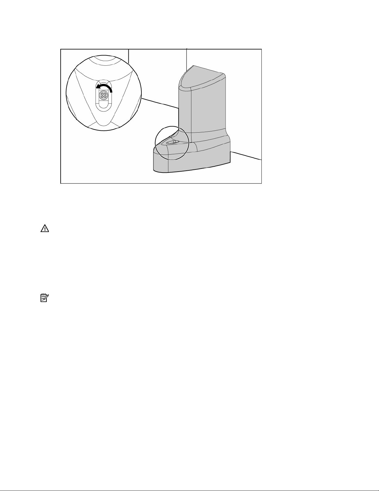
Adjust the fine adjustment screws to ensure the tower stands fit securely around the UPS and/or
6.
ERM.
Installing the UPS in a rack
Before installing the unit, review and adhere to all warnings provided in "Precautions (on page 12)."
WARNING: To reduce the risk of personal injury or damage to the equipment, be sure
that:
• The leveling feet are extended to the floor.
• The full weight of the rack rests on the leveling feet.
• The stabilizing feet are attached to the rack if it is a single-rack installation.
• The racks are coupled together in multiple-rack installations.
• Only one component is extended at a time. A rack may become unstable if more than
one component is extended for any reason.
NOTE: Mounting hardware for square- and round-holed racks is included in the UPS kit.
Installation 18
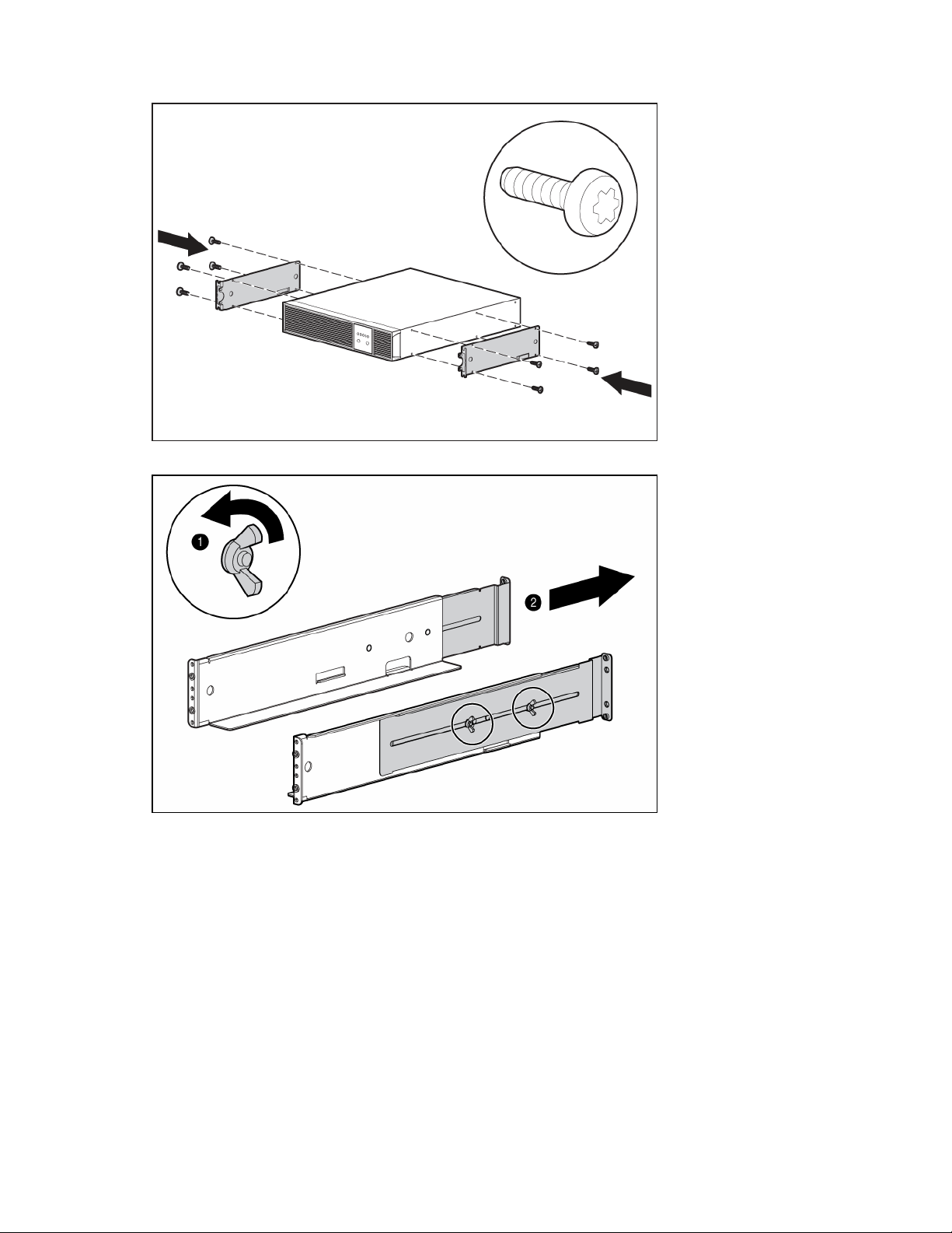
Attach the 2U side-mounting brackets to the unit.
1.
2. Loosen the wing nuts, and extend the brackets to the desired length.
Installation 19
Loading...