

Page 1

HP Tower UPS
User Guide
Abstract
This document is for the person who installs and maintains HP UPS products. HP assumes you are qualified
in the installation of electrical equipment and trained in recognizing hazards in products with hazardous
energy levels.
Part Number: 792523-001
November 17, 2014
Edition: 1
Page 2

Page 2
792523-001 Edition 1
ENGLISH
Special Symbols
The following are examples of symbols used on the UPS or accessories to alert you to important
information:
RISK OF ELECTRIC SHOCK - Observe the warning associated with the risk of electric shock symbol.
Important instructions that must always be followed.
Do not discard the UPS or the UPS batteries in the trash.
This product contains sealed lead acid batteries and must be disposed as it's explain in this manual.
For more information, contact your local recycling/reuse or hazardous waste center.
This symbol indicates that you should not discard waste electrical or electronic equipment (WEEE)
in the trash. For proper disposal, contact your local recycling/reuse or hazardous waste center.
IMPORTANT SAFETY INSTRUCTIONS
SAVE THESE INSTRUCTIONS. This manual contains important instructions
that should be followed during installation and maintenance of the UPS and batteries.
The Tower UPS models that are covered in this manual are intended for installation in an environment
within 0 to 40°C/32 to 100°F, free of conductive contaminant.
For all models:
• FCC/EN55022 Class B IEC62040-2 C1
Certication Standards
• UPS directives: UL 1778 4th edition (UL listed).
• Performance: IEC 62040-3: 2001.
• Radiated emission: FCC CFR 47 part 15 subpart B, Class B, VCCI.
• Surges withstand ability: IEEE ANSI C62.41 Category A2 (UL Listed).
Regulatory Notices
See HP EG regulatory notices at http://www.hp.com/support/Safety-Compliance-EnterpriseProducts.
Page 3

792523-001 Edition 1
Page 3
ENGLISH
Personal Safety
• The system has an internal battery as a backup power source. Consequently, the power outlets may be energized,
even if the system is disconnected from the AC power source.
• Dangerous voltage levels are present within the system. It should be opened exclusively by qualied
service personnel.
• The system must be properly grounded.
• There are no user serviceable parts inside except for the replaceable battery.
• The battery supplied with the system contains small amounts of toxic materials.
• To avoid accidents, the directives listed below must be observed:
- Servicing of batteries should be performed or supervised by personnel knowledgeable about batteries and the
required precautions.
- When replacing batteries, replace with the same type and number of batteries or battery packs.
- Do not dispose of batteries in a re. The batteries may explode.
- Batteries constitute a danger (electrical shock, burns). The short-circuit current may be very high.
Precautions must be taken for all handling:
• Wear rubber gloves and boots.
• Do not lay tools or metal parts on top of batteries.
• Disconnect charging source prior to connecting or disconnecting battery terminals.
• Determine if battery is inadvertently grounded. If inadvertently grounded, remove source from ground.
Contact with any part of a grounded battery can result in electrical shock. The likelihood of such shock
can be reduced if such grounds are removed during installation and maintenance (applicable to
equipment and remote battery supplies not having a grounded supply circuit).
Product Safety
• The UPS connection instructions and operation described in the manual must be followed in
the indicated order.
• A protection circuit breaker must be installed upstream and be easily accessible.
The system can be disconnected from the AC power source by opening this circuit breaker.
• Check that the indications on the rating plate correspond to your AC powered system and to
the actual electrical consumption of all the equipment to be connected to the system.
• For PLUGGABLE EQUIPMENT, the outlet shall be installed near the equipment and shall
be easily accessible.
• Never install the system near liquids or in an excessively damp environment.
• Never let a foreign body penetrate inside the system.
• Never block the ventilation grates of the system.
• Never expose the system to direct sunlight or source of heat.
• If the system must be stored prior to installation, storage must be in a dry place.
• The storage temperature range is -15 to +40ºC/5 to 104°F.
• The system is not for use in a computer room AS DEFINED IN the standard for the Protection
of Information Technology Equipment, ANSI/NFPA 75 (US installations only).
Special Precautions
• All handling operations will require at least two people (unpacking, installation in rack system).
• Before and after the installation, if the UPS remains de-energized for a long period, the UPS must be
energized for a period of 24 hours, at least once every 6 months (for a normal storage temperature
less than 25°C/77°F). This charges the battery, thus avoiding possible irreversible damage.
• During the replacement of the battery module, it is imperative to use the same type and number of
element as the original battery module provided with the UPS to maintain an identical level of
performance and safety. For questions, contact your HP representative.
Important: Replace the battery module with the same type battery module, available from HP.
Page 4

Page 4
792523-001 Edition 1
ENGLISH
Contents
Table of Contents
Contents .....................................................................................................................................4
1. Overview ............................................................................................................................... 5
1.1 Environmental protection ....................................................................................................................................... 5
1.2 Weights and dimensions .......................................................................................................................................... 6
1.3 Rear panels .................................................................................................................................................................... 6
2. User Interface ......................................................................................................................8
2.1 Control panel ................................................................................................................................................................ 8
2.2 LCD window .................................................................................................................................................................. 8
2.3 UPS setting through the LCD ..................................................................................................................................9
3. Installation ......................................................................................................................... 10
3.1 Unpacking and contents check ...........................................................................................................................10
3.2 Battery module connection .................................................................................................................................. 10
3.3 Communication ports ............................................................................................................................................11
3.4 Ground connection ..................................................................................................................................................11
4. Operation ........................................................................................................................... 12
4.1 Start-up and normal operation ............................................................................................................................12
4.2 Starting the UPS on battery .................................................................................................................................. 12
4.3 UPS shutdown ............................................................................................................................................................12
4.4 Operation on battery power .................................................................................................................................12
4.5 Return of AC input power ......................................................................................................................................12
5. Maintenance ..................................................................................................................... 13
5.1 Troubleshooting ........................................................................................................................................................13
5.2 Updating the UPS rmware ..................................................................................................................................13
5.3 Battery module replacement ...............................................................................................................................13
5.4 Spares ............................................................................................................................................................................15
6. Technical Specications ................................................................................................ 16
6.1 HP T750 G4 NA/JP UPS, HP T1000 G4 NA/JP UPS, and HP T1500 G4 NA/JP UPS ..............................16
6.2 HP T750 G4 INTL UPS, HP T1000 G4 INTL UPS, and HP T1500 G4 INTL UPS ......................................... 17
7. Support and other resources ...................................................................................... 18
Page 5
792523-001 Edition 1
Page 5
ENGLISH
1. Overview
Save these instructions. This document contains important safety instructions that should be followed during installation,
operation, and maintenance of the UPS and batteries.
1.1 Environmental protection
Products are developed according to an eco-design approach.
Substances
This product does not contain CFCs, HCFCs, or asbestos.
Packing
To improve waste treatment and facilitate recycling, separate the various packing components.
• The cardboard we use comprises over 50% of recycled cardboard.
• Sacks and bags are made of polyethylene.
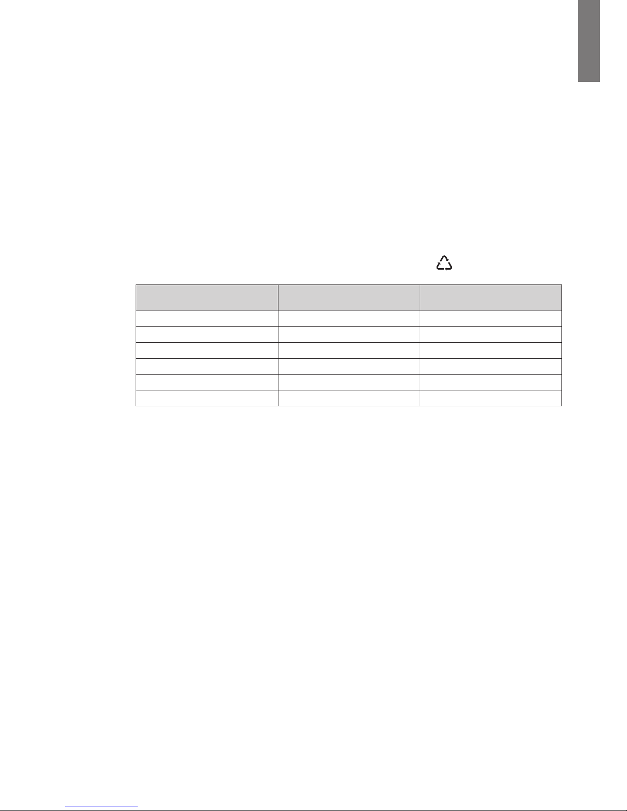
• Packing materials are recyclable and bear the appropriate identication symbol
01
PET
Materials Abbreviations
Number in
the identification symbols
Polyethylene terephthalat PET 01
High-density polyethylene HDPE 02
Polyvinyl chloride PVC 03
Low-density polyethylene LDPE 04
Polypropylene PP 05
Polystyrene PS 06
Follow all local regulations for the disposal of packing materials.
End of life
HP processes products at the end of their service lives in compliance with local regulations.
HP works with companies in charge of collecting and eliminating our products at the end of
their service lives.
Product
The product is made up of recyclable materials.
Dismantling and destruction must take place in compliance with all local regulations concerning waste.
At the end of its service life, the product must be transported to a processing center for electrical and
electronic waste.
Battery
The product contains lead-acid batteries that must be processed according to applicable local regulations
concerning batteries.
The battery may be removed to comply with regulations and correct disposal.
Page 6
Page 6
792523-001 Edition 1
ENGLISH
1. Overview
1.2 Weights and dimensions
D
H
W
Description Weights
(kg/lb)
Dimensions (mm/inch)
D x W x H
HP T750 G4 NA/JP UPS 10.9 kg/24 lb. 345 x 150 x 231 mm/13.6 x 5.9 x 9.1 in.
HP T1000 G4 NA/JP UPS 11.3 kg/25 lb. 345 x 150 x 231 mm/13.6 x 5.9 x 9.1 in.
HP T1500 G4 NA/JP UPS 16.3 kg/36 lb. 445 x 150 x 231 mm/17.5 x 5.9 x 9.1 in.
HP T750 G4 INTL UPS 10.4 kg/23 lb. 345 x 150 x 231 mm/13.6 x 5.9 x 9.1 in.
HP T1000 G4 INTL UPS 10.4 kg/23 lb. 345 x 150 x 231 mm/13.6 x 5.9 x 9.1 in.
HP T1500 G4 INTL UPS 15.2 kg/33.5 lb. 445 x 150 x 231 mm/17.5 x 5.9 x 9.1 in.
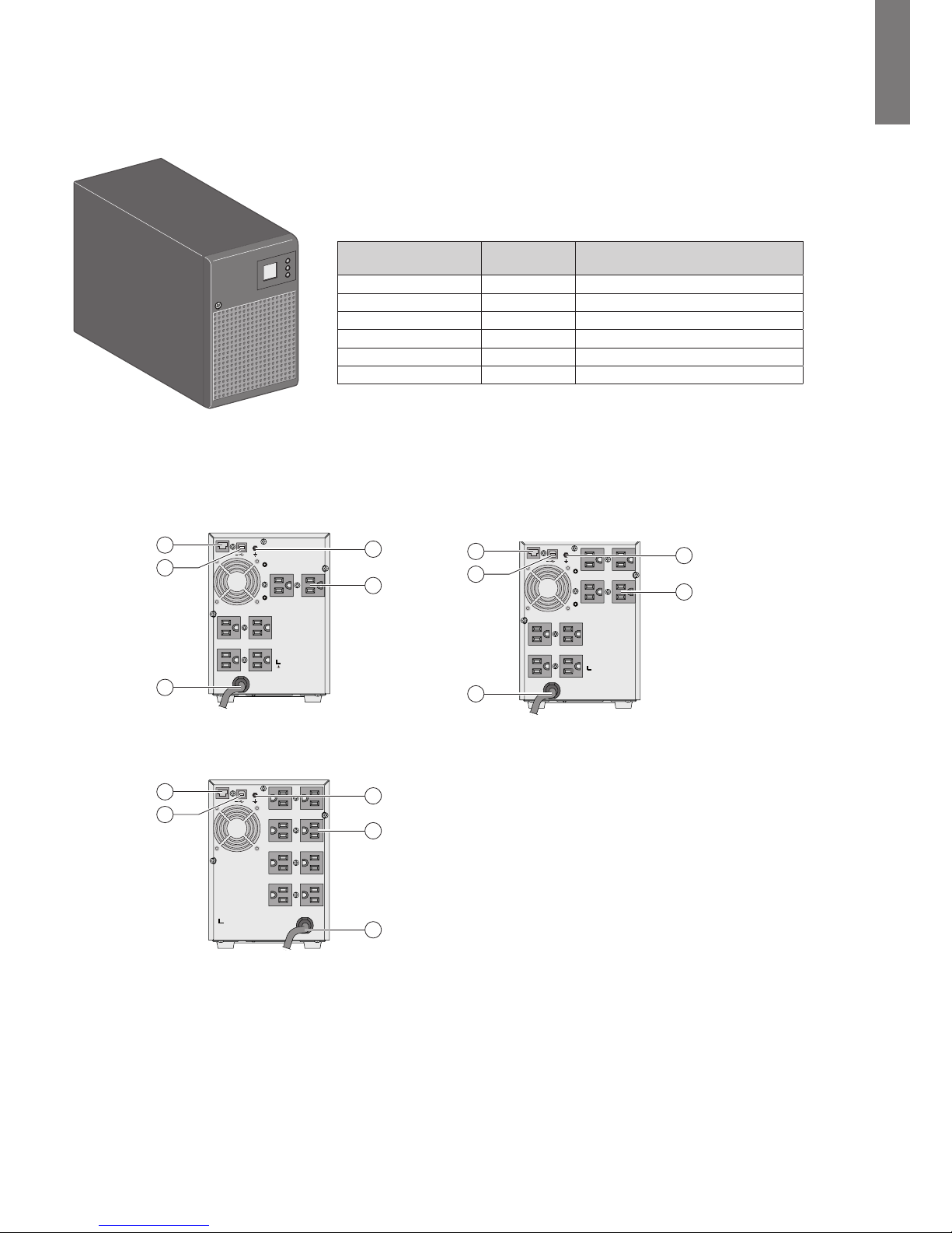
1.3 Rear panels
HP T750 G4 NA/JP UPS HP T1000 G4 NA/JP UPS
INPUT
OUTPUT
OUTPUT
RS232 OR
5
3
4
1
2
Refer to the Bottom of
the unit for caution markings!
HP T1500 G4 NA/JP UPS
INPUT
OUTPUT
RS232 OR
Refer to the Bottom of
the unit for caution markings!
5
3
4
1
2
(1) USB communication port
(2) RS-232 communication port
(3) Outlets for connection of critical equipment
(4) Attached 6-ft. input power cord for AC power source
(5) Ground screw
INPUT
OUTPUT
OUTPUT
RS232 OR
Refer to the Bottom of
the unit for caution markings!
5
3
4
1
2
Page 7

792523-001 Edition 1
Page 7
ENGLISH
1. Overview
HP T750 G4 INTL UPS HP T1000 G4 INTL UPS
INPUT
OUTPUT
Refer to the Bottom of
the unit for caution markings!
RS232 OR
5
4
3
2
1
INPUT
OUTPUT
OUTPUT
Refer to the Bottom of
the unit for caution markings!
RS232 OR
5
4
3
2
1
HP T1500 G4 INTL UPS
INPUT
OUTPUT
Refer to the Bottom of
the unit for caution markings!
RS232 OR
5
4
3
2
1
(1) USB communication port
(2) RS-232 communication port
(3) Outlets for connection of critical equipment
(4) Socket for connection to AC power source
(5) Ground screw
Page 8

Page 8
792523-001 Edition 1
ENGLISH
2. User Interface
2.1 Control panel
The UPS has a three-button control panel.
AVR
%
Min
Hz
kVA
kW
6
7
8
6
On/Off button
7
Scroll
8
Mute alarm
2.2 LCD window
The LCD window provides useful information about the UPS, load status, events, measurements, and settings.
16
15
14
17
11
10
9
12
13
9
UPS on line mode
10
AVR (Automatic Voltage Regulation )
mode
11
Battery mode
12
Internal fault
13
Output load level
14
Battery level
15
Input measurements
16
Output measurements
17
Measuring unit
Page 9

792523-001 Edition 1
Page 9
ENGLISH
2.3 UPS setting through the LCD
Tower UPS HP T750 G4 NA/JP UPS, HP T1000 G4 NA/JP UPS, HP T1500 G4 NA/JP UPS
Release the scroll down button to select a menu.
5s
2s
2s
Alarm
Output voltage Sensitivity
(1)
2s
Tower UPS HP T750 G4 INTL UPS, HP T1000 G4 INTL UPS, HP T1500 G4 INTL UPS
Release the scroll down button to select a menu.
5s 2s
2s
2s
Output voltageAlarm
Sensitivity
(1)
Note: In Lo (low sensitivity) mode, the UPS will tolerate more uctuations in power and goes on battery power less often.
If the connected load is sensitive to power disturbances, keep the sensitivity as Std (Standard).
Example of setting
Save the new value
10s 5s 5s
Note: The LCD shuts o if there is no activity for three minutes.
2. User Interface
Page 10

Page 10
792523-001 Edition 1
ENGLISH
3. Installation
3.1 Unpacking and contents check
(1) HP Tower UPS
(2) Documentation
(4) Two connection cables for protected equipment (HP T750 G4 INTL UPS, HP T1000 G4 INTL UPS, HP T1500 G4 INTL UPS)
(5) RS-232 communication cable
(6) USB communication cable
Packing materials must be disposed of in compliance with all local regulations concerning waste.
Recycling symbols are printed on the packing materials to facilitate sorting.
1
2
4
5
6
3.2 Battery module connection
This operation must be performed when the UPS is switched o and unplugged from the AC source. In addition, do not
disconnect the connector while the unit is operating from the AC source or in reserve mode.
Note: Before starting the UPS, connect the internal battery. A small amount of arcing may occur when connecting the
batteries. This is normal and does not damage the UPS or present any safety concern.
B
A
C
A
Remove bezel.
B
Connect the
battery module.
Never pull on the
wires.
C
Attach the bezel.
Page 11

792523-001 Edition 1
Page 11
ENGLISH
3. Installation
3.3 Communication ports
Connection of RS-232 or USB communication port
The RS-232 and USB communication ports cannot operate simultaneously.
2
1
5
6
A
Connect the RS-232 5 or USB
6
communication cable to
the serial or USB port on
the computer equipment.
Connect the other end of the
communication cable to the USB
1
or RS-232 2 communication
port on
the UPS.
The UPS can now communicate with
HP power management software.
3.4 Ground connection
B
Page 12

Page 12
792523-001 Edition 1
ENGLISH
4. Operation
4.1 Start-up and normal operation
To start the UPS:
1. Verify that the UPS power cord is plugged in.
2. Press the button on the UPS control panel for at least two seconds.
3. Check the UPS LCD window display for active alarms.
If the indicator is on, do not proceed until all alarms are cleared.
Correct the alarms and restart if necessary.
4. Verify that the indicator illuminates, indicating that the UPS is operating normally and any loads are powered and
protected.
4.2 Starting the UPS on battery
Before using this feature, the UPS must have been powered by utility power with output enabled
at least once.
To start the UPS on battery:
1. Press the button on the UPS control panel until the UPS LCD window display illuminates.
The UPS cycles through Standby mode to Battery mode. The indicator illuminates.
The UPS supplies power to your equipment.
2. Check the UPS LCD window display for active alarms. Resolve any active alarms before continuing.
See "5.1 Troubleshooting", page 13.
4.3 UPS shutdown
To shut down the UPS:
1. Press the button on the UPS control panel for three seconds.
2. The audio alarm beeps and shows a status of "UPS shutting OFF...". The UPS then transfers to Standby mode and the
indicator turns o.
3. The audio alarm stops.
4.4 Operation on battery power
Transfer to battery power
• The connected devices continue to be supplied by the UPS when AC input power is no longer available.
The necessary energy is provided by the battery.
• The indicator illuminates.
• The audio alarm beeps every 10 seconds.
The connected devices are supplied by the battery.
Low-battery warning
• The indicator illuminates solid.
• The audio alarm beeps every three seconds.
• The remaining battery power is low. Shut down all applications on the connected equipment because automatic UPS
shutdown is imminent.
End of battery backup time
• LCD displays "End of backup time."
• All the LEDs go o.
• The audio alarms stops.
4.5 Return of AC input power
Following an outage, the UPS restarts automatically when AC input power returns (unless the restart
function has been disabled) and the load is supplied again.
Page 13

792523-001 Edition 1
Page 13
ENGLISH
5. Maintenance
5.1 Troubleshooting
Operation status Possible cause Action
Overload
Power requirement exceeds the UPS
capacity (greater than 105% of nominal).
Remove some of the equipment from
the UPS. The UPS continues to operate,
but may shutdown if the load increases.
The alarm resets when the condition
becomes inactive.
Short-circuit fault A short-circuit occurred. Check device connection or
integrity.
If the error persists, note the alarm
message and the UPS serial number, and
then contact your service representative.
Battery fault The batteries in the UPS are
disconnected.
Verify that all batteries are properly
connected.
If the error persists, note the alarm
message and the UPS serial number, and
then contact your service representative.
The end of battery life is reached. Contact your service representative
for battery replacement.
Fan fault The UPS has a fan fault. Check that no object is blocking the
fan.
If the error persists, note the alarm
message and the UPS serial number, and
then contact your service representative.
Charger fault The UPS has a charger fault. The UPS does not charge the
battery anymore.
Note the alarm message and
the UPS serial number, and then
contact your service representative.
5.2 Updating the UPS rmware
To update the UPS rmware, see the HP website (http://www.hp.com/go/rackandpower).
5.3 Battery module replacement
Safety recommendations
Warning: To prevent personal injury from hazardous energy:
• This operation must be performed when the UPS is switched o and unplugged from the AC source.
• Do not disconnect the connector while the unit is operating from the AC mains or in reserve mode.
• The battery connection must not be disconnected while running in reserve mode.
• The battery can cause electrocution and high short-circuit currents. The following safety precautions
are required before servicing the battery components:
• Remove watches, rings, bracelets, and all other metal objects from the hands and arms.
• Use tools with an insulated handle.
• Do not place tools or metal parts on top of batteries.
Page 14

Page 14
792523-001 Edition 1
ENGLISH
Replacing the batteries
• Read and observe the requirements in "Important battery safety information" and "Battery care and
storage guidelines" in this section before battery module replacement.
• Follow the instructions in this section to replace the battery module.
Note: Replace all battery modules at the same time.
Important battery safety information
Warning: The unit contains sealed lead-acid battery modules. To prevent re or chemical burns:
• Do not attempt to recharge batteries after removal from the unit.
• Do not disassemble, crush, or puncture the batteries.
• Do not short the external contacts of the batteries.
• Do not immerse the batteries in water.
• Do not expose to temperatures higher than 60°C (140°F).
Battery care and storage guidelines
Caution: Because of the short shelf life of the batteries, avoid storing a battery spare as a
backup. Do not maintain an inventory of spare batteries on site unless a procedure to keep
these batteries charged while in storage is implemented.
To maintain the batteries:
• Minimize the amount of time the UPS uses battery power by matching the UPS conguration with the utility voltage
(see "6.1 HP T750 G4 NA/JP UPS, HP T1000 G4 NA/JP UPS, and HP T1500 G4 NA/JP UPS", page 16 and "6.2 HP T750
G4 INTL UPS, HP T1000 G4 INTL UPS, and HP T1500 G4 INTL UPS", page 17).
• Keep the area around the UPS clean and dust-free. If the environment is very dusty, clean the outside of the UPS
regularly with a vacuum cleaner.
Battery module removal
5. Maintenance
A
B
A
Remove the bezel.
B
Disconnect the battery
module by separating the
connectors.
Never pull on the wires.
Page 15

792523-001 Edition 1
Page 15
ENGLISH
5. Maintenance
Battery tray removal (cont.)
C
D
Installing the new battery module
Perform the removal instructions in reverse order.
● To ensure safety and high performance, only use batteries supplied by HP.
● Take care to firmly press together the two parts of the connector during remounting.
5.4 Spares
Ordering Spares
To order a spare, visit the HP website (http://www.hp.com/buy/parts).
To replace parts under warranty, contact an HP authorized service representative.
UPS spare parts list
Item Spare Part Number
SPS-UPS T750 G4 NA/JP 796774-001
SPS-UPS T750 G4 INTL 796775-001
SPS-UPS T1000 G4 NA/JP
796763-001
SPS-UPS T1000 G4 INTL 796771-001
SPS-UPS T1500 G4 NA/JP 796772-001
SPS-UPS T1500 G4 INTL
796773-001
SPS-BATTERY KIT UPS T750 765781-001
SPS-BATTERY KIT UPS T1000 796779-001
SPS-BATTERY KIT UPS T1500 796780-001
C
Remove the plastic
protection cover
in front of the battery.
D
Pull the plastic tab to
remove the battery block
and replace the block.
Page 16

Page 16
792523-001 Edition 1
ENGLISH
6. Technical Specifications
6.1 HP T750 G4 NA/JP UPS, HP T1000 G4 NA/JP UPS, and HP T1500 G4 NA/JP UPS
HP T750 G4 NA/JP
UPS
HP T1000 G4 NA/JP
UPS
HP T1500 G4 NA/
JP UPS
Output Power @ 120V NA: 750 VA
525W
NA: 1000 VA
700W
NA: 1440 VA
1080W
Output Power @ 110V NA: 750 VA
525W
NA: 1000 VA
700W
NA: 1440 VA
1080W
Output Power @ 100V JPN: 750 VA
500W
JPN: 1000VA
680W
JPN: 1200 VA
980W
AC Input power
• Rated input voltage Single phase 100-120V
• Input voltage range 96 to 144V
• Input frequency
range
45 to 55 Hz (50 Hz system), 55 to 65 Hz (60 Hz system)
Output on battery power
• Voltage 100/110/120V (-10% to +5%)
(1)
• Frequency 50/60 Hz ±0.1 Hz
Battery (sealed lead acid, maintenance free)
• Standard
2 x 12V
7 Ah
2 x 12V
9 Ah
3 x 12V
9 Ah
Environment
• Operating tempera-
ture range
0 to 35°C/32 to 95°F
• Storage temperature
range
-15 to +40°C/5 to 104°F
• Relative humidity
0 to 90% (without condensation)
• Noise level
< 40 dBA in normal mode
(1) Adjustable to 100/110/120V, but must be set to the identical AC power source value.
Caution: To reduce the risk of re, connect only to a circuit provided with 20A maximum branch circuit overcurrent protection in accordance with the National Electric Code, ANSI/NFPA 70.
Filter
Transformer
AVR
Charger Inverter
Battery
Page 17

792523-001 Edition 1
Page 17
ENGLISH
6. Technical Specifications
6.2 HP T750 G4 INTL UPS, HP T1000 G4 INTL UPS, and HP T1500 G4 INTL UPS
HP T750 G4 INTL UPS HP T1000 G4 INTL UPS HP T1500 G4 INTL UPS
Output Power @ 230V 750 VA
525W
1000 VA
700W
1500 VA
1100W
AC Input power
• Rated input voltage
Single phase 220-240V
• Input voltage range
184 to 276V
• Input frequency range 45 to 55 Hz (50 Hz system), 55 to 65 Hz (60 Hz system)
Output on battery power
• Voltage
220/230/240V (-10% to +5%)
(1)
• Frequency 50/60 Hz ±0.1 Hz
Battery (sealed lead acid, maintenance free)
• Standard
1 x 12V
9 Ah
2 x 12V
7 Ah
3 x 12V
9 Ah
Environment
• Operating temperature
range
0 to 35°C/32 to 95°F
• Storage temperature
range
-15 to +40°C /5 to 104°F
• Relative humidity
0 to 90% (without condensation)
• Noise level < 40 dBA in normal mode
(1) Adjustable to 220/230/240V, but must be set to the identical AC power source value.
When the UPS is used in the EU area, use an external circuit breaker in front of the line with rating 16A,
250V which is IEC/EN 60898-1 standard compliant.
When the UPS is used in th NA area, use an external circuit breaker in front of the line with rating 20A, 250V.
Filter
Transformer
AVR
Charger Inverter
Battery
Page 18

Page 18
792523-001 Edition 1
ENGLISH
7. Support and other resources
Safety and regulatory compliance
For safety, environmental, and regulatory information, see Safety and Compliance Information for Server,
Storage, Power, Networking, and Rack Products, available at the HP website
(http://www.hp.com/support/Safety-Compliance-EnterpriseProducts).
Warranty information
HP ProLiant and X86 Servers and Options (http://www.hp.com/support/ProLiantServers-Warranties)
Before you contact HP
Be sure to have the following information available before you call HP:
• Active Health System log (HP ProLiant Gen8 or later products)
• Download and have available an Active Health System log for 7 days before the failure was detected. For more
information, see the HP iLO 4 User Guide or HP Intelligent Provisioning User Guide on the HP website (http://www.
hp.com/go/ilo/docs).
• Onboard Administrator SHOW ALL report (for HP BladeSystem products only)
• For more information on obtaining the Onboard Administrator SHOW ALL report, see the HP website (http://www.
hp.com/go/OAlog).
• Technical support registration number (if applicable)
• Product serial number
• Product model name and number
• Product identication number
• Applicable error messages
• Add-on boards or hardware
• Third-party hardware or software
• Operating system type and revision level
HP contact information
For United States and worldwide contact information, see the Contact HP website (http://www.hp.com/go/assistance).
In the United States:
• To contact HP by phone, call 1-800-334-5144. For continuous quality improvement, calls may be recorded or monitored.
• If you have purchased a Care Pack (service upgrade), see the Support & Drivers website (http://www8.hp.com/us/
en/support-drivers.html). If the problem cannot be resolved at the website, call 1-800-633-3600. For more information about Care Packs, see the HP website (http://pro-aq-sama.houston.hp.com/services/cache/10950-0-0-225-121.
html).
Product QuickSpecs
For more information about product features, specications, options, congurations, and compatibility, see the product
QuickSpecs on the HP website (http://www.hp.com/go/qs).
Documentation feedback
HP is committed to providing documentation that meets your needs. To help us improve the documentation, send any
errors, suggestions, or comments to Documentation Feedback (mailto: docsfeedback@hp.com). Include the document
title and part number, version number, or the URL when submitting your feedback.
 Loading...