

Page 1

Using HP-UX VLANs
HP 9000 Networking for HP-UX 11i
Manufacturing Part Number: T1453-90001
E0302
U. S. A.
© Copyright 2002 Hewlett-Packard Company.
Page 2

Legal Notices
The information in this document is subject to change without notice.
Hewlett-Packard makes no warranty of any kind with regard to this
manual, including, but not limited to, the implied warranties of
merchantability and fitness for a particular purpose. Hewlett-Packard
shall not be held liable for errors contained herein or direct, indirect,
special, incidental or consequential damages in connection with the
furnishing, performance, or use of this material.
Warranty. A copy of the specific warranty terms applicable to your
Hewlett- Packard product and replacement parts can be obtained from
your local Sales and Service Office.
Restricted Rights Legend. Use, duplication or disclosure by the U.S.
Government is subject to restrictions as set forth in subparagraph (c) (1)
(ii) of the Rights in Technical Data and Computer Software clause at
DFARS 252.227-7013 for DOD agencies, and subparagraphs (c) (1) and
(c) (2) of the Commercial Computer Software Restricted Rights clause at
FAR 52.227-19 for other agencies.
HEWLETT-PACKARD COMPANY
3000 Hanover Street
Palo Alto, California 94304
U.S.A.
Use of this manual and flexible disk(s) or tape cartridge(s) supplied for
this pack is restricted to this product only. Additional copies of the
programs may be made for security and back-up purposes only. Resale of
the programs in their present form or with alterations, is expressly
prohibited.
Copyright Notices. ©copyright 2002 Hewlett-Packard Company, all
rights reserved. ProCurve is a registered trademark of Hewlett-Packard
Company. DecNet is a trademark of Compaq Corporation. AppleTalk is a
trademark of Apple Computer Inc. Extreme and Summit are trademarks
of Extreme Networks Inc. Cisco and Catalyst are trademarks of Cisco
Systems Inc.
Reproduction, adaptation, or translation of this document without prior
written permission is prohibited, except as allowed under the copyright
laws.
2
Page 3

1. What are HP-UX VLANs?
HP-UX VLAN Features. . . . . . . . . . . . . . . . . . . . . . . . . . . . . . . . . . . . . . . . . . . . . . . . . . 12
Benefits of HP-UX VLANs. . . . . . . . . . . . . . . . . . . . . . . . . . . . . . . . . . . . . . . . . . . . . . . . 13
Types of VLANs Supported by HP-UX . . . . . . . . . . . . . . . . . . . . . . . . . . . . . . . . . . . . . . 14
HP-UX VLAN Tagging. . . . . . . . . . . . . . . . . . . . . . . . . . . . . . . . . . . . . . . . . . . . . . . . . . . 15
System and Software Requirements. . . . . . . . . . . . . . . . . . . . . . . . . . . . . . . . . . . . . . . . 17
Patches Required for the March 2002 HP-UX 11i-based Version . . . . . . . . . . . . . . . 17
Supported Switches . . . . . . . . . . . . . . . . . . . . . . . . . . . . . . . . . . . . . . . . . . . . . . . . . . . . . 19
Unsupported Functionality . . . . . . . . . . . . . . . . . . . . . . . . . . . . . . . . . . . . . . . . . . . . . . . 20
2. Overview of Installation and Configuration
Planning HP-UX VLANs. . . . . . . . . . . . . . . . . . . . . . . . . . . . . . . . . . . . . . . . . . . . . . . . . 22
How to Configure VLANs on the Switch. . . . . . . . . . . . . . . . . . . . . . . . . . . . . . . . . . . . . 23
How to Configure VLANs on HP-UX . . . . . . . . . . . . . . . . . . . . . . . . . . . . . . . . . . . . . . . 25
Choose Configuration Method: Use SAM; Edit vlanconf; Use lanadmin. . . . . . . . . . 25
Configuration Process . . . . . . . . . . . . . . . . . . . . . . . . . . . . . . . . . . . . . . . . . . . . . . . . . . . 26
Properties of a VLAN. . . . . . . . . . . . . . . . . . . . . . . . . . . . . . . . . . . . . . . . . . . . . . . . . . . . 27
Special Case of VLAN ID 0--Priority Tagged Frames . . . . . . . . . . . . . . . . . . . . . . . . . . 28
Promiscuous Mode Characteristics. . . . . . . . . . . . . . . . . . . . . . . . . . . . . . . . . . . . . . . . . 28
Allowable Values for HP VLANs . . . . . . . . . . . . . . . . . . . . . . . . . . . . . . . . . . . . . . . . . . . 29
Using VLANs with MC/ServiceGuard . . . . . . . . . . . . . . . . . . . . . . . . . . . . . . . . . . . . . . 31
How is 802.1p Priority Set?. . . . . . . . . . . . . . . . . . . . . . . . . . . . . . . . . . . . . . . . . . . . . . . 32
How do Pri and ToS Override Affect My Inbound and Outbound frames?. . . . . . . . . . 33
Setting 802.1p Priority, ToS, and Overrides. . . . . . . . . . . . . . . . . . . . . . . . . . . . . . . . . . 35
Where to Get More Information . . . . . . . . . . . . . . . . . . . . . . . . . . . . . . . . . . . . . . . . . . . 35
Contents
3. Configuring VLANs Using SAM
Configuring VLANs Using SAM . . . . . . . . . . . . . . . . . . . . . . . . . . . . . . . . . . . . . . . . . . . 38
4. Configuring VLANs by Editing vlanconf File
Modifying Parameters in vlanconf File. . . . . . . . . . . . . . . . . . . . . . . . . . . . . . . . . . . . . . 44
5. Using lanadmin -V to Administer VLANs
Using the lanadmin -V Command for Administering VLANs. . . . . . . . . . . . . . . . . . . . 48
lanadmin Syntax. . . . . . . . . . . . . . . . . . . . . . . . . . . . . . . . . . . . . . . . . . . . . . . . . . . . . . 48
Using lanadmin to Create a VLAN . . . . . . . . . . . . . . . . . . . . . . . . . . . . . . . . . . . . . . . 49
Using a VLAN. . . . . . . . . . . . . . . . . . . . . . . . . . . . . . . . . . . . . . . . . . . . . . . . . . . . . . . . 51
Using lanadmin to Modify a VLAN . . . . . . . . . . . . . . . . . . . . . . . . . . . . . . . . . . . . . . . 51
3
Page 4

Contents
Using lanadmin to Delete a VLAN . . . . . . . . . . . . . . . . . . . . . . . . . . . . . . . . . . . . . . . 52
A. Troubleshooting
Diagnostic Flowcharts . . . . . . . . . . . . . . . . . . . . . . . . . . . . . . . . . . . . . . . . . . . . . . . . . . . 57
Flowchart 1: Link Level Tests. . . . . . . . . . . . . . . . . . . . . . . . . . . . . . . . . . . . . . . . . . . . . 58
Flowchart 1a: Linkloop Test. . . . . . . . . . . . . . . . . . . . . . . . . . . . . . . . . . . . . . . . . . . . . 60
Flowchart 2: Network Level Tests. . . . . . . . . . . . . . . . . . . . . . . . . . . . . . . . . . . . . . . . . . 64
Flowchart 2 Procedures . . . . . . . . . . . . . . . . . . . . . . . . . . . . . . . . . . . . . . . . . . . . . . . . 65
NetTL Trace and Log of VLANs . . . . . . . . . . . . . . . . . . . . . . . . . . . . . . . . . . . . . . . . . . . 72
Glossary . . . . . . . . . . . . . . . . . . . . . . . . . . . . . . . . . . . . . . . . . . . . . . . . . . . . . . . . 75
4
Page 5

Tables
Table 1-1. Needed Patches for HP-UX VLANs . . . . . . . . . . . . . . . . . . . . . . . . . . . . . . 17
Table 2-1. Summary of VLAN Tagging Assignment . . . . . . . . . . . . . . . . . . . . . . . . . 24
Table 2-2. Allowable Values for Parameters in vlanconf File . . . . . . . . . . . . . . . . . . 29
Table 2-3. ToS to 802.1 User Priority Mappings Based on IP Precedence . . . . . . . . 32
Table 2-4. Allowable Settings for VLAN_PRI_OVERRIDE Value in vlanconf File . 33
Table 2-5. Allowable Settings for VLAN_TOS_OVERRIDE Value in vlanconf File. 34
Table A-1. Flowchart Descriptions . . . . . . . . . . . . . . . . . . . . . . . . . . . . . . . . . . . . . . . 57
5
Page 6

Tables
6
Page 7

Figures
Figure 1-1. VLANs (Virtual LANs) . . . . . . . . . . . . . . . . . . . . . . . . . . . . . . . . . . . . . . . 10
Figure 1-2. IEEE 802.1Q VLAN Tag in Ethernet Frame. . . . . . . . . . . . . . . . . . . . . . 15
Figure 1-3. VLANS Overlapping or Sharing the Same LAN Card Port . . . . . . . . . . 16
Figure 2-1. Communication between VLANS Requires an External Router . . . . . . 22
Figure 2-2. Tagged and Untagged VLAN Technology in Same Network . . . . . . . . . 23
Figure 2-3. VLANs and Service Guard . . . . . . . . . . . . . . . . . . . . . . . . . . . . . . . . . . . . 31
Figure 3-1. List Pulldown with Virtual LANs Displayed. . . . . . . . . . . . . . . . . . . . . . 38
Figure 3-2. Action Pulldown for Creating Virtual LANs. . . . . . . . . . . . . . . . . . . . . . 39
Figure 3-3. Create Virtual LANs. . . . . . . . . . . . . . . . . . . . . . . . . . . . . . . . . . . . . . . . . 40
Figure 3-4. Add an IP Address for the VLAN. . . . . . . . . . . . . . . . . . . . . . . . . . . . . . . 41
Figure A-1. Flowchart 1. . . . . . . . . . . . . . . . . . . . . . . . . . . . . . . . . . . . . . . . . . . . . . . . 59
Figure A-2. Flowchart 1a. . . . . . . . . . . . . . . . . . . . . . . . . . . . . . . . . . . . . . . . . . . . . . . 60
Figure A-3. Flowchart 1b. . . . . . . . . . . . . . . . . . . . . . . . . . . . . . . . . . . . . . . . . . . . . . . 62
Figure A-4. Flowchart 2. . . . . . . . . . . . . . . . . . . . . . . . . . . . . . . . . . . . . . . . . . . . . . . . 64
Figure A-5. Flowchart 2a. . . . . . . . . . . . . . . . . . . . . . . . . . . . . . . . . . . . . . . . . . . . . . . 66
Figure A-6. Flowchart 2b. . . . . . . . . . . . . . . . . . . . . . . . . . . . . . . . . . . . . . . . . . . . . . . 68
Figure A-7. Flowchart 2b (continued) . . . . . . . . . . . . . . . . . . . . . . . . . . . . . . . . . . . . . 70
7
Page 8

Figures
8
Page 9

1 What are HP-UX VLANs?
Chapter 1 9
Page 10
What are HP-UX VLANs?
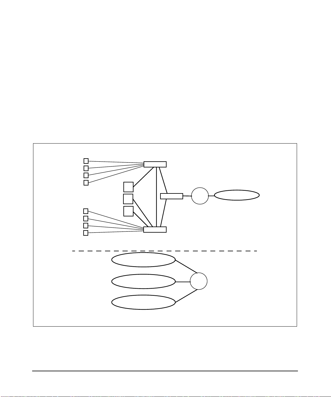
A Virtual LAN (VLAN) is a logical or virtual network segment that can
span multiple physical network segments. Using VLANs, you can group
switched-network end-stations by:
• department, such as engineering and manufacturing,
• type of user, such as power users or those with special needs,
• application, or
• project
instead of physical location (Figure 1-1).
Figure 1-1 VLANs (Virtual LANs)
End
Users
Switches
Servers
Internetwork
Router
LAN 2
Physical View
Marketing VLAN
Engineering VLAN
Manufacturing VLAN
Internetwork
Router
Logical View
VLANs isolate broadcast and multicast traffic by determining which
destinations should receive that traffic, thereby making better use of
switch and end-station resources. With VLANs, broadcasts and
multicasts go only to the intended nodes in the virtual LAN.
Chapter 110
Page 11

What are HP-UX VLANs?
VLANs create broadcast domains using switches instead of routers.
While VLANs in some environments may reduce the number of routers
needed (and their latency), you still need a router if you want the VLANs
to communicate with each other.
Chapter 1 11
Page 12

What are HP-UX VLANs?
HP-UX VLAN Features
HP-UX VLAN Features
Following are some of the features of HP-UX VLANs:
• HP-UX VLANs are implemented with host-based IEEE 802.1Q/p
• HP VLANs are for use over fast Ethernet or gigabit Ethernet LAN
• HP-UX VLANs do not require you to rewrite applications, install
compliant tagging to allow configuring multiple VLANs on a given
Ethernet LAN card based on their IP-subnet, protocol, or LAN card
port.
cards running on HP-UX 11i (11.11) PA-RISC-based servers and
workstations. HP-UX supports up to 1024 VLANS per LAN card
port.
new hardware, or recable. They are also compatible with HP
MC/ServiceGuard as well as HP’s online addition and replacement
(OLAR) capabilities.
Chapter 112
Page 13

What are HP-UX VLANs?
Benefits of HP-UX VLANs
Benefits of HP-UX VLANs
The advantages of HP-UX VLANs are:
• Physically dispersed workgroups can be logically connected within
the same broadcast domain to appear as if they are on the same
physical LAN.
• A single physical link can simultaneously serve several IP subnets
when subnet-based VLANs are configured on that link.
• Switches no longer need to classify and tag traffic. They focus on
forwarding packets.
• Workgroups requiring increased security can be logically connected
within the same broadcast domain. Broadcast traffic will be isolated
within the secure group.
• End stations using VLANs can offer rudimentary class of service
(CoS) locally by prioritizing traffic for certain activities.
• HP-UX VLANs can be created, modified, and deleted without
rebooting.
• HP-UX VLANs are interoperable with non-VLAN aware devices,
that is, devices such as servers or bridges that do not transmit or
receive tagged packets.
Chapter 1 13
Page 14

What are HP-UX VLANs?
Types of VLANs Supported by HP-UX
Types of VLANs Supported by HP-UX
The types of HP-UX VLANs that you can create are as follows:
• NIC-Port Based--A group of physical LAN card ports belong to the
same layer-2 broadcast domain. Each LAN card port transmits and
receives frames belonging to the VLAN associated with that port.
Members of the same port-based VLAN all have the same VLAN ID.
A VLAN ID uniquely identifies the VLAN to which a frame belongs.
• Protocol Based--Common protocols such as IP, IPX, AppleTalk,
Decnet, and NetBIOS are grouped into layer-2 broadcast domains.
• IP Subnet Based--Each IP subnet has its own unique VLAN. Traffic
from different subnets is logically separated from each other as if
each subnet were on a different LAN segment.
Please refer to “Planning HP-UX VLANs” in this document for more
information on setting up the different types of VLANs described.
HP-UX VLANs conform to IEEE specifications 802.1Q (for VLAN
tagging) and IEEE 802.1p (MAC-level frame prioritizing) to provide
end-to-end class of service (CoS).
Chapter 114
Page 15
HP-UX VLAN Tagging
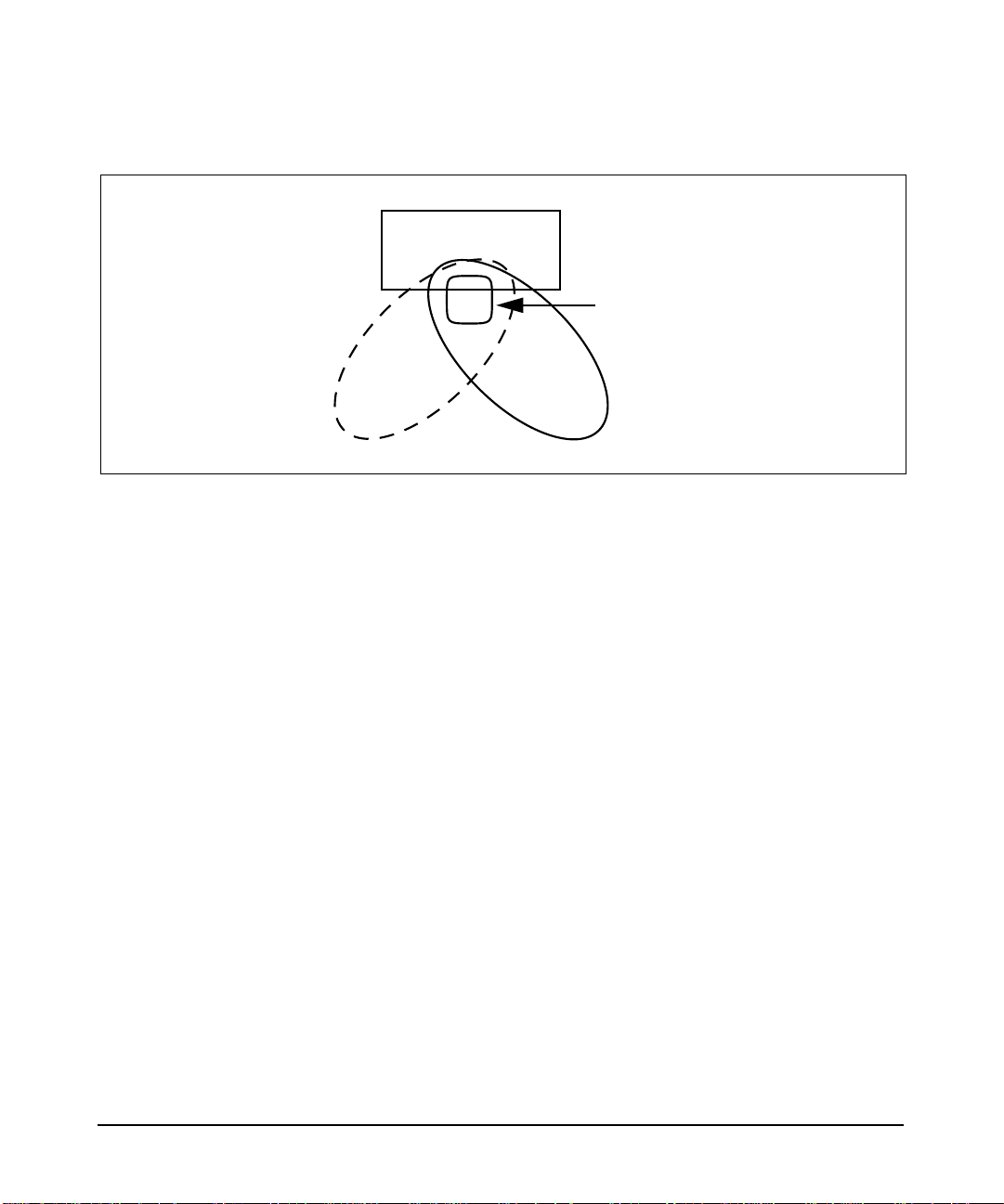
Network switches and end stations that know about VLANs are said to
be VLAN-aware. Network switches and end stations that can interpret
VLAN tags are said to be VLAN-tag-aware. HP-UX VLAN-tag-aware
end stations add VLAN tags to standard Ethernet frames--a process
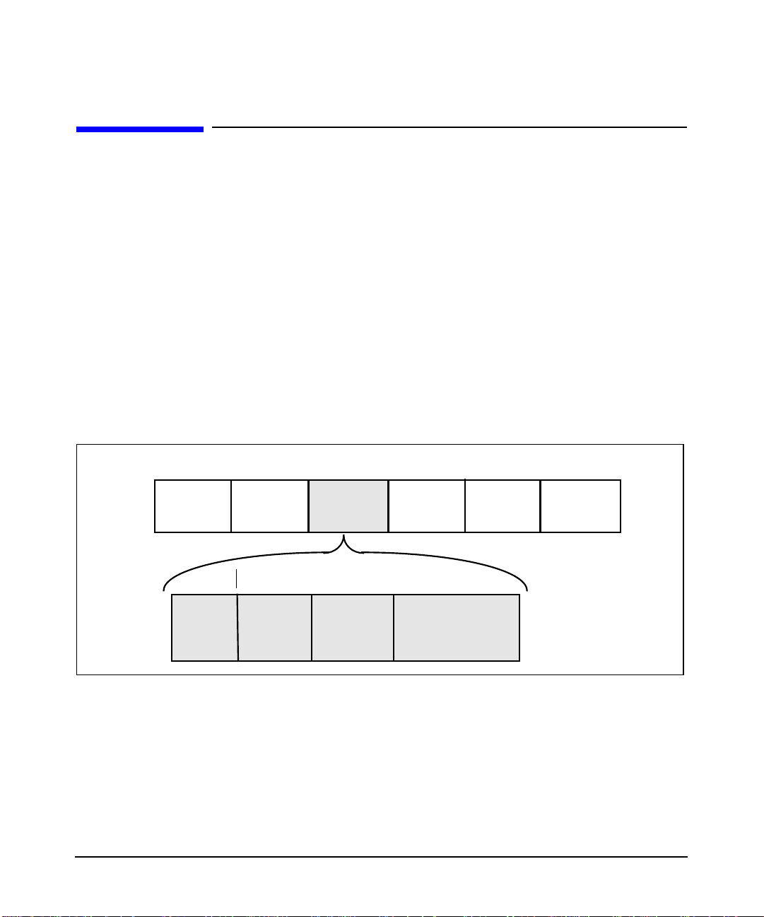
called explicit tagging. A VLAN tag (Figure 1-2) identifies which
VLAN a data frame belongs to and enables traffic from more than one
VLAN to use the same switch or LAN card port (Figure 1-3).
When a VLAN-aware switch receives data from an end-station, the
switch determines where the data is to go and whether the VLAN ID
should be retained. If the data is to go to a device that can recognize the
VLAN tag, the VLAN tag is retained. If the data is to go to a device that
has no knowledge of VLANs (VLAN-unaware), the switch sends the
data without the VLAN tag.
Figure 1-2 IEEE 802.1Q VLAN Tag in Ethernet Frame
4 Bytes
What are HP-UX VLANs?
HP-UX VLAN Tagging
Destination
Address
2 Bytes
Tag
Protocol
ID
Source
Address
2 Bytes (Tag Control Information)
User
Priority
3 bits
802.1Q
VLAN Tag
Canonical
Format
Indicator
1 bit
Type/Len Data Frame
Check
VLAN ID
12 bits
You must configure VLAN tagging on switch ports that interface to
end-stations that have tagged VLANs. If a switch or end-station port is
member of only a single, port-based VLAN, tagging is not required.
To transmit tagged frames, you must configure a VLAN on the
end-station with a VLAN ID that matches the VLAN ID of a tagged
VLAN on the switch port and the VLAN ID of a VLAN at the remote
end-station. Refer to the next 3 chapters in this guide for complete
details on configuring VLANs on your HP-UX end stations.
Chapter 1 15
Page 16
What are HP-UX VLANs?
HP-UX VLAN Tagging
Figure 1-3 VLANS Overlapping or Sharing the Same LAN Card Port
Server
HP Gigabit or Fast Ethernet
LAN Card
Port
VLAN0 VLAN1024
Chapter 116
Page 17

What are HP-UX VLANs?
System and Software Requirements
System and Software Requirements
Following are the hardware and software requirements for VLANs as of
March 2002:
• Type of HP System Required
— HP-UX Precision Architecture (PA-RISC).
• OS Required
— HP-UX 11i (11.11). New HP servers and workstations shipped
after March 2002 already have VLAN technology pre-installed in
the operating environment. For computers shipped before March
2002, check the product Information Sheet to see if the VLAN
product can be loaded by way of required patches.
• VLANs work over all HP HSC and PCI 100Base LAN cards and all
HP HSC and PCI 1000Base LAN cards.
PatchesRequired for the March 2002 HP-UX 11i-based Version
The following patches are required in order to use the HP-UX VLAN
software on HP-UX 11i-based systems.
These patch numbers are current at the time of publication and may be
superseded. Check to see if these patches are superseded, and download
patches at the following URL: http://us-support.external.hp.com/
Table 1-1 Needed Patches for HP-UX VLANs
Driver 11i Patch #
Transport PHNE_25644
100Base-T * PHNE_23465
Gigabit * PHNE_24491
nettl, netfmt, and nettladm PHNE_24473
LAN--core patch that enables
VLANs
Chapter 1 17
PHNE_25388
Page 18

What are HP-UX VLANs?
System and Software Requirements
Table 1-1 Needed Patches (Continued)for HP-UX VLANs (Continued)
Driver 11i Patch #
SAM PHCO_25866
* Either the 100Base-T or Gigabit patch
may be optional depending on which
link type you have.
Chapter 118
Page 19

What are HP-UX VLANs?
Supported Switches
Supported Switches
HP-UX VLANs are supported with switches that implement IEEE
802.1Q-compliant VLAN tagging. The switches must implement at least
port-based VLANs and must be VLAN-tag aware. The following switches
are among those that support HP-UX VLANs:
• HP ProCurve 9304M
• HP ProCurve 4000M/8000M
• Extreme Summit 7i
• Cisco Catalyst 6509
Chapter 1 19
Page 20

What are HP-UX VLANs?
Unsupported Functionality
Unsupported Functionality
HP-UX VLANs do not support the following functionality:
• GARP VLAN registration protocol (GVRP) is currently not
• HP-UX VLANs do not operate on:
supported. HP-UX VLANs will not send GVRP messages or interpret
them.
— Any Itanium-based servers whether the LAN card is factory
installed or customer installed.
— HP-UX 11.20, 11.0, and 10.20.
— FDDI, Token Ring, ATM, 100VG, EISA, and HP-PB LAN cards.
Chapter 120
Page 21

2 Overview of Installation and
Configuration
Chapter 2 21
Page 22
Overview of Installation and Configuration
Planning HP-UX VLANs
Planning HP-UX VLANs
The following requirements must be satisfied before setting up VLANs in
an HP-UX network:
• In order for both end stations of a VLAN to communicate, both the
end-station LAN cards and the switch ports that are connected to
those LAN cards on a point-to-point link need to be VLAN-tag-aware.
• For VLANs to communicate with each other, an external
VLAN-aware switch or router is required (Figure 2-1). However,it is
not possible to extend a single vlan across a router.
• If a hub is connected to a network of VLANs, every port on the hub
must belong to the same VLAN. Hubs do not have the ability to
provide VLANs to individual ports.
VLAN awareness does not provide any benefit in a shared LAN
environment (using hubs or repeaters). In these shared LAN
environments, all stations see all traffic whether it is VLAN tagged or
not.
Figure 2-1 Communication between VLANS Requires an External Router
LAN Card with Two
Port-Based
VLANs Configured
Port A2
Port A4
Chapter 222
External
Router
Red VLAN
Port A1
Port A3
Green VLAN
Page 23
Overview of Installation and Configuration
How to Configure VLANs on the Switch
How to Configure VLANs on the Switch
IEEE 802.1Q compliant devices and legacy/untagged VLANs can coexist
on the same networks, but legacy/untagged VLANS require a separate
link, whereas the 802.1Q tagged VLANs can combine several VLANs
into one link. On 802.1Q-compliant devices, separate ports (configured as
untagged) must be used to connect separate VLANs to non-802.1Q
devices.
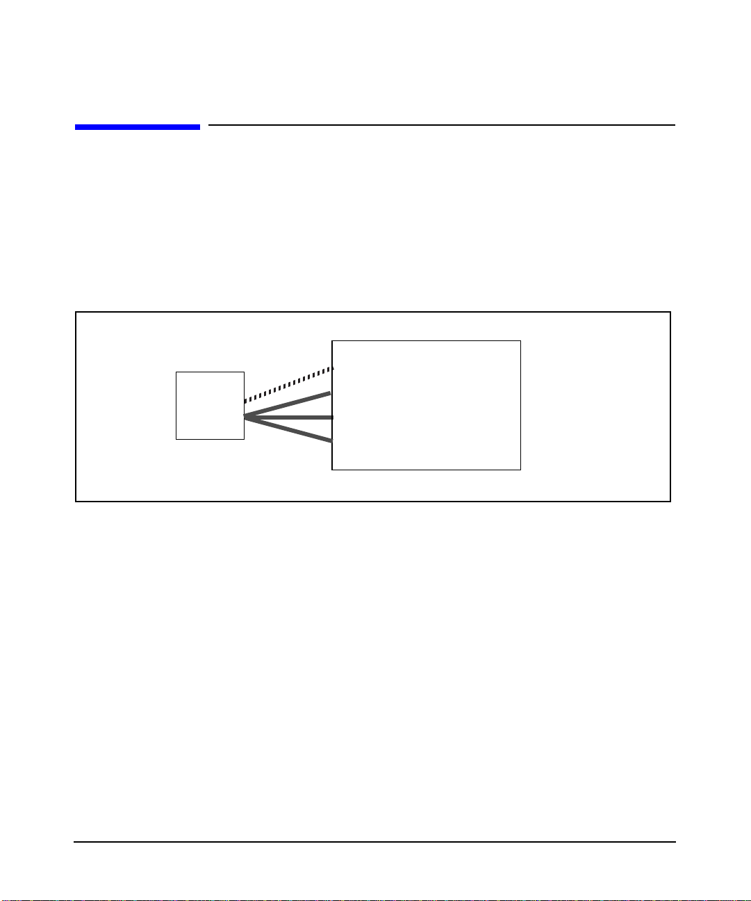
Figure 2-2 Tagged and Untagged VLAN Technology in Same Network
Switch Port
untagged or native VLAN
tagged VLAN
tagged VLAN
tagged VLAN
LAN
Card
Port
Untagged
Tagged
VLAN 1
VLAN 2
VLAN 3
VLAN 4
When you assign a switch port to a given VLAN,you must implement the
VLAN tag if the switch port will carry traffic for more than one VLAN.
Otherwise, the port VLAN assignment can remain untagged because
the tag is not needed. On a given switch, use the untagged designation
for a port VLAN assignment where the port is connected to a
non-802.1Q-compliant device or is assigned to only one VLAN as in
VLAN 1 in Figure 2-2. Use the tagged designation when more than one
VLAN is assigned to the port, or the port is connected to a device that
does comply with the 802.1Q standard as in VLANs 2 through 4 in
Figure 2-2. These simple rules are summarized in Table 2-1.
Chapter 2 23
Page 24

Overview of Installation and Configuration
How to Configure VLANs on the Switch
Table 2-1 Summary of VLAN Tagging Assignment
VLANs Per
Port
1 Untagged or Tagged. If the device connected
2 or more 1 VLAN Untagged; all others Tagged
A given VLAN must have the same VLAN ID on any
802.1Q-compliant device in which the VLAN is configured.
Tagging Scheme
to the port is 802.1Q-compliant, then the
recommended choice is “Tagged.”
or
All VLANs Tagged
Chapter 224
Page 25

Overview of Installation and Configuration
How to Configure VLANs on HP-UX
How to Configure VLANs on HP-UX
Choose Configuration Method: Use SAM; Edit
vlanconf; Use lanadmin
There are three ways to configure VLANs: the first two methods preserve
configuration changes across reboots; the third applies changes
immediately but doesn’t preserve configuration changes across reboots:
To permanently save your configurations, you can either:
• Use the GUI-based system admin manager (SAM). To use SAM,
refer to the instructions in “Configuring VLANs Using SAM” in this
document for details, and then do the steps for verifying VLANs.
Using SAM reduces risk of errors and saves your data permanently.
If you use, SAM, configuration doesn’t require a reboot to take effect.
or
• Edit the /etc/rc.config.d/vlanconf configuration file using an editor
such as “vi.” Changes will not take effect until the next reboot. Refer
to “Configuring VLANs by Editing the vlanconf File” in this
document for instructions on editing the configuration file for
VLANs.
To temporarily configure VLANs on a live system, you can:
• Use the lanadmin command from the HP-UX command line.
CAUTION If you use the lanadmin command to administer VLANs, those changes
are not preserved across reboots. See “Using the lanadmin Command for
Administering VLANs” for details on the lanadmin command.
Chapter 2 25
Page 26

Overview of Installation and Configuration
Configuration Process
Configuration Process
Following are the steps to configure HP-UX VLANs. These steps are for
defining VLAN membership, assigning names, VLAN IDs, and port
assignments. This procedure assumes that the switches can add VLAN
tags:
1. Determine the network topology affected. Either draw the affected
network topology or list it. Include all affected end
stations--workstations and servers.
2. Define the VLANs. Decide, according to your requirements, which
systems belong to which logical groups.
3. Assign VLAN IDs to each VLAN. Ensure that the assignments are
consistent across endstations and switches; otherwise, stations will
not communicate with each other. A VLAN ID can be any number
between 0 and 4094 that is used only once within that port.
NOTE The VLAN ID is not the same as the number of VLANs supported
--HP-UX supports up to 1024 VLANS per LAN card port.
4. Determine which LAN card ports need tagged VLANs and which do
not. Typically, you may need to put a server LAN card port in several
VLANs while a desktop LAN card port can belong to just one VLAN.
5. Assign VLAN IDs to each LAN card port on end stations and
switches. Mark VLANs on the switches as tagged or untagged
according to the LAN card port to which they are connected.
6. On HP-UX servers that must belong to several VLANs, create
VLANs on the corresponding LAN card ports.
Chapter 226
Page 27

Overview of Installation and Configuration
Properties of a VLAN
Properties of a VLAN
When a VLAN is created on a given LAN card port, (see “Creating a
VLAN”), the system generates a virtual PPA or VPPA which can be used
to send and receive 802.1Q tagged frames on that LAN card. Each
HP-UX VLAN has a Virtual PPA associated with it. A VPPA has
essentially the same properties as a physical point of attachment (PPA)
on a LAN card. The differences are:
1. A VPPA is associated with a VLAN, the properties of which are
determined by the create (or modify) command. The PPA of a
physical interface doesn’t have a VLAN associated with it.
2. A VLAN doesn’t have a unique hardware instance. VPPA values are
assigned such that they don’t overlap with hardware instance
numbers of physical interfaces on the system.
Note: the PPA assigned to a LAN card port is the same as its
hardware instance number.
3. A VLAN shares all the link properties of the physical interface on
which it is configured. Any changes to the underlying physical
interface will be propagated to all its VPPAs.
In the sample lanscan output in the section “Displaying a VLAN and
its Properties,” lan5000 shares all the properties (such as speed,
duplexity, MTU, MAC address) of the physical port with which it is
associated, lan0.
4. All frames transmitted via a VPPA are VLAN tagged. Frames
transmitted via a physical PPA are sent untagged.
5. lanadmin non-interactive mode options to set the value of MTU (-M),
speed (-S or -X), station address (-A) and reset the MTU (-R) and
interactive mode options “reset” and “special” are not supported
for VPPAs.
6. lanadmin interactive mode displays and clears driver statistics for
VPPAs.
Chapter 2 27
Page 28

Overview of Installation and Configuration
Special Case of VLAN ID 0--Priority Tagged Frames
Special Case of VLAN ID 0--Priority Tagged
Frames
VLAN ID 0 means that the frame doesn’t belong to any VLAN but has
802.1p priority information. Ensure that any switches used with HP-UX
VLANs support VLAN ID 0.
Promiscuous Mode Characteristics
Only one stream can be running in unfiltered promiscuous mode per
physical interface plus all its VLAN interfaces put together.
The promiscuous stream will be able to see all frames transmitted or
received on the physical LAN card port--all tagged and untagged.
Chapter 228
Page 29

Overview of Installation and Configuration
Allowable Values for HP VLANs
Allowable Values for HP VLANs
Table 2-2 lists the allowable values for configuring VLANs in the
/etc/rc.config.d/vlanconf file. It describes the parameter functions,
default values, and allowable ranges.
For the format of the /etc/rc.config.d/vlanconf file, refer to
“Configuring VLANs by Editing vlanconf File” in this document.
Table 2-2 Allowable Values for Parameters in vlanconf File
Parameter -description
VLAN_ID -- VLAN ID 0 - 4094; unique within
VLAN_PRIORITY --
802.1p priority for
outbound VLAN
frames
VLAN_TOS -- Type of
Service value
VLAN_PRI_OVERRIDE
-- Priority Override
level
VLAN_TOS_OVERRIDE
-- Type of service
Override Level
VLAN_NAME -- VLAN
name
Range and
Restrictions
NIC
1 VLAN ID per VLAN;
0 - 7 0 Integer
0 - 255 0 Integer
CONF_PRI/
IP_HEADER/
CONF_TOS
IP_HEADER/
ETHER_HEADER/
CONF_TOS/
CONF_PRI
31 chars; keyword not
allowed; unique within
NIC;
1 VLAN name per VLAN
Default Type
None Integer
CONF_PRI Case-sensitive
character
string.
IP_HEADER Case-sensitive
character
string.
None
1
Alphanumeric
character string.
Case-sensitive
VLAN_VPPA -- Virtual
PPA number
Chapter 2 29
starts at # 5000;
1 VPPA per
vlanid; unique per system
None Integer
Page 30

Overview of Installation and Configuration
Allowable Values for HP VLANs
Table 2-2 Allowable Values for Parameters in vlanconf File (Continued)
Parameter -description
1
Default is an empty string; lanadmin will display it as UNNAMED.
Range and
Restrictions
Default Type
Chapter 230
Page 31

Using VLANs with MC/ServiceGuard
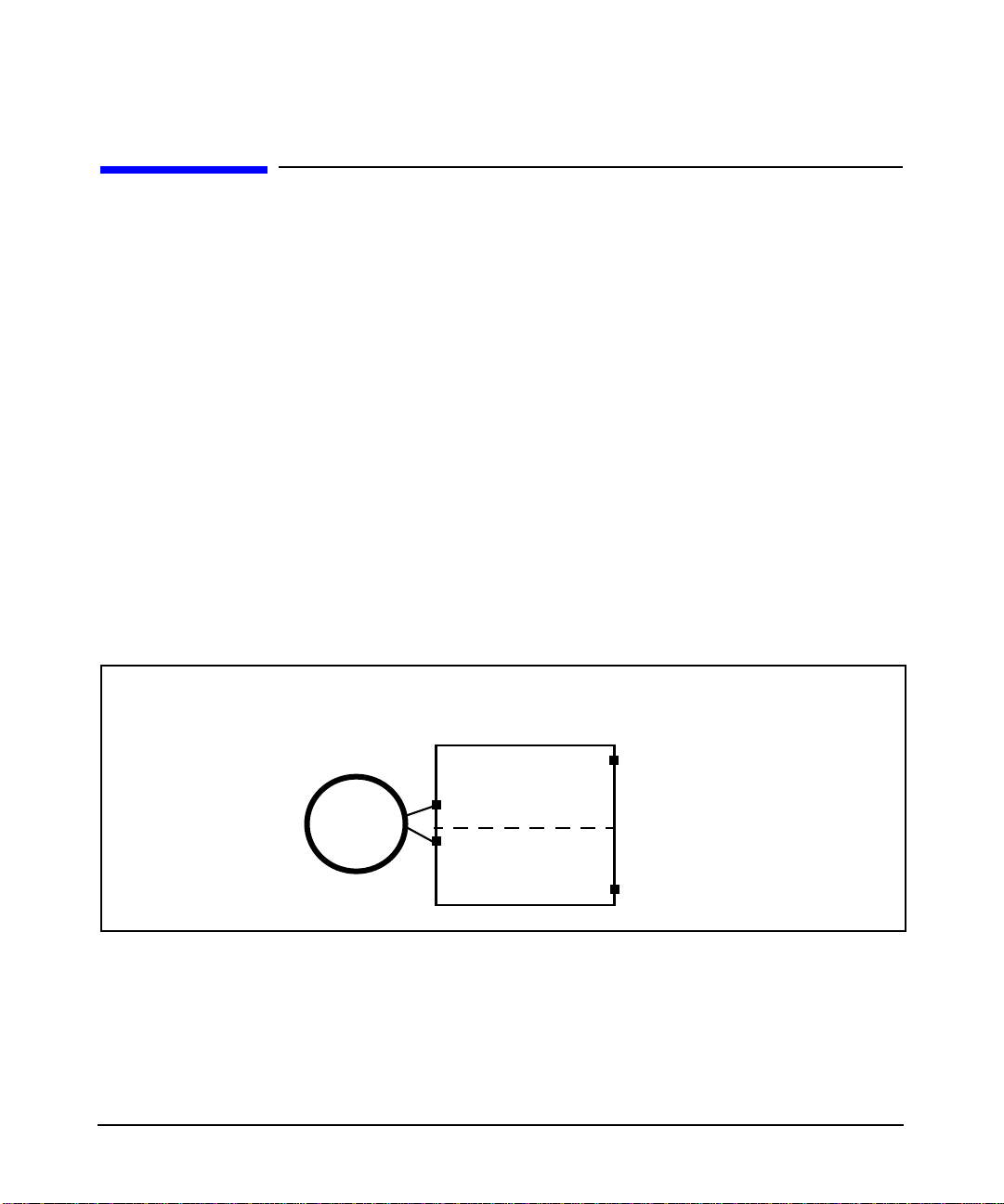
You can create MC ServiceGuard fail-over groups with VLANs as long as
the primary and standby links are both VLAN interfaces with the same
VLAN ID. See Figure 2-2 for an example. Please refer to HP MC
ServiceGuard documentation for more details.
Example:
Figure 2-3 VLANs and Service Guard
Overview of Installation and Configuration
Using VLANs with MC/ServiceGuard
FG2
lan5000
vlanid
1
lan5001
vlanid
2
lan1
FG1 = Fail-over group 1
FG2 = Fail-over group 2
FG3 = Fail-over group 3
FG3
FG1
lan5002
vlanid
1
lan5003
vlanid
2
lan2
Chapter 2 31
Page 32

Overview of Installation and Configuration
How is 802.1p Priority Set?
How is 802.1p Priority Set?
IP packets are classified and marked into different priority levels and the
markings are transported through a type of service (ToS) octet in the
IPv4 header and a traffic class field in the IPv6 header.
HP-UX end stations transmit IPv4 type-of-service (ToS) values but do
not enforce priority. The end stations perform ToS-to-802.1p conversion
and vice-versa for IP packets depending on how the VLAN overrides are
set. They also allow 802.1p priority setting for non-IP packets.
Priority may be set by user, destination address, input port, output port,
access priority, or by VLAN. User priority is a 3-bit field which allows
priority information to be encoded in the frame. The eight levels of IEEE
802.1p recommended user priorities are shown in Table 2-3.
Table 2-3 ToS to 802.1 User Priority Mappings Based on IP Precedence
HP WebQoS ToS
Value Range
0xE0 - 0xFF 7 (highest) Network Management
0xC0 - 0xDF 6 Voice
0xA0 - 0xBF 5 Video
0x80 - 0x9F 4 Controlled Load
0x60 - 0x7F 3 Excellent Effort
0x40 - 0x5F 0 (routine
0x20 - 0x3F 2 Undefined
0x00 - 0x1F 1 (lowest) Background
IEEE 802.1p
User
Priority
traffic)
Traffic Type
Best Effort
Chapter 232
Page 33

Overview of Installation and Configuration
How do Pri and ToS Override Affect My Inbound and Outbound frames?
How do Pri and ToS Override Affect My
Inbound and Outbound frames?
Consider the following command.
lanadmin -V create vlanid
PO
tos_overrideTO 6
This command will create a VLAN interface on PPA 6, with VID as the
VLAN ID, PRI as the 802.1p priority, TOS as the IPv4 ToS value.
• All frames transmitted via the newly created interface will be VLAN
tagged.
• The VLAN ID field in the tag will be VID without exception.
• Please note that non-IP packets are not affected by PO, TO, and TOS
settings. Outbound non-IP packets are always tagged with VLAN ID
VID and 802.1p priority PRI.
The following information applies only to inbound and outbound IP
traffic.
• The 802.1p priority value in the VLAN tag is determined by the PRI,
PO, and TOS settings as shown in Table 2-4.
• The ToSvalue of an inbound IP packet header is determined by TOS,
TO, and PRI settings as shown in Table 2-5.
Table 2-4 Allowable Settings for VLAN_PRI_OVERRIDE
Value in vlanconf File
Priority Override Setting Outbound IP Packets
VID
pri
PRI
tos
TOS
pri_override
CONF_PRI (default) VLAN Tag priority setting is PRI.
IP_HEADER VLAN Tag priority comes from
ToS to 802.1p mapping table (see
Table 2-3). The ToS value is taken
from the IP header.
Chapter 2 33
Page 34

Overview of Installation and Configuration
How do Pri and ToS Override Affect My Inbound and Outbound frames?
Table 2-4 Allowable Settings for VLAN_PRI_OVERRIDE
Value in vlanconf File (Continued)
Priority Override Setting Outbound IP Packets
CONF_TOS VLAN Tag priority comes from
ToS to 802.1p mapping table (see
Table 2-3). The ToS value used is
TOS.
Table 2-5 Allowable Settings for
VLAN_TOS_OVERRIDE Value in vlanconf
File
ToS Override Setting
IP_HEADER (default) IP header ToS value is
CONF_TOS IP header ToS value is
ETHER_HEADER IP header ToS value is
CONF_PRI IP header ToS value is
Inbound IP Packet Header
ToS Setting
undisturbed.
overwritten with TOS
overwritten with a value from the
802.1p to ToS mapping table (see
Table 2-3). The 802.1p value used
comes from the VLAN tag of the
inbound frame.
overwritten with a value from the
802.1p to ToS mapping table (see
Table 2-3). The 802.1p value used
is PRI.
Chapter 234
Page 35

Overview of Installation and Configuration
Setting 802.1p Priority, ToS, and Overrides
Setting 802.1p Priority, ToS, and Overrides
802.1p priority is the priority in the tag in the frame header. Switches
can use the 802.1p priority.
ToS is the IP precedence in the IP header. Switches ignore ToS. Routers
may use it.
The Priority Override Levels for Outbound Traffic are as follows:
CONF_PRI Your specified priority will be used.
IP_HEADER IP header ToS will be converted to 802.1p priority.
CONF_TOS Your specified ToS value will be converted to 802.1p
priority according to the values shown in Table 2-1.
The ToS Override Levels for Inbound Traffic are as follows:
IP_HEADER ToS value in the IP header will be used.
ETHER_HEADER Ether header 802.1p priority will be
converted to ToS value.
CONF_TOS ToS specified by user will used.
CONF_PRI Your specified 802.1p priority will be converted
to ToS.
Where to Get More Information
For information on using the lanadmin command to temporarily modify
HP-UX VLANs (between reboots), type:
man vlan.
Chapter 2 35
Page 36

Overview of Installation and Configuration
Where to Get More Information
Chapter 236
Page 37

3 Configuring VLANs Using SAM
Chapter 3 37
Page 38

Configuring VLANs Using SAM
Configuring VLANs Using SAM
Configuring VLANs Using SAM
You can use SAM to configure VLANs by completing the following steps:
1. Log in as root.
2. Check the HP-UX version by typing: uname -a. The version should
be HP-UX 11i (11.11)
3. At the HP-UX prompt, type: sam
4. At the SAM main window, double click:
Networking and Communications
5. There are then 2 ways to access VLAN configuration. Either choose
the icon Virtual LAN, or choose Network Interface Cards and
then show the VLANs by using the List Pulldown.
SAM displays a list of VLAN-aware physical interfaces and all
VLANs created on them (Figure 3-1).
Figure 3-1 List Pulldown with Virtual LANs Displayed
Chapter 338
Page 39

Configuring VLANs Using SAM
Configuring VLANs Using SAM
6. On the Virtual LAN screen, available VLAN-aware cards are
displayed. When you select a LAN card and then use the Create
VLAN pulldown (Figure 3-2), the Create VLAN screen appears (Figure
3-3). Forthe VLAN ID, enter any number between 0 and 4094 and use
it only once within that port.
NOTE The VLAN ID is not the same as the number of VLANs supported
--HP-UX supports up to 1024 VLANS per LAN card port.
Figure 3-2 Action Pulldown for Creating Virtual LANs
On this screen, you can optionally add a VLAN Name (31 chars, and
unique within a LAN card), priority, ToS, and overrides. See the
chapter “Overview of Installation and Configuration:” or the online
help for details.
Chapter 3 39
Page 40

Configuring VLANs Using SAM
Configuring VLANs Using SAM
Figure 3-3 Create Virtual LANs
After you have assigned a VLAN ID, the VLAN then shows on the
main screen with the status Not Configured. Youthen highlight the
VLAN, and select the Configure IP Address pulldown action. This
displays the Add an IP Address for the VLAN screen (Figure 3-4).
After you have configured an IP address for the VLAN, its status on
the main screen will show as Enabled.
Assign VLAN IDs to each VLAN. Ensure that the assignments are
consistent across endstations and switches; otherwise, stations will
not communicate with each other.
NOTE On a switch or end-station, all the frames for a specific VLAN must
be either tagged or untagged. All devices in a VLAN’s data path must
be VLAN-aware (one that understands VLAN membership and
formats).
Once a VLAN has been configured, you can modify its properties
even if it is in the Enabled state.
Chapter 340
Page 41

On the Modify VLAN Properties screen, the fields are all optional;
the data elements are the same as discussed in the chapter
“Overview of Installation and Configuration:” VLAN name, VPPA,
priority, ToS, and overrides.
Figure 3-4 Add an IP Address for the VLAN
Configuring VLANs Using SAM
Configuring VLANs Using SAM
7. At any time, view the online help pulldown menu for doing any of the
listed tasks or for finding help on a specific field.
Chapter 3 41
Page 42

Configuring VLANs Using SAM
Configuring VLANs Using SAM
Chapter 342
Page 43

4 Configuring VLANs by Editing
vlanconf File
Chapter 4 43
Page 44

Configuring VLANs by Editing vlanconf File
Modifying Parameters in vlanconf File
Modifying Parameters in vlanconf File
Following is the format of the /etc/rc.config.d/vlanconf file. To
permanently save changes to this file, either use SAM or use a text editor
such as “vi.” If you use the lanadmin command line interface to make
changes to VLANs, your configuration will not be preserved after reboots
unless you modify the vlanconf file manually.
# vlanconf: configuration values to create VLAN Virtual
# Interface. This file will maintain the VLAN
# information across reboot, and will be modified
# by SAM. You can also edit this file.
#
# VLAN_PHY_INTERFACE : Physical interface name, see
# lanscan(1m)output. This value must be
# specified.
#
# VLAN_ID : Unique VLAN id for VLAN. VLAN id is a
# positive integer value which can range
# from 0 to 4094. This value must be
# specified.
#
# VLAN_PRIORITY : Priority for the VLAN. Priority is
# a positive integer value which can
# range from 0 to 7. Default value of 0
# will be taken if not specified.
#
# VLAN_TOS : Inbound ToS value applicable to IP
# packets. Its a positive integer value
# that ranges from 0 to 255. A default
# value of 0 will be taken if not
# specified.
#
# VLAN_PRI_OVERRIDE : Outbound priority override level. It
# tells the system what priority to
# choose, when tagging the packets with
# VLAN information.Allowed priority
# override levels are as follows:
#
# CONF_PRI - User specified priority
# will be used (default if
# not specified).
# IP_HEADER - IP header ToS will be
# converted to 802.1p
Chapter 444
Page 45

Configuring VLANs by Editing vlanconf File
Modifying Parameters in vlanconf File
# priority. Only for
# IP packets. For non-IP
# packets, CONF_PRI
# will be used.
# CONF_TOS - User specified ToS, taken
# from VLAN_TOS[] will be
# converted to
# 802.1p priority.
#
# VLAN_TOS_OVERRIDE : Inbound ToS value to be used for IP
# packets.
# Allowed ToS override levels are as follows:
#
# IP_HEADER - ToS value in the IP
# header will be used
# (default if not
# specified).
# ETHER_HEADER - Ether header 802.1p
# priority will be
# converted to ToS
# value.
# CONF_TOS - ToS specified by the user
# will be used.
# CONF_PRI - 802.1p priority given in
# VLAN_PRIORITY[] will
# be converted to ToS
# value.
#
# VLAN_NAME : Name of the VLAN. Its a simple string,
# which consists of alphanumeric
# characters. No special characters
# allowed.
#
# VLAN_VPPA : User requested VPPA for the VLAN Virtual
# Interface that will be created by the
# information given above. If not
# specified system will assign a VPPA.
#
#
# For each VLAN configuration, add a set of variable # assignments like the ones
below, changing the index to “[1]”, # “[2]” et cetera.
##############################################################
#
# Sample Entry
#
# VLAN_PHY_INTERFACE[1]=
Chapter 4 45
Page 46

Configuring VLANs by Editing vlanconf File
Modifying Parameters in vlanconf File
# VLAN_ID[1]=
# VLAN_PRIORITY[1]=
# VLAN_TOS[1]=
# VLAN_PRI_OVERRIDE[1]=
# VLAN_TOS_OVERRIDE[1]=
# VLAN_NAME[1]=””
# VLAN_VPPA[1]=
Example:
Following is an example where the physical interface lan0 has been
assigned a VLAN ID of 1, default values for VLAN priority, VLAN ToS,
VLAN priority override, VLAN ToS override, the name “Red,” and a
VLAN PPA of 5000.
VLAN_PHY_INTERFACE[0]=lan0
VLAN_ID[0]=1
VLAN_PRIORITY[0]=0
VLAN_TOS[0]=0
VLAN_PRI_OVERRIDE[0]=CONF_PRI
VLAN_TOS_OVERRIDE[0]=IP_HEADER
VLAN_NAME[0]=Red
VLAN_VPPA[0]=5000
Chapter 446
Page 47

Using lanadmin -V to Administer VLANs
5 Using lanadmin -V to
Administer VLANs
Chapter 5 47
Page 48

Using lanadmin -V to Administer VLANs
Using the lanadmin -V Command for Administering VLANs
Using the lanadmin -V Command for
Administering VLANs
To configure VLANs, you use either the GUI-based system admin
manager (SAM) or edit the configuration file with an editor. VLAN
configuration doesn’t require a reboot to take effect. If you use SAM, your
configurations will be preserved after reboots in a configuration file
called /etc/rc.config.d/vlanconf.
If you use the lanadmin command line interface, your configuration will
not be preserved after reboots unless you also save the configuration in
the vlanconf file by either using SAM or editing it. See “Modifying
Parameters in vlanconf File” in this document for the format of the
/etc/rc.config.d/vlanconf file.
lanadmin Syntax
If you use the lanadmin command line interface to work with VLANs,
you can display the general usage string by typing:
lanadmin -V help
General usage string:
lanadmin -V create vlanid <vlanid> (range 0-4094)
[pri <priority> (range 0 - 7, default 0)]
[tos <ToS value> (range 0-255, default 0)]
[vppa <vppa>]
[name <name> (31 characters alphanumeric
string)]
[tos_override <level>(IP_HEADER, ETHER_HEADER,
CONF_TOS or CONF_PRI,
default IP_HEADER)]
[pri_override <level>(CONF_PRI,IP_HEADER
or CONF_TOS, default CONF_PRI)] <ppa>
-V delete <vppa>
-V modify [vlanid <vlanid> (range 0-4094)]
[pri <priority> (range 0 - 7)]
[tos <ToS value> (range 0-255)]
[name <name> (31 characters alpha numeric
string]
[tos_override <level>(IP_HEADER, ETHER_HEADER,
Chapter 548
Page 49

Using lanadmin -V to Administer VLANs
Using the lanadmin -V Command for Administering VLANs
CONF_TOS or CONF_PRI)
[pri_override <level>(CONF_PRI,IP_HEADER or
CONF_TOS)] <vppa>
-V scan
-V info <vppa>
-V basevppa
-V help
Using lanadmin to Create a VLAN
Assume that the system has the following configuration as shown by the
lanscan command output.
lanscan
Hardware Station Crd Hdw Net-Interface NM MAC HP-DLPI DLPI
Path Address In# State NamePPA ID Type Support Mjr#
1/2/3 0x001083FF9951 0 UP lan0 snap0 1 ETHER Yes 119
1/2/4 0x006023456789 1 DOWN lan1 snap1 2 ETHER Yes 119
To configure a VPPA with VLAN ID 454 and a priority of 6 on “lan0”,
execute the following command.
lanadmin -V create vlanid 454 pri 6 0
Successfully configured
lan5000: vlanid 454 name UNNAMED pri 6 tos 0 tos_override IP_HEADER pri_override
CONF_PRI ppa 0
This command created a VLAN “lan5000” on top of the physical interface
lan0. The PPA associated with this VLAN, 5000, is referred to as a
VPPA, short for Virtual PPA. Note: the parameters that were not
specified in the command have been assigned default values.
Displaying a VLAN and its Properties
You can use the default lanscan command to view all the interfaces as
follows.
lanscan
VLAN0 0x001083FF9951 5000 UP lan5000snap5000 14 ETHER Yes 119
1/2/4 0x006023456789 1 DOWN lan1 snap1 2 ETHER Yes 119
Chapter 5 49
Page 50

Using lanadmin -V to Administer VLANs
Using the lanadmin -V Command for Administering VLANs
The VLAN (lan5000) appears in lanscan output just like a physical
interface. VPPAs are identified by the string “VLANx” in the hardware
path, where x is a number and is unique per VPPA. In the lanscan
output, VPPAs of a given physical interface are displayed just after the
corresponding physical interface.
The verbose option of the lanscan command displays more information
about the VLAN.
lanscan -v
Hardware Station Crd Hdw Net-Interface NM MAC HP-DLPI DLPI
Path Address In# State Name PPA ID Type Support Mjr#
VLAN0 0x001083FF9951 5000 UP lan5000 snap5000 14 ETHER Yes 119
Extended Station LLC Encapsulation
Address Methods
0x001083FF9951
Driver Specific Information
vlan
.......................................................................
Vlan ID Phy-PPA Priority ToS Priority-Override ToS-Override Name
454 0 6 0 CONF_PRI IP_HEADER UNNAMED
Using lanadmin to Set 802.1p Priority, ToS, and Overrides
The lanadmin -V create vlanid command has options to set the
802.1p priority, called pri, and/or the Type of Service (ToS) value, called
tos. It also has pri_override and tos_override. For more details, refer to
“Setting 802.1p Priority, ToS, and Overrides” in this document.
Using lanadmin to Query for VLANs on a System
The following command can be used to query for the list of VPPAs
configured and their properties.
lanadmin -V scan
A sample output for the successful command is as follows:
VLAN Physical VLAN Pri Pri ToS ToS NAME
Interface Interface ID Override Override
Name Level Level
lan5000 lan0 5 2 CONF_PRI 25 IP_HEADER
lan5003 lan0 11 5 CONF_PRI 204 CONF_PRI purple
lan5001 lan1 1 4 IP_HEADER 64 IP_HEADER newone
lan5002 lan2 3 7 CONF_TOS 200 CONF_PRI UNNAMED
Note: UNNAMED will be displayed as the VLAN name if there is no
name associated with the VPPA.
Chapter 550
Page 51

Using lanadmin -V to Administer VLANs
Using the lanadmin -V Command for Administering VLANs
Querying for a Single VPPA on a System You can query the Virtual
PPA using the following command:
lanadmin -V info <vppa>
The info command will return the output in the following format when
successful.
Example: lanadmin -V info 5000
VLAN Physical VLAN Pri Pri ToS ToS NAME
Interface Interface ID Override Override
Name Level Level
lan5000 lan0 5 2 CONF_PRI 25 IP_HEADER
Querying for a Base VPPA Value You can determine the minimum
acceptable value for a Virtual PPA using the following command:
lanadmin -V basevppa
Example: lanadmin -V basevppa
5000
Using a VLAN
Once a VLAN is created, its VPPA can be used to configure protocols,
send commands, and transmit and receive data just like a physical point
of attachment (PPA). For example, to configure an IP address on the
VLAN, type:
ifconfig lan5000 inet 100.2.1.1 netmask 255.255.255.0 up
NOTE You cannot change physical link properties such as speed, duplexity, or
maximum transmission unit (MTU) over a VLAN. If you make changes
to a physical interface, those changes will be reflected in the VLANs on
that interface.
Using lanadmin to Modify a VLAN
The properties of a VLAN can be modified using lanadmin. For example,
to change the VLAN ID to 53 and priority to 3, on lan5000, type:
Chapter 5 51
Page 52

Using lanadmin -V to Administer VLANs
Using the lanadmin -V Command for Administering VLANs
lanadmin -V modify vlanid 53 pri 3 5000
Successfully modified lan5000
Old value: vlanid 454 pri 6
New value: vlanid 53 pri 3
After the modification, the lanscan -v output will display:
Hardware Station Crd Hdw Net-Interface NM MAC HP-DLPI DLPI
Path Address In# State NamePPA ID Type Support Mjr#
VLAN0 0x001083FF9951 5000 UP lan5000 snap5000 14 ETHER Yes 119
Extended Station LLC Encapsulation
Address Methods
0x001083FF9951
Driver Specific Information
vlan
.......................................................................
Vlan ID Phy-PPA Priority ToS Priority-Override ToS-Override Name
53 0 3 0 CONF_PRI IP_HEADER UNNAMED
Using lanadmin to Delete a VLAN
Before deleting a VLAN, ensure that there are no applications or upper
layer protocols active on the VLAN by running:
lanadmin -p <VPPA>.
This command displays the applications and commands that are
presently using the interface. For example, if the only thing done to
lan5000 is configure an IP address, the lanadmin -p command output
would look like:
lanadmin -p 5000
ifconfig
ifconfig
Since ifconfig command is used to configure an IP address the same is
displayed. There are two entries because when an IPv4 address is
configured using ifconfig, it configures both IP and ARP on the
interface.
To remove the IP and ARP streams, do:
ifconfig lan5000 unplumb.
The lanadmin -p 5000 output will not show any entries now, which
means the interface can be deleted. To delete this VLAN use the delete
option as follows:
Chapter 552
Page 53

Using lanadmin -V to Administer VLANs
Using the lanadmin -V Command for Administering VLANs
lanadmin -V delete 5000
The lanadmin -p <PPA>, command always displays the displays the
applications and commands that use or are configured on the interface.
Lets take another example. Before deleting, the interface lan5001, check
if there are any applications running on it by typing:
lanadmin -p 5001
ifconfig
ifconfig
mib2agt
scopeux
In addition to IP and ARP being configured on the interface, two
applications, mib2agt and scopeux, are using the interface. These
applications are started during system bootup via the startup scripts
/sbin/rc2.d/S565SnmpMib2 and /sbin/rc2.d/S810mwa respectively. To
stop these utilities, run the stop sequence of the scripts. To delete the
lan5001 interface, type the following commands:
ifconfig lan5001 unplumb
/sbin/rc2.d/S565SnmpMib2 stop
/sbin/rc2.d/S810mwa stop
Now, lanadmin -p 5001 will not display anything, and the interface can
be deleted using lanadmin -V delete
Once the interface is deleted, you can restart the script by issuing the
start sequence:
/sbin/rc2.d/S565SnmpMib2 start
/sbin/rc2.d/S810mwa start
NOTE: The start and stop sequence of the startup scripts will affect all
the interfaces on the system, and they must be restarted once the delete
operation is completed.
The output from the commands just described may not look exactly the
same on your system. The output can vary depending on the applications
using the interfaces in your environment.
Chapter 5 53
vppa
.
Page 54

Using lanadmin -V to Administer VLANs
Using the lanadmin -V Command for Administering VLANs
Chapter 554
Page 55

A Troubleshooting
Appendix A 55
Page 56

Troubleshooting
This chapter provides guidelines for troubleshooting VLANs. It contains
the following sections:
• Diagnostic Flowcharts.
• Use of lanadmin and lanscan commands and scripts for testing or
troubleshooting VLANs.
Appendix A56
Page 57

Troubleshooting
Diagnostic Flowcharts
Diagnostic Flowcharts
Table A-1 summarizes the types of network tests in the diagnostic
flowcharts. Follow the flowcharts in sequence beginning with Flowchart
1.
Table A-1 Flowchart Descriptions
Chart Type of Test Purpose
1 Link Level Tests Checks communications between link levels. Verifies VLAN
creation.
1a linkloop Test Verifies link-level address of remote hosts.
1b lanscan,
lanadmin Tests
2 Network Level
Tests
2a ARP Test Verifies that an entry exists for the remote host in your
2b ping Test Checks roundtrip communication between Network Layers
Verifies VLAN IDs and tests VLAN creation.
Validate ARP(1M) entries and remote host availability.
Check communication between network layers on source
and target host.
system's ARP cache.
on the source and target host.
Appendix A 57
Page 58

Troubleshooting
Flowchart 1: Link Level Tests
Flowchart 1: Link Level Tests
Check communications between link levels on the source and target host
using the linkloop , lanscan, and lanadmin commands. The source
interface should be a VPPA, that is, a PPA corresponding to a VLAN
interface. The destination MAC address is the remote VPPA’s MAC
address.
Appendix A58
Page 59

Figure A-1 Flowchart 1
Troubleshooting
Flowchart 1: Link Level Tests
Link Level
Tests
linkloop Test
lanscan and lanadmin
Tests
Appendix A 59
Page 60

Troubleshooting
Flowchart 1: Link Level Tests
Flowchart 1a: Linkloop Test
Figure A-2 Flowchart 1a
Linkloop
Test
Execute
linkloop to
remote host
Loopback FAILED;
Address has bad
format or
Not an individual
address
Correct the link
address parameter
Link Level
Test
Linkoop
YES
Network-Level
successful?
NO
Loopback FAILED;
remote host fails
to respond
Re-check remote host address
and if
same VLAN ID is enabled,
choose a different
remote host and
re-execute linkloop
Linkoop
NO
lanscan/lanadmin
successful?
YES
Tests
Tests
Network
Test
Appendix A60
Page 61

Troubleshooting
Flowchart 1: Link Level Tests
Flowchart 1a Procedures
• Execute linkloop to remote host. If linkloop is successful, continue
to Network Test. Else if linkloop fails note which error was returned.
• If loopback failed error = “Address has bad format” or “not an
individual address” then correct the link level address with the
proper station address format/value and repeat the Link Level Test.
• Otherwise, loopback failed because the remote host did not respond.
Double check the remote host address and VLAN ID, or choose
another remote host and re-execute linkloop.
— Ensure VLAN IDs are the same by using lanadmin -V scan on
both the source and destination.
— Ensure switches along the path are configured with the correct
VLAN ID and marked “tagged” or “untagged” as appropriate.
— Ensure MTUs match as well.
— Ensure that link parameters for autonegotiation, flow control
speed and duplexity are compatible.
— Ensure that the link is up. Refer to the documentation for each
specific link for details.
If linkloop is successful, continue to Network Test. You may also
want to contact the node manager of the remote that did not respond
(if this was the case).
Appendix A 61
Page 62

Troubleshooting
Flowchart 1: Link Level Tests
Flowchart 1b: lanscan and lanadmin Test
Figure A-3 Flowchart 1b
lanscan
and
lanadmin
Test
Is your interface
displayed after
executing
lanscan?
NO
Create VLAN
by running
lanadmin -V create
YES
Problem
fixed?
YES
Stop
YES
NO
Run
Execute
lanscan -v
Is VLAN ID
correct?
NO
Modify VLAN
by running
lanadmin -V modify
Any
YES
error
messages?
YES
Correct
the
problem
YES
NO
Network-Level
Tests
Network-Level
Tests
Appendix A62
Page 63

Troubleshooting
Flowchart 1: Link Level Tests
Flowchart 1b Procedures
• Execute lanscan command and verify your interface is displayed by
the system.
— If it is displayed, run lanscan -v to ensure the VLAN ID is
correct. If so, return to the network Test. If not, modify the
VLAN to the correct one by running the command
lanadmin -V modify.
— If the interface is not displayed, run lanadmin -V create to
create the VLAN.
• If the problem is fixed, Stop. Else, check for any error messages.
— If there are error messages correct them according to the error
message.
— If there are no error messages, return to the network Test.
Appendix A 63
Page 64

Troubleshooting
Flowchart 2: Network Level Tests
Flowchart 2: Network Level Tests
Figure A-4 Flowchart 2
Network
Level
Tests
ARP Test
ping Test
Appendix A64
Page 65

Troubleshooting
Flowchart 2: Network Level Tests
Flowchart 2 Procedures
• See Flowchart 2a to validate ARP entries and remote host
availability.
• See Flowchart 2b to check communication between network layers on
source and target host using ping.
Appendix A 65
Page 66

Troubleshooting
Flowchart 2: Network Level Tests
Flowchart 2a: ARP Test
Figure A-5 Flowchart 2a
ARP Test
Is remote host
entry in ARP
cache?
YES
Is the ARP
entry correct
and complete
?
YES
ping Test
NO
NO
Remote
host up?
NO
Bring up
remote host
Use ARP to
correct and
complete the
entry
YES
Appendix A66
Page 67

Troubleshooting
Flowchart 2: Network Level Tests
Flowchart 2a Procedures
• Use ARP to verify that an entry exists for the remote host in your
system's ARP cache by executing arp hostname
• If there is no ARP entry for the remote host, check to see if the
remote host is up. If not, bring up remote host and continue to ping
Test.
• If the ARP entry is incorrect or not complete, use ARP to enter the
correct station address of the remote system and continue to ping
Test. Otherwise, continue to ping Test.
Appendix A 67
Page 68

Troubleshooting
Flowchart 2: Network Level Tests
Flowchart 2b: ping Test
Figure A-6 Flowchart 2b
ping Test
Execute
ping remotehost
YES
ping
successful?
YES
Stop
Validate network,
NO
remote host, and
configuration
continued
settings
Appendix A68
Page 69

Troubleshooting
Flowchart 2: Network Level Tests
Flowchart 2b Procedures
• Execute ping to remote host using ping.
• If ping is successful, stop. If not, validate network, remote host, and
configuration settings. Verify the routing tables using the netstat
-rn command.
Appendix A 69
Page 70

Troubleshooting
Flowchart 2: Network Level Tests
Flowchart 2b (continued):
Figure A-7 Flowchart 2b (continued)
ping not
successful
Network
unreachable?
error?
NO
No response
from ping?
NO
Unknown host
error?
NO
No route to
host error?
YES
Network-Level
YES
YES
YES
Tests
Link-Level
Tests
Correct BIND, YP,
or /etc/hosts
configuration
ping
Test
Add route
table entry
Call HP
NO
Appendix A70
Page 71

Troubleshooting
Flowchart 2: Network Level Tests
Flowchart 2b (continued) Procedures
• If network unreachable error, go to the Configuration Tests.
• If no response from ping, validate switches in path support VLANs
and remote host supports them as well. Otherwise, reconfigure
network path, or configure VLANs on remote host and/or switches
then repeat ping Test. Return to linkloop test.
• If you receive an unknown hosts error, add the missing host name
and repeat ping Test.
• If you receive “error=SendTo: No route to host”, then using route
add route table entry for the missing host and repeat ping Test.
Otherwise, call HP.
Appendix A 71
Page 72

Troubleshooting
NetTL Trace and Log of VLANs
NetTL Trace and Log of VLANs
The nettl tool can be used to troubleshoot VLANs. Following is a sample
trace output from a Gigabit Ethernet card:
Tracing Output from a Gigabit Ethernet Card
^^^^^^^^^^^^^^^^^^^^^^Gigabit Ethernet LAN/9000 Networking^^^^^^^^^^^^^^^^^^
Timestamp : Wed Nov 07 PST 2001 11:08:03.961449
Process ID : [ICS] Subsystem : GELAN
User ID ( UID ) : -1 Trace Kind : PDU IN TRACE
Device ID : 1 Path ID : -1
Connection ID : 0
Location : 00123
~~~~~~~~~~~~~~~~~~~~~~~~~~~~~~~~~~~~~~~~~~~~~~~~~~~~~~~~~~~~~~~~~~~~~~~~~~~~
=================================== Ethernet====================================
Source : 00-10-83-05-16-7e [I] [ ]
Dest : 00-10-83-05-16-7d [I] [ ] TRACED LEN: 1480
VLAN ID: 0x4 Priority: 0x2 CFI: 0x0
Date : Wed Nov 07 11:08:03.961449 PST 2001
================================ IP Header (inbound -- [ICS]) ================
Source: 101.3.102.47(A) Dest: 101.3.102.61(A)
len: 1462 ttl: 255 proto: 1 cksum: 0x218a id: 0xbe49
flags: DF tos: 0x0 hdrlen: 20 offset: 0x0 optlen: 0
-------------------------------- ICMP Header --------------------------------type: ECHOREPLY chksum: 0x779c id: 29129 seq: 2
code: none
-------------------------------- User Data -----------------------------------
0: 3b e9 86 6d 00 06 ab cc 08 09 0a 0b 0c 0d 0e 0f ;..m............
16: 10 11 12 13 14 15 16 17 18 19 1a 1b 1c 1d 1e 1f ................
32: 20 21 22 23 24 25 26 27 28 29 2a 2b 2c 2d 2e 2f !"#$%&'()*+,-./
48: 30 31 32 33 34 35 36 37 38 39 3a 3b 3c 3d 3e 3f 0123456789:;<=>?
64: 40 41 42 43 44 45 46 47 48 49 4a 4b 4c 4d 4e 4f @ABCDEFGHIJKLMNO
80: 50 51 52 53 54 55 56 57 58 59 5a 5b 5c 5d 5e 5f PQRSTUVWXYZ[\]^_
96: 60 61 62 63 64 65 66 67 68 69 6a 6b 6c 6d 6e 6f `abcdefghijklmno
112: 70 71 72 73 74 75 76 77 78 79 7a 7b 7c 7d 7e 7f pqrstuvwxyz{|}~.
128: 80 81 82 83 84 85 86 87 88 89 8a 8b 8c 8d 8e 8f ................
.........
.......
1424: 90 91 92 93 94 95 96 97 98 99 -- -- -- -- -- -- ................
^^^^^^^^^^^^^^^^^^^^^^Gigabit Ethernet LAN/9000 Networking^^^^^^^^^^^^^^^^^^
Timestamp : Wed Nov 07 PST 2001 11:08:03.961449
Process ID : [ICS] Subsystem : GELAN
User ID ( UID ) : -1 Trace Kind : PDU IN TRACE
Appendix A72
Page 73

Troubleshooting
NetTL Trace and Log of VLANs
Device ID : 1 Path ID : -1
Connection ID : 0
Location : 00123
~~~~~~~~~~~~~~~~~~~~~~~~~~~~~~~~~~~~~~~~~~~~~~~~~~~~~~~~~~~~~~~~~~~~~~~~~~~~
Received 1480 bytes via Ethernet Wed Nov 07 11:08:03.961449 PST 2001
pid=[ICS] interface=[1]
Dest: 00-10-83-05-16-7d Source: 00-10-83-05-16-7e
00-10-83-05-16-7e VLAN Tag: 0x4004
0: 45 00 05 b6 be 49 40 00 ff 01 21 8a 65 03 66 2f E....I@...!.e.f/
16: 65 03 66 3d 00 00 77 9c 71 c9 00 02 3b e9 86 6d e.f=..w.q...;..m
32: 00 06 ab cc 08 09 0a 0b 0c 0d 0e 0f 10 11 12 13 ................
48: 14 15 16 17 18 19 1a 1b 1c 1d 1e 1f 20 21 22 23 ............ !"#
64: 24 25 26 27 28 29 2a 2b 2c 2d 2e 2f 30 31 32 33 $%&'()*+,-./0123
80: 34 35 36 37 38 39 3a 3b 3c 3d 3e 3f 40 41 42 43 456789:;<=>?@ABC
96: 44 45 46 47 48 49 4a 4b 4c 4d 4e 4f 50 51 52 53 DEFGHIJKLMNOPQRS
112: 54 55 56 57 58 59 5a 5b 5c 5d 5e 5f 60 61 62 63 TUVWXYZ[\]^_`abc
128: 64 65 66 67 68 69 6a 6b 6c 6d 6e 6f 70 71 72 73 defghijklmnopqrs
.........
.........
864: 44 45 46 47 48 49 4a 4b 4c 4d 4e 4f 50 51 52 53 DEFGHIJKLMNOPQRS
1456: 94 95 96 97 98 99 -- -- -- -- -- -- -- -- -- -- ................
Logging Example
If you try to create a VLAN with a VLANID that is already present on
the physical PPA you get the following output in verbose formatting
mode:
*********************************VLAN Subsystem*****************************
Timestamp : Wed Nov 07 PST 2001 11:23:44.311001
Process ID : 8631177 Subsystem : VLAN
User ID ( UID ) : 0 Log Class : ERROR
Device ID : -1 Path ID : 0
Connection ID : 0 Log Instance : 0
~~~~~~~~~~~~~~~~~~~~~~~~~~~~~~~~~~~~~~~~~~~~~~~~~~~~~~~~~~~~~~~~~~~~~~~~~~~
<2003> Create: User specified VLANID 53 is already in use by another VLAN.
(Error) The VLANID specified is already in use by another
VLAN created on the same physical interface(PPA). Choose
another VLANID or try creating the VLAN on another
physical interface(PPA).
Appendix A 73
Page 74

Troubleshooting
NetTL Trace and Log of VLANs
Appendix A74
Page 75

Glossary
802.1p: IEEE Standard supplement, now
incorporated in IEEE 802.1D. Defines 8
priority levels for traffic classification at the
data link level and suggests how they might
be used.
802.1Q: IEEE Standard that specifies the
architecture for VLAN tagging, association,
and VLAN-capable bridges.
100Base-T: A 100 Mbit/s communication
method specified in the IEEE 802.3u-1995
standard. The official name for Fast
Ethernet.
Alias: Name of the interface that
corresponds to a given Internet address on a
system.
Canonical format indicator: The CFI bit
indicates that all MAC addresses present in
the MAC data field are in canonical
format.HP-UX always transmits a CFI of 0.
Card Instance Number: A number that
uniquely identifies a device within a class. A
class of devices is a logical grouping of
similar devices.
CoS: Class of Service. The ability to provide
different levels of service to various traffic
flows. A flow may be determined explicitly
via tags or implicitly from the frame
contents (such as the IP address or ToS
field). Class of Service (CoS) network
management is when similar types of traffic
(for example, voice, video, or data) are
grouped together and assigned a priority.
Unlike Quality of Service (QoS) traffic
management, CoS does not guarantee a level
of service in terms of bandwidth and delivery
time.
Destination Address: A field in the
message packet format identifying the end
node(s) to which the packet is being sent.
Ethernet: A 10 Mbit/s LAN, developed by
Digital Equipment Corporation, Intel, and
Xerox Corporation, upon which the IEEE
802.3 network is based.
Fast Ethernet: A commonly used name
applied to 100Base-T.
HSC: High speed connect bus.
Hardware Path: An identifier assigned by
the system according to the physical location
(slot) of a card in the hardware backplane.
Hostname: Name of system on the network.
Hub: A network interconnection device that
allows multiple devices to share a single
logical link segment. Hubs are generally
either 10 Mbit/s or 100 Mbit/s devices.
IEEE: The Institute of Electrical and
Electronics Engineers. A national
association, whose activities include
publishing standards applicable to various
electronic technologies. The IEEE technical
committees are numbered and grouped by
area. Forexample, the 800 committees study
local area network technologies. The 802.3
committee produced the standard for a
CSMA/CD local area network, which has
been adopted by ANSI.
Internet Address: The network address of
a computer node. This address identifies
both which network the host is on and which
host it is. Refer to the Installing and
Administering LAN/9000 Software manual
for detailed information about network
addressing.
Glossary 75
Page 76

Glossary
IP:
IP: Internet protocol.
IP Address: See Internet Address glossary
entry.
QoS: Quality of Service. The ability to
provide guarantees for data transfer -- for
example, latency, throughput, and discard
priority.
LAN: See Local Area Network.
Local Area Network (LAN): A data
communications system that allows a
number of independent devices to
communicate with each other.
Local Network: The network to which a
node is directly attached.
Maximum Transmission Unit (MTU).
Largest amount of data that can be
transmitted through that interface. This
value does not include the LLC or MAC
headers.
NetTL. HP’s tracing and logging facility for
HP-UX networking.
Network Interface: A communication path
through which messages can be sent and
received. A hardware network interface has
a hardware device associated with it, such as
a LAN card. A software network interface
does not include a hardware device, for
example the loopback interface. Forevery IP
address instance, there must be one network
interface configured.
NIC: Network interface card.
PCI: Peripheral component interconnect.
PPA: Physical point of attachment. A PPA is
the point at which a system is attached to a
physical communications medium. All
communication on that physical medium
funnels through the PPA.
SAM: System admin manager. GUI-based
HP tool for system configuration and
management.
Shared media LAN: A local area network
(LAN) that shares all its bandwidth among
all stations.
Switch: A network interconnection device
that allows multiple connected senders and
receivers to communicate simultaneously in
contrast to a hub (repeater) where only one
device can send at a time. Some switches
have fixed port speeds (10 Mbit/s or 100
Mbit/s) while others allow port speeds to be
configured or autonegotiated.
Tag aware: Devices such as switches,
routers, and end-stations that can interpret
VLAN tags. See also VLAN-aware.
TCP: Transmission control protocol.
Topology: The physical and logical
geometry governing placement of nodes in a
computer network. Also, the layout of the
transmission medium for a network.
ToS: IPv4 Type of Service field which
indicates the desired service expected by an
IP packet for delivery through routers across
the IP internetwork. The size of this field is 8
bits,which contain bits for precedence,delay,
throughput, and reliability characteristics.
UTP (Unshielded Twisted Pair)
Cabling: A data cable type consisting of
pairs of wires twisted together without an
electrically shielding jacket.
Glossary76
Page 77

Virtual PPA or VPPA: Virtual Interfaces
which are dynamically created by you (using
lanadmin or SAM). The interfaces are
“virtual” because they do not have a unique
hardware instance. A virtual PPAis the PPA
associated with a VLAN.
VLAN: Virtual LAN.VLANs, are a
mechanism to determine which end stations
should receive broadcast traffic, since it
should not be sent arbitrarily to every
connected user. Each packet transmitted by
an end-station is assigned to a VLAN. An
end-station only receives all the multicast
and broadcast traffic on the LANs to which it
belongs, and an end-station receives unicast
traffic addressed to it on the VLAN to which
it belongs.
VLAN-aware: Devices such as switches and
end-stations that can recognize VLAN tags,
but they do not actually interpret them. See
also tag-aware.
Glossary
VPPA:
VLAN ID: A VLAN ID uniquely identifies
the VLAN to which a frame belongs.
VLAN tag: A 4-byte extension to the MAC
header consisting of a 2-byte VLAN protocol
ID (0x8100) and 2-bytes of tag control
information. VLAN tags enable traffic from
more than one VLAN to use the same port.
VPPA: see Virtual PPA.
Glossary 77
Page 78

Glossary
Virtual PPA or VPPA:
Glossary78
 Loading...