

Page 1

HP Stream Notebook PC
(model numbers 11-r000 through 11-r099)
and HP Stream 11 Pro G2 Notebook PC
Maintenance and Service Guide
IMPORTANT! This document is intended for
HP authorized service providers only.
Page 2

© Copyright 2015 HP Development Company,
L.P.
Bluetooth is a trademark owned by its
proprietor and used by HP Inc. under license.
DTS, the Symbol, & DTS and the Symbol
together are registered trademarks, and DTS
Sound is a trademark of DTS, Inc. © DTS, Inc.
All Rights Reserved. Intel and Celeron are
trademarks of Intel Corporation in the U.S.
and other countries. SD Logo is a trademark of
its proprietor.
The information contained herein is subject to
change without notice. The only warranties for
HP products and services are set forth in
the express warranty statements
accompanying such products and services.
Nothing herein should be construed as
constituting an additional warranty. HP shall
not be liable for technical or editorial errors or
omissions contained herein.
First Edition: September 2015
Document Part Number: 829769-001
Product notice
This guide describes features that are common
to most models. Some features may not be
available on your computer.
Not all features are available in all editions of
Windows 10. This computer may require
upgraded and/or separately purchased
hardware, drivers, and/or software to take full
advantage of Windows 10 functionality. See
for http://www.microsoft.com details.
Page 3

Safety warning notice
WARNING! To reduce the possibility of heat-related injuries or of overheating the device, do not place
the device directly on your lap or obstruct the device air vents. Use the device only on a hard, flat surface. Do
not allow another hard surface, such as an adjoining optional printer, or a soft surface, such as pillows or
rugs or clothing, to block airflow. Also, do not allow the AC adapter to contact the skin or a soft surface, such
as pillows or rugs or clothing, during operation. The device and the AC adapter comply with the useraccessible surface temperature limits defined by the International Standard for Safety of Information
Technology Equipment (IEC 60950).
iii
Page 4

iv Safety warning notice
Page 5

Table of contents
1 Product description ....................................................................................................................................... 1
2 Getting to know your computer ...................................................................................................................... 5
Locating hardware ................................................................................................................................................. 5
Locating software .................................................................................................................................................. 5
Display ................................................................................................................................................................... 6
Buttons ................................................................................................................................................................... 7
Keys ........................................................................................................................................................................ 8
Lights ..................................................................................................................................................................... 9
TouchPad ............................................................................................................................................................. 10
Left side ............................................................................................................................................................... 11
Right side ............................................................................................................................................................. 12
Bottom ................................................................................................................................................................. 13
3 Illustrated parts catalog .............................................................................................................................. 14
Locating the serial number, model number, product number, and warranty information ............................... 14
Computer major components ............................................................................................................................. 15
Display assembly subcomponents ..................................................................................................................... 21
Miscellaneous parts ............................................................................................................................................. 22
4 Removal and replacement preliminary requirements ..................................................................................... 25
Tools required ...................................................................................................................................................... 25
Service considerations ........................................................................................................................................ 25
Plastic parts ....................................................................................................................................... 25
Cables and connectors ...................................................................................................................... 25
Drive handling ................................................................................................................................... 26
Grounding guidelines ........................................................................................................................................... 27
Electrostatic discharge damage ....................................................................................................... 27
Packaging and transporting guidelines ......................................................................... 28
Workstation guidelines ................................................................................ 28
5 Removal and replacement procedures ........................................................................................................... 30
Component replacement procedures ................................................................................................................. 30
Keyboard/top cover .......................................................................................................................... 30
TouchPad board ................................................................................................................................ 35
Power button board .......................................................................................................................... 36
v
Page 6

Speakers ............................................................................................................................................ 37
RTC battery ........................................................................................................................................ 38
Battery ............................................................................................................................................... 39
WLAN module .................................................................................................................................... 41
WWAN module ................................................................................................................................... 43
Power connector cable ...................................................................................................................... 45
Connector board ................................................................................................................................ 46
Heat sink ............................................................................................................................................ 47
System board .................................................................................................................................... 49
Display assembly .............................................................................................................................. 52
6 Using Setup Utility (BIOS) ............................................................................................................................. 60
Starting Setup Utility (BIOS) ................................................................................................................................ 60
Updating Setup Utility (BIOS) .............................................................................................................................. 60
Determining the BIOS version ........................................................................................................... 60
Downloading a BIOS update .............................................................................................................. 61
Synchronizing a tablet and keyboard (select products only) ............................................................................. 62
7 Using HP PC Hardware Diagnostics (UEFI) ...................................................................................................... 63
Downloading HP PC Hardware Diagnostics (UEFI) to a USB device .................................................................... 63
8 Specifications ............................................................................................................................................. 65
9 Backing up, restoring, and recovering ........................................................................................................... 66
Creating recovery media and backups ................................................................................................................ 66
Creating HP Recovery media (select products only) ........................................................................ 66
Using Windows tools ........................................................................................................................................... 67
Restore and recovery .......................................................................................................................................... 68
Recovering using HP Recovery Manager .......................................................................................... 68
What you need to know before you get started ............................................................ 68
Using the HP Recovery partition (select products only) ................................................ 69
Using HP Recovery media to recover ............................................................................. 69
Changing the computer boot order ................................................................................ 70
Removing the HP Recovery partition (select products only) ......................................... 71
10 Statement of Volatility .............................................................................................................................. 72
Non-volatile memory usage ................................................................................................................................ 74
Questions and answers ....................................................................................................................................... 76
vi
Page 7

11 Power cord set requirements ...................................................................................................................... 78
Requirements for all countries ........................................................................................................................... 78
Requirements for specific countries and regions ............................................................................................... 78
12 Recycling .................................................................................................................................................. 80
Index ............................................................................................................................................................. 81
vii
Page 8

viii
Page 9

1 Product description
Category Description HP Stream Notebook PC HP Stream 11 Pro G2
Notebook PC
Product Name HP Stream Notebook PC
(model numbers 11-r000
through 11-r099)
HP Stream 11 Pro G2
Notebook PC
Processor
●
Intel® Celeron™ N3150
1.60-GHz (SC turbo up to
2.08-GHz) quad core
processor (1600-MHz
FSB, 2.0-MB L2 cache,
4.0 W)
●
Intel Celeron N3050 1.60GHz (SC turbo up to 2.16GHz) dual core processor
(1600-MHz FSB, 2.0-MB
L2 cache, 4.0 W)
●
Intel Celeron N2840 2.16GHz (SC turbo up to 2.58GHz) dual core processor
(1333-MHz FSB, 1.0-GB
L2 cache, 4.5 W)
●
Intel Celeron N3050 1.60GHz (SC turbo up to 2.16GHz) dual core processor
(1600-MHz FSB, 2.0-MB
L2 cache, 4.0 W)
√
√
√
√
Chipset Intel integrated soldered-on-
circuit (SoC)
Graphics Internal Graphics: Intel HD
Graphics
Supports HD decode,
DX12,and HDMI
Panel 11.6-in, high-definition (HD),
AntiGlare (1366×768), SVA,
white light-emitting diode
(WLED), flat (3.6-mm); 16:9
aspect ratio; typical brightness:
220 nits, eDP;
Memory Supports DDR3L-1600 single
channel on-board 2.0-GB
system memory
Supports DDR3L-1600 dual
channel on-board 4.0-GB
system memory
√ √
√ √
√ √
√ √
1
Page 10

Category Description HP Stream Notebook PC HP Stream 11 Pro G2
Notebook PC
Memory (continued) Supports up to 4.0-GB
Storage Supports DDR3L-1600 single
maximum on-board
system memory
●
4096-MB (256 MB × 16 ×
8 pieces; not available on
computer models
equipped with a WWAN
module or a 32-GB eMMC
storage module)
●
2048-MB (256 MB × 16 ×
4 pieces)
channel on-board 2.0-GB
system memory
Supports DDR3L-1600 dual
channel on-board 4.0-GB
system memory
Supports up to 4.0-GB
maximum on-board
system memory
●
4096-MB (256 MB × 16 ×
8 pieces; not available on
computer models
equipped with a WWAN
module or a 32-GB eMMC
storage module)
●
2048-MB (256 MB × 16 ×
4 pieces)
√ √
√ √
Audio and video HP TrueVision HD webcam,
fixed (no tilt) integrated
activity light, 1280×720 by 30
frames per second
Dual array digital microphones
with appropriate beamforming, echo-cancellation,
noise-suppression software
Two speakers
DTS Sound
Wireless Integrated wireless local area
network (WLAN) options by
way of wireless module
One or two built-in WLAN
antennas, varying by
computer model
Supports the following
WLAN modules:
●
Broadcom BCM43142
802.11b/g/n 1×1 Wi-Fi +
Bluetooth 4.0 M.2
Combo Adapter
√ √
√ √
√
2 Chapter 1 Product description
Page 11

Category Description HP Stream Notebook PC HP Stream 11 Pro G2
Notebook PC
Wireless (continued) Supports the following
Supports the following WLAN
Integrated wireless wide area
WLAN modules:
●
Intel 3165NGWG 1 ac 1×1
+ Bluetooth 4.0 LE PCIe
+USB NGFF 2230
●
Realtek RTL8723BE
802.11b/g/n 1×1 Wi-Fi +
Bluetooth 4.0
Combo Adapter
●
Realtek RTL8723BE
802.11bgn Wi-Fi Adapter
module:
●
Intel Dual Band WirelessAC 7265 802.11 ac 2×2
WiFi + Bluetooth 4.0
Combo Adapter
network (WWAN) options by
way of wireless module
(select models only)
Two built-in WWAN antennas
Supports the HP lt4110 LTE/
HSPA+ 4G Module
√
√
√
Ports
External media cards HP 2-in-1 multiformat Digital
Keyboard/pointing devices Full-sized, textured, island-
●
HP Smart Plug AC adapter
(4.5-mm barrel)
●
Headphone/microphone
combo jack
●
High-definition
multimedia interface
(HDMI) v.1.4b, supporting
up to 1080b, 1920×1080
at 60 Hz
●
USB 3.0 port
●
USB 2.0 port
Media Reader Slot with pushpush technology. Reads data
from and writes data to digital
memory cards such as Secure
Digital (SD).
style, keyboard
Touchpad requirements:
Clickpad with image sensor
Multitouch gestures enabled
(2-finger scroll, pinch, rotate,
2-finger click, 3-finger flick)
√ √
√ √
√ √
3
Page 12

Category Description HP Stream Notebook PC HP Stream 11 Pro G2
Notebook PC
Keyboard/pointing devices
(continued)
Power requirements Supports a 2-cell, 37-WHr,
Security Trusted platform module (TPM)
Operating system Preinstalled: Windows 10
Support for modern trackpad
gestures
Taps enabled as default
4.96-AHr, Li-Ion battery
Supports 65-W HP Smart AC
adapter (non-PFC, EM, 4.5-mm)
and 45-W HP Smart AC adapter
(non-PFC, RC, 4.5-mm)
2.0
Security cable lock
For developed market (ML):
Windows Home Entry NB with
OneDrive and Windows Home
Entry NB with Office 365
Personal AFO
For Emerging Market (EM/SL):
●
Windows Home China
Language Edition CPPP
●
Windows Home Entry NB
with OneDrive
●
Windows Home Entry NB
with Office 365 Personal
AFO
√ √
√ √
√ √
√
Preinstalled: Windows 10 √
Serviceability End-user replaceable part: AC
adapter
√ √
4 Chapter 1 Product description
Page 13

2 Getting to know your computer
Locating hardware
To find out what hardware is installed on your computer:
▲
Type device manager in the taskbar search box, and then select the Device Manager app.
A list displays all the devices installed on your computer.
For information about system hardware components and the system BIOS version number, press fn+esc
(select products only).
Locating software
To find out what software is installed on your computer:
▲
Select the Start button, and then select All apps.
‒ or –
Right-click the Start button, and then select Programs and Features.
Locating hardware 5
Page 14
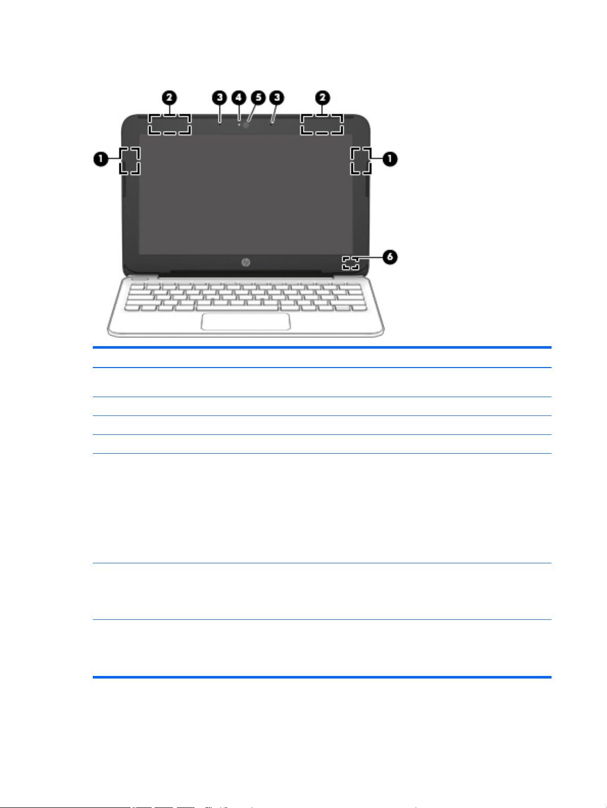
Display
Item Component Description
(1) WLAN antennas* (right WLAN antenna on select
products only)
(2) WWAN antennas* (select products only) Send and receive wireless signals to communicate with WWANs.
(3) Internal microphones Record sound.
(4) Webcam light On: The webcam is in use.
(5) Webcam
‒ or –
3D camera (select products only)
(6) Internal display switch Turns off the display and initiates Sleep if the display is closed
*The antennas are not visible from the outside of the computer. For optimal transmission, keep the areas immediately around
the antennas free from obstructions.
For wireless regulatory notices, see the section of the Regulatory, Safety, and Environmental Notices that applies to your country
or region.
Send and receive wireless signals to communicate with WLANs.
Records video and captures photographs. Some models allow
you to video conference and chat online using streaming video.
To use the webcam:
▲
Type camera in the taskbar search box, and then
select Camera.
To use the 3D camera:
▲
See the computer User’s Guide.
while the power is on.
NOTE: The internal display switch is not visible from
the outside of the computer.
6 Chapter 2 Getting to know your computer
Page 15

Buttons
Item Component Description
(1) Power button
●
When the computer is off, press the button to turn on
the computer.
●
When the computer is on, press the button briefly to
initiate Sleep.
●
When the computer is in the Sleep state, press the button
briefly to exit Sleep.
●
When the computer is in Hibernation, press the button
briefly to exit Hibernation.
CAUTION: Pressing and holding down the power button results
in the loss of unsaved information.
If the computer has stopped responding and shutdown
procedures are ineffective, press and hold the power button
down for at least 5 seconds to turn off the computer.
To learn more about your power settings, see your
power options.
▲
Type power in the taskbar search box, and then select
Power and sleep settings.
‒ or –
Right-click the Start button, and then select
Power Options.
Buttons 7
Page 16

Keys
Item Component Description
(1) esc key Displays system information when pressed in combination with
the fn key.
(2) fn key Executes frequently used system functions when pressed in
combination with the esc key, action keys, or the spacebar.
(3) Windows key Opens the Start menu.
NOTE: Pressing the Windows key again will close
the Start menu.
(4) Action keys Execute frequently used system functions.
8 Chapter 2 Getting to know your computer
Page 17
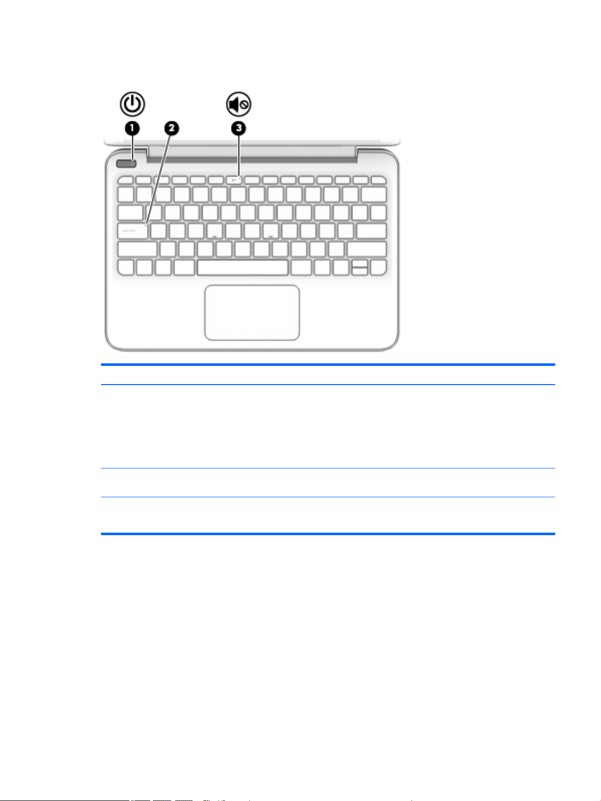
Lights
Item Component Description
(1) Power light
(2) Caps lock light On: Caps lock is on, which switches the key input to all
(3) Mute light
●
On: The computer is on.
●
Blinking: The computer is in the Sleep state, a powersaving state. The computer shuts off power to the display
and other unneeded components.
●
Off: The computer is off or in Hibernation. Hibernation is a
power-saving state that uses the least amount of power.
capital letters.
●
Amber: Computer sound is off.
●
Off: Computer sound is on.
Lights 9
Page 18
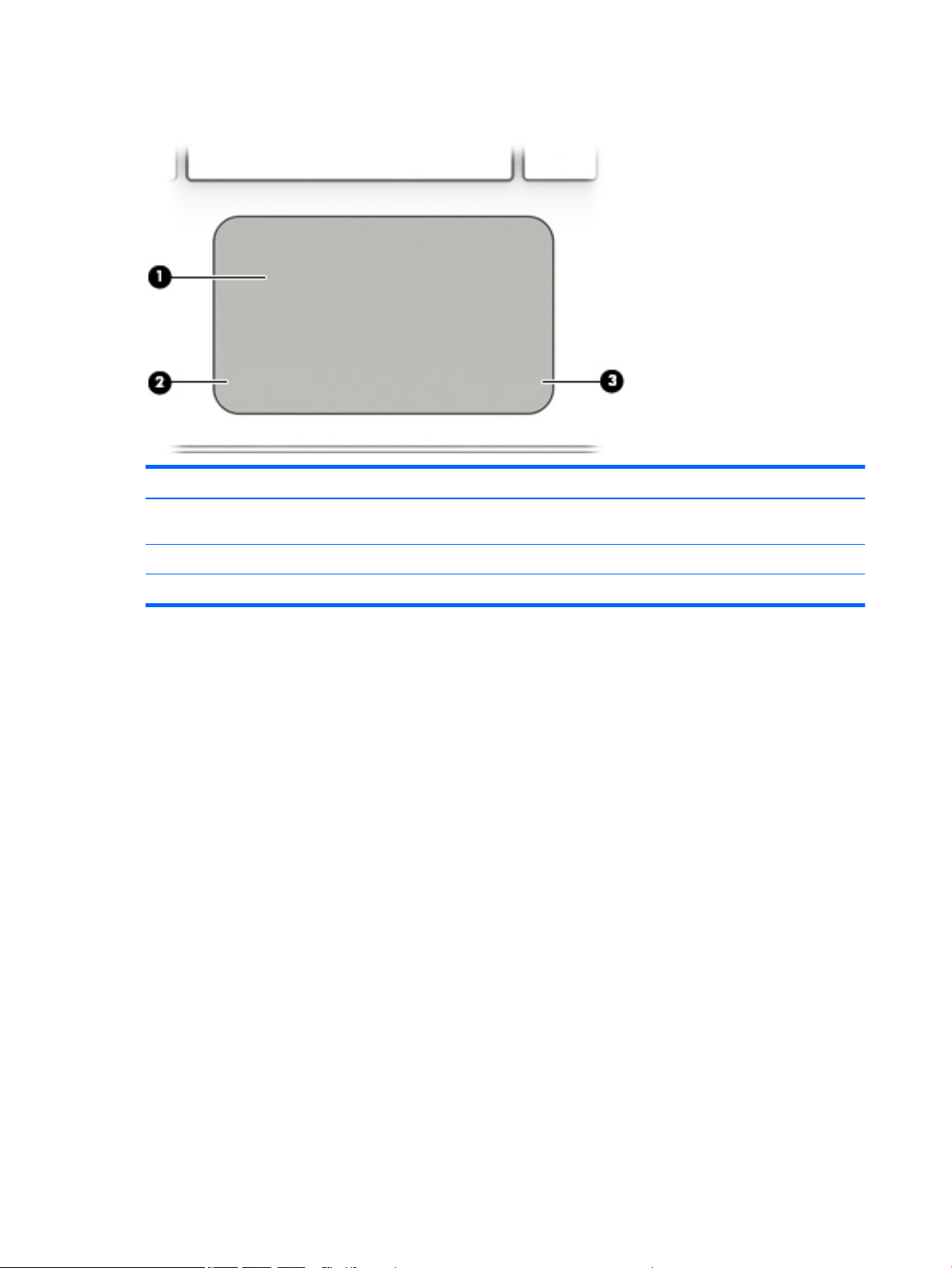
TouchPad
Item Component Description
(1) TouchPad zone Reads your finger gestures to move the pointer or activate items
(2) Left TouchPad button Functions like the left button on an external mouse.
on the screen.
(3) Right TouchPad button Functions like the right button on an external mouse.
10 Chapter 2 Getting to know your computer
Page 19

Left side
Item Component Description
(1) Security cable slot Attaches an optional security cable to the computer.
(2) SIM card slot (select products only) Supports a wireless SIM card.
(3) USB 2.0 port Connects an optional USB device, such as a keyboard, mouse,
(4) Audio-out (headphone)/audio-in (microphone) combo jack Connects optional powered stereo speakers, headphones,
NOTE: The security cable is designed to act as a deterrent,
but it may not prevent the computer from being mishandled
or stolen.
external drive, printer, scanner or USB hub.
earbuds, a headset, or a television audio cable. Also connects an
optional headset microphone. This jack does not support
optional microphone-only devices.
WARNING! To reduce the risk of personal injury, adjust
the volume before putting on headphones, earbuds, or a
headset. For additional safety information, refer to
the Regulatory, Safety, and Environmental Notices.
NOTE: When a device is connected to the jack, the computer
speakers are disabled.
(5) Power light
●
On: The computer is on.
●
Blinking: The computer is in the Sleep state, a powersaving state. The computer shuts off power to the display
and other unneeded components.
●
Off: The computer is off or in Hibernation. Hibernation is a
power-saving state that uses the least amount of power.
Left side 11
Page 20

Right side
Item Component Description
(1) HDMI port Connects an optional video or audio device, such as a high-
(2) USB 3.0 port Connects an optional USB device, such as a keyboard, mouse,
(3) Memory card reader Reads optional memory cards that enable you to store, manage,
definition television, any compatible digital or audio component,
or a high-speed HDMI device.
external drive, printer, scanner or USB hub.
share, or access information.
To insert a card:
1. Hold the card label-side up, with connectors facing
the computer.
2. Insert the card into the memory card reader, and then
press in on the card until it is firmly seated.
To remove a card:
▲
Press in on the card, and then remove it from the memory
card reader.
(4) AC adapter/battery light
(5) Power connector Connects an AC adapter.
●
White: The AC adapter is connected and the battery is
fully charged.
●
Blinking white: The AC adapter is disconnected and
the battery has reached a low battery level.
●
Amber: The AC adapter is connected and the battery
is charging.
●
Off: The battery is not charging.
12 Chapter 2 Getting to know your computer
Page 21
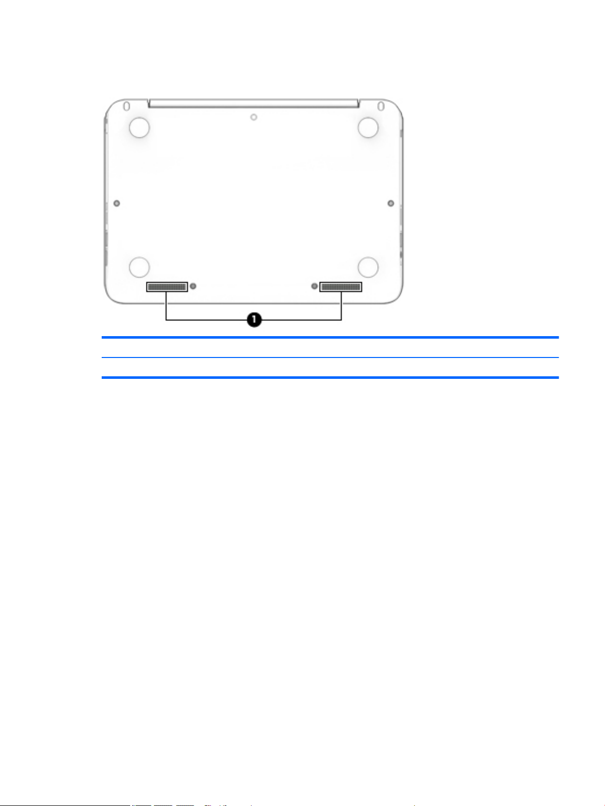
Bottom
Item Component Description
(1) Speakers (2) Produce sound.
Bottom 13
Page 22
3 Illustrated parts catalog
NOTE: HP continually improves and changes product parts. For complete and current information on
supported parts for your computer, go to http://partsurfer.hp.com, select your country or region, and then
follow the on-screen instructions.
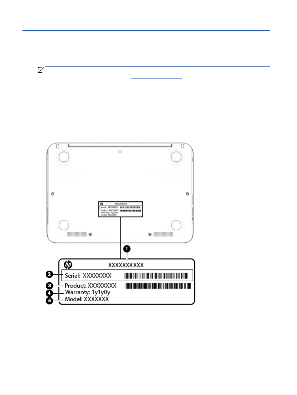
Locating the serial number, model number, product number, and warranty information
The product name (1), serial number (2), product number (3), warranty information (4), and
model number (5), are located on the bottom of the computer. This information may be needed when
travelling internationally or when contacting support.
14 Chapter 3 Illustrated parts catalog
Page 23
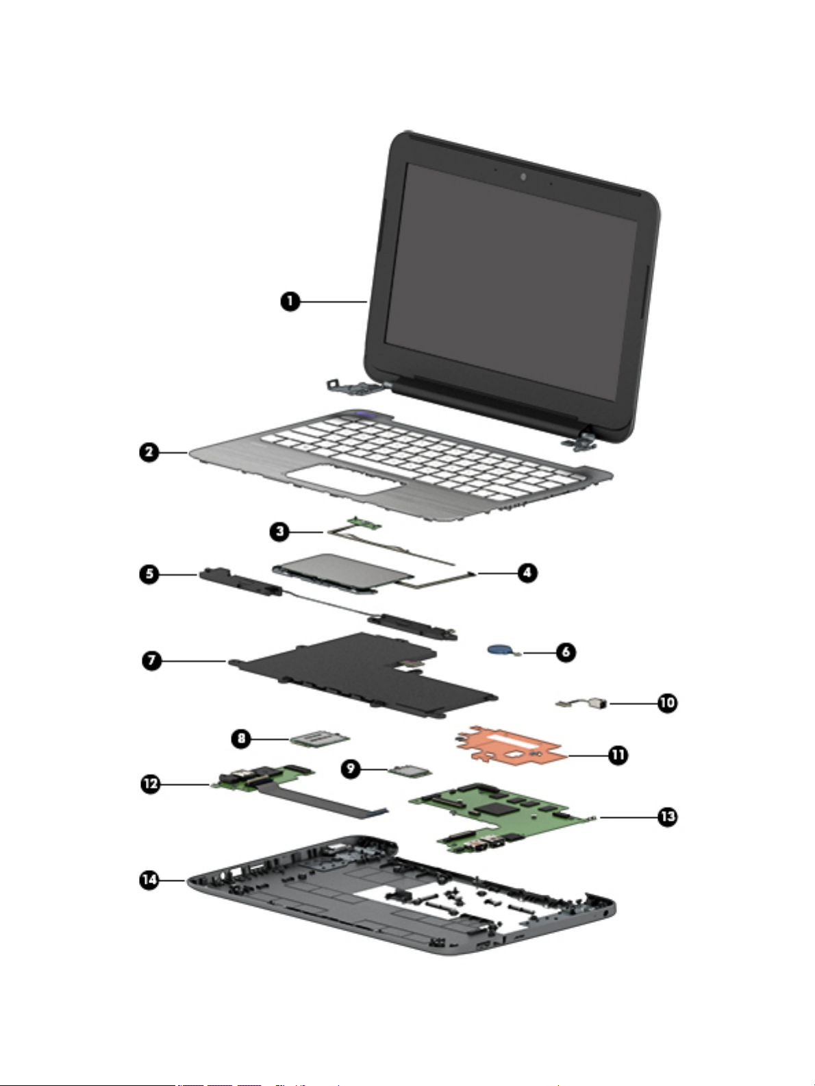
Computer major components
Computer major components 15
Page 24

Item Component Spare part number
(1) Display assembly: The display assembly is spared at the subcomponent level only. For more display assembly spare part
information, see Display assembly subcomponents on page 21.
(2) Keyboard/top cover (includes keyboard cable):
In ash silver finish with black keys for use only on HP Stream 11 Pro G2 Notebook PC computer models:
For use in Canada 832490-DB1
For use in Japan 832490-291
For use in the United States 832490-001
Keyboard/top cover (includes keyboard cable):
In cobalt blue finish with white keys for use only on HP Stream Notebook PC computer models:
For use in Belgium 830788-A41
For use in Bulgaria 830788-261
For use in Canada 830788-DB1
For use in the Czech Republic and Slovenia 830788-FL1
For use in Denmark, Finland, and Norway 830788-DH1
For use in France 830788-051
For use in Germany 830788-041
For use in Greece 830788-151
For use in Hungary 830788-211
For use in Israel 830788-BB1
For use in Italy 830788-061
For use in Japan 830788-291
For use in Latin America 830788-161
For use in the Netherlands 830788-B31
For use in Portugal 830788-131
For use in Romania 830788-271
For use in Russia 830788-251
For use in Saudi Arabia 830788-171
For use in Slovenia 830788-BA1
For use in South Korea 830788-AD1
For use in Spain 830788-071
For use in Switzerland 830788-BG1
For use in Taiwan 830788-AB1
For use in Thailand 830788-281
For use in Turkey 830788-141
16 Chapter 3 Illustrated parts catalog
Page 25

Item Component Spare part number
For use in the United Kingdom 830788-031
For use in the United States 830788-001
Keyboard/top cover (includes keyboard cable):
In violet purple blue finish with white keys for use only on HP Stream Notebook PC computer models:
For use in Belgium 830802-A41
For use in Bulgaria 830802-261
For use in Canada 830802-DB1
For use in the Czech Republic and Slovenia 830802-FL1
For use in Denmark, Finland, and Norway 830802-DH1
For use in France 830802-051
For use in Germany 830802-041
For use in Greece 830802-151
For use in Hungary 830802-211
For use in Israel 830802-BB1
For use in Italy 830802-061
For use in Japan 830802-291
For use in Latin America 830802-161
For use in the Netherlands 830802-B31
For use in Portugal 830802-131
For use in Romania 830802-271
For use in Russia 830802-251
For use in Saudi Arabia 830802-171
For use in Slovenia 830802-BA1
For use in South Korea 830802-AD1
For use in Spain 830802-071
For use in Switzerland 830802-BG1
For use in Taiwan 830802-AB1
For use in Thailand 830802-281
For use in Turkey 830802-141
For use in the United Kingdom 830802-031
For use in the United States 830802-001
(3) Power button board
NOTE: The power button board spare part kit does not include the power button board
cable. The power button board cable is available using spare part number 830757-001.
(4) TouchPad board (includes double-sided adhesive):
830756-001
Computer major components 17
Page 26

Item Component Spare part number
NOTE: The TouchPad board spare part kit does not include the TouchPad board cable. The TouchPad board cable is
available using spare part number 830763-001.
In ash silver finish for use only on HP Stream 11 Pro G2 Notebook PC computer models 835665-001
In cobalt blue finish for use only on HP Stream Notebook PC computer models 830762-001
In violet purple finish for use only on HP Stream Notebook PC computer models 835663-001
(5) Speakers (include left and right speakers and cables) 830761-001
(6) RTC battery (includes cable and double-sided adhesive) 830764-001
(7) Battery (2-cell, 37-WHr, 4.96-AHr, Li-ion; includes cable):
For use only on HP Stream 11 Pro G2 Notebook PC computer models 824536-850
For use only on HP Stream Notebook PC computer models 824560-005
(8) WLAN module:
Intel Dual Band Wireless-AC 7265 802.11 ac 2×2 WiFi + Bluetooth 4.0 Combo Adapter for
use only on HP Stream 11 Pro G2 Notebook PC computer models
For use only on HP Stream Notebook PC computer models:
Broadcom BCM43142 802.11b/g/n 1×1 Wi-Fi + Bluetooth 4.0 M.2 Combo Adapter 803344-001
Intel 3165NGWG 1 ac 1×1 + Bluetooth 4.0 LE PCIe+USB NGFF 2230 806723-005
Realtek RTL8723BE 802.11b/g/n 1×1 Wi-Fi + Bluetooth 4.0 Combo Adapter 792204-001
Realtek RTL8723BE 802.11bgn Wi-Fi Adapter 792610-005
(9) WWAN module (for use only on HP Stream Notebook PC computer models):
HP lt4110 LTE/HSPA+ 4G Module 750098-001
HP lt4110 LTE/HSPA+ 4G Module 756993-005
(10) Power connector cable 743480-002
(11) Heat sink (includes replacement thermal material) 830781-001
(12) Connector board (includes audio jack and USB port):
NOTE: The connector board spare part kit does not include the connector board cable. The connector board cable is
available using spare part number 830759-001.
For use only on HP Stream Notebook PC computer models equipped with WWAN capability
(includes SIM slot and WWAN slot)
For use only on computer models not equipped with WWAN capability 830801-001
756055-011
830758-001
(13) System board (includes HDMI port, micro-SD card reader slot, USB port, WLAN slot, and replacement thermal material):
For use only on HP Stream Notebook PC computer models:
Equipped with an Intel Celeron N3150 1.60-GHz (SC turbo up to 2.08-GHz) quad core
processor (1600-MHz FSB, 2.0-MB L2 cache, 4.0 W), 4.0-GB of system memory, 64-GB of
eMMC system storage, and the Windows 10 Professional operating system
Equipped with an Intel Celeron N3150 1.60-GHz (SC turbo up to 2.08-GHz) quad core
processor (1600-MHz FSB, 2.0-MB L2 cache, 4.0 W), 4.0-GB of system memory, 64-GB of
eMMC system storage, and a non-Windows operating system
18 Chapter 3 Illustrated parts catalog
830813-601
830813-001
Page 27

Item Component Spare part number
Equipped with an Intel Celeron N3150 1.60-GHz (SC turbo up to 2.08-GHz) quad core
processor (1600-MHz FSB, 2.0-MB L2 cache, 4.0 W), 2.0-GB of system memory, 64-GB of
eMMC system storage, and the Windows 10 Professional operating system
Equipped with an Intel Celeron N3150 1.60-GHz (SC turbo up to 2.08-GHz) quad core
processor (1600-MHz FSB, 2.0-MB L2 cache, 4.0 W), 2.0-GB of system memory, 64-GB of
eMMC system storage, and a non-Windows operating system
Equipped with an Intel Celeron N3150 1.60-GHz (SC turbo up to 2.08-GHz) quad core
processor (1600-MHz FSB, 2.0-MB L2 cache, 4.0 W), 2.0-GB of system memory, 32-GB of
eMMC system storage, and the Windows 10 Professional operating system
Equipped with an Intel Celeron N3150 1.60-GHz (SC turbo up to 2.08-GHz) quad core
processor (1600-MHz FSB, 2.0-MB L2 cache, 4.0 W), 2.0-GB of system memory, 32-GB of
eMMC system storage, and a non-Windows operating system
Equipped with an Intel Celeron N3050 1.60-GHz (SC turbo up to 2.16-GHz) dual core
processor (1600-MHz FSB, 2.0-MB L2 cache, 4.0 W), 4.0-GB of system memory, 64-GB of
eMMC system storage, and the Windows 10 Professional operating system
Equipped with an Intel Celeron N3050 1.60-GHz (SC turbo up to 2.16-GHz) dual core
processor (1600-MHz FSB, 2.0-MB L2 cache, 4.0 W), 4.0-GB of system memory, 64-GB of
eMMC system storage, and a non-Windows operating system
Equipped with an Intel Celeron N3050 1.60-GHz (SC turbo up to 2.16-GHz) dual core
processor (1600-MHz FSB, 2.0-MB L2 cache, 4.0 W), 2.0-GB of system memory, 64-GB of
eMMC system storage, and the Windows 10 Professional operating system
Equipped with an Intel Celeron N3050 1.60-GHz (SC turbo up to 2.16-GHz) dual core
processor (1600-MHz FSB, 2.0-MB L2 cache, 4.0 W), 2.0-GB of system memory, 64-GB of
eMMC system storage, and a non-Windows operating system
830812-601
830812-001
830811-601
830811-001
830816-601
830816-001
830815-601
830815-001
Equipped with an Intel Celeron N3050 1.60-GHz (SC turbo up to 2.16-GHz) dual core
processor (1600-MHz FSB, 2.0-MB L2 cache, 4.0 W), 2.0-GB of system memory, 32-GB of
eMMC system storage, and the Windows 10 Professional operating system
Equipped with an Intel Celeron N3050 1.60-GHz (SC turbo up to 2.16-GHz) dual core
processor (1600-MHz FSB, 2.0-MB L2 cache, 4.0 W), 2.0-GB of system memory, 32-GB of
eMMC system storage, and a non-Windows operating system
Equipped with an Intel Celeron N2840 2.16-GHz (SC turbo up to 2.58-GHz) dual core
processor (1333-MHz FSB, 1.0-GB L2 cache, 4.5 W), 4.0-GB of system memory, 32-GB of
eMMC system storage, and the Windows 10 Professional operating system
Equipped with an Intel Celeron N2840 2.16-GHz (SC turbo up to 2.58-GHz) dual core
processor (1333-MHz FSB, 1.0-GB L2 cache, 4.5 W), 2.0-GB of system memory, 32-GB of
eMMC system storage, and a non-Windows operating system
For use only on HP Stream 11 Pro G2 Notebook PC computer models:
Equipped with an Intel Celeron N3050 1.60-GHz (SC turbo up to 2.16-GHz) dual core
processor (1600-MHz FSB, 2.0-MB L2 cache, 4.0 W), 4.0-GB of system memory, 64-GB of
eMMC system storage, and the Windows 10 Professional operating system
Equipped with an Intel Celeron N3050 1.60-GHz (SC turbo up to 2.16-GHz) dual core
processor (1600-MHz FSB, 2.0-MB L2 cache, 4.0 W), 4.0-GB of system memory, 64-GB of
eMMC system storage, and a non-Windows operating system
Equipped with an Intel Celeron N3050 1.60-GHz (SC turbo up to 2.16-GHz) dual core
processor (1600-MHz FSB, 2.0-MB L2 cache, 4.0 W), 2.0-GB of system memory, 64-GB of
eMMC system storage, and the Windows 10 Professional operating system
Equipped with an Intel Celeron N3050 1.60-GHz (SC turbo up to 2.16-GHz) dual core
processor (1600-MHz FSB, 2.0-MB L2 cache, 4.0 W), 2.0-GB of system memory, 64-GB of
eMMC system storage, and a non-Windows operating system
830814-601
830814-001
830817-601
830817-001
832527-601
832527-001
832526-601
832526-001
Computer major components 19
Page 28

Item Component Spare part number
Equipped with an Intel Celeron N3050 1.60-GHz (SC turbo up to 2.16-GHz) dual core
processor (1600-MHz FSB, 2.0-MB L2 cache, 4.0 W), 2.0-GB of system memory, 32-GB of
eMMC system storage, and the Windows 10 Professional operating system
Equipped with an Intel Celeron N3050 1.60-GHz (SC turbo up to 2.16-GHz) dual core
processor (1600-MHz FSB, 2.0-MB L2 cache, 4.0 W), 2.0-GB of system memory, 32-GB of
eMMC system storage, and a non-Windows operating system
(14) Base enclosure:
In ash silver finish for use only on HP Stream 11 Pro G2 Notebook PC computer models 832494-001
For use only on HP Stream Notebook PC computer models:
In cobalt blue finish:
For use only on computer models equipped with WWAN capability 830782-001
For only use on computer models not equipped with WWAN capability 830779-001
In violet purple finish:
For use only on computer models equipped with WWAN capability 830783-001
For only use on computer models not equipped with WWAN capability 830780-001
Rubber Kit (not illustrated, includes 2 display bezel screw covers, 4 computer feet, and 2 bottom cover screw covers):
In ash silver finish for use only on HP Stream 11 Pro G2 Notebook PC computer models 832491-001
In cobalt blue finish for use only on HP Stream Notebook PC computer models 830768-001
832525-601
832525-001
In violet purple finish for use only on HP Stream Notebook PC computer models 830807-001
20 Chapter 3 Illustrated parts catalog
Page 29

Display assembly subcomponents
Item Component Spare part number
(1) Display bezel screw covers – available in the Rubber Kits and included in all display component spare part kits:
Rubber Kit in ash silver finish for use only on HP Stream 11 Pro G2 Notebook PC
computer models
Rubber Kit in cobalt blue finish for use only on HP Stream Notebook PC computer models 830768-001
Rubber Kit in violet purple finish for use only on HP Stream Notebook PC computer models 830807-001
(2) Display bezel:
In ash silver finish for use only on HP Stream 11 Pro G2 Notebook PC computer models 832493-001
830768-001
Display assembly subcomponents 21
Page 30

Item Component Spare part number
In cobalt blue finish for use only on HP Stream Notebook PC computer models 830771-001
In violet purple finish for use only on HP Stream Notebook PC computer models 830785-001
(3) Webcam/microphone module (includes double-sided adhesive)
For use only on HP Stream 11 Pro G2 Notebook PC computer models 832675-001
For use only on HP Stream Notebook PC computer models 833620-001
(4) Display panel:
11.6-in, HD, AntiGlare, (1366×768), SVA, LED, flat (3.3.6-mm) display panel for use only on
HP Stream 11 Pro G2 Notebook PC computer models
11.6-in, HD, AntiGlare, (1366×768), SVA, LED, slim (3.0-mm) display panel for use only on
HP Stream Notebook PC computer models
11.6-in, HD, (1366×768), SVA, WLED, flat (3.6-mm) display panel for use only on HP Stream
Notebook PC computer models
(5) Display Hinge Kit (includes left and right display hinges)
For use only on HP Stream 11 Pro G2 Notebook PC computer models 832570-001
For use only on HP Stream Notebook PC computer models 730770-001
(6) Display panel cable (includes webcam/microphone module cable)
For use only on HP Stream 11 Pro G2 Notebook PC computer models 832755-001
For use only on HP Stream Notebook PC computer models 830772-001
(7) WWAN antenna (for use only on HP Stream Notebook PC computer models, includes left
and right WWAN cables and transceivers)
(8) WLAN antenna (includes left and right WLAN cables and transceivers)
For use only on HP Stream 11 Pro G2 Notebook PC computer models 832568-001
For use only on HP Stream Notebook PC computer models 830774-001
(9) Display enclosure (includes rubber padding and shielding):
832674-001
762229-001
834445-001
830775-001
In ash silver finish for use only on HP Stream 11 Pro G2 Notebook PC computer models 832492-001
In cobalt blue finish for use only on HP Stream Notebook PC computer models 830773-001
In violet purple finish for use only on HP Stream Notebook PC computer models 830786-001
Miscellaneous parts
Component
AC adapter:
65-W HP Smart AC adapter (non-PFC, EM, 4.5-mm) for use on all computer models 741553-850
65-W HP Smart AC adapter (non-PFC, EM, 4.5-mm) for use only on HP Stream 11 Pro G2 Notebook PC
computer models
45-W HP Smart AC adapter (non-PFC, RC, 4.5-mm) for use only on HP Stream Notebook PC
computer models
22 Chapter 3 Illustrated parts catalog
Spare part number
693667-800
714635-850
Page 31

Component Spare part number
HP 65-W 3-pin-to-standard-connector cable 414135-001
HP business backpack 718548-001
HP essential top load case 679921-001
HP HDMI-to-DVI-D connector adapter 691227-001
HP HDMI-to-VGA adapter 701943-001
HP professional slim top load case 703888-001
HP Smart AC adapter dongle (7.4-mm) 734734-001
HP ultraslim keyed cable lock 703372-001
HP USB external DVD-RW Drive 747080-001
HP USB 3.0 port replicator 690650-001
HP USB 3.0A-to-USB 3.0B cable (0.5-M) 690652-001
HP USB travel mouse 757770-001
Power cord for use only on HP Stream Notebook PC computer models (3-pin, black, 1.00-meter):
For use in Australia 755530-011
For use in Denmark 755530-081
For use in Europe 755530-021
For use in India 755530-D61
For use in Israel 755530-BB1
For use in Italy 755530-061
For use in Japan 755530-291
For use in North America 755530-001
For use in the People’s Republic of China 755530-AA1
For use in South Africa 755530-AR1
For use in South Korea 755530-AD1
For use in Switzerland 755530-111
For use in Taiwan 755530-AB1
For use in Thailand 755530-281
For use in the United Kingdom and Singapore 755530-031
Power cord for use only on HP Stream Notebook PC computer models (C5, 1.00-meter):
For use in Australia 213356-008
For use in Denmark 213353-008
For use in Europe 213350-009
For use in India 404827-003
For use in Israel 398063-003
Miscellaneous parts 23
Page 32

Component Spare part number
For use in Italy 213352-008
For use in Japan 349756-003
For use in North America 213349-009
For use in the People’s Republic of China 286497-008
For use in South Korea 267836-008
For use in Switzerland 213354-008
For use in Taiwan 393313-003
For use in Thailand 285096-006
For use in the United Kingdom and Singapore 213351-008
Power cord (Option 917, 3-cord, 1.00-meter, ROHS) 361240-002
Power cord for use only on HP Stream 11 Pro G2 Notebook PC computer models (C5, 1.00-meter):
For use in Australia 213356-001
For use in Europe 213350-001
For use in Japan 349756-001
For use in North America 213349-001
For use in the United Kingdom and Singapore 213351-001
Rubber Kit (includes 2 display bezel screw covers, 4 rubber feet, and 2 rubber screw covers):
In ash silver finish for use only on HP Stream 11 Pro G2 Notebook PC computer models 832492-001
In cobalt blue finish for use only on HP Stream Notebook PC computer models 830773-001
In violet purple finish for use only on HP Stream Notebook PC computer models 830786-001
Screw Kit:
For use only on HP Stream 11 Pro G2 Notebook PC computer models 830769-001
For use only on HP Stream Notebook PC computer models 822634-001
24 Chapter 3 Illustrated parts catalog
Page 33

4 Removal and replacement preliminary
requirements
Tools required
You will need the following tools to complete the removal and replacement procedures:
●
Flat-bladed screw driver
●
Magnetic screw driver
●
Phillips P0 screw driver
Service considerations
The following sections include some of the considerations that you must keep in mind during disassembly
and assembly procedures.
NOTE: As you remove each subassembly from the computer, place the subassembly (and all accompanying
screws) away from the work area to prevent damage.
Plastic parts
CAUTION: Using excessive force during disassembly and reassembly can damage plastic parts. Use care
when handling the plastic parts. Apply pressure only at the points designated in
the maintenance instructions.
Cables and connectors
CAUTION: When servicing the computer, be sure that cables are placed in their proper locations during
the reassembly process. Improper cable placement can damage the computer.
Cables must be handled with extreme care to avoid damage. Apply only the tension required to unseat or
seat the cables during removal and insertion. Handle cables by the connector whenever possible. In all cases,
avoid bending, twisting, or tearing cables. Be sure that cables are routed in such a way that they cannot be
caught or snagged by parts being removed or replaced. Handle flex cables with extreme care; these cables
tear easily.
Tools required 25
Page 34

Drive handling
CAUTION: Drives are fragile components that must be handled with care. To prevent damage to
the computer, damage to a drive, or loss of information, observe these precautions:
Before removing or inserting a drive, shut down the computer. If you are unsure whether the computer is off
or in Hibernation, turn the computer on, and then shut it down through the operating system.
Before handling a drive, be sure that you are discharged of static electricity. While handling a drive, avoid
touching the connector.
Before removing a diskette drive or optical drive, be sure that a diskette or disc is not in the drive and be sure
that the optical drive tray is closed.
Handle drives on surfaces covered with at least one inch of shock-proof foam.
Avoid dropping drives from any height onto any surface.
After removing drive, place it in a static-proof bag.
Avoid exposing a drive to products that have magnetic fields, such as monitors or speakers.
Avoid exposing a drive to temperature extremes or liquids.
If a drive must be mailed, place the drive in a bubble pack mailer or other suitable form of protective
packaging and label the package “FRAGILE.”
26 Chapter 4 Removal and replacement preliminary requirements
Page 35

Grounding guidelines
Electrostatic discharge damage
Electronic components are sensitive to electrostatic discharge (ESD). Circuitry design and structure
determine the degree of sensitivity. Networks built into many integrated circuits provide some protection,
but in many cases, ESD contains enough power to alter device parameters or melt silicon junctions.
A discharge of static electricity from a finger or other conductor can destroy static-sensitive devices or
microcircuitry. Even if the spark is neither felt nor heard, damage may have occurred.
An electronic device exposed to ESD may not be affected at all and can work perfectly throughout a normal
cycle. Or the device may function normally for a while, then degrade in the internal layers, reducing its
life expectancy.
CAUTION: To prevent damage to the computer when you are removing or installing internal components,
observe these precautions:
Keep components in their electrostatic-safe containers until you are ready to install them.
Before touching an electronic component, discharge static electricity by using the guidelines described in
this section.
Avoid touching pins, leads, and circuitry. Handle electronic components as little as possible.
If you remove a component, place it in an electrostatic-safe container.
The following table shows how humidity affects the electrostatic voltage levels generated by
different activities.
CAUTION: A product can be degraded by as little as 700 V.
Typical electrostatic voltage levels
Relative humidity
Event 10% 40% 55%
Walking across carpet 35,000 V 15,000 V 7,500 V
Walking across vinyl floor 12,000 V 5,000 V 3,000 V
Motions of bench worker 6,000 V 800 V 400 V
Removing DIPS from plastic tube 2,000 V 700 V 400 V
Removing DIPS from vinyl tray 11,500 V 4,000 V 2,000 V
Removing DIPS from Styrofoam 14,500 V 5,000 V 3,500 V
Removing bubble pack from PCB 26,500 V 20,000 V 7,000 V
Packing PCBs in foam-lined box 21,000 V 11,000 V 5,000 V
Grounding guidelines 27
Page 36

Packaging and transporting guidelines
Follow these grounding guidelines when packaging and transporting equipment:
●
To avoid hand contact, transport products in static-safe tubes, bags, or boxes.
●
Protect ESD-sensitive parts and assemblies with conductive or approved containers or packaging.
●
Keep ESD-sensitive parts in their containers until the parts arrive at static-free workstations.
●
Place items on a grounded surface before removing items from their containers.
●
Always be properly grounded when touching a component or assembly.
●
Store reusable ESD-sensitive parts from assemblies in protective packaging or nonconductive foam.
●
Use transporters and conveyors made of antistatic belts and roller bushings. Be sure that mechanized
equipment used for moving materials is wired to ground and that proper materials are selected to avoid
static charging. When grounding is not possible, use an ionizer to dissipate electric charges.
Workstation guidelines
Follow these grounding workstation guidelines:
●
Cover the workstation with approved static-shielding material.
●
Use a wrist strap connected to a properly grounded work surface and use properly grounded tools
and equipment.
●
Use conductive field service tools, such as cutters, screw drivers, and vacuums.
●
When fixtures must directly contact dissipative surfaces, use fixtures made only of staticsafe materials.
●
Keep the work area free of nonconductive materials, such as ordinary plastic assembly aids
and Styrofoam.
●
Handle ESD-sensitive components, parts, and assemblies by the case or PCM laminate. Handle these
items only at static-free workstations.
●
Avoid contact with pins, leads, or circuitry.
●
Turn off power and input signals before inserting or removing connectors or test equipment.
28 Chapter 4 Removal and replacement preliminary requirements
Page 37

Equipment guidelines
Grounding equipment must include either a wrist strap or a foot strap at a grounded workstation.
●
When seated, wear a wrist strap connected to a grounded system. Wrist straps are flexible straps with a
minimum of one megohm ±10% resistance in the ground cords. To provide proper ground, wear a strap
snugly against the skin at all times. On grounded mats with banana-plug connectors, use alligator clips
to connect a wrist strap.
●
When standing, use foot straps and a grounded floor mat. Foot straps (heel, toe, or boot straps) can be
used at standing workstations and are compatible with most types of shoes or boots. On conductive
floors or dissipative floor mats, use foot straps on both feet with a minimum of one megohm resistance
between the operator and ground. To be effective, the conductive must be worn in contact with
the skin.
The following grounding equipment is recommended to prevent electrostatic damage:
●
Antistatic tape
●
Antistatic smocks, aprons, and sleeve protectors
●
Conductive bins and other assembly or soldering aids
●
Nonconductive foam
●
Conductive computerop workstations with ground cords of one megohm resistance
●
Static-dissipative tables or floor mats with hard ties to the ground
●
Field service kits
●
Static awareness labels
●
Material-handling packages
●
Nonconductive plastic bags, tubes, or boxes
●
Metal tote boxes
●
Electrostatic voltage levels and protective materials
The following table lists the shielding protection provided by antistatic bags and floor mats.
Material Use Voltage protection level
Antistatic plastics Bags 1,500 V
Carbon-loaded plastic Floor mats 7,500 V
Metallized laminate Floor mats 5,000 V
Grounding guidelines 29
Page 38

5 Removal and replacement procedures
CAUTION: Components described in this chapter should only be accessed by an authorized service provider.
Accessing these parts can damage the computer or void the warranty.
NOTE: HP continually improves and changes product parts. For complete and current information on
supported parts for your computer, go to http://partsurfer.hp.com, select your country or region, and then
follow the on-screen instructions.
Component replacement procedures
There are as many as 54 screws that must be removed, replaced, and/or loosened when servicing
the computer. Make special note of each screw size and location during removal and replacement.
Keyboard/top cover
Description Spare part number Description Spare part number
In ash silver finish with black keys for use only on HP Stream 11
Pro G2 Notebook PC computer models:
For use in Canada 832490-DB1 For use in the United States 832490-001
In cobalt blue finish with white keys for use only on HP Stream
Notebook PC computer models:
For use in Belgium 830788-A41 For use in Portugal 830788-131
For use in Bulgaria 830788-261 For use in Romania 830788-271
For use in Canada 830788-DB1 For use in Russia 830788-251
For use in the Czech Republic
and Slovenia
For use in Denmark, Finland,
and Norway
For use in France 830788-051 For use in South Korea 830788-AD1
For use in Germany 830788-041 For use in Spain 830788-071
For use in Greece 830788-151 For use in Switzerland 830788-BG1
For use in Hungary 830788-211 For use in Taiwan 830788-AB1
For use in Israel 830788-BB1 For use in Thailand 830788-281
For use in Italy 830788-061 For use in Turkey 830788-141
830788-FL1 For use in Saudi Arabia 830788-171
830788-DH1 For use in Slovenia 830788-BA1
For use in Japan 832490-291
For use in the Netherlands 830788-B31
For use in Japan 830788-291 For use in the United Kingdom 830788-031
For use in Latin America 830788-161 For use in the United States 830788-001
In violet purple blue finish with white keys for use only on HP
Stream Notebook PC computer models:
For use in Belgium 830802-A41 For use in Portugal 830802-131
30 Chapter 5 Removal and replacement procedures
For use in the Netherlands 830802-B31
Page 39

Description Spare part number Description Spare part number
For use in Bulgaria 830802-261 For use in Romania 830802-271
For use in Canada 830802-DB1 For use in Russia 830802-251
For use in the Czech Republic
and Slovenia
For use in Denmark, Finland,
and Norway
For use in France 830802-051 For use in South Korea 830802-AD1
For use in Germany 830802-041 For use in Spain 830802-071
For use in Greece 830802-151 For use in Switzerland 830802-BG1
For use in Hungary 830802-211 For use in Taiwan 830802-AB1
For use in Israel 830802-BB1 For use in Thailand 830802-281
For use in Italy 830802-061 For use in Turkey 830802-141
For use in Japan 830802-291 For use in the United Kingdom 830802-031
For use in Latin America 830802-161 For use in the United States 830802-001
830802-FL1 For use in Saudi Arabia 830802-171
830802-DH1 For use in Slovenia 830802-BA1
Before removing the keyboard/top cover, follow these steps:
1. Turn off the computer. If you are unsure whether the computer is off or in Hibernation, turn
the computer on, and then shut it down through the operating system.
2. Disconnect the power from the computer by unplugging the power cord from the computer.
3. Disconnect all external devices from the computer.
NOTE: When replacing the keyboard/top cover, be sure that the TouchPad board (see TouchPad board
on page 35) and power button board (see Power button board on page 36) are removed from
the defective keyboard/top cover and installed on the replacement keyboard/top cover.
Remove the keyboard/top cover:
1. Remove the four computer feet (1).
2. Remove the two screw covers (2).
The computer feet and screw covers are included in the Rubber Kit, using the following spare part
numbers:
●
832491-001 – In ash silver finish for use only on HP Stream 11 Pro G2 Notebook PC
computer models
●
830768-001 – In cobalt blue finish for use only on HP Stream Notebook PC computer models
●
830807-001 – In violet purple finish for use only on HP Stream Notebook PC computer models
Component replacement procedures 31
Page 40

3. Remove the eleven Phillips PM2.0×5.7 screws (3) that secure the keyboard/top cover to
the bottom cover.
4. Turn the computer right side up with the front toward you.
5. Open the computer as far as it will open.
6. Insert a case utility tool (1) or similar thin, plastic tool between the front edge of the keyboard/
top cover and the bottom cover.
7. Lift the front edge (2) of the keyboard/top cover until it separates from the front edge of
the bottom cover.
32 Chapter 5 Removal and replacement procedures
Page 41

8. Disconnect the battery cable from the system board. cad edit-zoom out for more perspective
9. Release the zero insertion force (ZIF) connector (1) to which the power button board cable is attached,
and then disconnect the power button board cable from the system board.
10. Release the ZIF connector (2) to which the keyboard cable is attached, and then disconnect
the keyboard cable from the system board.
11. Release the ZIF connector (3) to which the TouchPad board cable is attached, and then disconnect
the TouchPad board cable from the system board.
Component replacement procedures 33
Page 42

12. Remove the keyboard/top cover (4).
13. Remove the keyboard/top cover.
Reverse this procedure to install the keyboard/top cover.
34 Chapter 5 Removal and replacement procedures
Page 43

TouchPad board
NOTE: The TouchPad board spare part kit does not include the TouchPad board cable. The TouchPad board
cable is available using spare part number 830763-001.
Description Spare part number
In ash silver finish for use only on HP Stream 11 Pro G2 Notebook PC computer models 835665-001
In cobalt blue finish for use only on HP Stream Notebook PC computer models 830762-001
In violet purple finish for use only on HP Stream Notebook PC computer models 835663-001
Before removing the TouchPad board, follow these steps:
1. Turn off the computer. If you are unsure whether the computer is off or in Hibernation, turn
the computer on, and then shut it down through the operating system.
2. Disconnect the power from the computer by unplugging the power cord from the computer.
3. Disconnect all external devices from the computer.
4. Remove the keyboard/top cover (see Keyboard/top cover on page 30).
Remove the TouchPad board:
1. Turn the keyboard/top cover upside down with the front toward you.
2. Remove the four Phillips PM2.0×2.8 screws (1) that secure the TouchPad board bracket
and TouchPad board to the top cover.
3. Remove the three Phillips PM2.0×2.2 broad head screws (2) that secure the TouchPad board to
the top cover.
4. Remove the TouchPad board bracket (3).
Component replacement procedures 35
Page 44

5. Remove the TouchPad board (4) and cable.
Reverse this procedure to install the TouchPad board.
Power button board
NOTE: The power button board spare part kit does not include the power button board cable. The power
button board cable is available using spare part number 830757-001.
Description Spare part number
Power button board 830756-001
Before removing the power button board, follow these steps:
1. Turn off the computer. If you are unsure whether the computer is off or in Hibernation, turn
the computer on, and then shut it down through the operating system.
2. Disconnect the power from the computer by unplugging the power cord from the computer.
3. Disconnect all external devices from the computer.
4. Remove the keyboard/top cover (see Keyboard/top cover on page 30).
Remove the power button board:
1. Turn the keyboard/top cover upside down with the front toward you.
2. Detach the power button board cable (1) from the keyboard/top cover. (The power button board cable
is attached to the keyboard/top cover with double-sided adhesive at two locations.)
3. Remove the two Phillips PM2.0×2.8 screws (2) that secure the power button board to the keyboard/
top cover.
36 Chapter 5 Removal and replacement procedures
Page 45

4. Remove the power button board (3) and cable.
Reverse this procedure to install the power button board.
Speakers
Before removing the speakers, follow these steps:
1. Turn off the computer. If you are unsure whether the computer is off or in Hibernation, turn
2. Disconnect the power from the computer by unplugging the power cord from the computer.
3. Disconnect all external devices from the computer.
4. Remove the keyboard/top cover (see Keyboard/top cover on page 30).
Remove the speakers:
1. Disconnect the speaker cable from the system board (1).
2. Release the speaker cables from the routing clips (2) built into the battery.
3. Remove the two Phillips PM2.0×3.3 screws (3) that secure the speakers to the bottom cover.
Description Spare part number
Speakers (includes left and right speakers and cables) 830761-001
the computer on, and then shut it down through the operating system.
Component replacement procedures 37
Page 46

4. Remove the speakers (4).
Reverse this procedure to install the speakers.
RTC battery
Description Spare part number
RTC battery (includes cable and double-sided adhesive) 830764-001
Before removing the RTC battery, follow these steps:
1. Turn off the computer. If you are unsure whether the computer is off or in Hibernation, turn
2. Disconnect the power from the computer by unplugging the power cord from the computer.
3. Disconnect all external devices from the computer.
4. Remove the keyboard/top cover (see Keyboard/top cover on page 30).
Remove the RTC battery:
1. Disconnect the RTC battery cable (1) from the system board.
the computer on, and then shut it down through the operating system.
38 Chapter 5 Removal and replacement procedures
Page 47

2. Detach the RTC battery (2) from the battery. (The RTC battery is attached to the battery with double-
sided adhesive.) cad edit-visible line on bottom border
Battery
3. Remove the RTC battery and cable.
Reverse this procedure to install the RTC battery.
Description Spare part number
For use only on HP Stream 11 Pro G2 Notebook PC computer models 824536-850
For use only on HP Stream Notebook PC computer models 824560-005
Before removing the battery, follow these steps:
1. Turn off the computer. If you are unsure whether the computer is off or in Hibernation, turn
the computer on, and then shut it down through the operating system.
2. Disconnect the power from the computer by unplugging the power cord from the computer.
3. Disconnect all external devices from the computer.
4. Remove the keyboard/top cover (see Keyboard/top cover on page 30).
NOTE: When replacing the battery, be sure that the RTC battery (see RTC battery on page 38) is removed
from the defective battery and installed on the replacement battery.
Remove the battery:
1. Disconnect the battery cable (1) from the system board.
2. Release the speaker cables from the routing clips (2) built into the battery.
3. Disconnect the RTC battery cable (3) from the system board.
Component replacement procedures 39
Page 48

4. Remove the six Phillips PM2.0×3.3 screws (4) that secure the battery to the bottom cover.
5. Slide the battery (5) up and back.
6. Remove the battery (6).
Reverse this procedure to install the battery.
40 Chapter 5 Removal and replacement procedures
Page 49

WLAN module
Description Spare part number
Intel Dual Band Wireless-AC 7265 802.11 ac 2×2 WiFi + Bluetooth 4.0 Combo Adapter for use only on
HP Stream 11 Pro G2 Notebook PC computer models
For use only on HP Stream Notebook PC computer models:
Broadcom BCM43142 802.11b/g/n 1×1 Wi-Fi + Bluetooth 4.0 M.2 Combo Adapter 803344-001
Intel 3165NGWG 1 ac 1×1 + Bluetooth 4.0 LE PCIe+USB NGFF 2230 806723-005
Realtek RTL8723BE 802.11b/g/n 1×1 Wi-Fi + Bluetooth 4.0 Combo Adapter 792204-001
Realtek RTL8723BE 802.11bgn Wi-Fi Adapter 792610-005
756055-011
CAUTION: To prevent an unresponsive system, replace the wireless module only with a wireless module
authorized for use in the computer by the governmental agency that regulates wireless devices in your
country or region. If you replace the module and then receive a warning message, remove the module to
restore device functionality, and then contact technical support.
Before removing the WLAN module, follow these steps:
1. Shut down the computer. If you are unsure whether the computer is off or in Hibernation, turn
the computer on, and then shut it down through the operating system.
2. Disconnect all external devices connected to the computer.
3. Disconnect the power from the computer by first unplugging the power cord from the AC outlet
and then unplugging the AC adapter from the computer.
4. Remove the keyboard/top cover (see Keyboard/top cover on page 30).
Remove the WLAN module:
1. Disconnect the WLAN antenna cables (1) from the terminals on the WLAN module.
NOTE: The #1/white WLAN antenna cable connects to the WLAN module #1/Main terminal. The #2/
black WLAN antenna cable connects to the WLAN module #1/Aux terminal.
2. Remove the Phillips PM2.0×3.3 screw (2) that secures the WLAN module to the bottom cover.
(The WLAN module tilts up.)
Component replacement procedures 41
Page 50

3. Remove the WLAN module (3) by pulling the module away from the slot at an angle.
NOTE: If the WLAN antenna is not connected to the terminal on the WLAN module, a protective sleeve must
be installed on the antenna connector, as shown in the following illustration.
Reverse this procedure to install the WLAN module.
42 Chapter 5 Removal and replacement procedures
Page 51

WWAN module
NOTE: This section applies only to HP Stream Notebook PC computer models.
Description Spare part number
HP lt4110 LTE/HSPA+ 4G Module 750098-001
HP lt4110 LTE/HSPA+ 4G Module 756993-005
CAUTION: To prevent an unresponsive system, replace the wireless module only with a wireless module
authorized for use in the computer by the governmental agency that regulates wireless devices in your
country or region. If you replace the module and then receive a warning message, remove the module to
restore device functionality, and then contact technical support.
Before removing the WWAN module, follow these steps:
1. Shut down the computer. If you are unsure whether the computer is off or in Hibernation, turn
the computer on, and then shut it down through the operating system.
2. Disconnect all external devices connected to the computer.
3. Disconnect the power from the computer by first unplugging the power cord from the AC outlet
and then unplugging the AC adapter from the computer.
4. Remove the keyboard/top cover (see Keyboard/top cover on page 30).
Remove the WWAN module:
1. Disconnect the WWAN antenna cables (1) from the terminals on the WWAN module.
NOTE: The #5/red WWAN antenna cable connects to the WWAN module #5/Main terminal. The #6/
blue WWAN antenna cable connects to the WWAN module #6/Aux terminal.
2. Remove the Phillips PM2.0×3.3 screw (2) that secures the WWAN module to the bottom cover.
(The WWAN module tilts up.)
Component replacement procedures 43
Page 52

3. Remove the WWAN module (3) by pulling the module away from the slot at an angle.
NOTE: If the WWAN antenna is not connected to the terminal on the WWAN module, a protective sleeve
must be installed on the antenna connector, as shown in the following illustration.
Reverse this procedure to install the WWAN module.
44 Chapter 5 Removal and replacement procedures
Page 53

Power connector cable
Description Spare part number
Power connector cable 743480-002
Before removing the power connector cable, follow these steps:
1. Shut down the computer. If you are unsure whether the computer is off or in Hibernation, turn
the computer on, and then shut it down through the operating system.
2. Disconnect all external devices connected to the computer.
3. Disconnect the power from the computer by first unplugging the power cord from the AC outlet
and then unplugging the AC adapter from the computer.
4. Remove the keyboard/top cover (see Keyboard/top cover on page 30).
Remove the power connector cable:
1. Disconnect the power connector cable (1) from the system board.
2. Remove the Phillips PM2.0×3.3 screw (2) that secures the power connector to the bottom cover.
3. Remove the power connector cable (3).
Reverse this procedure to install the power connector cable.
Component replacement procedures 45
Page 54

Connector board
NOTE: The connector board spare part kit does not include the connector board cable. The connector board
cable is available using spare part number 830759-001.
Description Spare part number
Connector board for use only on HP Stream Notebook PC computer models equipped with WWAN
capability (includes SIM slot and WWAN slot)
Connector board for use only on computer models not equipped with WWAN capability (includes audio
jack and USB port)
830758-001
830801-001
Before removing the connector board, follow these steps:
1. Shut down the computer. If you are unsure whether the computer is off or in Hibernation, turn
the computer on, and then shut it down through the operating system.
2. Disconnect all external devices connected to the computer.
3. Disconnect the power from the computer by first unplugging the power cord from the AC outlet
and then unplugging the AC adapter from the computer.
4. Remove the keyboard/top cover (see Keyboard/top cover on page 30).
5. Remove the battery (see Battery on page 39).
6. Remove the WWAN module (select models only, see WWAN module on page 43).
Remove the connector board:
1. Release the ZIF connector (1) to which the connector board cable is attached, and then disconnect
the connector board cable from the system board.
2. Detach the connector board cable (2) from the bottom cover. (The connector board cable is attached to
the bottom cover with double-sided adhesive.)
3. Remove the Philllips PM2.0×3.3 screw (3) that secures the connector board to the bottom cover.
46 Chapter 5 Removal and replacement procedures
Page 55

4. Remove the connector board (4).
Reverse this procedure to install the connector board.
Heat sink
Before removing the heat sink, follow these steps:
1. Turn off the computer. If you are unsure whether the computer is off or in Hibernation, turn
2. Disconnect the power from the computer by unplugging the power cord from the computer.
3. Disconnect all external devices from the computer.
4. Remove the keyboard/top cover (see Keyboard/top cover on page 30).
5. Remove the battery (see Battery on page 39).
Remove the heat sink:
1. Remove the two Phillips PM2.0×2.2 broad head screws (1) that secure the heat sink to
Description Spare part number
Heat sink (includes replacement thermal material) 830781-001
the computer on, and then shut it down through the operating system.
the system board.
Component replacement procedures 47
Page 56

2. Remove the heat sink (2).
NOTE: The thermal material must be thoroughly cleaned from the surfaces of the heat sink
and the system board components each time the heat sink is removed. Thermal paste is used on
the processor (1) and the heat sink section (2) that services it.
Reverse this procedure to install the heat sink.
48 Chapter 5 Removal and replacement procedures
Page 57

System board
NOTE: The system board spare part kit includes an HDMI port, micro-SD card reader slot, USB port, WLAN
slot, and replacement thermal material.
Description Spare part number
For use only on HP Stream Notebook PC computer models:
Equipped with an Intel Celeron N3150 1.60-GHz (SC turbo up to 2.08-GHz) quad core processor (1600MHz FSB, 2.0-MB L2 cache, 4.0 W), 4.0-GB of system memory, 64-GB of eMMC system storage,
and the Windows 10 Professional operating system
Equipped with an Intel Celeron N3150 1.60-GHz (SC turbo up to 2.08-GHz) quad core processor (1600MHz FSB, 2.0-MB L2 cache, 4.0 W), 4.0-GB of system memory, 64-GB of eMMC system storage, and a
non-Windows operating system
Equipped with an Intel Celeron N3150 1.60-GHz (SC turbo up to 2.08-GHz) quad core processor (1600MHz FSB, 2.0-MB L2 cache, 4.0 W), 2.0-GB of system memory, 64-GB of eMMC system storage,
and the Windows 10 Professional operating system
Equipped with an Intel Celeron N3150 1.60-GHz (SC turbo up to 2.08-GHz) quad core processor (1600MHz FSB, 2.0-MB L2 cache, 4.0 W), 2.0-GB of system memory, 64-GB of eMMC system storage, and a
non-Windows operating system
Equipped with an Intel Celeron N3150 1.60-GHz (SC turbo up to 2.08-GHz) quad core processor (1600MHz FSB, 2.0-MB L2 cache, 4.0 W), 2.0-GB of system memory, 32-GB of eMMC system storage,
and the Windows 10 Professional operating system
Equipped with an Intel Celeron N3150 1.60-GHz (SC turbo up to 2.08-GHz) quad core processor (1600MHz FSB, 2.0-MB L2 cache, 4.0 W), 2.0-GB of system memory, 32-GB of eMMC system storage, and a
non-Windows operating system
Equipped with an Intel Celeron N3050 1.60-GHz (SC turbo up to 2.16-GHz) dual core processor (1600MHz FSB, 2.0-MB L2 cache, 4.0 W), 4.0-GB of system memory, 64-GB of eMMC system storage,
and the Windows 10 Professional operating system
Equipped with an Intel Celeron N3050 1.60-GHz (SC turbo up to 2.16-GHz) dual core processor (1600MHz FSB, 2.0-MB L2 cache, 4.0 W), 4.0-GB of system memory, 64-GB of eMMC system storage, and a
non-Windows operating system
830813-601
830813-001
830812-601
830812-001
830811-601
830811-001
830816-601
830816-001
Equipped with an Intel Celeron N3050 1.60-GHz (SC turbo up to 2.16-GHz) dual core processor (1600MHz FSB, 2.0-MB L2 cache, 4.0 W), 2.0-GB of system memory, 64-GB of eMMC system storage,
and the Windows 10 Professional operating system
Equipped with an Intel Celeron N3050 1.60-GHz (SC turbo up to 2.16-GHz) dual core processor (1600MHz FSB, 2.0-MB L2 cache, 4.0 W), 2.0-GB of system memory, 64-GB of eMMC system storage, and a
non-Windows operating system
Equipped with an Intel Celeron N3050 1.60-GHz (SC turbo up to 2.16-GHz) dual core processor (1600MHz FSB, 2.0-MB L2 cache, 4.0 W), 2.0-GB of system memory, 32-GB of eMMC system storage,
and the Windows 10 Professional operating system
Equipped with an Intel Celeron N3050 1.60-GHz (SC turbo up to 2.16-GHz) dual core processor (1600MHz FSB, 2.0-MB L2 cache, 4.0 W), 2.0-GB of system memory, 32-GB of eMMC system storage, and a
non-Windows operating system
Equipped with an Intel Celeron N2840 2.16-GHz (SC turbo up to 2.58-GHz) dual core processor (1333MHz FSB, 1.0-GB L2 cache, 4.5 W), 4.0-GB of system memory, 32-GB of eMMC system storage,
and the Windows 10 Professional operating system
Equipped with an Intel Celeron N2840 2.16-GHz (SC turbo up to 2.58-GHz) dual core processor (1333MHz FSB, 1.0-GB L2 cache, 4.5 W), 2.0-GB of system memory, 32-GB of eMMC system storage, and a
non-Windows operating system
For use only on HP Stream 11 Pro G2 Notebook PC computer models:
Component replacement procedures 49
830815-601
830815-001
830814-601
830814-001
830817-601
830817-001
Page 58

Description Spare part number
Equipped with an Intel Celeron N3050 1.60-GHz (SC turbo up to 2.16-GHz) dual core processor (1600MHz FSB, 2.0-MB L2 cache, 4.0 W), 4.0-GB of system memory, 64-GB of eMMC system storage,
and the Windows 10 Professional operating system
Equipped with an Intel Celeron N3050 1.60-GHz (SC turbo up to 2.16-GHz) dual core processor (1600MHz FSB, 2.0-MB L2 cache, 4.0 W), 4.0-GB of system memory, 64-GB of eMMC system storage, and a
non-Windows operating system
Equipped with an Intel Celeron N3050 1.60-GHz (SC turbo up to 2.16-GHz) dual core processor (1600MHz FSB, 2.0-MB L2 cache, 4.0 W), 2.0-GB of system memory, 64-GB of eMMC system storage,
and the Windows 10 Professional operating system
Equipped with an Intel Celeron N3050 1.60-GHz (SC turbo up to 2.16-GHz) dual core processor (1600MHz FSB, 2.0-MB L2 cache, 4.0 W), 2.0-GB of system memory, 64-GB of eMMC system storage, and a
non-Windows operating system
Equipped with an Intel Celeron N3050 1.60-GHz (SC turbo up to 2.16-GHz) dual core processor (1600MHz FSB, 2.0-MB L2 cache, 4.0 W), 2.0-GB of system memory, 32-GB of eMMC system storage,
and the Windows 10 Professional operating system
Equipped with an Intel Celeron N3050 1.60-GHz (SC turbo up to 2.16-GHz) dual core processor (1600MHz FSB, 2.0-MB L2 cache, 4.0 W), 2.0-GB of system memory, 32-GB of eMMC system storage, and a
non-Windows operating system
830816-601
830816-001
830815-601
830815-001
830814-601
830814-001
Before removing the system board, follow these steps:
1. Turn off the computer. If you are unsure whether the computer is off or in Hibernation, turn
the computer on, and then shut it down through the operating system.
2. Disconnect the power from the computer by unplugging the power cord from the computer.
3. Disconnect all external devices from the computer.
4. Remove the keyboard/top cover (see Keyboard/top cover on page 30).
5. Remove the battery (see Battery on page 39).
6. Remove the WLAN module (see WLAN module on page 41).
7. Remove the heat sink (see Heat sink on page 47).
Remove the system board:
1. Release the ZIF connector (1) to which the display panel cable is attached, and then disconnect
the display panel cable from the system board.
2. Disconnect the power connector cable (2) from the system board.
3. Release the ZIF connector (3) to which the connector board cable is attached, and then disconnect
the connector board cable from the system board.
50 Chapter 5 Removal and replacement procedures
Page 59

4. Disconnect the speaker cable (4) from the system board.
5. Remove the four Philllips PM2.0×3.3 screws (1) that secure the system board to the bottom cover.
6. Release the system board by lifting the left side of the system board (2) until it rests at an angle.
7. Remove the system board (3) by sliding it up and to the left at an angle.
Reverse this procedure to install the system board.
Component replacement procedures 51
Page 60

Display assembly
NOTE: The display assembly is spared at the subcomponent level only. For more display assembly spare
part information, see the individual removal subsections.
Before removing the display assembly, follow these steps:
1. Turn off the computer. If you are unsure whether the computer is off or in Hibernation, turn
the computer on, and then shut it down through the operating system.
2. Disconnect the power from the computer by unplugging the power cord from the computer.
3. Disconnect all external devices from the computer.
4. Remove the keyboard/top cover (see Keyboard/top cover on page 30).
Remove the display assembly:
1. Disconnect the WWAN antenna cables (1) from the terminals on the WWAN module (select models only).
NOTE: The #5/red WWAN antenna cable connects to the WWAN module #5/Main terminal. The #6/
blue WWAN antenna cable connects to the WWAN module #6/Aux terminal.
2. Release the WWAN antenna cables from the routing clips (2) built into the bottom cover.
3. Disconnect the WLAN antenna cables (3) from the terminals on the WLAN module.
NOTE: The #1/white WLAN antenna cable connects to the WLAN module #1/Main terminal. The #2/
black WLAN antenna cable connects to the WLAN module #2/Aux terminal.
4. Release the WLAN antenna cables from the routing clips (4) built into the bottom cover.
5. Release the ZIF connector (5) to which the display panel cable is attached, and then disconnect
the display panel cable from the system board.
6. Release the display panel cable from the routing clips (6) and channel built into the bottom cover.
7. Remove the four Phillips PM2.4×4.6 screws (1) that secure the display assembly to the bottom cover.
52 Chapter 5 Removal and replacement procedures
Page 61

8. Release the power connector cable (2) from the right hinge area.
9. Remove the display assembly (3).
10. If it is necessary to replace the display bezel or any of the display assembly subcomponents:
a. Remove the two display bezel screw covers (1).
The display bezel screw covers are included in the Rubber Kit, using the following spare part
numbers:.
●
832491-001 – In ash silver finish for use only on HP Stream 11 Pro G2 Notebook PC
computer models
●
830768-001 – In cobalt blue finish for use only on HP Stream Notebook PC computer models
●
830807-001 – In violet purple finish for use only on HP Stream Notebook PC
computer models
Component replacement procedures 53
Page 62

b. Remove the two Phillips PM2.0×2.2 broad head screws (2) that secure the display bezel to
the display assembly.
c. Flex the inside edges of the top edge (1), the left and right sides (2), and the bottom edge (3) of
the display bezel until the bezel disengages from the display back cover.
d. Remove the display bezel (4).
The display bezel is available using the following spare part numbers:
●
832493-001 – In ash silver finish for use only on HP Stream 11 Pro G2 Notebook PC
computer models
●
830771-001 – In cobalt blue finish for use only on HP Stream Notebook PC computer models
●
830785-001 – In violet purple finish for use only on HP Stream Notebook PC
computer models
11. If it is necessary to replace the webcam/microphone module:
a. Detach the webcam/microphone module (1) from the display back cover. (The webcam/
microphone module is attached to the display back cover with double-sided adhesive at
two locations.)
b. Disconnect the webcam/microphone module cable (2) from the webcam/microphone module.
54 Chapter 5 Removal and replacement procedures
Page 63

c. Remove the webcam/microphone module (3).
The webcam/microphone module is available using spare part numbers 832675-001 (for use only
on HP Stream 11 Pro G2 Notebook PC computer models) and 833620-001 (for use only on HP
Stream Notebook PC computer models).
12. If it is necessary to replace the display panel:
a. Remove the four Phillips PM2.0×3.3 screws that secure the display panel to the display back cover.
Component replacement procedures 55
Page 64

CAUTION: Before turning the display panel upside down, make sure the work surface is clear of
tools, screws, and any other foreign objects. Failure to follow this caution can result in damage to
the display panel.
b. Lift the top edge of the display panel (1) and swing it up and forward until it rests upside down in
front of the display back cover.
c. Release the adhesive strip (2) that secures the display panel cable connector to the display panel.
d. Disconnect the display panel cable (3) from the display panel.
e. Remove the display panel (4).
The display panel is available using the following spare part numbers:
●
832674-001 – 11.6-in, HD, AntiGlare, (1366×768), SVA, LED, flat (3.3.6-mm) display panel
for use only on HP Stream 11 Pro G2 Notebook PC computer models
●
762229-001 – 11.6-in, HD, AntiGlare, (1366×768), SVA, LED, slim (3.0-mm) display panel for
use only on HP Stream Notebook PC computer models
●
834445-001 – 11.6-in, HD, (1366×768), SVA, WLED, flat (3.6-mm) display panel for use only
on HP Stream Notebook PC computer models
13. If it is necessary to replace the display hinges:
a. Remove the four Phillips PM2.5×3.2 broad head screws (1) that secure the display hinges to
the display back cover.
b. Remove the two Phillips PM2.0×2.9 broad head screws (2) that secure the display hinges to
the display back cover.
56 Chapter 5 Removal and replacement procedures
Page 65

c. Remove the display hinges (3).
The display hinges are included in the Display Hinge Kit, spare part numbers 832570-001 (for use
only on HP Stream 11 Pro G2 Notebook PC computer models) and 730770-001 (for use only on HP
Stream Notebook PC computer models).
14. If it is necessary to replace the display panel cable:
a. Disconnect the display panel cable (1) from the webcam/microphone module.
b. Release the display panel cable from the retention clips (2) and routing channel built into the right
side of the display back cover.
Component replacement procedures 57
Page 66

c. Remove the display panel cable (3).
The display panel cable is available using spare part numbers 832755-001 (for use only on HP
Stream 11 Pro G2 Notebook PC computer models) and 830772-001 (for use only on HP Stream
Notebook PC computer models).
15. If it is necessary to replace the WWAN antenna cables and transceivers:
NOTE: This section applies only to HP Stream Notebook PC computer models.
a. Detach the WWAN antenna transceivers (1) from the display back cover. (The WWAN antenna
transceivers are attached to the display back cover with double-sided adhesive.)
b. Release the WWAN antenna cables from the clips (2) and routing channel built into the top and left
edges of the display back cover.
58 Chapter 5 Removal and replacement procedures
Page 67

c. Remove the WWAN antenna cables and transceivers (3).
The WWAN antenna cables and transceivers are available using spare part number 830775-001.
16. If it is necessary to replace the WLAN antenna cables and transceivers:
a. Detach the WLAN antenna transceivers (1) from the display back cover. (The WLAN antenna
transceivers are attached to the display back cover with double-sided adhesive.)
b. Release the WLAN antenna cables from the clips (2) and routing channel built into the top and left
edges of the display back cover.
c. Remove the WLAN antenna cables and transceivers (3).
The WLAN antenna cables and transceivers are available using spare part numbers 832568-001
(for use only on HP Stream 11 Pro G2 Notebook PC computer models) and 830774-001 (for use
only on HP Stream Notebook PC computer models).
Reverse this procedure to reassemble install the display assembly.
Component replacement procedures 59
Page 68

6 Using Setup Utility (BIOS)
Setup Utility, or Basic Input/Output System (BIOS), controls communication between all the input and output
devices on the system (such as disk drives, display, keyboard, mouse, and printer). Setup Utility (BIOS)
includes settings for the types of devices installed, the startup sequence of the computer, and the amount of
system and extended memory.
NOTE: To start Setup Utility on convertible computers, your computer must be in notebook mode and you
must use the keyboard attached to your notebook. The on-screen keyboard, which displays in tablet mode,
cannot access Setup Utility.
Starting Setup Utility (BIOS)
CAUTION: Use extreme care when making changes in Setup Utility (BIOS). Errors can prevent the computer
from operating properly.
NOTE: To start Setup Utility on convertible computers, your computer must be in notebook mode and you
must use the keyboard attached to your notebook. The on-screen keyboard, which displays in tablet mode,
cannot access Setup Utility.
●
Computers or tablets with keyboards:
▲
Turn on or restart the computer, quickly press esc, and then press f10.
●
Tablets without keyboards:
1. Turn on or restart the tablet, and then quickly hold down the volume down button.
- or -
Turn on or restart the tablet, and then quickly hold down the Windows button.
2. Tap f10.
Updating Setup Utility (BIOS)
Updated versions of Setup Utility (BIOS) may be available on the HP website.
Most BIOS updates on the HP website are packaged in compressed files called SoftPaqs.
Some download packages contain a file named Readme.txt, which contains information regarding installing
and troubleshooting the file.
Determining the BIOS version
To decide whether you need to update Setup Utility (BIOS), first determine the BIOS version on your
computer.
To reveal the BIOS version information (also known as ROM date and System BIOS):
1. Type support in the taskbar search box, and then select the HP Support Assistant app.
– or –
60 Chapter 6 Using Setup Utility (BIOS)
Page 69

Click the question mark icon in the taskbar.
2. Select My PC, and then select Specifications.
– or –
▲
Use Setup Utility (BIOS).
To use Setup Utility (BIOS):
1. Start Setup Utility (BIOS) (see Starting Setup Utility (BIOS) on page 60).
2. Select Main, select System Information, and then make note of the BIOS version.
3. Select Exit, select No, and then follow the on-screen instructions.
To check for later BIOS versions, see Downloading a BIOS update on page 61.
Downloading a BIOS update
CAUTION: To reduce the risk of damage to the computer or an unsuccessful installation, download and
install a BIOS update only when the computer is connected to reliable external power using the AC adapter.
Do not download or install a BIOS update while the computer is running on battery power, docked in an
optional docking device, or connected to an optional power source. During the download and installation,
follow these instructions:
●
Do not disconnect power from the computer by unplugging the power cord from the AC outlet.
●
Do not shut down the computer or initiate Sleep.
●
Do not insert, remove, connect, or disconnect any device, cable, or cord.
NOTE: If your computer is connected to a network, consult the network administrator before installing any
software updates, especially system BIOS updates.
1. Type support in the taskbar search box, and then select the HP Support Assistant app.
– or –
Click the question mark icon in the taskbar.
2. Click Updates, and then click Check for updates and messages.
3. Follow the on-screen instructions.
4. At the download area, follow these steps:
a. Identify the most recent BIOS update and compare it to the BIOS version currently installed on
your computer. If the update is more recent than your BIOS version, make a note of the date,
name, or other identifier. You may need this information to locate the update later, after it has
been downloaded to your hard drive.
b. Follow the on-screen instructions to download your selection to the hard drive.
Make a note of the path to the location on your hard drive where the BIOS update is downloaded.
You will need to access this path when you are ready to install the update.
BIOS installation procedures vary. Follow any instructions that appear on the screen after the download is
complete. If no instructions appear, follow these steps:
1. Type file in the taskbar search box, and then select File Explorer.
2. Click your hard drive designation. The hard drive designation is typically Local Disk (C:).
3. Using the hard drive path you recorded earlier, open the folder that contains the update.
Updating Setup Utility (BIOS) 61
Page 70

4. Double-click the file that has an .exe extension (for example, filename.exe).
The BIOS installation begins.
5. Complete the installation by following the on-screen instructions.
NOTE: After a message on the screen reports a successful installation, you can delete the downloaded file
from your hard drive.
Synchronizing a tablet and keyboard (select products only)
For a tablet with a detachable keyboard, when you attach the tablet to the keyboard and restart the
computer, Setup Utility (BIOS) checks to see if the Embedded Controller firmware on the keyboard needs to
be synchronized. If so, synchronization begins. If the synchronization is interrupted, a notification screen
displays for 10 seconds before the tablet restarts and attempts to synchronize again.
NOTE: The Embedded Controller firmware will synchronize ONLY if the tablet or keyboard battery is more
than 50% charged, or if your tablet is connected to AC power.
62 Chapter 6 Using Setup Utility (BIOS)
Page 71

7 Using HP PC Hardware Diagnostics (UEFI)
HP PC Hardware Diagnostics is a Unified Extensible Firmware Interface (UEFI) that allows you to run
diagnostic tests to determine whether the computer hardware is functioning properly. The tool runs outside
the operating system so that it can isolate hardware failures from issues that are caused by the operating
system or other software components.
NOTE: To start BIOS on a convertible computer, your computer must be in notebook mode and you must
use the keyboard attached to your tablet. The on-screen keyboard, which displays in tablet mode, cannot
access BIOS.
To start HP PC Hardware Diagnostics UEFI:
1. Start BIOS:
●
Computers or tablets with keyboards:
▲
Turn on or restart the computer, quickly press esc.
●
Tablets without keyboards:
▲
Turn on or restart the tablet, and then quickly hold down the volume down button.
- or -
Turn on or restart the tablet, and then quickly hold down the Windows button.
2. Press or tap f2.
The BIOS searches three places for the diagnostic tools, in the following order:
a. Connected USB drive
NOTE: To download the HP PC Hardware Diagnostics (UEFI) tool to a USB drive, see Downloading
HP PC Hardware Diagnostics (UEFI) to a USB device on page 63.
b. Hard drive
c. BIOS
3. When the diagnostic tool opens, select the type of diagnostic test you want to run, and then follow the
on-screen instructions. On a tablet, press the volume down button to stop a diagnostic test.
NOTE: If you need to stop a diagnostic test on computers or tablets with a keyboard, press esc.
Downloading HP PC Hardware Diagnostics (UEFI) to a USB device
There are two options to download HP PC Hardware Diagnostics to a USB device:
Download the latest UEFI version:
1. Go to http://www.hp.com/go/techcenter/pcdiags. The HP PC Diagnostics home page is displayed.
2. In the HP PC Hardware Diagnostics section, click the Download link, and then select Run.
Downloading HP PC Hardware Diagnostics (UEFI) to a USB device 63
Page 72

Download any version of UEFI for a specific product:
1. Go to http://www.hp.com/support, and then select your country. The HP Support page is displayed.
2. Click Drivers & Downloads.
3. In the text box, enter the product name, and then click Go.
– or –
Click Find Now to let HP automatically detect your product.
4. Select your computer, and then select your operating system.
5. In the Diagnostic section, follow the on-screen instructions to select and download the UEFI version
you want.
64 Chapter 7 Using HP PC Hardware Diagnostics (UEFI)
Page 73

8 Specifications
Metric U.S.
Computer dimensions
Width 30.0 cm 11.8 in
Depth 20.6 cm 8.1 in
Height 1.8 cm 0.7 in
Weight 1.2 kg 2.6 lbs
Input power Rating
Operating voltage and current 19.5 V dc @ 2.31 A – 45 W
The computer operates on DC power, which can be supplied by an AC or a DC power source. The AC power source must be rated at
100–240 V, 50–60 Hz. Although the computer can be powered from a standalone DC power source, it should be powered only with an
AC adapter or a DC power source that is supplied and approved by HP for use with this computer.
19.5 V dc @ 3.33 A – 65 W
19.5 V dc @ 4.62 A – 90 W
19.5 V dc @ 6.15 A – 120 W
19.5 V dc @ 7.69 A – 150 W
Temperature
Operating 5°C to 35°C 41°F to 95°F
Nonoperating ‑20°C to 60°C ‑4°F to 140°F
Relative humidity (noncondensing)
Operating 10% to 90%
Nonoperating 5% to 95%
Maximum altitude (unpressurized)
Operating ‑15 m to 3,048 m ‑50 ft to 10,000 ft
Nonoperating ‑15 m to 12,192 m ‑50 ft to 40,000 ft
NOTE: Applicable product safety standards specify thermal limits for plastic surfaces. The device operates well within this range of
temperatures.
65
Page 74

9 Backing up, restoring, and recovering
This chapter provides information about the following processes. The information in the chapter is standard
procedure for most products.
●
Creating recovery media and backups
●
Restoring and recovering your system
For additional information, refer to the HP support assistant app.
▲
Type support in the taskbar search box, and then select the HP Support Assistant app.
‒ or –
Click the question mark icon in the taskbar.
IMPORTANT: If you will be performing recovery procedures on a tablet, the tablet battery must be at least
70% charged before you start the recovery process.
IMPORTANT: For a tablet with a detachable keyboard, connect the keyboard to the keyboard dock before
beginning any recovery process.
Creating recovery media and backups
The following methods of creating recovery media and backups are available on select products only. Choose
the available method according to your computer model.
●
Use HP Recovery Manager to create HP Recovery media after you successfully set up the computer. This
step creates a backup of the HP Recovery partition on the computer. The backup can be used to reinstall
the original operating system in cases where the hard drive is corrupted or has been replaced. For
information on creating recovery media, see Creating HP Recovery media (select products only)
on page 66. For information on the recovery options that are available using the recovery media, see
Using Windows tools on page 67.
●
Use Windows tools to create system restore points and create backups of personal information.
For more information, see Recovering using HP Recovery Manager on page 68.
NOTE: If storage is 32 GB or less, Microsoft System Restore is disabled by default.
Creating HP Recovery media (select products only)
If possible, check for the presence of the Recovery partition and the Windows partition. From the Start menu,
select File Explorer, and then select This PC.
●
If your computer does not list the Windows partition and the Recovery partition, you can obtain
recovery media for your system from support. See the Worldwide Telephone Numbers booklet included
with the computer. You can also find contact information on the HP website. Go to http://www.hp.com/
support, select your country or region, and follow the on-screen instructions.
66 Chapter 9 Backing up, restoring, and recovering
Page 75

You can use Windows tools to create system restore points and create backups of personal information,
see Using Windows tools on page 67.
●
If your computer does list the Recovery partition and the Windows partition, you can use HP Recovery
Manager to create recovery media after you successfully set up the computer. HP Recovery media can
be used to perform system recovery if the hard drive becomes corrupted. System recovery reinstalls the
original operating system and software programs that were installed at the factory and then configures
the settings for the programs. HP Recovery media can also be used to customize the system or restore
the factory image if you replace the hard drive.
◦
Only one set of recovery media can be created. Handle these recovery tools carefully, and keep
them in a safe place.
◦
HP Recovery Manager examines the computer and determines the required storage capacity for
the media that will be required.
◦
To create recovery discs, your computer must have an optical drive with DVD writer capability, and
you must use only high-quality blank DVD-R, DVD+R, DVD-R DL, or DVD+R DL discs. Do not use
rewritable discs such as CD±RW, DVD±RW, double-layer DVD±RW, or BD-RE (rewritable Blu-ray)
discs; they are not compatible with HP Recovery Manager software. Or, instead, you can use a
high-quality blank USB flash drive.
◦
If your computer does not include an integrated optical drive with DVD writer capability, but you
would like to create DVD recovery media, you can use an external optical drive (purchased
separately) to create recovery discs. If you use an external optical drive, it must be connected
directly to a USB port on the computer; the drive cannot be connected to a USB port on an external
device, such as a USB hub. If you cannot create DVD media yourself, you can obtain recovery discs
for your computer from HP. See the Worldwide Telephone Numbers booklet included with the
computer. You can also find contact information on the HP website. Go to http://www.hp.com/
support, select your country or region, and follow the on-screen instructions.
◦
Be sure that the computer is connected to AC power before you begin creating the recovery media.
◦
The creation process can take an hour or more. Do not interrupt the creation process.
◦
If necessary, you can exit the program before you have finished creating all of the recovery DVDs.
HP Recovery Manager will finish burning the current DVD. The next time you start HP Recovery
Manager, you will be prompted to continue.
To create HP Recovery media:
IMPORTANT: For a tablet with a detachable keyboard, connect the keyboard to the keyboard dock before
beginning these steps.
1. Type recovery in the taskbar search box, and then select HP Recovery Manager.
2. Select Create recovery media, and then follow the on-screen instructions.
If you ever need to recover the system, see Recovering using HP Recovery Manager on page 68.
Using Windows tools
You can create recovery media, system restore points, and backups of personal information using Windows
tools.
NOTE: If storage is 32 GB or less, Microsoft System Restore is disabled by default.
For more information and steps, see the Get started app.
▲
Select the Start button, and then select the Get started app.
Using Windows tools 67
Page 76

Restore and recovery
There are several options for recovering your system. Choose the method that best matches your situation
and level of expertise:
IMPORTANT: Not all methods are available on all products.
●
Windows offers several options for restoring from backup, refreshing the computer, and resetting the
computer to its original state. For more information see the Get started app.
▲
Select the Start button, and then select the Get started app.
●
If you need to correct a problem with a preinstalled application or driver, use the Reinstall drivers
and/or applications option (select products only) of HP Recovery Manager to reinstall the individual
application or driver.
▲
Type recovery in the taskbar search box, select HP Recovery Manager, select Reinstall drivers
and/or applications
●
If you want to recover the Windows partition to original factory content, you can choose the System
Recovery option from the HP Recovery partition (select products only) or use the HP Recovery media.
For more information, see Recovering using HP Recovery Manager on page 68. If you have not already
created recovery media, see Creating HP Recovery media (select products only) on page 66.
●
On select products, if you want to recover the computer's original factory partition and content, or if you
have replaced the hard drive, you can use the Factory Reset option of HP Recovery media. For more
information, see Recovering using HP Recovery Manager on page 68.
, and then follow the on-screen instructions.
●
On select products, if you want to remove the recovery partition to reclaim hard drive space, HP
Recovery Manager offers the Remove Recovery Partition option.
For more information, see Removing the HP Recovery partition (select products only) on page 71.
Recovering using HP Recovery Manager
HP Recovery Manager software allows you to recover the computer to its original factory state by using the
HP Recovery media that you either created or that you obtained from HP, or by using the HP Recovery
partition (select products only). If you have not already created recovery media, see Creating HP Recovery
media (select products only) on page 66.
What you need to know before you get started
●
HP Recovery Manager recovers only software that was installed at the factory. For software not
provided with this computer, you must either download the software from the manufacturer's website
or reinstall the software from the media provided by the manufacturer.
IMPORTANT: Recovery through HP Recovery Manager should be used as a final attempt to correct
computer issues.
●
HP Recovery media must be used if the computer hard drive fails. If you have not already created
recovery media, see Creating HP Recovery media (select products only) on page 66.
●
To use the Factory Reset option (select products only), you must use HP Recovery media. If you have
not already created recovery media, see Creating HP Recovery media (select products only) on page 66.
●
If your computer does not allow the creation of HP Recovery media or if the HP Recovery media does
not work, you can obtain recovery media for your system from support. See the Worldwide Telephone
Numbers booklet included with the computer. You can also find contact information from the HP
68 Chapter 9 Backing up, restoring, and recovering
Page 77

website. Go to http://www.hp.com/support, select your country or region, and follow the on-screen
instructions.
IMPORTANT: HP Recovery Manager does not automatically provide backups of your personal data. Before
beginning recovery, back up any personal data you want to retain.
Using HP Recovery media, you can choose from one of the following recovery options:
NOTE: Only the options available for your computer display when you start the recovery process.
●
System Recovery—Reinstalls the original operating system, and then configures the settings for the
programs that were installed at the factory.
●
Factory Reset—Restores the computer to its original factory state by deleting all information from the
hard drive and re-creating the partitions. Then it reinstalls the operating system and the software that
was installed at the factory.
The HP Recovery partition (select products only) allows System Recovery only.
Using the HP Recovery partition (select products only)
The HP Recovery partition allows you to perform a system recovery without the need for recovery discs or a
recovery USB flash drive. This type of recovery can be used only if the hard drive is still working.
To start HP Recovery Manager from the HP Recovery partition:
IMPORTANT: For a tablet with a detachable keyboard, connect the keyboard to the keyboard dock before
beginning these steps (select products only).
1. Type recovery in the taskbar search box, select Recovery Manager, and then select HP Recovery
Environment
- or-
For computers or tablets with keyboards attached, press f11 while the computer boots, or press and
hold f11 as you press the power button.
For tablets without keyboards:
Turn on or restart the tablet, and then quickly hold down the volume down button; then select f11.
- or -
Turn on or restart the tablet, and then quickly hold down the Windows button; then select f11.
2. Select Troubleshoot from the boot options menu.
3. Select Recovery Manager, and then follow the on-screen instructions.
.
Using HP Recovery media to recover
You can use HP Recovery media to recover the original system. This method can be used if your system does
not have an HP Recovery partition or if the hard drive is not working properly.
1. If possible, back up all personal files.
2. Insert the HP Recovery media, and then restart the computer.
NOTE: If the computer does not automatically restart in HP Recovery Manager, change the computer
boot order. See Changing the computer boot order on page 70.
3. Follow the on-screen instructions.
Restore and recovery 69
Page 78

Changing the computer boot order
If your computer does not restart in HP Recovery Manager, you can change the computer boot order, which is
the order of devices listed in BIOS where the computer looks for startup information. You can change the
selection to an optical drive or a USB flash drive.
To change the boot order:
IMPORTANT: For a tablet with a detachable keyboard, connect the keyboard to the keyboard dock before
beginning these steps.
1. Insert the HP Recovery media.
2. Access BIOS:
For computers or tablets with keyboards attached:
▲
Turn on or restart the computer or tablet, quickly press esc, and then press f9 for boot options.
For tablets without keyboards:
▲
Turn on or restart the tablet, and then quickly hold down the volume down button; then select f9.
- or -
Turn on or restart the tablet, and then quickly hold down the Windows button; then select f9.
3. Select the optical drive or USB flash drive from which you want to boot.
4. Follow the on-screen instructions.
70 Chapter 9 Backing up, restoring, and recovering
Page 79

Removing the HP Recovery partition (select products only)
HP Recovery Manager software allows you to remove the HP Recovery partition to free up hard drive space.
IMPORTANT: After you remove the HP Recovery partition, you will not be able to perform System Recovery
or create HP recovery media from the HP Recovery partition. So before you remove the Recovery partition,
create HP Recovery media; see Creating HP Recovery media (select products only) on page 66.
NOTE: The Remove Recovery Partition option is only available on products that support this function.
Follow these steps to remove the HP Recovery partition:
1. Type recovery in the taskbar search box, and then select HP Recovery Manager.
2. Select Remove Recovery Partition, and then follow the on-screen instructions.
Restore and recovery 71
Page 80

10 Statement of Volatility
NOTE: This chapter applies only to HP Stream 11 Pro G2 Notebook PC computer models.
The purpose of this document is to provide general information regarding non-volatile memory in industrystandards based HP Business Notebook PC systems and provide general instructions for restoring
nonvolatile memory that can contain personal data after the system has been powered off and the hard drive
has been removed.
HP Business Notebook PC products that use Intel-based or AMD®-based system boards contain volatile DDR
memory. The amount of nonvolatile memory present in the system depends upon the system configuration.
Intel-based and AMD-based system boards contain nonvolatile memory subcomponents as originally
shipped from HP assuming that no subsequent modifications have been made to the system and assuming
that no applications, features, or functionality have been added to or installed on the system.
Following system shutdown and removal of all power sources from an HP Business Notebook PC system,
personal data can remain on volatile system memory (DIMMs) for a finite period of time and will also remain
in nonvolatile memory. The steps below will remove personal data from the notebook PC,
including the nonvolatile memory found in Intel-based and AMD-based system boards. Some of these steps
are disclosed in the Maintenance and Service Guides available for HP PC products available on the product
support pages at www.hp.com.
1. Follow steps (a) through (I) below to restore the nonvolatile memory that can contain personal data.
Restoring or re-programming nonvolatile memory that does not store personal data is neither
necessary nor recommended.
a. Enter BIOS (F10) Setup by powering on the system and pressing F10 when prompted
near the bottom of the display, or press the ESC key to display the start up menu, then press F10 .
If the system has a BIOS administrator password, enter the password at the prompt.
b. Select the File menu, then Restore Defaults.
c. Select the System Configuration menu, then Restore Security Defaults.
d. If an asset or ownership tag is set, select the Security menu and scroll down to the Utilities menu.
Select System IDs, and then select the tag that has been set. Press the spacebar once to
clear the tag, then press Enter to return to the prior menu.
e. If a DriveLock password is set, select the Security menu, scroll down to DriveLock, then select
DriveLock password. Select the desired hard drive. Click Disable protection, enter the existing
master DriveLock password, then press Enter to confirm and return to the prior menu. Repeat
this procedure if more than one hard drive has a DriveLock password.
f. If an Automatic DriveLock password is set, select the Security menu, scroll down to Automatic
DriveLock, then select the desired hard drive and disable protection. Repeat this procedure if
more than one hard drive has an Automatic DriveLock password.
g. Select the File menu, then Reset BIOS Security to factory default. Click yes at the warning
message.
h. Select the File menu, then Save Changes and Exit.
72 Chapter 10 Statement of Volatility
Page 81

i. Reboot the system. If the system has a Trusted Platform Module and/or fingerprint sensor, one or
two prompts will appear: one to clear the TPM and the other to reset fingerprint sensor. Press F1
to accept or F2 to reject.
If the HP notebook model number ends in a ‘p’ or ‘w’ and includes Intel Centrino with VProTM,
reboot the PC and enter BIOS Setup by pressing F10 when prompted. Select System
Configuration, then AMT Options. Then select Un-configure AMT on next boot. Select Save, then
Yes. Select the File menu, and then select Save Changes and Exit. Reboot the system and confirm
that you want to un-configure AMT.
j. If the optional Intel Anti-Theft Technology (AT) was activated, contact the provider to deactivate it.
k. If the optional Absolute® Software Computrace® management and tracking service was activated
on the notebook PC, contact the provider to deactivate it.
l. Remove all power and system batteries for at least 24 hours.
2. Remove and retain the storage drive or clear the contents of the drive.
a. Hard Disk Drive (HDD)
Clear the HDD contents by using the HP Disk Sanitizer® utility or a third party application that,
ideally, is U.S. Department of Defense (DOD) 5220.22-M approved.
To run HP Disk Sanitizer, enter BIOS Setup by powering on the system and pressing F10 when
prompted near the bottom of the display, or press ESC to display the start up menu, then press
F10. Select the Security menu and scroll down to the Utilities menu. Select Disk Sanitizer
and select the desired drive. For a higher level of protection, select Optimum.
NOTE: This process will take a long time, and the amount of time varies based on the hard drive
capacity.
b. Solid State Drive (SSD)
Clear the SSD contents by using the BIOS Setup Secure Erase command option, or by using a third
party utility designed to erase data from an SSD. To run Secure Erase, enter BIOS Setup by
powering on the system and pressing F10 when prompted near the bottom of the display.
Select the Security menu and scroll down to the Utilities menu. Select Secure Erase
and select the desired hard drive.
73
Page 82

Non-volatile memory usage
Non Volatile
Memory Type
Real Time Clock
(RTC) battery
backed-up CMOS
configuration
memory (CMOS)
Controller (NIC)
EEPROM
Keyboard ROM 64 KBytes (not
Amount (Size) Does
256 Bytes No Yes Stores system
64 KBytes (not
customer
accessible)
customer
accessible)
this memory
store customer
data?
No Yes Store NIC
No Yes Stores firmware
Does
this memory
retain data
when power
is removed?
What
is the purpose
of this memory?
date and time
and limited
keyboard
controller data.
configuration
and NIC
firmware.
code (keyboard,
mouse, &
battery
management).
How is data
input into
this memory?
Using the F10
Setup utility or
changing the Mic
rosoft
Windows date
and time.
Using a utility
from the NIC
vendor that can
be run from DOS.
Programmed
at the factory.
Code is updated
when the system
BIOS is updated.
How
is this memory
write
protected?
This memory
is not writeprotected.
HP recommends
password
protecting the F
10 Setup utility.
A utility
is required to
write data to
this memory
and is available
from NIC vendor.
Writing data to
this ROM in an
inappropriate
manner will
render the NIC
nonfunctional.
A utility
is required for
writing data to
this memory
and is available
on the HP websit
e. Writing data
to this ROM in an
inappropriate
manner can
render the PC
nonfunctional.
DIMM Serial
Presence Detect
(SPD)
configuration
data
System BIOS 4 to 5 MBytes Yes Yes Store system
256 Bytes per
memory
module, 128
Bytes
programmable
(not customer
accessible)
74 Chapter 10 Statement of Volatility
No Yes Stores memory
module
information.
BIOS code
and PC
configuration
data.
Programmed
by the memory
vendor.
System BIOS
code
is programmed
at the factory.
Code is updated
when the system
BIOS is updated.
Configuration
data
and settings are
input
Data cannot be
written to
this memory
when the modul
e is installed in a
PC. The specific
write protection
method varies
by memory
vendor.
A utility
is required for
writing data to
this memory
and is available
on the HP websit
e. Writing data
to this ROM in an
inappropriate
manner can
Page 83

Non Volatile
Memory Type
Amount (Size) Does
this memory
store customer
data?
Does
this memory
retain data
when power
is removed?
What
is the purpose
of this memory?
How is data
input into
this memory?
How
is this memory
write
protected?
Intel
Management
Engine Firmware
(present only in
models ending in
a ‘p’ or ‘w’ or
with Intel
Centrino Pro
technology)
1.5 or 5 MBytes Yes Yes Stores
Management
Engine Code,
Settings,
Provisioning
Data and iAMT
third party data
store.
using the F10
setup utility or a
custom utility.
Management
Engine Code
is programmed
at the factory.
Code is updated
via Intel secure
firmware update
utility. Unique
Provisioning
Data can be
entered
at the factory or
by an
administrator
using the Manag
ement Engine
(MEBx) setup
utility. The third
party data store
contents can
populated by a
remote
management
console or local
applications
registered by an
administrator to
have access
to the space.
render the PC
nonfunctional.
The Intel chipset
is configured to
enforce
hardware
protection to
block all direct
read/write
access to
this area. An
Intel utility
is required for
updating the fir
mware. Only
firmware
updates digitally
signed by Intel
can be applied
using this utility.
Bluetooth flash 2 MBits No Yes Stores Bluetooth
configuration
and firmware.
802.11 WLAN
EEPROM
4 KBytes to 8
KBytes
No Yes Stores
configuration
and calibration
data.
Programmed
at the factory.
Tools for writing
data to
this memory are
not publicly
available but can
be obtained
from the silicon
vendor.
Programmed
at the factory.
Tools for writing
data to
this memory are
not made public.
A utility
is required for
writing data to
this memory
and is made
available
through newer
versions
of the driver
if the flash
requires an
upgrade.
A utility
is required for
writing data to
this memory
and is typically
not made
available
to the public
unless a
firmware
upgrade
is necessary to
Non-volatile memory usage 75
Page 84

Non Volatile
Memory Type
Amount (Size) Does
this memory
store customer
data?
Does
this memory
retain data
when power
is removed?
What
is the purpose
of this memory?
How is data
input into
this memory?
How
is this memory
write
protected?
address a unique
issue.
Webcamera 64 KBits No Yes Store webcam
Fingerprint
reader
512 KBytes flash Yes Yes Stores
Questions and answers
1. How can the BIOS settings be restored (returned to default settings)?
a. Turn on or restart the computer and press F10 when prompted near the bottom of the display.
configuration
and firmware.
fingerprint
templates.
Using a utility
from the device
manufacturer
that can be run
from Windows.
By enrolling in
HP ProtectTools
Security
Manager.
A utility
is required for
writing data to
this memory
and is typically
not made
available
to the public
unless a
firmware
upgrade
is necessary to
address a unique
issue.
Only a digitally
signed
application can
make the call to
write
to the flash.
b. Select File, then select Restore defaults.
c. Follow the on-screen instructions.
d. Select File, save changes and exit, then press Enter.
2. What kind of configuration data is stored on the DIMM Serial Presence Detect (SPD) memory
module? How would this data be written?
The DIMM SPD memory contains information about the memory module such as size, serial number,
data width, speed/timing, voltage and thermal information. This information is written by the module
manufacturer and stored on an EEPROM. This EEPROM cannot be written to when the memory module
is installed in a PC. Third party tools do exist that can write to the EEPROM when the memory module
is not installed in a PC. There are various third party tools available to read SPD memory.
3. Does the “Firmware Hub for System BIOS” contain the BIOS program? Is this chip writable, and if so
how?
The Firmware Hub does contain the BIOS program and is writable. A utility is required to
perform the write function.
4. In some PC systems, the Firmware Hub for System BIOS is a flash memory chip so that updates can
be written by the customer. Is this true for these BIOS chips?
Yes, they are flash memory chips.
76 Chapter 10 Statement of Volatility
Page 85

5. What is meant by “Restore the nonvolatile memory found in Intel-based system boards?”
This relates to clearing the Real Time Clock (RTC) CMOS memory that contains PC configuration data.
6. Does resetting the CMOS configuration memory return the PC back to factory defaults?
The process of resetting the CMOS will return certain system settings to factory default but will not
reset many of the system data and configuration defaults to their default settings. To return these
system data and configuration defaults to default settings, refer to question and answer 1
and follow the instructions for returning the BIOS settings to factory defaults.
Questions and answers 77
Page 86

11 Power cord set requirements
The wide-range input feature of the computer permits it to operate from any line voltage from 100 to 120
volts AC, or from 220 to 240 volts AC.
The 3-conductor power cord set included with the computer meets the requirements for use in the country or
region where the equipment is purchased.
Power cord sets for use in other countries and regions must meet the requirements of the country or region
where the computer is used.
Requirements for all countries
The following requirements are applicable to all countries and regions:
●
The length of the power cord set must be at least 1.0 m (3.3 ft) and no more than 2.0 m (6.5 ft).
●
All power cord sets must be approved by an acceptable accredited agency responsible for evaluation in
the country or region where the power cord set will be used.
●
The power cord sets must have a minimum current capacity of 10 amps and a nominal voltage rating of
125 or 250 V AC, as required by the power system of each country or region.
●
The appliance coupler must meet the mechanical configuration of an EN 60 320/IEC 320 Standard Sheet
C13 connector for mating with the appliance inlet on the back of the computer. Requirements for all
countries 113
Requirements for specific countries and regions
Country/region Accredited agency Applicable note number
Australia EANSW 1
Austria OVE 1
Belgium CEBC 1
Canada CSA 2
Denmark DEMKO 1
Finland FIMKO 1
France UTE 1
Germany VDE 1
Italy IMQ 1
Japan METI 3
The Netherlands KEMA 1
Norway NEMKO 1
The People's Republic of China COC 5
78 Chapter 11 Power cord set requirements
Page 87

Country/region Accredited agency Applicable note number
South Korea EK 4
Sweden CEMKO 1
Switzerland SEV 1
Taiwan BSMI 4
The United Kingdom BSI 1
The United States UL 2
1. The flexible cord must be Type HO5VV-F, 3-conductor, 1.0-mm² conductor size. Power cord set fittings (appliance coupler and
wall plug) must bear the certification mark of the agency responsible for evaluation in the country or region where it will be
used.
2. The flexible cord must be Type SPT-3 or equivalent, No. 18 AWG, 3-conductor. The wall plug must be a two-pole grounding type
with a NEMA 5-15P (15 A, 125 V) or NEMA 6-15P (15 A, 250 V) configuration.
3. The appliance coupler, flexible cord, and wall plug must bear a “T” mark and registration number in accordance with
the Japanese Dentori Law. The flexible cord must be Type VCT or VCTF, 3-conductor, 1.00-mm² conductor size. The wall plug
must be a two-pole grounding type with a Japanese Industrial Standard C8303 (7 A, 125 V) configuration.
4. The flexible cord must be Type RVV, 3-conductor, 0.75-mm² conductor size. Power cord set fittings (appliance coupler and wall
plug) must bear the certification mark of the agency responsible for evaluation in the country or region where it will be used.
5. The flexible cord must be Type VCTF, 3-conductor, 0.75-mm² conductor size. Power cord set fittings (appliance coupler and wall
plug) must bear the certification mark of the agency responsible for evaluation in the country or region where it will be used.
Requirements for specific countries and regions 79
Page 88

12 Recycling
When a non-rechargeable or rechargeable battery has reached the end of its useful life, do not dispose of
the battery in general household waste. Follow the local laws and regulations in your area for battery
disposal.
HP encourages customers to recycle used electronic hardware, HP original print cartridges, and rechargeable
batteries. For more information about recycling programs, see the HP Web site at
recycle.
http://www.hp.com/
80 Chapter 12 Recycling
Page 89

Index
Symbols/Numerics
3D camera 6
65-W 3-pin-to-standard-connector
cable, spare part number 23
A
AC adapter dongle, spare part
number 23
AC adapter, spare part numbers 22
AC adapter/battery light 12
action keys 8
antenna
location 6
removal 58, 59
spare part numbers 22, 59
audio, product description 2
audio-in jack 11
audio-out jack 11
B
backpack, spare part number 23
backups 66
base enclosure, spare part
numbers 20
battery
removal 39
spare part numbers 18, 39
BIOS
determining version 60
downloading an update 61
starting the Setup Utility 60
updating 60
boot order
changing 70
bottom components 13
button components 7
buttons
power 7
TouchPad 10
C
cables, service considerations 25
caps lock light 9
case, spare part numbers 23
chipset, product description 1
components
bottom 13
buttons 7
display 6
keys 8
left side 11
lights 9
right side 12
TouchPad 10
computer feet
removal 31
spare part numbers 31, 53
computer major components 15
connector board
removal 46
spare part numbers 18, 46
connector board cable, spare part
number 18, 46
connectors
power 12
service considerations 25
D
display assembly
removal 52
subcomponents 21
display bezel
removal 53
spare part numbers 21, 54
display componetns 6
display enclosure, spare part
number 22
Display Hinge Kit, spare part
number 57
Display Hinge Kit, spare part
numbers 22
display panel
product description 1
removal 55
spare part numbers 22, 56
display panel cable
removal 57
spare part number 58
spare part numbers 22
drives
precautions 26
preventing damage 26
DVD-RW Drive, spare part number
23
E
electrostatic discharge 27
equipment guidelines 29
esc key 8
external media cards, product
description 3
F
fn key 8
G
graphics, product description 1
grounding guidelines 27
guidelines
equipment 29
grounding 27
packaging 28
transporting 28
workstation 28
H
HDMI port 12
HDMI-to-DVI-D connector adapter,
spare part number 23
HDMI-to-VGA adapter, spare part
number 23
headphone jack 11
heat sink
removal 47
spare part number 18, 47
hinge
removal 56
spare part numbers 22, 57
HP PC Hardware Diagnostics (UEFI)
using 63
HP Recovery Manager
correcting boot problems 70
starting 69
Index 81
Page 90

HP Recovery media
creating 66
recovery 69
HP Recovery partition
recovery 69
removing 71
I
internal display switch 6
J
jacks
audio-in 11
audio-out 11
headphone 11
microphone 11
K
key components 8
keyboard/top cover
removal 30
spare part numbers 16, 17, 30
keys
action 8
esc 8
fn 8
Windows 8
L
left-side components 11
light components 9
lights
AC adapter/battery 12
caps lock 9
mute 9
power 9, 11
webcam 6
locating information
hardware 5
software 5
lock, spare part number 23
M
memory card reader 12
memory, product description 1, 2
microphone
location 6
product description 2
microphone jack 11
minimized image recovery 69
minimized image, creating 68
model name 1
mouse, spare part number 23
mute light 9
O
operating system, product
description 4
optical drive, spare part number 23
original system recovery 68
P
packaging guidelines 28
plastic parts, service
considerations 25
port replicator, spare part number
23
ports
HDMI 12
product description 3
USB 2.0 11
USB 3.0 12
power button 7
power button board
removal 36
spare part number 17, 36
power button board cable, spare part
number 17, 36
power connector 12
power connector cable
removal 45
spare part number 18, 45
power cord
set requirements 78
spare part numbers 23, 24
power light 9, 11
power requirements, product
description 3, 4
processor, product description 1
product description
audio 2
chipset 1
display panel 1
external media cards 3
graphics 1
memory 1, 2
microphone 2
operating system 4
ports 3
power requirements 3, 4
processors 1
product name 1
serviceability 4
storage 2
video 2
wireless 2, 3
product name 1
R
recover
options 68
recovery
discs 67, 69
HP Recovery Manager 68
media 69
starting 69
supported discs 67
system 68
USB flash drive 69
using HP Recovery media 67
recovery media
creating 66
creating using HP Recovery
Manager 67
recovery partition
removing 71
removal/replacement procedures
30
right-side components 12
RTC battery
removal 38
spare part number 18, 38
Rubber Kit, spare part numbers 20,
24, 31, 53
S
screw cover
removal 31
spare part numbers 31, 53
Screw Kit, spare part numbers 24
security cable slot 11
service considerations
cables 25
connectors 25
plastic parts 25
serviceability, product description 4
SIM card slot 11
slots
security cable slot 11
SIM card 11
82 Index
Page 91

speakers
location 13
removal 37
spare part number 18, 37
storage, product description 2
supported discs, recovery 67
system board
removal 49
spare part numbers 18, 49
system recovery 68
system restore point
creating 67
system restore point, creating 66
T
tools required 25
TouchPad board
removal 35
spare part numbers 17, 35
TouchPad board cable, spare part
number 18, 35
TouchPad buttons 10
TouchPad components 10
TouchPad zone 10
transporting guidelines 28
WLAN antenna
location 6
removal 59
spare part number 22, 59
WLAN module
removal 41
spare part numbers 18, 41
workstation guidelines 28
WWAN antenna
location 6
removal 58
spare part number 22, 59
WWAN module
removal 43
spare part numbers 18, 43
U
USB 2.0 port 11
USB 3.0 port 12
USB 3.0A-to-USB 3.0B cable, spare
part number 23
V
video, product description 2
W
webcam 6
webcam light 6
webcam/microphone module
removal 54
spare part numbers 22, 55
Windows
system restore point 66, 67
Windows key 8
Windows tools
using 67
wireless antenna
location 6
removal 58, 59
spare part numbers 22, 59
wireless, product description 2, 3
Index 83
 Loading...