

HP Stream 11 Maintenance And Service Manual

Maintenance and Service Guide
HP Stream 11 Laptop PC
IMPORTANT! This document is intended for HP authorized service
providers only.

© Copyright 2018, 2019 HP Development
Company, L.P.
Bluetooth is a trademark owned by its
proprietor and used by HP Inc. under license.
Intel, Atom, Celeron, and Pentium are
trademarks of Intel Corporation in the U.S. and
other countries. SDHC, SDXC, and microSD are
trademarks or registered trademarks of SD-3C
LLC. Windows is either a registered trademark
or trademark of Microsoft Corporation in the
United States and/or other countries.
The information contained herein is subject to
change without notice. The only warranties for
HP products and services are set forth in the
express warranty statements accompanying
such products and services. Nothing herein
should be construed as constituting an
additional warranty. HP shall not be liable for
technical or editorial errors or omissions
contained herein.
Second Edition: May 2019
First Edition: December 2018
Document Part Number: L41717-002
Product notice
This guide describes features that are common
to most models. Some features may not be
available on your computer.
Not all features are available in all editions or
versions of Windows. Systems may require
upgraded and/or separately purchased
hardware, drivers, software or BIOS update to
take full advantage of Windows functionality.
Windows 10 is automatically updated, which is
always enabled. ISP fees may apply and
additional requirements may apply over time
for updates. Go to http://www.microsoft.com
for details.
To access the latest user guides, go to
http://www.hp.com/support, and follow the
instructions to nd your product. Then select
User Guides.
Software terms
By installing, copying, downloading, or
otherwise using any software product
preinstalled on this computer, you agree to be
bound by the terms of the HP End User License
Agreement (EULA). If you do not accept these
license terms, your sole remedy is to return the
entire unused product (hardware and software)
within 14 days for a full refund subject to the
refund policy of your seller.
For any further information or to request a full
refund of the price of the computer, please
contact your seller.

Safety warning notice
WARNING! To reduce the possibility of heat-related injuries or of overheating the device, do not place the
device directly on your lap or obstruct the device air vents. Use the device only on a hard, at surface. Do not
allow another hard surface, such as an adjoining optional printer, or a soft surface, such as pillows or rugs or
clothing, to block airow. Also, do not allow the AC adapter to contact the skin or a soft surface, such as
pillows or rugs or clothing, during operation. The device and the AC adapter comply with the user-accessible
surface temperature limits dened by applicable safety standards.
iii

iv Safety warning notice

Table of contents
1 Product description ....................................................................................................................................... 1
2 Getting to know your computer ...................................................................................................................... 4
Right side ............................................................................................................................................................... 4
Left side ................................................................................................................................................................. 5
Display .................................................................................................................................................................... 6
Keyboard area ........................................................................................................................................................ 7
Touchpad ............................................................................................................................................. 7
Lights ................................................................................................................................................... 8
Button and speakers ........................................................................................................................... 9
Special keys ....................................................................................................................................... 10
Labels ................................................................................................................................................................... 11
3 Illustrated parts catalog .............................................................................................................................. 12
Computer major components .............................................................................................................................. 12
Display assembly subcomponents ...................................................................................................................... 15
Miscellaneous parts ............................................................................................................................................. 16
4 Removal and replacement procedures preliminary requirements .................................................................... 17
Tools required ...................................................................................................................................................... 17
Service considerations ......................................................................................................................................... 17
Plastic parts ....................................................................................................................................... 17
Cables and connectors ...................................................................................................................... 17
Drive handling ................................................................................................................................... 18
Workstation guidelines ..................................................................................................................... 18
Electrostatic discharge information .................................................................................................................... 18
Generating static electricity .............................................................................................................. 19
Preventing electrostatic damage to equipment ............................................................................... 19
Personal grounding methods and equipment .................................................................................. 20
Grounding the work area ................................................................................................................... 20
Recommended materials and equipment ........................................................................................ 20
Packaging and transporting guidelines .............................................................................................................. 21
5 Removal and replacement procedures for authorized service provider parts .................................................... 22
Component replacement procedures .................................................................................................................. 22
Preparation for disassembly ............................................................................................................. 22
v

Keyboard/top cover ........................................................................................................................... 22
Touchpad board ................................................................................................................................. 26
Power button board .......................................................................................................................... 28
Keyboard hook .................................................................................................................................. 29
Battery ............................................................................................................................................... 30
WLAN module .................................................................................................................................... 31
Speakers ............................................................................................................................................ 33
USB/audio board ................................................................................................................................ 34
Heat sink/thermal plate .................................................................................................................... 35
Display assembly ............................................................................................................................... 37
System board .................................................................................................................................... 45
Power connector ............................................................................................................................... 47
6 Using Setup Utility (BIOS) ............................................................................................................................. 48
Starting Setup Utility (BIOS) ................................................................................................................................ 48
Updating Setup Utility (BIOS) .............................................................................................................................. 48
Determining the BIOS version ........................................................................................................... 48
Downloading a BIOS update .............................................................................................................. 49
7 Using HP PC Hardware Diagnostics ................................................................................................................ 50
Using HP PC Hardware Diagnostics Windows (select products only) ................................................................. 50
Downloading HP PC Hardware Diagnostics Windows ....................................................................... 50
Downloading the latest HP PC Hardware Diagnostics Windows version ....................... 51
Downloading HP Hardware Diagnostics Windows by product name or number
(select products only) ..................................................................................................... 51
Installing HP PC Hardware Diagnostics Windows ............................................................................. 51
Using HP PC Hardware Diagnostics UEFI ............................................................................................................. 51
Starting HP PC Hardware Diagnostics UEFI ....................................................................................... 52
Downloading HP PC Hardware Diagnostics UEFI to a USB ash drive .............................................. 52
Downloading the latest HP PC Hardware Diagnostics UEFI version .............................. 52
Downloading HP PC Hardware Diagnostics UEFI by product name or number
(select products only) ..................................................................................................... 52
Using Remote HP PC Hardware Diagnostics UEFI settings (select products only) ............................................. 53
Downloading Remote HP PC Hardware Diagnostics UEFI ................................................................. 53
Downloading the latest Remote HP PC Hardware Diagnostics UEFI version ................. 53
Downloading Remote HP PC Hardware Diagnostics UEFI by product name or
number ............................................................................................................................ 53
Customizing Remote HP PC Hardware Diagnostics UEFI settings .................................................... 53
8 Backing up, restoring, and recovering ........................................................................................................... 55
Backing up information and creating recovery media ........................................................................................ 55
vi

Using Windows tools ......................................................................................................................... 55
Using the HP Cloud Recovery Download Tool to create recovery media (select products only) ..... 55
Restoring and recovery ........................................................................................................................................ 56
Restoring, resetting, and refreshing using Windows tools .............................................................. 56
Recovering using HP Recovery media ............................................................................................... 56
Changing the computer boot order ................................................................................................... 56
9 Specications .............................................................................................................................................. 57
10 Power cord set requirements ...................................................................................................................... 58
Requirements for all countries ............................................................................................................................ 58
Requirements for specic countries and regions ................................................................................................ 59
11 Recycling .................................................................................................................................................. 61
Index ............................................................................................................................................................. 62
vii

viii

1 Product description
Table 1-1 Product components and their descriptions
Category Description
Product Name HP Stream 11 Laptop PC
Model numbers: 11-ak0xxx, 11-ak1xxx
Processor Intel® Pentium® SilverN5000 1.10 GHz (turbo up to 2.70 GHz) quad core processor, 2400 MHz FSB, 4
MB L2 cache, 6 W
Intel Celeron® N4000 1.10 GHz (turbo up to 2.60 GHz) dual core processor, 2400 MHz FSB, 4 MB L2
cache, 6 W
Intel Atom® x5-E8000 1.04 GHz (turbo up to 2.00 GHz) quad core processor, 1600 MHz FSB, 2 MB L2
cache, 5 W)
Graphics Internal graphics
Intel UHD Graphics 605 (N5000 processor)
Intel UHD Graphics 600 (N4000 processor)
Intel HD Graphics 400 (x5-E8000 processor)
Supports HD decode, DX12, and HDMI
Panel 11.6 in, high-denition (HD), antiglare (1366 × 768), SVA 45, white light-emitting diode (WLED), eDP,
slim (3.0 mm), 16:9 aspect ratio; typical brightness: 220 nits
Memory On-board system memory, customer non-accessible/non-upgradeable
DDR4-2400 single channel support (N5000/N4000 processors)
DDR3L-1600 single channel support (x5-E8000 processor with 2048 MB system memory)
DDR3L-1600 dual channel support (x5-E8000 processor with 4096 MB system memory)
Supports up to 4096 MB maximum on-board system memory in the following congurations:
● 4096 MB
● 2048 MB
Storage On-board embedded MultiMedia Controller (eMMC v4.51) congurations (MLC/TLC)
● 64 GB
● 32 GB
Audio and video HP Webcam - VGA camera, USB 2.0, f2.4, xed (no tilt) integrated activity light, 640 × 480 by 30
frames per second, non-touch
Single digital microphone
Dual speakers
HP Audio Control
Wireless Integrated wireless local area network (WLAN) options with dual antennas (M2/PCIe), supports the
following WLAN module:
1

Table 1-1 Product components and their descriptions (continued)
Category Description
● Realtek RTL8822BE 802.11ac 2 × 2 Wi-Fi + Bluetooth® 5.0 (MU-MIMO supported) (models with
Atom processor)
● Realtek RTL8822BE 802.11ac 2 × 2 Wi-Fi + Bluetooth® 4.2 (MU-MIMO supported) (models with
Pentium or Celeron processors)
Integrated wireless local area network (WLAN) options with single antenna (M2/PCIe), supports the
following WLAN module:
● Realtek RTL8821CE 802.11ac 1 × 1 Wi-Fi + Bluetooth 4.2 (MU-MIMO supported) (all models)
Compatible with Wi-Fi CERTIFIED Miracast™
Turbo Lite WLAN SVTP
Ports HP Smart Plug AC adapter (4.5 mm barrel)
Audio-out (headphone)/Audio-in (microphone) combo jack
High-denition multimedia interface (HDMI) v.1.4, supporting up to 1920 × 1080 at 60 Hz*
*Hot plug/unplug and auto detect for correct output to wide-aspect vs. standard aspect video (auto
adjust panel resolution to t embedded panel and external monitor connected)
USB 3.1 Gen 1 Type A ports (2)
USB 3.1 Gen 1 Type-C port (supports data transfer)
Media card reader Supports microSD™/SDHC™/SDXC™
Internal card expansion One M.2 slot for WLAN
Keyboard/pointing devices Keyboard
Full-sized, textured, island-style, keyboard (jet black and snow white)
Touchpad requirements
ClickPad with image sensor
Multitouch gestures enabled
Support for modern trackpad gestures
Taps enabled as default
Power requirements Battery
Supports a 2-cell, 37.69 Whr, polymer battery
AC adapter
45 W HP Smart AC adapter (non-PFC, standard barrel [4.5 mm], right angle)
Power cord
1 m conventional power cord (C5)
Security Trusted platform module (TPM) 2.0
Operating system Preinstalled
2 Chapter 1 Product description
Nano security lock
Windows® 10 Home in S Mode Value

Table 1-1 Product components and their descriptions (continued)
Category Description
Windows 10 Home in S Mode Entry
Windows 10 Home in S Mode Entry ML
Windows 10 Home Entry NB EM/SL
Serviceability End-user replaceable part
AC adapter
3
2 Getting to know your computer
Your computer features top-rated components. This chapter provides details about your components, where
they are located, and how they work.
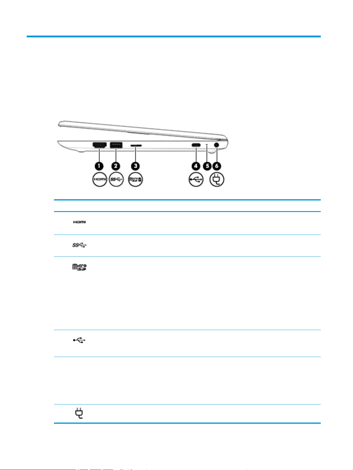
Right side
Table 2-1 Right-side components and their descriptions
Component Description
(1) HDMI port Connects an optional video or audio device, such as a high-denition television,
any compatible digital or audio component, or a high-speed High-Denition
Multimedia Interface (HDMI) device.
(2) USB SuperSpeed port Connects a USB device, such as a cell phone, camera, activity tracker, or
smartwatch, and provides high-speed data transfer.
(3) microSD memory card reader Reads optional memory cards that enable you to store, manage, share, or access
information.
To insert a card:
1. Hold the card label-side up, with connectors facing the computer.
2. Insert the card into the memory card reader, and then press in on the card
until it is rmly seated.
To remove a card:
▲ Press in on the card, and then remove it from the memory card reader.
(4) USB Type-C port Connects a USB device, such as a cell phone, camera, activity tracker, or
smartwatch, and provides data transfer.
NOTE: Cables and/or adapters (purchased separately) may be required.
(5) AC adapter and battery light ● White: The AC adapter is connected and the battery is fully charged.
● Blinking white: The AC adapter is disconnected and the battery has reached
a low battery level.
● Amber: The AC adapter is connected and the battery is charging.
● O: The battery is not charging.
(6) Power connector Connects an AC adapter.
4 Chapter 2 Getting to know your computer
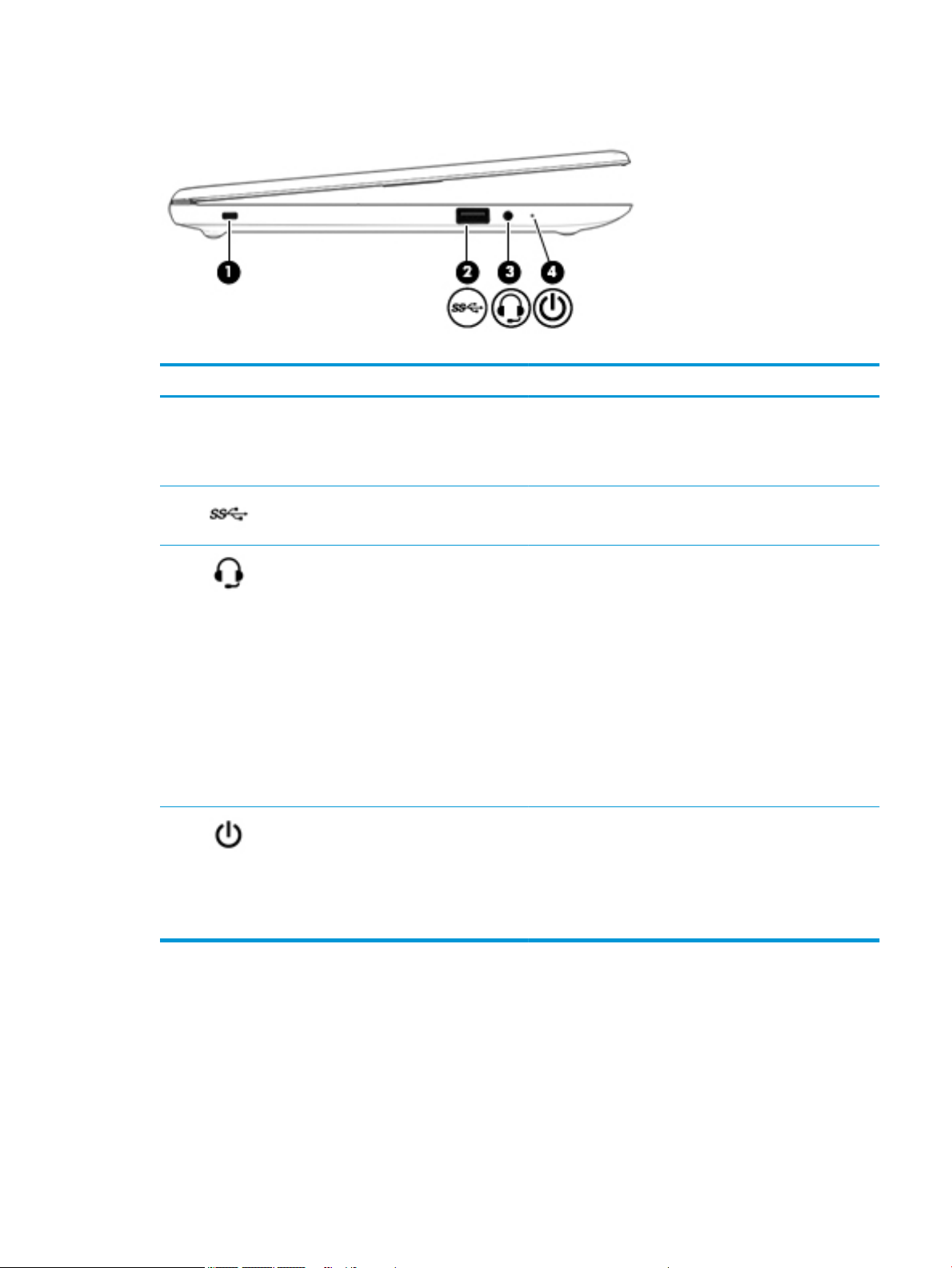
Left side
Table 2-2 Left-side components and their descriptions
Component Description
(1) Security cable slot Attaches an optional security cable to the computer.
(2) USB SuperSpeed port Connects a USB device, such as a cell phone, camera, activity
NOTE: The security cable is designed to act as a deterrent, but
it may not prevent the computer from being mishandled or
stolen.
tracker, or smartwatch, and provides high-speed data transfer.
(3) Audio-out (headphone)/Audio-in (microphone)
combo jack
(4) Power light ● On: The computer is on.
Connects optional powered stereo speakers, headphones,
earbuds, a headset, or a television audio cable. Also connects an
optional headset microphone. This jack does not support
optional standalone microphones.
WARNING! To reduce the risk of personal injury, adjust the
volume before putting on headphones, earbuds, or a headset.
For additional safety information, see the Regulatory, Safety,
and Environmental Notices.
To access this guide:
▲ Select the Start button, select HP Help and Support, and
then select HP Documentation.
NOTE: When a device is connected to the jack, the computer
speakers are disabled.
● Blinking: The computer is in the Sleep state, a power-
saving state. The computer shuts o power to the display
and other unneeded components.
● O: The computer is o or in Hibernation. Hibernation is a
power-saving state that uses the least amount of power.
Left side 5
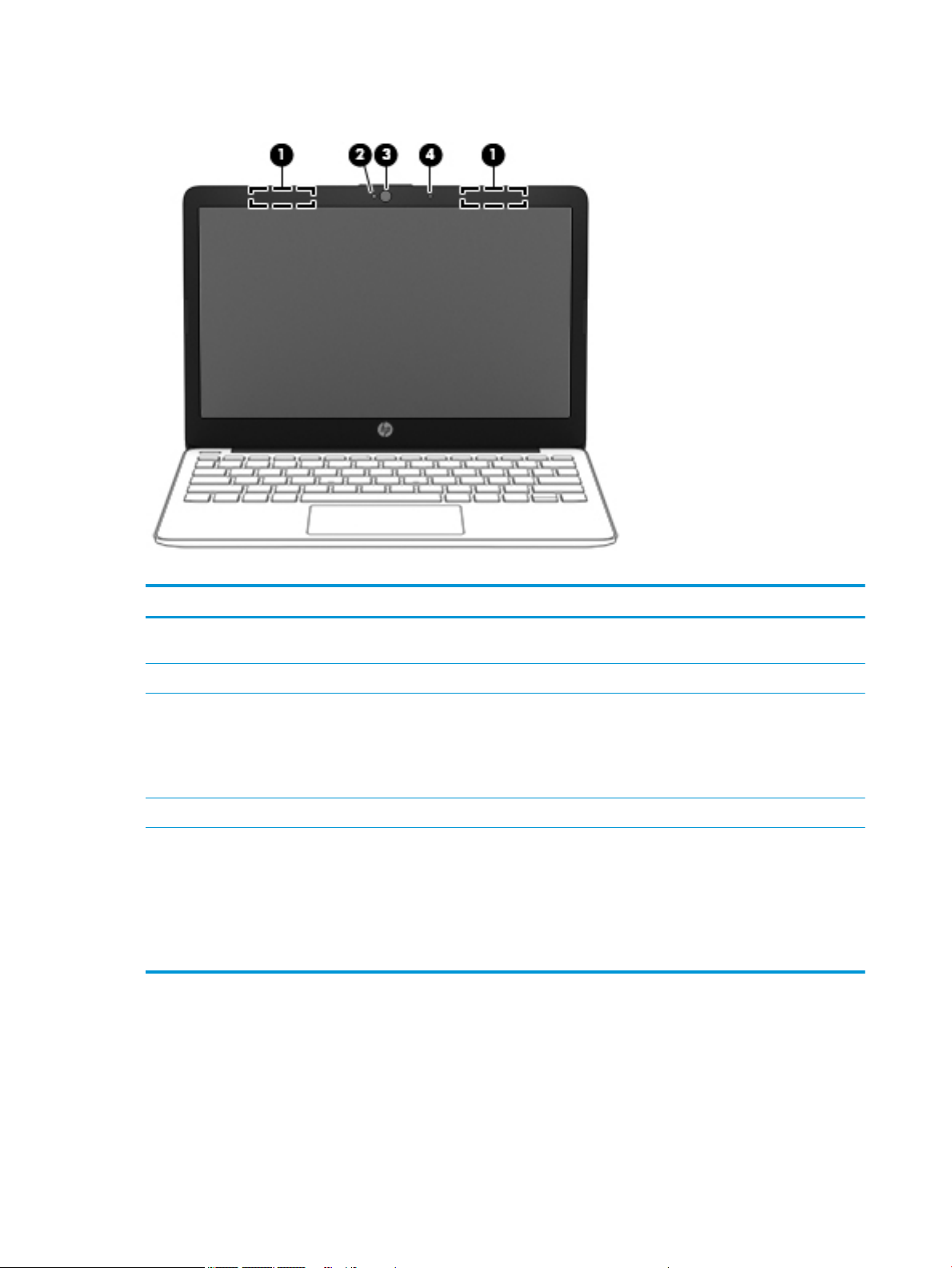
Display
Table 2-3 Display components and their descriptions
Component Description
(1) WLAN antennas* (select products only) Send and receive wireless signals to communicate with wireless local
area networks (WLANs).
(2) Camera light On: The camera is in use.
(3) Camera Allows you to video chat, record video, and record still images. Some
(4) Internal microphone Records sound.
*The antennas are not visible from the outside of the computer. For optimal transmission, keep the areas immediately around the
antennas free from obstructions.
For wireless regulatory notices, see the section of the Regulatory, Safety, and Environmental Notices that applies to your country or
region.
To access this guide:
▲ Select the Start button, select HP Help and Support, and then select HP Documentation.
cameras also allow a facial recognition logon to Windows, instead of
a password logon.
NOTE: Camera functions vary depending on the camera hardware
and software installed on your product.
6 Chapter 2 Getting to know your computer
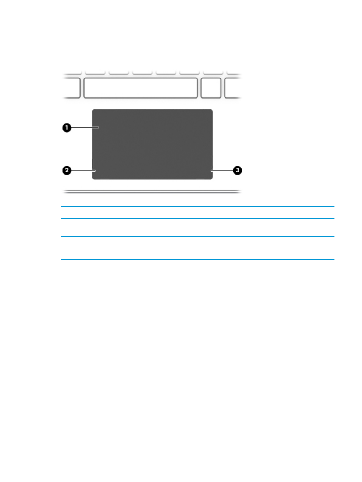
Keyboard area
Touchpad
Table 2-4 Touchpad components and their descriptions
Component Description
(1) Touchpad zone Reads your nger gestures to move the pointer or activate items
on the screen.
(2) Left control zone Textured area that allows you to perform additional gestures.
(3) Right control zone Textured area that allows you to perform additional gestures.
Keyboard area 7
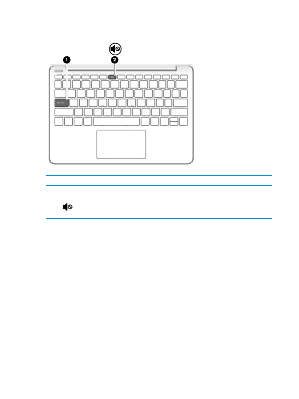
Lights
Table 2-5 Lights and their descriptions
Component Description
(1) Caps lock light On: Caps lock is on, which switches the key input to all capital
letters.
(2) Mute light ● On: Computer sound is o.
● O: Computer sound is on.
8 Chapter 2 Getting to know your computer
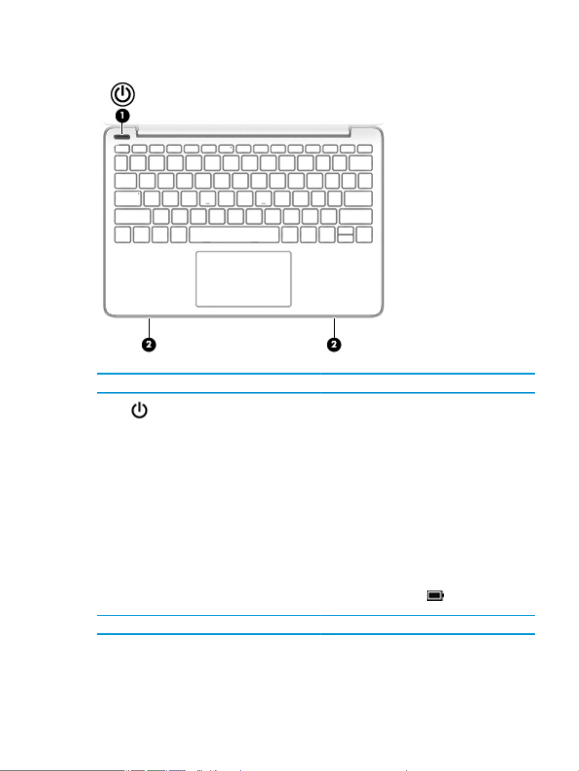
Button and speakers
Table 2-6 Buttons and speakers and their descriptions
Component Description
(1) Power button ● When the computer is o, press the button to turn on the
computer.
● When the computer is on, press the button briey to
initiate Sleep.
● When the computer is in the Sleep state, press the button
briey to exit Sleep (select products only).
● When the computer is in Hibernation, press the button
briey to exit Hibernation.
IMPORTANT: Pressing and holding down the power button
results in the loss of unsaved information.
If the computer has stopped responding and shutdown
procedures are ineective, press and hold the power button
down for at least 5 seconds to turn o the computer.
To learn more about your power settings, see your power
options:
▲ Right-click the Power icon , and then select Power
Options.
(2) Speakers (2) Produce sound.
Keyboard area 9
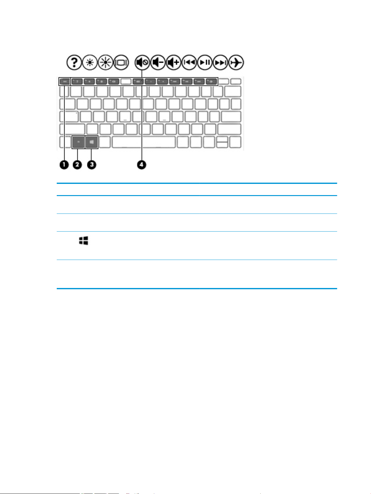
Special keys
Table 2-7 Special keys and their descriptions
Component Description
(1) esc key Displays system information when pressed in combination with
(2) fn key Executes specic functions when pressed in combination with
the fn key.
another key.
(3) Windows key Opens the Start menu.
NOTE: Pressing the Windows key again will close the Start
menu.
(4) Action keys Execute frequently used system functions.
NOTE: On select products, the f5 action key turns the keyboard
backlight feature o or on.
10 Chapter 2 Getting to know your computer
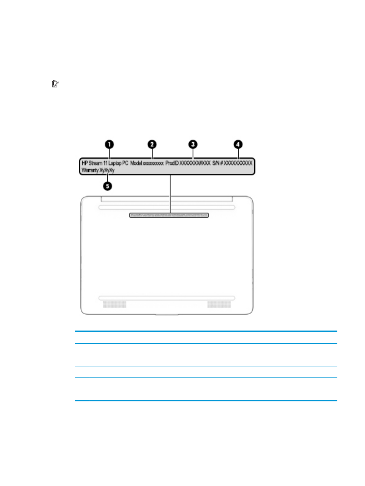
Labels
The labels axed to the computer provide information you may need when you troubleshoot system
problems or travel internationally with the computer. Labels may be in paper form or imprinted on the
product.
IMPORTANT: Check the following locations for the labels described in this section: the bottom of the
computer, inside the battery bay, under the service door, on the back of the display, or on the bottom of a
tablet kickstand.
● Service label—Provides important information to identify your computer. When contacting support, you
may be asked for the serial number, the product number, or the model number. Locate this information
before you contact support.
Table 2-8 Service label components
Component
(1) HP product name
(2) Model number
(3) Product ID
(4) Serial number
(5) Warranty period
● Regulatory label(s)—Provide(s) regulatory information about the computer.
● Wireless certication label(s)—Provide(s) information about optional wireless devices and the approval
markings for the countries or regions in which the devices have been approved for use.
Labels 11
3 Illustrated parts catalog
NOTE: HP continually improves and changes product parts. For complete and current information on
supported parts for your computer, go to http://partsurfer.hp.com, select your country or region, and then
follow the on-screen instructions.
NOTE: Details about your computer, including model, serial number, product key, and length of warranty,
are on the service tag at the bottom of your computer. See Labels on page 11 for details.
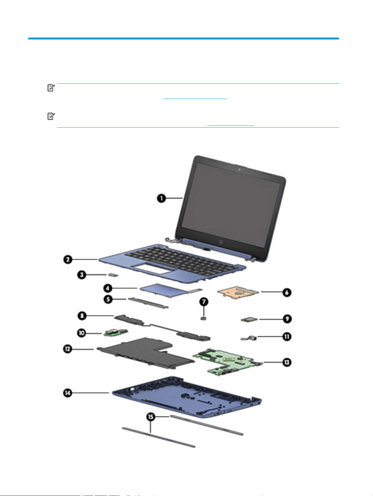
Computer major components
12 Chapter 3 Illustrated parts catalog

Table 3-1 Computer major components and their descriptions
Item Component Spare part number
(1) Display assembly: The display assembly is spared at the subcomponent level only. For more display assembly spare part
(2) Keyboard/top cover (includes keyboard cable)
Royal blue L44441-xx1
Diamond white L44642-xx1
Rose pink L45168-xx1
(3) Power button board
For use in models with a Pentium or Celeron processor L44444-001
For use in models with an Atom processor L62793-001
(4) Touchpad board (includes bracket)
Royal blue L44447-001
Diamond white L44448-001
Rose pink L44449-001
information, see Display assembly subcomponents on page 15.
For a detailed list of country codes, see Keyboard/top cover on page 22.
NOTE: The power button board spare part kit does not include the power button board
cable. The power button board cable is available as spare part number L44445-001.
NOTE: The touchpad board spare part kit does not include the touchpad board cable. The touchpad board cable is
available as spare part number L44450-001.
(5) Touchpad bracket included with touchpad
board
(6) Heat sink/thermal plate (includes replacement thermal material)
For use in models with a Pentium or Celeron processor L44446-001
For use in models with an Atom processor L61326-001
(7) Keyboard hook L48424-001
(8) Speakers (include left and right speakers and cable) L44458-001
(9) WLAN module
Realtek RTL8822BE 802.11ac 2 × 2 Wi-Fi + Bluetooth 4.2 924813-855
Realtek RTL8821CE 802.11ac 1 × 1 Wi-Fi + Bluetooth 4.2 L17365-005
Realtek RTL8822CE 802.11ac 2 × 2 Wi-Fi + Bluetooth 5.0 (MU-MIMO supported) L44796-005
(10) USB/audio board (includes audio jack and USB port)
NOTE: The connector board spare part kit does not include the connector board cable. The
connector board cable is available as spare part number L44443-001.
For use in models with a Pentium or Celeron processor L44442-001
For use in models with an Atom processor L62794-001
(11) Power connector cable L44451-001
(12) Battery (2-cell, 37 Whr, 4.96 Ahr, Li-ion; includes cable) 824536-850
Computer major components 13

Table 3-1 Computer major components and their descriptions (continued)
Item Component Spare part number
(13) System board (includes processor)
NOTE: All system board spare part kits include replacement thermal material.
System boards listed with a -xx1 part number sux use the following part numbers:
xxxxxx-001: Non-Windows operating systems
xxxxxx-601: Windows operating system
Pentium N5000 processor, 4 GB of system memory, and 32 GB of eMMC memory L44438-xx1
Celeron N4000 processor, 4 GB of system memory, and 64 GB of eMMC memory L44437-xx1
Celeron N4000 processor, 4 GB of system memory, and 32 GB of eMMC memory L44436-xx1
Celeron N4000 processor, 2 GB of system memory, and 32 GB of eMMC memory L44435-xx1
Atom x5-E8000 processor, 4 GB of system memory, and 64 GB of eMMC memory L59930-601
Atom x5-E8000 processor, 4 GB of system memory, and 32 GB of eMMC memory L59929-601
Atom x5-E8000 processor, 2 GB of system memory, and 32 GB of eMMC memory L59928-601
(14) Base enclosure
Royal blue L44452-001
Diamond white L44453-001
Rose pink L44454-001
(15) Rubber Feet Kit
Royal blue L44455-001
Diamond white L44456-001
Rose pink L44457-001
14 Chapter 3 Illustrated parts catalog
 Loading...