

Page 1

HP Stream Laptop PC, HP Stream 11 Pro G4
Notebook PC Education Edition, and HP
Stream 11 Pro G3 Notebook PC
Maintenance and Service Guide
IMPORTANT! This document is intended for
HP authorized service providers only.
Page 2

© Copyright 2018 HP Development Company,
L.P.
Bluetooth is a trademark owned by its
proprietor and used by HP Inc. under license.
DTS, the Symbol, & DTS and the Symbol
together are registered trademarks, and DTS
Sound is a trademark of DTS, Inc. © DTS, Inc. All
Rights Reserved. Intel and Celeron are
trademarks of Intel Corporation in the U.S.
and other countries. SD Logo is a trademark of
its proprietor.
The information contained herein is subject to
change without notice. The only warranties for
HP products and services are set forth in
the express warranty statements
accompanying such products and services.
Nothing herein should be construed as
constituting an additional warranty. HP shall
not be liable for technical or editorial errors or
omissions contained herein.
Fourth Edition: May 2018
First Edition: October 2016
Document Part Number: 902298-004
Product notice
This guide describes features that are common
to most models. Some features may not be
available on your computer.
Not all features are available in all editions of
Windows 10. This computer may require
upgraded and/or separately purchased
hardware, drivers, and/or software to take full
advantage of Windows 10 functionality. See
http://www.microsoft.com for details.
Page 3

Safety warning notice
WARNING! To reduce the possibility of heat-related injuries or of overheating the device, do not place
the device directly on your lap or obstruct the device air vents. Use the device only on a hard, at surface. Do
not allow another hard surface, such as an adjoining optional printer, or a soft surface, such as pillows or rugs
or clothing, to block airow. Also, do not allow the AC adapter to contact the skin or a soft surface, such as
pillows or rugs or clothing, during operation. The device and the AC adapter comply with the user-accessible
surface temperature limits dened by the International Standard for Safety of Information Technology
Equipment (IEC 60950-1).
iii
Page 4

iv Safety warning notice
Page 5

Table of contents
1 Product description ....................................................................................................................................... 1
2 External component identication .................................................................................................................. 8
Display .................................................................................................................................................................... 8
Button .................................................................................................................................................................... 9
TouchPad .............................................................................................................................................................. 10
Left side ............................................................................................................................................................... 11
Right side ............................................................................................................................................................. 12
Bottom ................................................................................................................................................................. 13
Locating the serial number, model number, product number, and warranty information ............................... 13
3 Illustrated parts catalog .............................................................................................................................. 15
Computer major components .............................................................................................................................. 16
Display assembly subcomponents ...................................................................................................................... 19
Miscellaneous parts ............................................................................................................................................. 20
4 Removal and replacement preliminary requirements ..................................................................................... 22
Tools required ...................................................................................................................................................... 22
Service considerations ......................................................................................................................................... 22
Plastic parts ....................................................................................................................................... 22
Cables and connectors ...................................................................................................................... 22
Drive handling ................................................................................................................................... 23
Grounding guidelines ........................................................................................................................................... 24
Electrostatic discharge damage ........................................................................................................ 24
Packaging and transporting guidelines .......................................................................... 25
Workstation guidelines ................................................................................ 25
5 Removal and replacement procedures ........................................................................................................... 27
Component replacement procedures .................................................................................................................. 27
Computer feet ................................................................................................................................... 27
Keyboard/top cover ........................................................................................................................... 28
Speakers ............................................................................................................................................ 33
RTC battery (select products only) .................................................................................................... 34
Battery ............................................................................................................................................... 36
WLAN module .................................................................................................................................... 37
Heat sink ............................................................................................................................................ 40
v
Page 6

System board .................................................................................................................................... 42
Connector board ................................................................................................................................ 46
Power connector ............................................................................................................................... 48
Power button board .......................................................................................................................... 49
TouchPad board ................................................................................................................................. 50
Display assembly ............................................................................................................................... 52
Base enclosure .................................................................................................................................. 57
6 Using Setup Utility (BIOS) ............................................................................................................................. 58
Starting Setup Utility (BIOS) ................................................................................................................................ 58
Updating Setup Utility (BIOS) .............................................................................................................................. 58
Determining the BIOS version ........................................................................................................... 58
Downloading a BIOS update .............................................................................................................. 59
7 Using HP PC Hardware Diagnostics ................................................................................................................ 60
Using HP PC Hardware Diagnostics Windows ..................................................................................................... 60
Downloading HP PC Hardware Diagnostics Windows ....................................................................... 60
Downloading the latest HP PC Hardware Diagnostics Windows version ....................... 61
Downloading HP Hardware Diagnostics Windows by product name or number
(select products only) ..................................................................................................... 61
Installing HP PC Hardware Diagnostics Windows ............................................................................. 61
Using HP PC Hardware Diagnostics UEFI ............................................................................................................. 61
Starting HP PC Hardware Diagnostics UEFI ....................................................................................... 62
Downloading HP PC Hardware Diagnostics UEFI to a USB ash drive .............................................. 62
Downloading the latest HP PC Hardware Diagnostics UEFI version .............................. 62
Downloading HP PC Hardware Diagnostics UEFI by product name or number
(select products only) ..................................................................................................... 62
Using Remote HP PC Hardware Diagnostics UEFI settings (select products only) ............................................. 63
Downloading Remote HP PC Hardware Diagnostics UEFI ................................................................. 63
Downloading the latest Remote HP PC Hardware Diagnostics UEFI version ................. 63
Downloading Remote HP PC Hardware Diagnostics UEFI by product name or
number ............................................................................................................................ 63
Customizing Remote HP PC Hardware Diagnostics UEFI settings .................................................... 63
8 Specications .............................................................................................................................................. 65
9 Backing up, restoring, and recovering ........................................................................................................... 66
Using Windows tools ........................................................................................................................................... 66
Creating HP Recovery media (select products only) ........................................................................................... 66
Using HP Recovery Manager to create recovery media .................................................................... 67
Before you begin ............................................................................................................. 67
vi
Page 7

Creating the recovery media ........................................................................................... 67
Using the HP Cloud Recovery Download Tool to create recovery media .......................................... 68
Restoring and recovery ........................................................................................................................................ 68
Restoring, resetting, and refreshing using Windows tools .............................................................. 68
Restoring using HP Recovery Manager and the HP Recovery partition ........................................... 68
Recovering using HP Recovery Manager ........................................................................................... 68
Recovering using the HP Recovery partition (select products only) ................................................ 69
Recovering using HP Recovery media ............................................................................................... 69
Changing the computer boot order ................................................................................................... 70
Removing the HP Recovery partition (select products only) ............................................................ 70
10 Power cord set requirements ...................................................................................................................... 71
Requirements for all countries ............................................................................................................................ 71
Requirements for specic countries and regions ................................................................................................ 72
11 Recycling .................................................................................................................................................. 74
Index ............................................................................................................................................................. 75
vii
Page 8

viii
Page 9

1 Product description
Category Details HP Stream Laptop
PC with Intel
Celeron N4000
Product Name HP Stream Laptop PC √ √
HP Stream 11 Pro G4
Education Edition
Notebook PC
HP Stream 11 Pro G3
Notebook PC
Processor Intel® Celeron™ N4000
(1.1 GHZ turbo up to 2.6
GHz) 2400 MHz/4 MB L2,
Dual SDP 4.8 W
Intel Celeron N3450 1.1
GHz (turbo up to 2.2 GHz)
dual core processor,
(1866 MHz FSB, 2 MB L2
cache, dual SDP, 4 W)
Intel Celeron N3350 1.1
GHz (turbo up to 2.4 GHz)
dual core processor,
(1866 MHz FSB, 2 MB L2
cache, dual SDP, 4 W)
√
√
√
√
√ √ √
HP Stream 11 Pro
G4 Education
Edition Notebook
PC
HP Stream 11 Pro
G3 Notebook PC
HP Stream
Laptop PC with
Intel Celeron
N3XXX
Intel Celeron N3060 1.66
GHz (turbo up to 2.48
GHz) dual core processor,
(1600 MHz FSB, 2 MB L2
cache, Dual SDP, 4 W)
Intel Celeron N3050 1.66
GHz (turbo up to 2.16
GHz) dual core processor,
(1600 MHz FSB, 2 MB L2
cache, Dual SDP, 4 W)
Chipset Intel integrated soldered-
on-circuit (SoC)
Graphics
Supports HD
decode, DX11,
and HDMI
Panel 11.6 in, high-denition
Internal Graphics:
Intel UHD Graphics 600
Intel HD Graphics 400 √ √ √
Intel HD Graphics √ √
(HD), 16:9 aspect ratio;
typical brightness: 220
nits
√ √
√ √
√ √ √ √
√
√ √ √ √
1
Page 10

Category Details HP Stream Laptop
PC with Intel
Celeron N4000
HP Stream 11 Pro
G4 Education
Edition Notebook
PC
HP Stream 11 Pro
G3 Notebook PC
HP Stream
Laptop PC with
Intel Celeron
N3XXX
AntiGlare (1366×768),
slim, SVA, white lightemitting diode (WLED),
at (3.0 mm); eDP; touch,
TOP solution, multitouch
enabled
AntiGlare (1366×768),
slim, SVA, white lightemitting diode (WLED),
at (3.0 mm); eDP; nontouch
BrightView (1366×768),
slim, UWVA, white lightemitting diode (WLED),
at (1.2 mm); touch
Memory Supports up to 4.0 GB
maximum on-board
system memory
Supports DDR4-2400
Single Channel Support
on-board 2.0 GB system
memory
2048 MB (256 MB × 16 × 4
pieces)
Supports DDR4-2400
Dual Channel Support onboard 2.0 GB system
memory
409 6MB (25 6MB x16 x 8
pieces)
√
√ √ √
√
√ √ √ √
√
√
Supports DDR3L-1600
single channel on-board
2.0 GB system memory
2048 MB (256 MB × 16 × 4
pieces)
Supports DDR3L-1600
dual channel on-board
4.0 GB system memory
4096 MB (256 MB × 16 × 8
pieces)
Storage
Embedded
MultiMedia
Controller (eMMC)
congurations
Audio and video HP VGA camera, USB 2.0
32 GB √ √ √ √
64 GB (only available for 4
GB memory systems)
128 GB √
xed (no tilt) integrated
activity light, 640×480 by
24 frames per second,
2 Chapter 1 Product description
√ √
√ √ √
√ √ √
√ √ √ √
Page 11

Category Details HP Stream Laptop
PC with Intel
Celeron N4000
camera with rubber for
non-touch
Single digital microphone
with appropriate beamforming, echocancellation, noisesuppression software
Two speakers
DTS Studio Sound
Enable HP Noise
Cancellation
HP Stream 11 Pro
G4 Education
Edition Notebook
PC
HP Stream 11 Pro
G3 Notebook PC
HP Stream
Laptop PC with
Intel Celeron
N3XXX
Wireless Integrated wireless local
area network (WLAN)
options by way of wireless
module
Supports the following
WLAN modules:
Two built-in WLAN
antennas
Intel Dual Band AC 7265
802.11 AC 2×2 WiFi +
Bluetooth 4.2
Combo Adapter (nonvPro)
Intel Dual band wirelessAC 3168 802.11AC 1x1
WiFi + BT 4.2 Combo
Adaptor (non-vPro)
One built-in WLAN
antenna
Realtek RTL8822BE
802.11 ac 2x2 WiFi + BT
4.2 Combo Adapter (MUMIMO supported)
Realtek RTL8723BE-VB
802.11b/g/n 1x1 Wi-Fi +
BT4.0 Combo Adapter
√ √ √ √
√ √ √
√
√
√ √
√
Ports HP Smart Plug AC adapter
(4.0 mm barrel)
Headphone/microphone
combo jack
High-denition
multimedia interface
(HDMI) v.1.4b, supporting
up to 1080b, 1920×1080
at 60 Hz
USB 3.0 port
√ √ √ √
3
Page 12

Category Details HP Stream Laptop
PC with Intel
Celeron N4000
USB 2.0 port
HP Stream 11 Pro
G4 Education
Edition Notebook
PC
HP Stream 11 Pro
G3 Notebook PC
HP Stream
Laptop PC with
Intel Celeron
N3XXX
External media
cards
Keyboard/pointing
devices
Power
requirements
HP 2-in-1 multiformat
Digital Media Reader Slot
with push-push
technology. Reads data
from and writes data to
digital memory cards
such as micro SD/SDHC/
SDXC.
Full-sized, textured,
island-style, keyboard
TouchPad requirements:
Clickpad with image
sensor
Multitouch gestures
enabled (2-nger scroll,
pinch, rotate, 2-nger
click, 3-nger ic)
Support for modern
trackpad gestures
Taps enabled as default
Supports a 2-cell, 37.69
WH, polymer battery
Supports 65 W HP Smart
AC adapter (non-PFC, EM,
4.5 mm)
√ √ √ √
√ √ √ √
√ √ √ √
√ √ √
Supports 45 W HP Smart
AC adapter (non-PFC, RC,
4.5 mm)
Security Trusted platform module
(TPM) 2.0
Security cable lock
Operating system Preinstalled:
Windows 10
For developed market
(ML)
Windows 10 Home in S
Mode (Entry)
Windows 10 Home in S
Mode (Value)
√ √ √ √
√ √ √ √
√ √ √ √
√
VC Rule: ≤14.1" +
Low CPU (N4000)
= 4 GB + 32 GB
SSD/eMMC + no
ODD + no HDD
√
VC Rule: ≤14.1" +
Low CPU (N4000)
4 Chapter 1 Product description
Page 13

Category Details HP Stream Laptop
PC with Intel
Celeron N4000
= 4 GB + 64 GB
SSD/eMMC
HP Stream 11 Pro
G4 Education
Edition Notebook
PC
HP Stream 11 Pro
G3 Notebook PC
HP Stream
Laptop PC with
Intel Celeron
N3XXX
Windows 10 Home in S
Mode (Entry) MS
Signature
Windows 10 Home Entry
NB
Windows 10 Home Value
NB
Windows 10 Home Entry
NB
√
VC Rule: Celeron
N4000 DC / 4 GB /
11" HD IPS / 32 GB
eMMC
√
√
√
<=14" / Low CPU
(N3050) / ≤4GB /
32GB SSD or
eMMC / no ODD /
OneDrive100GB/2
yr
<=14" / Low CPU
(N3050) / ≤4GB /
32GB SSD or
eMMC / no ODD /
OneDrive100GB/2
yr
<=14" / Low CPU
(N3050) / ≤4GB /
32GB SSD or
eMMC / no ODD /
OneDrive100GB/2
yr
√
<=14" / Low CPU
(N3050) / ≤4GB /
32GB SSD or
eMMC / no ODD /
OneDrive100GB/2
yr
√
<=14" / Low CPU
(N3050) / ≤4GB /
32GB SSD or
eMMC / no ODD /
OneDrive100GB/2
yr
√
<=14" / Low CPU
(N3050) / ≤4GB /
32GB SSD or
eMMC / no ODD /
OneDrive100GB/2
yr
Windows 10 Home Entry
NB with OneDrive
Windows 10 Home Entry
NB with Oce 365
Personal (AFO)
For emerging Market
(EM/SL)
Windows 10 Home Entry
NB with OneDrive
√
<=14" / Low CPU
(N3050) / ≤4GB /
32GB SSD or
eMMC / no ODD /
OneDrive100GB/2
yr
√
<=14" / Low CPU
(N3060) / ≤4GB /
32GB SSD or
eMMC / no ODD)
√
<=14" / Low CPU
(N3050) / ≤4GB /
32GB SSD or
eMMC / no ODD /
<=14" / Low CPU
(N3050) / ≤4GB /
32GB SSD or
eMMC / no ODD /
OneDrive100GB/2
<=14" / Low CPU
(N3060) / ≤4GB /
32GB SSD or
eMMC / no ODD)
<=14" / Low CPU
(N3050) / ≤4GB /
32GB SSD or
eMMC / no ODD /
√
yr
√
√
5
Page 14

Category Details HP Stream Laptop
PC with Intel
Celeron N4000
HP Stream 11 Pro
G4 Education
Edition Notebook
PC
HP Stream 11 Pro
G3 Notebook PC
OneDrive100GB/2yrOneDrive100GB/2
HP Stream
Laptop PC with
Intel Celeron
N3XXX
yr
SEAP Windows 10 Home
Entry NB
Windows 10 Home Entry
NB with OneDrive
Windows 10 Home Entry
NB
SEAP Windows 10 Home
Entry NB with OneDrive
Windows 10 Home Entry
NB with Oce 365
Personal (AFO)
Windows 10 Home Entry
NB with Oce 365
Personal (AFO)
Windows 10 Pro 64
Compact
√
√
√
√
√
<=14" / Low CPU
(N3050) / ≤4GB /
32GB SSD or
eMMC / no ODD /
OneDrive100GB/2
yr
√
<=14" / Low CPU
(N3060) / ≤4GB /
32GB SSD or
eMMC / no ODD)
√
Windows 10 Pro 64 StF
MSNA Compact
Windows 10 Pro 64 StF
MSNA EM Compact
Windows 10 Pro 64 StF
MSNA Strategic Compact
Windows 10 Pro 64 Value
Notebook Compact
Windows 10 S 64 Value
Compact
√
√
√
√
RAM equal to or
less than 4GB AND
(Storage equal to
or less than 64GB
SSD or Storage
Equal to or less
than 64GB eMMC)
√
RAM equal to or
less than 4GB AND
(Storage equal to
or less than 64GB
SSD or Storage
Equal to or less
than 64GB eMMC)
6 Chapter 1 Product description
Page 15

Category Details HP Stream Laptop
PC with Intel
Celeron N4000
HP Stream 11 Pro
G4 Education
Edition Notebook
PC
HP Stream 11 Pro
G3 Notebook PC
HP Stream
Laptop PC with
Intel Celeron
N3XXX
Web Support
Windows 10 Enterprise
Serviceability End-user replaceable
parts:
AC adapter
√
√ √ √ √
7
Page 16
2 External component identication
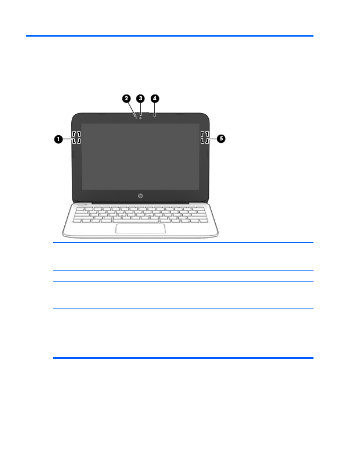
Display
Item Component Description
(1) WLAN antenna* Sends and receives wireless signals to communicate with
(2) Camera light On: The camera is in use.
(3) Camera Records video and captures photographs. Some models allow
(4) Internal microphone Records sound.
(5) WLAN antenna* (select products only) Sends and receives wireless signals to communicate with
*The antennas are not visible from the outside of the computer. For optimal transmission, keep the areas immediately around
the antennas free from obstructions.
For wireless regulatory notices, see the section of the Regulatory, Safety, and Environmental Notices that applies to your country
or region.
wireless local area networks (WLANs).
you to video conference and chat online using streaming video.
wireless local area networks (WLANs).
8 Chapter 2 External component identication
Page 17
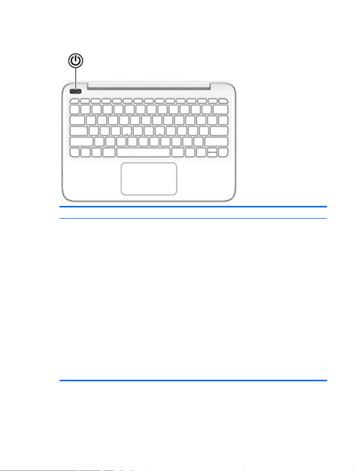
Button
Item Component Description
Power button ● When the computer is o, press the button to turn on the
computer.
● When the computer is on, press the button briey to initiate
Sleep.
● When the computer is in the Sleep state, press the button
briey to exit Sleep.
● When the computer is in Hibernation, press the button
briey to exit Hibernation.
CAUTION: Pressing and holding down the power button results
in the loss of unsaved information.
If the computer has stopped responding and shutdown
procedures are ineective, press and hold the power button
down for at least 5 seconds to turn o the computer.
To learn more about your power settings, see your power
options.
▲ Type power in the taskbar search box, and then select
Power and sleep settings.
‒ or –
Right-click the Start button, and then select Power
Options.
Button 9
Page 18
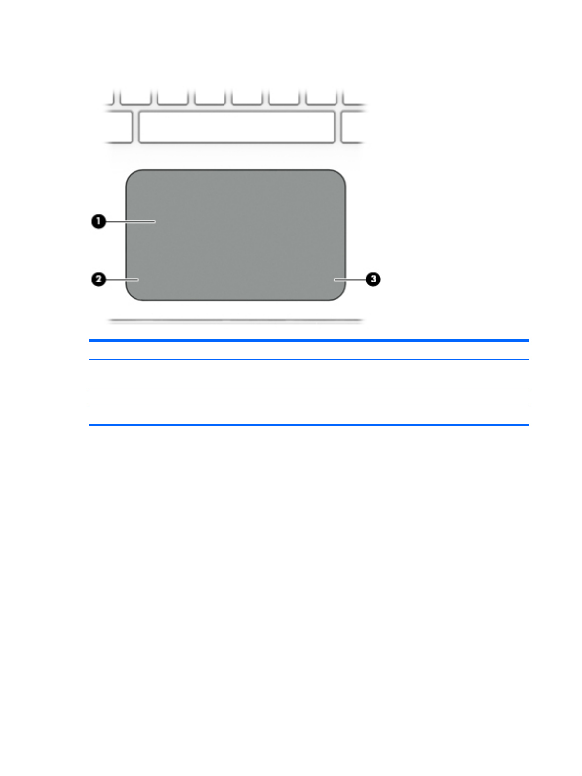
TouchPad
Item Component Description
(1) TouchPad zone Reads your nger gestures to move the pointer or activate items
on the screen.
(2) Left TouchPad button Functions like the left button on an external mouse.
(3) Right TouchPad button Functions like the right button on an external mouse.
10 Chapter 2 External component identication
Page 19
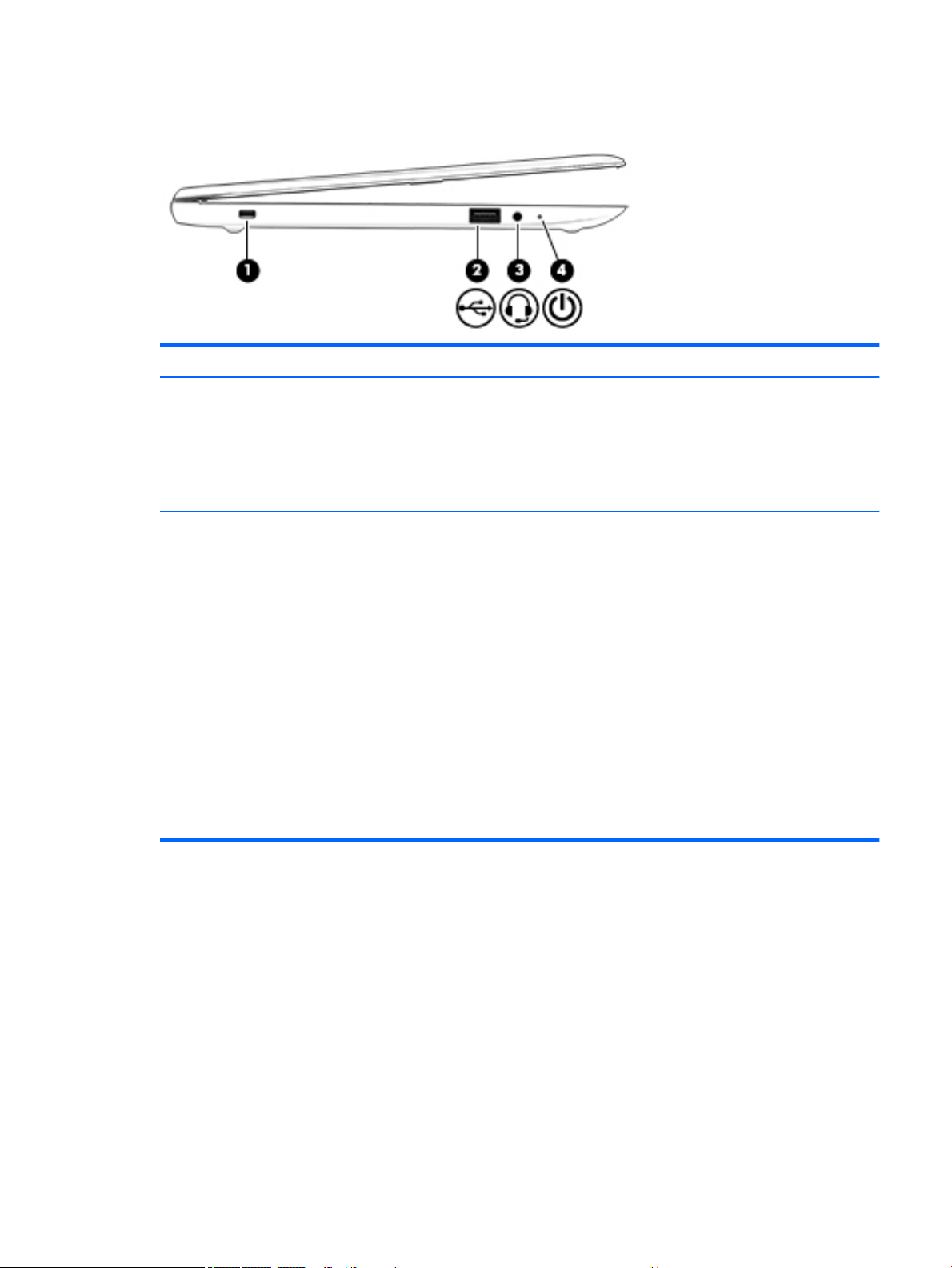
Left side
Item Component Description
(1) Security cable slot Attaches an optional security cable to the computer.
(2) USB 2.0 port Connects an optional USB device, such as a keyboard, mouse,
(3) Audio-out (headphone)/audio-in (microphone) combo jack Connects optional powered stereo speakers, headphones,
NOTE: The security cable is designed to act as a deterrent,
but it may not prevent the computer from being mishandled
or stolen.
external drive, printer, scanner or USB hub.
earbuds, a headset, or a television audio cable. Also connects an
optional headset microphone. This jack does not support
optional microphone-only devices.
WARNING! To reduce the risk of personal injury, adjust
the volume before putting on headphones, earbuds, or a
headset. For additional safety information, refer to
the Regulatory, Safety, and Environmental Notices.
NOTE: When a device is connected to the jack, the computer
speakers are disabled.
(4) Power light ● On: The computer is on.
● Blinking: The computer is in the Sleep state, a power-saving
state. The computer shuts o power to the display and
other unneeded components.
● O: The computer is o or in Hibernation. Hibernation is a
power-saving state that uses the least amount of power.
Left side 11
Page 20
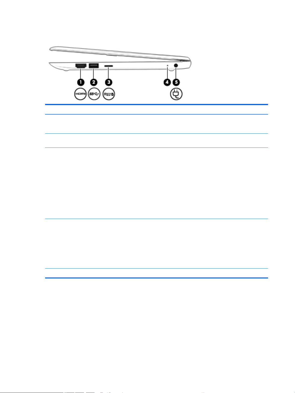
Right side
Item Component Description
(1) HDMI port Connects an optional video or audio device, such as a high-
(2) USB 3.0 port Connects an optional USB device, such as a keyboard, mouse,
(3) Memory card reader Reads optional memory cards that enable you to store, manage,
denition television, any compatible digital or audio component,
or a high-speed HDMI device.
external drive, printer, scanner or USB hub.
share, or access information.
To insert a card:
1. Hold the card label-side up, with connectors facing
the computer.
2. Insert the card into the memory card reader, and then press
in on the card until it is rmly seated.
To remove a card:
▲ Press in on the card, and then remove it from the memory
card reader.
(4) AC adapter/battery light ● White: The AC adapter is connected and the battery is
fully charged.
● Blinking white: The AC adapter is disconnected and
the battery has reached a low battery level.
● Amber: The AC adapter is connected and the battery
is charging.
● O: The battery is not charging.
(5) Power connector Connects an AC adapter.
12 Chapter 2 External component identication
Page 21
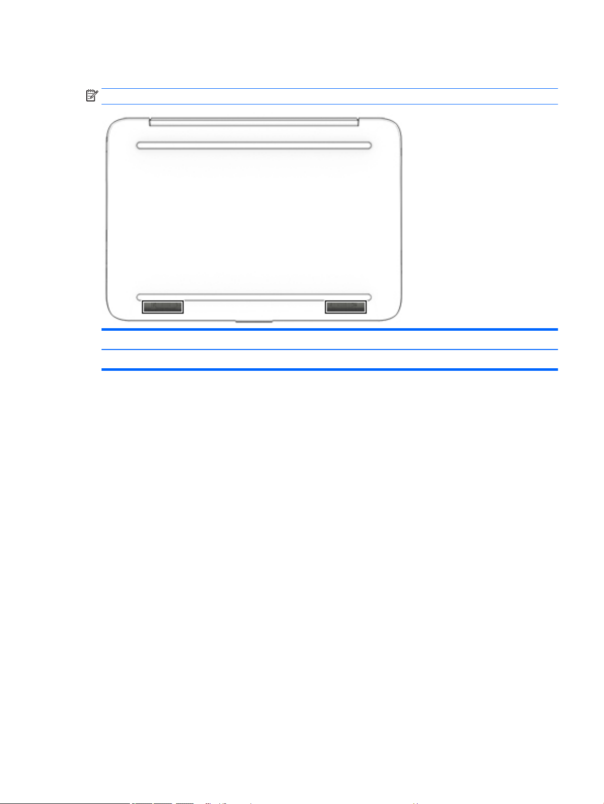
Bottom
NOTE: The bottom for your computer may dier from the illustration.
Item Component Description
Speakers Produce sound.
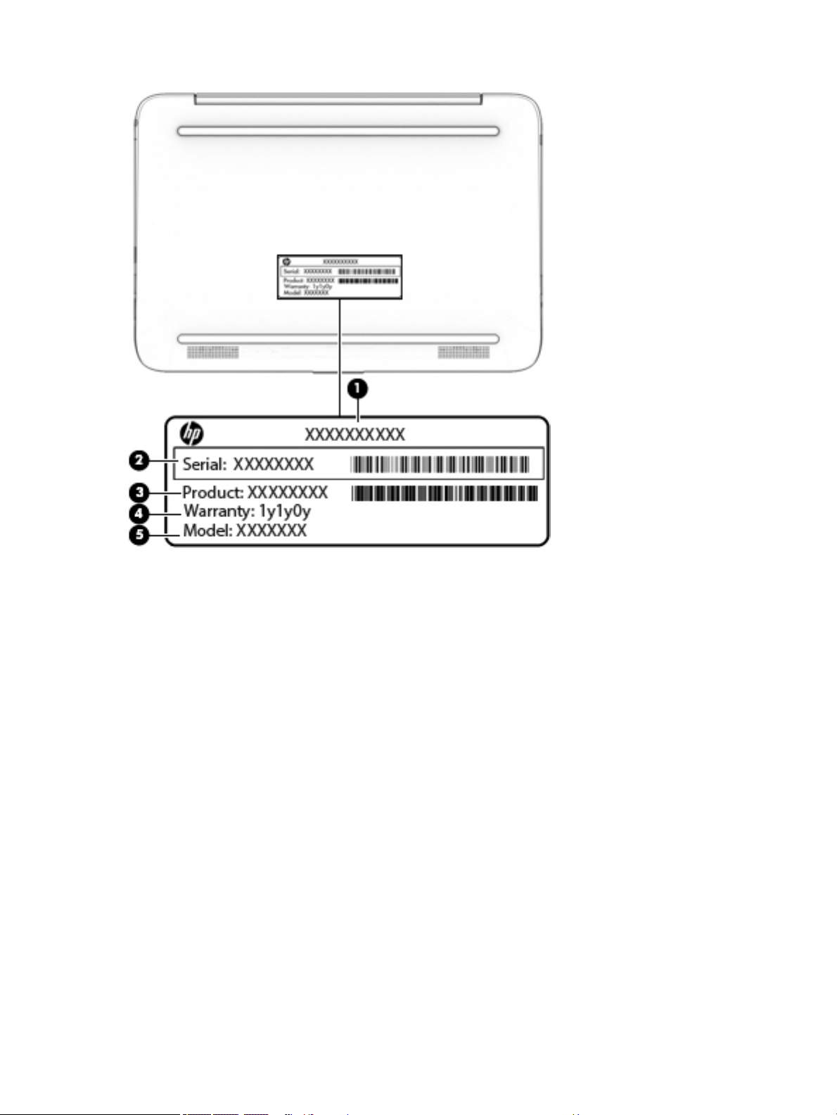
Locating the serial number, model number, product number, and warranty information
The product name (1), serial number (2), product number (3), warranty information (4), and
model number (5), are located on the bottom of the computer. This information may be needed when
travelling internationally or when contacting support.
Bottom 13
Page 22
14 Chapter 2 External component identication
Page 23

3 Illustrated parts catalog
NOTE: HP continually improves and changes product parts. For complete and current information on
supported parts for your computer, go to http://partsurfer.hp.com, select your country or region, and then
follow the on-screen instructions.
15
Page 24
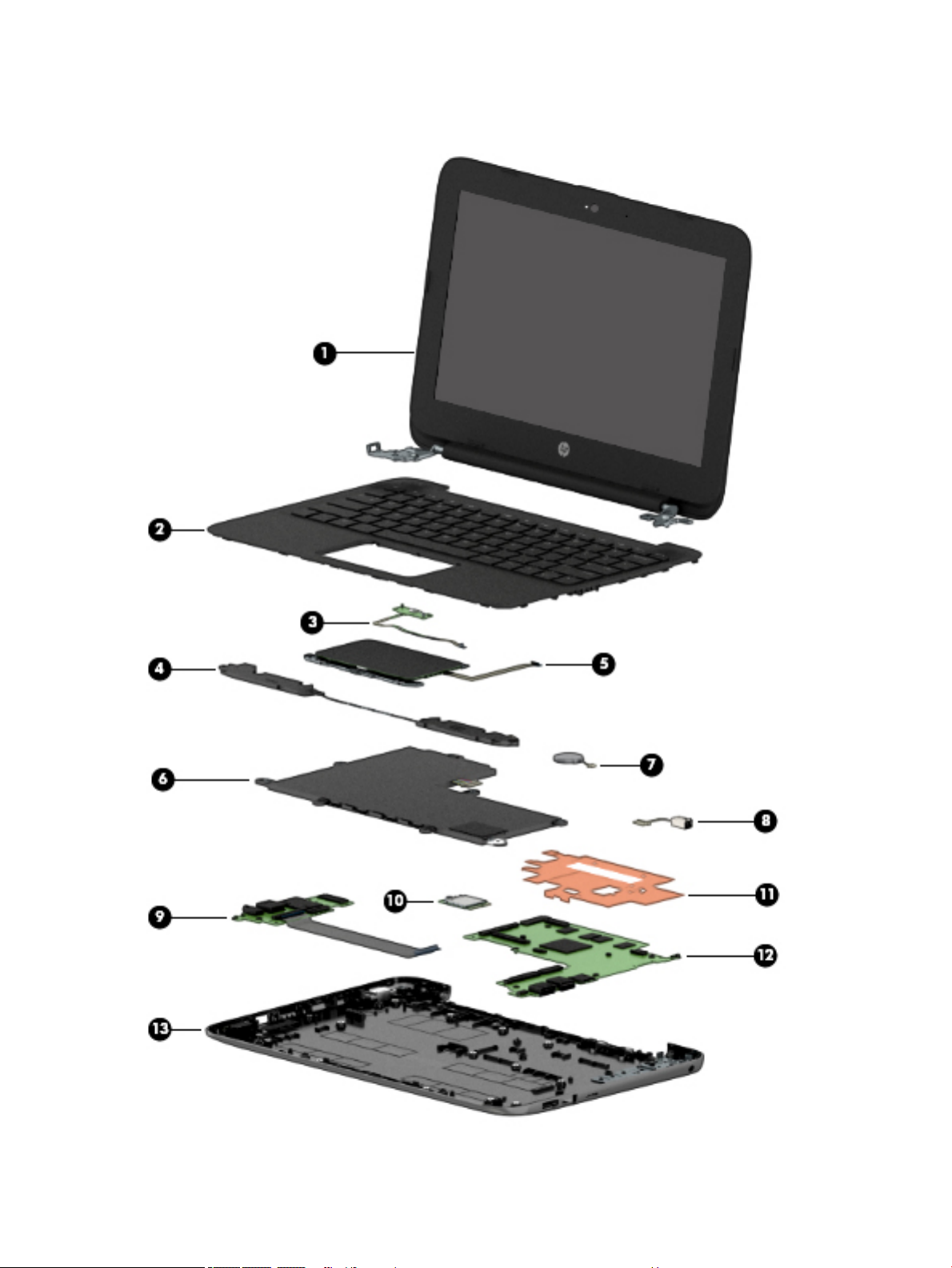
Computer major components
16 Chapter 3 Illustrated parts catalog
Page 25

Item Component Spare part number
(1) Display assembly: The display assembly is spared at the subcomponent level only. For more display assembly spare part
information, see Display assembly subcomponents on page 19.
(2) Keyboard/top cover (includes keyboard cable). For a complete list of keyboard/top covers see Keyboard/top cover
on page 28.
(3) Power button board
NOTE: The power button board spare part kit does not include the power button board
cable. The power button board cable is available using spare part number 830757-001.
(4) Speakers (include left and right speakers and cables) 902964-001
(5) TouchPad board (includes double-sided adhesive). For a complete list of TouchPad board descriptions see TouchPad board
on page 50
NOTE: The TouchPad board spare part kit does not include the TouchPad board cable. The TouchPad board cable is
available using spare part number 830763-001.
TouchPad bracket 908302-001
(6) Battery (2-cell, 37 WH, 4.96 AH, Li-ion; includes cable) 824536-850
(7) RTC battery (includes cable and double-sided adhesive), HP Stream Laptop PC with Intel
Celeron N3XXX only
(8) Power connector 743480-004
(9) Connector board (includes audio jack and USB port)
NOTE: The connector board spare part kit does not include the connector board cable. The
connector board cable is available using spare part number 830759-001.
(10) WLAN module:
Intel Dual Band Wireless-AC 7265 802.11 AC 2×2 WiFi + Bluetooth 4.2 Combo Adapter D1
(HP Stream Laptop PC with Intel Celeron N4000 only)
902958-001
830764-001
902960-001
901229-855
Intel Dual Band Wireless-AC 7265 802.11 AC 2×2 WiFi + Bluetooth 4.2 Combo Adapter D0 793840-005
Realtek RTL8822BE 802.11 ac 2x2 WiFi + BT 4.2 Combo Adapter (MU-MIMO supported) 924813-855
(11) Heat sink (includes replacement thermal material) 902899-001
(12) System board (includes HDMI port, micro-SD card reader slot, USB port, WLAN slot, LVDS slot, DC in slot, and replacement
thermal material). For a complete list of system board descriptions see System board on page 42.
(13) Base enclosure:
For use on HP Stream Laptop PC models only
Aqua blue nish 902949-001
Innity purple nish (only models with Intel Celeron N400 or Intel Celeron N3XXX) L23671-001
Neon pink nish (only models with Intel Celeron N400) L23672-001
Snow white nish 910457-001
Smoke gray nish (only models with Intel Celeron N400) L32380-001
Violet purple nish (only models with Intel Celeron N3XXX) 902950-001
For use on HP Stream Laptop PC models with Intel Celeron N400 and HP Stream 11 Pro G3
Notebook PC models only
Jack black nish 908300-001
Computer major components 17
Page 26

Item Component Spare part number
For use on HP Stream Laptop PC models with Intel Celeron N400 and HP Stream 11 Pro G4
Education Edition Notebook PC models only
Rubber Kit not illustrated, includes rubber feet (top and bottom)
For use on HP Stream Laptop PC models only
Innity purple nish (only models with Intel Celeron N400 or Intel Celeron N3XXX) L23675-001
Neon pink nish (only models with Intel Celeron N400) L23676-001
Snow white nish 910461-001
Aqua blue nish 902961-001
Smoke gray nish (only models with Intel Celeron N400) L02783-001
Violet purple nish (only models with Intel Celeron N3XXX) 902962-001
For use on HP Stream 11 Pro G4 Education Edition Notebook PC models only L02779-001
For use on HP Stream Laptop PC models with Intel Celeron N400 and HP Stream 11 Pro G3
Notebook PC models only
Jack black nish 908303-001
L02780-001
18 Chapter 3 Illustrated parts catalog
Page 27

Display assembly subcomponents
Item Component Spare part number
(1) Display bezel:
For use on HP Stream Laptop PC models only
Innity purple nish (only models with Intel Celeron N400 or Intel Celeron N3XXX) L23673-001
Neon pink nish (only models with Intel Celeron N400) L23674-001
Snow white nish 910458-001
Aqua blue nish 902951-001
Smoke gray nish (only models with Intel Celeron N400) L32381-001
Display assembly subcomponents 19
Page 28

Item Component Spare part number
Violet purple nish (only models with Intel Celeron N3XXX) 902952-001
For use on HP Stream Laptop PC models with Intel Celeron N400 and HP Stream 11 Pro G3
Notebook PC models only
Jack black nish 908298-001
For use on HP Stream 11 Pro G4 Education Edition Notebook PC models only L02784-001
(2) Display panel:
For use on HP Stream Laptop PC models only
11.6 in, HD, AntiGlare (1366×768), SVA, WLED, slim (3.0 mm) 902900-001
For use on HP Stream 11 Pro G4 Education Edition Notebook PC models only
11.6 in, HD, BrightView (1366×768), slim, UWVA, WLED, at (1.2 mm); touch L04050-001
11.6 in, HD, AntiGlare (1366×768), SVA, WLED, slim (3.0 mm) L02782-001
(3) Camera/microphone module (includes double-sided adhesive) 902905-001
(4) Display Hinge Kit (includes left and right display hinges) 902955-001
(5) Display panel cable (includes camera/microphone module cable) 902953-001
(6) WLAN antenna (includes left and right WLAN cables and transceivers) 902946-001
(7) Display enclosure/Back cover (includes rubber padding, antenna, and shielding):
For use on HP Stream Laptop PC models only
Innity purple nish (only models with Intel Celeron N400 or Intel Celeron N3XXX) L23669-001
Neon pink nish (only models with Intel Celeron N400) L23670-001
Snow white nish 910456-001
Aqua blue nish 902947-001
Smoke gray nish (only models with Intel Celeron N400) L32379-001
Violet purple nish (only models with Intel Celeron N3XXX) 902948-001
For use on HP Stream Laptop PC models with Intel Celeron N400 and HP Stream 11 Pro G3
Notebook PC models only
Jack black nish 913135-001
For use on HP Stream 11 Pro G4 Education Edition Notebook PC models only L02783-001
Miscellaneous parts
Component
AC adapter:
65 W HP Smart AC adapter (HP Stream 11 Pro G4 Education Edition Notebook PC, HP Stream 11 Pro G3
Notebook PC, and HP Stream Laptop PC with Intel Celeron N3XXX only)
65 W HP Smart AC adapter (HP Stream Laptop PC with Intel Celeron N4000 only) 913691-850
902952-001
Spare part number
714635-850
20 Chapter 3 Illustrated parts catalog
Page 29

Component Spare part number
45 W HP Smart AC adapter, nSLIM 741553-850
Case, 11.1 gray/purple chroma sleeve 853424-031
HDMI to VGA adapter 701943-001
Headset, in ear 150 black 903294-001
Power cord, (C5, 1.00 m):
For use in Argentina 401300-007
For use in Australia, for use with HP Stream 11 Pro G4 Notebook PC Education Edition only 213356-001
For use in Australia 213356-008
For use in Denmark 213353-008
For use in Europe, for use with HP Stream 11 Pro G4 Notebook PC Education Edition only 213350-001
For use in Europe 213350-009
For use in India 404827-003
For use in Israel, for use with HP Stream 11 Pro G4 Notebook PC Education Edition only 398063-001
For use in Israel 398063-003
For use in Italy 213352-008
For use in Italy, for use with HP Stream 11 Pro G4 Notebook PC Education Edition only 213352-001
For use in Japan, GND LEAD, for use with HP Stream 11 Pro G4 Notebook PC Education Edition only 349756-001
For use in Japan 349756-002
For use in North America, for use with HP Stream 11 Pro G4 Notebook PC Education Edition only 213349-001
For use in North America 213349-009
For use in South Korea 237836-008
For use in Switzerland 213354-008
For use in Switzerland, for use with HP Stream 11 Pro G4 Notebook PC Education Edition only 213354-001
For use in Taiwan 393313-003
For use in Thailand 285096-006
For use in the United Kingdom and Singapore, for use with HP Stream 11 Pro G4 Notebook PC Education
Edition only
For use in the United Kingdom 213351-008
Mouse, wireless, for use with HP Stream Laptop PC with Intel Celeron N3XXX only 684978-001
Plastics kit, for use on HP Stream 11 Pro G4 Education Edition Notebook PC only L02783-001
Power cord (Option 917, 3-cond, 1.8 m, ROHS) 361240-001
Power cord (Option 917, 3-cond, 1.0 m, ROHS) 361240-002
213351-001
Optical drive, USB external DVDRW drive 747080-001
Screw Kit 902963-001
USB to Gigabit RJ45 adapter 829941-001
Miscellaneous parts 21
Page 30

4 Removal and replacement preliminary
requirements
Tools required
You will need the following tools to complete the removal and replacement procedures:
● Flat-bladed screw driver
● Magnetic screw driver
● Phillips P0 screw driver
Service considerations
The following sections include some of the considerations that you must keep in mind during disassembly
and assembly procedures.
NOTE: As you remove each subassembly from the computer, place the subassembly (and all accompanying
screws) away from the work area to prevent damage.
Plastic parts
CAUTION: Using excessive force during disassembly and reassembly can damage plastic parts. Use care
when handling the plastic parts. Apply pressure only at the points designated in
the maintenance instructions.
Cables and connectors
CAUTION: When servicing the computer, be sure that cables are placed in their proper locations during
the reassembly process. Improper cable placement can damage the computer.
Cables must be handled with extreme care to avoid damage. Apply only the tension required to unseat or seat
the cables during removal and insertion. Handle cables by the connector whenever possible. In all cases, avoid
bending, twisting, or tearing cables. Be sure that cables are routed in such a way that they cannot be caught
or snagged by parts being removed or replaced. Handle ex cables with extreme care; these cables tear
easily.
22 Chapter 4 Removal and replacement preliminary requirements
Page 31

Drive handling
CAUTION: Drives are fragile components that must be handled with care. To prevent damage to
the computer, damage to a drive, or loss of information, observe these precautions:
Before removing or inserting a drive, shut down the computer. If you are unsure whether the computer is o
or in Hibernation, turn the computer on, and then shut it down through the operating system.
Before handling a drive, be sure that you are discharged of static electricity. While handling a drive, avoid
touching the connector.
Before removing a diskette drive or optical drive, be sure that a diskette or disc is not in the drive and be sure
that the optical drive tray is closed.
Handle drives on surfaces covered with at least one inch of shock-proof foam.
Avoid dropping drives from any height onto any surface.
After removing drive, place it in a static-proof bag.
Avoid exposing a drive to products that have magnetic elds, such as monitors or speakers.
Avoid exposing a drive to temperature extremes or liquids.
If a drive must be mailed, place the drive in a bubble pack mailer or other suitable form of protective
packaging and label the package “FRAGILE.”
Service considerations 23
Page 32

Grounding guidelines
Electrostatic discharge damage
Electronic components are sensitive to electrostatic discharge (ESD). Circuitry design and structure determine
the degree of sensitivity. Networks built into many integrated circuits provide some protection, but in many
cases, ESD contains enough power to alter device parameters or melt silicon junctions.
A discharge of static electricity from a nger or other conductor can destroy static-sensitive devices or
microcircuitry. Even if the spark is neither felt nor heard, damage may have occurred.
An electronic device exposed to ESD may not be aected at all and can work perfectly throughout a normal
cycle. Or the device may function normally for a while, then degrade in the internal layers, reducing its
life expectancy.
CAUTION: To prevent damage to the computer when you are removing or installing internal components,
observe these precautions:
Keep components in their electrostatic-safe containers until you are ready to install them.
Before touching an electronic component, discharge static electricity by using the guidelines described in
this section.
Avoid touching pins, leads, and circuitry. Handle electronic components as little as possible.
If you remove a component, place it in an electrostatic-safe container.
The following table shows how humidity aects the electrostatic voltage levels generated by
dierent activities.
CAUTION: A product can be degraded by as little as 700 V.
Typical electrostatic voltage levels
Relative humidity
Event 10% 40% 55%
Walking across carpet 35,000 V 15,000 V 7,500 V
Walking across vinyl oor 12,000 V 5,000 V 3,000 V
Motions of bench worker 6,000 V 800 V 400 V
Removing DIPS from plastic tube 2,000 V 700 V 400 V
Removing DIPS from vinyl tray 11,500 V 4,000 V 2,000 V
Removing DIPS from Styrofoam 14,500 V 5,000 V 3,500 V
Removing bubble pack from PCB 26,500 V 20,000 V 7,000 V
Packing PCBs in foam-lined box 21,000 V 11,000 V 5,000 V
24 Chapter 4 Removal and replacement preliminary requirements
Page 33

Packaging and transporting guidelines
Follow these grounding guidelines when packaging and transporting equipment:
● To avoid hand contact, transport products in static-safe tubes, bags, or boxes.
● Protect ESD-sensitive parts and assemblies with conductive or approved containers or packaging.
● Keep ESD-sensitive parts in their containers until the parts arrive at static-free workstations.
● Place items on a grounded surface before removing items from their containers.
● Always be properly grounded when touching a component or assembly.
● Store reusable ESD-sensitive parts from assemblies in protective packaging or nonconductive foam.
● Use transporters and conveyors made of antistatic belts and roller bushings. Be sure that mechanized
equipment used for moving materials is wired to ground and that proper materials are selected to avoid
static charging. When grounding is not possible, use an ionizer to dissipate electric charges.
Workstation guidelines
Follow these grounding workstation guidelines:
● Cover the workstation with approved static-shielding material.
● Use a wrist strap connected to a properly grounded work surface and use properly grounded tools
and equipment.
● Use conductive eld service tools, such as cutters, screw drivers, and vacuums.
● When xtures must directly contact dissipative surfaces, use xtures made only of static-safe materials.
● Keep the work area free of nonconductive materials, such as ordinary plastic assembly aids
and Styrofoam.
● Handle ESD-sensitive components, parts, and assemblies by the case or PCM laminate. Handle these
items only at static-free workstations.
● Avoid contact with pins, leads, or circuitry.
● Turn o power and input signals before inserting or removing connectors or test equipment.
Grounding guidelines 25
Page 34

Equipment guidelines
Grounding equipment must include either a wrist strap or a foot strap at a grounded workstation.
● When seated, wear a wrist strap connected to a grounded system. Wrist straps are exible straps with a
minimum of one megohm ±10% resistance in the ground cords. To provide proper ground, wear a strap
snugly against the skin at all times. On grounded mats with banana-plug connectors, use alligator clips
to connect a wrist strap.
● When standing, use foot straps and a grounded oor mat. Foot straps (heel, toe, or boot straps) can be
used at standing workstations and are compatible with most types of shoes or boots. On conductive
oors or dissipative oor mats, use foot straps on both feet with a minimum of one megohm resistance
between the operator and ground. To be
The following grounding equipment is recommended to prevent electrostatic damage:
● Antistatic tape
● Antistatic smocks, aprons, and sleeve protectors
● Conductive bins and other assembly or soldering aids
● Nonconductive foam
● Conductive computer workstations with ground cords of one megohm resistance
● Static-dissipative tables or oor mats with hard ties to the ground
● Field service kits
eective, the conductive must be worn in contact with the skin.
● Static awareness labels
● Material-handling packages
● Nonconductive plastic bags, tubes, or boxes
● Metal tote boxes
● Electrostatic voltage levels and protective materials
The following table lists the shielding protection provided by antistatic bags and oor mats.
Material Use Voltage protection level
Antistatic plastics Bags 1,500 V
Carbon-loaded plastic Floor mats 7,500 V
Metallized laminate Floor mats 5,000 V
26 Chapter 4 Removal and replacement preliminary requirements
Page 35

5 Removal and replacement procedures
CAUTION: Components described in this chapter should only be accessed by an authorized service provider.
Accessing these parts can damage the computer or void the warranty.
NOTE: HP continually improves and changes product parts. For complete and current information on
supported parts for your computer, go to http://partsurfer.hp.com, select your country or region, and then
follow the on-screen instructions.
Component replacement procedures
There are as many as 54 screws that must be removed, replaced, and/or loosened when servicing
the computer. Make special note of each screw size and location during removal and replacement.
Computer feet
Description Spare part number
Computer feet (included in the rubber kit)
For use on HP Stream Laptop PC models only
Innity purple nish (only models with Intel Celeron N400 or Intel Celeron N3XXX) L23675-001
Neon pink nish (only models with Intel Celeron N400) L23676-001
Smoke gray nish (only models with Intel Celeron N400) L32383-001
Snow white nish 910461-001
Aqua blue nish 902961-001
Violet purple nish (only models with Intel Celeron N3XXX) 902962-001
For use on HP Stream Laptop PC models with Intel Celeron N400 and HP Stream 11 Pro G3
Notebook PC models only
Jack black nish 908303-001
For use on HP Stream 11 Pro G4 Education Edition Notebook PC models only L02778-001
Before replacing the computer feet, follow these steps:
1. Turn o the computer. If you are unsure whether the computer is o or in Hibernation, turn
the computer on, and then shut it down through the operating system.
2. Disconnect the power from the computer by unplugging the power cord from the computer.
3. Disconnect all external devices from the computer.
Remove the computer feet:
NOTE: The appearance of the rubber feet and the number of screws may dier for your computer.
Component replacement procedures 27
Page 36

1. Close the computer and position it upside down, with the front toward you.
2. Insert a tool (1) with no sharp edges between the base enclosure and one end of the rubber feet.
3. Pull up the rubber feet (2) lightly and quickly.
4. Carefully remove the rubber feet (3).
To install the rubber feet, ret them on the adhesive backing.
NOTE: The bottoms of the computer feet are ribbed. These ribs are designed to t only one way in the
grooves that are in the enclosure. Make sure the feet are positioned in those grooves when reinstalling the
feet.
Keyboard/top cover
NOTE: The table below lists an XXX extension. The country part number extensions are listed in the next
table.
NOTE: The keyboard cable is included.
Description
Neon pink √ L23726–XXX
Innity purple √ √ L23725–XXX
Aqua blue √ √ 902956–XXX
Jack black √ √ 908301-XXX
Violet purple √ 902957–XXX
HP Stream
Laptop PC with
Intel Celeron
N4000
HP Stream 11 Pro
G4 Education
Edition Notebook
PC
HP Stream
Laptop PC with
Intel Celeron
N3XXX
HP Stream 11 Pro
G3 Notebook PC
Spare part
number
Snow white √ √ 910459-XXX
28 Chapter 5 Removal and replacement procedures
Page 37

HP Stream
Laptop PC with
Intel Celeron
Description
Smoke gray √ L02776–XXX
Smoke gray √ L32384–XXX
N4000
HP Stream 11 Pro
G4 Education
Edition Notebook
PC
HP Stream
Laptop PC with
Intel Celeron
N3XXX
HP Stream 11 Pro
G3 Notebook PC
Spare part
number
Description Spare part number
extension
For use in Africa-French FP1 For use in the Netherlands B31
For use in Belgium A41 For use in Portugal 131
For use in Bulgaria 261 For use in Romania 271
For use in Canada DB1 For use in Russia 251
For use in the Czech Republic
and Slovenia
For use in Denmark, Finland,
and Norway
For use in France 051 For use in South Korea AD1
For use in Germany 041 For use in Spain 071
For use in Greece 151 For use in Switzerland BG1
For use in Hungary 211 For use in Taiwan AB1
For use in Israel BB1 For use in Thailand 281
For use in Italy 061 For use in Turkey 141
For use in Japan 291 For use in the United Kingdom 031
For use in Latin America 161 For use in the United States 001
FL1 For use in Saudi Arabia 171
DH1 For use in Slovenia BA1
Description Spare part number
extension
For use in HP Stream Laptop PC models (in violet purple nish, includes keyboard cable):
For use in Belgium 902957-A41 For use in Portugal 902957-131
For use in Bulgaria 902957-261 For use in Romania 902957-271
For use in Canada 902957-DB1 For use in Russia 902957-251
For use in the Czech Republic
and Slovenia
For use in Denmark, Finland,
and Norway
For use in France 902957-051 For use in South Korea 902957-AD1
For use in Germany 902957-041 For use in Spain 902957-071
For use in Greece 902957-151 For use in Switzerland 902957-BG1
For use in Hungary 902957-211 For use in Taiwan 902957-AB1
902957-FL1 For use in Saudi Arabia 902957-171
902957-DH1 For use in Slovenia 902957-BA1
Component replacement procedures 29
Page 38

Description Spare part number
extension
For use in Israel 902957-BB1 For use in Thailand 902957-281
For use in Italy 902957-061 For use in Turkey 902957-141
For use in the Netherlands 902957-B31
Description Spare part number
extension
Before removing the keyboard/top cover, follow these steps:
1. Turn o the computer. If you are unsure whether the computer is o or in Hibernation, turn
the computer on, and then shut it down through the operating system.
2. Disconnect the power from the computer by unplugging the power cord from the computer.
3. Disconnect all external devices from the computer.
4. Remove the computer feet (see Computer feet on page 27).
NOTE: When replacing the keyboard/top cover, be sure that the TouchPad board (see TouchPad board
on page 50) and power button board (see Power button board on page 49) are removed from
the defective keyboard/top cover and installed on the replacement keyboard/top cover.
Remove the keyboard/top cover:
NOTE: The number of screws may dier for your computer.
1. Remove the seven Phillips PM2.0×5.7 screws that secure the keyboard/top cover to the bottom cover.
2. Turn the computer right side up with the front toward you.
3. Open the computer as far as it will open.
4. Insert a case utility tool (1) or similar thin, plastic tool between the front edge of the keyboard/top cover
and the bottom cover.
30 Chapter 5 Removal and replacement procedures
Page 39

5. Lift the front edge (2) of the keyboard/top cover until it separates from the front edge of
the bottom cover.
6. Disconnect the battery cable from the system board (1).
7. Release the zero insertion force (ZIF) connector (2) to which the power button board cable is attached,
and then disconnect the power button board cable from the system board.
8. Release the ZIF connector (3) to which the keyboard cable is attached, and then disconnect
the keyboard cable from the system board.
9. Release the ZIF connector (4) to which the TouchPad board cable is attached, and then disconnect
the TouchPad board cable from the system board.
Component replacement procedures 31
Page 40

10. Remove the keyboard/top cover (5).
Reverse this procedure to install the keyboard/top cover.
32 Chapter 5 Removal and replacement procedures
Page 41

Speakers
Before removing the speakers, follow these steps:
1. Turn o the computer. If you are unsure whether the computer is o or in Hibernation, turn
2. Disconnect the power from the computer by unplugging the power cord from the computer.
3. Disconnect all external devices from the computer.
4. Remove the computer feet (see Computer feet on page 27).
5. Remove the keyboard/top cover (see Keyboard/top cover on page 28).
6. Disconnect the battery (see Battery on page 36).
Remove the speakers:
1. Disconnect the speaker cable from the system board (1).
2. Release the speaker cables from the routing clips (2) built into the battery.
3. Remove the two Phillips PM2.0×3.3 screws (3) that secure the speakers to the bottom cover.
Description Spare part number
Speakers (includes left and right speakers and cables) 902964-001
the computer on, and then shut it down through the operating system.
Component replacement procedures 33
Page 42

4. Remove the speakers (4).
Reverse this procedure to install the speakers.
RTC battery (select products only)
NOTE: The RTC battery is used in HP Stream Laptop PC with Intel Celeron N3XXX models only.
Description Spare part number
RTC battery (includes cable and double-sided adhesive) 830764-001
Before removing the RTC battery, follow these steps:
1. Turn o the computer. If you are unsure whether the computer is o or in Hibernation, turn
the computer on, and then shut it down through the operating system.
2. Disconnect the power from the computer by unplugging the power cord from the computer.
3. Disconnect all external devices from the computer.
4. Remove the computer feet (see Computer feet on page 27).
34 Chapter 5 Removal and replacement procedures
Page 43

5. Remove the keyboard/top cover (see Keyboard/top cover on page 28).
6. Remove the speakers (see Speakers on page 33).
Remove the RTC battery:
1. Disconnect the RTC battery cable (1) from the system board.
2. Detach the RTC battery (2) from the battery. (The RTC battery is attached to the battery with double-
sided adhesive.)
3. Remove the RTC battery and cable.
Reverse this procedure to install the RTC battery.
Component replacement procedures 35
Page 44

Battery
Description Spare part number
Battery (2-cell, 37 WH, 4.96 AHr, polymer, includes cable) 824536-850
Before removing the battery, follow these steps:
1. Turn o the computer. If you are unsure whether the computer is o or in Hibernation, turn
the computer on, and then shut it down through the operating system.
2. Disconnect the power from the computer by unplugging the power cord from the computer.
3. Disconnect all external devices from the computer.
4. Remove the computer feet (see Computer feet on page 27).
5. Remove the keyboard/top cover (see Keyboard/top cover on page 28).
6. Remove the speakers (see Speakers on page 33).
NOTE: When replacing the battery, be sure that the RTC battery (select products only) (see RTC battery
(select products only) on page 34) is removed from the defective battery and installed on the replacement
battery.
Remove the battery:
1. Disconnect the battery cable (1) from the system board.
2. Disconnect the RTC battery cable (select products only) from the system board (2).
3. Remove the four Phillips PM2.0×3.3 screws (3) that secure the battery to the bottom cover.
36 Chapter 5 Removal and replacement procedures
Page 45

4. Remove the battery (4).
Reverse this procedure to install the battery.
WLAN module
Description Spare part number
Intel Dual Band Wireless-AC 7265 802.11 AC 2×2 WiFi + Bluetooth 4.2 Combo Adapter D1 (HP Stream
Laptop PC with Intel Celeron N4000 only)
Intel Dual Band Wireless-AC 7265 802.11 AC 2×2 WiFi + Bluetooth 4.2 Combo Adapter D0 793840-005
Realtek RTL8822BE 802.11 ac 2x2 WiFi + BT 4.2 Combo Adapter (MU-MIMO supported) 924813-855
CAUTION: To prevent an unresponsive system, replace the wireless module only with a wireless module
authorized for use in the computer by the governmental agency that regulates wireless devices in your
country or region. If you replace the module and then receive a warning message, remove the module to
restore device functionality, and then contact technical support.
Before removing the WLAN module, follow these steps:
1. Shut down the computer. If you are unsure whether the computer is o or in Hibernation, turn
the computer on, and then shut it down through the operating system.
2. Disconnect all external devices connected to the computer.
901229-855
Component replacement procedures 37
Page 46

3. Disconnect the power from the computer by rst unplugging the power cord from the AC outlet and then
unplugging the AC adapter from the computer.
4. Remove the computer feet (see Computer feet on page 27).
5. Remove the keyboard/top cover (see Keyboard/top cover on page 28).
6. Disconnect the battery (see Battery on page 36).
Remove the WLAN module:
1. Disconnect the WLAN antenna cables (1) from the terminals on the WLAN module.
NOTE: The #1 WLAN antenna cable connects to the WLAN module #1/Main terminal. The #2 WLAN
antenna cable connects to the WLAN module #2/Aux terminal.
2. Remove the Phillips PM2.0×3.3 screw (2) that secures the WLAN module to the bottom cover. (The WLAN
module tilts up.)
3. Remove the WLAN module (3) by pulling the module away from the slot at an angle.
NOTE: If the WLAN antenna is not connected to the terminal on the WLAN module, a protective sleeve must
be installed on the antenna connector, as shown in the following illustration.
38 Chapter 5 Removal and replacement procedures
Page 47

Reverse this procedure to install the WLAN module.
Component replacement procedures 39
Page 48

Heat sink
Before removing the heat sink, follow these steps:
1. Turn o the computer. If you are unsure whether the computer is o or in Hibernation, turn
2. Disconnect the power from the computer by unplugging the power cord from the computer.
3. Disconnect all external devices from the computer.
4. Remove the computer feet (see Computer feet on page 27).
5. Remove the keyboard/top cover (see Keyboard/top cover on page 28).
6. Remove the speakers (see Speakers on page 33).
7. Remove the battery (see Battery on page 36).
Remove the heat sink:
1. Remove the two Phillips PM2.0×2.2 broad head screws (1) that secure the heat sink to
Description Spare part number
Heat sink (includes replacement thermal material) 902899-001
the computer on, and then shut it down through the operating system.
the system board.
2. Remove the heat sink (2).
NOTE: The thermal material must be thoroughly cleaned from the surfaces of the heat sink
and the system board components each time the heat sink is removed. Thermal paste is used on
the processor (1) and the heat sink section (2) that services it.
40 Chapter 5 Removal and replacement procedures
Page 49

Reverse this procedure to install the heat sink.
Component replacement procedures 41
Page 50

System board
NOTE: The system board spare part kit includes an HDMI port, micro-SD card reader slot, USB port, WLAN
slot, and replacement thermal material.
NOTE: The table below lists an XXX extension. 601 is the number for Windows systems; 001 is the number
for non-Windows systems.
Category Description
HP Stream
Laptop PC
with Intel
Celeron
N4000
HP Stream
11 Pro G4
Education
Edition
Notebook
PC
HP Stream
Laptop PC
with Intel
Celeron
N3XXX
HP Stream
11 Pro G3
Notebook PCSpare Part
Number
Product Name Intel Celeron N4000 1.1 GHZ
(turbo up to 2.6 GHz)
processor (2400 MHz/4 MB
L2, Dual SDP 4.8 W), 2.0 GB
of system memory, 32 GB of
eMMC system storage
Intel Celeron N4000 1.1 GHZ
(turbo up to 2.6 GHz)
processor (2400 MHz/4 MB
L2, Dual SDP 4.8 W), 4.0 GB
of system memory, 32 GB of
eMMC system storage
Intel Celeron N4000 1.1 GHZ
(turbo up to 2.6 GHz)
processor (2400 MHz/4 MB
L2, Dual SDP 4.8 W), 4.0 GB
of system memory, 64 GB of
eMMC system storage
Intel Celeron N3450 1.1 GHz
(SC turbo up to 2.2 GHz)
quad core processor (1866
MHz FSB, 2.0 MB L2 cache,
4.0 W), 4.0 GB of system
memory, 128 GB of eMMC
system storage
Intel Celeron N3450 1.1 GHz
(SC turbo up to 2.2 GHz)
quad core processor (1866
MHz FSB, 2.0 MB L2 cache,
4.0 W), 4.0 GB of system
memory, 64 GB of eMMC
system storage
√ L23457-XXX
√ L23458-XXX
√ L23459-XXX
√ L02770-XXX
√ L02771-XXX
Intel Celeron N3350 1.1 GHz
(SC turbo up to 2.4 GHz) dual
core processor (1866 MHz
FSB, 2.0 MB L2 cache, 4.0
W), 4.0 GB of system
memory, 128 GB of eMMC
system storage
Intel Celeron N3350 1.60
GHz (SC turbo up to 2.16
GHz) dual core processor
(1866 MHz FSB, 2.0 MB L2
42 Chapter 5 Removal and replacement procedures
√ L02769-XXX
√ L02768-XXX
Page 51

Category Description
cache, 4.0 W), 4.0 GB of
system memory, 64 GB of
eMMC system storage
HP Stream
Laptop PC
with Intel
Celeron
N4000
HP Stream
11 Pro G4
Education
Edition
Notebook
PC
HP Stream
Laptop PC
with Intel
Celeron
N3XXX
HP Stream
11 Pro G3
Notebook PCSpare Part
Number
Intel Celeron N3060 1.60
GHz (SC turbo up to 2.48
GHz) quad core processor
(1600 MHz FSB, 2.0 MB L2
cache, 4.0 W), 4.0 GB of
system memory, 64 GB of
eMMC system storage
Intel Celeron N3060 1.60
GHz (SC turbo up to 2.48
GHz) quad core processor
(1600 MHz FSB, 2.0 MB L2
cache, 4.0 W), 2.0 GB of
system memory, 32 GB of
eMMC system storage
Intel Celeron N3060 1.60
GHz (SC turbo up to 2.48
GHz) quad core processor
(1600 MHz FSB, 2.0 MB L2
cache, 4.0 W), 4.0 GB of
system memory, 64 GB of
eMMC system storage
Intel Celeron N3060 1.60
GHz (SC turbo up to 2.48
GHz) quad core processor
(1600 MHz FSB, 2.0 MB L2
cache, 4.0 W), 2.0 GB of
system memory, 64 GB of
eMMC system storage
√ L02226-XXX
√ 902901–XXX
√ 907727-XXX
√ 907726-XXX
Intel Celeron N3060 1.60
GHz (SC turbo up to 2.48
GHz) quad core processor
(1600 MHz FSB, 2.0 MB L2
cache, 4.0 W), 2.0 GB of
system memory, 32 GB of
eMMC system storage
Intel Celeron N3050 1.60
GHz (SC turbo up to 2.16
GHz) quad core processor
(1600 MHz FSB, 2.0 MB L2
cache, 4.0 W), 2.0 GB of
system memory, 32 GB of
eMMC system storage
Intel Celeron N3060 1.60
GHz (SC turbo up to 2.48
GHz) quad core processor
(1600 MHz FSB, 2.0 MB L2
cache, 4.0 W), 2.0 GB of
system memory, 32 GB of
eMMC system storage
√ 911091-XXX
√ 902902-XXX
√ 902903-XXX
Component replacement procedures 43
Page 52

Category Description
HP Stream
Laptop PC
with Intel
Celeron
N4000
HP Stream
11 Pro G4
Education
Edition
Notebook
PC
HP Stream
Laptop PC
with Intel
Celeron
N3XXX
HP Stream
11 Pro G3
Notebook PCSpare Part
Number
Intel Celeron N3050 1.60
GHz (SC turbo up to 2.16
GHz) dual core processor
(1600 MHz FSB, 2.0 MB L2
cache, 4.0 W), 4.0 GB of
system memory, 32 GB of
eMMC system storage
Intel Celeron N3350 1.60
GHz (SC turbo up to 2.16
GHz) dual core processor
(1600 MHz FSB, 2.0 MB L2
cache, 4.0 W), 2.0 GB of
system memory, 32 GB of
eMMC system storage
Intel Celeron N3350 1.60
GHz (SC turbo up to 2.16
GHz) dual core processor
(1600 MHz FSB, 2.0 MB L2
cache, 4.0 W), 4.0 GB of
system memory, 32 GB of
eMMC system storage
√ 902904-XXX
√ 908901-XXX
√ 908902-XXX
Before removing the system board, follow these steps:
1. Turn o the computer. If you are unsure whether the computer is o or in Hibernation, turn
the computer on, and then shut it down through the operating system.
2. Disconnect the power from the computer by unplugging the power cord from the computer.
3. Disconnect all external devices from the computer.
4. Remove the computer feet (see Computer feet on page 27).
5. Remove the keyboard/top cover (see Keyboard/top cover on page 28).
6. Remove the speakers (see Speakers on page 33).
7. Remove the battery (see Battery on page 36).
8. Remove the WLAN module (see WLAN module on page 37).
9. Remove the heat sink (see Heat sink on page 40).
Remove the system board:
1. Release the ZIF connector (1) to which the display panel cable is attached, and then disconnect
the display panel cable from the system board.
2. Disconnect the power connector cable (2) from the system board.
44 Chapter 5 Removal and replacement procedures
Page 53

3. Release the ZIF connector (3) to which the connector board cable is attached, and then disconnect
the connector board cable from the system board.
4. Remove the four Phillips PM2.0×3.3 screws (1) that secure the system board to the bottom cover.
5. Release the system board by lifting the left side of the system board (2) until it rests at an angle.
6. Remove the system board (3) by sliding it up and to the left at an angle.
Reverse this procedure to install the system board.
Component replacement procedures 45
Page 54

Connector board
NOTE: The connector board spare part kit does not include the connector board cable. The connector board
cable is available using spare part number 830759-001.
Description Spare part number
Connector board includes audio jack and USB port 902960-001
Before removing the connector board, follow these steps:
1. Shut down the computer. If you are unsure whether the computer is o or in Hibernation, turn
the computer on, and then shut it down through the operating system.
2. Disconnect all external devices connected to the computer.
3. Disconnect the power from the computer by rst unplugging the power cord from the AC outlet and then
unplugging the AC adapter from the computer.
4. Remove the computer feet (see Computer feet on page 27).
5. Remove the keyboard/top cover (see Keyboard/top cover on page 28).
6. Remove the speakers (see Speakers on page 33).
7. Remove the battery (see Battery on page 36).
Remove the connector board:
1. Release the ZIF connector (1) to which the connector board cable is attached, and then disconnect
the connector board cable from the system board.
2. Detach the connector board cable (2) from the bottom cover. (The connector board cable is attached to
the bottom cover with double-sided adhesive.)
3. Remove the two Phillips PM2.0×3.3 screws (3) that secure the connector board to the bottom cover.
46 Chapter 5 Removal and replacement procedures
Page 55
4. Remove the connector board (4).
Reverse this procedure to install the connector board.
Component replacement procedures 47
Page 56

Power connector
Description Spare part number
Power connector 743480-004
Before removing the power connector, follow these steps:
1. Shut down the computer. If you are unsure whether the computer is o or in Hibernation, turn
the computer on, and then shut it down through the operating system.
2. Disconnect all external devices connected to the computer.
3. Disconnect the power from the computer by rst unplugging the power cord from the AC outlet and then
unplugging the AC adapter from the computer.
4. Remove the computer feet (see Computer feet on page 27).
5. Remove the keyboard/top cover (see Keyboard/top cover on page 28).
6. Remove the speakers (see Speakers on page 33).
7. Remove the battery (see Battery on page 36).
Remove the power connector cable:
1. Disconnect the power connector cable (1) from the system board.
2. Remove the screw (2) securing the connector.
3. Remove the power connector (3).
Reverse this procedure to install the power connector cable.
48 Chapter 5 Removal and replacement procedures
Page 57

Power button board
NOTE: The power button board spare part kit does not include the power button board cable. The power
button board cable is available using spare part number 830757-001.
Description Spare part number
Power button board 902958-001
Before removing the power button board, follow these steps:
1. Turn o the computer. If you are unsure whether the computer is o or in Hibernation, turn
the computer on, and then shut it down through the operating system.
2. Disconnect the power from the computer by unplugging the power cord from the computer.
3. Disconnect all external devices from the computer.
4. Remove the computer feet (see Computer feet on page 27).
5. Remove the keyboard/top cover (see Keyboard/top cover on page 28).
6. Disconnect the battery (see Battery on page 36).
Remove the power button board:
1. Turn the keyboard/top cover upside down with the front toward you.
2. Detach the power button board cable (1) from the keyboard/top cover. (The power button board cable is
attached to the keyboard/top cover with double-sided adhesive at two locations.)
3. Remove the two Phillips PM2.0×2.8 screws (2) that secure the power button board to the keyboard/
top cover.
4. Remove the power button board (3) and cable.
Reverse this procedure to install the power button board.
Component replacement procedures 49
Page 58

TouchPad board
NOTE: The TouchPad board spare part kit does not include the TouchPad board cable. The TouchPad board
cable is available using spare part number 830763-001.
HP Stream
Laptop PC with
Intel Celeron
Description
Neon pink √ L23678-001
Innity purple √ √ L23677-001
Aqua blue √ √ 905532-001
Jack black √ √ 908297-001
Violet purple √ 905745-001
Snow white √ √ 910460-001
Smoke gray √ L32382-001
Smoke gray √ L02788-001
N4000
HP Stream 11 Pro
G4 Education
Edition Notebook
PC
HP Stream
Laptop PC with
Intel Celeron
N3XXX
HP Stream 11 Pro
G3 Notebook PC
Spare part
number
Before removing the TouchPad board, follow these steps:
1. Turn o the computer. If you are unsure whether the computer is o or in Hibernation, turn
the computer on, and then shut it down through the operating system.
2. Disconnect the power from the computer by unplugging the power cord from the computer.
3. Disconnect all external devices from the computer.
4. Remove the computer feet (see Computer feet on page 27).
5. Remove the keyboard/top cover (see Keyboard/top cover on page 28).
6. Disconnect the battery (see Battery on page 36).
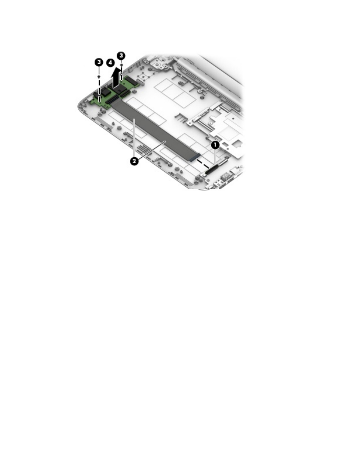
Remove the TouchPad board:
1. Turn the keyboard/top cover upside down with the front toward you.
2. Remove the three Phillips PM2.0×2.8 screws (1) that secure the TouchPad board bracket
and TouchPad board to the top cover.
3. Remove the three Phillips PM2.0×2.2 broad head screws (2) that secure the TouchPad board to
the top cover.
4. Remove the TouchPad board bracket (3).
50 Chapter 5 Removal and replacement procedures
Page 59

5. Remove the TouchPad board (4) and cable.
Reverse this procedure to install the TouchPad board.
Component replacement procedures 51
Page 60

Display assembly
NOTE: The display assembly is spared at the subcomponent level only. For more display assembly spare
part information, see the individual removal subsections and see Display assembly subcomponents
on page 19.
Before removing the display assembly, follow these steps:
1. Turn o the computer. If you are unsure whether the computer is o or in Hibernation, turn
the computer on, and then shut it down through the operating system.
2. Disconnect the power from the computer by unplugging the power cord from the computer.
3. Disconnect all external devices from the computer.
4. Remove the keyboard/top cover (see Keyboard/top cover on page 28).
5. Disconnect the battery (see Battery on page 36).
Remove the display assembly:
1. Remove the four Phillips PM2.4×4.6 screws (1) that secure the display assembly to the bottom cover.
2. Release the power connector cable (2) from the right hinge area.
3. Remove the display assembly (3).
4. If it is necessary to replace the display bezel or any of the display assembly subcomponents:
a. Flex the inside edges of the top edge (1), the left and right sides (2), and the bottom edge (3) of
the display bezel until the bezel disengages from the display back cover.
b. Remove the display bezel (4).
52 Chapter 5 Removal and replacement procedures
Page 61

5. If it is necessary to replace the display panel:
a. Remove the four Phillips PM2.0×3.3 screws that secure the display panel to the display back cover.
CAUTION: Before turning the display panel upside down, make sure the work surface is clear of
tools, screws, and any other foreign objects. Failure to follow this caution can result in damage to
the display panel.
b. Lift the top edge of the display panel (1) and swing it up and forward until it rests upside down in
front of the display back cover.
c. Release the adhesive strip (2) that secures the display panel cable connector to the display panel
and disconnect the display cable from the display panel.
Component replacement procedures 53
Page 62

d. Remove the display panel (3).
6. If it is necessary to replace the display hinges:
a. Remove the four Phillips PM2.5×3.2 broad head screws (1) that secure the display hinges to
the display back cover.
b. Remove the two Phillips PM2.0×2.9 broad head screws (2) that secure the display hinges to
the display back cover.
c. Remove the display hinges (3).
7. If it is necessary to replace the display panel cable:
54 Chapter 5 Removal and replacement procedures
Page 63

a. Disconnect the display panel cable (1) from the camera/microphone module.
b. Release the display panel cable from the retention clips (2) and routing channel built into the right
side of the display back cover.
c. Remove the display panel cable (3).
8. If it is necessary to replace the camera/microphone module:
a. Detach the camera/microphone module (1) from the display back cover. (The camera/microphone
module is attached to the display back cover with double-sided adhesive at two locations.)
b. Disconnect the camera/microphone module cable (2) from the camera/microphone module.
Component replacement procedures 55
Page 64

c. Remove the camera/microphone module (3).
9. If it is necessary to replace the WLAN antenna cables and transceivers:
a. Detach the WLAN antenna transceivers (1) from the display back cover. (The WLAN antenna
transceivers are attached to the display back cover with double-sided adhesive.)
b. Release the WLAN antenna cables from the clips (2) and routing channel built into the top and left
edges of the display back cover.
c. Remove the WLAN antenna cables and transceivers (3).
Reverse this procedure to reassemble install the display assembly.
56 Chapter 5 Removal and replacement procedures
Page 65

Base enclosure
The base enclosure remains after disassembling the computer.
Description Spare part number
For use on HP Stream Laptop PC models only
Aqua blue nish 902949-001
Innity purple nish (only models with Intel Celeron N400 or Intel Celeron N3XXX) L23671-001
Neon pink nish (only models with Intel Celeron N400) L23672-001
Snow white nish 910457-001
Smoke gray nish (only models with Intel Celeron N400) L32380-001
Violet purple nish (only models with Intel Celeron N3XXX) 902950-001
For use on HP Stream Laptop PC models with Intel Celeron N400 and HP Stream 11 Pro G3 Notebook
PC models only
Jack black nish 908300-001
For use on HP Stream 11 Pro G4 Education Edition Notebook PC models only L02780-001
Component replacement procedures 57
Page 66

6 Using Setup Utility (BIOS)
Setup Utility, or Basic Input/Output System (BIOS), controls communication between all the input and output
devices on the system (such as disk drives, display, keyboard, mouse, and printer). Setup Utility (BIOS)
includes settings for the types of devices installed, the startup sequence of the computer, and the amount of
system and extended memory.
NOTE: To start Setup Utility on convertible computers, your computer must be in notebook mode and you
must use the keyboard attached to your notebook.
Starting Setup Utility (BIOS)
CAUTION: Use extreme care when making changes in Setup Utility (BIOS). Errors can prevent the computer
from operating properly.
▲ Turn on or restart the computer, quickly press esc, and then press f10.
Updating Setup Utility (BIOS)
Updated versions of Setup Utility (BIOS) may be available on the HP website.
Most BIOS updates on the HP website are packaged in compressed les called SoftPaqs.
Some download packages contain a le named Readme.txt, which contains information regarding installing
and troubleshooting the le.
Determining the BIOS version
To decide whether you need to update Setup Utility (BIOS), rst determine the BIOS version on your computer.
To reveal the BIOS version information (also known as ROM date and System BIOS), use one of these options.
● HP Support Assistant
1. Type support in the taskbar search box, and then select the HP Support Assistant app.
– or –
Click the question mark icon in the taskbar.
2. Select My PC, and then select Specications.
● Setup Utility (BIOS)
1. Start Setup Utility (BIOS) (see Starting Setup Utility (BIOS) on page 58).
2. Select Main, select System Information, and then make note of the BIOS version.
3. Select Exit, select No, and then follow the on-screen instructions.
To check for later BIOS versions, see Downloading a BIOS update on page 59.
58 Chapter 6 Using Setup Utility (BIOS)
Page 67

Downloading a BIOS update
CAUTION: To reduce the risk of damage to the computer or an unsuccessful installation, download and
install a BIOS update only when the computer is connected to reliable external power using the AC adapter. Do
not download or install a BIOS update while the computer is running on battery power, docked in an optional
docking device, or connected to an optional power source. During the download and installation, follow these
instructions:
● Do not disconnect power from the computer by unplugging the power cord from the AC outlet.
● Do not shut down the computer or initiate Sleep.
● Do not insert, remove, connect, or disconnect any device, cable, or cord.
NOTE: If your computer is connected to a network, consult the network administrator before installing any
software updates, especially system BIOS updates.
1. Type support in the taskbar search box, and then select the HP Support Assistant app.
– or –
Click the question mark icon in the taskbar.
2. Click Updates, and then click Check for updates and messages.
3. Follow the on-screen instructions.
4. At the download area, follow these steps:
a. Identify the most recent BIOS update and compare it to the BIOS version currently installed on your
computer. If the update is more recent than your BIOS version, make a note of the date, name, or
other identier. You may need this information to locate the update later, after it has been
downloaded to your hard drive.
b. Follow the on-screen instructions to download your selection to the hard drive.
Make a note of the path to the location on your hard drive where the BIOS update is downloaded.
You will need to access this path when you are ready to install the update.
BIOS installation procedures vary. Follow any instructions that appear on the screen after the download is
complete. If no instructions appear, follow these steps:
1. Type file in the taskbar search box, and then select File Explorer.
2. Click your hard drive designation. The hard drive designation is typically Local Disk (C:).
3. Using the hard drive path you recorded earlier, open the folder that contains the update.
4. Double-click the le that has an .exe extension (for example, lename.exe).
The BIOS installation begins.
5. Complete the installation by following the on-screen instructions.
NOTE: After a message on the screen reports a successful installation, you can delete the downloaded le
from your hard drive.
Updating Setup Utility (BIOS) 59
Page 68

7 Using HP PC Hardware Diagnostics
Using HP PC Hardware Diagnostics Windows
HP PC Hardware Diagnostics Windows is a Windows-based utility that allows you to run diagnostic tests to
determine whether the computer hardware is functioning properly. The tool runs within the Windows
operating system in order to diagnose hardware failures.
If HP PC Hardware Diagnostics Windows is not installed on your computer, rst you must download and install
it. To download HP PC Hardware Diagnostics Windows, see Downloading HP PC Hardware Diagnostics
Windows on page 60.
After HP PC Hardware Diagnostics Windows is installed, follow these steps to access it from HP Help and
Support or HP Support Assistant.
1. To access HP PC Hardware Diagnostics Windows from HP Help and Support:
a. Select the Start button, and then select HP Help and Support.
b. Right-click HP PC Hardware Diagnostics Windows, select More, and then select Run as
administrator.
– or –
To access HP PC Hardware Diagnostics Windows from HP Support Assistant:
a. Type support in the taskbar search box, and then select the HP Support Assistant app.
– or –
Select the question mark icon in the taskbar.
b. Select Troubleshooting and xes.
c. Select Diagnostics, and then select HP PC Hardware Diagnostics Windows.
2. When the tool opens, select the type of diagnostic test you want to run, and then follow the on-screen
instructions.
NOTE: If you need to stop a diagnostic test at any time, select Cancel.
3. When HP PC Hardware Diagnostics Windows detects a failure that requires hardware replacement, a 24-
digit Failure ID code is generated. For assistance in correcting the problem, contact support, and then
provide the Failure ID code.
Downloading HP PC Hardware Diagnostics Windows
● The HP PC Hardware Diagnostics Windows download instructions are provided in English only.
● You must use a Windows computer to download this tool because only .exe les are provided.
60 Chapter 7 Using HP PC Hardware Diagnostics
Page 69

Downloading the latest HP PC Hardware Diagnostics Windows version
To download HP PC Hardware Diagnostics Windows, follow these steps:
1. Go to http://www.hp.com/go/techcenter/pcdiags. The HP PC Diagnostics home page is displayed.
2. In the HP PC Hardware Diagnostics section, select Download, and then select the installation location:
To run the tool on your computer, download it to the computer desktop.
– or –
To run the tool from a USB ash drive, download it to a USB ash drive.
3. Select Run.
Downloading HP Hardware Diagnostics Windows by product name or number (select products only)
NOTE: For some products, it may be necessary to download the software to a USB ash drive by using the
product name or number.
To download HP PC Hardware Diagnostics Windows by product name or number (select products only), follow
these steps:
1. Go to http://www.hp.com/support.
2. Select Get software and drivers, and then enter the product name or number.
3. In the HP PC Hardware Diagnostics section, select Download, and then select the installation location:
To run the tool on your computer, download it to the computer desktop.
– or –
To run the tool from a USB ash drive, download it to a USB ash drive.
4. Select Run.
Installing HP PC Hardware Diagnostics Windows
To install HP PC Hardware Diagnostics Windows, follow these steps:
▲ Navigate to the folder on your computer or the ash drive where the .exe le was downloaded, double-
click the .exe le, and then follow the on-screen instructions.
Using HP PC Hardware Diagnostics UEFI
HP PC Hardware Diagnostics UEFI (Unied Extensible Firmware Interface) allows you to run diagnostic tests to
determine whether the computer hardware is functioning properly. The tool runs outside the operating
system so that it can isolate hardware failures from issues that are caused by the operating system or other
software components.
If your PC will not boot into Windows, you can use HP PC Hardware Diagnostics UEFI to diagnose hardware
issues.
When HP PC Hardware Diagnostics UEFI detects a failure that requires hardware replacement, a 24-digit
Failure ID code is generated. For assistance in correcting the problem, contact support, and provide the Failure
ID code.
NOTE: To start diagnostics on a convertible computer, your computer must be in notebook mode, and you
must use the attached keyboard.
Using HP PC Hardware Diagnostics UEFI 61
Page 70

NOTE: If you need to stop a diagnostic test, press esc.
Starting HP PC Hardware Diagnostics UEFI
To start HP PC Hardware Diagnostics UEFI, follow these steps:
1. Turn on or restart the computer, and quickly press esc.
2. Press f2.
The BIOS searches three places for the diagnostic tools, in the following order:
a. Connected USB ash drive
NOTE: To download the HP PC Hardware Diagnostics UEFI tool to a USB ash drive, see
Downloading the latest HP PC Hardware Diagnostics UEFI version on page 62.
b. Hard drive
c. BIOS
3. When the diagnostic tool opens, select the type of diagnostic test you want to run, and then follow the
on-screen instructions.
Downloading HP PC Hardware Diagnostics UEFI to a USB ash drive
Downloading HP PC Hardware Diagnostics UEFI to a USB ash drive can be useful in the following situations:
● HP PC Hardware Diagnostics UEFI is not included in the preinstall image.
● HP PC Hardware Diagnostics UEFI is not included in the HP Tool partition.
● The hard drive is damaged.
NOTE: The HP PC Hardware Diagnostics UEFI download instructions are provided in English only, and you
must use a Windows computer to download and create the HP UEFI support environment because only .exe
les are provided.
Downloading the latest HP PC Hardware Diagnostics UEFI version
To download the latest HP PC Hardware Diagnostics UEFI version to a USB ash drive:
1. Go to http://www.hp.com/go/techcenter/pcdiags. The HP PC Diagnostics home page is displayed.
2. In the HP PC Hardware Diagnostics UEFI section, select Download UEFI Diagnostics, and then select
Run.
Downloading HP PC Hardware Diagnostics UEFI by product name or number (select products only)
NOTE: For some products, it may be necessary to download the software to a USB ash drive by using the
product name or number.
To download HP PC Hardware Diagnostics UEFI by product name or number (select products only) to a USB
ash drive:
62 Chapter 7 Using HP PC Hardware Diagnostics
Page 71

1. Go to http://www.hp.com/support.
2. Enter the product name or number, select your computer, and then select your operating system.
3. In the Diagnostics section, follow the on-screen instructions to select and download the specic UEFI
Diagnostics version for your computer.
Using Remote HP PC Hardware Diagnostics UEFI settings (select products only)
Remote HP PC Hardware Diagnostics UEFI is a rmware (BIOS) feature that downloads HP PC Hardware
Diagnostics UEFI to your computer. It can then execute the diagnostics on your computer, and it may upload
results to a precongured server. For more information on Remote HP PC Hardware Diagnostics UEFI, go to
http://www.hp.com/go/techcenter/pcdiags, and then select Find out more.
Downloading Remote HP PC Hardware Diagnostics UEFI
NOTE: HP Remote PC Hardware Diagnostics UEFI is also available as a Softpaq that can be downloaded to a
server.
Downloading the latest Remote HP PC Hardware Diagnostics UEFI version
To download the latest Remote HP PC Hardware Diagnostics UEFI version, follow these steps:
1. Go to http://www.hp.com/go/techcenter/pcdiags. The HP PC Diagnostics home page is displayed.
2. In the HP PC Hardware Diagnostics UEFI section, select Download Remote Diagnostics, and then select
Run.
Downloading Remote HP PC Hardware Diagnostics UEFI by product name or number
NOTE: For some products, it may be necessary to download the software by using the product name or
number.
To download HP Remote PC Hardware Diagnostics UEFI by product name or number, follow these steps:
1. Go to http://www.hp.com/support.
2. Select Get software and drivers, enter the product name or number, select your computer, and then
select your operating system.
3. In the Diagnostics section, follow the on-screen instructions to select and download the Remote UEFI
version for the product.
Customizing Remote HP PC Hardware Diagnostics UEFI settings
Using the Remote HP PC Hardware Diagnostics setting in Computer Setup (BIOS), you can perform the
following customizations:
● Set a schedule for running diagnostics unattended. You can also start diagnostics immediately in
interactive mode by selecting Execute Remote HP PC Hardware Diagnostics.
● Set the location for downloading the diagnostic tools. This feature provides access to the tools from the
HP website or from a server that has been precongured for use. Your computer does not require the
traditional local storage (such as a disk drive or USB ash drive) to run remote diagnostics.
Using Remote HP PC Hardware Diagnostics UEFI settings (select products only) 63
Page 72

● Set a location for storing the test results. You can also set the user name and password settings used for
uploads.
● Display status information about the diagnostics run previously.
To customize Remote HP PC Hardware Diagnostics UEFI settings, follow these steps:
1. Turn on or restart the computer, and when the HP logo appears, press f10 to enter Computer Setup.
2. Select Advanced, and then select Settings.
3. Make your customization selections.
4. Select Main, and then Save Changes and Exit to save your settings.
Your changes take eect when the computer restarts.
64 Chapter 7 Using HP PC Hardware Diagnostics
Page 73

8 Specications
Metric U.S.
Computer dimensions
Width 30.0 cm 11.8 in
Depth (HP Stream Laptop PC models) 20.6 cm 8.1 in
(HP Stream 11 Pro G4 Education Edition Notebook PC) 20.8 cm 8.2 in
Height 1.8 cm 0.7 in
Weight (HP Stream Laptop PC models) 1.2 kg 2.6 lbs
(HP Stream 11 Pro G4 Education Edition Notebook PC) 1.3 kg 2.8 lbs
Input power Rating
Operating voltage and current 19.5 V dc @ 2.31 A – 45 W
Temperature
Operating 5°C to 35°C 41°F to 95°F
19.5 V dc @ 3.33 A – 65 W
Nonoperating ‑20°C to 60°C ‑4°F to 140°F
Relative humidity (noncondensing)
Operating 10% to 90%
Nonoperating 5% to 95%
Maximum altitude (unpressurized)
Operating ‑15 m to 3,048 m ‑50 ft to 10,000 ft
Nonoperating ‑15 m to 12,192 m ‑50 ft to 40,000 ft
NOTE: Applicable product safety standards specify thermal limits for plastic surfaces. The device operates well within this range of
temperatures.
65
Page 74

9 Backing up, restoring, and recovering
This chapter provides information about the following processes, which are standard procedure for most
products:
● Backing up your personal information—You can use Windows tools to back up your personal
information (see Using Windows tools on page 66).
● Creating a restore point—You can use Windows tools to create a restore point (see Using Windows
tools on page 66).
● Creating recovery media (select products only)—You can use HP Recovery Manager or HP Cloud
Recovery Download Tool (select products only) to create recovery media (see Creating HP Recovery
media (select products only) on page 66).
● Restoring and recovery—Windows oers several options for restoring from backup, refreshing the
computer, and resetting the computer to its original state (see Using Windows tools on page 66).
● Removing the Recovery Partition—To remove the Recovery partition to reclaim hard drive space
(select products only), select the Remove Recovery Partition option of HP Recovery Manager. For more
information, see Removing the HP Recovery partition (select products only) on page 70.
Using Windows tools
IMPORTANT: Windows is the only option that allows you to back up your personal information. Schedule
regular backups to avoid information loss.
You can use Windows tools to back up personal information and create system restore points and recovery
media, allowing you to restore from backup, refresh the computer, and reset the computer to its original
state.
NOTE: If computer storage is 32 GB or less, Microsoft System Restore is disabled by default.
For more information and steps, see the Get Help app.
▲ Select the Start button, and then select the Get Help app.
NOTE: You must be connected to the Internet to access the Get Help app.
Creating HP Recovery media (select products only)
After you have successfully set up the computer, use HP Recovery Manager to create a backup of the HP
Recovery partition on the computer. This backup is called HP Recovery media. In cases where the hard drive is
corrupted or has been replaced, the HP Recovery media can be used to reinstall the original operating system.
To check for the presence of the Recovery partition in addition to the Windows partition, right-click the Start
button, select File Explorer, and then select This PC.
NOTE: If your computer does not list the Recovery partition in addition to the Windows partition, contact
support to obtain recovery discs. Go to http://www.hp.com/support, select your country or region, and then
follow the on-screen instructions.
66 Chapter 9 Backing up, restoring, and recovering
Page 75

On select products, you can use the HP Cloud Recovery Download Tool to create HP Recovery media on a
bootable USB ash drive. For more information, see Using the HP Cloud Recovery Download Tool to create
recovery media on page 68.
Using HP Recovery Manager to create recovery media
NOTE: If you cannot create recovery media yourself, contact support to obtain recovery discs. Go to
http://www.hp.com/support, select your country or region, and then follow the on-screen instructions.
Before you begin
Before you begin, note the following:
● Only one set of recovery media can be created. Handle these recovery tools carefully, and keep them in a
safe place.
● HP Recovery Manager examines the computer and determines the required media storage capacity.
● To create recovery media, use one of the following options:
NOTE: If the computer does not have a recovery partition, HP Recovery Manager displays the Windows
Create a Recovery Drive feature. Follow the on-screen instructions to create a recovery image on a blank
USB ash drive or hard drive.
– If your computer has an optical drive with DVD writer capability, be sure to use only high-quality
blank DVD-R, DVD+R, DVD-R DL, or DVD+R DL discs. Do not use rewritable discs such as CD±RW,
DVD±RW, double-layer DVD±RW, or BD-RE (rewritable Blu-ray) discs, which are not compatible
with HP Recovery Manager software.
– If your computer does not include an integrated optical drive with DVD writer capability, you can
use an external optical drive (purchased separately) to create recovery discs, as described above. If
an external optical drive is used, you must connect it directly to a USB port on the computer. It
cannot be connected to a USB port on an external device, such as a USB hub.
– To create a recovery ash drive, use a high-quality blank USB ash drive.
● Be sure that the computer is connected to AC power before you begin creating the recovery media.
● The creation process can take an hour or more. Do not interrupt this process.
● If necessary, you can exit the program before you have nished creating all of the recovery media. HP
Recovery Manager will nish the current DVD or ash drive. The next time you start HP Recovery
Manager, you will be prompted to continue.
Creating the recovery media
To create HP Recovery media using HP Recovery Manager:
IMPORTANT: For a tablet with a detachable keyboard, connect the tablet to the keyboard base before
beginning these steps.
1. Type recovery in the taskbar search box, and then select HP Recovery Manager.
2. Select Create recovery media, and then follow the on-screen instructions.
If you need to recover the system, see Recovering using HP Recovery Manager on page 68.
Creating HP Recovery media (select products only) 67
Page 76

Using the HP Cloud Recovery Download Tool to create recovery media
To create HP Recovery media using the HP Cloud Recovery Download Tool:
1. Go to http://www.hp.com/support.
2. Select Software and Drivers, and then follow the on-screen instructions.
Restoring and recovery
Restoring and recovery can be performed using one or more of the following options: Windows tools, HP
Recovery Manager, or the HP Recovery partition.
IMPORTANT: Not all methods are available on all products.
Restoring, resetting, and refreshing using Windows tools
Windows oers several options for restoring, resetting, and refreshing the computer. For details, see Using
Windows tools on page 66.
Restoring using HP Recovery Manager and the HP Recovery partition
You can use HP Recovery Manager and the HP Recovery partition (select products only) to restore the
computer to the original factory state:
● Resolving problems with preinstalled applications or drivers—To correct a problem with a
preinstalled application or driver:
1. Type recovery in the taskbar search box, and then select HP Recovery Manager.
2. Select Reinstall drivers and/or applications, and then follow the on-screen instructions.
● Using System Recovery—To recover the Windows partition to original factory content, select the
System Recovery option from the HP Recovery partition (select products only) or use the HP Recovery
media. For more information, see Recovering using HP Recovery Manager on page 68. If you have not
already created recovery media, see Creating HP Recovery media (select products only) on page 66.
● Using Factory Reset (select products only)—Restores the computer to its original factory state by
deleting all information from the hard drive and recreating the partitions and then reinstalling the
operating system and the software that was installed at the factory (select products only). To use the
Factory Reset option, you must use HP Recovery media. If you have not already created recovery media,
see Creating HP Recovery media (select products only) on page 66.
NOTE: If you have replaced the hard drive in the computer, you can use the Factory Reset option to
install the operating system and the software that was installed at the factory.
Recovering using HP Recovery Manager
You can use HP Recovery Manager software to recover the computer to its original factory state by using the
HP Recovery media that you either created or that you obtained from HP, or by using the HP Recovery
partition (select products only).
If you have not already created HP Recovery media, see Creating HP Recovery media (select products only)
on page 66.
IMPORTANT: HP Recovery Manager does not automatically provide backups of your personal data. Before
beginning recovery, back up any personal data that you want to retain. See Using Windows tools on page 66.
68 Chapter 9 Backing up, restoring, and recovering
Page 77

IMPORTANT: Recovery through HP Recovery Manager should be used as a nal attempt to correct computer
issues.
NOTE: When you start the recovery process, only the options available for your computer are displayed.
Before you begin, note the following:
● HP Recovery Manager recovers only software that was installed at the factory. For software not provided
with this computer, you must either download the software from the manufacturer's website or reinstall
the software from the media provided by the manufacturer.
● If the computer hard drive fails, HP Recovery media must be used. This media is created using HP
Recovery Manager. See
● If your computer does not allow the creation of HP Recovery media or if the HP Recovery media does not
work, contact support to obtain recovery media. Go to http://www.hp.com/support, select your country
or region, and then follow the on-screen instructions.
Creating HP Recovery media (select products only) on page 66.
Recovering using the HP Recovery partition (select products only)
The HP Recovery partition allows you to perform a system recovery without recovery discs or a recovery USB
ash drive. This type of recovery can be used only if the hard drive is still working.
The HP Recovery partition (select products only) allows System Recovery only.
To start HP Recovery Manager from the HP Recovery partition:
IMPORTANT: For a tablet with a detachable keyboard, connect the tablet to the keyboard base before
beginning these steps (select products only).
1. Type recovery in the taskbar search box, select HP Recovery Manager, and then select Windows
Recovery Environment
‒ or –
For computers or tablets with keyboards attached:
▲ Press f11 while the computer boots, or press and hold f11 as you press the power button.
For tablets without keyboards:
▲ Turn on or restart the tablet, quickly hold down the volume up button, and then select f11.
2. Select Troubleshoot from the boot options menu.
3. Select Recovery Manager, and then follow the on-screen instructions.
NOTE: If your computer does not automatically restart in HP Recovery Manager, change the computer
boot order, and then follow the on-screen instructions. See Changing the computer boot order
on page 70.
.
Recovering using HP Recovery media
If your computer does not have an HP Recovery partition or if the hard drive is not working properly, you can
use HP Recovery media to recover the original operating system and software programs that were installed at
the factory.
▲ Insert the HP Recovery media, and then restart the computer.
Restoring and recovery 69
Page 78

NOTE: If your computer does not automatically restart in HP Recovery Manager, change the computer
boot order, and then follow the on-screen instructions. See Changing the computer boot order
on page 70.
Changing the computer boot order
If your computer does not restart in HP Recovery Manager, you can change the computer boot order. This is
the order of devices listed in BIOS where the computer looks for startup information. You can change the
selection to an optical drive or a USB ash drive, depending on the location of your HP Recovery media.
To change the boot order:
IMPORTANT: For a tablet with a detachable keyboard, connect the tablet to the keyboard base before
beginning these steps.
1. Insert the HP Recovery media.
2. Access the system Startup menu.
For computers or tablets with keyboards attached:
▲ Turn on or restart the computer or tablet, quickly press esc, and then press f9 for boot options.
For tablets without keyboards:
▲ Turn on or restart the tablet, quickly hold down the volume up button, and then select f9.
‒ or –
Turn on or restart the tablet, quickly hold down the volume down button, and then select f9.
3. Select the optical drive or USB ash drive from which you want to boot, and then follow the on-screen
instructions.
Removing the HP Recovery partition (select products only)
HP Recovery Manager software allows you to remove the HP Recovery partition (select products only) to free
up hard drive space.
IMPORTANT: After you remove the HP Recovery partition, you will not be able to perform System Recovery
or create HP Recovery media. Before removing the Recovery partition, create HP Recovery media. See
Creating HP Recovery media (select products only) on page 66.
Follow these steps to remove the HP Recovery partition:
1. Type recovery in the taskbar search box, and then select HP Recovery Manager.
2. Select Remove Recovery Partition, and then follow the on-screen instructions.
70 Chapter 9 Backing up, restoring, and recovering
Page 79

10 Power cord set requirements
The wide-range input feature of the computer permits it to operate from any line voltage from 100 to 120 V
ac, or from 220 to 240 V ac.
The 3-conductor power cord set included with the computer meets the requirements for use in the country or
region where the equipment is purchased.
Power cord sets for use in other countries or regions must meet the requirements of the country and region
where the computer is used.
Requirements for all countries
The following requirements are applicable to all countries and regions:
● The length of the power cord set must be at least 1.0 m (3.3 ft) and no more than 2.0 m (6.5 ft).
● All power cord sets must be approved by an acceptable accredited agency responsible for evaluation in
the country or region where the power cord set will be used.
● The power cord sets must have a minimum current capacity of 10 A and a nominal voltage rating of 125
or 250 V ac, as required by the power system of each country or region.
● The appliance coupler must meet the mechanical conguration of an EN 60 320/IEC 320 Standard Sheet
C13 connector for mating with the appliance inlet on the back of the computer.
Requirements for all countries 71
Page 80

Requirements for specic countries and regions
Country/region Accredited agency Applicable note number
Argentina IRAM 1
Australia SAA 1
Austria OVE 1
Belgium CEBEC 1
Brazil ABNT 1
Canada CSA 2
Chile IMQ 1
Denmark DEMKO 1
Finland FIMKO 1
France UTE 1
Germany VDE 1
India ISI 1
Israel SII 1
Italy IMQ 1
Japan JIS 3
The Netherlands KEMA 1
New Zealand SANZ 1
Norway NEMKO 1
The People's Republic of China CCC 4
Saudi Arabia SASO 7
Singapore PSB 1
South Africa SABS 1
South Korea KTL 5
Sweden SEMKO 1
Switzerland SEV 1
Taiwan BSMI 6
Thailand TISI 1
The United Kingdom ASTA 1
The United States UL 2
1. The exible cord must be Type HO5VV-F, 3-conductor, 0.75 mm² conductor size. Power cord set ttings (appliance coupler and
wall plug) must bear the certication mark of the agency responsible for evaluation in the country or region where it will be used.
2. The exible cord must be Type SVT/SJT or equivalent, No. 18 AWG, 3-conductor. The wall plug must be a two-pole grounding type
with a NEMA 5-15P (15 A, 125 V ac) or NEMA 6-15P (15 A, 250 V ac) conguration. CSA or C-UL mark. UL le number must be on
each element.
72 Chapter 10 Power cord set requirements
Page 81

Country/region Accredited agency Applicable note number
3. The appliance coupler, exible cord, and wall plug must bear a “T” mark and registration number in accordance with the Japanese
Dentori Law. The exible cord must be Type VCR, 3-conductor, 0.75 mm² or 1.25 mm² conductor size. The wall plug must be a
two-pole grounding type with a Japanese Industrial Standard c/o (7 A, 125 V ac) conguration.
4. The exible cord must be Type REV, 3-conductor, 0.75 mm² conductor size. Power cord set ttings (appliance coupler and wall
plug) must bear the CCC certication mark.
5. The exible cord must be Type H05VV-F 3-conductor, 0.75 mm² conductor size. KTL logo and individual approval number must
be on each element. Corset approval number and logo must be printed on a ag label.
6. The exible cord must be Type HVCTF 3-conductor, 1.25 mm² conductor size. Power cord set ttings (appliance coupler, cable,
and wall plug) must bear the BSMI certication mark.
7. For 127 V ac, the exible cord must be Type SVT or SJT 3-conductor, 18 AWG, with plug NEMA 5-15P (15 A, 125 V ac), with UL and
CSA or C-UL marks. For 240 V ac, the exible cord must be Type H05VV-F 3-conductor, 0.75 mm² or 1.00 mm2 conductor size,
with plug BS 1363/A with BSI or ASTA marks.
Requirements for specic countries and regions 73
Page 82

11 Recycling
When a non-rechargeable or rechargeable battery has reached the end of its useful life, do not dispose of
the battery in general household waste. Follow the local laws and regulations in your area for battery
disposal.
HP encourages customers to recycle used electronic hardware, HP original print cartridges, and rechargeable
batteries. For more information about recycling programs, see the HP Web site at
http://www.hp.com/recycle.
74 Chapter 11 Recycling
Page 83

Index
A
AC adapter, spare part numbers 20
AC adapter/battery light 12
antenna
location 8
removal 56
spare part numbers 20
audio, product description 2
audio-in jack 11
audio-out jack 11
B
backup, creating 66
backups 66
base enclosure
removal 57
base enclosure, spare part
numbers 17
battery
removal 36
spare part number 17, 36
BIOS
determining version 58
downloading an update 59
starting the Setup Utility 58
updating 58
boot order, changing 70
bottom components 13
button components 9
buttons
power 9
TouchPad 10
C
cables, service considerations 22
camera light 8
case, spare part number 21
chipset, product description 1
components
bottom 13
buttons 9
display 8
left side 11
right side 12
TouchPad 10
computer major components 16
connector board
removal 46
spare part numbers 17, 46
connector board cable, spare part
number 17, 46
connectors
power 12
service considerations 22
D
display assembly
removal 52
subcomponents 19
display bezel
removal 52
spare part numbers 19
display components 8
display enclosure, spare part
number 20
Display Hinge Kit, spare part
number 20
display panel
product description 1
removal 53
spare part numbers 20
display panel cable
removal 54
spare part number 20
drives
precautions 23
preventing damage 23
E
electrostatic discharge 24
equipment guidelines 26
external media cards, product
description 4
F
feet
removal 27
spare part numbers 27
G
graphics, product description 1
grounding guidelines 24
guidelines
equipment 26
grounding 24
packaging 25
transporting 25
workstation 25
H
HDMI port 12
HDMI to VGA adapter, spare part
number 21
headphone jack 11
headset, spare part number 21
heat sink
removal 40
spare part number 17, 40
hinge
removal 54
spare part number 20
HP PC Hardware Diagnostics UEFI
downloading 62
starting 62
using 61
HP PC Hardware Diagnostics Windows
downloading 60
installing 61
using 60
HP Recovery Manager
correcting boot problems 70
starting 69
HP Recovery media
recovery 69
using 67
HP Recovery partition
recovery 69
removing 70
J
jacks
audio-in 11
audio-out 11
Index 75
Page 84

headphone 11
microphone 11
K
keyboard/top cover
removal 28
spare part numbers 17, 28
L
left-side components 11
lights
AC adapter/battery 12
camera 8
power 11
M
memory card reader 12
memory, product description 2
microphone
location 8
product description 2
microphone jack 11
minimized image recovery 69
minimized image, creating 68
model name 1
mouse, spare part number 21
O
operating system, product
description 4
optical drive, spare part number 21
original system recovery 68
P
packaging guidelines 25
plastic parts, service
considerations 22
ports
HDMI 12
product description 3
USB 2.0 11
USB 3.0 12
power button 9
power button board
removal 49
spare part number 17, 49
power button board cable, spare part
number 17, 49
power connector 12
power connector cable
removal 48
spare part number 17, 48
power cord
requirements for all countries
71
requirements for specic
countries and regions 72
set requirements 71
spare part numbers 21
power cord, spare part number 21
power light 11
power requirements, product
description 4
processor, product description 1
product description
audio 2
chipset 1
display panel 1
external media cards 4
graphics 1
memory 2
microphone 2
operating system 4
ports 3
power requirements 4
processors 1
product name 1
serviceability 7
storage 2
video 2
wireless 3
product name 1
R
recovery 66
discs 67, 69
HP Recovery Manager 68
HP Recovery partition 68
media 69
starting 69
supported discs 67
system 68
USB ash drive 69
using HP Recovery media 67
recovery media
creating using HP Cloud Recovery
Download Tool 68
creating using HP Recovery
Manager 67
creating using Windows tools 66
discs 67
HP Recovery partition 66
USB ash drive 67
using 67
recovery partition, removing 70
Remote HP PC Hardware Diagnostics
UEFI settings
customizing 63
using 63
removal/replacement procedures
27
restoring 66
right-side components 12
RTC battery
removal 34
spare part number 17, 34
Rubber Kit, spare part numbers 18
S
Screw Kit, spare part number 21
security cable slot 11
service considerations
cables 22
connectors 22
plastic parts 22
serviceability, product description 7
slots
security cable slot 11
speakers
location 13
removal 33
spare part number 17, 33
storage, product description 2
supported discs, recovery 67
system board
removal 42
spare part numbers 17, 42
system recovery 68
system restore point, creating 66
T
tools required 22
TouchPad board
removal 50
spare part numbers 17, 50
TouchPad board cable, spare part
number 17, 50
TouchPad buttons 10
TouchPad components 10
76 Index
Page 85

TouchPad zone 10
transporting guidelines 25
U
USB 2.0 port 11
USB 3.0 port 12
USB to Gigabit RJ45 adapter, spare
part number 21
V
video, product description 2
W
webcam 8
webcam/microphone module
removal 55
spare part number 20
Windows
backup 66
recovery media 66
system restore point 66
Windows tools, using 66
wireless antenna
location 8
removal 56
spare part numbers 20
wireless, product description 3
WLAN antenna
location 8
removal 56
spare part number 20
WLAN module
removal 37
spare part numbers 17, 37
workstation guidelines 25
Index 77
 Loading...