

Page 1
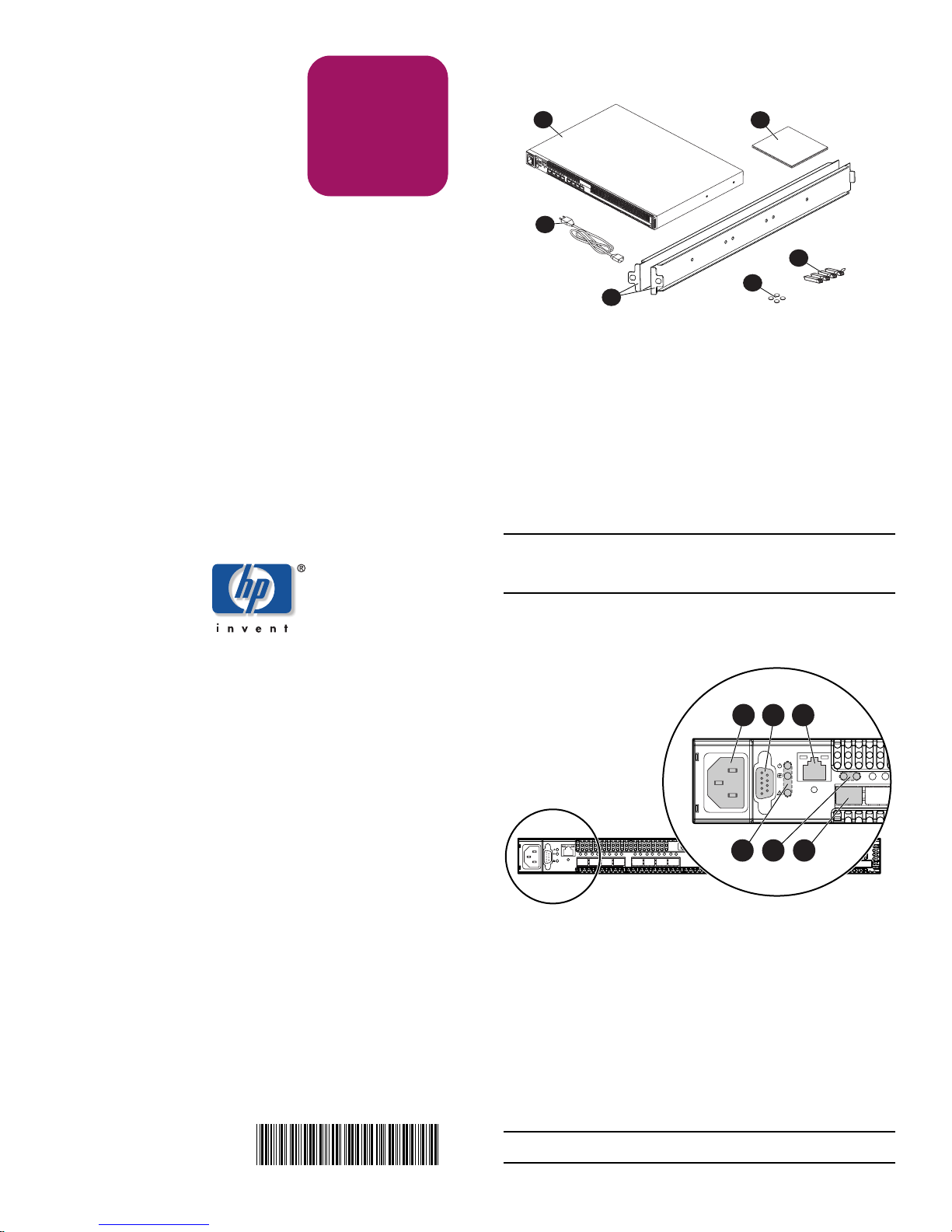
Step 1: Verify package contents
Installation
Instructions
HP StorageWorks
2/8q Fibre Channel
Switch
Quick Start
For additional instructions, refer to the
2/8q FC Switch Installation Guide and
the MSA1000 Small Business SAN Kit
Installation poster.
1
3
4
1 2/8q FC Switch
2 Quick Start Installation Instructions
(this document)
3 Power cable
(approved for use in the United States)
4 Mounting adapter brackets and screws
5 Rubber feet
6 Small Form Factor Pluggable (SFP) transceivers
Note: Additional power cables approved for use in countries other
than the United States may be included in the shipping carton. Use
the cable appropriate for your installation.
2
6
5
© Copyright 2004 Hewlett-Packard Development Company, L.P.
Hewlett-Packard Company makes no warranty of any kind with regard to
this material, including, but not limited to, the implied warranties of
merchantability and fitness for a particular purpose. Hewlett-Packard shall
not be liable for errors contained herein or for incidental or consequential
damages in connection with the furnishing, performance, or use of this
material.
This document contains proprietary information, which is protected by
copyright. No part of this document may be photocopied, reproduced,
or translated into another language without the prior written consent of
Hewlett-Packard. The information contained in this document is subject to
change without notice.
Product names mentioned herein may be trademarks of their respective
companies as reflected by an associated footnote.
Hewlett-Packard Company shall not be liable for technical or editorial
errors or omissions contained herein. The information is provided “as is”
without warranty of any kind and is subject to change without notice. The
warranties for Hewlett-Packard Company products are set forth in the
express limited warranty statements for such products. Nothing herein
should be construed as constituting an additional warranty.
Printed in the U.S.A.
HP StorageWorks 2/8q FC Switch Quick Start
Installation Instructions
First Edition (November 2004)
Part Number: A7450-96001
Step 2: Identify switch features
1 2 3
4 5 6
1 Power receptacle
2 Serial port
3 Ethernet port
4 Chassis LEDs
(Input Power, Heartbeat, and System Fault)
5 Fibre Channel port LEDs
(Port Logged-In and Activity)
6 Fibre Channel port 0
A7450- 96001
Note: Do not connect power to the switch until instructed in step 5.
Page 2
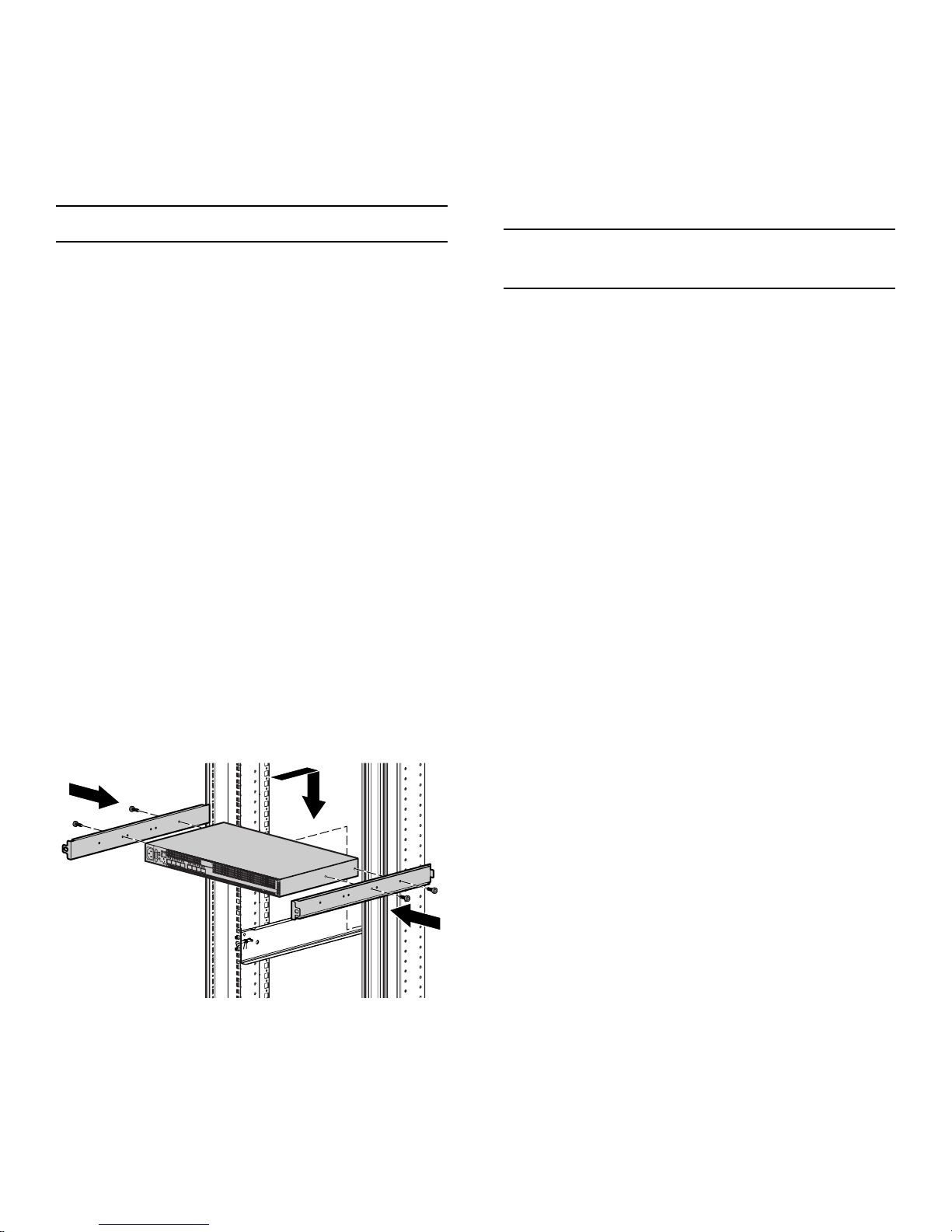
Step 3: Mount the switch
Step 4: Install the SFPs
For a surface mount:
Obtain the rubber feet from the switch carton and attach the
feet to the bottom of the switch. Then, place the switch on a
stable work surface.
For a rack mount:
Note: This switch is mounted from the rear of the rack.
1. Obtain the 2U rack template and 2U rail kit from the
MSA1000 SAN Kit carton, and the switch mounting
adapter brackets and screws from the switch carton.
2. Use the template to mark the holes on the front and back of
the rack, to indicate the location for the rails.
3. From the rear of the rack, install the rails by inserting the
left rail (marked L) into the inside-left rear of the rack, until
the pins extend through the holes marked in step 2 and the
scissor-type locking latch engages. Then, extend the other
end of the rail toward the inside front of the rack until the
pins extend through the marked holes. Loosen the locking
nut on the retaining bracket and slide the bracket to the
farthest position near the front of rack. Repeat these steps to
install the other rail.
4. Fasten the mounting adapter brackets to the switch, with
the port side of the switch facing the flanges of the adapter
brackets. Position the brackets so that the switch is set back
approximately 3 inches from the flanges.
5. From the rear of the rack, slide the switch assembly onto
the previously installed rails, until the flanges of the
mounting brackets are flush with the rear uprights of the
rack.
6. Secure the switch to the rack by securing the provided
screws through the flanges to the rear of the rack, and then,
from the front of the rack, slide the retaining brackets on
the rail towards the switch, until they engage the switch.
Then tighten the thumbscrews on the retaining bracket.
1. Obtain the SFPs.
Four SFPs are included in the switch shipping carton;
additional SFPs may be purchased separately.
2. Insert an SFP into a Fibre Channel port.
Push the SFP into the port with gentle pressure until the
SFP snaps into place.
Note: An SFP fits only one way in the Fibre Channel port. If the SFP
does not install under gentle pressure, pull it out of the port, turn it
over, and re-insert it.
Step 5: Connect the cables
1. Connect a Fibre Channel cable between each SFP installed
in the switch and its corresponding device.
2. Attach the power cable between the switch and the power
source.
— Verify that the Input Power LED (green) is illuminated.
— Wait a few minutes for the self test to complete.
— Verify that the Heartbeat LED is blinking (once per
second) and the System Fault LED (amber) is NOT
illuminated.
Physical installation of your new switch is complete.
Step 6: Configure the switch
The 2/8q FC Switch, the HBA in the server, and the storage in
the MSA are configured using tools provided in the MSA1000
Small Business SAN Kit carton.
Obtain the MSA1000 Small Business SAN Kit Installation
Instructions from the MSA1000 SAN Kit carton, and follow
the instructions on the poster to prepare and configure the
devices.
For additional information about your 2/8q FC Switch, refer to
the switch documents provided on the MSA1000 SAN Kit
Documentation CD, including the Installation Guide,
Management User Guide, Release Notes, and Readme
information.
Page 2
 Loading...