

Page 1

user’s guide
hp StorageWorks
disk system 2300
Edition E0902
Page 2

Notice
© Hewlett-Packard Company, 2002. All rights
reserved.
A6490-96014
Hewlett-Packard Company makes no warranty of
any kind with regard to this material, including, but
not limited to, the implied warranties of
merchantability and fitness for a particular purpose.
Hewlett-Packard shall not be liable for errors
contained herein or for incidental or consequential
damages in connection with the furnishing,
performance, or use of this material.
This document contains proprietary information,
which is protected by copyright. No part of this
document may be photocopied, reproduced, or
translated into another language without the prior
written consent of Hewlett-Packard. The
information contained in this document is subject to
change without notice.
Format Conventions
this font - used for all text to be typed
verbatim: all commands, path names, file names,
and directory names also, text displayed on the
screen
<this font> - used for variables used in commands
this font - used for GUI menu options and screen
controls
Trademark Information
Red Hat is a registered trademark of Red Hat Co.
C.A. UniCenter TNG is a registered trademark of
Computer Associates International, Inc.
Microsoft, Windows NT, and Windows 2000 are
registered trademarks of Microsoft Corporation
HP, HP-UX are registered trademarks of Hewlett-
Packard Company. Command View, Secure
Manager, Bu siness Co py , Auto Path, Smart Pl ug-Ins
are trademarks of Hewlett-Packard Company
Adobe and Acrobat are trademarks of Adobe
Systems Inc.
WARNING Identifies a hazard that can cause
personal injury
Caution Identifies a hazard that can cause
hardware or software damage
Note Identifies significant concepts or
operating instructions
Java and Java Virtual Machine are trademarks of
Sun Microsystems Inc.
NetWare is a trademark of Novell, Inc.
AIX is a registered trademark of International
Business Machines, Inc.
Tru64 and OpenVMS are registered trademarks of
Compaq Corporation.
Page 3

1 Product Description 11
General Description 11
Features 13
Status Indicators 15
Power/Standby Switch 16
High Availability 16
Clustering (NT) 16
Upgradability 16
Environmental Services 17
Hardware Event Monitoring 17
Components 18
Disk Modules and Disk Module Filler Panels 18
BCCs and BCC Filler Panels 19
Power Supply/Fan Modu le 22
Hardware/Software Requirements 24
Topologies 27
Definitions 33
High availability (HA) 33
Hot-pluggable 33
JBOD 33
LVD 33
PDU and PDRU 33
Ultra160 SCSI 34
contents
2 Installation 35
Preparation 36
Electrical Requirements 36
Choosing PDUs 37
3
Page 4

Installing PDUs 39
Software Requirements 42
Auto-Termination 43
Step 1: Gather Tools 44
Step 2: Unpack the Product 44
Step 3: Install the device 47
Installing the Storage Device into a Rack System/E 47
Installing the storage device into an HP Computer Cabinet 56
Installing the Storage Device into a Rittal-Style Rack 64
Install the Disk System 70
Step 4: Install BCCs 71
Step 5: Set DIP Switches 74
Step 6: Connect SCSI and Power Cables 75
Step 7: Install Disk Modules 78
Step 8: Turn on the Disk System 80
Step 9: Verify Devices on the Host 81
Sample IOSCAN 81
Where do you go from here? 82
3 Configuration 83
Viewing a Disk System in IOSCAN 84
Sample IOSCAN 84
Setting DIP Switches 85
Rationale 87
Disk Addressing 88
Disk Slots and Addressing 89
Setting Up the Hardware Event Monitor 90
Aliasing Devices (HP-Qualified Only) 90
Updating Firmware (HP-Qualified Only) 9 1
Command View SDM 91
Supported Operating Systems 92
Installing CommandView SDM 92
HP TopTools 93
Supported Operating Systems 93
Installing HP TopTools 5.0 93
4
Page 5

4 Troubleshooting 95
Overview 96
Event Notification (HP-UX Systems) 97
HP Command View SDM 100
TopTools 100
Status LEDs 101
Isolating Faults 104
5 Removal and Replacement 107
Disk Module 110
Preparation (HP-UX 11.XX) 1 10
To Determine If a Volume Group or Physical Volume Group Is
Active 111
To Determine If the Physical Volume Is Attached 111
To Replace Attached Physical Volumes 112
To Replace Unattached Physical Volumes 114
NT 114
Windows 2000 115
Tools 115
Procedure 115
BCC 119
Tools 119
Procedure 119
BCC Filler Panel 122
Power Supply 123
Tools 123
Procedure 123
Disk System 125
Tools 125
Procedure 125
Top Cover (HP-Qualified Only) 128
Tools 128
Procedure 128
Midplane (HP-Qualified Only) 130
Tools 130
Procedure 130
5
Page 6

Deskside Base/External Covers (HP-Qualified Only) 133
Powering Down the Disk System 133
Removing the deskside b ase and external covers fr om the disk system 133
Tools 133
Procedure 133
Reinstalling the deskside base and external covers on the disk system. 138
6 Reference 141
Product Models 141
Upgrade Products 142
PDU/PDRU Products 143
Replaceable Parts 144
Specifications 145
Dimensions 145
Weight 145
AC Power Input 146
DC Power Output 146
Heat Output 146
Environment 146
Acoustics 147
Safety Certifications 147
EMC Compliance 147
Regulatory Statements 148
A. FCC Statement (For U.S.A. Only) 148
B. IEC Statement (Worldwide) 148
C. Spécification ATI Classe A (France) 148
D. Product Noise Declaration (Germany) 149
E. VCCI Statement (Japan) 150
Harmonics Conformance (Japan) 150
F. BCIQ EMC Statement (Taiwan) 150
G. Declaration of Conformity 151
Product Web Site 152
Related Doc uments 152
6
Page 7

figures
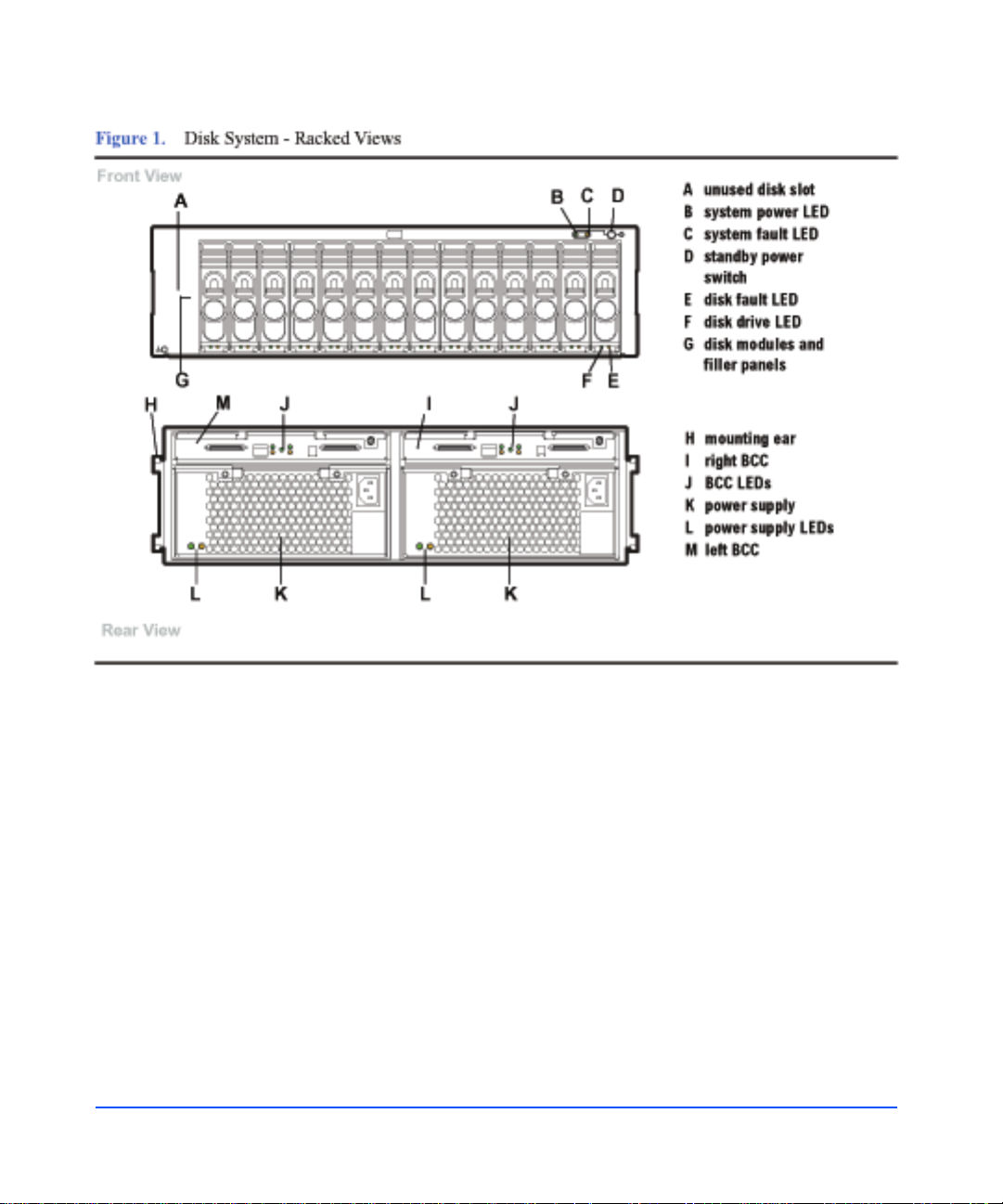
Figure 1 Disk System - Racked Views 14
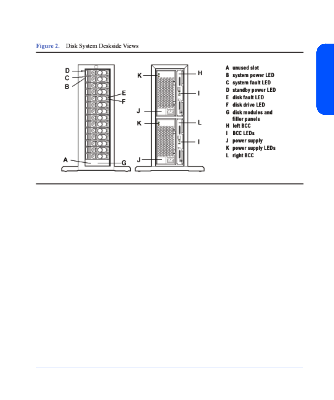
Figure 2 Disk System Deskside Views 15
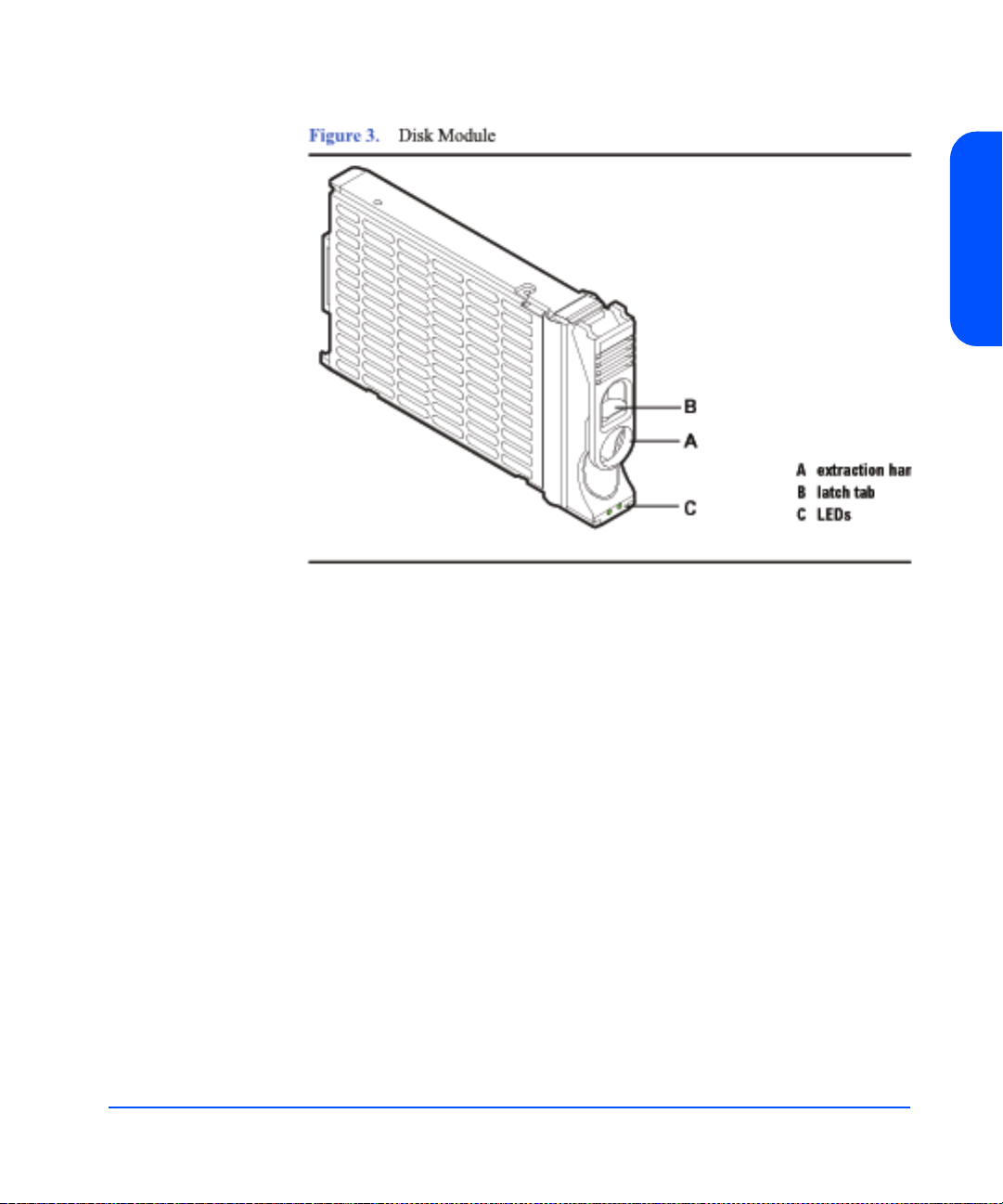
Figure 3 Disk Module 19
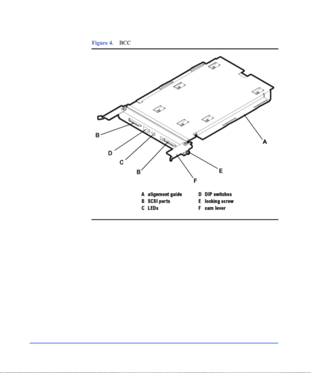
Figure 4 BCC 20
Figure 5 BCC Filler Panel 21
Figure 6 Power Supply/Fan Module 22
Figure 7 Basic Configuration - Single Host, Single Disk System 28
Figure 8 Single Host, Split Bus Configuration 29
Figure 9 Single Host PV-Links Configuration 30
Figure 10 Two Host Non-High Availability Configuration 31
Figure 11 Two Host High Availability Configuration 32
Figure 12 PDRU Placement in 1.6-Meter Rack 40
Figure 13 PDRU Placement in a 2.0-Meter Rack 41
Figure 14 Host Bus Adapter HP A5149A 43
Figure 15 Disk System Accessories 45
Figure 16 Disk System ContentsDisk System Contents 46
Figure 17 HP Rack System/E Rail Kit Contents 48
Figure 18 HP Rack System/E Installation Overview 49
Figure 19 Locating the site for the device installation in a System/E
Rack 51
Figure 20 Installing clipnuts for an HP Rack System/E 51
Figure 21 Installing rails in an HP Rack System/E 52
Figure 22 Installing the enclosure clipnut
53
Figure 23 Installing the storage device in the Rack System/E 54
Figure 24 Installing enclosure rail clamps in an HP Rack
System/E 55
Figure 25 HP Computer Cabinet Rail Kit Contents 56
Figure 26 HP Computer Cabinet Installation Overview 57
Figure 27 Locating the site for the device installation in an HP
Computer Cabinet 58
Figure 28 Installing rail clip nuts in the HP Computer Cabinet 59
Figure 29 Installing rails in the HP Computer Cabinet 60
7
Page 8

Figure 30 Installing enclosure retention clipnuts in an HP Computer
Cabinet 61
Figure 31 Installing the storage device in an HP Computer Cabinet 62
Figure 32 Installing a filler panel in an HP Computer Cabinet 63
Figure 33 Rittal-Style Rail Kit Contents 64
Figure 34 Rail Alignment 65
Figure 35 Front Screw Installation 66
Figure 36 Rear Slide Extension 67
Figure 37 Center Nut Tightening 67
Figure 38 Installing a Disk System into the Rittal-Style Rack 68
Figure 39 Moving a Disk System Retention Bracket 69
Figure 40 Bolting the Disk System to the Front Column of the Rack 69
Figure 41 BCC Installation 72
Figure 42 BCC Filler Panel 73
Figure 43 BCC DIP Switches 74
Figure 44 Wiring Scheme for 1.6-Meter Rack 76
Figure 45 Wiring Scheme for 2.0-Meter Rack 77
Figure 46 Disk Module Installation 78
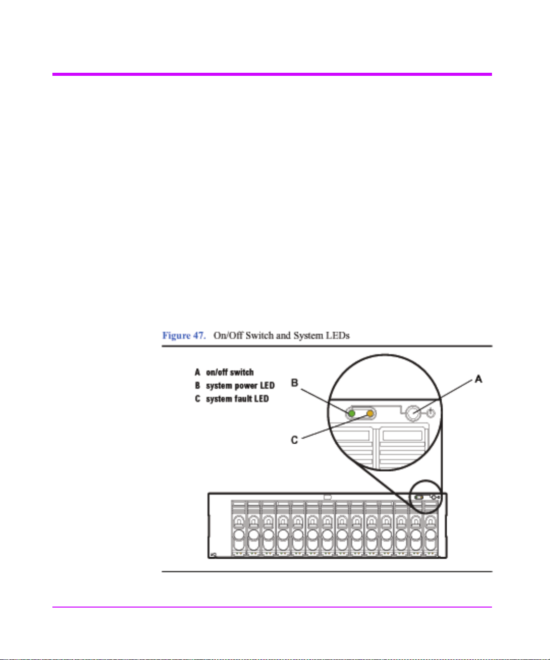
Figure 47 On/Off Switch and System LEDs 80
Figure 48 DIP Switches 86
Figure 49 Disk Module Slots and SCSI Addresses 89
Figure 50 Sample Hardware Event Notification 99
Figure 51 LED Status Indicators 101
Figure 52 Disk System Field Replaceable Units (FRUs) 108
Figure 53 Disk Module Removal 117
Figure 54 BCC Removal and Replacement 120
Figure 55 BCC DIP Switches 121
Figure 56 BCC Filler Panel Installation 122
Figure 57 Power Supply Removal and Replacement 124
Figure 58 Disk System Removal and Replacement 126
Figure 59 Top Cover Assembly 129
Figure 60 Midplane Assembly 132
Figure 61 End Cap Removal and Replacement 134
Figure 62 Base Removal and Replacement 135
Figure 63 Base Removal from Chassis 136
Figure 64 Removal from Cover 137
Figure 65 Installing Disk System into Cover 138
Figure 66 Installing Base to Cover and Chassis 139
Figure 67 End Cap Replacement 140
8
Page 9

tables
Table 1 Inrush (Surge) Current and Duration 36
Table 2 Maximum Operating Current 36
Table 3 Recommended PDU/PDRUs for Multiple Disk Systems in
HP Computer Cabinets 38
Table 4 Recommended PDU/PDRUs for Multiple Disk Systems in
HP System/E Racks 38
Table 5 Disk System Accessories 44
Table 6 Dis k System Conte nts 46
Table 7 Rail Positions for Sequential Disk Systems 50
Table 8 DIP Switch Settings 85
Table 9 DIP Switch Usage 87
Table 10 Disk and BCC SCSI Addresses for Full and Split Bus
Modes 88
Table 11 LED Functions 102
Table 12 Troubleshooting Table 104
Table 13 JBOD Enclosure Field Replaceable Units 109
Table 14 Upgrade Products 142
Table 15 PDU/PDRU Products 143
Table 16 Replacement and Exchange Part Numbers 144
Table 17 Product Weights 145
9
Page 10

10
Page 11

Product Description
General Description
Hewlett-Packard’s StorageWorks Disk System 2300 (referred to in this guide as
the disk system) is a high-availability Ultra160 SCSI storage product. Dual SCSI
ports on dual bus co ntrolle rs pr ovide LVD connections to the ho st. Fo urteen slots
accept high-speed, high-capacity LVD SCSI disks connected to an LVD
midplane. Maximum data throughput is 160 Mbytes/sec. Thirteen disk systems
fill a 2-meter System/E rack. Filled with 18-Gbyte disks, the 2-meter Rack
System/E yields 3.3 Terabytes of storage; with 36-Gbyte disks, 6.6 Terabytes of
storage and with 73-Gbyte disks, 13.3 Terabytes.
Modular and redundant components are easy to upgrade and maintain. Disks,
power supply/fan modules, and bus control cards (BCCs) are replaceable parts
that plug into individual slots in the front and back of the disk system. Redundan t
power supply/fan modules, and BCCs can be removed and replaced without
interrupting storage operations. Disks also can be replaced with the system on
and with only the affected file systems taken off-line. Hewlett-Packard technical
support is optional for these procedures.
1
Special electronics and HP-UX software enable remote monitoring and
diagnostics. Sensors on the BCCs monitor the disk system environment,
including temperature, voltage, fan speed, and component status. HewlettPackard’s Command View SDM reports any changes in environmental status to
user-defined locations. Standard HP-UX diagnostic utilities also report
environmental data for enhanced troublesho oti ng.
Product Description 11
Page 12

HP Command View SDM (Software Device Manager) software is designed to
provide storage management for HP dis k systems. This software, available on the
HP Command View SDM CD-ROM, provides simple, yet sophisticated device
management tools for t he disk s ystem. HP Command View SDM is supported on
the following:
■ HP-UX 11.00 (see Support Plus web site for the required patches)
■ HP-UX 11.11 (see Support Plus web site for the required patches)
■ Windows NT 4.0 (Service Pack 6a or greater)
■ Windows 2000 (Service Pack 1 or greater)
■ Linux Red Hat 7.2
HP T opT o ols is a web-based, devi ce management tool that enables administrator s
and MIS managers to use a web browser to obtain information about devices on
their network. It provides specific management to the following HP products:
■ HP Vectra and Brio Desktops
■ HP Kayak and Visualize Workstations
■ HP Omnibook Notebooks
■ HP Netservers
■ HP Procurve and AdvanceStack networking devices
■ HP LaserJet and JetDirect products
12 Product Description
■ HP Jornada PC Companions
■ HP StorageWorks products
■ HP Network Attached Storage (NAS) products
■ HP-UX systems with EMS
■ Windows systems
Page 13

Features
Product Description
The disk system occupies 3 EIA units in a standard 19-inch rack. Disk drives
mount in the front of the system. Redundant power supplies, and BCCs mount in
the back. See Figure 1 and Figure 2 below. For disk slots and SCSI addressing,
see Figure 49.
Product Description 13
Page 14
14 Product Description
Page 15
Status Indicators
Product Description
LEDs on the disk system enable you to detect and replace failed components and
so prevent or minimize users’ downtime. For additional information about LEDs,
see Chapter 4, Troubleshooting.
On the front of the disk system, a pair of LEDs indicates the status of the disk
system, and an LED for each slot shows disk I/O activity:
■ The system power LED (B in Figure 1) indicates that power is on or off.
■ The system fault LED (C in Figure 1) indicates whether or not a fault has
occurred anywhere in the disk system.
■ At the bottom of each disk module, the left LED (F in Figure 1 ) indicates the
presence of I/O activity on the disk.
■ The second LED on each disk module (E in Fig ure 1) can be flashed to help a
customer engineer (CE) locate the disk for physical inspection or removal.
■ The second LED is also used as a fault indicator for that specific disk module.
LEDs (I and K in Figure 2) on the back of the disk system indicate the status of
replaceable components and the SCSI bus: See Chapter 4, Troubleshooting, for
specific LED information.
Product Description 15
Page 16

Power/Standby Switch
Located at the upper right corner of the fron t of the disk system, the power switch
(D in Figure 1) interrupts DC power from the power supplies to the BCCs and
other internal components. Input AC power to the power supplies is controlled by
the power cords and the AC source.
High Availability
High availability is a general term describing computer systems that are designed
to minimize planned and unp lan ned dow n t ime. The di sk s ys tem supports current
systems’ high availability requirements through the following feat ures:
■ Hot-pluggable, high-capacity, high-speed disks
■ Redundant, hot-pluggable, user-replaceable power supplies and BCCs
■ Online firmware upgrades
■ Hardware event monitoring and real-time error reporting
Clustering (NT)
The HP Disk System 2300 is Microsoft® Cluster certified for a variety of
solutions. For specific information about supported configurations, see the
Hewlett-Packard Company or Microsoft web pages:
http://hp.com
http://microsoft.com
Upgradability
16 Product Description
You can increase disk system storage capacity by:
■ Replacing disk drives with higher-capacity disk drives
■ Adding disks in unused slots
None of these actions require shutting down the product, but some may require
the use of system utilities to manage file systems.
Upgrade BCC and disk fi rmware usin g an on-line download function. See
Chapter 3, Upda ting Firmware.
Page 17

Environmental Services
Environmental services circuitry monitors the following elements:
■ Fan rotation
■ Power supply output
■ Power supply status (fan status)
■ Disk drive status, presence
■ BCC status
■ Temperature
■ Self-test results
Each BCC reports the status of all elements in the disk system, even if the BCC
does not have direct access to the element.
Additionally, the EEPROM on each BCC stores 2 Kbytes of configuration
information and user-def ined data, includin g the manufacturer serial n umber , and
product number.
Hardware Event Monitoring
A hardware event monitor monitors the disk system and reports change s in
environmental status to Hewlett-Packard’s Event Monitoring System (EMS) for
HP-UX. Hardware event monitoring is an important tool for implementing high
availability. Using hardware event monitors, you can virtually eliminate
undetected hardware failures that interrupt system operation or cause data loss.
The EMS Hardware Monitors User’s Guide is available in Ado be
format on the HP document web site, http://www.docs.hp.com/hpux/systems/.
®
Acrobat®
Product Description
Product Description 17
Page 18

Components
User-replaceable components enable high availability and easy maintenance.
This section describes the following components:
■ Disks and disk fillers
■ BCCs and BCC fillers
■ Power supply/fan modules
Disk Modules and Disk Module Filler Panels
Disk modules, shown in Figure 3, contain 3.5-inch Low Profile Ultra 3 LVD
disks.
The disk module’s components are protected by a metal grill on the disk
module’s bottom side.
WARNING Disks require careful handling and ESD precautions.
The plastic parts of the disk are safe to touch:
■ Extractor handle (A in Figure 3)
■ Latch tab (B)
You may also safely touch the top and bottom of the disk module without
damaging the disk module .
18 Product Description
A metal grill protects exposed circuits against damage when the disk module is
laid circuit-side down on a flat surface.
The initial disk options for this product are 18-GByte, 36-GByte, and 73-Gbyte
10 K RPM disk drives. 18-GByte and 36-GByte 15 K RPM disk drives are also
supported. A label on the disk carrier shows the storage capacity and rotational
speed of the installed disk. Obtain information about the latest disk options from
HP sales representatives.
Caution Fillers must be installed in unused slots in order to maintain even
cooling for the installed disk modules.
Page 19
BCCs and BCC Filler Panels
BCCs (Bus Control Cards) plug into two slots in the back of the disk system.
Each BCC connects to both LVD (low voltage differential) buses inside the disk
system. In full bus mode (DIP switch 1 set to “|”), both BCCs have access to all
installed disks. The two SCSI buses are bridged. If either BCC fails and LVM
primary and alternate paths are defined, data can be accessed through the other
BCC. In split bus mode (DIP switch 1 set to “0”), the left BCC (as viewed from
the rear of the disk system), is on the high numbered bank (with disk slots 8, 9,
10, 11,12, 13, and 14) and the ri gh t BC C is o n t h e l ow n umb ered bank (with disk
slots 0, 1, 2, 3,4, 5, and 6) of disk slots. See Figure 1.
Product Description
Two SCSI ports (B in Figure 4) on each BCC provide dual LVD connections to
the same or separate hosts. If a host is connected to one of the BCC ports, an
LVD terminator must be connected to the other port on that BCC.
Product Description 19
Page 20
20 Product Description
Other features of the BCC are:
■ LEDs (C) indicating BCC status and bus configuration
■ DIP switches (D) on the rear panel:
1 Bus Mode (full or split bus)
2 Monitor Mode (SAF-TE or SES)
■ Locking thumbscrews (E)
■ Cam levers (F)
Page 21
BCC circuitry provides the following functions:
■ Bus configuration (see “Setting DIP Switches” in Chapter 3)
■ Bus expansion (LVD)
■ SCSI environmental services (see page 17)
■ System fault detection
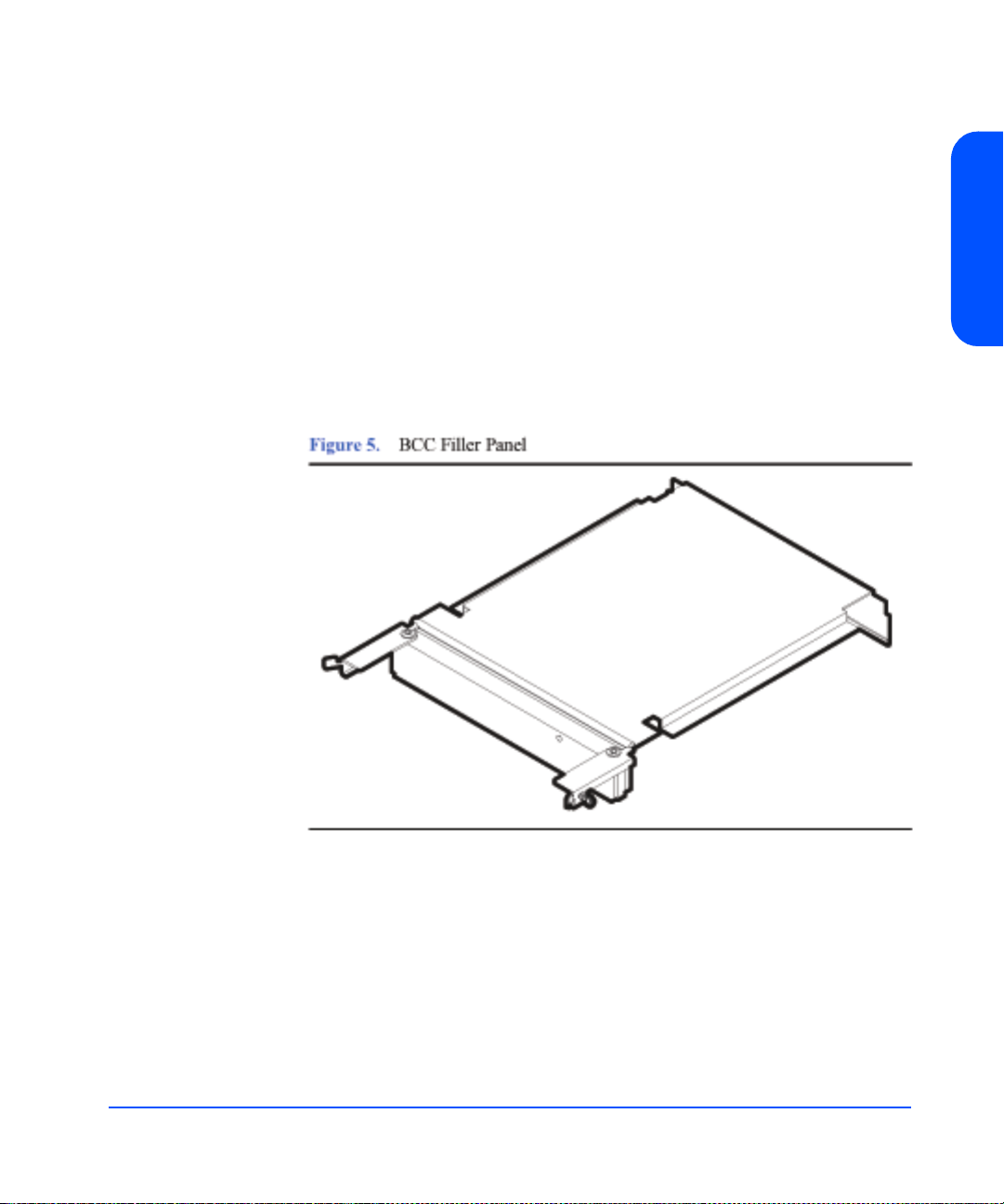
A BCC filler panel (Figure 5) replaces the second BCC when redundancy is not
required.
Caution The BCC filler panel maintains even cooling inside the disk
system when the second BCC is not present. A BCC filler panel
must be installed if the BCC is removed.
Product Description
Product Description 21
Page 22
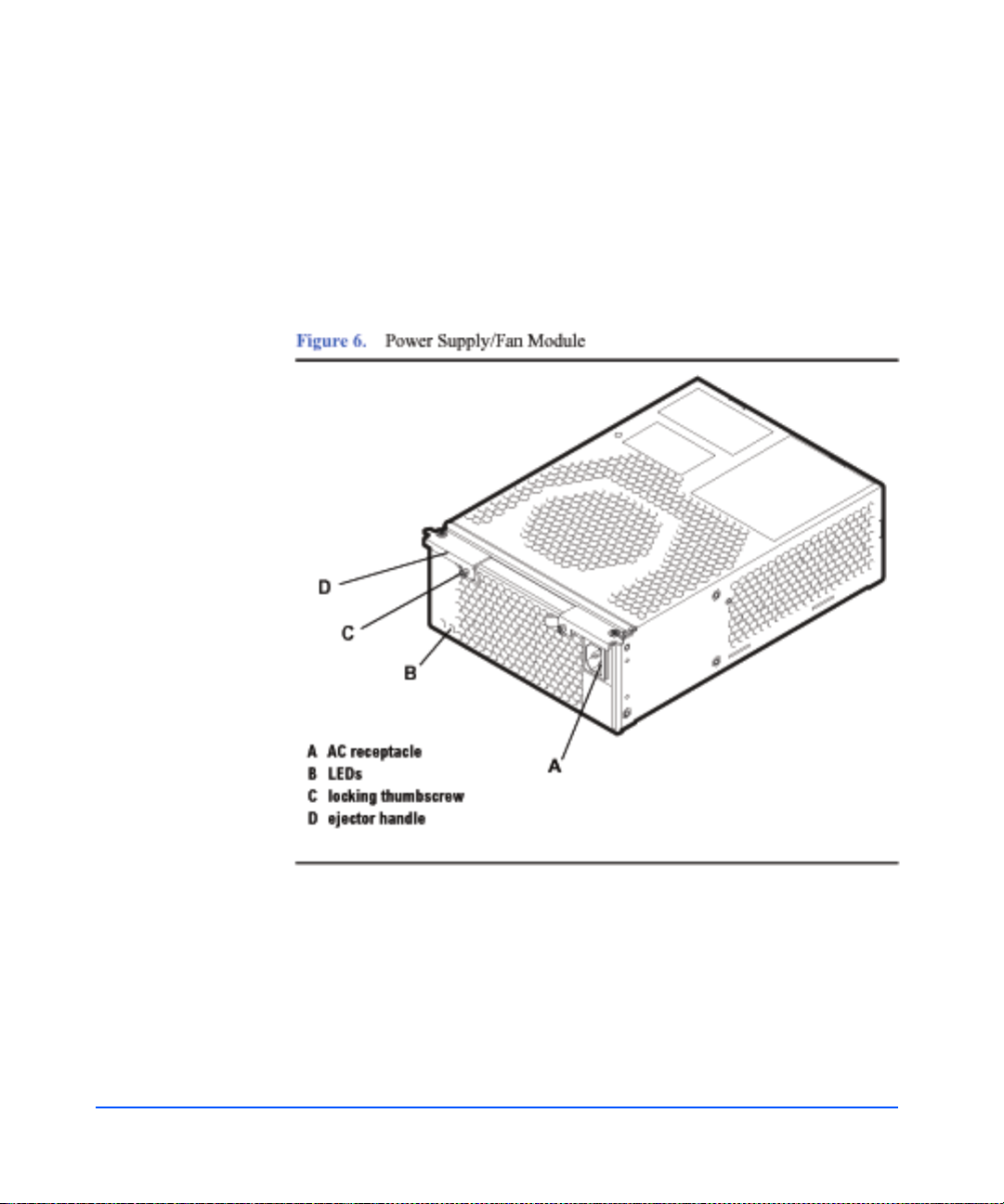
Power Supply/Fan Module
Redundant, hot-pluggable 340-watt power supplies convert wide-ranging AC
voltage from an external main to stable DC output and deliver it to the midplane.
Each power supply has an internal fan, an AC receptacle (A in Figure 6), two
ejector handles (D) with thumbscrews (C), and 2 LEDs (B). Internal control
prevents the rear DC output connector from becoming ener gi zed when the power
supply is removed from the disk system.
22 Product Description
Page 23

Power supplies share the load reciprocally; that is, each supply automatically
increases its output to compensate for reduced output from the other, and vice
versa. If one power supply fails, the other delivers the entire load.
Internal circuitry triggers a fault when the internal fan or other part fails. At the
same time, the power fault LED (amber) illuminates, and, if enabled, the
hardware event monitor sends an event message. The power supply fan remains
on if other parts fail in order to maintain cooling air flow through the system. If
the fan fails, the power supply shuts down. The fan in the other working power
supply will increase to full speed to compensate for the failed fan. The failed
power supply/fan module must be removed and the replacement power supply/
fan module installed within two minutes. In the event of a failure, if a
replacement fan module/power supply is not available, leave the failed power
supply/fan module installed until you are ready to replace it. This should be done
to maintain proper cooling for the disk system.
Internal circuitry senses fan motion and triggers a fault when the speed of the
power supply’s internal fan falls below a critical level. At the same time, the LED
turns amber, and , if en abled, the hardware event monitor sends an event message.
Product Description
Product Description 23
Page 24

Hardware/Software Requirements
The disk system is supported on the following operating systems:
■ HP-UX 11.00 with HWE 0302 (March 2002 Patch bundles) or greater
■ HP-UX 11.11 with HWE 0302 (March 2002 Patch bundles) or greater
■ Linux Red Hat 6.2, 7.0, 7.1
■ Windows NT 4.0 (Advanced Server, Enterprise Edition)
■ Windows 2000 (Server and Adva nced Server)
■ Microsoft Windows.Net (Serve r and Advanc ed Server)
■ SCO UnixWare 7.11
■ SCO OpenServer 5.06
■ HP MPE/iX 7.0
The following SCSI host bus adapters (HBAs) support the Disk System 2300:
■ A4999A, Ultra2 Low Voltage Differential SCSI Host Bus Adapter for B-,
C-, J-, and X-Class systems
■ A5140A Single Port Ultra 2 S CSI HBA Host bus adapt er for A-, L- , V-Class,
and Superdome.
■ A5149A, Single Port Ultra 2 SCSI HBA (PCI bus) Host bus adapter for
rp54X0, rp7400, rp7410, and rp8400 servers and A-, N-, L-, V-Class, and
Superdome systems (Full length card ).
24 Product Description
■ A5150A, Dual Port Ultra 2 SCSI (PCI bus) Host bus adapter for rx4610 and
rx9610 servers and A -, N- , L- , V-Class, and Superdom e sy st ems (F ull l eng th
card).
■ A5159A, Dual Part FWD SCSI PCI Host bus adapter for rx4610 and rx9610
servers
■ A5838A, Dual-Port 100Base-T/Dual-Port Wide Ultra2 Host bus adapter for
A-, N-, L-, V-Class, and Superdome systems.
■ A5856A, RAID 4Si - 4-Port Ultra2 LVD/SE RAID Host bus adapter for
rp54X0, rp7400, rp7410, and rp8400 servers, and A-, N-, L-, V-Class, and
Superdome systems.
■ A6828A, Single Port Ultra 160 SCSI HBA (PCI bus) Host bus adapter for
rp54X0, rp7400, rp7410, and rp8400 servers, and A-, N-, L-, V-Class, and
Superdome systems (Full length card ).
Page 25

■ A6829A, Dual Port Ultra160 SCSI (PCI bus) adapter Host bus adapter for
rp54X0, rp7400, rp7410, and rp8400 servers and A-, N-, L-, V-Class, and
Superdome systems (Full length card).
The following host bus adapters are supported on HP Netservers:
■ C7430A, PCI Ultra2 wide Host bus adapter
■ D5025A, HP Ultra/Wide SCSI Host bus adapter for Netservers
■ D9161A, NetRAID 4M/64MB Cache Host bus adapter for HP Netservers
■ D9351A, NetRAID 4M/128MB Cache Host bus adapter for HP Netservers
■ P3413A, Single port Ultra160 SCSI Host bus adapter for HP Netservers
Product Description
Product Description 25
Page 26

The following HP Netserver models are supported by the Disk System 2300:
■ rc7100
■ tc7100
■ tc 6100
■ tc4100
■ tc3100
■ rx4610
■ LXr8000
■ LXr8500
■ LH3/LH3r
■ LH4/LH4r
■ LH3000/LH3000r
■ LH6000/LH6000r
■ LC2000/LC2000r
■ LT6000
■ LPr
■ LP1000r
■ LP2000r
26 Product Description
■ E45/E50
■ E55/E60
■ E200/E200se
■ E800
The following host bust adapters are not supported at this time:
■ D2140A, NetRAID 1Si Host bus adapter
■ D5955A, NetRAID 3Si Host bus adapter
■ P3410A, NetRAID 1M Ultra160 SCSI Host bus adapter with 64MB
■ P3411A/B, NetRAID 2M Ultra160 SCSI Host bus adapter with 64MB
■ P3475A/B, NetRAID 2M Ultra160 SCSI Host bus adapter with 128MB
Page 27

Topologies
Product Description
The disk system supports high availability through redundan t comp onent s an d
redundant connections to redundant hosts. Each SCSI port on a BCC can be
connected to a different host bus adapter in the same or different hosts. Internal
mirroring within the disk system is also poss ible.
Basic high availability topologies are described on the following pages. For
information about specific supported topologies, consult an HP sales
representative.
This disk system can hold up to 14 disk modules. The maximum number of disk
modules can be installed in either Full Bus Mode or Split Bus Mode. However,
host and disk drive addressing must be closely managed.
Full Bus Mode
The maximum of 14 disk modules can be supported in Full Bus Mode provided
there there is only one host bus adapter (HBA) connection and the HBA has the
SCSI address of 7.
If more than one host connection is required, the slot with the SCSI address
corresponding to the SCSI address of the additional host must not have a disk
module installed in it to avoid bus contention. For example, if two connections
are made to a Disk System 2300 with HBAs having SCSI addresses of 6 and 7,
then SCSI ID 6 (slot 7)must not have a disk module installed in it.
Note SCSI address 15 should never be used by an HBA when
connecting to a Disk System 23 00 because this address is reserved
on the SCSI bus for the enclosure services microprocessor.
Connecting one disk system to redundant hosts achieves system level high
availability. A single host bus adapter in each host is connected to a dif ferent port
in the disk system. W ith the disk system in full bu s mode (s witch 1 on ), each host
can reach all the disks. If the right BCC (viewed fr om the r ear of the disk system)
fails in this topology, there is still one path to the disks through BCC B. With the
disk system i n split bus mode (two internal busses), the Disk System 2300
supports data mirroring between the two internal busses with in the same disk
system. All connections from the host to the disk system are SCSI LVD cables.
Product Description 27
Page 28
Another type of high availability topology connects mirrored disk system s to
redundant hosts. Dual host bus adapters in each host are connected to mirrored
disk systems. W ith the disk s ystems in fu ll bus mo de (switch 1 on), each hos t can
reach all disks in both disk systems. If one of the disk systems fails in this
topology, all hosts will still have access to the data on the mirrored disk system.
All connections from the host to the disk system are SCSI LVD cables.
28 Product Description
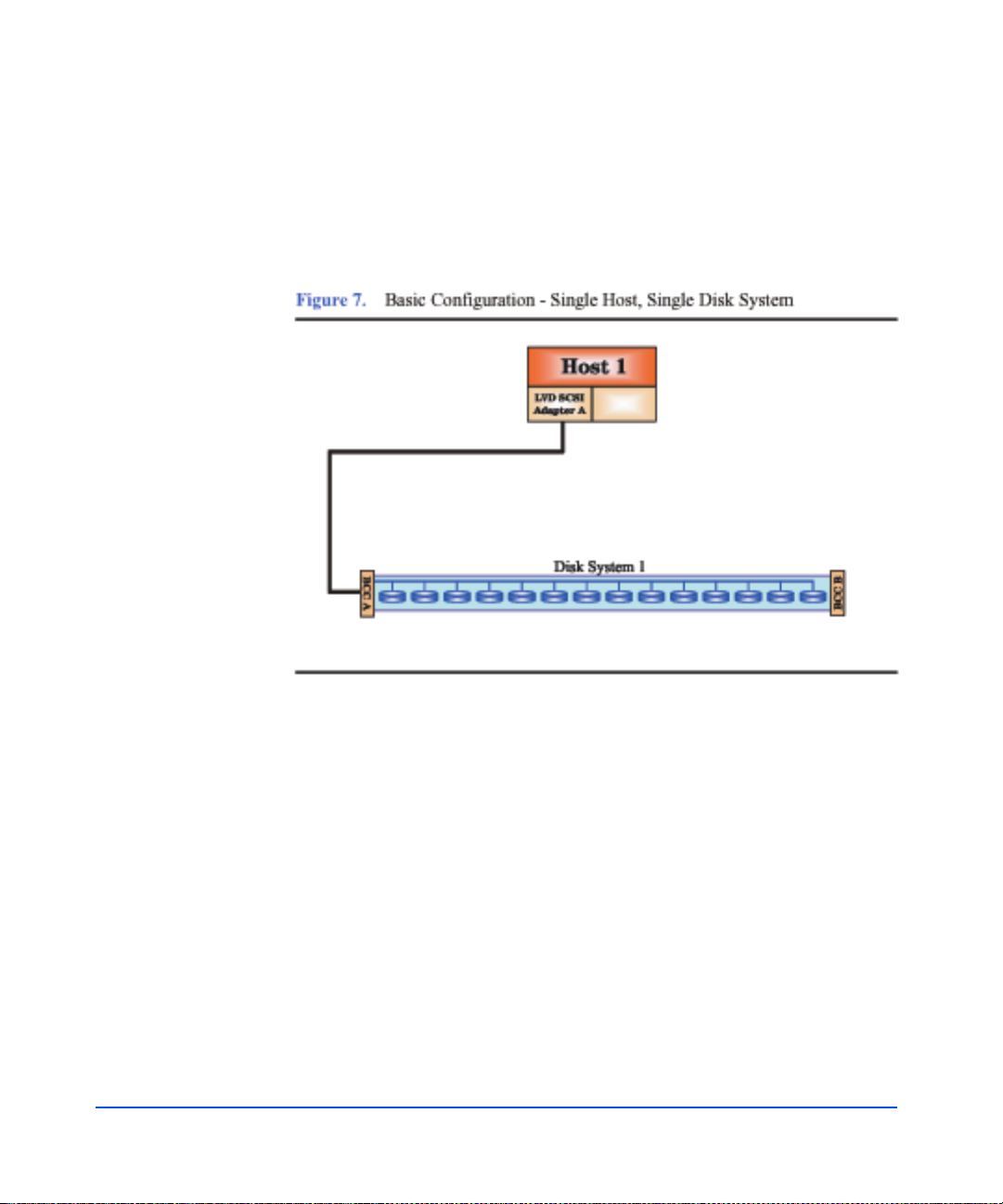
Due to SCSI ID limitations, daisy chaining of the Disk System 2300 is not
supported. The maximum storage capacity with this type of configuration is
approximately one Terabyte. This configuration does not provide any redundant
paths to the data, however there is some hardware redundancy provided by the
disk system hardware (i.e . power supply/fan modules and BCCs). T hi s
configuration can be used for boot, root, swap, or file system storage. Using
Mirror/UX software, one or more mirrors can be created on the same hardware
path to provide a basic level of data p rotection.
In figures 7 through 11, any BCC shown with only one cable connection should
be understood to have a terminator attached to the other SCSI connector.
Page 29
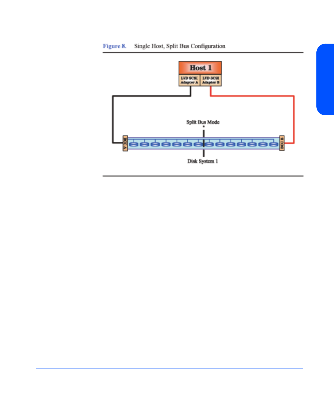
The disk system can be connected to a single host with two host bus adapters
(HBAs) in a split bus configuration. See Figure 8. Each HBA will do reads and
writes to a maximum of seven disks. This confi gu rati on can prov ide a maxi mum
capacity of approximately 1.1 Terabytes. This configuration can also do basic
mirroring across different hardware paths, still providing a maximum data
capacity of approximately 0.5 Terabytes. This configuration can also yield a
maximum performance of 320 MB/s, since each BCC card is capable of 160MB/
s performance in a split bus mode.
Product Description
Product Description 29
Page 30
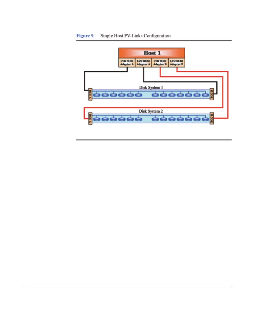
Data path redundancy can be secured with the configuration shown in Figure 9.
Using an additional host bus adapter (HBA) and the LVM s oftware, alternate
links can be created, providing a redundant path to data for each disk system. In
addition, a separate mirror path can be created for data protection. This
configuration provides protection against any single component failure (i.e.,
cables, HBAs, disks). Figure 9 depicts connecting two disk systems to a single
host.
The only limit on the number of disk systems per system is the maximu m number
of supported HBAs. For large configuration, it is recommended that multiple
CPUs have large amounts of memory to handle the system load. Each disk
system in this configuration is capable of 160MB/s performance. Due t o SCSI ID
limitations, a maximum of 13 disks is supported per disk system (13 disks + 2
HBAs + 1 SES = 16 SCSI IDs).
30 Product Description
Page 31

For customers with small data storage needs, a single disk system can be
connected to two hosts in a split bus mode. Each host can do reads and writes to a
maximum of seven disk modules. Each BCC can provide disk system status to
the host it is connected to. Each host can operate independently of the other.
System reboots and shutdowns do not need to be coordinated between the hosts.
In a split bus configuration, the two SCSI buses are physically isolated. Problems
on one bus are transparent to the other bus.
Product Description
Product Description 31
Page 32
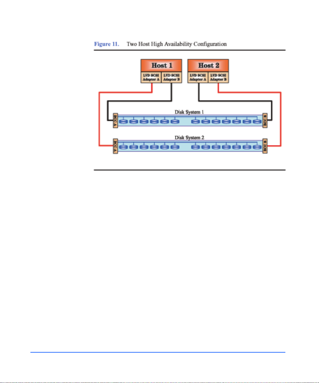
A two-host configu ration could be constr ucted usin g the Disk System 2300. Each
disk system could still be configured using mirrors. High availab ility software
will protect against a system failure. See Figure 11, above.
32 Product Description
Page 33

Definitions
Product Description
The following terms have specific meanings in the context of this guide:
High availability (HA)
HA describes hardware and software systems that are designed to
minimize planned and unplanned downtime. High availability is
measured at the system level and stated as the percentage of time the
system is in a state to do useful work; for example, 99.95% availability
translates to four hours of downtime per year.
Hot-pluggable
Hot-pluggable signifies the ability of a component to be installed or
replaced without interrupting storage operations and within the
restrictions of the operating environment. All customer-replaceable
disk system components can be replaced under power. Adding or
replacing disks or BCCs may require the use of HP-UX commands to
manage file systems.
JBOD
Pronounced jay-bod, a JBOD (Just a Bunch Of Disks) is an enclosed
group of disks.
LVD
LVD (Low Voltage Differential) is a type of SCSI signalling that filters
out common mode noise by taking the difference of two low-voltage
signals. LVD supports cable lengths up to 25 meters including SCSI
cable lengths inside devices on the bus. The disk system’s connection
to the host is LVD.
PDU and PDRU
PDUs (power distribution units) distribute power from a single inlet to
multiple outlets. PRUs (power relay units) connect one or more PDU
inlets to a single on/off switch, such as a cabinet power switch. Units
that both distribute and switch power are referred to as PDRUs.
Product Description 33
Page 34

Ultra160 SCSI
Ultra160 is a SCSI interface that transfers 160 Mbytes/sec for wide
busses.
34 Product Description
Page 35

Installation
2
Installation 35
Page 36

Preparation
Before installing the disk system, make sure (1) electrical wiring, breakers, and
PDUs meet power needs, (2) the required support software is installed on the
host, and (3) if you are connecting the disk system to a V-class server, autotermination is enabled on the host bus adapter. This section covers all three of
these topics.
Electrical Requirements
All electrical wiring to the service point (plug) must be sized to carry the
appropriate inrush (20 amps per power supply) and steady state currents. See
Table 1 for examples.
Table 1 Inrush (Surge) Current and Duration
No. of Disk Systems
on Circuit (2 power
supplies per disk system)
1 40 amps declining over 100 ms (5 cycles)
2 80 amps declining over 100 ms (5 cycles)
3 120 amps declining over 100 ms (5 cycles)
Inrush Current and Duration
36 Installation
4 160 amps declining over 100 ms (5 cycles)
Table 2 Maximum Operating Current
Incoming Voltage
AC RMS
Maximum RMS Current Drawn by One Disk
System
100 – 120 volts 4.8 amps
200 – 240 volts 2.0 amps
Caution Adding disk systems to 120V circuits rapidly increases amp
requirements. Always make sure that the total current drawn does
not exceed circuit capacity.
Page 37

Circuit breakers must be adequately rated for inrush and operating currents.
Hewlett-Packard recommends magnetic-type circuit breakers, which are capable
of handling large inrush currents for short durations (10 to 12 cycles) and are
rated adequately for steady state currents.
Choosing PDUs
Peak power requirements and PDU capacity affect the number of disk systems
that can be installed in a rack. For example, to install more than four disk systems
in Hewlett-Packard Rack Systems/E (HP Models J1500A(1.96M),
J1501A(1.6 0M), or J1502 ( 1.25M)), you must upgrade to 19-inch PDUs.
Besides rack density, the following factors can help you choose PDUs:
■ Redundant power source. To connect redundant power supplies t o separate
PDUs, install redundant PDUs.
■ Number of cords to the AC source. Using 30-amp PDRUs instead of 16-amp
PDUs reduces the number of cords to the wall.
■ Future needs. Installing surplus PDU capacity allows you to add disk system
units later.
■ Inrush margins. For installations that require four or more 16-amp PDUs,
Hewlett-Packard recommends HP 30-amp PDRUs (E7681A, E7682A) for
their inherent inrush protection.
■ On/Off switch capability. Some PDU/PDRU options support the use of a
single-point on/off switch. See Figure 12 and Figure 13.
Installation
The following tables show how many and what kind of PDU/ PDR U s are needed
to install one or more disk systems in an HP rack. Data assumes 220V AC
nominal power and redundant PDU/PDRUs. For nonredundant configurations,
divide the number of recommended PDU/PDRUs by 2.
Installation 37
Page 38

Table 3 Reco mmended PDU/PDRUs for Multiple Disk Systems in HP
Computer Cabinets
No. of
Disk
Systems
1.1 meter (21 U) 1.6 meter (32 U) 2.0 meter (41 U)
1 – 5 2 3-foot/16-amp
PDUs
or
2 19-inch/16-amp
PDUs
6 – 8 NA** 4 19-inch/16-amp PDRUs or
9 – 10 NA** NA** 4 19-inch/30-am p
2 5-foot/16-amp or
PDUs*
4 19-inch/30-amp PDRUs
2 19-inch/16-amp
PDUs
PDRUs
* Supports cabinet on/off switch.
**Rack height does not allow additional disk systems.
Table 4 Reco mmended PDU/PDRUs for Multiple Disk Systems in HP System/
E Racks
No. of
Disk
Systems
1 – 4 2 19-inch/16-amp or 2 19-inch/30-amp PDRUs*
5 – 8 NA** 2 19-inch/30-amp PDRUs*
1.25 meter (25 U) 1.6 meter (33 U) 2.0 meter (41 U)
PDUs
4 19-inch/30-amp PDRUs
38 Installation
9 – 11 NA** NA** 4 19-inch/30-amp
PDRUs
12 - 13 NA** NA** 4 19-inch/30-amp
PDRUs
* Supports the cabinet on/off switch option.
**Rack height does not allow additional disk systems.
Page 39

Installing PDUs
The 19-inch PDUs and PDRUs can be installed vertically or horizontally in the
rack. Choose PDU/PDRU locations with the following guidelines in mind:
■ Place PDU/PDRUs within the reach of disk system cords.
■ Place PDU/PDRUs vertically whenever possible. See sample installations in
Figure 12 and Figure 13. Installing PDU/PDRUs horizontally interferes with
the ability to service disk systems that are behind the PDU/PDRU.
■ Place vertical PDU/PDRUs on each side of the disk system so that the cord
from either power supply does not cross over replaceable components in the
middle of the product.
■ To achieve maximum density in 2-meter racks, install 30-amp PDRUs on
hinged brackets directly behind disk systems. Hinges allow the PDRU (HP
E7681A and E7682A) to swing aside for servicing obscured components.
(See Figure 13.)
Installation
Installation 39
Page 40

40 Installation
Page 41

Installation
Installation 41
Page 42

Software Requirements
Ensure that the minimum revisions of HP-UX extension software and online
diagnostics are installed. These release packages enable CommandView SDM
and EMS for the disk system.
1. At the host console, enter swlist | grep HWE and lo ok for the following
2. Enter swlist | grep Online and l ook for the following online di agnostics
If swlist does not report the specified releases, install them from th e la test
CD-ROM in any of the following products:
— For HP-UX 11.00:
extension software according to the installed HP-UX revision:
HP-UX 11.00 with HWE 0302
HP-UX 11.11 with HWE 0302
according to the installe d HP-UX revision:
- Online Diags B.11.00.20.09, or greater, on HP-UX
11.00
- Online Diags B.11.11.06.09, or greater, on HP-UX
11.11
o B3920EA HP-UX OE Media for Servers
o B6261AA HP-UX 11.00 Extension Upgrade Media Kit
42 Installation
— For HP-UX 11.11:
o B3920EA HP-UX OE Media for Servers
o B6191AA HP 9000 Support Plus Media
o B6821AA HP-UX TCOE Media
o B6845AA HP-UX 11.11 Minimal Technical OE Media
o B7993AA HP-UX Enterprise OE Server Media
o B7994AA HP-UX Mission Critical OE Comm. Media
The external IT Resource Center web site is:
http://us-support3.external.hp.com/
Page 43

Auto-Termination
Auto-termination is disabled when a shunt is installed over both pins on
the TP2 pinset. To enable auto-ter mination, rem ove t he shunt en tirely o r
move it to only one of the pins. The result must be open pins, as shown
in Figure 14. Verify that auto-termination is enabled on the host system.
For other H BAs, check t he document ation for you r particular host bus
adapter.
Installation
Installation 43
Page 44

Step 1: Gather Tools
Once the electrical, software, and special V-class preparations are complete,
collect the tools you need to install the disk system hardware:
■ Torx T25 screwdriver
■ Torx T15 screwdriver
■ Small flat-blade screwdriver
Step 2: Unpack the Product
1. Lift off the overcarton and verify the contents of the accessories (top) box.
See Table 5 and Figure 15.
Table 5 Disk System Accessories
Figure
Label
Part (part number)
A User guide (A6490-96001)
B Quick installation guide (A6490-96003)
C Disk Modules and filler panels (A6198-60002)
D BCC (A6491-60001)
E BCC filler (A6490-67002)
F LVD terminator (5021-1121)
- Racking Kits not shown
44 Installation
Page 45

2. Lift off the accessories box and the top of the under box, and verify
the contents shown in Table 6 and Figure 16.
Installation
Installation 45
Page 46

Table 6 Disk System Contents
46 Installation
Figure
Label
Part (part number)
A Installation Manual (A6490-96003)
B Two power cords (8120-6514)
C SCSI Cable (see Reference Section for part numbers)
D Disk System Chassis (A6490-60100)
If a part is missing, contact an HP sales representative.
Page 47

Step 3: Install the device
Follow the procedures in this section to install your storage device in one of the
following rack systems:
■ HP Rack System/E
■ HP Computer Cabinet
■ Rittal-Style Rack
Installing the Storage Device into a Rack System/E
Your storage device can be installed into any of these HP Rack System/E
Products:
■ A4902A HP Rack System/E41 (1.96 M; 41U)
■ A4901A HP Rack System/E33 (1.60 M; 33U)
■ A4900A HP Rack System/E25 (1.10 M; 25U)
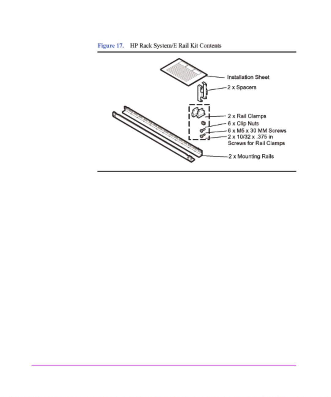
1. Check the rail kit contents (see Figure 17). If any parts are missing, call your
nearest HP sales office.
Installation
Installation 47
Page 48
48 Installation
Page 49

2. Study the installation overview (see Figure 18).
Installation
The following tools are required for the installation of the storage device:
■ Flat-blade screwdriver
■ T25 nut driver
WARNING To ensure cabinet or rack stability and avoid possible injury,
always install the storage devices in the rack or cabinet from the
bottom up.
Installation 49
Page 50

3. Locate a place on the rack columns with t he avai lab le spac e requir ed
for the installation of the storage device. The storage device and the
rail kit require 3 EIA units of space .
Use the following table as a guide for placement of the rails in a Rack System/E
where multiple disk systems will be installed. You can rack multiple disk systems
without gaps installing rails every three EIA units. For example, starting at the
bottom of a 2-meter rack, set rails at the following unit/hole locations:
Table 7 Rail Positions for Sequential Disk Systems
Disk Systems Hole from Rack Bottom
One 1
Two 4
Three 7
Four 10
Five 13
Six 16
Seven 19
Eight 22
50 Installation
Nine 25
Ten 28
Eleven 31
Page 51

4. Install clipnuts as shown in Figure 20.
Figure 20. Installing clipnuts for an HP Rack System/E
Installation
Installation 51
Page 52

5. Insert the rail tabs into the appropriate column holes (see Figure 21).
6. Secure the rail end s with one M5 screw each.
7. Install clipnuts on the front columns of the cabinet (see Figure 22).
These are used for the retention bracket screws.
52 Installation
Page 53

8. Place the storage device on the rails and slide it into the cabinet until
the retention bracket comes in contact with the rack column (see
Figure 23).
WARNING An empty storage device weighs more than 54 pounds (24.5 kg)
(without disk modules installed). To avoid personal injury, it is
recommended that two people install the storage device in the
rack.
Installation
Installation 53
Page 54

9. Insert and tighten the storage device retention (M5) screws through
the retention bracket (se e Figure 23).
54 Installation
Page 55

10. Place a rail clamp on each rail and slide them to each bottom rear
corner of the storage device.(see Figure 24).
11. Secure the clamps to the rails. Use one 10-32 screw for each rail clamp.
Installation
Installation 55
Page 56

Installing the storage device into an HP Computer Cabinet
Your storage device can be installed into the following Computer Cabinets:
■ C2785A Computer Cabinet (1.10M; 21U)
■ C2786A Computer Cabinet (1.60M; 32U)
■ C2787A Computer Cabinet (1.96M; 41U)
Caution To ensure proper installation, only use the instructions in this
manual for installing the storage device in the HP Computer
Cabinet. Do not use the instructions enclosed in the rail kit box.
1. Check the rail kit contents (see Figure 25). If any parts are missing, call your
nearest HP sales office. The tie-dow n clamp is not used and may be discarded.
56 Installation
Page 57

2. Study the installation overview (see Figure 26)
Installation
The following tools are required for the installation of the storage device:
■ Flat-blade screwdriver
■ T25 nut driver
WARNING To ensure cabinet or rack stability and avoid possible injury,
always install storage devices in the rack or cabinet from the
bottom up.
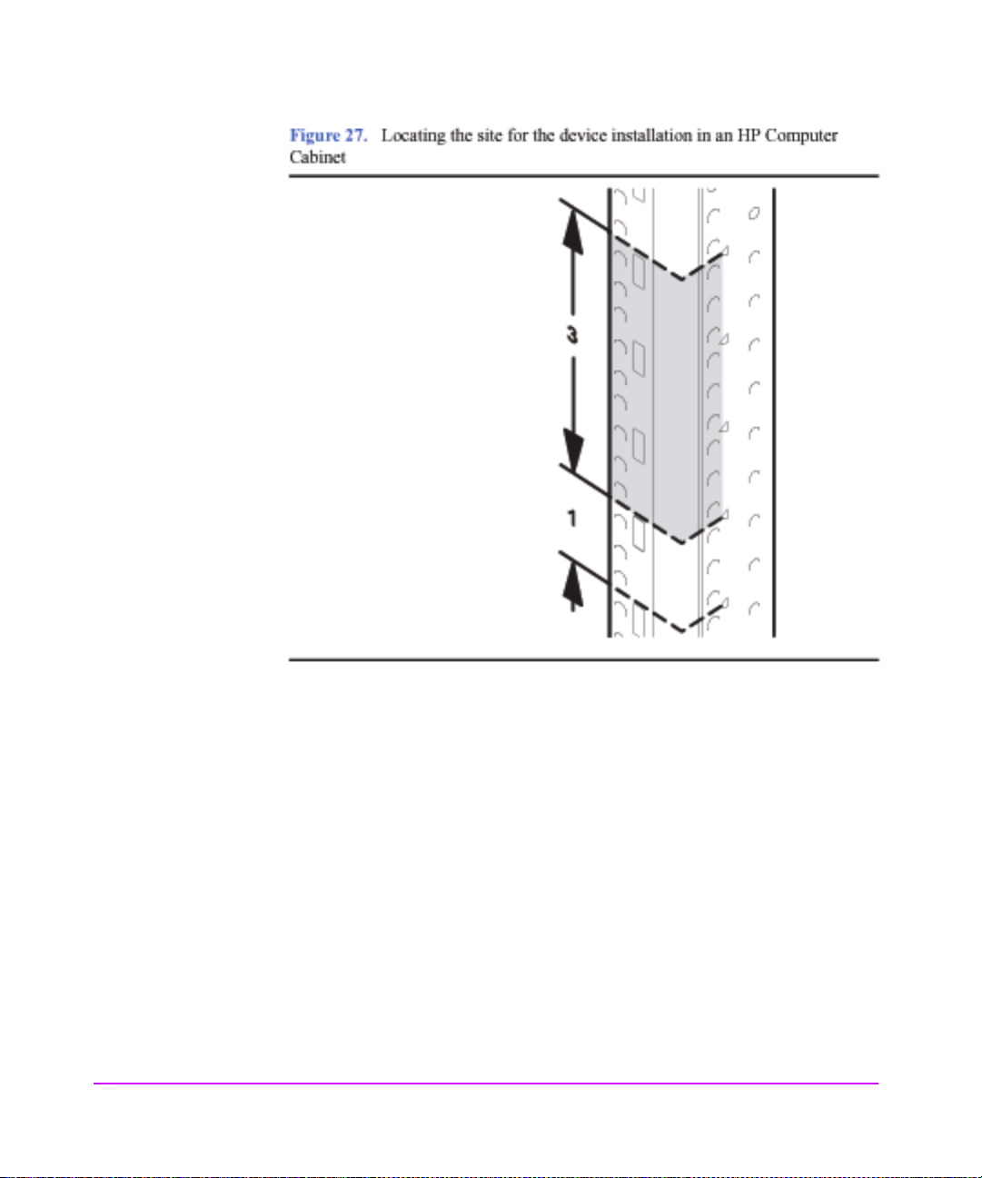
3. Locate a place on the rack columns with t he avai lab le spac e requir ed
for the installation of the storage device. The storage device and the
rail kit require 4 EI A units of s pace, thr ee units f or the sto rage de vice
and one unit for the rails (see Figure 27).
Installation 57
Page 58
58 Installation
Page 59

4. Install clipnuts as shown in Figure 28
Installation
Installation 59
Page 60

5. Insert the rail tabs into the appropriate holes on the HP Computer
Cabinet co lumns (see Figure 29).
6. Secure the rail end s with one M5 screw each.
Figure 29. Installing rails in the HP Computer Cabinet
B
Arail tab
B clip nut
A
60 Installation
Page 61

7. Install clipnuts on the front columns of the cabinet (see Figure 30).
These are u sed for the device retention screws.
8. Place the storage device on the rails and slide it into the cabinet until
the retention bracket comes in contact with the rack column (see
Figure 31).
Installation
WARNING An empty storage device weighs approximately 54 pounds
(without disk modules installed) (24.5 kg). To avoid personal
injury, it is recommended that two people install the storage device
in the rack.
Installation 61
Page 62

9. Tighten the stor age device retention (M5) scr ews through the retention
bracket (see Figure 31).
62 Installation
Page 63

10. Install a filler panel in the space below the storage device.
If a filler panel is required, it must be ordered separately. Contact
your local HP sales repr esentative for assistance.
Installation
Installation 63
Page 64

Installing the Storage Device into a Rittal-Style Rack
Your storage device can be installed into the Rittal-Style Rack by doing the
following steps:
1. Inspect the contents of the rail kit. If any parts are missing, call yo ur neares t
HP sales office. See Figure 33.
64 Installation
Page 65

2. Align the front of rails to the inside of the front cabinet column.
Carefully observe the alignment of the groups of holes on the columns so
the holes in the rails align properly.
Installation
Installation 65
Page 66

3. Insert and finger tighten the rail mounting screws.
Use the third and seventh holes from the top of rail to mount the rail to the
front column of the cabinet.
4. Extend the adjustable slide to the back column of the cabinet.
5. Insert the mounting screws and finger tighten them through the rear
column of the cabinet.
66 Installation
Page 67

6. Tighten the center nuts to finger tightness.
Figure 37. Center Nut Tightening
7. Tighten all screws to their final tightness using a driver.
Installation
Tighten the screws that hold the rail to the columns first, before
tightening the center slide nuts to their final tightness.
Installation 67
Page 68

8. Repeat the procedure above for the other rail.
9. Insert the disk system (with disk modules and power supplies
removed) onto the
rails.
10. Move the disk system retention brackets to the frontmost set of
mounting holes.
68 Installation
This allows the disk system to install further back into the cabinet; and
so, allows the cabinet doors (if present) to close properly.
Page 69

11. Push the disk system back into the rack until the disk system retaining
bracket is flush against the front column of the rack.
12. Bolt the disk system to the front column. Use the fifth hole from the
top of the fr ont of the rail.
Figure 40. Bolting the Disk System to the Front Column of the Rack
Installation
Installation 69
Page 70

Install the Disk System
1. Remove the power supply/fan modules to prepare the disk system for lifting:
WARNING Do not attempt to lift the disk system without the help of another
2. Remove the disk modules from t he disk system. Place th em as id e on
3. Carry the disk system to the front of the rack and slide the back end
4. Secure the disk system as appropriate f or the rail kit and cabinet at the
a Loosen the screws in each extractor handle of each power supply/fan
module with the chassis still in the box.
b Pull the extractor handles out from the center of the power supply to
disengage the it from the midplane. Pull each power supply/fan module
out of the chassis. Support the far end of the power supply/fan module
with your free hand as it clears the chassis.
c Set the power supply/fan module aside, on an antistatic pad, to be
reinstalled later.
person or a lift device. Even without power suppl i es and disk
drives, the disk system weighs 54 pounds.
the pink anti-static foam pad supplied with your disk system.
onto the rails (Figure 38) with the help of another person or using a
lifting device. Push the d isk system into the rack as far as it will go.
installation site.
70 Installation
Page 71

Step 4: Install BCCs
The disk system comes with one or two BCCs, depending on the option
purchased. If you are installing only one BCC, you will install a BCC filler in the
open BCC slot.
1. Attach your ESD strap to ground.
2. Unpack the BCC from the accessories box and ESD bag.
WARNING Do not touch the pins on the back of the BCC.
3. Loosen the locking screws (D in Figure 41) if necessary on the BCC
cam latches.
4. Open the BCC cam latches (C in Figure 41) by pulling them away
from the cen ter.
5. Align the BCC alignment guides (E) wi th the slot, and insert the BCC
into the the left slot at t he back of the disk system. S top pushing when
the BCC meets the midplane.
6. Press the cam latches inward and f lat against the center . The cam action
draws the BCC completely into the slot and seats the connector pins
on the midplane.
7. Tighten the locking screw (D).
Installation
Installation 71
Page 72

72 Installation
8. If you have a second BCC, repeat steps 2 through 6, installing the
second BCC in the right slot.
Page 73

9. If you do not have a second BCC, install the BCC filler as follows:
a Unpack the BCC filler from the accessories bo x.
b Align the filler panel edges with the appropriate slot and insert the filler
into the open slot until the cam handles engage.
c Press the cam handles toward the center of the BCC until they are against
the face of the filler panel.
d Tighten the locking thumbscrew (see Figure 42).
Installation
Installation 73
Page 74

Step 5: Set DIP Switches
BCCs are shipped from the factory with all DIP switches (see Figure 43) in the
“|” position. The pull-out label on top of the disk system identifies each switch
position.
Caution DIP Switch settings must be the same on both BCCs. If settings
Set dip switches as needed. See Chapter 3, Configuration, for switch definitions
and guidelines.
There is a switch bank that is recessed from the BCC bulkhead. Typically, they
do not need to be reset. The BCC must be removed from the disk system to
access this switch bank. See switch bank 2 in Chapter 3. Also see Tables 33 and
34 for switch settings and usage.
differ, the disk system will fail its power-on self-test and the disks
will not be accessible through the second BCC.
74 Installation
Page 75

Step 6: Connect SCSI and Power Cables
1. Attach an LVD SCSI cable to SCSI port A or B, on one or both BCCs. (Sample
topologies appear in Chapter 1.)
2. Attach the other end of each SCSI cable to a host bus adapter. (See
bus configuration options in Chapter 3.)
3. Attach an LVD terminator to any empty SCSI port that is on a BCC
with a cable attached.
The terminators can be found in bags tethered to the BCC locking
thumbscrew(s).
4. Plug a power cord into the AC receptacle of each power supply.
5. Attach the other end of each power cord t o a preinstalled PDU/PDRU.
Choose outlets according to the following guidelines:
— Redundancy . To extend the redundancy of the product, attach each cord to
a different PDU. This is represented in Figure 44 and Figure 45 by the
absence of duplicate letters in each disk system.
— Reliability. To avoid cascading faults for a group of disk systems that are
plugged int o the same PDU, distribute redundant power cords to as many
different combinations of PDUs as possible. This is represented in
Figure 44 and Figure 45 by the least number of duplicate pairs of letters
among all disk syst em s . Ca scading faults occur when a backup PDU is
overloaded with power surges after the primary PDU fails.
— Serviceability. Choose PDU locations that prevent power cords from
interfering with the removal and replacement of serviceable components.
Also leave a 6-inch service loop to allow for the rotation of PDRUs.
Installation
The letters A, B, C, D, E and F in the following diagrams represent independent
PDUs or PDU banks. The absence of duplicate letters in individual disk systems
indicates the products are using redundant PDUs. The minimal number of
duplicate letter pairs indicates the disk systems are protected against cascading
faults.
Installation 75
Page 76

76 Installation
Page 77

Installation
Installation 77
Page 78

Step 7: Install Disk Modules
Caution Touching exposed areas on the disk can cause electrical discharge
and disable the disk. Be sure you are grounded and be careful not
to touch exposed circuits.
Disk modules are fragile and ESD sensitive. Dropping one end of the disk just
two inches is enough to cause permanent damage. In addition, static electricity
can destroy the magnetic properties of recording surfaces. Grip disks only by
their handles (A in Figure 46) and carriers (D), and follow strict ESD procedures.
78 Installation
Page 79

1. Determine which slots, 1 through 14, will contain disk modules and which
will contain fillers.
— If DIP switch 1 is set to “|” (full bus mode), choose any slots for disk
modules or fillers. In full bus mode, the SCSI address 7 is reserved for the
host bus adapter. If more than one host bus adapter connects the disk
system to othe r hosts, then a di sk module mus t be removed from the slot
whose SCSI address corresponds to the SCSI address of the additional
host bus adapter. The most host bus adapters supported on this disk
system is two.
— If DIP switch 1 is set to “0” (split bus mode), the left BCC is on the high
numbered bank (with disk slots 8, 9, 10, 11,12, 13, and 14) and the right
BCC is on the low numbered bank (with disk slots 0, 1, 2, 3, 4, 5, and 6)
of disk slots.
— At least on e disk module must be inst alled.
2. Put on the ESD strap and attach the other end to ground.
Caution Disk modules are fragile. Handle carefully. Be careful to grasp the
disk module by its handle and avoid touching exposed circuitry.
3. V erify that the disk mod ule extraction handle (A in Figure 46) is open
by placing a finger behi nd the extracti on handle and pushing t he latch
tab toward your finger.
4. Align and insert the disk module into its slot.
Installation
5. Push the disk module as far as it will go into the selected slot.
Note Install disks left to right for easier insertion.
6. Close the cam latch by pushing the extraction handl e toward the disk
until it clicks. The cam act ion draws t he disk modul e complete ly into
the slot and seats the connecting pins on the midplane.
7. Repeat steps 4 through 7 to install additional disk modules.
8. Install disk fillers in the remaining slots.
Caution Every slot must contain either a disk module or filler panel for
proper cooling.
Installation 79
Page 80
Step 8: Turn on the Disk System
Caution When starting up the disk system, do not override automatic spin-
up by issuing SCSI start commands to the drives. Doing so could
cause an overcurrent fault, requiring a power cycle to recover.
Press in the power/standby switch with the retracted tip of a pen or pencil to
power-on the array (see Figure 47). Allow 2 minutes for the disk drives and
controllers to complete their self-tests.
1. Press the power switch (A in Figure 47) to turn on the disk system.
2. Watch the system LEDs for confirmation that the disk system is
operational. The sy stem power LED (B) should be green , and the fault
LED (C) should be off.
If the LEDs indicate a problem, refer to Chapter 4, Troubleshooting.
Note An amber light that is on briefly when a component turns on is
normal. If this light remains on more than a couple of seconds, a
fault has been detected.
80 Installation
Page 81

Step 9: Verify Devices on the Host
On an HP-UX host run IOSCAN (ioscan -f) and verify th at the disks and BCC( s)
are listed in IOSCAN output. If the displayed “S/W State” is not “claimed,”
begin troubleshooting (see Chap t er 4).
Sample IOSCAN
The example shows a fully loaded disk system. The BCC ca rd is at hard ware path
0/1/0/0.15.0
Class I H/W Path Driver S/W State H/W Type Description
==============================================================================
ext_bus 5 0/3/0/0 c8xx CLAIMED INTERFACE SCSI C1010 Ultra160
target 22 0/3/0/0.0 tgt CLAIMED DEVICE
disk 51 0/3/0/0.0.0 sdisk CLAIMED DEVICE HP 36.4GST336706LC
target 23 0/3/0/0.1 tgt CLAIMED DEVICE
disk 52 0/3/0/0.1.0 sdisk CLAIMED DEVICE HP 36.4GST336706LC
target 24 0/3/0/0.2 tgt CLAIMED DEVICE
disk 53 0/3/0/0.2.0 sdisk CLAIMED DEVICE HP 36.4GST336706LC
target 25 0/3/0/0.3 tgt CLAIMED DEVICE
disk 54 0/3/0/0.3.0 sdisk CLAIMED DEVICE HP 36.4GST336706LC
target 26 0/3/0/0.4 tgt CLAIMED DEVICE
disk 55 0/3/0/0.4.0 sdisk CLAIMED DEVICE HP 36.4GST336706LC
target 27 0/3/0/0.5 tgt CLAIMED DEVICE
disk 56 0/3/0/0.5.0 sdisk CLAIMED DEVICE HP 36.4GST336706LC
target 28 0/3/0/0.6 tgt CLAIMED DEVICE
disk 57 0/3/0/0.6.0 sdisk CLAIMED DEVICE HP 18.2GST318406LC
target 21 0/3/0/0.7 tgt CLAIMED DEVICE
ctl 25 0/3/0/0.7.0 sctl CLAIMED DEVICE Initiator
target 29 0/3/0/0.15 tgt CLAIMED DEVICE
ctl 21 0/3/0/0.15.0 sctl CLAIMED DEVICE HP A6491A
ba 4 0/4 lba CLAIMED BUS_NEXUS Local PCI Bus
ext_bus 9 0/4/2/0 c8xx CLAIMED INTERFACE SCSI C1010 Ultra160
target 30 0/4/2/0.7 tgt CLAIMED DEVICE
ctl 26 0/4/2/0.7.0 sctl CLAIMED DEVICE Initiator
target 22 0/4/2/0.8 tgt CLAIMED DEVICE
disk 51 0/4/2/0.8.0 sdisk CLAIMED DEVICE HP 36.4GST336706LC
target 23 0/4/2/0.9 tgt CLAIMED DEVICE
disk 52 0/4/2/0.9.0 sdisk CLAIMED DEVICE HP 36.4GST336706LC
target 24 0/4/2/0.10 tgt CLAIMED DEVICE
disk 53 0/4/2/0.10.0 sdisk CLAIMED DEVICE HP 36.4GST336706LC
target 25 0/4/2/0.11 tgt CLAIMED DEVICE
disk 54 0/4/2/0.11.0 sdisk CLAIMED DEVICE HP 36.4GST336706LC
target 26 0/4/2/0.12 tgt CLAIMED DEVICE
disk 55 0/4/2/0.12.0 sdisk CLAIMED DEVICE HP 36.4GST336706LC
target 27 0/4/2/0.13 tgt CLAIMED DEVICE
disk 56 0/4/2/0.13.0 sdisk CLAIMED DEVICE HP 36.4GST336706LC
target 28 0/4/2/0.14 tgt CLAIMED DEVICE
disk 57 0/4/2/0.14.0 sdisk CLAIMED DEVICE HP 18.2GST318406LC
target 29 0/4/2/0.15 tgt CLAIMED DEVICE
ctl 21 0/4/2/0.15.0 sctl CLAIMED DEVICE HP A6491A
Wide LVD A6828-60001
Adapter (782)
Wide LVD A6829-60001
Installation
Installation 81
Page 82

The “descriptions” in this example represent some of the valid disk modules.
Valid disk descriptions include:
■ ST318404LC18-Gbyte 10K rpm LVD disk module
ST318406LC
■ ST336704LC36-Gbyte 10K rpm LVD disk module
ST336706LC
■ ST373405LC73-Gbyte 10K rpm LVD disk module
■ ST318452LC18-Gbyte 15K rpm LVD disk module
MAM3184MC
■ ST336752LC36-Gbyte 15K rpm LVD disk module
MAM3367MC
Where do you go from here?
For operating system and application configuration information, refer to the
documentation for your particular server’s operating system.
82 Installation
Page 83

Configuration
3
Configuration 83
Page 84

Viewing a Disk System in IOSCAN
An IOSCAN (example below) shows each BCC (0/1/0/0.15.0) and disk in the
disk system.
Sample IOSCAN
Type the command: ioscan -f
Class I H/W Path Driver S/W State H/W Type Description
==============================================================================
ext_bus 4 0/1/0/0 c8xx CLAIMED INTERFACE SCSI C1010 Ultra160
Wide LVD A6828-60001
target 6 0/1/0/0.0 tgt CLAIMED DEVICE
disk 34 0/1/0/0.0.0 sdisk CLAIMED DEVICE HP 18.2GST318406LC
target 7 0/1/0/0.1 tgt CLAIMED DEVICE
disk 35 0/1/0/0.1.0 sdisk CLAIMED DEVICE HP 18.2GST318406LC
target 8 0/1/0/0.2 tgt CLAIMED DEVICE
disk 36 0/1/0/0.2.0 sdisk CLAIMED DEVICE HP 18.2GST318406LC
target 9 0/1/0/0.3 tgt CLAIMED DEVICE
disk 24 0/1/0/0.3.0 sdisk CLAIMED DEVICE HP 18.2GST318406LC
target 10 0/1/0/0.4 tgt CLAIMED DEVICE
disk 37 0/1/0/0.4.0 sdisk CLAIMED DEVICE HP 18.2GST318452LC
target 11 0/1/0/0.5 tgt CLAIMED DEVICE
disk 42 0/1/0/0.5.0 sdisk CLAIMED DEVICE HP 18.2GST318452LC
target 11 0/1/0/0.6 tgt CLAIMED DEVICE
disk 42 0/1/0/0.6.0 sdisk CLAIMED DEVICE HP 18.2GST318452LC
target 12 0/1/0/0.7 tgt CLAIMED DEVICE
ctl 24 0/1/0/0.7.0 sctl CLAIMED DEVICE Initiator
target 13 0/1/0/0.8 tgt CLAIMED DEVICE
disk 8 0/1/0/0.8.0 sdisk CLAIMED DEVICE HP 18.2GST318452LC
target 14 0/1/0/0.9 tgt CLAIMED DEVICE
disk 18 0/1/0/0.9.0 sdisk CLAIMED DEVICE HP 18.2GST318452LC
target 15 0/1/0/0.10 tgt CLAIMED DEVICE
disk 19 0/1/0/0.10.0 sdisk CLAIMED DEVICE HP 18.2GST318452LC
target 16 0/1/0/0.11 tgt CLAIMED DEVICE
disk 22 0/1/0/0.11.0 sdisk CLAIMED DEVICE HP 18.2GST318452LC
target 17 0/1/0/0.12 tgt CLAIMED DEVICE
disk 20 0/1/0/0.12.0 sdisk CLAIMED DEVICE HP 18.2GST318452LC
target 18 0/1/0/0.13 tgt CLAIMED DEVICE
disk 23 0/1/0/0.13.0 sdisk CLAIMED DEVICE HP 18.2GST318452LC
target 19 0/1/0/0.14 tgt CLAIMED DEVICE
disk 21 0/1/0/0.14.0 sdisk CLAIMED DEVICE HP 18.2GST318452LC
target 20 0/1/0/0.15 tgt CLAIMED DEVICE
ctl 18 0/1/0/0.15.0 sctl CLAIMED DEVICE HP A6491A
84 Configuration
Page 85

Setting DIP Switches
T wo DIP switches on left sl ot BCC determine bus architectur e and some
bus behavior. If that BCC is removed, then the DIP switches on the
other BCC define the bus. See Table 8 for a description of switch
settings.
Table 8. DIP Switch Settings
Switch Bank 1 Off - | ON = 0
1 Full Bus
2 SES/SAF-TE
Creates a single bus of up
to 14 disk drives
SAF-TE Mode (SAF-TE
mode is the default. For
HP-UX using EMS, set
to SES)
Splits the bus into two
buses,
up to 7 disk drives each
SES mode
Switch Bank 2 Off - | ON = 0
1 Bus Reset: Hot
Swap Disk
2 Bus Reset:
Power Fail
3 Bus Reset:
Hot Swap BCC
Automatically issues a
SCSI bus reset when a
disk is removed or
inserted
Issues a SCSI reset
when the power
supply/fan module
indicates it will go
offline
Automatically issues a
SCSI bus reset when a
BCC is removed or
inserted
Lets the host detect
change and determine
action
Lets the host detect
change and determine
action
Note The switch settings on bot h BC Cs mu st ma tch. I f the disk
system is being connected to an HP-UX system, the
switch should be set to SES mode. If the disk system is
being connected to a Netserver, the switch should be set
to SAF-TE mode.
Configuration
If the BCC self-test detects any discrepancy, the buzzer sounds 4 or 5
times, and the BCC fault and system fault LEDs flash. If the system is
starting up, the disks do not spin up. If the system is operating, the disks
and second BCC continue to operate.
Configuration 85
Page 86

86 Configuration
Page 87

Rationale
Sites choose DIP switch options according to their priorities and
preferences. High availability sites, for example, may want automatic
bus reset on whereas high performance sites may choose to turn it off.
The following table gives some of the typical reasons for choosing
specific DIP switch settings.
Table 9. DIP Switch Usage
Switch 1
1. Full Bus a. Full-bus mode is the only
2. SES/
SAF-TE
Reasons to Set OFF
(|)
way to access all 14 disks
with one BCC.
b. With two BCCs, full-bus
mode allows two external
connections to the bus.
c. Full-bus mode with two
BCCs gives redundant
environmental services.
SAF-TE is required
for NT.
Reasons to Set ON
(0)
a. Split buses allow you to
mirror disks within the
disk system.
b. Split-bus mode uses
fewer
IDs on the bus, improving
bus performance.
SES is required for
HP-UX .
Switch 2 Reasons to Set OFF (|) Reasons to Set ON (0)
1. Bus Reset Hot Swap
Disk
2. Bus Reset Pwr Fail
3. Bus Reset Hot Swap
BCC
Automatic bus reset
reduces the chances of
data corruption and saves
the 30 to 60 seconds that
the host would spend
determining that a disk is
unavailable. Bus reset
signals the host to resend
outstanding I/O requests.
SCSI bus is held in reset
as power goes down, thus
avoiding data corruption
Automatic SCSI bus reset
reduces the chance of data
corruption when a BCC is
inserted or removed from
the disk system.
a. No bus reset reserves
bus control to the host.
b. No bus reset avoids
resetting the entire bus
for one disk.
Bus control is restricted
to the host.
a. No bus reset reserves
bus control to the host.
b. No bus reset avoids
resetting the entire bus
for one disk.
Configuration
Configuration 87
Page 88

Disk Addressing
Each disk in the StorageWorks Disk System 2300 occupies a separate address
(SCSI ID) on the SCSI bus. Disk addresses range from 0 to 6 and 8 to 14 in fullbus mode (DIP switch 1 set to “|”). In split bus mode (DIP switch 1 set to “0”),
the left BCC (viewing the disk system from the rear) is on the high numbered
bank (with disk slots 8, 9, 10, 11,12, 13, and 14) and the right BCC is on the low
numbered bank (with disk slots 0, 1, 2, 3,4, 5, and 6) of disk slots. Address 7 is
reserved for host bust adapter(s). The BCCs take address 15.
Table 10 shows all target SCSI IDs for full bus and split b us mo des.
Table 10. Disk and BCC SCSI Addresses for Full and Split Bus Modes
Physical
SCSI ID
Disk Slot
10 0
21 1
32 2
43 3
54 4
65 5
76 6
88 8
99
10 10 10
11 11 11
12 12
13 13
14 14 14
Right BCC 15 15
Left BCC B See Note 15
Full Bus
Split Bus
(Right BCC)
Split Bus
(Left BCC)
9
12
13
88 Configuration
Page 89

Note In split bus mode, the enclosure monitor circuitry on each BCC
Disk Slots and Addressing
utilizes SCSI address 15. This is allowable since each BCC is
connected to a separate SCSI bus. However, when the enclosure
configuration is in Full Bus mode, and the separate SCSI busses on
the midplane are connected together and there are two BCCs in the
enclosure, the secondary BCC does not connect to the SCSI bus.
The disk system has 14 available disk slots, SCSI addressing
does not follow a “1-to- 1” relat ionship be tween slot position s
and SCSI addresses. Sl ot assignment s and SCSI add resses are
shown in Figure 49.
Configuration
In full bus mode, the SCSI address 7 i s rese rv ed for the host bus adap ter. If more
than one host bus adapter connects the disk system to other hosts, then a disk
module must be removed from the slot whose SCSI address corresponds to the
SCSI address of the additional host bus adapter. The most host bus adapters
supported on this disk system is two.
In split bus mode, the loading sequence is from slot 1 to the right to slot 7 and
from slot 8 to the right to slot 14.
In full bus mode, begin loading the disk modules in slot 1 and continue installing
disk modules toward the right.
Configuration 89
Page 90

Setting Up the Hardware Event Monitor
Separate monitors watch over the disks and the disk system. You need to install
and configure the Disk Monitor (disk_em) and the High Availability Storage
System Monitor (dm_ses_enclosure) for complete event notification.
To install and configure the required monitors, refer to the EMS Hardware
Monitors User’s Guide, which is included in Adobe Acrobat format on IPR
Support Media. You can download a copy of Acrobat Reader without charge
from http://www.adobe.com/prodindex/acrobat/readstep.html.
For specific information about setting up hardware event monitoring using HP
CommandView SDM, see the HP Commandview SDM Disk System Installation
and User Guide, Version 1.04 (Part Number T1001-96006).
For specific information about setting up hardware event monitoring using HP
TopTools 5.5, see the HP TopTools 5.5 User G uide, Version 1.0 on the following
URL:
http://www.hp.com/toptools/doc/manuals.html.
Aliasing Devices (HP-Qualified Only)
Using host-based software, you can “label” each disk system with any
information that would be useful for the site . You might use this feature to assign
an inventory number or to indicate the location of the product. The maximum
length of the annotation is 256 characters. It appears in EMS event messages.
90 Configuration
For specific information about annotating devices, see the HP Commandview
SDM Disk System Installation and User Guide.
For specific information about annotating devices using HP T opTools 5.5, see the
HP TopTools 5.5 User Guide.
Page 91

Updating Firmware (HP-Qualified Only)
Obtain the latest disk or BCC firmware release from the su pport site
before traveling to the customer site.
For specific information about updating firmware, see the HP
CommandView SDM Disk System Installation and User Guide, Version
1.04.
For specific information about updating fir mwa re using HP TopTools
5.5, see the HP TopTools 5.5 User Guide.
Command View SDM
This configuration tool is supported on three different operating
systems:
■ HP-UX
■ Windows
■ Linux Redhat
Installation varies depending on the chosen operating system. After
installation, Command View SDM operation is virtually identical for all
three operating systems.
The Command View SDM software provides both server and client
applications. If you are operating as a client (on a host not directly
connected to the array), you must be assigned access permission to the
array from the server (host directly co nn ected to the array) to acces s the
array for Command View SDM management.
Note Examples in this section occasionally identify a path.
When only one path is shown, either Windows path
separators “\” or UNIX/Linux path separators “/” will be
used. If you use an example, use the path separators
appropriate for your operating system.
Configuration
Configuration 91
Page 92

Supported Operating Systems
The HP Command View SDM software is supported on the operating systems
listed below. Both the HP Command View SDM software and the Upgrade
License software products are supported on these operating systems. Minimum
system requirements for each operating system are identified in this section, prior
to the installation instructions for each operating system.
■ HP-UX 11.00 (for most current Support Plus patches, see HP-UX
Installation)
■ HP-UX 11.11 (for most current Support Plus patches, see HP-UX
Installation)
■ Windows NT 4.0 (Service Pack 6a or greater)
■ Windows 2000 (Service Pack 1 or greater)
■ Linux Redhat 6.2 and 7.0
New product support is continually being added for HP disk systems, such as
new operating syste m supp ort, h ardware configurat ions (Hosts /HBAs ), fir mware
upgrades, plus additional software products. To obtain the most current support
and product information, access the HP web site.
Installing CommandView SDM
For specific installation instructions for your operating system, see HP Co mmand
View SDM Disk System Installation and User Guide Version 1.04, part number
T1001-96006.
For Windows 2000 installation only:
92 Configuration
After the disk system is properly connected and Windows has been started,
follow the procedure below after the “Found new Hardware” pop-up dialog
appears:
1 Select "Search for drivers" and click “Next”.
2 Check the specify location check box, and click “Next”.
3 Click on the “Browse” button.
4 Use the file browser to locate and select the DS2300.inf file on the Command
View SDM CD in the \drivers\win directory (i.e. d:\drivers\win\DS2300.inf).
Click “OK”.
5 Click the next button to install the .inf file.
Page 93

HP TopTools
HP TopTools is a web- based, device management tool that enables
administra tors and MIS managers to use a web browser to obtain
information about devices on their network. It provides specific
management to the following HP products:
■ HP Vectra and Brio Desktops
■ HP Kayak and Visualize Workstations
■ HP Omnibook Notebooks
■ HP Netservers
■ HP Procurve and AdvanceStack networking devices
■ HP LaserJet and JetDirect products
■ HP Jornada PC Companions
■ HP StorageWorks products
■ HP Network Attached Storage (NAS) products
■ Wind ows sys t ems
Supported Operating Systems
HP TopTools is supported on the following operating systems:
Configuration
Installing HP TopTools 5.0
■ Windows NT 4.0 Service Pack 4, 5, or 6a. If none of these are
installed, the TopTools installation will install Service Pack 6a.
■ Window 2000 Professional or Server Editions
For specific installation instructions for your operating system, see HP
TopTools 5.5 User Guide. It can be found on the following URL:
http://www.hp.com/toptools/doc/manuals.html
Configuration 93
Page 94

94 Configuration
Page 95

Troubleshooting
4
Troubleshooting 95
Page 96

Overview
The following steps will help you identify and resolve disk sy stem failures:
1 Gather information from all sources:
— Hardware event notifications (page 97)
— Disk system LED stat us (page 101)
— Online information tools (page 104)
2 Isolate the cause of the problem (page 104).
3 Correct the problem (chapter 5, Removal and Replacement).
4 Verify operational status with IOSCAN or other host utilities.
96 Troubleshooting
Page 97

Event Notification (HP-UX Systems)
The EMS hardware event monitor polls
environmental services on the BCC and reports any
changes in the status of monitored components.
Depending on how the monitor is set up, you can
receive messages at the console, in e-mail, in a log
file, or through third-party applications. These
messages are likely to be the first indication of a
problem with a disk system.
Events are reported for changes in temperature,
voltage, and the status of replaceable components.
Messages identify five le vels of sever ity:
Critical An event that causes data loss, host system downtime, or
other loss of service. Host system operation will be affected if
the disk system continues to be used without correction.
Immediate action is required.
Serious An event that may cause data loss, host system downtime, or
other loss of service if left uncorrected. Host system and
hardware operation may be adversely affected. The problem
needs repair as soon as possible.
Major Warning An event that could escalate to a serious condition if not
corrected. Host system operation should not be affected and
normal use of the disk system can continue. Repair is needed
but at a convenient time.
Minor Warning An event that will not likely escalate to a severe condition if
left uncorrected. Host system operation will not be
interrupted and normal use of the disk system can continue.
The problem can be repaired when convenient.
Information An event that is expected as part of the normal operation of
the hardware. No action is required.
Troubleshooting 97
Troubleshooting
Page 98

Event messages (see Figure 50) contain the following:
■ Message Data – Date and time the message was sent, the source and
destination of the message, and the severity level
■ Event Data – Date and time of the event, the host, event ID, name of the
monitor, event number, event class, severity level, hardware path, associated
OS error log entry ID
■ Error Description – Narrative information indicating the component that
experienced the event and the nature of the event
■ Probable Cause/Recommended Action – The cause of the event and
suggested steps toward a solution. This information should be the first step in
troubleshooting.
■ Annotation – The user-defined annotation associated with the specific disk
system
98 Troubleshooting
Page 99

Figure 50. Sample Hardware Event Notification
Notification Time: Wed Feb 3 11:27:15 1999
yourserver sent Event Monitor notification information:
/storage/events/enclosures/ses_enclosure/8_0_1_0.15.0 is >=1.
Its current value is MAJORWARNING(3)
Event data from monitor:
Event Time: Wed Feb 3 11:27:15 1999
Hostname: yourserver.rose.hp.com IP Address : 15.43.213.13
Event ID: 0x0036b8a313000000002 Monitor : dm_ses_enclosure
Event # : 402 Event Class: I/O
Severity : MAJOR WARNING
Enclosure at hardware path 8/0/1/0.15.0: Hardware failure
Associated OS error log entry id(s): None
Description of Error:
The enclosure services controllers have different versions of
firmware.
Probable Cause / Recommended Action:
The enclosure services controller cards hav e different versions
of firmware. Update the controllers to the same version of
firmware.
User Defined Annotation: Enclosure 37 BCC A.
Troubleshooting
Troubleshooting 99
Page 100

HP Command View SDM
For specific information about using HP CommandView SDM for viewing the
disk logs and for other functions, see the HP CommandView SDM Dis k System
Installation and User Guide. This document can be found at the following URL:
TopTools
For specific information about using HP TopTools 5.5 for viewing disk logs and
for other functions, see the HP TopTools Version 5.5 User Guide. This document
can be found at the following URL:
http://h200002.www2.hp.com/bc/docs/support/
SupportManual/lpg29284/lpg29284.pdf
http://www.hp.com/toptools/doc/manuals.pdf
100 Troubleshooting
 Loading...