

HP AA988A, StorageWorks 2012sa User Manual

HP StorageWorks
2012sa Modular Smart Array
user guide
Part number: 488320-002
Second edition: July 2008

Legal and notice information
© Copyright 2008 Hewlett-Packard Development Company, L.P.
Hewlett-Packard Company makes no warranty of any kind with regard to this material, including, but not limited to, the implied
warranties of merchantability and fitness for a particular purpose. Hewlett-Packard shall not be liable for errors contained herein or for
incidental or consequential damages in connection with the furnishing, performance, or use of this material.
This document contains proprietary information, which is protected by copyright. No part of this document may be photocopied,
reproduced, or translated into another language without the prior written consent of Hewlett-Packard. The information is provided “as is”
without warranty of any kind and is subject to change without notice. The only warranties for HP products and services are set forth in the
express warranty statements accompanying such products and services. Nothing herein should be construed as constituting an
additional warranty. HP shall not be liable for technical or editorial errors or omissions contained herein.
Microsoft and Windows are U.S. registered trademarks of Microsoft Corporation.

3
Contents
About This Guide . . . . . . . . . . . . . . . . . . . . . . . . . . . . . . . . . . . . . . . . . . . . . . . . . . . 7
Intended Audience . . . . . . . . . . . . . . . . . . . . . . . . . . . . . . . . . . . . . . . . . . . . . . . . . . . 7
Prerequisites . . . . . . . . . . . . . . . . . . . . . . . . . . . . . . . . . . . . . . . . . . . . . . . . . . . . . . . . 7
Document Conventions . . . . . . . . . . . . . . . . . . . . . . . . . . . . . . . . . . . . . . . . . . . . . . . 8
Rack Stability . . . . . . . . . . . . . . . . . . . . . . . . . . . . . . . . . . . . . . . . . . . . . . . . . . . . . . . 8
HP Technical Support . . . . . . . . . . . . . . . . . . . . . . . . . . . . . . . . . . . . . . . . . . . . . . . . . 9
Customer Self Repair . . . . . . . . . . . . . . . . . . . . . . . . . . . . . . . . . . . . . . . . . . . . . . . . . 9
Product Warranties . . . . . . . . . . . . . . . . . . . . . . . . . . . . . . . . . . . . . . . . . . . . . . . . . . . 9
Subscription Service . . . . . . . . . . . . . . . . . . . . . . . . . . . . . . . . . . . . . . . . . . . . . . . . . 10
HP Websites . . . . . . . . . . . . . . . . . . . . . . . . . . . . . . . . . . . . . . . . . . . . . . . . . . . . . . . 10
Documentation Feedback . . . . . . . . . . . . . . . . . . . . . . . . . . . . . . . . . . . . . . . . . . . . . 10
1. System Components . . . . . . . . . . . . . . . . . . . . . . . . . . . . . . . . . . . . . . . . . . . . . . . . 11
System Management Software . . . . . . . . . . . . . . . . . . . . . . . . . . . . . . . . . . . . . . . . . 12
HP StorageWorks MSA2000 Family Storage Management Utility (SMU) . . . . 12
Command-Line Interface (CLI) . . . . . . . . . . . . . . . . . . . . . . . . . . . . . . . . . . . . . 12
Hardware Components and LEDs . . . . . . . . . . . . . . . . . . . . . . . . . . . . . . . . . . . . . . 13
Controller Enclosure Components and LEDs . . . . . . . . . . . . . . . . . . . . . . . . . . 13
Drive Enclosure Components and LEDs . . . . . . . . . . . . . . . . . . . . . . . . . . . . . . 20
2. Installing and Cabling Enclosures . . . . . . . . . . . . . . . . . . . . . . . . . . . . . . . . . . . . . 25
Site Planning . . . . . . . . . . . . . . . . . . . . . . . . . . . . . . . . . . . . . . . . . . . . . . . . . . . . . . 25
Required Tools . . . . . . . . . . . . . . . . . . . . . . . . . . . . . . . . . . . . . . . . . . . . . . . . . . . . . 25
Safety Precautions . . . . . . . . . . . . . . . . . . . . . . . . . . . . . . . . . . . . . . . . . . . . . . . . . . 26

4 HP StorageWorks 2012sa Modular Smart Array user guide • May 2008
Installation Checklist . . . . . . . . . . . . . . . . . . . . . . . . . . . . . . . . . . . . . . . . . . . . . . . . 27
Installing Enclosures Into a Rack . . . . . . . . . . . . . . . . . . . . . . . . . . . . . . . . . . . . . . . 28
Preparing the Rack . . . . . . . . . . . . . . . . . . . . . . . . . . . . . . . . . . . . . . . . . . . . . . 28
Assembling and Installing the Rackmount Bracket Kit . . . . . . . . . . . . . . . . . . . 28
Attaching the Ear Caps . . . . . . . . . . . . . . . . . . . . . . . . . . . . . . . . . . . . . . . . . . . . . . 32
Connecting Controller and Drive Enclosures . . . . . . . . . . . . . . . . . . . . . . . . . . . . . 33
Connecting AC Power . . . . . . . . . . . . . . . . . . . . . . . . . . . . . . . . . . . . . . . . . . . . . . . 36
Testing the Enclosure Connections . . . . . . . . . . . . . . . . . . . . . . . . . . . . . . . . . . . . . 37
General Practice for Powering the System Off and On . . . . . . . . . . . . . . . . . . . 37
Obtaining IP Values for Your Storage System . . . . . . . . . . . . . . . . . . . . . . . . . . . . . 38
Correcting Enclosure IDs . . . . . . . . . . . . . . . . . . . . . . . . . . . . . . . . . . . . . . . . . . . . . 38
3. Connecting Hosts . . . . . . . . . . . . . . . . . . . . . . . . . . . . . . . . . . . . . . . . . . . . . . . . . . 39
Host System Requirements . . . . . . . . . . . . . . . . . . . . . . . . . . . . . . . . . . . . . . . . . . . 39
Installing the MSA2000 Family SES Driver for Microsoft Windows Hosts . . . 40
Connecting the Enclosure to Data Hosts . . . . . . . . . . . . . . . . . . . . . . . . . . . . . . . . . 40
Connecting Remote Management Hosts . . . . . . . . . . . . . . . . . . . . . . . . . . . . . . . . . 40
4. Configuring a System for the First Time . . . . . . . . . . . . . . . . . . . . . . . . . . . . . . . 41
Setting Management Port IP Addresses Using the CLI . . . . . . . . . . . . . . . . . . . . . . 42
Configuring Your Web Browser for SMU . . . . . . . . . . . . . . . . . . . . . . . . . . . . . . . . 46
Logging in to SMU from a Local Management Host . . . . . . . . . . . . . . . . . . . . . . . . 46
Updating Firmware . . . . . . . . . . . . . . . . . . . . . . . . . . . . . . . . . . . . . . . . . . . . . . . . . 47
Selecting an Appropriate Time to Perform the Online Upgrade . . . . . . . . . . . . 47
Setting the Date and Time . . . . . . . . . . . . . . . . . . . . . . . . . . . . . . . . . . . . . . . . . . . . 47
Creating Virtual Disks . . . . . . . . . . . . . . . . . . . . . . . . . . . . . . . . . . . . . . . . . . . . . . . 48
Mapping a Volume to a Host . . . . . . . . . . . . . . . . . . . . . . . . . . . . . . . . . . . . . . . . . . 50
Testing the Configuration . . . . . . . . . . . . . . . . . . . . . . . . . . . . . . . . . . . . . . . . . . . . 50
Logging Out of SMU . . . . . . . . . . . . . . . . . . . . . . . . . . . . . . . . . . . . . . . . . . . . . . . . 51

Contents 5
5. Troubleshooting . . . . . . . . . . . . . . . . . . . . . . . . . . . . . . . . . . . . . . . . . . . . . . . . . . . 53
Fault Isolation Methodology . . . . . . . . . . . . . . . . . . . . . . . . . . . . . . . . . . . . . . . . . . 53
Gather Fault Information . . . . . . . . . . . . . . . . . . . . . . . . . . . . . . . . . . . . . . . . . . 53
Determine Where the Fault Is Occurring . . . . . . . . . . . . . . . . . . . . . . . . . . . . . . 53
Review the Event Logs . . . . . . . . . . . . . . . . . . . . . . . . . . . . . . . . . . . . . . . . . . . 54
Isolate the Fault . . . . . . . . . . . . . . . . . . . . . . . . . . . . . . . . . . . . . . . . . . . . . . . . . 54
Correcting Enclosure IDs . . . . . . . . . . . . . . . . . . . . . . . . . . . . . . . . . . . . . . . . . . . . . 55
Using System LEDs to Diagnose Problems . . . . . . . . . . . . . . . . . . . . . . . . . . . . . . . 56
Is the front panel Fault ID amber? . . . . . . . . . . . . . . . . . . . . . . . . . . . . . . . . . . . 56
Is the controller back panel OK LED off? . . . . . . . . . . . . . . . . . . . . . . . . . . . . . 56
Is the controller back panel Fault/Service Required LED amber? . . . . . . . . . . . 57
Are both drive module LEDs, Online/Activity, and Fault/UID LEDs off? . . . . 57
Is the drive module Fault/UID led blinking amber? . . . . . . . . . . . . . . . . . . . . . 58
Is a connected port’s Host Link Status LED off? . . . . . . . . . . . . . . . . . . . . . . . . 59
Is a connected port’s Expansion Port status LED off? . . . . . . . . . . . . . . . . . . . . 59
Is a connected port’s Ethernet link status LED off? . . . . . . . . . . . . . . . . . . . . . . 60
Is the power-and-cooling module AC Power Good LED off? . . . . . . . . . . . . . . 60
Is the power-and-cooling module DC Voltage/Fan Fault/Service Required LED
amber? . . . . . . . . . . . . . . . . . . . . . . . . . . . . . . . . . . . . . . . . . . . . . . . . . . . . 61
Is the drive enclosure back panel OK LED off? . . . . . . . . . . . . . . . . . . . . . . . . 61
Is the drive enclosure Fault/Service Required LED amber? . . . . . . . . . . . . . . . 62
Isolating a Host-Side Connection Fault . . . . . . . . . . . . . . . . . . . . . . . . . . . . . . . . . . 63
Isolating a Controller Module Expansion Port Connection Fault . . . . . . . . . . . . . . . 64
Resolving Voltage and Temperature Warnings . . . . . . . . . . . . . . . . . . . . . . . . . . . . 66
Sensor Locations . . . . . . . . . . . . . . . . . . . . . . . . . . . . . . . . . . . . . . . . . . . . . . . . 66
Power Supply Sensors . . . . . . . . . . . . . . . . . . . . . . . . . . . . . . . . . . . . . . . . . . . . 67
Cooling Fan Sensors . . . . . . . . . . . . . . . . . . . . . . . . . . . . . . . . . . . . . . . . . . . . . 67
Temperature Sensors . . . . . . . . . . . . . . . . . . . . . . . . . . . . . . . . . . . . . . . . . . . . . 68
Power-and-Cooling Module Voltage Sensors . . . . . . . . . . . . . . . . . . . . . . . . . . 69

6 HP StorageWorks 2012sa Modular Smart Array user guide • May 2008
A. Environmental Requirements and Specifications . . . . . . . . . . . . . . . . . . . . . . . . 71
B. Regulatory Compliance and Safety . . . . . . . . . . . . . . . . . . . . . . . . . . . . . . . . . . . 77
Index . . . . . . . . . . . . . . . . . . . . . . . . . . . . . . . . . . . . . . . . . . . . . . . . . . . . . . . . . . . . 97

7
About This Guide
Intended Audience
This guide is intended for use by system administrators and information
professionals who are experienced with the following:
■ Direct attach storage (DAS) or storage area network (SAN) management
■ Network administration
■ Network installation
■ Storage system installation and configuration, including installing an HP rack
Prerequisites
Prerequisites for installing and configuring this product include familiarity with:
■ Servers and computer networks
■ Host communications protocols, such as serial-attached SCSI (SAS) and Ethernet

8 HP StorageWorks 2012sa Modular Smart Array user guide • May 2008
Document Conventions
Rack Stability
Caution – To reduce the risk of personal injury or damage to the equipment:
■ Extend leveling jacks to the floor.
■ Ensure that the full weight of the rack rests on the leveling jacks.
■ Install stabilizing feet on the rack.
■ In multiple-rack installations, secure racks together.
■ Extend only one rack component at a time. Racks may become unstable if more
than one component is extended.
Typeface Meaning Examples
AaBbCc123 Book title, new term, or
emphasized word
See the user guide.
A virtual disk (vdisk) can ....
You must ...
AaBbCc123 Directory or file name,
value, command, or
on-screen output
The default file name is store.logs.
.The default user name is manage
Type exit
AaBbCc123 Text you type, contrasted
with on-screen output
# set password
Enter new password:
AaBbCc123 Variable text you replace
with an actual value
Use the format user@domain.

About This Guide 9
HP Technical Support
Telephone numbers for worldwide technical support are listed on the HP support
website:
http://www.hp.com/support/.
Collect the following information before calling:
■ Technical support registration number (if applicable)
■ Product serial numbers
■ Product model names and numbers
■ Applicable error messages
■ Operating system type and revision level
■ Detailed, specific questions
For continuous quality improvement, calls may be recorded or monitored.
Customer Self Repair
HP customer self repair (CSR) programs allow you to repair your HP StorageWorks
product. If a CSR part needs replacing, HP ships the part directly to you so that you
can install it at your convenience. Some parts do not qualify for CSR. Your HPauthorized service provider will determine whether a repair can be accomplished by
CSR.
For more information about CSR, contact your local service provider. For North
America, see the CSR website:
http://www.hp.com/go/selfrepair
Product Warranties
For information about HP StorageWorks product warranties, see the warranty
information website:
http://www.hp.com/go/storagewarranty

10 HP StorageWorks 2012sa Modular Smart Array user guide • May 2008
Subscription Service
HP strongly recommends that customers sign up online using the Subscriber's
choice website:
http://www.hp.com/go/e-updates.
Subscribing to this service provides you with e-mail updates on the latest product
enhancements, newest versions of drivers, and firmware documentation updates as
well as instant access to numerous other product resources.
HP Websites
For other product information, see the following HP websites:
■ http://www.hp.com
■ http://www.hp.com/go/storage
■ http://www.hp.com/service_locator
■ http://www.hp.com/support/manuals
■ http://www.hp.com/support/downloads
Documentation Feedback
HP welcomes your feedback.
To make comments and suggestions about product documentation, please send a
message to
storagedocs.feedback@hp.com. All submissions become the
property of HP.

11
CHAPTER
1
System Components
The MSA2000 Family 2012sa Modular Smart Array and MSA2000 Drive Enclosure
are high-performance storage solutions that combine outstanding performance with
high reliability, availability, flexibility, and manageability.
Supported configurations include a controller enclosure with or without attached
drive enclosures. A controller enclosure can contain two controllers that interact and
provide failover capability for the data path. The controller enclosure can use SATA
or SAS disk drive modules.
This chapter provides information about the system components, and includes the
following topics:
■ “System Management Software” on page 12
■ “Hardware Components and LEDs” on page 13

12 HP StorageWorks 2012sa Modular Smart Array user guide • May 2008
System Management Software
Embedded management software includes a web-browser interface and the
command-line interface described below.
HP StorageWorks MSA2000 Family Storage
Management Utility (SMU)
SMU is the primary interface for configuring and managing the system. A web
server resides in each controller module. SMU enables you to manage the system
from a web browser that is properly configured and that can access a controller
module through an Ethernet connection.
Information about using SMU is in its online help and in the reference guide.
Command-Line Interface (CLI)
The embedded CLI enables you to configure and manage the system using
individual commands or command scripts through an out-of-band RS-232 or
Ethernet connection.
Information about using the CLI is in the CLI reference guide.

Chapter 1 System Components 13
Hardware Components and LEDs
This section describes the main hardware components of your storage system
enclosures.
Controller Enclosure Components and LEDs
Table 1-1 describes the controller enclosure components.
Table 1-1 Controller Enclosure Components
Description Quantity
Controller (I/O) module 1 or 2
1
1 Air-management system drive blanks or I/O blanks must fill empty slots to maintain optimum airflow through the chassis.
SAS or SATA drive module 2–12 per enclosure
AC power-and-cooling module 2 per enclosure
3-Gbps, 4-lane SAS host ports (SFF-8088
standard interface)
2 per controller module
3-Gbps, 4-lane SAS expansion port (SFF8470 standard interface)
1 per controller module
Ethernet port (RJ-45) 1 per controller module
CLI port (RS-232 micro-DB9) 1 per controller module
14 HP StorageWorks 2012sa Modular Smart Array user guide • May 2008
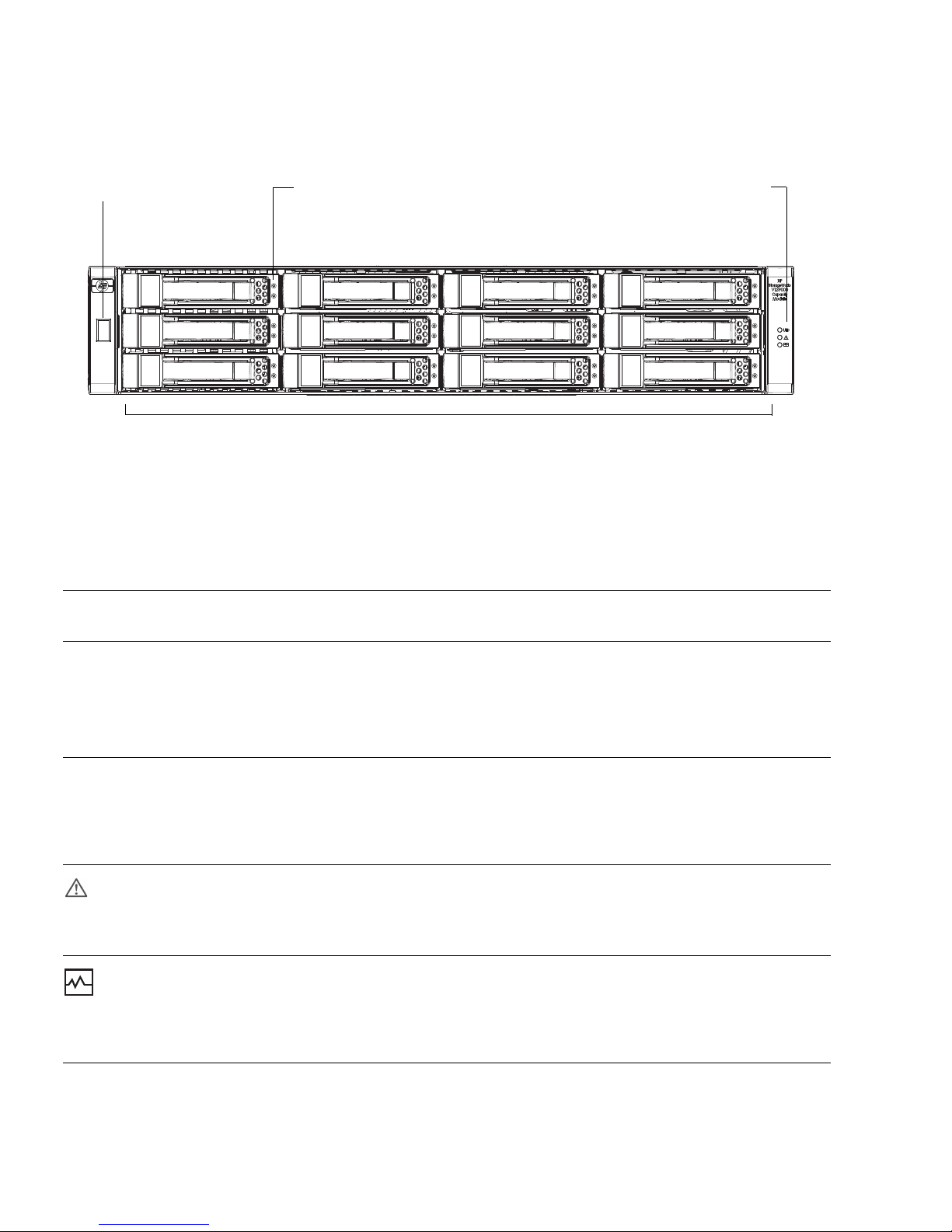
Figure 1-1 shows the LEDs on the front of a controller enclosure.
Figure 1-1 Controller Enclosure LEDs (Front View)
Table 1-2 describes the LEDs on the front of a controller. For information about
troubleshooting the system using LEDs, see “Troubleshooting” on page 53.
Table 1-2 Controller LEDs (Front)
LED Color
Operating
State Description
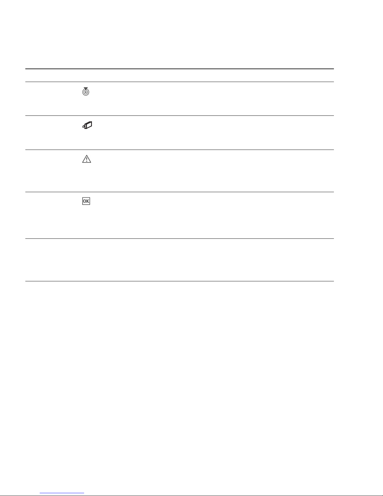
Enclosure ID Green On Shows the enclosure ID, which enables you to correlate an
enclosure with logical views presented by management
software. The enclosure ID for a controller enclosure is zero
(0); the enclosure ID for an attached drive enclosure is
nonzero.
UID
(Unit
Identification)
Blue On Identified.
Off Not identified.
Fault ID Amber Off No fault condition exists.
On Fault condition exists. The event has been acknowledged
but the problem needs attention. Service action is required.
Heartbeat Green On The enclosure is powered on with at least one power and
cooling module operating normally.
Off Both power and cooling modules are off; the system is
powered off.
Drive modules are numbered by column top to bottom: 0–2, 3–5, 6–8, 9–11
Drive module LEDs (top to bottom)Enclosure ID Status LEDs (top to bottom):
UID
Fault ID
Heartbeat
Fault/UID
Online/activity

Chapter 1 System Components 15
Table 1-3 describes the LEDs on the drive module.
Table 1-3 Drive Module LED Combinations (Front)
Online/Activity
(green)
Fault/UID
(amber/blue) Description
On Off The drive is online, but it is not currently active.
Blinking
irregularly
Off The drive is active and operating normally.
Off Amber, blinking
regularly (1 Hz)
Offline; the drive is not being accessed. A predictive
failure alert may have been received for this device.
Further investigation is required.
On Amber, blinking
regularly (1 Hz)
Online; no activity. A predictive failure alert may have
been received for this device. Further investigation is
required.
Blinking
irregularly
Amber, blinking
regularly (1 Hz)
The drive is active, but a predictive failure alert may
have been received for this drive. Further investigation
is required.
Off Amber, solid Offline; no activity. A critical fault condition has been
identified for this drive.
Off Blue; solid Offline. The drive has been selected by a management
application.
On or blinking Blue; solid The drive is operating normally, and it has been selected
by a management application.
Blinking regularly
(1 Hz)
Off Do not remove the drive. Removing a drive may
terminate the current operation and cause data loss.
The drive is rebuilding.
Off Off Either there is no power, the drive is offline, or the drive
is not configured.
16 HP StorageWorks 2012sa Modular Smart Array user guide • May 2008
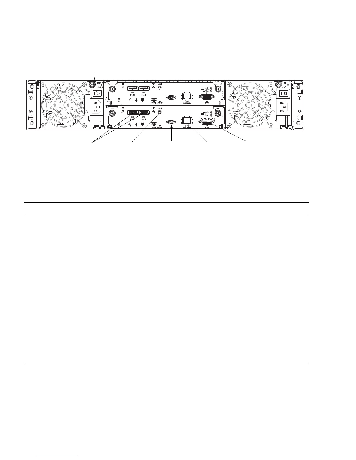
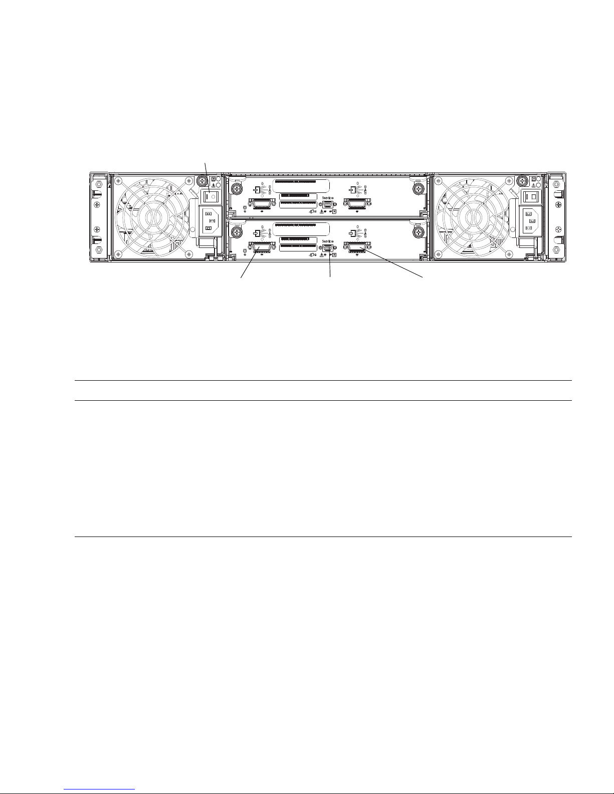
Figure 1-2 shows the ports and switches at the back of the controller enclosure.
Figure 1-2 Controller Ports and Switches (Back View)
Table 1-4 describes the ports and switches on the back of the controller.
Table 1-4 Controller Ports and Switches (Back)
Location Port/Switch Description
Power-andcooling module
Power switch On/Off toggle
Controller
module
Host ports 3-Gbps, 4-lane SAS ports (12 Gbps total) used to connect to data
hosts. Host port 0 and 1 correspond to host channel 0 and 1,
respectively.
Controller
module
Expansion
port
3-Gbps, 4-lane (12 Gbps total) table-routed SAS Out port used to
connect drive enclosures.
Controller
module
Ethernet port 10/100BASE-T Ethernet port used for TCP/IP-based out-of-band
management of the RAID controller. An internal Ethernet device
provides standard 10 Mbit/second and 100 Mbit/second full-duplex
connectivity.
Controller
module
CLI port Micro-DB9 port used to connect the controller enclosure to a local
management host using RS-232 communication for out-of-band
configuration and management.
Controller
module
MUI
(Service) port
3.5-mm jack port used by service personnel only.
Power switch
Host ports Expansion portCLI port Ethernet portMUI (Service) port
Chapter 1 System Components 17
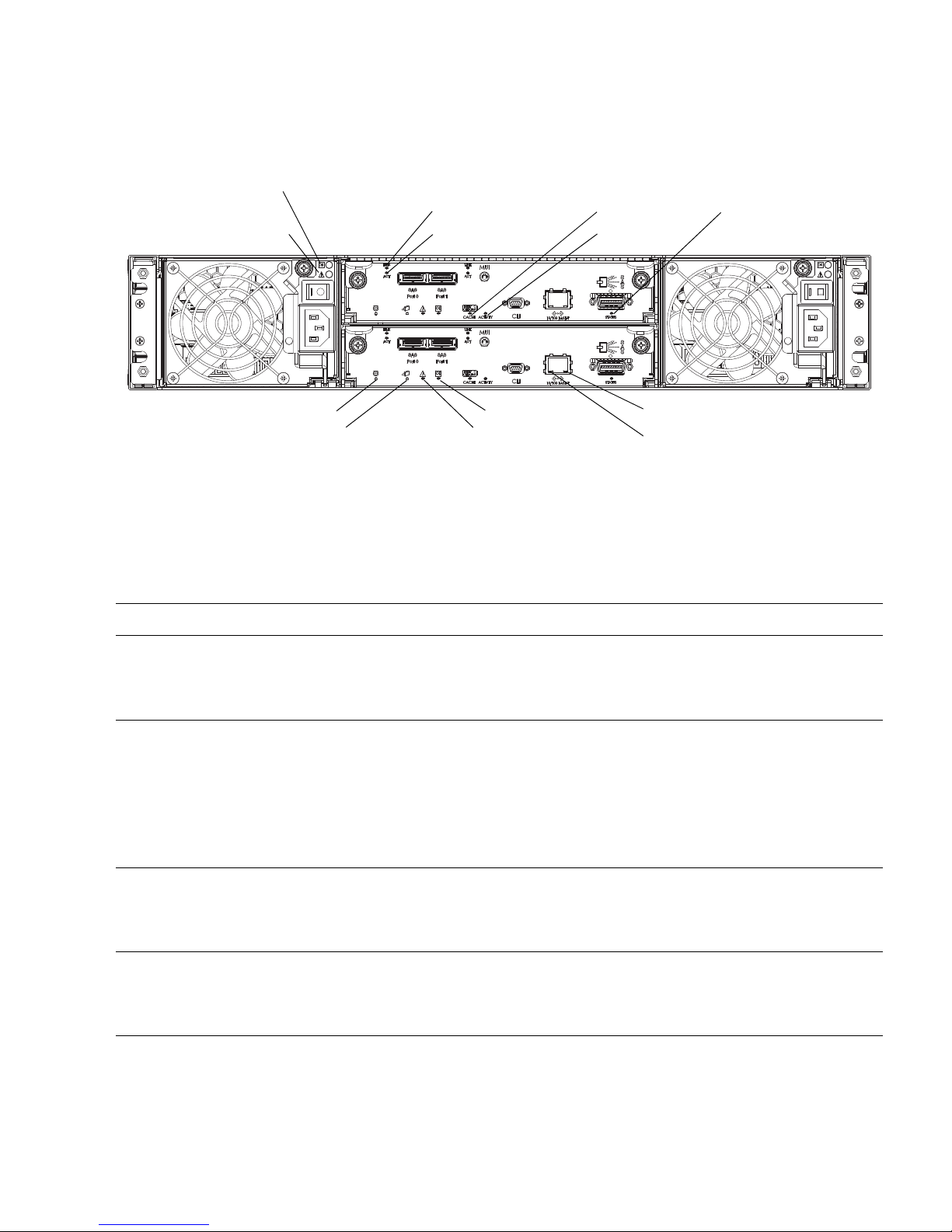
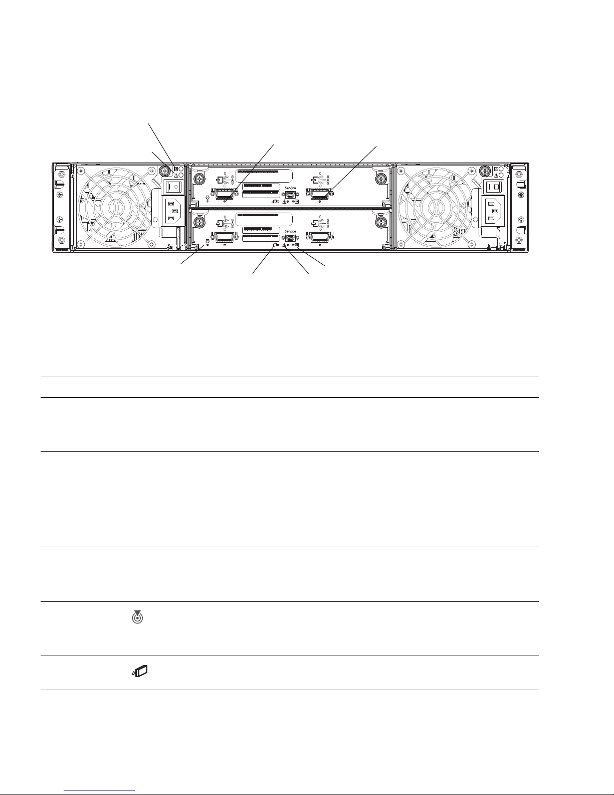
Figure 1-3 shows the LEDs at the back of the controller.
Figure 1-3 Controller LEDs (Back View)
Table 1-5 describes the LEDs on the back of the controller. For information about
troubleshooting the system using LEDs, see “Troubleshooting” on page 53.
Table 1-5 Controller LEDs (Back)
Location LED Color State Description
Power-andcooling module
AC Power Good Green Off AC power is off or input voltage is below
the minimum threshold.
On AC power is on and input voltage is normal.
Power-and
cooling module
DC Voltage/
Fan Fault/
Service Required
Amber Off DC output voltage is normal.
On DC output voltage is out of range or a fan is
operating below the minimum required
RPM.
Controller
module
Host link status Green Off The port is empty or the link is down.
On The port link is up and connected.
Controller
module
Host link activity Green Off The host port is not connected or the link is
down.
On The host link is up and active.
AC Power Good
Service Required
DC Voltage/Fan Fault/
Host link status
Host link activity
Unit Locator
OK to Remove Fault/Service Required
OK
Cache status
Host activity
Expansion port status
Ethernet activity
Ethernet link status
18 HP StorageWorks 2012sa Modular Smart Array user guide • May 2008
Controller
module
Unit Locator White Off Normal operation.
Blink Physically identifies the controller module.
Controller
module
OK to
Remove
Blue Off The controller module is not prepared for
removal.
On The controller module can be removed.
Controller
module
Fault/Service
Required
Amber On A fault has been detected or a service action
is required.
Blink Indicates a hardware-controlled power up or
a cache flush or restore error.
Controller
module
OK Green Off Controller module is not OK.
On Controller module is operating normally.
Blink System is booting.
Controller
module
Cache status Green Off Cache is clean (contains no unwritten data).
On Cache is dirty (contains unwritten data) and
operation is normal.
Table 1-5 Controller LEDs (Back) (Continued)
Location LED Color State Description

Chapter 1 System Components 19
Controller
module
Cache status Green Blink A Compact Flash flush or cache self-refresh
is in progress. Indicates cache activity.
• If the LED is blinking evenly, a cache
flush is in progress. When a controller
module loses power and write cache is
dirty (contains data that has not been
written to disk), the super-capacitor pack
provides backup power to flush (copy)
data from write cache to Compact Flash
memory. When cache flush is complete,
the cache transitions into self-refresh
mode.
• If the LED is blinking slowly, a cache
flush is in progress. In self-refresh mode,
if primary power is restored before the
backup power is depleted (3
–30 minutes,
depending on various factors), the system
boots, finds data preserved in cache, and
writes it to disk. This means the system
can be operational within 30 seconds, and
before the typical host I/O timeout of 60
seconds at which point system failure
would cause host-application failure. If
primary power is restored after the backup
power is depleted, the system boots and
restores data to cache from Compact
Flash, which can take about 90 seconds.
Note: The cache flush and self-refresh
mechanism is an important data protection
feature; essentially four copies of user data
are preserved: one in each controller’s cache
and one in each controller’s Compact Flash.
Controller
module
Host activity Green Off The host ports have no I/O activity.
Blink At least one host port has I/O activity.
Controller
module
Ethernet link status Green Off The Ethernet port is not connected or the
link is down.
On The Ethernet link is up.
Table 1-5 Controller LEDs (Back) (Continued)
Location LED Color State Description

20 HP StorageWorks 2012sa Modular Smart Array user guide • May 2008
Drive Enclosure Components and LEDs
A drive enclosure can be connected to a controller enclosure or to another drive
enclosure to provide additional disk storage capacity. Table 1-6 describes the drive
enclosure components.
Controller
module
Ethernet activity Green Off The Ethernet link has no I/O activity.
Blink The Ethernet link has I/O activity.
Controller
module
Expansion port
status
Green Off The port is empty or the link is down.
On The port link is up and connected.
Table 1-6 Drive Enclosure Components
Description Quantity
Expansion (I/O) module 1 or 2
1
1 Air-management system drive blanks or I/O blanks must fill empty slots to maintain optimum airflow through the chassis.
SAS or SATA drive module 2–12 per enclosure
AC power-and-cooling module 2 per enclosure
3-Gbps, 4-lane SAS In port 1 per expansion module
3-Gbps, 4-lane SAS Out port 1 per expansion module
Service port (RS-232 micro-DB9) 1 per expansion module
Table 1-5 Controller LEDs (Back) (Continued)
Location LED Color State Description
Chapter 1 System Components 21
The components and LEDs on the front of a drive enclosure are the same as on a
controller enclosure; see Figure 1-1 and Table 1-2.
Figure 1-4 shows the ports and switches at the back of the drive enclosure.
Figure 1-4 Drive Enclosure Ports and Switches (Back View)
Table 1-7 describes the ports and switches on the back of the drive enclosure.
Table 1-7 Drive Enclosure Ports and Switches (Back)
Location Port/Switch Description
Power-andcooling module
Power switch On/Off toggle
Expansion
module
SAS In port 3-Gbps, 4-lane (12 Gbps total) subtractive ingress port used to
connect to a controller enclosure.
Expansion
module
SAS Out port 3-Gbps, 4-lane (12 Gbps total) table-routed egress port used to
connect to another drive enclosure.
Expansion
module
Service port Micro-DB9 port used by service personnel only.
Service port SAS Out port
Power switch
SAS In port
22 HP StorageWorks 2012sa Modular Smart Array user guide • May 2008
Figure 1-5 shows the LEDs at the back of the drive enclosure.
Figure 1-5 Drive Enclosure LEDs (Back View)
Table 1-8 describes the LEDs on the back of the drive enclosure.
Table 1-8 Drive Enclosure LEDs (Back)
Location LED Color State Description
Power-andcooling module
AC Power Good Green Off AC power is off or input voltage is below
the minimum threshold.
On AC power is on and input voltage is normal.
Power -andcooling module
DC Voltage/
Fan Fault/
Service Required
Amber Off DC output voltage is normal.
On DC output voltage is out of range or a fan is
operating below the minimum required
RPM.
Expansion
module
SAS In port status Green Off The port is empty or the link is down.
On The port link is up and connected.
Expansion
module
Unit Locator White Off Normal operation.
Blink Physically identifies the expansion module.
Expansion
module
OK to
Remove
Not implemented.
AC Power Good
Service Required
DC Voltage/Fan Fault/
SAS In port status SAS Out port status
Unit Locator
OK to Remove
Fault/Service Required
OK
Chapter 1 System Components 23
Expansion
module
Fault/Service
Required
Amber On A fault has been detected or a service action
is required.
Blink Indicates a hardware-controlled power up or
a cache flush or restore error.
Expansion
module
OK Green Off Expansion module is not OK.
On Expansion module is operating normally.
Blink System is booting.
Expansion
module
SAS Out port
status
Green Off The port is empty or the link is down.
On The port link is up and connected.
Table 1-8 Drive Enclosure LEDs (Back) (Continued)
Location LED Color State Description

24 HP StorageWorks 2012sa Modular Smart Array user guide • May 2008

25
CHAPTER
2
Installing and Cabling Enclosures
This chapter describes how to install and cable enclosures. It contains the following
sections:
■ “Site Planning” on page 25
■ “Required Tools” on page 25
■ “Safety Precautions” on page 26
■ “Installation Checklist” on page 27
■ “Installing Enclosures Into a Rack” on page 28
■ “Attaching the Ear Caps” on page 32
■ “Connecting Controller and Drive Enclosures” on page 33
■ “Connecting AC Power” on page 36
■ “Testing the Enclosure Connections” on page 37
■ “Obtaining IP Values for Your Storage System” on page 38
■ “Correcting Enclosure IDs” on page 38
Site Planning
Make sure that the installation site adheres to all requirements and specifications as
described in “Environmental Requirements and Specifications” on page 71.
Required Tools
The installation procedures in this chapter require the following tools:
■ #2 Phillips screwdriver
■ Antistatic protection devices
26 HP StorageWorks 2012sa Modular Smart Array user guide • May 2008
Safety Precautions
For your protection, observe the following safety precautions when setting up your
equipment:
■ Install the system in accordance with the local safety codes and regulations at the
facility site. Follow all cautions and instructions marked on the equipment.
■ Ensure that the voltage and frequency of your power source match the voltage
and frequency inscribed on the equipment’s electrical rating label.
■ Never push objects of any kind through openings in the equipment. Dangerous
voltages may be present. Conductive foreign objects could produce a short circuit
that could cause fire, electric shock, or damage to your equipment.
Note – Do not make mechanical or electrical modifications to the product. The
vendor is not responsible for the safety or regulatory compliance of a modified
product.
Caution – Two people are needed to lift and move the enclosure. Use care to avoid
injury. An enclosure with all drives installed can weigh 65 pounds (29.5 kilograms).
Caution – Electrostatic discharge can damage sensitive components. Be sure you
are properly grounded before touching a static-sensitive component or assembly.

Chapter 2 Installing and Cabling Enclosures 27
Installation Checklist
Table 2-1 outlines the steps required to install the enclosures and initially configure
the system. To ensure a successful installation, perform the tasks in the order they
are presented.
Table 2-1 Installation Checklist
Step Installation Task Where to Find Procedure
1. Prepare the rack for installation. “Preparing the Rack” on page 28
2. Assemble the rackmount bracket kit and install the
controller enclosure and optional drive enclosures in
the rack.
“Assembling and Installing the
Rackmount Bracket Kit” on page 28
3. Attach the ear caps. “Attaching the Ear Caps” on page 32
4. Connect the enclosures. “Connecting Controller and Drive
Enclosures” on page 33
5. Connect the power cords. “Connecting AC Power” on page 36
6. Test the enclosure connections. “Testing the Enclosure Connections” on
page 37
7. Obtain IP values. “Obtaining IP Values for Your Storage
System” on page 38
8. Correct enclosure IDs, if necessary. “Correcting Enclosure IDs” on page 38
9. Install required host software and drivers, including:
• MSA2000 Family MPIO DSM
• MSA2000 Family SES Driver
“Host System Requirements” on page 39
10. Connect the data hosts. “Connecting Hosts” on page 39
11. Connect the management host. “Connecting Remote Management
Hosts” on page 40
12. Perform initial configuration tasks:
• Set management port IP properties on the
controller enclosure
• Verify that controllers and enclosures have the
latest firmware
• Set the date and time on the controller enclosure
• Configure host ports on the controller enclosure
• Create virtual disks and map volumes
• Test the configuration
“Configuring a System for the First
Time” on page 41

28 HP StorageWorks 2012sa Modular Smart Array user guide • May 2008
Installing Enclosures Into a Rack
This section describes how to install the enclosures into a standard 19-inch rack
cabinet with a 28 to 36-inch (71.12 to 91.44-cm) depth.
Tip – To help you correctly identify the screws, keep all hardware items in plastic
bags until you are ready to use them.
Preparing the Rack
Before installing enclosures in a rack cabinet, ensure the rack is installed according
to its installation instructions and that the installation complies with local safety
codes.
1. Stabilize the rack as described in its documentation.
2. If the rack has casters, make sure the casters are locked to prevent the rack from
rolling.
3. Remove or open the top front panel and the vented back panel.
Assembling and Installing the Rackmount Bracket
Kit
Note – If the rackmount bracket kit you are installing includes assembly
instructions, use them in place of the instructions in this guide.
Chapter 2 Installing and Cabling Enclosures 29
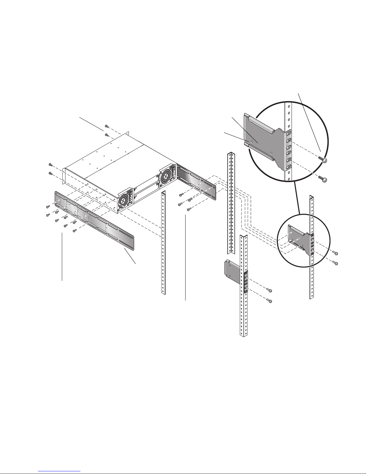
Figure 2-1 provides a visual overview of the rackmount kit assembly components
and corresponds to the steps that follow.
Figure 2-1 Overview of Standard 19-Inch EIA Rackmounting Components
#10-32 x 5/8 truss screws
Threaded PEMs (4)
Rear bracket connected to rack
#10-32 x 5/8 truss screws
Side bracket
(Step 6)
(Step 5)
(Step 8)
(Step 9)
#8-32 x 3/16 flathead screws
#8-32 x 1/4 panhead screws

30 HP StorageWorks 2012sa Modular Smart Array user guide • May 2008
Use the following procedure and refer to Figure 2-1 to install each enclosure into
the rack.
Note – If the rackmount bracket kit you are installing includes assembly
instructions, use them in place of the instructions in this guide.
When positioning an enclosure in the rack, do not block the air vents at the front or
back of the enclosure.
Caution – If you only have one person to perform the installation, remove the
power and cooling modules and drive modules from an enclosure before
installation, and use the optional nylon front support brackets. If possible, position
the enclosure on top of another device or shelf in the rack to hold the enclosure as
you attach the front brackets.
1. Considering your system configuration and weight distribution in the rack,
determine where you will install each enclosure in the rack.
2. Confirm that you have cables of adequate length to connect to hosts and to power
outlets.
3. (Square-cut European-style racks only) Insert the cage nuts in the corresponding
holes on the front and rear of the rack.
4. (Optional-one person installation) Screw the front support nylon brackets into
position on the rack face using #10-32 x 5/8 screws (two per bracket).
These brackets enable one person to easily position and support the front of the
enclosure in the rack during installation.
5. Attach the side brackets to each side of the enclosure using #8-32 x 3/16 flathead
screws (four to eight on each side). The right and left side brackets are identical.
Note – To allow adjustment of the brackets, do not tighten the screws completely
until the enclosure is mounted in the rack.
a. Use the alignment marks (Figure 2-2) stamped into the side brackets to position
the brackets and screws. The alignment marks show depth in inches.
Determine the depth you require and align the rear-most alignment mark on the
side bracket with the rear-most threaded holes on the enclosure. Make sure that
the alignment mark corresponding to the depth you want lines up with both the
top and bottom holes.
 Loading...