

Page 1
HP StorageWorks
Cable information
Carrier-Grade Enclosure
installation instructions
This document provides specific information regarding
the carrier-grade versions of the HP StorageWorks
Dual I/O 2.5" DC-power Drive Enclosure.
This section provides cabling information for installing the HP
StorageWorks Dual I/O 2.5" DC-power Drive Enclosure.
NOTE:
This carrier-grade product is intended for use in both common
bonding networks and isolated bonding networks.
NEBS chassis ground
There are two grounding methods that can be used when installing the
HP StorageWorks Dual I/O 2.5" DC-power Drive Enclosure:
• Using a single wire coming from the front of the chassis ears
• Using a cable from the power supply
Installation and grounding instructions — single wire method
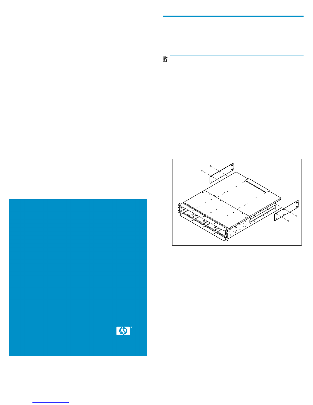
1. Attach the rear brackets to the Carrier-Grade Enclosure.
© Copyright 1999, 2009 Hewlett-Packard Development Company,
L.P.
First edition: October 2009
The information in this document is subject to change without notice.
Printed in the US
www.hp.com
2. Attach the left bracket assembly to the left rack rail.
3. Attach the right bracket assembly to the right rack rail.
4. Insert cage nuts into the rack holes.
5. Align the Carrier-Grade Enclosure with the rails, and then slide it
into the rack until the ears of the enclosure are about 1 to 2 inches
from the rack front rails.
6. Attach a flat washer between the right mounting ear (bottom hole)
and the rack, and then loosely attach the bracket to the rear bracket
assemblies.
*589728-001*
Page 1
Page 2
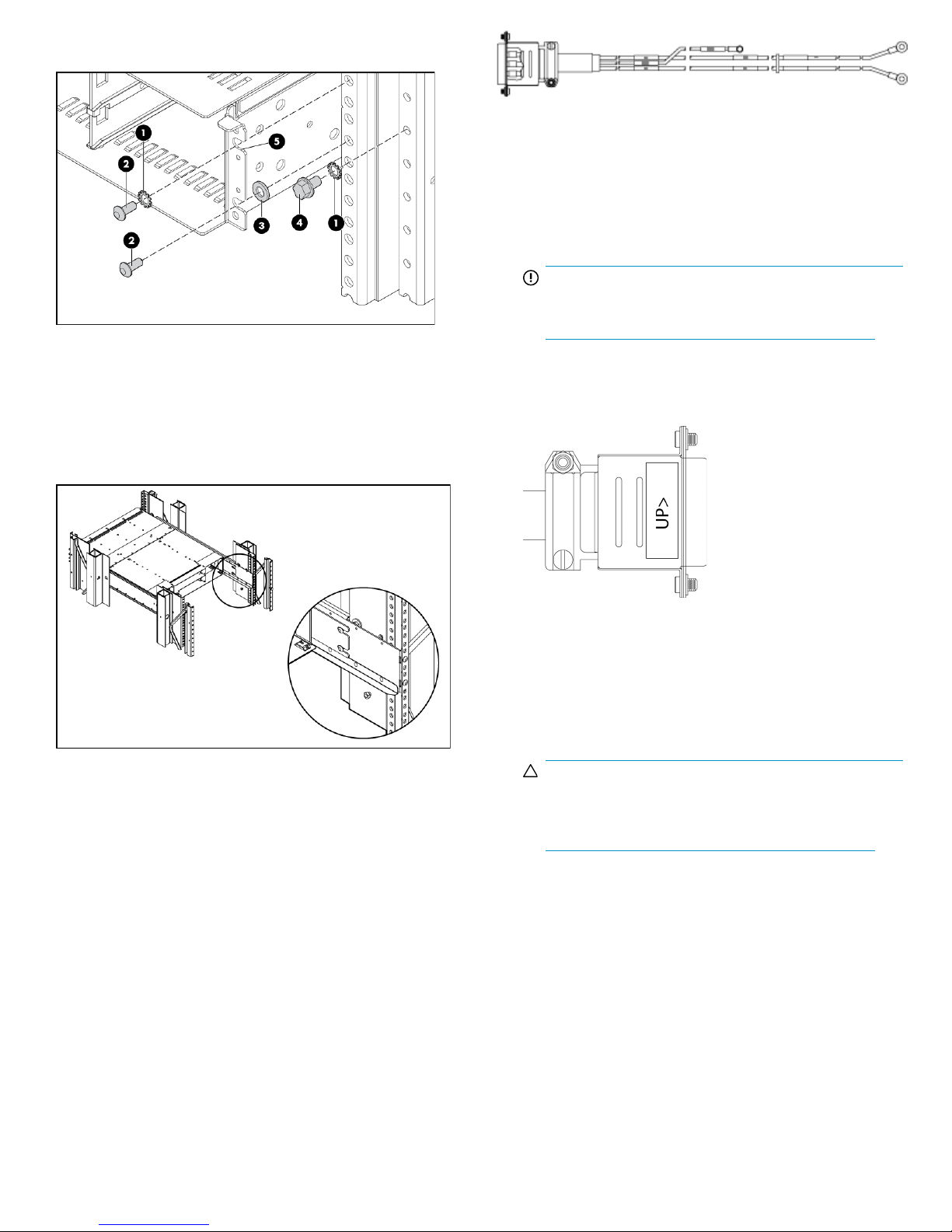
7. Attach the single-hole ground cable lug between the front right
mounting ear (top hole) and the rack with a lock washer and screw.
1. Lock washer
2. Screw
3. Flat washer
4. Bolt
5. Ground cable lug. Position between ear and rail (cable not
shown).
8. Loosely attach the rear brackets to the rear bracket assemblies.
Figure 1 DC power cable with D-Shell connector for connecting to a
power-and-cooling module and three lugs for connecting to a DC power
supply
.
1. Verify that both power switches are off.
2. Check the DC cable part numbers and wire labels carefully before
connecting the cable to the source.
IMPORTANT:
One wire is labeled as ground; the other two are
labeled as positive and negative.
3. Connect a DC power cable to the first power-and-cooling module,
using the D-shell connector. Use the up arrow on the shell to ensure
proper positioning before tightening.
9. Attach the loose end of the ground cable to the front rack ground
rail.
10. Verify that the Carrier-Grade Enclosure is evenly spaced between
the right and left rack rails, and then tighten the front and rear
bracket screws.
Installation and grounding instructions — power supply cable
method
Two DC power cables are packaged with each disk enclosure. Use only
the DC power cables provided.
Site wiring must include an earth ground connection to the DC power
source. Grounding must comply with local, national, or other applicable
government codes and regulations.
Figure 2 Power cable shell with up arrow
.
4. Tighten the screws at the top and bottom of the shell with a torque
between 1.7 N-m (15 lb-in) and 2.3 N-m (20 lb-in) to attach the
cable securely to the power-and-cooling module.
5. Securely connect the other end of the DC power cable to a DC
power source.
CAUTION:
If the enclosure is connected to DC power sources that
are not within the designated –48V DC nominal (–36
VDC to –72 VDC) range, it might be damaged.
6. Connect the wire labeled Ground to an appropriate earth ground.
7. Using the instructions above, connect the second DC power cable
to the other power-and cooling-module and to a DC power source.
If one power-and-cooling module fails, the second power-and-cooling
module automatically takes the full load.
8. Power on the system as described in the following section.
Gigabit Ethernet port cabling
Gigabit Ethernet Ports (intra-building ports) of the HP StorageWorks
Carrier-Grade Enclosure require the use of shielded Ethernet cables
grounded at both ends. Furthermore, please note the following:
Page 2
Page 3

CAUTION:
The intra-building ports of the equipment are suitable for
connection to intra-building or unexposed wiring or cabling
only. The intra-building ports of the equipment MUST NOT be
metallically connected to interfaces that connect to the Outside
Plant (OSP) or its wiring. These interfaces are designed for use
as intra-building interfaces only (Type 2 or Type 4 ports as
described in GR-1089-CORE, Issue 4) and require isolation
from the exposed OSP cabling. The addition of primary
protectors is not sufficient protection in order to connect these
interfaces metallically to OSP wiring.
Power supply information
Operation environmental specifications
• Nominal Input Voltage: -48VDC
• Rated Input Voltage: -40 VDC to -75 VDC
• Rated Input Current: 10.4A
• Rated Input Power: 500W
• Power load (single line, both lines powered): 220 watts per line,
441 watts total
• Power load (single line, one line powered): 432 watts
• Peak inrush current: 30 amps (specification limit)
• Battery Return Terminals are Isolated DC Returns (DC-I)
NOTE:
For more information on static electricity, or assistance with
product installation, contact your HP authorized reseller.
Replacing the power supply
In the event a power supply or its internal cooling fan fail, it must be
replaced. This should take approximately 5 minutes.
For instructions on replacing the power supply see the HP StorageWorks
2312/2324 Modular Smart Array DC power supply replacement
instructions, part number 500919-001. This document is provided with
the replacement DC power supply and can also be found at h
www.hp.com/support/manuals. Under Storage, click Disk Storage
Systems, and select your product.
ttp://
Preventing electrostatic discharge
To prevent damaging the system, be aware of the precautions you need
to follow when setting up the system or handling parts. A discharge of
static electricity from a finger or other conductor may damage system
boards or other static-sensitive devices. This type of damage may reduce
the life expectancy of the device.
To prevent electrostatic damage:
• Avoid hand contact by transporting and storing products in static-
safe containers.
• Keep electrostatic-sensitive parts in their containers until they arrive
at static-free workstations.
• Place parts on a grounded surface before removing them from their
containers.
• Avoid touching pins, leads, or circuitry.
• Always be properly grounded when touching a static-sensitive com-
ponent or assembly.
Page 3
 Loading...