

Page 1

HP StorageWorks Simple SAN Connection
Manager user guide
Part number: 5697-0083
Fifth edition: July 2009
Page 2

Legal and notice information
© Copyright 2008–2009 Hewlett-Packard Development Company, L.P.
Confidential computer software. Valid license from HP required for possession, use or copying. Consistent with FAR 12.211 and 12.212, Commercial
Computer Software, Computer Software Documentation, and Technical Data for Commercial Items are licensed to the U.S. Government under
vendor's standard commercial license.
The information contained herein is subject to change without notice. The only warranties for HP products and services are set forth in the express
warranty statements accompanying such products and services. Nothing herein should be construed as constituting an additional warranty. HP shall
not be liable for technical or editorial errors or omissions contained herein.
Microsoft, Windows, Windows Server 2003, Windows Server 2008, and Internet Explorer are registered trademarks of Microsoft Corporation in
the United States and other countries.
Linux is the registered trademark of Linus Torvalds in the U.S. and other countries.
Java Runtime Environment (JRE) is a trademark of Sun Microsystems, Inc. in the United States and other countries.
Mozilla Firefox and Netscape Navigator are registered trademarks of Netscape Communications Corporation in the United States and other
countries.
Emulex and HBAnywhere are registered trademarks of Emulex Corporation.
QuickTools is a trademark of QLogic Corporation.
HP StorageWorks Simple SAN Connection Manager user guide
Page 3

Contents
About this guide. . . . . . . . . . . . . . . . . . . . . . . . . . . . . . . . . . . . . . . . . . . . . . . . . . . . . . . 9
Intended audience . . . . . . . . . . . . . . . . . . . . . . . . . . . . . . . . . . . . . . . . . . . . . . . . . . . . . . . . . . . . . . . 9
Prerequisites. . . . . . . . . . . . . . . . . . . . . . . . . . . . . . . . . . . . . . . . . . . . . . . . . . . . . . . . . . . . . . . . . . . . 9
Related documentation . . . . . . . . . . . . . . . . . . . . . . . . . . . . . . . . . . . . . . . . . . . . . . . . . . . . . . . . . . . . 9
Document conventions and symbols . . . . . . . . . . . . . . . . . . . . . . . . . . . . . . . . . . . . . . . . . . . . . . . . . . 10
HP technical support . . . . . . . . . . . . . . . . . . . . . . . . . . . . . . . . . . . . . . . . . . . . . . . . . . . . . . . . . . . . . 10
Product warranties . . . . . . . . . . . . . . . . . . . . . . . . . . . . . . . . . . . . . . . . . . . . . . . . . . . . . . . . . . . . . . 11
Subscription service . . . . . . . . . . . . . . . . . . . . . . . . . . . . . . . . . . . . . . . . . . . . . . . . . . . . . . . . . . . . . 11
HP websites . . . . . . . . . . . . . . . . . . . . . . . . . . . . . . . . . . . . . . . . . . . . . . . . . . . . . . . . . . . . . . . . . . . 11
Documentation feedback . . . . . . . . . . . . . . . . . . . . . . . . . . . . . . . . . . . . . . . . . . . . . . . . . . . . . . . . . . 11
1 Introduction . . . . . . . . . . . . . . . . . . . . . . . . . . . . . . . . . . . . . . . . . . . . . . . . . . . . . . . 13
What’s in this guide . . . . . . . . . . . . . . . . . . . . . . . . . . . . . . . . . . . . . . . . . . . . . . . . . . . . . . . . . . . . . 13
What’s new in this release . . . . . . . . . . . . . . . . . . . . . . . . . . . . . . . . . . . . . . . . . . . . . . . . . . . . . . . . . 14
System requirements . . . . . . . . . . . . . . . . . . . . . . . . . . . . . . . . . . . . . . . . . . . . . . . . . . . . . . . . . . . . . 14
2 Installing, upgrading, and removing Simple SAN Connection Manager . . . . . . . . . . . . . 15
Installing Simple SAN Connection Manager: initial installation. . . . . . . . . . . . . . . . . . . . . . . . . . . . . . . . 15
Windows installation: initial . . . . . . . . . . . . . . . . . . . . . . . . . . . . . . . . . . . . . . . . . . . . . . . . . . . . . 15
Linux installation: initial . . . . . . . . . . . . . . . . . . . . . . . . . . . . . . . . . . . . . . . . . . . . . . . . . . . . . . . . 18
Configuring Simple SAN Connection Manager for HP-UX and Emulex HBAs . . . . . . . . . . . . . . . . . . . . . . 20
HP-UX configuration . . . . . . . . . . . . . . . . . . . . . . . . . . . . . . . . . . . . . . . . . . . . . . . . . . . . . . . . . . . 20
Emulex HBA configuration . . . . . . . . . . . . . . . . . . . . . . . . . . . . . . . . . . . . . . . . . . . . . . . . . . . . . . 21
Installing Simple SAN Connection Manager: upgrade installation. . . . . . . . . . . . . . . . . . . . . . . . . . . . . . 21
Windows installation: upgrade . . . . . . . . . . . . . . . . . . . . . . . . . . . . . . . . . . . . . . . . . . . . . . . . . . . 21
Linux installation: upgrade . . . . . . . . . . . . . . . . . . . . . . . . . . . . . . . . . . . . . . . . . . . . . . . . . . . . . . 24
Removing Simple SAN Connection Manager . . . . . . . . . . . . . . . . . . . . . . . . . . . . . . . . . . . . . . . . . . . . 26
Removing Simple SAN Connection Manager in Windows . . . . . . . . . . . . . . . . . . . . . . . . . . . . . . . . 26
Removing Simple SAN Connection Manager in Linux. . . . . . . . . . . . . . . . . . . . . . . . . . . . . . . . . . . . 27
3 Getting started . . . . . . . . . . . . . . . . . . . . . . . . . . . . . . . . . . . . . . . . . . . . . . . . . . . . . 29
Understanding the user interface . . . . . . . . . . . . . . . . . . . . . . . . . . . . . . . . . . . . . . . . . . . . . . . . . . . . 29
Application window. . . . . . . . . . . . . . . . . . . . . . . . . . . . . . . . . . . . . . . . . . . . . . . . . . . . . . . . . . . 29
Menu bar . . . . . . . . . . . . . . . . . . . . . . . . . . . . . . . . . . . . . . . . . . . . . . . . . . . . . . . . . . . . . . . . . . 30
File menu . . . . . . . . . . . . . . . . . . . . . . . . . . . . . . . . . . . . . . . . . . . . . . . . . . . . . . . . . . . . . . . . 31
Logical Disk Operations menu . . . . . . . . . . . . . . . . . . . . . . . . . . . . . . . . . . . . . . . . . . . . . . . . . 31
Advanced Operations menu. . . . . . . . . . . . . . . . . . . . . . . . . . . . . . . . . . . . . . . . . . . . . . . . . . . 32
HBA & Switch Management menu . . . . . . . . . . . . . . . . . . . . . . . . . . . . . . . . . . . . . . . . . . . . . . 32
Help menu . . . . . . . . . . . . . . . . . . . . . . . . . . . . . . . . . . . . . . . . . . . . . . . . . . . . . . . . . . . . . . . 33
Toolbar . . . . . . . . . . . . . . . . . . . . . . . . . . . . . . . . . . . . . . . . . . . . . . . . . . . . . . . . . . . . . . . . . . . 33
Using the help system . . . . . . . . . . . . . . . . . . . . . . . . . . . . . . . . . . . . . . . . . . . . . . . . . . . . . . . . . . . . 34
Starting Simple SAN Connection Manager . . . . . . . . . . . . . . . . . . . . . . . . . . . . . . . . . . . . . . . . . . . . . 35
4 Viewing maps, events, and configurations. . . . . . . . . . . . . . . . . . . . . . . . . . . . . . . . . . 43
Viewing a Physical Connection map . . . . . . . . . . . . . . . . . . . . . . . . . . . . . . . . . . . . . . . . . . . . . . . . . . 43
Description of a Physical Connection map . . . . . . . . . . . . . . . . . . . . . . . . . . . . . . . . . . . . . . . . . . . 43
How to view a Physical Connection map . . . . . . . . . . . . . . . . . . . . . . . . . . . . . . . . . . . . . . . . . . . . 44
Viewing a LUN Assignment map . . . . . . . . . . . . . . . . . . . . . . . . . . . . . . . . . . . . . . . . . . . . . . . . . . . . 44
Description of a LUN Assignment map . . . . . . . . . . . . . . . . . . . . . . . . . . . . . . . . . . . . . . . . . . . . . . 44
How to view a LUN Assignment map . . . . . . . . . . . . . . . . . . . . . . . . . . . . . . . . . . . . . . . . . . . . . . . 44
Viewing the event log . . . . . . . . . . . . . . . . . . . . . . . . . . . . . . . . . . . . . . . . . . . . . . . . . . . . . . . . . . . . 45
Saving and comparing SAN configurations . . . . . . . . . . . . . . . . . . . . . . . . . . . . . . . . . . . . . . . . . . . . . 46
Saving the current configuration . . . . . . . . . . . . . . . . . . . . . . . . . . . . . . . . . . . . . . . . . . . . . . . . . . 46
Comparing configurations . . . . . . . . . . . . . . . . . . . . . . . . . . . . . . . . . . . . . . . . . . . . . . . . . . . . . . 46
HP StorageWorks Simple SAN Connection Manager user guide 3
Page 4

5 Managing switches . . . . . . . . . . . . . . . . . . . . . . . . . . . . . . . . . . . . . . . . . . . . . . . . . 49
About transparent routing . . . . . . . . . . . . . . . . . . . . . . . . . . . . . . . . . . . . . . . . . . . . . . . . . . . . . . . . . 49
Viewing switch properties . . . . . . . . . . . . . . . . . . . . . . . . . . . . . . . . . . . . . . . . . . . . . . . . . . . . . . . . . 49
Description of the switch properties . . . . . . . . . . . . . . . . . . . . . . . . . . . . . . . . . . . . . . . . . . . . . . . . 49
How to view switch properties. . . . . . . . . . . . . . . . . . . . . . . . . . . . . . . . . . . . . . . . . . . . . . . . . . . . 50
Viewing network properties . . . . . . . . . . . . . . . . . . . . . . . . . . . . . . . . . . . . . . . . . . . . . . . . . . . . . . . . 50
Description of the network properties . . . . . . . . . . . . . . . . . . . . . . . . . . . . . . . . . . . . . . . . . . . . . . . 50
How to view network properties . . . . . . . . . . . . . . . . . . . . . . . . . . . . . . . . . . . . . . . . . . . . . . . . . . 51
Viewing switch zoning information . . . . . . . . . . . . . . . . . . . . . . . . . . . . . . . . . . . . . . . . . . . . . . . . . . . 51
Setting the switch default zoning . . . . . . . . . . . . . . . . . . . . . . . . . . . . . . . . . . . . . . . . . . . . . . . . . . . . 53
Setting the switch admin password . . . . . . . . . . . . . . . . . . . . . . . . . . . . . . . . . . . . . . . . . . . . . . . . . . . 55
Setting the switch IP address . . . . . . . . . . . . . . . . . . . . . . . . . . . . . . . . . . . . . . . . . . . . . . . . . . . . . . . 55
Updating switch firmware . . . . . . . . . . . . . . . . . . . . . . . . . . . . . . . . . . . . . . . . . . . . . . . . . . . . . . . . . 57
Setting switch SNMP properties . . . . . . . . . . . . . . . . . . . . . . . . . . . . . . . . . . . . . . . . . . . . . . . . . . . . . 59
Setting the switch symbolic name and domain ID . . . . . . . . . . . . . . . . . . . . . . . . . . . . . . . . . . . . . . . . . 62
Setting DNS properties . . . . . . . . . . . . . . . . . . . . . . . . . . . . . . . . . . . . . . . . . . . . . . . . . . . . . . . . . . . 62
Setting switch IP security . . . . . . . . . . . . . . . . . . . . . . . . . . . . . . . . . . . . . . . . . . . . . . . . . . . . . . . . . . 64
Managing security associations. . . . . . . . . . . . . . . . . . . . . . . . . . . . . . . . . . . . . . . . . . . . . . . . . . . 64
Creating an IPsec association. . . . . . . . . . . . . . . . . . . . . . . . . . . . . . . . . . . . . . . . . . . . . . . . . . 65
Editing an IPsec association . . . . . . . . . . . . . . . . . . . . . . . . . . . . . . . . . . . . . . . . . . . . . . . . . . . 68
Deleting an IPsec association . . . . . . . . . . . . . . . . . . . . . . . . . . . . . . . . . . . . . . . . . . . . . . . . . . 68
Copying and pasting IPsec associations . . . . . . . . . . . . . . . . . . . . . . . . . . . . . . . . . . . . . . . . . . 68
Managing security policies . . . . . . . . . . . . . . . . . . . . . . . . . . . . . . . . . . . . . . . . . . . . . . . . . . . . . . 69
Creating an IPsec policy . . . . . . . . . . . . . . . . . . . . . . . . . . . . . . . . . . . . . . . . . . . . . . . . . . . . . 70
Editing an IPsec policy. . . . . . . . . . . . . . . . . . . . . . . . . . . . . . . . . . . . . . . . . . . . . . . . . . . . . . . 73
Deleting an IPsec policy. . . . . . . . . . . . . . . . . . . . . . . . . . . . . . . . . . . . . . . . . . . . . . . . . . . . . . 73
Copying and pasting IPsec polices . . . . . . . . . . . . . . . . . . . . . . . . . . . . . . . . . . . . . . . . . . . . . . 74
6 Managing HBAs . . . . . . . . . . . . . . . . . . . . . . . . . . . . . . . . . . . . . . . . . . . . . . . . . . . 75
Viewing HBA information . . . . . . . . . . . . . . . . . . . . . . . . . . . . . . . . . . . . . . . . . . . . . . . . . . . . . . . . . 75
Updating an HBA BIOS image. . . . . . . . . . . . . . . . . . . . . . . . . . . . . . . . . . . . . . . . . . . . . . . . . . . . . . 76
Updating an HBA driver . . . . . . . . . . . . . . . . . . . . . . . . . . . . . . . . . . . . . . . . . . . . . . . . . . . . . . . . . . 78
Creating an alias for an HBA. . . . . . . . . . . . . . . . . . . . . . . . . . . . . . . . . . . . . . . . . . . . . . . . . . . . . . . 80
Manually entering FDMI information . . . . . . . . . . . . . . . . . . . . . . . . . . . . . . . . . . . . . . . . . . . . . . . . . . 81
7 Managing logical disks (LUNs) . . . . . . . . . . . . . . . . . . . . . . . . . . . . . . . . . . . . . . . . . 83
Viewing logical disk information. . . . . . . . . . . . . . . . . . . . . . . . . . . . . . . . . . . . . . . . . . . . . . . . . . . . . 83
Creating a logical disk—EVA storage . . . . . . . . . . . . . . . . . . . . . . . . . . . . . . . . . . . . . . . . . . . . . . . . . 84
Creating a logical disk—MSA storage . . . . . . . . . . . . . . . . . . . . . . . . . . . . . . . . . . . . . . . . . . . . . . . . 88
Assigning and unassigning a logical disk to a server . . . . . . . . . . . . . . . . . . . . . . . . . . . . . . . . . . . . . . 95
Expanding a logical disk . . . . . . . . . . . . . . . . . . . . . . . . . . . . . . . . . . . . . . . . . . . . . . . . . . . . . . . . . . 97
Deleting a logical disk. . . . . . . . . . . . . . . . . . . . . . . . . . . . . . . . . . . . . . . . . . . . . . . . . . . . . . . . . . . . 98
Creating an alias for a logical disk . . . . . . . . . . . . . . . . . . . . . . . . . . . . . . . . . . . . . . . . . . . . . . . . . . . 99
8 Managing servers . . . . . . . . . . . . . . . . . . . . . . . . . . . . . . . . . . . . . . . . . . . . . . . . . 101
Viewing server information . . . . . . . . . . . . . . . . . . . . . . . . . . . . . . . . . . . . . . . . . . . . . . . . . . . . . . . 101
Refreshing the server list . . . . . . . . . . . . . . . . . . . . . . . . . . . . . . . . . . . . . . . . . . . . . . . . . . . . . . . . . 103
Setting a server agent password. . . . . . . . . . . . . . . . . . . . . . . . . . . . . . . . . . . . . . . . . . . . . . . . . . . . 104
Creating and managing partitions . . . . . . . . . . . . . . . . . . . . . . . . . . . . . . . . . . . . . . . . . . . . . . . . . . 105
Automatically creating a partition on a new LUN. . . . . . . . . . . . . . . . . . . . . . . . . . . . . . . . . . . . . . 105
Manually creating a partition . . . . . . . . . . . . . . . . . . . . . . . . . . . . . . . . . . . . . . . . . . . . . . . . . . . 106
Managing a partition. . . . . . . . . . . . . . . . . . . . . . . . . . . . . . . . . . . . . . . . . . . . . . . . . . . . . . . . . 110
9 Managing storage subsystems . . . . . . . . . . . . . . . . . . . . . . . . . . . . . . . . . . . . . . . . 115
Viewing subsystem information. . . . . . . . . . . . . . . . . . . . . . . . . . . . . . . . . . . . . . . . . . . . . . . . . . . . . 115
Managing storage subsystems . . . . . . . . . . . . . . . . . . . . . . . . . . . . . . . . . . . . . . . . . . . . . . . . . . . . . 116
Refreshing the storage subsystem list . . . . . . . . . . . . . . . . . . . . . . . . . . . . . . . . . . . . . . . . . . . . . . . . . 119
Updating storage subsystem firmware . . . . . . . . . . . . . . . . . . . . . . . . . . . . . . . . . . . . . . . . . . . . . . . . 120
Creating an alias for a storage subsystem . . . . . . . . . . . . . . . . . . . . . . . . . . . . . . . . . . . . . . . . . . . . . 121
4
Page 5

Configuring a storage subsystem . . . . . . . . . . . . . . . . . . . . . . . . . . . . . . . . . . . . . . . . . . . . . . . . . . . 121
Configuration using a pre-defined application template . . . . . . . . . . . . . . . . . . . . . . . . . . . . . . . . . 121
Configuration using a customized deployment. . . . . . . . . . . . . . . . . . . . . . . . . . . . . . . . . . . . . . . . 125
A Troubleshooting . . . . . . . . . . . . . . . . . . . . . . . . . . . . . . . . . . . . . . . . . . . . . . . . . . . 133
Glossary . . . . . . . . . . . . . . . . . . . . . . . . . . . . . . . . . . . . . . . . . . . . . . . . . . . . . . . . . . 139
Index . . . . . . . . . . . . . . . . . . . . . . . . . . . . . . . . . . . . . . . . . . . . . . . . . . . . . . . . . . . . 143
Figures
1 Jagged-edge screen shots depicting partial user interface . . . . . . . . . . . . . . . . . . . . . . . . . . . . . . . . 10
2 Installation wizard: options . . . . . . . . . . . . . . . . . . . . . . . . . . . . . . . . . . . . . . . . . . . . . . . . . . . . . 16
3 Installation wizard: Available Storage Subsystem. . . . . . . . . . . . . . . . . . . . . . . . . . . . . . . . . . . . . . 17
4 Installation wizard: Add EVA Management Account . . . . . . . . . . . . . . . . . . . . . . . . . . . . . . . . . . . 18
5 Installation upgrade wizard: initial window. . . . . . . . . . . . . . . . . . . . . . . . . . . . . . . . . . . . . . . . . . 21
6 Installation upgrade wizard: Available Storage Subsystem . . . . . . . . . . . . . . . . . . . . . . . . . . . . . . . 22
7 Installation upgrade wizard: Add EVA Management Account . . . . . . . . . . . . . . . . . . . . . . . . . . . . . 23
8 Installation upgrade wizard: finished with errors . . . . . . . . . . . . . . . . . . . . . . . . . . . . . . . . . . . . . . 24
9 Installation wizard: initial window for program removal . . . . . . . . . . . . . . . . . . . . . . . . . . . . . . . . . 26
10 Simple SAN Connection Manager user interface . . . . . . . . . . . . . . . . . . . . . . . . . . . . . . . . . . . . . . 30
11 Initialize an Enterprise Virtual Array (EVA) Storage Subsystem dialog box . . . . . . . . . . . . . . . . . . . . 35
12 New Switch Setup dialog box . . . . . . . . . . . . . . . . . . . . . . . . . . . . . . . . . . . . . . . . . . . . . . . . . . . 36
13 Set Switch IP Address dialog box: new switch setup . . . . . . . . . . . . . . . . . . . . . . . . . . . . . . . . . . . . 37
14 First step of New Switch Setup completed . . . . . . . . . . . . . . . . . . . . . . . . . . . . . . . . . . . . . . . . . . . 37
15 Set Switch Admin Password dialog box: new switch setup . . . . . . . . . . . . . . . . . . . . . . . . . . . . . . . 38
16 Second step of New Switch Setup completed . . . . . . . . . . . . . . . . . . . . . . . . . . . . . . . . . . . . . . . . 38
17 Set the Switch Default Zoning dialog box: new switch setup . . . . . . . . . . . . . . . . . . . . . . . . . . . . . . 39
18 Third step of New Switch Setup completed . . . . . . . . . . . . . . . . . . . . . . . . . . . . . . . . . . . . . . . . . . 39
19 Welcome… Configure Your SAN dialog box . . . . . . . . . . . . . . . . . . . . . . . . . . . . . . . . . . . . . . . . 40
20 Perform Other Operations dialog box . . . . . . . . . . . . . . . . . . . . . . . . . . . . . . . . . . . . . . . . . . . . . 41
21 Physical Connection map . . . . . . . . . . . . . . . . . . . . . . . . . . . . . . . . . . . . . . . . . . . . . . . . . . . . . . 43
22 LUN Assignment map. . . . . . . . . . . . . . . . . . . . . . . . . . . . . . . . . . . . . . . . . . . . . . . . . . . . . . . . . 44
23 Application Event Log dialog box . . . . . . . . . . . . . . . . . . . . . . . . . . . . . . . . . . . . . . . . . . . . . . . . 45
24 Compare Current and Previous Configuration dialog box . . . . . . . . . . . . . . . . . . . . . . . . . . . . . . . . 47
25 Switch Properties . . . . . . . . . . . . . . . . . . . . . . . . . . . . . . . . . . . . . . . . . . . . . . . . . . . . . . . . . . . . 50
26 Network Properties . . . . . . . . . . . . . . . . . . . . . . . . . . . . . . . . . . . . . . . . . . . . . . . . . . . . . . . . . . 51
27 Switch Zoning Information dialog box . . . . . . . . . . . . . . . . . . . . . . . . . . . . . . . . . . . . . . . . . . . . . 52
28 Switch Zoning Information dialog box (TR_Ports mapping) . . . . . . . . . . . . . . . . . . . . . . . . . . . . . . . 53
29 Set the Switch Default Zoning dialog box . . . . . . . . . . . . . . . . . . . . . . . . . . . . . . . . . . . . . . . . . . . 54
30 Set Switch Admin Password dialog box . . . . . . . . . . . . . . . . . . . . . . . . . . . . . . . . . . . . . . . . . . . . 55
31 Set Switch IP Address dialog box. . . . . . . . . . . . . . . . . . . . . . . . . . . . . . . . . . . . . . . . . . . . . . . . . 56
32 Switch Firmware Update Wizard: selecting a switch . . . . . . . . . . . . . . . . . . . . . . . . . . . . . . . . . . . 57
33 Switch User Name and Password for Firmware Update dialog box . . . . . . . . . . . . . . . . . . . . . . . . . 58
34 Switch Firmware Update wizard . . . . . . . . . . . . . . . . . . . . . . . . . . . . . . . . . . . . . . . . . . . . . . . . . 59
35 SNMP Properties . . . . . . . . . . . . . . . . . . . . . . . . . . . . . . . . . . . . . . . . . . . . . . . . . . . . . . . . . . . . 60
36 Set Switch Name and/or Domain ID dialog box . . . . . . . . . . . . . . . . . . . . . . . . . . . . . . . . . . . . . . 62
37 DNS Properties dialog box . . . . . . . . . . . . . . . . . . . . . . . . . . . . . . . . . . . . . . . . . . . . . . . . . . . . . 63
38 IPsec Configuration dialog box . . . . . . . . . . . . . . . . . . . . . . . . . . . . . . . . . . . . . . . . . . . . . . . . . . 65
39 IPsec Association dialog box. . . . . . . . . . . . . . . . . . . . . . . . . . . . . . . . . . . . . . . . . . . . . . . . . . . . 66
40 IPsec Configuration dialog box . . . . . . . . . . . . . . . . . . . . . . . . . . . . . . . . . . . . . . . . . . . . . . . . . . 70
41 IPsec Policy dialog box. . . . . . . . . . . . . . . . . . . . . . . . . . . . . . . . . . . . . . . . . . . . . . . . . . . . . . . . 71
42 FC HBA Information . . . . . . . . . . . . . . . . . . . . . . . . . . . . . . . . . . . . . . . . . . . . . . . . . . . . . . . . . . 75
43 Password to change the server’s HBA configuration dialog box. . . . . . . . . . . . . . . . . . . . . . . . . . . . 77
44 Update HBA BIOS wizard . . . . . . . . . . . . . . . . . . . . . . . . . . . . . . . . . . . . . . . . . . . . . . . . . . . . . 78
45 Password to change the server’s HBA configuration dialog box. . . . . . . . . . . . . . . . . . . . . . . . . . . . 79
46 HBA Driver Update wizard . . . . . . . . . . . . . . . . . . . . . . . . . . . . . . . . . . . . . . . . . . . . . . . . . . . . . 80
47 Create HBA Alias dialog box . . . . . . . . . . . . . . . . . . . . . . . . . . . . . . . . . . . . . . . . . . . . . . . . . . . 81
HP StorageWorks Simple SAN Connection Manager user guide 5
Page 6

48 Enter HBA Server Name and OS Type dialog box . . . . . . . . . . . . . . . . . . . . . . . . . . . . . . . . . . . . . 81
49 HBA Server Name and OS Type dialog box . . . . . . . . . . . . . . . . . . . . . . . . . . . . . . . . . . . . . . . . . 82
50 Logical Disk (LUN) Information . . . . . . . . . . . . . . . . . . . . . . . . . . . . . . . . . . . . . . . . . . . . . . . . . . 83
51 New Logical Disk Parameters dialog box (EVA storage) . . . . . . . . . . . . . . . . . . . . . . . . . . . . . . . . . 84
52 New Logical Disk Server Presentation dialog box (EVA storage) . . . . . . . . . . . . . . . . . . . . . . . . . . . 85
53 New HBA Port Names dialog box . . . . . . . . . . . . . . . . . . . . . . . . . . . . . . . . . . . . . . . . . . . . . . . . 86
54 Create New Logical Disk Wizard (EVA storage) . . . . . . . . . . . . . . . . . . . . . . . . . . . . . . . . . . . . . . 86
55 Create and Format Partitions From New/Existing Logical Disk dialog box . . . . . . . . . . . . . . . . . . . . 87
56 Create Storage Pool dialog box . . . . . . . . . . . . . . . . . . . . . . . . . . . . . . . . . . . . . . . . . . . . . . . . . 89
57 Select Storage Pool for Logical Disk Creation dialog box . . . . . . . . . . . . . . . . . . . . . . . . . . . . . . . . 90
58 Assign Spare Drive dialog box . . . . . . . . . . . . . . . . . . . . . . . . . . . . . . . . . . . . . . . . . . . . . . . . . . 91
59 New Logical Disk Parameters dialog box (MSA storage) . . . . . . . . . . . . . . . . . . . . . . . . . . . . . . . . 91
60 New Logical Disk Server Presentation dialog box (MSA storage) . . . . . . . . . . . . . . . . . . . . . . . . . . . 92
61 New HBA Port Names dialog box . . . . . . . . . . . . . . . . . . . . . . . . . . . . . . . . . . . . . . . . . . . . . . . . 93
62 Create New Logical Disk Wizard (MSA storage). . . . . . . . . . . . . . . . . . . . . . . . . . . . . . . . . . . . . . 93
63 Create and Format Partitions From New/Existing Logical Disk dialog box . . . . . . . . . . . . . . . . . . . . 94
64 Logical Disk Server Presentation dialog box . . . . . . . . . . . . . . . . . . . . . . . . . . . . . . . . . . . . . . . . . 95
65 Expand Logical Disk dialog box . . . . . . . . . . . . . . . . . . . . . . . . . . . . . . . . . . . . . . . . . . . . . . . . . 97
66 Delete Logical Disk dialog box . . . . . . . . . . . . . . . . . . . . . . . . . . . . . . . . . . . . . . . . . . . . . . . . . . 98
67 Create Alias for Logical Disk dialog box. . . . . . . . . . . . . . . . . . . . . . . . . . . . . . . . . . . . . . . . . . . . 99
68 Server Information . . . . . . . . . . . . . . . . . . . . . . . . . . . . . . . . . . . . . . . . . . . . . . . . . . . . . . . . . . 101
69 Drive, disk, and volume information . . . . . . . . . . . . . . . . . . . . . . . . . . . . . . . . . . . . . . . . . . . . . . 102
70 Extending volume size dialog box . . . . . . . . . . . . . . . . . . . . . . . . . . . . . . . . . . . . . . . . . . . . . . . 103
71 Set New Password for Server dialog box . . . . . . . . . . . . . . . . . . . . . . . . . . . . . . . . . . . . . . . . . . 104
72 Create and Format Partitions From New/Existing Logical Disk dialog box . . . . . . . . . . . . . . . . . . . 105
73 Ready to create disk partition message box . . . . . . . . . . . . . . . . . . . . . . . . . . . . . . . . . . . . . . . . 106
74 Create & Manage Partitions dialog box . . . . . . . . . . . . . . . . . . . . . . . . . . . . . . . . . . . . . . . . . . . 107
75 Create New Partition wizard: specifying partition size . . . . . . . . . . . . . . . . . . . . . . . . . . . . . . . . . 108
76 Create New Partition wizard: formatting partition . . . . . . . . . . . . . . . . . . . . . . . . . . . . . . . . . . . . 109
77 Create New Partition wizard: completing new partition . . . . . . . . . . . . . . . . . . . . . . . . . . . . . . . . 110
78 Change Drive Letter and Paths dialog box . . . . . . . . . . . . . . . . . . . . . . . . . . . . . . . . . . . . . . . . . 111
79 Add Drive Letter or Path dialog box . . . . . . . . . . . . . . . . . . . . . . . . . . . . . . . . . . . . . . . . . . . . . . 111
80 Change Drive Letter dialog box . . . . . . . . . . . . . . . . . . . . . . . . . . . . . . . . . . . . . . . . . . . . . . . . . 112
81 Format Partition dialog box. . . . . . . . . . . . . . . . . . . . . . . . . . . . . . . . . . . . . . . . . . . . . . . . . . . . 112
82 Disk Information dialog box . . . . . . . . . . . . . . . . . . . . . . . . . . . . . . . . . . . . . . . . . . . . . . . . . . . 113
83 Partition Properties dialog box. . . . . . . . . . . . . . . . . . . . . . . . . . . . . . . . . . . . . . . . . . . . . . . . . . 113
84 Subsystem Information . . . . . . . . . . . . . . . . . . . . . . . . . . . . . . . . . . . . . . . . . . . . . . . . . . . . . . . 115
85 Manage Storage Subsystem dialog box . . . . . . . . . . . . . . . . . . . . . . . . . . . . . . . . . . . . . . . . . . . 117
86 Controller Details dialog box. . . . . . . . . . . . . . . . . . . . . . . . . . . . . . . . . . . . . . . . . . . . . . . . . . . 118
87 Drive blinking and drive set as hot spare examples . . . . . . . . . . . . . . . . . . . . . . . . . . . . . . . . . . . 118
88 Set Drive Status dialog box. . . . . . . . . . . . . . . . . . . . . . . . . . . . . . . . . . . . . . . . . . . . . . . . . . . . 119
89 Drive Details dialog box . . . . . . . . . . . . . . . . . . . . . . . . . . . . . . . . . . . . . . . . . . . . . . . . . . . . . . 119
90 Updated Components dialog box (storage subsystem firmware) . . . . . . . . . . . . . . . . . . . . . . . . . . 120
91 Create Storage Subsystem Alias dialog box . . . . . . . . . . . . . . . . . . . . . . . . . . . . . . . . . . . . . . . . 121
92 Storage Deployment wizard: enter EVA array name (template deployment) . . . . . . . . . . . . . . . . . . 122
93 Storage Deployment wizard: select a template (template deployment) . . . . . . . . . . . . . . . . . . . . . . 123
94 Storage Deployment wizard: select template options (template deployment) . . . . . . . . . . . . . . . . . . 123
95 Storage Deployment wizard: select servers (template deployment) . . . . . . . . . . . . . . . . . . . . . . . . . 124
96 Storage Deployment wizard: summary (template deployment) . . . . . . . . . . . . . . . . . . . . . . . . . . . . 124
97 Storage Deployment wizard: deployment results (template deployment) . . . . . . . . . . . . . . . . . . . . . 125
98 Storage Deployment wizard: enter EVA array name (custom deployment). . . . . . . . . . . . . . . . . . . . 126
99 Storage Deployment wizard: select a template (custom deployment) . . . . . . . . . . . . . . . . . . . . . . . 127
100 Storage Deployment wizard: create EVA disk groups (custom deployment) . . . . . . . . . . . . . . . . . . 127
101 Storage Deployment wizard: create MSA storage pools (custom deployment) . . . . . . . . . . . . . . . . 128
102 Storage Deployment wizard: create logical disks for EVA (custom deployment) . . . . . . . . . . . . . . . 129
103 Storage Deployment wizard: create logical disks for MSA (custom deployment) . . . . . . . . . . . . . . . 129
104 Storage Deployment wizard: continue creating logical disk (custom deployment) . . . . . . . . . . . . . . 130
105 Storage Deployment wizard: summary (custom deployment) . . . . . . . . . . . . . . . . . . . . . . . . . . . . 130
106 Storage Deployment wizard: deployment results (custom deployment). . . . . . . . . . . . . . . . . . . . . . 131
6
Page 7

Tables
1 Document conventions . . . . . . . . . . . . . . . . . . . . . . . . . . . . . . . . . . . . . . . . . . . . . . . . . . . . . . . . . 10
2 File menu . . . . . . . . . . . . . . . . . . . . . . . . . . . . . . . . . . . . . . . . . . . . . . . . . . . . . . . . . . . . . . . . . . 31
3 Logical Disk Operations menu . . . . . . . . . . . . . . . . . . . . . . . . . . . . . . . . . . . . . . . . . . . . . . . . . . . . 31
4 Advanced Operations menu . . . . . . . . . . . . . . . . . . . . . . . . . . . . . . . . . . . . . . . . . . . . . . . . . . . . . 32
5 HBA & Switch Management menu . . . . . . . . . . . . . . . . . . . . . . . . . . . . . . . . . . . . . . . . . . . . . . . . . 32
6 Help menu . . . . . . . . . . . . . . . . . . . . . . . . . . . . . . . . . . . . . . . . . . . . . . . . . . . . . . . . . . . . . . . . . 33
7 Toolbar buttons . . . . . . . . . . . . . . . . . . . . . . . . . . . . . . . . . . . . . . . . . . . . . . . . . . . . . . . . . . . . . . 33
HP StorageWorks Simple SAN Connection Manager user guide 7
Page 8

8
Page 9

About this guide
This guide provides information about:
• Installing, upgrading, and removing HP StorageWorks Simple SAN Connection Manager (hereafter
referred to as Simple SAN Connection Manager)
• Viewing and managing storage area network (SAN) connections (switches, servers, subsystems, HBAs,
and logical disks)
• Troubleshooting Simple SAN Connection Manager
Intended audience
This guide is intended for network administrators who use the Simple SAN Connection Manager software
to view and manage their SAN.
Prerequisites
Prerequisites for installing and using this product include:
• Knowledge of the Windows operating system
• Knowledge of HP StorageWorks 8/20q Fibre Channel Switch hardware and firmware
Related documentation
For additional information regarding hardware, software, and firmware related to this product, refer to the
following materials:
• HP StorageWorks Simple SAN Connection Manager release notes contains a list of open issues related
to this software release.
• The HP StorageWorks Simple SAN Connection Manager help system provides assistance while using
the application. (To access help, press the F1 key in the application or open the Help menu and click
Contents or Index.)
• The HP StorageWorks 8Gb Simple SAN Connection Kit quick start instructions provide hardware setup
details and software installation steps to help you quickly get started.
• HP StorageWorks 8Gb Simple SAN Connection Kit cabling guide
• HP StorageWorks 8/20q Fibre Channel Switch installation and reference guide
• HP StorageWorks 8/20q Fibre Channel Switch QuickTools switch management user guide
• HP StorageWorks 8/20q Fibre Channel Switch command line interface guide
• HP StorageWorks 8/20q Fibre Channel Switch quick start installation instructions
• HP StorageWorks 8/20q Fibre Channel Switch event message reference guide
• HP StorageWorks 8/20q Fibre Channel Switch Simple Network Management Protocol reference guide
• HP StorageWorks 8/20q Fibre Channel Switch CIM Agent reference guide
• HP StorageWorks 8/20q Fibre Channel Switch command line interface quick reference guide
• HP StorageWorks 8/20q Fibre Channel Switch Rack Mount Kit quick start installation instructions
• HP StorageWorks 8/20q Fibre Channel Switch release notes
• HP StorageWorks 81Q PCI-e Fibre Channel HBA quick start installation Instructions
• HP StorageWorks End User License Agreement (EULA)
• HP StorageWorks Read-Me-First
• Read Me First HP StorageWorks Fibre Channel host bus adapters
• HP Small Form Factor Pluggable (SFP) transceiver installation instructions
These and other HP documents can be found on the HP StorageWorks website:
http://www.hp.com/go/8Gb-SSC
.
HP StorageWorks Simple SAN Connection Manager user guide 9
Page 10

Document conventions and symbols
Table 1 Document conventions
Convention Element
Medium blue text: Figure 1 Cross-reference links and e-mail addresses
Medium blue, underlined text
(http://www.hp.com)
Bold font • Keys that are pressed
Italics font Text emphasis
Monospace font • File and directory names
Monospace, italic font • Code variables
Monospace, bold font Emphasis of monospace text, including file and directory names, system
Website addresses
• Text typed into a GUI element, such as into a box
• GUI elements that are clicked or selected, such as menu and list
items, buttons, and check boxes
• System output
• Code
• Commands, their arguments, and argument values
• Command-line variables
output, code, and text typed at the command line
CAUTION: Indicates that failure to follow directions could result in damage to equipment or data.
IMPORTANT: Provides clarifying information or specific instructions.
NOTE: Provides additional information.
Screen captures that depict only the portion of the Simple SAN Connection Manager user interface being
discussed (rather than the entire dialog box or window) are shown with jagged edges (Figure 1).
Figure 1 Jagged-edge screen shots depicting partial user interface
HP technical support
Telephone numbers for worldwide technical support are listed on the HP support website:
http://www.hp.com/support/
Collect the following information before calling:
.
10
• Technical support registration number (if applicable)
Page 11

• Product serial numbers
• Product model names and numbers
• Applicable error messages
• Operating system type and revision level
• Detailed, specific questions
For continuous quality improvement, calls may be recorded or monitored.
Product warranties
For information about HP StorageWorks product warranties, see the warranty information website:
http://www.hp.com/go/storagewarranty
Subscription service
HP strongly recommends that customers sign up online using the Subscriber’s choice website:
http://www.hp.com/go/e-updates
• Subscribing to this service provides you with e-mail updates on the latest product enhancements, newest
versions of drivers, and firmware documentation updates as well as instant access to numerous other
product resources.
• After signing up, you can quickly locate your products by selecting Business support, and then Storage
under Product Category.
HP websites
.
For other product information, see the following HP websites:
• http://www.hp.com
• http://www.hp.com/go/storage
• http://www.hp.com/go/8Gb-SSC
• http://www.docs.hp.com
Documentation feedback
HP welcomes your feedback.
To make comments and suggestions about product documentation, please send a message to
storagedocs.feedback@hp.com. All submissions become the property of HP.
HP StorageWorks Simple SAN Connection Manager user guide 11
Page 12

12
Page 13

1Introduction
Simple SAN Connection Manager is a GUI-based management application for basic handling of SAN
components such as host bus adapters (HBAs), switches, and storage arrays (also referred to as
“subsystems” in this guide). For managing storage arrays, it uses Microsoft’s Virtual Disk Service (VDS).
Simple SAN Connection Manager provides simplified storage management for VDS-compliant storage
devices in a single, integrated, wizard-based user interface.
This user guide is your key to learning and using all of the functionality that Simple SAN Connection
Manager offers for streamlining storage management by leveraging the VDS in Windows Server 2003
and Windows Server 2008.
IMPORTANT: Simple SAN Connection Manager version 2.10 and later can manage HP StorageWorks
8/20q Fibre Channel Switches with active transparent router ports (TR_Ports); however, Simple SAN
Connection Manager cannot manage or discover remote switches or devices in the remote fabric. The
Physical Connection map (see “Viewing a Physical Connection map” on page 43) displays the remote
fabric as a grayed-out switch, but Simple SAN Connection Manager cannot manage the switch. To present
logical unit numbers (LUNs) to remote devices, use the QuickTools web applet and the storage
management interface.
Simple SAN Connection Manager version 2.00 and earlier does not support the management of fabrics
that include HP StorageWorks 8/20q Fibre Channel Switches with active TR_Ports, and may disrupt
communication between the HP StorageWorks 8/20q and the remote fabric. If you intend to manage the
SAN using Simple SAN Connection Manager, be sure you are using version 2.10 or later.
What’s in this guide
This introductory chapter of the HP StorageWorks Simple SAN Connection Manager user guide describes
the new features and hardware and software requirements for Simple SAN Connection Manager.
Information in the rest of this guide is organized as follows:
• “Installing, upgrading, and removing Simple SAN Connection Manager,” page 15, provides
instructions for installing the product initially, upgrading from an earlier product version, and removing
the product from a system.
• “Getting started,” page 29, describes the user interface (application window, menu bar, and toolbar),
explains how to use the help system, and walks you through the steps for launching the application and
performing initial setup of your storage array and switch.
• “Viewing maps, events, and configurations,” page 43, provides procedures for viewing the Physical
Connection map, LUN Assignment map, and the application event log. It also describes how to save a
SAN configuration and compare a newer configuration to a saved one.
• “Managing switches,” page 49, provides procedures for viewing network and switch properties,
viewing zoning information, updating switch firmware, and configuring IP security. It also describes
how to set the switch default zoning, admin password, IP address, Simple Network Management
Protocol (SNMP) properties, symbolic name, domain ID, and domain properties.
• “Managing HBAs,” page 75, provides procedures for viewing HBA information, updating the HBA
Basic Input/Output System (BIOS) image and driver, creating an alias for an HBA, and manually
entering Fabric Device Management Interface (FDMI) information.
• “Managing logical disks (LUNs),” page 83, provides procedures for viewing logical disk information
and for creating, deleting, and expanding logical disks. In addition, it describes how to assign and
unassign a logical disk to a server, and to create an alias name for a logical disk.
• “Managing servers,” page 101, provides procedures for viewing server information, refreshing the
server list, setting the server agent password, and creating and managing partitions.
• “Managing storage subsystems,” page 115, provides procedures for viewing subsystem information,
managing storage subsystems, refreshing the subsystem list, creating an alias for a subsystem, and
configuring a subsystem using a pre-defined template.
HP StorageWorks Simple SAN Connection Manager user guide 13
Page 14

• “Troubleshooting,” page 133, provides solutions to some common issues you might encounter.
• “Glossary,” page 139, defines terms used in this guide.
In addition, at the end of this guide is an index to help you easily locate information.
What’s new in this release
Simple SAN Connection Manager version 2.20 contains the following changes:
• Added support for the Windows Server 2008 operating system on the management station
• Added support for the new HP StorageWorks Enterprise Storage Arrays, EVA6400 and EVA8400
• Added support for Vraid6 on EVA4400, EVA6400, and EVA8400 arrays running firmware version
9500000 or later, and HP StorageWorks Command View EVA 9.0 or later
• Added Check for Updates option on the Advanced Operations menu to search the HP website for
updates to HBA drivers, switch firmware, storage subsystem firmware, and storage subsystem
application templates
System requirements
Before starting the installation (see “Installing, upgrading, and removing Simple SAN Connection
Manager,” page 15), ensure that the server that will be running Simple SAN Connection Manager meets
the following minimum requirements:
• For the management station:
• Windows Server 2003 R2 x64/x86 operating system with Service Pack 2 and Microsoft hotfix
QFE932755 (updated Storport storage driver). The update is available on the Microsoft website:
http://support.microsoft.com/kb/932755
• Windows Server 2008 x64/x86 operating system with Service Pack 1 or later.
.
NOTE: Simple SAN Connection Manager is IPv6 compatible when running on an operating
system that supports IPv6.
• For supported non-management stations:
• Windows Server 2003 with Microsoft hotfix QFE932755 (see management station requirements)
•Windows Server 2008
• Supported Linux servers
• 512 MB of memory
• Disk space:
• Full management installation—200 MB of disk space
• Full non-management installation—60 MB of disk space
• One 2.0-GHz processor
• One CD ROM drive
• One Ethernet port
• One or more PCIe slots for the HP StorageWorks 81Q PCIe Fibre Channel (FC) HBAs (or other
supported QLogic FC HBAs)
• Java Runtime Environment (JRE) x86 1.5 or later
• Internet browser: Microsoft Internet Explorer (IE), Netscape Navigator, or Mozilla Firefox
• HP StorageWorks Command View EVA software—Required only for installations with Enterprise Virtual
Array (EVA) storage arrays on management stations (optional on non-management stations)
14 Introduction
Page 15

2 Installing, upgrading, and removing Simple SAN
Connection Manager
This chapter provides procedures for installing and upgrading Simple SAN Connection Manager on a
Windows management station, and for installing and upgrading the required software components on
other servers. It also provides procedures for removing Simple SAN Connection Manager from a Windows
system, as well as removing the software components from Linux servers. This chapter covers:
• “Installing Simple SAN Connection Manager: initial installation,” page 15
• “Configuring Simple SAN Connection Manager for HP-UX and Emulex HBAs,” page 20
• “Installing Simple SAN Connection Manager: upgrade installation,” page 21
• “Removing Simple SAN Connection Manager,” page 26
Installing Simple SAN Connection Manager: initial installation
Use the HP StorageWorks Simple SAN Connection Manager CD to install the management software on
your management station as described in “Windows installation: initial,” page 15. Then use the same CD
to install the HBA driver and other required software on each of the other servers in your SAN. Depending
on the server operating system for the non-management station installations, refer to either the steps for
“Windows installation: initial” on page 15 or “Linux installation: initial” on page 18.
NOTE: To configure servers using other operating systems or non-QLogic HBAs, see “Configuring Simple
SAN Connection Manager for HP-UX and Emulex HBAs” on page 20.
Windows installation: initial
Follow these steps to install the Simple SAN Connection Manager software on your management station,
or to install the required non-management software on all other servers running Windows.
To install Simple SAN Connection Manager on Windows:
1. Insert the installation CD into the CD-ROM drive of the server.
The HP Installation Wizard starts automatically, and the initial installation window opens. (If the
installer does not start automatically, run Setup.exe from the installation CD.)
2. Click Next.
The end user license agreement is displayed.
3. Read the text of the HP end user license agreement, and then either click Agree to start the software
installation or click Disagree to cancel the installation.
The installation options window (Figure 2) opens.
HP StorageWorks Simple SAN Connection Manager user guide 15
Page 16

Figure 2 Installation wizard: options
4. Select one of the following product installation options:
• Management Installation
Installs all components required for a management station with both Enterprise Virtual Array (EVA)
and Modular Smart Array (MSA) storage.
With the Management Installation, you can also select one or both of the following optional
components:
• HP StorageWorks SAN Designer provides quick and easy ways to design SANs based on your
specific performance, cost, and future storage needs. The tool generates a SAN topology
diagram, a detailed list of required SAN components, as well as recommendations for planning
your future growth requirements.
• HP StorageWorks SAN Visibility is a SAN data analysis tool that securely analyzes your SAN
configuration, and provides an automated inventory process for switches, HBAs, and storage
systems, including firmware version verification.
• Non-management Installation
Installs all components required for a non-management station.
5. Click Install.
The installation progress window appears briefly, and then the Available Storage Subsystem dialog box
(Figure 3) prompts you to select the type of HP storage subsystem for this station.
16 Installing, upgrading, and removing Simple SAN Connection Manager
Page 17

Figure 3 Installation wizard: Available Storage Subsystem
6. Select one or more types of storage subsystems (EVA and MSA) that exist in your SAN by choosing Yes
from the drop-down menu for the appropriate subsystem types. Then click OK to close this dialog box
and continue the installation.
The progress window monitors the installation. A progress bar shows the percent of the installation
completed and icons show the status of each component as it is installed, for example:
• A icon indicates successful installation of the component.
• A icon indicates that the component is not yet installed.
• A icon indicates that an error occurred during installation of this component. (The final wizard
window will provide additional information about component installation errors.)
When the first component, the HP FC driver, is installed, a diagnostic window shows the HBA
properties and targets found.
7. Click OK to close the SAN diagnostic window and continue the installation, or click Cancel to stop the
installation.
If the Simple SAN Connection Manager software component is installed on a system with EVA storage,
the Add EVA Management Account dialog box (Figure 4) prompts you to either select an existing user
account or to create a user account to manage your EVA.
HP StorageWorks Simple SAN Connection Manager user guide 17
Page 18

Figure 4 Installation wizard: Add EVA Management Account
8. Before installation can proceed, you must add a user account to the HP Storage Admin user group.
(This step is not necessary for MSA storage.) Choose one of the following options:
• If you do not already have any user accounts set up, create a user account now by completing the
User name, Password, and Confirm Password boxes. Then click Create User and Add to Group.
• If you already have one or more user accounts set up (for example, you may have set up accounts
when you installed your EVA), select one to add to the HP Storage Admin group. Then click Add To
Group.
When prompted, enter a password for the existing user account, and then click OK.
The selected user is added to the HP Storage Admin group and the Add EVA Management Account
dialog box closes.
The message, “Your installation is complete,” is displayed.
Or, if any software components fail to install, the final installation window lists those components.
9. Click the View Error Log link to open an error log that provides additional information. You may be
prompted to upgrade, add, or modify components for successful installation.
10. Remove the Simple SAN Connection Manager CD, and then click Reboot.
11 . Restart your computer to complete the installation process.
12 . When you restart your computer, the system may report finding new hardware. If so, respond to these
messages by clicking Cancel.
Repeat this procedure to install the software on additional Windows servers.
Linux installation: initial
Follow these steps to install the required software on servers running Linux.
NOTE: To configure servers using other operating systems or non-QLogic HBAs, see “Configuring Simple
SAN Connection Manager for HP-UX and Emulex HBAs” on page 20.
18 Installing, upgrading, and removing Simple SAN Connection Manager
Page 19

To install the components required by Simple SAN Connection Manager on Linux:
1. Insert the installation CD into the CD-ROM drive of the server.
The installation CD should mount automatically in one of the following locations:
/media/cdrom/
/mnt/cdrom/
/media/cdrecorder/
If the installation CD is not mounted automatically, issue the following commands to mount the CD:
# mkdir -p /mnt/cdrom
# mount /dev/cdrom /mnt/cdrom
IMPORTANT: Under specific distributions, such as Red Hat Enterprise Linux 5 (RHEL 5), the
installation CD is auto-mounted using the following CD label:
# /media/HpInstallx.x/
If this occurs, the CD may get mounted with the no execution flag, causing the installation script
to fail. Installation failure may be indicated by the following error message:
# ./install_smb.sh
The following is returned:
bash: ./install_smb.sh: /bin/sh: bad interpreter: Permission denied
The workaround is to manually mount the installation CD. For example, if the CD was auto-mounted
in /media/HpInstallx.x, issue these commands to unmount, and then remount the CD:
# unmount /media/HpInstallx.x
# mkdir -p /mnt/cdrom
# mount /dev/cdrom /mnt/cdrom
If the unmount command fails with a busy warning, make sure that all applications and consoles
that could be using the CD media are closed, and then try again.
2. Change directory to the linux directory. For example, if the installation CD is mounted in
/mnt/cdrom, issue the following command:
# cd /mnt/cdrom/HP_SSCM/linux/
3. Run the install_smb.sh script as follows:
# ./install_smb.sh
This will install the following components:
•QLogic FC HBA driver
• HP Array Configuration Utility
• QLogic SANsurfer agent, QLRemote (if possible, the installation program will also start the
SANsurfer agent, QLRemote)
HP StorageWorks Simple SAN Connection Manager user guide 19
Page 20

4. If the following message appears at the end of the installation, you must restart the computer, otherwise,
continue with step 6:
New driver and qlremote installed but not active.
For new driver and qlremote to be active either:
Reboot the system (Mandatory in case of Boot From SAN)
or
Stop all the applications using QLogic driver.
Unload QLogic driver by executing following command:
# modprobe -r qla2XXX (ex. qla2300, qla2400)
Reload new driver by executing following command:
# modprobe -v qla2xxx
Start qlremote as follows:
# /etc/init.d/qlremote start
Rebooting the system will automatically load new driver and start qlremote.
5. To install the Linux driver with Fabric Device Management Interface (FDMI) enabled (by default, FDMI is
disabled), issue the following command:
# modprobe -v qla2xxx ql2xfdmienable=1
6. To verify that the installation completed, check the FC HBA driver version:
a. To ensure that the driver is installed in the correct location, issue the following command:
# modinfo qla2xxx
The following is returned:
Filename: /lib/modules/2.6.9-55.ELsmp/kernel/drivers/scsi/qla2xxx/qla2xxx.ko
Version: 8.02.02 653675A771C3619AEEA4E9A
b. To verify that the driver is loaded, issue the following command:
# lsmod | grep qla2xxx
The following is returned:
qla2xxx_conf 303752 1
qla2xxx 982688 0
scsi_mod 445298 qla2xxx
c. To verify that the correct driver is loaded, issue the following command:
# cat /proc/scsi/qla2xxx/* | grep "Driver version"
The following is returned:
Firmware version: 3.03.25 IPX
Driver version: 8.02.02-fo
Configuring Simple SAN Connection Manager for HP-UX and Emulex HBAs
Simple SAN Connection Manager is compatible with the HP-UX operating system and Emulex HBAs when
configured as described in this section.
HP-UX configuration
Simple SAN Connection Manager can manage all of your supported HP-UX servers. The HP-UX operating
system provides native software drivers for the HP StorageWorks FC HBAs. In order for the application to
properly identify your server(s), you must manually enter the Fabric Device Management Interface (FDMI)
information when the application prompts for it. For details, see “Manually entering FDMI information” on
page 81.
20 Installing, upgrading, and removing Simple SAN Connection Manager
Page 21

Emulex HBA configuration
Simple SAN Connection Manager can manage all of your supported Windows and Linux servers that
have Emulex HBAs installed. In order for the application to properly identify your server(s), you must set the
EnableFDMI parameter on the Emulex HBA. Use the HBAnyware software to set the EnableFDMI
parameter to a value of 2.
For detailed instructions on how to enable the FDMI parameter on your Emulex HBA, see your HBA
documentation.
If FDMI is not enabled on the HBA, Simple SAN Connection Manager will prompt you to manually enter
the FDMI information. For details, see “Manually entering FDMI information” on page 81.
Installing Simple SAN Connection Manager: upgrade installation
Use the HP StorageWorks Simple SAN Connection Manager CD to upgrade a previous installation of the
management software on your management station as described in “Windows installation: upgrade,”
page 21. Then use the same CD to upgrade the HBA driver and other required software on each of the
other servers in your SAN. Depending on the server operating system for the non-management station
installations, refer to either the steps for “Windows installation: upgrade” on page 21 or “Linux installation:
upgrade” on page 24.
Windows installation: upgrade
Follow these steps to upgrade a previous installation of the Simple SAN Connection Manager software on
your management station, or to upgrade the required non-management software on all other servers
running Windows.
To upgrade Simple SAN Connection Manager on Windows:
1. Insert the installation CD into your computer’s CD-ROM drive.
The HP Installation Wizard starts automatically. (If the installer does not start automatically, run
Setup.exe from the installation CD.)
The initial installation upgrade window (Figure 5) opens.
Figure 5 Installation upgrade wizard: initial window
HP StorageWorks Simple SAN Connection Manager user guide 21
Page 22

2. Click Upgrade.
A message box prompts you to confirm that you want to upgrade an existing version of Simple SAN
Connection Manager.
3. To continue with the upgrade, click Yes.
The end user license agreement is displayed.
4. Read the text of the HP end user license agreement, and then either click Agree to start the software
upgrade or Disagree to cancel the upgrade.
The installation upgrade checking components window opens while the wizard looks for components
that cannot be upgraded.
The installation progress window appears briefly, and then the Available Storage Subsystem dialog box
(Figure 6) prompts you to select the type of HP storage subsystem for this station.
Figure 6 Installation upgrade wizard: Available Storage Subsystem
5. Select one or more storage subsystems types (EVA and/or MSA) that exist in your SAN by choosing Yes
from the drop-down menu for the appropriate subsystem types. Then click OK to close this dialog box
and continue the upgrade.
The upgrade progress window appears. The progress window monitors the installation upgrade. A
progress bar shows the percent of the upgrade completed and icons show the status of each
component as it is upgraded, for example:
• A icon indicates a component previously installed for Simple SAN Connection Manager.
• A icon indicates a previously installed component that has now been successfully upgraded.
• A icon indicates either that the component was not previously installed but will be installed with
the upgrade, or that a previously installed component was removed manually using the Windows
Add/Remove Programs utility.
• A icon indicates that an error occurred during upgrade of this component. (The final wizard
window will provide additional information about component installation upgrade errors.)
After the FC driver is installed, a diagnostic window shows the HBA properties and targets found.
6. Click OK to close the SAN diagnostics window and continue.
If you are upgrading the Simple SAN Connection Manager software component on a system with EVA
storage, the Add EVA Management Account dialog box (Figure 7) prompts you to either select an
existing user account or to create a user account to manage your EVA.
22 Installing, upgrading, and removing Simple SAN Connection Manager
Page 23

Figure 7 Installation upgrade wizard: Add EVA Management Account
7. Before the installation upgrade can proceed, you must add a user account to the HP Storage Admin
user group. (This step is not necessary for MSA storage.) Choose one of the following options:
• If you already have one or more user accounts set up (for example, you may have set up accounts
when you installed your EVA), select one to add to the HP Storage Admin group. Then click Add To
Group.
• If you do not already have any user accounts set up, create a user account now by completing the
User name, Password, and Confirm Password boxes. Then click Create User and Add to Group.
The selected user is added to the HP Storage Admin group and the Add EVA Management Account
dialog box closes.
The message, “Your upgrade is complete,” is displayed.
Or, if any software components fail to install, the final installation upgrade window (Figure 8) lists those
components.
HP StorageWorks Simple SAN Connection Manager user guide 23
Page 24

Figure 8 Installation upgrade wizard: finished with errors
8. Click the View Error Log link to open an error log that provides additional information. You may be
prompted to upgrade, add, or modify components for successful installation.
9. Remove the Simple SAN Connection Manager CD, and then click Reboot.
10. Restart your computer to complete the installation process.
11 . When you restart your computer, the system may report finding new hardware. If so, respond to these
messages by clicking Cancel.
Repeat this procedure to upgrade the software on additional Windows servers.
Linux installation: upgrade
Follow these steps to upgrade a previous installation of the required software on servers running Linux.
To upgrade the components required by Simple SAN Connection Manager on Linux:
1. Insert the installation CD into the CD-ROM drive of the server.
The installation CD should mount automatically in one of the following locations:
/media/cdrom/
/mnt/cdrom/
/media/cdrecorder/
If the installation CD is not mounted automatically, issue the following commands to mount the CD:
# mkdir -p /mnt/cdrom
# mount /dev/cdrom /mnt/cdrom
IMPORTANT: Under specific distributions, such as Red Hat Enterprise Linux 5 (RHEL 5), the
installation CD is auto-mounted using the following CD label:
# /media/HpInstallx.x/
24 Installing, upgrading, and removing Simple SAN Connection Manager
Page 25

If this occurs, the CD may get mounted with the no execution flag, causing the installation script
to fail. Installation failure may be indicated by the following error message:
# ./install_smb.sh
The following is returned:
bash: ./install_smb.sh: /bin/sh: bad interpreter: Permission denied
The workaround is to manually mount the installation CD. For example, if the CD was auto-mounted
in /media/HpInstallx.x, issue these commands to unmount, and then remount the CD:
# unmount /media/HpInstallx.x
# mkdir -p /mnt/cdrom
# mount /dev/cdrom /mnt/cdrom
If the unmount command fails with a busy warning, make sure that all applications and consoles
that could be using the CD media are closed, and then try again.
2. Change directory to the linux directory. For example, if the installation CD is mounted in
/mnt/cdrom, issue the command:
# cd /mnt/cdrom/HP_SSCM/linux/
3. Run the install_smb.sh script as follows:
# ./install_smb.sh
This will install the following components:
•QLogic FC HBA driver
• HP Array Configuration Utility
• QLogic SANsurfer agent, QLRemote (if possible, the installation program will also start the
SANsurfer agent, QLRemote)
4. If the following message appears at the end of the installation, you must restart the computer, otherwise,
continue with step 6:
New driver and qlremote installed but not active.
For new driver and qlremote to be active either:
Reboot the system (Mandatory in case of Boot From SAN)
or
Stop all the applications using QLogic driver.
Unload QLogic driver by executing following command:
# modprobe -r qla2XXX (ex. qla2300, qla2400)
Reload new driver by executing following command:
# modprobe -v qla2xxx
Start qlremote as follows:
# /etc/init.d/qlremote start
Rebooting the system will automatically load new driver and start qlremote.
5. To verify that the installation completed, check the FC HBA driver version:
a. To ensure that the driver is installed in the correct location, issue the following command:
# modinfo qla2xxx
The following is returned:
Filename: /lib/modules/2.6.9-55.ELsmp/kernel/drivers/scsi/qla2xxx/qla2xxx.ko
Version: 8.02.02 653675A771C3619AEEA4E9A
b. To verify that the driver is loaded, issue the following command:
# lsmod | grep qla2xxx
HP StorageWorks Simple SAN Connection Manager user guide 25
Page 26

The following is returned:
qla2xxx_conf 303752 1
qla2xxx 982688 0
scsi_mod 445298 qla2xxx
c. To verify that the correct driver is loaded, issue the following command:
# cat /proc/scsi/qla2xxx/* | grep "Driver version"
The following is returned:
Firmware version: 3.03.25 IPX
Driver version: 8.02.02-fo
Removing Simple SAN Connection Manager
The Simple SAN Connection Manager uses the installation wizard to remove all components currently
installed. You must reboot your computer following program removal. Follow the procedure for removing
Simple SAN Connection Manager from Windows (page 26) or Linux (page 27).
Removing Simple SAN Connection Manager in Windows
Follow these steps to remove the Simple SAN Connection Manager software from a server running
Windows.
To remove Simple SAN Connection Manager in Windows:
1. Insert the installation CD into your computer’s CD-ROM drive.
The HP Installation Wizard starts automatically.
The initial installation window (Figure 9) opens.
Figure 9 Installation wizard: initial window for program removal
2. Click Remove Programs.
A message box asks if you are sure you want to remove the program.
3. Click Yes to proceed with program removal, or No to cancel.
26 Installing, upgrading, and removing Simple SAN Connection Manager
Page 27

The program removal progress window opens and monitors the product removal. A progress bar shows
the percent of the uninstallation completed and icons show the status of each component as it is
removed, for example:
• A icon next to the component name indicates successful removal.
• A icon next to the component indicates that it has not yet been removed.
• A icon indicates that an error occurred during removal of this component.
When program removal is complete, you must reboot the computer.
4. Remove the Simple SAN Connection Manager CD from the CD-ROM drive.
5. Ensure that all running programs are closed, and then click Reboot to restart the computer.
Removing Simple SAN Connection Manager in Linux
Follow these steps to remove the Simple SAN Connection ManagerSimple SAN Connection Manager
software on a server running Linux.
CAUTION: If the system is booted from your SAN using the QLogic FC HBA driver, use the Linux
uninstallation option cautiously. Your QLogic FC HBA drivers will also be removed from the system, thus
making it un-bootable because the drivers are removed from the Linux initial RAM disk (initrd), the
temporary file system used by the Linux kernel during boot.
To remove the components required by Simple SAN Connection Manager on Linux:
1. Insert the installation CD into the CD-ROM drive of the server. The installation CD should mount
automatically in one of the following locations:
/media/cdrom/
/mnt/cdrom/
/media/cdrecorder/
If the installation CD is not mounted automatically, then issue the following commands to mount the CD:
# mkdir -p /mnt/cdrom
# mount /dev/cdrom /mnt/cdrom
2. Change directory to the linux directory. For example, if the installation CD is mounted in
/mnt/cdrom, issue the following command:
# cd /mnt/cdrom/HP_SSCM/linux/
3. Run the install_smb.sh script with the uninstall option as follows:
# ./install_smb.sh --uninstall
This will remove the following components:
•QLogic FC HBA Driver
• HP Array Configuration Utility, if installed
• QLogic SANsurfer agent, QLRemote, if installed
HP StorageWorks Simple SAN Connection Manager user guide 27
Page 28

28 Installing, upgrading, and removing Simple SAN Connection Manager
Page 29

3 Getting started
This chapter covers basic information to help you get started using Simple SAN Connection Manager, and
includes these sections:
• “Understanding the user interface” on page 29 introduces you to the main application window, menu
bar, and toolbar buttons.
• “Using the help system” on page 34 explains how to access and use the context-sensitive help.
• “Starting Simple SAN Connection Manager” on page 35 walks you through the steps for launching the
application and performing initial setup of your storage array and switch.
Understanding the user interface
The Simple SAN Connection Manager interface (Figure 10) has been designed for ease of use, quick
access to the most frequently used functions, and utilizing basic Windows conventions.
Application window
The Simple SAN Connection Manager window consists of the following main components: a menu bar
(see page 30), a toolbar (see page 33), and a window containing two panes:
• A navigation pane (tree view) on the left side shows a graphical hierarchy of your subsystems, LUNs,
and servers. The information in the navigation pane depends on the view you select on the bottom of
the navigation pane: either Server-Storage View or Storage subsystem-Logical Disk View.
• A content pane on the right side provides graphical representations of your SAN. Depending on what
component you select in the navigation pane, the content pane contains different representations,
including the Physical Connection map, LUN Assignment map, as well as detailed information about
your subsystems, LUNs, servers, and volumes.
Figure 10 shows an example of the application window.
HP StorageWorks Simple SAN Connection Manager user guide 29
Page 30

Figure 10 Simple SAN Connection Manager user interface
Toolbar
Menu Bar
Content Pane
Navigation Pane
Menu bar
The Simple SAN Connection Manager menu bar contains the following menus, each of which is described
in detail in this section:
• “File menu,” page 31
• “Logical Disk Operations menu,” page 31
• “Advanced Operations menu,” page 32
• “HBA & Switch Management menu,” page 32
• “Help menu,” page 33
30 Getting started
Page 31

File menu
Table 2 provides a brief description of the items on the File menu and a reference to more detailed
information.
Table 2 File menu
Menu Item Purpose See
Save current SAN
connection
Compare current and
previous SAN connection
Event Log Displays a list of all Simple SAN
Exit Closes the Simple SAN Connection
Logical Disk Operations menu
Table 3 provides a brief description of the items on the Logical Disk Operations menu and a reference to
more detailed information.
Table 3 Logical Disk Operations menu
Menu Item Purpose See
Create New Logical Disk Opens a wizard to create a logical disk
Saves a graphical topology of your SAN to
reference against any changes made to
your system.
Shows a graphical representation listing
new servers, HBAs, switches, and
subsystems, as well as removed switches
and subsystems.
Connection Manager-initiated actions and
the results for the host, HBAs, switches, and
storage subsystem arrays.
Manager application.
from the storage subsystem.
“Saving the current
configuration” on page 46.
“Comparing configurations”
on page 46.
“Viewing the event log” on
page 45.
—
“Creating a logical
disk—EVA storage” on
page 84 and “Creating a
logical disk—MSA storage”
on page 88.
Present (Un-present)
Logical Disk to Server
Expand Logical Disk Increases the capacity of one or more
Delete Logical Disk Removes a logical disk from the storage
Assigns a logical disk to a server, or
unassigns it (removes access) from the
server.
logical disks.
subsystem.
HP StorageWorks Simple SAN Connection Manager user guide 31
“Assigning and unassigning
a logical disk to a server” on
page 95.
“Expanding a logical disk”
on page 97.
“Deleting a logical disk” on
page 98.
Page 32

Advanced Operations menu
Table 4 provides a brief description of the items on the Advanced Operations menu and a reference to
more detailed information.
Table 4 Advanced Operations menu
Menu Item Purpose See
Create & Manage Partition Initialize a new disk; create, modify, or
delete partitions of initialized disks.
Refresh the Server List Discovers new, removed, and changed
servers, and updates the current topology of
your SAN shown in the Physical Connection
and LUN Assignment maps based on those
discoveries.
Refresh the Storage
Subsystem List
Discovers any status change in the
subsystem’s drives, controllers, and logical
disks, and updates the current topology of
your SAN shown in the Physical Connection
and LUN Assignment maps.
Manage Storage
Subsystem
Configuration Using
Application Templates
Manages the controller(s) and individual
drives that comprise a selected subsystem.
Configures a new storage subsystem using a
pre-defined application template or custom
deployment.
Check for Updates Searches the HP website for updates to HBA
drivers, switch firmware, storage subsystem
firmware, and storage subsystem
application templates. If updates are found,
the Updated Components dialog box
prompts you to download the updates.
“Creating and managing
partitions” on page 105.
“Refreshing the server list” on
page 103.
“Refreshing the storage
subsystem list” on page 119.
“Managing storage
subsystems” on page 116.
“Configuring a storage
subsystem” on page 121.
—
HBA & Switch Management menu
Table 5 provides a brief description of the items on the HBA & Switch Management menu and a reference
to more detailed information.
:
Table 5 HBA & Switch Management menu
Menu Item Purpose See
Set Server Agent Password Changes the password for accessing the
Update HBA BIOS Updates the selected HBA with a new BIOS
Update HBA Driver Updates drivers for HBAs within your SAN. “Updating an HBA driver” on
Get Switch Properties Displays switch information. “Viewing switch properties”
Get Switch Zoning
Information
Set Switch Admin
Password
“Setting a server agent
selected server.
password” on page 104.
“Updating an HBA BIOS
image file.
image” on page 76.
page 78.
on page 49.
Displays switch zones and members. “Viewing switch zoning
information” on page 51.
Changes the administrator password for
accessing the switch.
“Setting the switch admin
password” on page 55.
32 Getting started
Page 33

Table 5 HBA & Switch Management menu (continued)
Menu Item Purpose See
Get Network Properties Displays network information. “Viewing network properties”
on page 50.
Set Switch IP Address Changes the switch IPv4 or IPv6 address. “Setting the switch IP
address” on page 55.
Help menu
Table 6 provides a brief description of the items on the Help menu and a reference to more detailed
information.
Table 6 Help menu
Set Switch IPsec
Information
Update Switch Firmware Updates the switch with a new firmware
Set Switch Symbolic Name
and/or Domain ID
Set Switch HBA-based
Default Zoning
Set Switch SNMP
Properties
Set DNS Properties Enables or disables the DNS client on the
Menu Item Purpose See
Manages a list of IP security associations
and policies.
image file.
Changes the symbolic name and domain ID
for the switch.
Sets a switch default zone and includes or
excludes a device from a zone.
Defines how authentication traps are
managed and set for the switch.
switch, and configures DNS on the switch.
“Setting switch IP security” on
page 64
“Updating switch firmware”
on page 57.
“Setting the switch symbolic
name and domain ID” on
page 62.
“Setting the switch default
zoning” on page 53.
“Setting switch SNMP
properties” on page 59.
“Setting DNS properties” on
page 62
Toolbar
Contents Opens the Simple SAN Connection
Manager help system.
About the application Opens the About box that shows the version
of Simple SAN Connection Manager
installed, and the hardware and software
provider list.
The Simple SAN Connection Manager toolbar provides buttons for easy access to some of the
application’s most used functions, as well as information about the application. Table 7 shows each of the
toolbar buttons and what they do.
Table 7 Toolbar buttons
Button Purpose
Create a logical disk
Assign a logical disk to a server
Expand a logical disk
“Using the help system” on
page 34.
—
HP StorageWorks Simple SAN Connection Manager user guide 33
Page 34
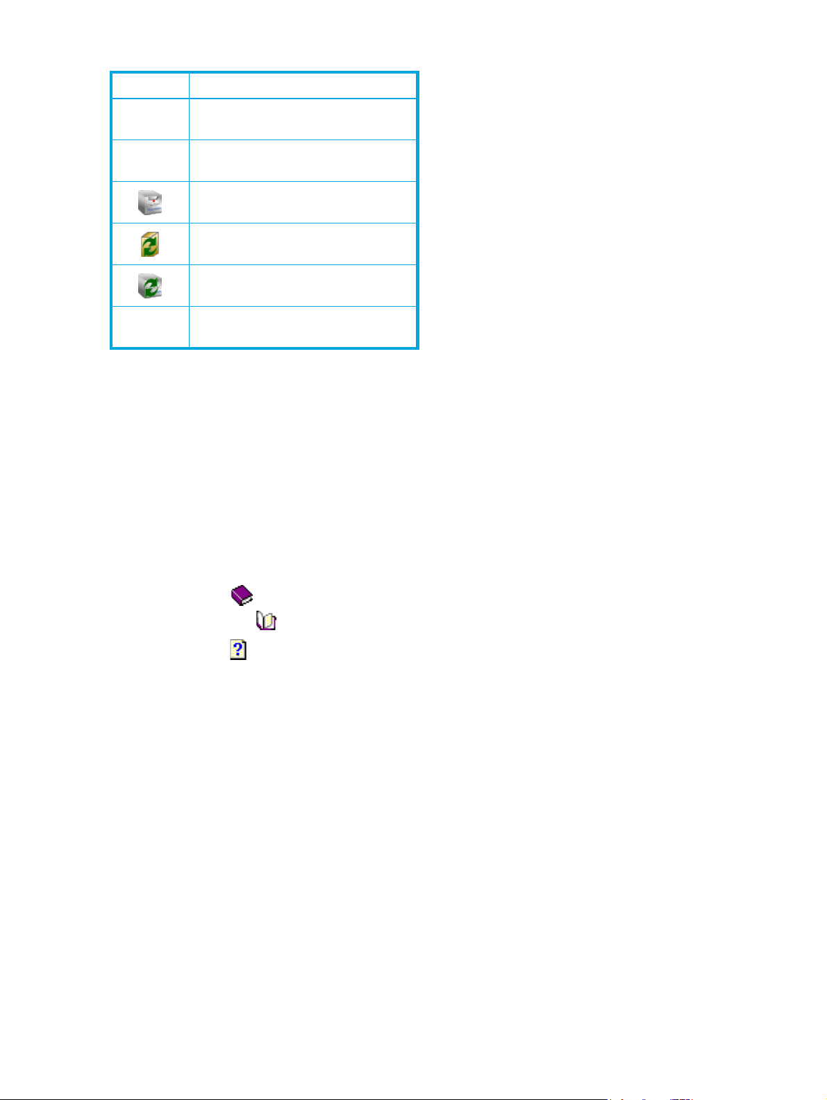
Table 7 Toolbar buttons (continued)
Button Purpose
Delete a logical disk
Create and manage partitions
Manage the storage subsystem
Refresh the server list
Refresh the subsystem list
Open the About box
Using the help system
The Simple SAN Connection Manager’s help system provides quick access to information about
performing tasks and completing dialog boxes.
To access the help system from Simple SAN Connection Manager, choose one of the following options:
• On the Help menu, click Contents.
• To view a help topic related to the current dialog box or window, click the Help button or press the F1
key.
The help system’s left pane contains the following tabs:
• The Contents tab shows a structured presentation of help topics. In Contents view, the following icons
are associated with topics:
• A book icon indicates a major grouping containing subordinate topics. Click a book icon to
“open” the book and see individual topics that belong to that group.
• A topic icon indicates a help topic. Click a topic icon to view the topic’s contents in the right
pane.
• The Index tab shows an alphabetical listing of keywords associated with the help topics. You can either
scroll through the list to find keywords, or enter a keyword to search for the topic. Then you can choose
from the one or more topics associated with that keyword.
• The Search tab enables you to quickly find a topic containing one or more words. Just type the text you
want to search for, and then click List Topics. To customize your search, select any of the check boxes in
the lower-left corner.
• The Favorites tab provides a place for you to save a list of topics you find useful or return to frequently.
To add the topic you are currently viewing to your list of favorites, click the Favorites tab, and then click
Add.
To print a help topic:
1. Find and open the help topic you want, or highlight a book or topic on the Contents tab.
2. On the help Options menu, click Print.
3. Select the printing options for your printer, and then click Print.
To return to previous topics:
• To return to a topic you have visited previously, click Back. To mark frequently used topics, click
Favorites, and then click Add.
34 Getting started
Page 35

Starting Simple SAN Connection Manager
Follow these steps to start Simple SAN Connection Manager. You will need to perform some of these steps
only the first time you start the application.
To start Simple SAN Connection Manager:
1. To launch the application, choose one of the following options:
•Click Start, point to All Programs > Hewlett-Packard > HP StorageWorks Simple SAN Connection
Manager, and then click HP StorageWorks Simple SAN Connection Manager.
• Double-click the desktop shortcut:
If this is the first time you have launched this software for a new, uninitialized EVA subsystem or an
unconfigured MSA subsystem, the installer prompts you to configure it.
2. Choose one of the following options:
•Click Yes to configure the subsystem using the Storage Deployment wizard (see “Configuring a
storage subsystem” on page 121).
• Depending on the type of subsystem you have, click No to either:
• Initialize an EVA subsystem. Continue with step 3.
• Ignore initialization of an MSA subsystem; it is not required. Skip to step 4
If this is not the first time you have launched this software, or if your storage subsystem is HP EVA and
you chose No in step 2, the Initialize an EVA Storage Subsystem dialog box (Figure 11) opens.
If this is not the first time you have launched this software, or if your storage subsystem is HP MSA and
you chose No in step 2, go to step 4.
NOTE: If the software detects that another server is managing your EVA storage array, a message
box asks if you want to disable that server and take over management of the EVA from this server.
Click Yes to proceed.
Figure 11 Initialize an Enterprise Virtual Array (EVA) Storage Subsystem dialog box
3. Enter a name to identify this new storage subsystem array, and then click OK to initialize the subsystem
using the default configuration. (This step is not required for MSA storage.)
HP StorageWorks Simple SAN Connection Manager user guide 35
Page 36

4. Wait while the application discovers (detects) switches, servers, storage subsystems, and logical disks.
This may take a few minutes.
If the application detects a new, unconfigured switch in your SAN, the New Switch Setup dialog box
(Figure 12) opens.
Figure 12 New Switch Setup dialog box
The New Switch Setup dialog box prompts you to set up the new switch by completing these three
steps:
1. Set switch IP address
2. Set switch administrator password
3. Set switch zoning: HBA zoning
5. Choose one of the following options:
• To continue with the first step (setting the switch IP address), click OK. The Set Switch IP Address
dialog box (Figure 13) opens. Go to step 6.
• To skip the switch setup for now, click Cancel. (To set up the switch later, see the procedures in
“Managing switches” on page 49. If you do not complete switch set up before you exit Simple SAN
Connection Manager, the New Switch Setup dialog box will open again the next time you start the
application.)
The Set Switch IP Address dialog box (Figure 13) shows the switch name and default IP address.
36 Getting started
Page 37

Figure 13 Set Switch IP Address dialog box: new switch setup
6. Select either the Enable IPv4 or Enable IPv6 check box, and then complete the appropriate IPv4 or IPv6
information (for details, see “Setting the switch IP address” on page 55). Click OK.
The New Switch Setup dialog box now shows a check mark next to the first step, “Set switch IP
address,” (Figure 14) indicating that you have completed that task.
Figure 14 First step of New Switch Setup completed
7. A message box asks if you want to change the factory default switch administrator password. Choose
one of the following options:
• To continue with the next step of switch setup, click Yes. The Set Switch Admin Password dialog box
(Figure 15) opens. Go to step 8.
• To change the default password later, click No. (See “Setting the switch admin password,” page 55,
for a procedure for changing the switch admin password—either the default or the current
password—to a new password.)
HP StorageWorks Simple SAN Connection Manager user guide 37
Page 38

Figure 15 Set Switch Admin Password dialog box: new switch setup
8. In the Set Switch Admin Password dialog box, complete the following steps:
a. Enter the Old Password (the factory default password for the switch is password).
b. Enter a New Password (at least 8 alphanumeric characters).
c. Re-enter the new password in the Verify Password box.
d. To set the switch admin password, click OK. To cancel password setup, click Cancel.
9. A message box confirms successful password change completion. Click OK to close the message box.
The New Switch Setup dialog box now shows a check mark next to the second step, “Set switch
administrator password,” (Figure 16) indicating that you have completed that task.
Figure 16 Second step of New Switch Setup completed
10. A message box asks if you want to set the switch zoning. Choose one of the following options:
• To continue with the next step of switch setup, click Yes. The Set the Switch Default Zoning dialog
box (Figure 17) opens. Go to step 9.
• To set the switch zoning later, click No. (See “Setting the switch default zoning,” page 53, for a
procedure for changing the switch zoning.)
38 Getting started
Page 39

Figure 17 Set the Switch Default Zoning dialog box: new switch setup
The Set the Switch Default Zoning dialog box contains the following information:
• Default zone set name—Shows the default name for the current switch zoning configuration.
• Zone List—Shows the existing HBA zones with its HBA adapter and devices. If a zone list is closed
(the Switch Port #, Type, and Vendor information is hidden), click the plus mark (+) to open it.
• Switch Name (Port #)—Indicates the switch name and port number for each HBA and device.
• Type—Indicates the kind of device; for example, HBA or RAID storage.
• Vendor—Indicates the seller for the hardware indicated.
11 . Complete the Set the Switch Default Zoning dialog box as follows:
a. In the Default zone set name box, enter a new name for your configuration.
b. To exclude a storage port from the zone, clear the check box next to the port name. To include a
storage port in the zone, select the check box next to it.
c. To save the new switch default zoning setup, click OK. To stop the switch zoning changes, click
Cancel.
The New Switch Setup dialog box now shows a check mark next to the third step, “Set switch
administrator password,” (Figure 18) indicating that you have completed that task.
Figure 18 Third step of New Switch Setup completed
12 . Click Close to close the New Switch Setup dialog box for this switch.
HP StorageWorks Simple SAN Connection Manager user guide 39
Page 40

13 . If Simple SAN Connection Manager detects another unconfigured switch, the New Switch Setup
wizard opens again for that switch and guides you through its setup.
After you have either completed all the steps required in the New Switch Setup procedures (step 4
through step 9), or opted not to set up the switch at this time, the Welcome… Configure Your SAN
dialog box (Figure 19) appears.
Figure 19 Welcome… Configure Your SAN dialog box
14. Select from the following SAN configuration options:
• To prevent the Welcome dialog box from opening every time you start Simple SAN Connection
Manager, clear the Always show this screen at the application startup check box. (Be aware that if
you clear this check box, you cannot later reinstate the Welcome dialog box.)
• To exit this dialog box without performing any configuration, and view the Simple SAN Connection
Manager main window, click Close. (All configuration options offered on this dialog box are also
available from the main window.)
• To launch the Create New Logical Disk wizard and add a new logical disk to your SAN, click
Create Logical Disk Wizard. For details, see either “Creating a logical disk—EVA storage” on
page 84 or “Creating a logical disk—MSA storage” on page 88.
• To open the Perform Other Operations dialog box (Figure 20) and select from additional
configuration options, click Perform Other Operations.
40 Getting started
Page 41

Figure 20 Perform Other Operations dialog box
15 . If you clicked Perform Other Operations on the Welcome... Configure Your SAN dialog box, select
from these common SAN configuration operations:
Logical Disk and Partition Operations:
•Click Assign Logical Disk to Server to open the Logical Disk Server Presentation dialog box (see
“Assigning and unassigning a logical disk to a server” on page 95).
•Click Create & Manage Partitions to open the Create & Manage Partitions dialog box (see
“Creating and managing partitions” on page 105).
•Click Expand Logical Disk Size to open the Expand Logical Disk dialog box (see “Expanding a
logical disk” on page 97).
•Click Delete Logical Disk to open the Delete Logical Disk dialog box (see “Deleting a logical
disk” on page 98).
Drive Operations:
•Click Manage Hot Spare Drive to set or remove a drive as a hot spare from the Manage Storage
Subsystem dialog box (see “Managing storage subsystems” on page 116).
•Click Blink Drive LED to flash a drive’s LED from the Manage Storage Subsystem dialog box (see
“Managing storage subsystems” on page 116).
Switch Operations:
•Click Set Switch IP Address to open the Set Switch IP Address dialog box (see “Setting the switch
IP address” on page 55).
•Click Update Switch Firmware to open the Switch Firmware Update wizard (see “Updating
switch firmware” on page 57).
HBA Operations:
•Click Update HBA BIOS to open the Update HBA BIOS wizard (see “Updating an HBA BIOS
image” on page 76).
HP StorageWorks Simple SAN Connection Manager user guide 41
Page 42

•Click Update HBA Driver to open the HBA Driver Update wizard (see “Updating an HBA driver”
on page 78).
16. To exit this dialog box without performing any configuration, and view the Simple SAN Connection
Manager main window, click Close. (All configuration options offered on this dialog box are also
available from the main window.)
Now that you have completed the initial switch setup and other common configuration operations, you can
use Simple SAN Connection Manager to configure your SAN, as described in the remainder of this guide.
42 Getting started
Page 43

4 Viewing maps, events, and configurations
This chapter provides procedures that describe the following options:
• “Viewing a Physical Connection map,” page 43
• “Viewing a LUN Assignment map,” page 44
• “Viewing the event log,” page 45
• “Saving and comparing SAN configurations,” page 46
Viewing a Physical Connection map
Simple SAN Connection Manager provides a graphical representation of physical connections among the
storage subsystems, switches, and HBAs within the SAN. This graphical representation is the Physical
Connection map shown in the content pane (see Figure 21).
Description of a Physical Connection map
The Physical Connection map (Figure 21) uses blue lines to designate the physical connections between
devices in the SAN.
Figure 21 Physical Connection map
The map shows the following components:
• Switches:
• A black line between switches indicates an inter-switch link (ISL).
• A grayed-out switch on the map indicates a remote fabric (Brocade fabric that may contain multiple
switches) connected by means of an active TR_Port.
• An orange line (or lines) from the HP StorageWorks 8/20q Fibre Channel Switch to a grayed-out
switch indicates a connection between an active TR_Port and the remote fabric, but appears only if
the switch has been configured with Inter-Fabric Zones (IFZs). For more information, see “Ab out
transparent routing” on page 49.
• Servers
• HBAs
• Storage subsystems
• Storage subsystem controllers
• Storage subsystem controller’s ports
HP StorageWorks Simple SAN Connection Manager user guide 43
Page 44

NOTE: The information presented is read-only. You can right-click any of the icons representing switches,
HBAs, servers, and subsystems to open a shortcut menu for that component.
How to view a Physical Connection map
To view a physical connection map:
1. In the navigation pane, click on the root of the navigation pane:
• If the navigation pane displays the Storage Subsystem - Logical Disk View, the root is called
Subsystem - Logical Disk.
• If the navigation pane displays the Server - Storage View, the root is called Server - Logical Disk.
2. The content pane shows a topology map. If the map displayed is LUN Assignment map, click the
Physical Connection Map tab to bring that map forward.
Viewing a LUN Assignment map
Simple SAN Connection Manager provides a graphical representation for the access to logical disks from
the HBAs and servers within the SAN. This graphical representation is the LUN Assignment map shown in
the content pane (see Figure 22).
Description of a LUN Assignment map
The LUN Assignment map (Figure 22) shows the actual access link between the HBAs and servers to the
subsystems’ logical disks. The blue lines indicate that the HBAs or servers are allowed to have access to the
logical disk.
Figure 22 LUN Assignment map
The map shows the following components:
• Storage subsystems
• LUNs
• Servers (Click the server name or icon to show or hide the HBAs on the topology map.)
• HBAs
NOTE: The information presented is read-only. You can right-click any of the icons representing the
subsystem, LUNs, HBAs, and servers to open the shortcut menu for that component.
How to view a LUN Assignment map
To view a LUN Assignment map:
1. In the navigation pane, click on the root of the navigation pane:
44 Viewing maps, events, and configurations
Page 45

• If the navigation pane displays the Storage Subsystem - Logical Disk View, the root is called
Subsystem - Logical Disk.
• If the navigation pane displays the Server - Storage View, the root is called Server - Logical Disk.
2. The content pane opens a topology map. If the map shown is Physical Connection map, click the LUN
Assignment Map tab to bring that map forward.
Viewing the event log
The event log lists all Simple SAN Connection Manager-initiated actions and the results for the host, HBAs,
switches, and storage subsystems. The event log begins recording when Simple SAN Connection Manager
is running. Event log entries are formatted by type, time stamp, category, source, event ID, and description.
The log holds a maximum of 1,999 entries. When the maximum is reached, the event list wraps, and the
oldest events are discarded and replaced with the new events.
The Type column icon and text indicate an entry’s severity:
Info indicates information only.
Warning indicates a minor warning condition.
Error indicates an error condition.
To view the event log:
• On the File menu, click Event Log.
The Application Event Log dialog box (Figure 23) opens.
Figure 23 Application Event Log dialog box
To clear the entire event log:
• On the bottom of the Application Event Log dialog box, click the Clear Logs button. The event log is
emptied and ready for more entries.
To clear specific entries:
1. Right-click a specific event log entry (to select multiple entries, click the entries while holding down the
CTRL key).
2. On the shortcut menu, click Delete Entry to remove the selected entries from the event log.
HP StorageWorks Simple SAN Connection Manager user guide 45
Page 46

To export the event log:
1. On the bottom of the Application Event Log dialog box, click the Export button to open the Export Event
Log dialog box.
2. Navigate to the location where you want to save the event log, and then enter a name for the file with
either an .XML, .CSV, or .TXT extension.
3. Click Save.
Saving and comparing SAN configurations
You can save the current SAN connection configuration (see “Saving the current configuration,” page 46),
and compare that configuration with a previous configuration (see “Comparing configurations,” page 46).
Saving the current configuration
Simple SAN Connection Manager provides the ability to save a graphical topology of your current SAN
that can be easily viewed to note any changes made to your system. You should save your SAN
connections before making changes so that you can then see the differences (see “Comparing
configurations,” page 46).
To save a configuration:
• On the File menu, click Save current SAN connection.
NOTE: Simple SAN Connection Manager automatically saves the current configuration when you close
the application.
Comparing configurations
Simple SAN Connection Manager provides the ability to compare any changes to your current SAN with
the previous configuration.
To compare a configuration:
1. On the File menu, click Compare current and previous SAN connection.
The Compare Current and Previous Configuration dialog box (Figure 24) opens.
46 Viewing maps, events, and configurations
Page 47

Figure 24 Compare Current and Previous Configuration dialog box
This dialog box shows a graphical representation listing:
• Removed servers
•New servers
•New HBAs
•Removed switch(es)
•New switch(es)
• Removed storage subsystem(s)
•New storage subsystem(s)
2. When you finish reviewing the dialog box, click Close.
HP StorageWorks Simple SAN Connection Manager user guide 47
Page 48

48 Viewing maps, events, and configurations
Page 49

5 Managing switches
This chapter provides the following procedures for viewing and managing your HP StorageWorks 8/20q
Fibre Channel Switches using Simple SAN Connection Manager:
• “About transparent routing,” page 49
• “Viewing switch properties,” page 49
• “Viewing network properties,” page 50
• “Viewing switch zoning information,” page 51
• “Setting the switch default zoning,” page 53
• “Setting the switch admin password,” page 55
• “Setting the switch IP address,” page 55
• “Updating switch firmware,” page 57
• “Setting switch SNMP properties,” page 59
• “Setting the switch symbolic name and domain ID,” page 62
• “Setting DNS properties,” page 62
• “Setting switch IP security,” page 64
About transparent routing
The transparent routing feature provides inter-fabric routing to allow controlled and limited access between
devices on an HP StorageWorks 8/20q Fibre Channel Switch (local) fabric and devices on a remote fabric
consisting of switches made by other vendors. This type of inter-fabric connection uses the Fibre Channel
industry N_Port ID Virtualization (NPIV), and makes local and remote devices accessible to each other
while maintaining the local and remote fabrics as separate fabrics.
Transparent routing configuration consists of connecting the local fabric over one or more TR_Ports to the
remote fabric, and then creating Inter-Fabric Zones (IFZs) by which you map the local devices to the remote
devices. To complete the configuration and make it active, you must activate the same IFZs on both the
local fabric and the remote fabric.
Simple SAN Connection Manager displays, on the Physical Connection map (see page 43), the remote
fabric as a grayed-out switch, which represents one or more HP StorageWorks B-series switches and their
connected devices. However, Simple SAN Connection Manager cannot be used to manage the remote
fabric or to configure transparent routing. To configure transparent routing, use the HP StorageWorks
8/20q Fibre Channel Switch QuickTools web applet as described in the HP StorageWorks 8/20q Fibre
Channel Switch QuickTools switch management user guide.
Viewing switch properties
Simple SAN Connection Manager provides a quick and easy way to view properties related to switches
within your SAN.
Description of the switch properties
The Switch Properties (Figure 25) include the following read-only information:
•Symbolic Name
•Model
•World-wide name
•Serial Number
•MAC Address
•Domain ID
•Firmware Version
• Operational State
HP StorageWorks Simple SAN Connection Manager user guide 49
Page 50

Figure 25 Switch Properties
How to view switch properties
To view switch properties:
1. To access the switch properties, choose one of the following options:
• On the HBA & Switch Management menu, click Get Switch Properties. If there is only one switch in
your SAN, it’s properties appear. If there is more than one switch, the Switch Selection dialog box
opens; continue with step 2.
• On the content pane’s Physical Connection map, right-click the switch icon, and on the shortcut
menu, click Get Switch Properties.
2. If the Switch Selection dialog box opens, select the switch you want to view.
3. When you finish viewing the switch properties, click OK to close the dialog box.
Viewing network properties
Simple SAN Connection Manager provides a quick and easy way to view properties related to your
storage area network.
Description of the network properties
The Network Properties (Figure 26) include the following read-only information:
• IPv4 network settings: Enabled, Address, Subnet Mask, and Gateway
• IPv6 network settings: Enabled, Address, Gateway, and Assigned Addresses
•SNMP Enabled
• Broadcast Support Enabled
•DNS Enabled
• Configured Local Hostname (if any)
• Assigned Local Hostname (if any)
50 Managing switches
Page 51

Figure 26 Network Properties
How to view network properties
To view network properties:
1. To access the switch properties, choose one of the following options:
• On the HBA & Switch Management menu, click Get Network Properties. If there is only one switch,
the switch is automatically selected; continue with step 3. If there is more than one switch, the Switch
Selection dialog box opens; continue with step 2.
• On the content pane’s Physical Connection map, right-click the switch icon, and on the shortcut
menu, click Get Network Properties.
2. If the Switch Selection dialog box opens, select the switch you want to view.
3. When you finish viewing the network properties, click OK to close the dialog box.
Viewing switch zoning information
The Switch Zoning Information dialog box provides facts about the current switch zoning setup. This
information is read-only; you cannot make changes on this dialog box. To change switch zoning, see
“Setting the switch default zoning” on page 53.
To view switch zoning information:
1. On the HBA & Switch Management menu, click Get Switch Zoning Information.
The Switch Zoning Information dialog box (Figure 27) opens.
HP StorageWorks Simple SAN Connection Manager user guide 51
Page 52

Figure 27 Switch Zoning Information dialog box
This dialog box shows the following current information about your switch:
• Zone List—Lists all zones and the members of each. The currently active zones are shown in a darker
color.
• Switch Name (Port #)—Shows the switch name and, in parentheses, the number of the switch port
that is attached to the HBA or RAID storage device.
• Port Type—Shows the type of port; for example, HBA or RAID storage.
• Vendor—Attached device manufacturer name; for example, Hewlett Packard.
2. When you finish viewing the switch zoning information, click OK to close the dialog box.
NOTE: If you have transparent routing configured with Inter-Fabric Zones (IFZs) activated (see “About
transparent routing” on page 49), the switch zoning information may appear in Simple SAN Connection
Manager as shown in Figure 28. IFZs appear as “Zone: IFZ_xxxxxxxxxxxxxxxx_xxxxxxxxxxxxxxxx,”
followed by the Port WWN of each TR_Port, host port, and storage port. If known, the Switch Name, Port
Type, and Vendor information are shown; otherwise, this information is displayed as “Unknown.”
52 Managing switches
Page 53

Figure 28 Switch Zoning Information dialog box (TR_Ports mapping)
Setting the switch default zoning
CAUTION: Altering the active zoning configuration can disrupt SAN traffic.
A zone is a named group of ports or devices. Members of the same zone can communicate with each
other and transmit outside the zone, but cannot receive inbound traffic from outside the zone. Zoning
divides the fabric for purposes of controlling discovery and inbound traffic.
Based on the HBA and storage ports connected to the switch, Simple SAN Connection Manager can set
the switch zoning to an HBA-based zoning scheme where each HBA is in its own zone along with all the
storage ports.
Use the Set the Switch Default Zoning dialog box to set a default zone and include or exclude a device
from a zone.
NOTE: When the Set the Switch Default Zoning dialog box first opens, all the devices are included in
zones.
To set the switch default zoning:
1. From the HBA & Switch Management menu, click Set Switch HBA-based Default Zoning.
HP StorageWorks Simple SAN Connection Manager user guide 53
Page 54

If the switch already has an active zoning setup, a message box asks if you want to remove and
replace existing zoning with the default HBA-based zoning and advises you to carefully review the
current active zoning. Be aware that modifying zoning can disrupt SAN traffic.
2. To close the message box and continue, click Yes. To cancel switch default zoning setup, click No.
The Set the Switch Default Zoning dialog box (Figure 29) opens.
Figure 29 Set the Switch Default Zoning dialog box
This dialog box contains the following information:
• Zone List—Shows the existing HBA zones with its HBA adapter and devices. If a zone list is closed
(the Switch Name, Port #, Type, and Vendor information is hidden), click the plus mark (+) to open
it.
• Switch Name (Port #)—Shows the switch name and, in parentheses, the number of the switch port
that is attached to the HBA or RAID storage device.
• Type—Indicates the kind of device, for instance HBA or RAID storage.
• Vendor—Attached device manufacturer name; for example HP.
3. In the Default zone set name box, enter a name for the new default zone set.
4. To exclude a storage port from the new zone set, clear the check box next to the port name. To include
a storage port in the new zone set, select the check box next to it.
5. To save the new switch default zoning setup, click OK. To abandon the switch zoning changes, click
Cancel.
NOTE: To use other zoning schemes, use the QuickTools switch management web applet to set the
zoning. To start the switch QuickTools web applet, click the Physical Connection Map tab, right-click the
switch icon, and then on the shortcut menu, click Launch the switch QuickTool application.
54 Managing switches
Page 55

Setting the switch admin password
Simple SAN Connection Manager provides a quick and easy way to set switch administrator passwords
within your SAN. These passwords are required for all update operations to be performed on the switch,
including:
• Updating firmware
• Setting switch symbolic name
• Setting domain ID
Setting switch admin passwords prevents unauthorized users from performing these operations.
To set a switch admin password:
1. To access the Set Switch Admin Password dialog box, choose one of the following options:
• On the HBA & Switch Management menu, click Set Switch Admin Password.
• In the content pane’s Physical Connection map, right-click the switch icon to select a specific switch,
and then on the shortcut menu, click Set Switch Admin Password.
The Set Switch Admin Password dialog box (Figure 30) opens.
Figure 30 Set Switch Admin Password dialog box
2. If no specific switch is selected, select the switch you want from the drop-down list at the top of the
dialog box. If a specific switch has been selected, the drop-down list is disabled.
3. In the Old Password box, enter the current admin login password. (The default Old Password is
password.)
4. In the New Password box, enter a new admin login password.
5. In the Verify Password box, re-enter the new password.
6. To change the password, click OK. To abandon the password change, click Cancel.
Setting the switch IP address
Simple SAN Connection Manager provides a quick and easy way to set switch IP addresses within your
SAN. This IP address allows the switch to be managed through the Ethernet link. Updating the switch’s
firmware, for example, requires the switch to have a valid IP address that the Simple SAN Connection
Manager server can use to communicate to the switch over the IP network. Simple SAN Connection
Manager supports both IPv4 and IPv6 addresses.
HP StorageWorks Simple SAN Connection Manager user guide 55
Page 56

NOTE: If the protocol stack on the switch is currently disabled, setting the switch IP address will enable the
stack.
To set a switch IP address:
1. To access the Set Switch IP Address dialog box, choose one of the following options:
• On the HBA & Switch Management menu, click Set Switch IP Address.
• In the content pane’s Physical Connection map, right-click a switch icon to select that specific switch,
and then on the shortcut menu, click Set Switch IP Address.
2. If no specific switch is selected and if there is more than one switch in the SAN, the Switch Selection
dialog box opens. Select the switch you want to change, and then click OK.
The Set Switch IP Address dialog box (Figure 31) opens.
Figure 31 Set Switch IP Address dialog box
The dialog box shows the switch name and its current IP address on the top portion, and enables you to
set either an IPv4 or IPv6 address for the switch on the bottom portion.
3. To set an IPv4 address for the switch, select the Enable IPv4 check box, and then enter a valid IPv4
address, subnet mask, and gateway in the appropriate boxes.
4. To set an IPv6 address for the switch, select the Enable IPv6 check box, and then complete the following
for IPv6:
a. From the IPv6 Discovery list, select one of the following:
• Static—Select this option to enable the IPv6 address and gateway boxes and define those
values.
• DHCPv6—Select this option to use Dynamic Host Configuration Protocol for IPv6. DHCPv6 can
be used to statefully assign addresses if the network administrator needs more control over
addressing. It can also be used to distribute information that is not otherwise discoverable; for
example, the DNS server. (If you select DHCPv6, the IPv6 address and gateway boxes become
unavailable.)
56 Managing switches
Page 57

• NDP—Select this option to use Neighbor Discovery Protocol for IPv6, as part of the Stateless
Address Autoconfiguration protocol. (If you select NDP, the IPv6 address and gateway boxes
become unavailable.)
b. If you selected Static for IPv6 Discovery, enter a valid address in the IPv6 Address box.
NOTE: Ensure that you append a forward slash (/) and address mask length at the end of the IPv6
address. Valid mask lengths range from 0 through 128. In the following example, the combination
of alphanumeric characters and colons (:) before the slash specify the IPv6 address and 96
specifies the mask length:
fd70:c154:c2df:116:20b:cdff:feca:2942/96
c. If you selected Static for IPv6 Discovery, enter a valid gateway in the IPv6 Gateway box.
5. To save your changes to the switch IP address and close this dialog box, click OK. To close this dialog
box without making changes, click Cancel.
Updating switch firmware
Simple SAN Connection Manager provides an easy way to update firmware for switches in your SAN.
To update switch firmware:
1. To access the Switch Firmware Update wizard, choose one of the following options:
• On the HBA & Switch Management menu, click Update Switch Firmware.
• In the content pane’s Physical Connection map, right-click a specific switch icon, and then on the
shortcut menu, click Update Switch Firmware.
The Switch Firmware Update wizard opens.
2. If a specific switch is selected, click Next and skip to step 4. If no specific switch is selected, the wizard
(Figure 32) prompts you to select one or more switches; continue with step 3.
Figure 32 Switch Firmware Update Wizard: selecting a switch
HP StorageWorks Simple SAN Connection Manager user guide 57
Page 58

3. In the Switch Firmware Update wizard’s Available Switch(es) list, select one or more switches for which
you want to update the firmware as follows:
a. Choose one of the following options:
• Select a switch on the Available Switch(es) list, and then click Add.
• To select all of the available switches, click Add All.
b. Click Next. (Next is disabled until you select at least one switch and add it to the Selected
Switch(es) list.)
NOTE: If you select and add a switch by mistake, select that switch on the Selected Switch(es) list,
and then click Remove. To clear the Selected Switch(es) list and start the selection again, click
Remove All.
The wizard window lists switches selected for firmware update. The list provides the following
information:
• Switch name.
• Current switch firmware version.
• Firmware image file name (this field is blank until you click and complete Select Switch Firmware
File—see step 4).
• Switch administrator password for authentication (this field is blank until you click and complete
Switch Admin Password—see step 6).
• Option to apply the new firmware image right after the update or wait until the next time the switch
is turned off, and then back on. (This field is blank until you click and complete Switch Admin
Password—see step 6).
NOTE: If the switch name and current firmware version shown are not correct, try to get the switch
properties first. For details, see “Viewing switch properties” on page 49.
4. Click Select Switch Firmware File.
5. Navigate to the folder containing the required file for the switch, select the firmware file, and then click
Open.
The Updated FW Image File column shows the file name.
6. Click Switch Admin Password.
The Switch User Name and Password for Firmware Update dialog box (Figure 33) opens.
Figure 33 Switch User Name and Password for Firmware Update dialog box
58 Managing switches
Page 59

7. In this dialog box, complete these steps:
a. Enter the user name and password.
b. (Optional) If you want the firmware update to take affect immediately, rather than after the switch
power is recycled, select the Apply the new firmware image immediately after successful update
check box.
c. Click OK.
8. Repeat steps 4 through 7 for each switch you want to update, and then continue with step 9.
9. On the completed Switch Firmware Update wizard window (Figure 34), click Next.
Figure 34 Switch Firmware Update wizard
10. To complete the wizard, choose one of the following options:
• To confirm and proceed with the firmware update, click Finish.
• To change your selections for the firmware update, click Back.
• To stop the firmware update, click Cancel.
If you clicked Finish, a message may inform you that the switch firmware is ready to be updated. The
process takes several minutes per switch and cannot be canceled. Also, switch traffic may be
temporarily disrupted.
11 . Click Yes when prompted to update the switch firmware.
Setting switch SNMP properties
Use the SNMP Properties dialog box to define how authentication traps are managed and set for the
switch. Simple Network Management Protocol (SNMP) is the protocol that governs network management
and monitoring of network devices. SNMP security consists of a read community string and a write
community string, which are basically the passwords that control read and write access to the switch.
HP StorageWorks Simple SAN Connection Manager user guide 59
Page 60

CAUTION: The read community string (“public”) and write community string (“private”) are set at the
factory to these well-known defaults and should be changed if SNMP is enabled. If SNMP is enabled
(default) and the read and write community strings have not been changed from their defaults, you risk
unwanted access to the switch. It is very important that you consider how you want to manage the fabric
and what switches you do not want managed through another switch.
To set the switch SNMP properties:
1. To access the SNMP Properties, choose one of the following options:
• On the HBA & Switch Management menu, click Set Switch SNMP Properties. (If you have more than
one switch in your SAN, the Switch Selection dialog box prompts you to select a switch, and then
click OK.)
• In the content pane’s Physical Connection map, right-click a specific switch icon, and then on the
shortcut menu, click Set Switch SNMP Properties.
The SNMP Properties dialog box (Figure 35) opens.
Figure 35 SNMP Properties
NOTE: Because Read Community, Write Community, and Trap Community settings are like
passwords, they are write-only fields and the current settings are not shown.
Illegal characters are the pound sign (#), semi-colon (;), and comma (,).
2. In the top section, SNMP Configuration, define how authentication traps are managed by completing
the following settings.
SNMP Enabled Select this check box to allow SNMP communication with other switches in the
Contact Enter the name (maximum 64 characters) of the contact person who responds to
60 Managing switches
fabric. Clear this check box to prevent an SNMP application at a workstation to
talk to this switch.
trap events. The default is sysContact undefined.
Page 61

Read Community Enter the Read Community password (maximum 32 characters) that authorizes
an SNMP agent to read information from the switch. This is a write-only field.
The value on the switch and the SNMP management server must be the same.
The default is public.
Write Community Enter the Write Community password (maximum 32 characters) that authorizes
an SNMP agent to write information to the switch. This is a write-only field. This
value on the switch and the SNMP management server must be the same. The
default is private.
SNMP Proxy Select this check box to allow the use of SNMP to monitor and configure any
switch in the fabric. Clear this check box to prevent this function.
Location Enter a name (maximum 64 characters) for the switch location.
Authentication Trap Allows reporting of SNMP authentication failures. In the event of an
authentication failure caused by incorrect community string values, a notification
trap is sent to the configured trap addresses. Click True to enable this feature, or
click False to disable this feature. The default value is False.
The lower portion of the SNMP Properties dialog box contains tabs for each SNMP Trap Configuration,
which define how each of the five traps are set.
3. For Trap 1, complete the following configuration settings:
Trap Enabled Select this check box to enable this trap. Clear this check box to disable this trap
(traps are not sent to trap monitoring stations and you cannot configure a
disabled trap).
Trap Version Select the SNMP version (V1 or V2) with which to format the traps.
Trap Address
(see note below)
Enter the IPv4 or IPv6 address, or DNS host name, to which SNMP traps are
sent. A maximum of five trap addresses are allowed, if the firmware on the switch
supports the trap community string per trap enhancement. The default address
for Trap 1 is 10.0.0.254. The default address for Traps 2 through 5 is 0.0.0.0.
Trap Community Enter the Trap Community password that authorizes an SNMP agent to receive
traps. This is a write-only field. The value on the switch and the SNMP
management server must be the same. The default is public. You may enter up to
32 characters.
Note that for switches running 7.4 or newer firmware, the Trap Community string
is now per-trap. With firmware older than 7.4, there is just one Trap Community
string for all SNMP configuration.
Trap Severity Select a severity level to assign to the trap. Trap severity levels include Unknown,
Emergency, Alert, Critical, Error, Warning, Notify, Info, Debug, and Mark.
Trap Port
Enter the number (1–65535) of the port on which a trap is set.
(see note below)
NOTE: The Trap Address (other than 0.0.0.0) and Trap Port combination must be unique. For
example, if Trap 1 and Trap 2 have the same address, they must have different port values.
Similarly, if Trap 1 and Trap 2 have the same port value, they must have different addresses.
However, you can have multiple trap destinations with the same address, if you ensure that the port
values are different. You can accomplish this via clish (command line interface shell) using a
two-step process. First, set the address to something unique, modify the port, and save/activate.
Second, go back in and set the address to one that is already set as a different trap destination.
4. To set additional traps, click the Trap 2 through Trap 5 tabs to bring each of those tabbed pages to the
front and complete the settings on those pages (for details, refer to step 3).
5. To save the switch SNMP configuration settings and close this dialog box, click OK. To close the dialog
box without making any changes, click Cancel.
HP StorageWorks Simple SAN Connection Manager user guide 61
Page 62

Setting the switch symbolic name and domain ID
Use the Set Switch Symbolic Name and/or Domain ID dialog box to change the symbolic switch name or
the domain ID.
To change the switch symbolic name and domain ID:
1. To access the Set Switch Symbolic Name and/or Domain ID dialog box, choose one of the following
options:
• On the HBA & Switch Management menu, click Set Switch Symbolic Name and/or Domain ID. (If
you have more than one switch in your SAN, the Switch Selection dialog box prompts you to select
a switch, and then click OK.)
• In the content pane’s Physical Connection map, right-click a switch icon to select that specific switch.
Then on the shortcut menu, click Set Switch Symbolic Name and/or Domain ID.
The Set Switch Symbolic Name and/or Domain ID dialog box (Figure 36) opens and shows the current
symbolic name and domain ID.
Figure 36 Set Switch Name and/or Domain ID dialog box
2. If you want to change the symbolic name, enter a new name (maximum 32 characters) in the Symbolic
Name box.
3. If you want to change the domain ID, enter a new name in the Domain ID box.
4. To make the changes and close the dialog box, click OK. To close the dialog box without making any
changes, click Cancel.
Setting DNS properties
Simple SAN Connection Manager enables you to set the Domain Name System (DNS; aka Domain Name
Server) on the switch. DNS is a system that stores all the information associated with domain names in a
database. DNS is used to attach easy-to-remember domain names to hard-to-remember IP addresses in the
form of URLs and e-mail addresses.
To set the switch DNS properties:
1. To access the DNS Properties dialog box, choose one of the following options:
• On the HBA & Switch Management menu, click Set DNS Properties. (If you have more than one
switch in your SAN, the Switch Selection dialog box prompts you to select a switch, and then click
OK.)
• In the content pane’s Physical Connection map, right-click a switch icon to select that specific switch.
Then on the shortcut menu, click Set DNS Properties.
The DNS Properties dialog box (Figure 37) opens.
62 Managing switches
Page 63

Set DNS Configuration
Figure 37 DNS Properties dialog box
2. Under DNS Options, complete the following:
a. To enable DNS on the switch, select the DNS Client check box. To disable DNS on the switch, clear
the check box.
b. If you enable DNS, in the Local Hostname box, enter a valid local host name.
3. Under DNS Server, complete the following:
a. From the Server Discovery list, select a method of DNS server discovery:
• Static—Select this option to manually configure the list of DNS domain suffixes to be searched,
enable the three DNS Server Address boxes and, optionally, define those values.
• DHCP—Select this option to use Dynamic Host Configuration Protocol for IPv4. DHCP allows the
switch to dynamically receive an IP address from a pool of addresses, instead of requiring it to
have a static IP address. Use DHCP to acquire the IP configuration from a DHCP server. If no
satisfactory lease is obtained, the DHCP client attempts to use the previously configured lease. If
the previous lease cannot be used, no IP address is assigned to this switch, in order to avoid an
IP address conflict. DHCP can also be used to distribute information that is not otherwise
discoverable; for example, the DNS server addresses. (If you select DHCP, the DNS Server
Address boxes become unavailable.)
• DHCPv6—Select this option to use Dynamic Host Configuration Protocol for IPv6. DHCPv6 can
be used to statefully assign addresses if the network administrator needs more control over
addressing. It can also be used to distribute information that is not otherwise discoverable; for
example, the DNS server. (If you select DHCPv6, the DNS Server Address boxes become
unavailable.)
HP StorageWorks Simple SAN Connection Manager user guide 63
Page 64

b. If you selected Static for Server Discovery, optionally enter up to three valid addresses in the DNS
Server Address boxes.
Use the DNS Search List to specify up to five DNS domain suffixes to be used by the DNS client when
attempting to resolve a host name into an IP address. For example, if the DNS Search List includes a
single domain name “servers.mycompany.com” and a client attempted to look up the host name
“myhost,” the DNS client will first request the IP address of the host name “myhost.” If that fails, it will
request the IP address of the host name, “myhost.servers.mycompany.com.”
4. Under DNS Search List, complete the following:
a. From the Search List Discovery list, select a method of assigning IP addresses:
• Static—Select this option to manually configure the list of DNS domain suffixes to be searched.
• DHCP—Select this option to use Dynamic Host Configuration Protocol for IPv4. DHCP allows the
switch to dynamically receive an IP address from a pool of addresses, instead of requiring it to
have a static IP address. DHCP can also be used to distribute information that is not otherwise
discoverable; for example, the DNS domain used for name resolution. (If you select DHCP, the
Search List Domain Name boxes become unavailable.)
• DHCPv6—Select this option to use Dynamic Host Configuration Protocol for IPv6. DHCPv6 can
be used to statefully assign addresses if the network administrator needs more control over
addressing. DHCPv6 can also be used to distribute information that is not otherwise
discoverable; for example, the DNS domain used for name resolution. (If you select DHCPv6, the
Search List Domain Name boxes become unavailable.)
b. If you selected Static for Search List Discovery, optionally enter up to five valid domain names in the
Search List Domain Name boxes.
5. To save your changes to the switch DNS properties and close this dialog box, click OK. To close this
dialog box without making changes, click Cancel.
Setting switch IP security
Network Internet Protocol security (IPsec) provides encryption-based security for IP version 4 (IPv4) and IP
version 6 (IPv6) communications through the use of security policies and associations.
IMPORTANT: IP security configurations can be complex. It is possible to unintentionally configure policies
and associations that isolate a switch from all communication. If this happens, you can disable IP security
by placing the switch in maintenance mode, and correct the problem through the serial port interface.
Simple SAN Connection Manager provides the IPsec Configuration dialog box to help you configure IPsec,
which is used to encrypt and authenticate IPv4 and IPv6 packets. Use the IPsec Configuration dialog box to
create, edit, delete, copy, and paste IPsec associations (see “Managing security associations” on page 64)
and IPsec policies (see “Managing security policies” on page 69).
Managing security associations
A security association defines the encryption algorithm and encryption key to apply when called by a
security policy. A security policy may call several associations at different times, but each association is
related to only one policy. The security association database (SAD) is the set of all security associations.
This section provides the following procedures for managing IPsec associations:
• “Creating an IPsec association,” page 65
• “Editing an IPsec association,” page 68
• “Deleting an IPsec association,” page 68
• “Copying and pasting IPsec associations,” page 68
64 Managing switches
Page 65

Creating an IPsec association
To create an IPsec association:
1. On the HBA & Switch Management menu, click Set Switch IPsec Information. (If you have more than
one switch in your SAN, the Switch Selection dialog box prompts you to select a switch, and then click
OK.)
The IPsec Configuration dialog box opens (Figure 38) and lists the existing IPsec Associations on the left
and the existing IPsec Policies on the right.
Figure 38 IPsec Configuration dialog box
2. Under IPsec Associations, click Create.
The IPsec Association dialog box opens (Figure 39). You must complete all fields prefaced by a red
asterisk.
NOTE: Simple SAN Connection Manager allows you to create a maximum of 512 IPsec
associations.
HP StorageWorks Simple SAN Connection Manager user guide 65
Page 66

Figure 39 IPsec Association dialog box
3. Complete the IPsec Association dialog box as follows:
Name Enter a unique alphanumeric name that starts with a letter, does not contain
spaces, and does not exceed 32 characters. You may include the following
special characters: ampersand (&), hyphen (-), circumflex (^), and underscore
(_).
Description (Optional) Enter a description of the IPsec policy.
Source Address Enter either a valid IPv4 address, a valid IPv6 address, or a valid DNS host
name.
Destination Address Enter either a valid IPv4 address, a valid IPv6 address, or a valid DNS host
name of the host, switch, or gateway from which data originates.
Protocol Select one of the following IP security protocols to be used to process data:
• ESP—Encapsulating Security Payload based on RFC 2405: The ESP
DES-CBC Cipher Algorithm With Explicit IV (November 1998).
• ESP-old—Encapsulating Security Payload based on RFC 1827: IP
Encapsulating Security Payload (ESP) (August 1995)
• AH—Authentication Header based on RFC 2402: IP Authentication Header
(November 1998)
• AH-old—Authentication Header based on RFC 1826: IP Authentication
Header (August 1995)
SPI Enter a security parameter index (SPI) number in the range of 256 to
66 Managing switches
If you select ESP or ESP-old, you must also select the Encryption method and
enter an Encryption Key.
4294967295.
Page 67

Authentication Select one of the following methods to use to authenticate the source and
destination address:
• HMAC-MD5—Hash Message Authentication Code Message-Digest
Algorithm 5
• HMAC-SHA1—Hash Message Authentication Code Secure Hash Algorithm 1
• HMAC-SHA256—Hash Message Authentication Code Secure Hash
Algorithm 1
• AES-XCBC-MAC—Advanced Encryption Standard Extensions Cipher Block
Chaining Message Authentication Code
• None—Do not authenticate source and destination address
Authentication Key
(xx)
Enter a string of hexadecimal bytes or a quoted string of characters that is
converted into hexadecimal ASCII bytes. The allowed lengths (indicated by xx in
the box label) for each authentication method are as follows:
• For HMAC-MD5—16 bytes
• For HMAC-SHA1—20 bytes
• For HMAC-SHA256—32 bytes
• For AES-XCBC-MAC—16 bytes
Encryption (Required if you select ESP or ESP-old for the Protocol) Select one of the following
methods used to encrypt outbound data or decrypt inbound data:
• DES-CBC—Data Encryption Standard Cipher Block Chaining
• 3DES-CBC—Triple Data Encryption Standard Cipher Block Chaining
• NULL—NULL encryption algorithm
• Blowfish-CBC—Blowfish Cipher Block Chaining
• AES-CBC—Advanced Encryption Standard Cipher Block Chaining
• Twofish-CBC—Twofish Cipher Block Chaining
Encryption Key (xx) (Required if you select ESP or ESP-old for the Protocol) Enter a string of bytes or a
quoted string of characters that is converted into hexadecimal ASCII bytes. The
allowed lengths (indicated by xx in the box label) for each encryption method
are as follows:
• For DES-CBC—8 bytes
• For 3DES-CBC—24 bytes
• For NULL—no key required
• For Blowfish CBC—5–56 bytes
• For AES-CBC—16/24/32 bytes
• For Twofish-CBC—16–32 bytes
NOTE: IPsec associations must be unique. The unique key for an association includes the fields
Destination Address, Protocol, and SPI. No two IPsec associations can contain duplicate values in
these three fields.
4. To save the new IPsec association and close the IPsec Association dialog box, click OK. To abandon
creation of the IPsec association, click Cancel.
5. When you are through managing security associations, select one of the following options:
• To save your changes and close the IPsec Configuration dialog box, click OK.
• To close the IPsec Configuration dialog box without saving any changes, click Cancel.
HP StorageWorks Simple SAN Connection Manager user guide 67
Page 68

CAUTION: Be aware that if you click Cancel on the IPsec Configuration dialog box, all changes you have
made to IPsec associations and policies are revoked. That is, all associations and policies that you have
created, edited, deleted, copied, or pasted while the IPsec Configuration dialog box was open are
nullified.
Editing an IPsec association
To edit an IPsec association:
1. On the HBA & Switch Management menu, click Set Switch IPsec Information. (If you have more than
one switch in your SAN, the Switch Selection dialog box prompts you to select a switch, and then click
OK.)
The IPsec Configuration dialog box opens (see Figure 38 on page 65) and lists the existing IPsec
Associations on the left and the existing IPsec Policies on the right.
2. Under IPsec Associations, select the association that you want to modify, and then click Edit.
The IPsec Association dialog box opens (Figure 39 on page 66).
3. Modify the existing security association settings, and then click OK to save your changes. (For an
explanation on each of the fields on the IPsec Association dialog box, see “Creating an IPsec
association” on page 65.)
4. When you are through managing security associations, select one of the following options:
• To save your changes and close the IPsec Configuration dialog box, click OK.
• To close the IPsec Configuration dialog box without saving any changes, click Cancel.
CAUTION: Be aware that if you click Cancel on the IPsec Configuration dialog box, all changes you have
made to IPsec associations and policies are revoked. That is, all associations and policies that you have
created, edited, deleted, copied, or pasted while the IPsec Configuration dialog box was open are
nullified.
Deleting an IPsec association
To delete an IPsec association:
1. On the HBA & Switch Management menu, click Set Switch IPsec Information. (If you have more than
one switch in your SAN, the Switch Selection dialog box prompts you to select a switch, and then click
OK.)
The IPsec Configuration dialog box opens (see Figure 38 on page 65) and lists the existing IPsec
Associations on the left and the existing IPsec Policies on the right.
2. Under IPsec Associations, select the association that you want to remove, and then click Delete.
3. When you are through managing security associations, click OK to save your changes and close the
IPsec Configuration dialog box. To close the IPsec Configuration dialog box without saving any
changes, click Cancel.
CAUTION: Be aware that if you click Cancel on the IPsec Configuration dialog box, all changes you have
made to IPsec associations and policies are revoked. That is, all associations and policies that you have
created, edited, deleted, copied, or pasted while the IPsec Configuration dialog box was open are
nullified.
Copying and pasting IPsec associations
To simplify the process of creating IPsec associations, you can copy an existing association, paste it,
modify it as needed, and then save it under a new name. For example, if you use the same protocols and
keys for all IPsec associations, you can configure one complete association, and then copy it to create
additional associations with different source or destination addresses.
68 Managing switches
Page 69

To copy and paste an IPsec association:
1. On the HBA & Switch Management menu, click Set Switch IPsec Information. (If you have more than
one switch in your SAN, the Switch Selection dialog box prompts you to select a switch, and then click
OK.)
The IPsec Configuration dialog box opens (see Figure 38 on page 65) and lists the existing IPsec
Associations on the left and the existing IPsec Policies on the right.
2. Under IPsec Associations, select the association that you want to copy, and then click Copy.
3. Under IPsec Associations, click Paste.
Simple SAN Connection Manager lists the new association under IPsec Associations. It appends the
string “_Copy_0” to the original name; for example, a copy of MyAssociationName becomes
MyAssociationName_Copy_0. If an association already exists with that name, it appends the string
“_Copy_1”, and so on.
4. To modify the copy, select it, and then click Edit to open the IPsec Association dialog box (Figure 39 on
page 66).
5. Make changes as needed, and, optionally, save the copy with a new association name.
6. When you are through managing security associations, select one of the following options:
• To save your changes and close the IPsec Configuration dialog box, click OK.
• To close the IPsec Configuration dialog box without saving any changes, click Cancel.
CAUTION: Be aware that if you click Cancel on the IPsec Configuration dialog box, all changes you have
made to IPsec associations and policies are revoked. That is, all associations and policies that you have
created, edited, deleted, copied, or pasted while the IPsec Configuration dialog box was open are
nullified.
Managing security policies
The security policy database (SPD) is the set of all security policies configured on the switch. A security
policy defines the following parameters:
• Connection source and destination
• Data traffic direction: inbound or outbound
• Protocols for which to protect data traffic
• Security protocols: Authentication Header (AH) or Encapsulating Security Payload (ESP)
• Level of protection: IP security, discard, or none
Policies can define security for host-to-host, host-to-gateway, and gateway-to-gateway connections; one
policy for each direction. For example, to secure the connection between two hosts, you need two policies:
one for outbound traffic from the source to the destination, and another for inbound traffic to the source
from the destination. You can specify sources and destinations by IP addresses (version 4 or 6) or DNS host
names. If a host name resolves to more than one IP address, the switch creates the necessary policies and
associations. You can recognize these dynamic policies and associations because their names begin with
DynamicSP_ and DynamicSA_, respectively.
You can apply IP security to all communication between two systems, or you can select protocols, such as
ICMP, TCP, or UDP. Furthermore, instead of applying IP security, you can choose to discard all inbound or
outbound traffic, or allow all traffic without encryption. Both the AH and ESP security protocols provide
source authentication, ensure data integrity, and protect against replay.
This section includes the following procedures for managing security policies:
• “Creating an IPsec policy,” page 70
• “Editing an IPsec policy,” page 73
• “Deleting an IPsec policy,” page 73
• “Copying and pasting IPsec polices,” page 74
HP StorageWorks Simple SAN Connection Manager user guide 69
Page 70

Creating an IPsec policy
To create an IPsec policy:
1. On the HBA & Switch Management menu, click Set Switch IPsec Information. (If you have more than
one switch in your SAN, the Switch Selection dialog box prompts you to select a switch, and then click
OK.)
The IPsec Configuration dialog box opens (Figure 40) and lists the existing IPsec Associations on the left
and the existing IPsec Policies on the right.
Figure 40 IPsec Configuration dialog box
2. Under IPsec Policies, click Create.
The IPsec Policy dialog box opens (Figure 41). You must complete all fields prefaced by a red asterisk.
NOTE: Simple SAN Connection Manager allows you to create a maximum of 128 IPsec policies.
70 Managing switches
Page 71

Figure 41 IPsec Policy dialog box
3. Complete the IPsec Policy dialog box as follows:
Name Enter a unique alphanumeric name that starts with a letter, does not contain
spaces, and does not exceed 32 characters. You may include the following
special characters: ampersand (&), hyphen (-), circumflex (^), and underscore
(_).
Description (Optional) Enter a description of the IPsec policy.
Source Address Enter either a valid IPv4 address, a valid IPv6 address, or a valid DNS host
name.
Source Port (Optional) Enter a number in the range of 1 to 65535.
Source Prefix Length (Optional) Specify the length of the prefix in the source address by entering a
number in the range of 0 to 64.
Destination Address Enter either a valid IPv4 address, a valid IPv6 address, or a valid DNS host
name of the host, switch, or gateway receiving data. If you entered an IP address
for the Source Address, the Destination Address must use the same IP version
format.
Destination Port (Optional) Specify the destination port number by entering a number in the
range of 1 to 65535.
Destination Prefix
Length
(Optional) Specify the IPv4 or IPv6 subnet mask length by entering a number in
the range of 0 to 64. For IPv4 [0..32]; for IPv6 [0..128].
HP StorageWorks Simple SAN Connection Manager user guide 71
Page 72

Protocol Select one of the following protocols or applications to which to apply IP
security:
• ICMP—Internet Control Message Protocol
• ICMP6—Internet Control Message Protocol for IPv6
• IP4—Internet Protocol, version 4
• TCP—Transmission Control Protocol
• UDP—User Datagram Protocol
• Any—Any protocol
Or enter a number in the range of 0 to 255.
If you select ICMP6, you must also enter a value in the ICMP IPv6 Type box.
ICMP IPv6 Type (Required if you select ICMP6 for the Protocol) In the ICMP IPv6 Type box, enter
a number in the range of 0 to 255.
Direction Select the direction of data traffic to which to apply the policy:
• In—Data entering the destination
• Out—Data leaving the source
Priority To control the relative ordering of this policy within the SPD, enter an integer in
the range of –2147483647 to 214783647.
Action Specify the processing to apply to data traffic:
• Discard—Unconditionally disallow all inbound or outbound data traffic
• None—Allow all inbound or outbound data traffic without encryption or
decryption
• IPsec—Apply IP security to inbound and outbound data traffic
Protection Desired (Required if you select IPsec for the Action) Select the type of IP security
protection to apply:
• AH—Authentication Header
• ESP—Encapsulating Security Payload
• Both—Apply both AH and ESP protection
AH Level Rule (Required if you select AH or Both for the Protection) Select the rule level to apply
for AH protection:
• Default—For Linux, the default is Use. For Windows, the default is Require.
• Use—If corresponding SAD entry is found, use IPsec. If corresponding SAD
entry is not found, do not use IPsec.
• Require—If corresponding SAD is entry found, use IPsec. If corresponding
SAD entry is not found, do not communicate at all.
ESP Level Rule (Required if you select ESP or Both for the Protection) Select the rule level to apply
for ESP protection:
• Default—For Linux, the default is Use. For Windows, the default is Require.
• Use—If corresponding SAD entry is found, use IPsec. If corresponding SAD
entry is not found, do not use IPsec.
• Require—If corresponding SAD is entry found, use IPsec. If corresponding
SAD entry is not found, do not communicate at all.
NOTE: IPsec policies must be unique. The unique key for a policy includes the fields Source
Address, Source Port, Source Prefix Length, Destination Address, Destination Port, Destination Prefix
Length, Protocol, ICMP IPv6 Type (if specified), and Direction. No two IPsec associations can
contain duplicate values in these nine fields.
72 Managing switches
Page 73

4. To save the new IPsec policy and close the IPsec Policy dialog box, click OK. To abandon creation of
the IPsec policy, click Cancel.
5. When you are through managing security policies, select one of the following options:
• To save your changes and close the IPsec Configuration dialog box, click OK.
• To close the IPsec Configuration dialog box without saving any changes, click Cancel.
CAUTION: Be aware that if you click Cancel on the IPsec Configuration dialog box, all changes you have
made to IPsec associations and policies are revoked. That is, all associations and policies that you have
created, edited, deleted, copied, or pasted while the IPsec Configuration dialog box was open are
nullified.
Editing an IPsec policy
To edit an IPsec policy:
1. On the HBA & Switch Management menu, click Set Switch IPsec Information. (If you have more than
one switch in your SAN, the Switch Selection dialog box prompts you to select a switch, and then click
OK.)
The IPsec Configuration dialog box opens (see Figure 40 on page 70) and lists the existing IPsec
Associations on the left and the existing IPsec Policies on the right.
2. Under IPsec Policies, select the policy that you want to modify, and then click Edit.
The IPsec Policy dialog box opens (Figure 41 on page 71).
3. Modify the existing security policy settings, and then click OK to save your changes. (For an
explanation on each of the fields on the IPsec Policy dialog box, see “Creating an IPsec policy” on
page 70.)
4. When you are through managing security policies, select one of the following options:
• To save your changes and close the IPsec Configuration dialog box, click OK.
• To close the IPsec Configuration dialog box without saving any changes, click Cancel.
CAUTION: Be aware that if you click Cancel on the IPsec Configuration dialog box, all changes you have
made to IPsec associations and policies are revoked. That is, all associations and policies that you have
created, edited, deleted, copied, or pasted while the IPsec Configuration dialog box was open are
nullified.
Deleting an IPsec policy
To delete an IPsec policy:
1. On the HBA & Switch Management menu, click Set Switch IPsec Information. (If you have more than
one switch in your SAN, the Switch Selection dialog box prompts you to select a switch, and then click
OK.)
The IPsec Configuration dialog box opens (see Figure 40 on page 70) and lists the existing IPsec
Associations on the left and the existing IPsec Policies on the right.
2. Under IPsec Policies, select the policy that you want to remove, and then click Delete.
3. When you are through managing security policies, select one of the following options:
• To save your changes and close the IPsec Configuration dialog box, click OK.
• To close the IPsec Configuration dialog box without saving any changes, click Cancel.
CAUTION: Be aware that if you click Cancel on the IPsec Configuration dialog box, all changes you have
made to IPsec associations and policies are revoked. That is, all associations and policies that you have
created, edited, deleted, copied, or pasted while the IPsec Configuration dialog box was open are
nullified.
HP StorageWorks Simple SAN Connection Manager user guide 73
Page 74

Copying and pasting IPsec polices
To simplify the process of creating IPsec policies, you can copy an existing policy, paste it, modify it as
needed, and then save it under a new name. For example, if you use the same protocols and keys for all
IPsec policies, you can configure one complete policy, and then copy it to create additional policies with
different source or destination addresses.
To copy and paste an IPsec policy:
1. On the HBA & Switch Management menu, click Set Switch IPsec Information. (If you have more than
one switch in your SAN, the Switch Selection dialog box prompts you to select a switch, and then click
OK.)
The IPsec Configuration dialog box opens (see Figure 40 on page 70) and lists the existing IPsec
Associations on the left and the existing IPsec Policies on the right.
2. Under IPsec Policies, select the policy that you want to copy, and then click Copy.
3. Under IPsec Policies, click Paste.
Simple SAN Connection Manager lists the new policy under IPsec Policies. It appends the string
“_Copy_0” to the original name; for example, a copy of MyPolicyName becomes
MyPolicyName_Copy_0. If a policy already exists with that name, it appends the string “_Copy_1”,
and so on.
4. To modify the copy, select it, and then click Edit to open the IPsec Policy dialog box (Figure 41 on
page 71).
5. Make changes as needed, and, optionally, save the copy with a new policy name.
6. When you are through managing security policies, select one of the following options:
• To save your changes and close the IPsec Configuration dialog box, click OK.
• To close the IPsec Configuration dialog box without saving any changes, click Cancel.
CAUTION: Be aware that if you click Cancel on the IPsec Configuration dialog box, all changes you have
made to IPsec associations and policies are revoked. That is, all associations and policies that you have
created, edited, deleted, copied, or pasted while the IPsec Configuration dialog box was open are
nullified.
74 Managing switches
Page 75

6 Managing HBAs
This chapter provide procedures for managing your HP StorageWorks HBAs (host bus adapters) using
Simple SAN Connection Manager, including:
• “Viewing HBA information,” page 75
• “Updating an HBA BIOS image,” page 76
• “Updating an HBA driver,” page 78
• “Creating an alias for an HBA,” page 80
• “Manually entering FDMI information,” page 81
Viewing HBA information
Simple SAN Connection Manager provides easy access to information about each HBA within your SAN.
To view information about an HBA:
1. In the Server-Storage View group of the navigation pane, click the HBA you want to view.
The content pane (Figure 42) shows the FC HBA Information for that HBA.
Figure 42 FC HBA Information
The FC HBA Information includes the following read-only information:
•FC HBA Information:
•Model
•Serial #
•# Targets
•Port Name
•Firmware Version
•HBA Status
•Node Name
•BIOS Version
HP StorageWorks Simple SAN Connection Manager user guide 75
Page 76

•Driver Version
• HBA Connected Target List:
• Target Port Name/Subsystem Port (see note)
•Node Name
•Port ID
•Vendor
•Product ID
NOTE: The Target Port Name/Subsystem Port column lists the names of the target ports connected
to the HBA. Click the + symbol to the left of the Target Port Name to reveal the name of the
matching port on the subsystem in the SAN. Click the + symbol to the left of the Subsystem Port
Name to reveal the identifiers of the subsystem, controller, and IP address, and the port status.
Updating an HBA BIOS image
Simple SAN Connection Manager provides an easy way to update the BIOS images of HP StorageWorks
QLogic-based FC HBAs within your SAN.
NOTE: This feature is not supported with Emulex based HBAs.
To update an HBA BIOS:
1. To access the Update HBA BIOS wizard, choose one of the following options:
• On the HBA & Switch Management menu, click Update HBA BIOS.
• In the content pane’s Physical Connection or LUN Assignment map, right-click the server icon to
select that specific server to update HBA BIOS, and then on the shortcut menu, click Update HBA
BIOS.
The Update HBA BIOS wizard opens.
2. If a specific server is selected, click Next to go to step 4.
If no specific server is selected, in the Available Server(s) list, select the server or servers for which you
want to update the HBA BIOS by choosing one of the following options:
• Select a server on the Available Server(s) list, and then click Add. This updates the BIOS of the
HBAs installed on this server.
• To add all of the listed servers, click Add All. This updates the BIOS of the HBAs installed on all
servers.
NOTE: If you select and add a server by mistake, select that server on the Selected Server(s) list,
and then click Remove. To clear the Selected Server(s) list and start the selection process again,
click Remove All.
3. Click Next. (Next is disabled until you select at least one server and add it to the Selected Server(s) list.)
4. In the List of HBAs to Update BIOS column, select the server to update, and then click Select HBA BIOS
File.
5. Download the .zip file from the HP website and extract its contents.
6. Navigate to the folder containing the .bin file for the family of HBAs selected.
NOTE: A BIOS image file generally has the file extension bin.
7. Select the appropriate .bin file, and then click Open.
76 Managing HBAs
Page 77

8. A message box asks if you want to apply this BIOS image to all HBAs in the same family. To use the
selected BIOS image for all the HBAs in the same family, including HBAs on other servers, click Yes. To
apply the BIOS image to only the selected HBA, click No.
The wizard’s BIOS File column shows the file name selected in step 7.
9. Click Server Agent Password. (You must enter a valid password to complete this procedure.)
NOTE: The default server agent password is config. To change this password for each server,
see “Setting a server agent password,” page 104.
10. In the Password to change the server’s HBA configuration dialog box (Figure 43), enter the password,
and then click OK.
Figure 43 Password to change the server’s HBA configuration dialog box
NOTE: The same password applies for all the HBAs in the server. If more than one server is in the
list, you must enter the password for each server.
11 . In the Update HBA BIOS wizard (Figure 44), click Next.
HP StorageWorks Simple SAN Connection Manager user guide 77
Page 78

Figure 44 Update HBA BIOS wizard
12 . To complete the Update HBA BIOS wizard, choose one of the following options:
• To confirm and proceed with the BIOS update, click Finish.
• To change your selections for BIOS update, click Back.
• To stop BIOS update, click Cancel.
If you clicked Finish, a message box states the HBAs are ready to be updated. This process takes a
while and the system is temporarily unresponsive.
13 . When prompted to update the HBAs, click Yes.
Updating an HBA driver
Simple SAN Connection Manager provides an easy way to update both Windows and Linux drivers for HP
StorageWorks Q-Logic-based FC HBAs within your SAN. Before you begin, visit the HP website to
download the latest driver file. (Simple SAN Connection Manager may have prompted you to download a
driver file if it detected an out-of-date file when you started the application.)
NOTE: This feature is not supported with Emulex based HBAs.
To update an HBA driver:
1. To access the HBA Driver Update wizard, choose one of the following options:
• On the HBA & Switch Management menu, click Update HBA Driver.
• In the content pane’s Physical Connection or LUN Assignment map, right-click the server icon. Then
on the shortcut menu, click Update HBA Driver to select that specific server to update the HBA driver.
The HBA Driver Update wizard opens.
2. If a specific server is selected, click Next to go to step 3.
78 Managing HBAs
Page 79

If no specific server is selected, in the Available Server(s) list, select the server for which you want to
update the HBA driver:
• Select a server on the Available Server(s) list, and then click Add. This updates the driver of the
HBAs installed on this server.
• To add all of the listed servers, click Add All. This updates the driver of the HBAs installed on all
servers.
NOTE: If you select and add a server by mistake, select that server on the Selected Server(s) list,
and then click Remove. To clear the Selected Server(s) list and start the selection process again,
click Remove All.
3. Click Next. (Next is disabled until you select at least one server and add it to the Selected Server(s) list.)
4. In the List of HBAs to update driver, select the HBA you want to update, and then click Select HBA Driver
File.
5. Navigate to the folder containing either the Windows .exe file, or the Linux .gz, .rpm, .tar,
or .tgz file for the selected HBA.
6. Select the appropriate driver file, and then click Open.
The wizard’s Driver File column shows the file name. The same driver file is automatically populated to
all the HBAs that belong to the same family, including HBAs on other servers.
7. Click Server Agent Password. (You must enter a valid password to complete this procedure.)
NOTE: The default Server Agent Password is config. To change this password for each server,
see “Setting a server agent password,” page 104.
8. In the Password to change the server’s HBA configuration dialog box (Figure 43), enter the password,
and then click OK. The same password applies for all the HBAs in the server. If more than one server is
in the list, you must enter the password for each server.
Figure 45 Password to change the server’s HBA configuration dialog box
The HBA Driver Update wizard (Figure 46) should now show all columns completed.
HP StorageWorks Simple SAN Connection Manager user guide 79
Page 80

Figure 46 HBA Driver Update wizard
9. Click Next.
10. To complete the HBA Driver Update wizard, choose one of the following options:
• To confirm and proceed with the driver update, click Finish.
• To change your selections for the driver update, click Back.
• To stop the driver update, click Cancel.
If you clicked Finish, a message box states the HBAs are ready to be updated. The update takes a while
and cannot be canceled.
11 . Click Yes when prompted to update the HBAs.
NOTE: In the unlikely event of using an unsigned HP StorageWorks FC HBA Windows driver, a
Hardware Installation message states the software “has not passed Windows Logo testing.” If you
still want to update the HBA driver with the unsigned driver, click Continue Anyway. If you do not
want to use the unsigned driver, click STOP Installation.
When you update a remote server’s HBAs with an unsigned driver, the Hardware Installation
message appears on the remote server and the Simple SAN Connection Manager server is not
aware of the message that requires manual selection. If no action is taken on the remote server,
Simple SAN Connection Manager times out after about three to four minutes and shows a message
that the driver update has been successful but needs to be rebooted to complete. To proceed with
the update on the remote server using the unsigned driver, click Continue Anyway on that server. If
you do not want to use the unsigned driver, click STOP Installation.
Creating an alias for an HBA
You can create alias (user-friendly) names for HBAs to help you easily identify them in Simple SAN
Connection Manager.
80 Managing HBAs
Page 81

To create an alias for an HBA:
1. On the LUN Assignment or Physical Connection map, right-click a host bus adapter (HBA) icon, and
then on the shortcut menu, click Create HBA Alias.
The Create HBA Alias dialog box (Figure 47) shows the HBA port name and server name.
Figure 47 Create HBA Alias dialog box
2. Enter an alias name to replace the HBA name, and then click OK.
The Physical Connection and LUN Assignment maps are updated with the new HBA alias name.
Manually entering FDMI information
If Simple SAN Connection Manager detects any HBA without a server name or OS type, a message
appears informing you that the HBA Fabric Device Management Interface (FDMI) is either disabled or
failed to register the required information. Simple SAN Connection Manager then asks if you want to
manually enter the HBA’s host name and OS type, or if you want to check the HBA FDMI service status.
• If you choose to check the HBA FDMI service status, a message warns you that you must either reload
the HBA driver, reset the HBA, or even reboot the server for the FDMI data to be registered into the
switch, and that you must close and restart Simple SAN Connection Manager for it to discover any new
FDMI data.
• If you choose to manually enter the data, follow these steps. (The HBA information you enter will be
saved in Simple SAN Connection Manager so that you will not be prompted again.)
To manually enter the HBA server name and OS type:
1. To enter FDMI information, respond Yes/OK to the prompt to manually enter the HBA’s host name and
OS type.
The Enter HBA Server Name and OS Type dialog box (Figure 48) lists all the HBAs with either a
missing Server Name, Server OS, or both.
Figure 48 Enter HBA Server Name and OS Type dialog box
HP StorageWorks Simple SAN Connection Manager user guide 81
Page 82

2. From the list of HBAs with missing FDMI information, select the check box next to one or more HBAs. To
select all HBAs, select the Select All check box.
When at least one HBA is selected, the Enter HBA Info button is enabled.
3. Click Enter HBA Info.
The HBA Server Name and OS Type dialog box (Figure 49) opens.
Figure 49 HBA Server Name and OS Type dialog box
4. In the HBA Server Name box, type a server name for the HBA.
5. From the Server OS Type list, select the operating system type for the server.
6. To save this data for the HBA and close this dialog box, click OK. To close this dialog box without
saving the HBA data, click Cancel.
The Enter HBA Server Name and OS Type dialog box in Figure 48 now shows the server name and OS
type that you entered in the dialog box shown in Figure 49.
7. Click Close to save this information and exit the dialog box.
82 Managing HBAs
Page 83

7 Managing logical disks (LUNs)
This chapter provides the following procedures for viewing and managing logical disks (LUNs) using
Simple SAN Connection Manager:
• “Viewing logical disk information,” page 83
• “Creating a logical disk—EVA storage,” page 84
• “Creating a logical disk—MSA storage,” page 88
• “Assigning and unassigning a logical disk to a server,” page 95
• “Expanding a logical disk,” page 97
• “Deleting a logical disk,” page 98
• “Creating an alias for a logical disk,” page 99
Viewing logical disk information
Simple SAN Connection Manager provides easy access to information about each logical disk within your
SAN.
To view information about a logical disk:
1. In the navigation pane under the Storage subsystem-Logical Disk View group, click the logical disk you
want to view.
The content pane (Figure 50) shows the logical disk information.
Figure 50 Logical Disk (LUN) Information
The read-only information under Logical Disk (LUN) Information includes the following:
•Subsystem
HP StorageWorks Simple SAN Connection Manager user guide 83
Page 84

•Type
•Status
•Identifier
•Size
•Health
2. To view additional information about the selected logical disk, click the following tabs:
• Accessible Servers—Lists servers available to this logical disk.
• Multi-path Info—Provides information about LUN load balancing.
• Contributing Drives—Provides details about contributing drives.
NOTE: The Multi-path Info tab information is only available to LUNs presented to the server
running Simple SAN Connection Manager.
Creating a logical disk—EVA storage
The Create New Logical Disk wizard assists with the creation of logical disks from the storage arrays
(subsystems) within your SAN. Use the following procedure to create a logical disk from an HP EVA
storage array. (If your storage array type is MSA, see “Creating a logical disk—MSA storage,” page 88.)
To create a logical disk for EVA storage:
1. To access the Create New Logical Disk wizard, choose one of the following options:
• On the Logical Disk Operations menu, click Create New Logical Disk.
• In the navigation pane or the content pane’s topology map, right-click the subsystem icon to select a
specific EVA subsystem from which to create a logical disk, and then on the shortcut menu, click
Create Logical Disk from Storage Subsystem.
The Create New Logical Disk wizard opens.
2. If no specific subsystem is selected and there is more than one subsystem in the SAN, select from the
subsystem list the EVA subsystem on which you want the logical disk(s) created, and then click Next.
The New Logical Disk Parameters dialog box (Figure 51) opens.
Figure 51 New Logical Disk Parameters dialog box (EVA storage)
3. Specify the following logical disk parameters, and then click OK:
• Type—From the list, select the class of RAID you are adding as a logical disk, for example RAID 5
or RAID 0. The number of RAID types available varies depending on the number of drives included
in the disk group.
• Size—Enter the capacity of the disk you are adding as a logical disk. (Size must not exceed the
indicated Maximum LUN size. The maximum size changes according to the RAID type selected.)
84 Managing logical disks (LUNs)
Page 85

• Name—(Optional) Enter a name (maximum 32 characters) for the new logical disk. If no name is
specified, Simple SAN Connection Manager uses the default name assigned by the subsystem.
The New Logical Disk Server Presentation dialog box (Figure 52) opens.
Figure 52 New Logical Disk Server Presentation dialog box (EVA storage)
The left column lists Servers and HBAs/Initiators available to allow access to the new Logical Disk, and
the right column lists Servers and HBAs allowed to have access to the new Logical Disk.
NOTE: Colored text in the New Logical Disk Server Presentation dialog box has specific
meanings; for example:
• The FC HBA name is blue if it has a physical connection to the logical disk subsystem.
• The FC HBA name is red if it has no physical connection to the logical disk subsystem.
• The server name is blue if all the HBAs have a connection.
• The server name is red if none of the HBAs have a connection.
• The server name is maroon if at least one HBA has a connection.
4. Determine which servers and HBAs/initiators on the available list in the left pane you want to have
access to the new logical disk. Then click Add to move individual items to the allowed access list in the
right pane. To move all items on the available list to the allowed access list, click Add All.
NOTE: If you add an HBA or server by mistake, select the HBA or server in the right-hand list and
click Remove. To clear the allowed to have access list and start the selection again, click Remove
All.
5. (Optional) To manually give an HBA access to the logical drive, complete the following steps:
a. On the New Logical Disk Server Presentation dialog box (Figure 52), click Manual Add.
The New HBA Port Names dialog box opens (Figure 53).
HP StorageWorks Simple SAN Connection Manager user guide 85
Page 86

Figure 53 New HBA Port Names dialog box
b. In the first box, enter the world wide port name (WWPN) of the HBA. You can enter the HBA
WWPN formatted as either 20 consecutive alphanumeric characters, or as 10 two-digit segments
separated by hyphens; for example, xx-xx-xx-xx-xx-xx-xx-xx-xx-xx.
c. In the second box, enter the name of the server on which the HBA(s) are installed. If you do not
know the name of the server, enter Unknown.
d. When you finish manually adding the HBA, click OK to save the information and close the dialog
box. To close the dialog box without saving any data, click Cancel.
6. When you finish on the New Logical Disk Server Presentation dialog box, click OK to save your
changes and close the dialog box.
The Create New Logical Disk wizard (Figure 54) opens and lists the information for the new logical
disk.
Figure 54 Create New Logical Disk Wizard (EVA storage)
86 Managing logical disks (LUNs)
Page 87

7. To configure another new logical disk, click Add. To remove a logical disk from the list and prevent its
creation, select the logical disk, and then click Remove.
NOTE: Simple SAN Connection Manager allows you to create multiple logical disks at once to
both HP EVA and HP MSA 2000 family storage arrays. However, if you have HP MSA 1000/1500
storage arrays, you can create only one new logical disk at a time.
8. When you finish adding to the list of new logical disks, click Next.
9. To complete the logical disk creation, click Finish.
The Create New Logical Disk wizard shows the progress of the logical disk creation, the results, and
any error message from the subsystem if logical disk creation fails.
10. After the logical disk creation process is complete and you have reviewed all status and messages,
click Close.
If one of the newly-created LUNs is assigned to a Windows 2003 or Windows 2008 system using
QLogic-based HBAs, the Create And Format Partitions From New/Existing Logical Disk dialog box
opens (Figure 55).
Figure 55 Create and Format Partitions From New/Existing Logical Disk dialog box
This dialog box shows the new LUN as an uninitialized disk on the server. It notes that Simple SAN
Connection Manager can initialize and format the disk for you.
11 . Click the Create Partition for selected Logical Disk(s) button to begin this process. To create partitions
later, click Cancel. (If you choose to create partitions later, see “Creating and managing partitions” on
page 105.)
12 . A message box informs you that the partition creation may take a few minutes and advises you not to
close the application. To close the message box and continue, click OK.
Simple SAN Connection Manager automatically retrieves the updated configuration from the subsystem
and refreshes the navigation pane and the topology maps in the content pane to include the new logical
disk(s).
NOTE: If you present (assign) a logical disk to a Windows system, you can instead use the system’s Disk
Management option to create partitions and assign a drive letter or mount path on partitions.
1. To access Computer Management, choose one of the following options:
HP StorageWorks Simple SAN Connection Manager user guide 87
Page 88

• Open the Windows Control Panel, select Administrative Tools, and then select Computer
Management.
• On the Windows desktop, right-click the My Computer icon, and then click Manage.
2. In the Computer Management utility’s left pane under Storage, click Disk Management.
Creating a logical disk—MSA storage
The Create New Logical Disk wizard assists with the creation of logical disks from the storage arrays
(subsystems) in your SAN. Use the following procedure to create a logical disk from an HP MSA
1000/1500 or MSA 2000 family storage array. (If your storage array type is EVA, see “Creating a logical
disk—EVA storage,” page 84.)
IMPORTANT: Before you can create a logical disk as a RAID 3, 10, or 50 type on an MSA 2000 family
storage array, you must first create a LUN of that same RAID type using the MSA 2000 family web
management interface: Storage Management Utility (SMU). For instructions, refer to your MSA 2000
family documentation. After you create the LUN with SMU, launch Simple SAN Connection Manager. A
storage pool with the RAID type you just created will be visible. Then you can follow the steps in this
section to create additional LUNs of that RAID type.
IMPORTANT: The following limitations apply to LUN creation for the MSA 2000 family:
• A maximum of 16 virtual disks (disk groups) are allowed per controller.
• All LUNs on a virtual disk must be of the same RAID level.
• You cannot combine SAS and SATA drives in the same virtual disk.
• The minimum and maximum number of disk drives for each RAID level are as follows:
RAID Level Minimum Drives Maximum Drives
0 2 16
12 16
53 16
64 16
NOTE: The screens depicted in the figures in this section may appear slightly different on your system,
depending on your MSA storage array type (1000/1500 or 2000 family).
To create a logical disk for MSA storage:
1. To access the Create New Logical Disk wizard, choose one of the following options:
• On the Logical Disk Operations menu, click Create New Logical Disk.
• In the navigation pane or in the content pane’s topology map, right-click the subsystem icon to select
a specific MSA subsystem from which to create a logical disk. Then on the shortcut menu, click
Create Logical Disk from Storage Subsystem.
The Create New Logical Disk wizard opens.
2. If no specific subsystem is selected and if there is more than one subsystem in the SAN, select from the
subsystem list the MSA subsystem on which you want the logical disk(s) created, and then click Next.
If this is the first logical disk created on the subsystem, the Create Storage Pool dialog box opens
(Figure 56); continue with step 3. If not, the Select Storage Pool for Logical Disk Creation dialog box
opens (Figure 57); continue with step 4).
3. If the Create Storage Pool dialog box (Figure 56) opens, follow these steps to create a storage pool:
88 Managing logical disks (LUNs)
Page 89

Figure 56 Create Storage Pool dialog box
a. In the Enter a Name for the new Storage Pool box, enter the name of the new storage pool (the
default name is Storage Pool #).
b. Select the check boxes next to one or more Drive Names to be included in the pool, or select the
Select All check box to include all drives in the pool. If you plan to create a logical disk with type
RAID 5 (stripe with parity or fault-tolerant capacity optimized), select at least three drives in the
pool. For RAID 1 (mirrored), select an even number of drives.
By default, if the subsystem has fewer than five drives available for the new pool, all drives are
automatically selected for inclusion in the storage pool. If the subsystem has more than four drives,
the drives are not selected and you must select either all or individual check boxes to include the
drives in the pool.
c. If you want the storage subsystem to select the drives for the new logical disk, select the Do not
create the storage pool... check box near the bottom of the dialog box.
d. To close this dialog box and create the storage pool, click Close.
NOTE: To best utilize the space of all drives in the pool, make sure the sizes of all drives are the
same. If the logical disk is striped across multiple drives, the subsystem might only use the size of the
smallest drive and ignore the bigger space on other drives.
HP StorageWorks Simple SAN Connection Manager user guide 89
Page 90

NOTE: If you choose to create a storage pool with fewer than three drives, a message box informs
you that a pool with fewer than three drives does not support fault-tolerant capacity optimized (RAID
5) and asks if you want to continue. Click Yes to continue or No to return to the Create Storage Pool
dialog box to change your selection.
e. Continue with step 6.
4. If the Select Storage Pool for Logical Disk Creation dialog box (Figure 57) opens, complete the
following steps:
Figure 57 Select Storage Pool for Logical Disk Creation dialog box
a. Select one of the existing pool(s) that has space available for a new logical disk by selecting check
box next to the Storage Pool name. (If the pool has no space available, the check box is not visible.)
b. If the subsystem has unused drives, you can select the Create New Pool from available drives check
box to create another storage pool. If you select this check box, the Create Storage Pool dialog box
opens (see step 3) when you click OK.
c. If you want the storage subsystem to select the drives for the new logical disk, select the Do not
create the storage pool... check box near the bottom of the dialog box.
d. To close this dialog box and continue with logical disk creation, click OK. To close the dialog box
without selecting a storage pool, click Cancel.
A message box asks if you want to assign unused drives as spares. If you click Yes, the Assign Spare
Drive dialog box (Figure 58) opens; go to step 5. If you click No, go to step 6.
90 Managing logical disks (LUNs)
Page 91

Figure 58 Assign Spare Drive dialog box
5. Select one or more check boxes corresponding to the Drive Names you want to use as spare drives for
this storage pool, or select the Select All check box to use all drives. Then click OK.
The New Logical Disk Parameters dialog box (Figure 59) opens.
Figure 59 New Logical Disk Parameters dialog box (MSA storage)
6. Specify the following parameters, and then click OK:
• Type—From the list, select the class of RAID you are adding as a logical disk; for example RAID 5
or RAID 0. The number of RAID types available varies depending on the number of drives included
in the storage pool.
• Size—Enter the capacity of the disk you are adding as a logical disk, and then select unit of
capacity (GB or MB). (Size must not exceed the indicated Maximum LUN size. The maximum size
changes according to the RAID type selected.)
• Name—(Optional) Enter a name (maximum 32 characters) for the new logical disk. If no name is
specified, Simple SAN Connection Manager uses the default name assigned by the subsystem.
The New Logical Disk Server Presentation dialog box (Figure 60) opens.
HP StorageWorks Simple SAN Connection Manager user guide 91
Page 92

Figure 60 New Logical Disk Server Presentation dialog box (MSA storage)
The left column lists Servers and HBAs/Initiators available to allow access to the new Logical Disk, and
the right column lists Servers and HBAs allowed to have access to the new Logical Disk.
NOTE: Colored text in the New Logical Disk Server Presentation dialog box has specific
meanings, for example:
• The FC HBA name is blue if it has a physical connection to the logical disk subsystem.
• The FC HBA name is red if it has no physical connection to the logical disk subsystem.
• The server name is blue if all the HBAs have a connection.
• The server name is red if none of the HBAs have a connection.
• The server name is maroon if at least one HBA has a connection.
7. Determine the servers and HBAs/initiators on the available list on the left that you want to have access
to the new logical disk. Then click the Add button to move individual items to the allowed access list on
the right, or click Add All to move all items on the available list to the allowed access list.
NOTE: If you add an HBA or server by mistake, select the HBA or server from the right-hand list
and click Remove. To clear the allowed to have access list and start the selection again, click
Remove All.
8. (Optional) To manually give an HBA access to the logical drive:
a. On the New Logical Disk Server Presentation dialog box, click Manual Add. The New HBA Port
Names dialog box (Figure 61) opens.
92 Managing logical disks (LUNs)
Page 93

Figure 61 New HBA Port Names dialog box
b. In the first box, enter the world wide port name (WWPN) of the HBA. You can enter the HBA
WWPN formatted as either 20 consecutive alphanumeric characters, or as 10 two-digit segments
separated by hyphens; for example, xx-xx-xx-xx-xx-xx-xx-xx-xx-xx.
c. In the second box, enter the name of the server on which the HBA(s) are installed. If you do not
know the name of the server, enter Unknown.
d. When you finish manually adding the HBA, click OK to save the information and close the dialog
box. To close the dialog box without saving any data, click Cancel.
9. When you finish on the New Logical Disk Server Presentation dialog box, click OK to save your
changes and close the dialog box.
The Create New Logical Disk wizard (Figure 62) opens and lists the information for the new logical
disk.
Figure 62 Create New Logical Disk Wizard (MSA storage)
HP StorageWorks Simple SAN Connection Manager user guide 93
Page 94

10. To configure another new logical disk, click Add. To remove a logical disk from the list and prevent its
creation, select the logical disk, and then click Remove.
NOTE: Simple SAN Connection Manager allows you to create multiple logical disks at once to
both HP EVA and HP MSA 2000 family storage arrays. However, if you have HP MSA 1000/1500
storage arrays, you can create only one new logical disk at a time.
11 . When you are satisfied with your settings for the new logical disk, click Next.
12 . To complete the logical disk creation, click Finish.
The Create New Logical Disk wizard shows the progress of the logical disk creation, the results, and
any error message from the subsystem if logical disk creation fails. It may take several minutes to create
a logical disk on MSA storage.
13 . When you have finished creating the logical disk, and you have reviewed all status and messages,
click Close.
If one of the newly-created LUNs is assigned to a Windows 2003 or Windows 2008 system using
QLogic-based HBAs, the Create And Format Partitions From New/Existing Logical Disk dialog box
opens (Figure 63).
Figure 63 Create and Format Partitions From New/Existing Logical Disk dialog box
This dialog box shows the new LUN as an uninitialized disk on the server. It notes that Simple SAN
Connection Manager can initialize and format the disk for you.
14. Click the Create Partition for selected Logical Disk(s) button to begin this process. To create partitions
later, click Cancel. (If you choose to create partitions later, see “Creating and managing partitions” on
page 105.)
15 . A message box informs you that the partition creation may take a few minutes and advises you not to
close the application. To close the message box and continue, click OK.
Simple SAN Connection Manager automatically retrieves the updated configuration from the subsystem
and refreshes the navigation pane and the topology maps in the content pane to include the new logical
disk(s).
94 Managing logical disks (LUNs)
Page 95

NOTE: If you present (assign) a logical disk to a Windows system, you can instead use the system’s Disk
Management option to create partitions and assign a drive letter or mount path on partitions.
1. To access Computer Management, choose one of the following options:
• Open the Windows Control Panel, select Administrative Tools, and then select Computer
Management.
• On the Windows desktop, right-click the My Computer icon, and then click Manage.
2. In the Computer Management utility’s left pane under Storage, click Disk Management.
Assigning and unassigning a logical disk to a server
Simple SAN Connection Manager provides the capability for assigning or unassigning logical disks to
servers within your SAN. When a logical disk (LUN) is assigned to an HBA or server for access, that LUN
is unmasked to that HBA or server. When the HBA or server does not have access to the logical disk (LUN),
the LUN is masked from the HBA or server. LUN assignment is also referred to as LUN masking.
To assign a logical disk to a server:
1. To access the Logical Disk Server Presentation dialog box, choose one of the following options:
• On the Logical Disk Operations menu, click Present (Un-present) Logical Disk to Server.
• In the navigation pane (or in the content pane on the LUN Assignment map), right-click the LUN
icon. Then on the shortcut menu, click Assign Logical Disk to Server.
The Logical Disk Server Presentation dialog box (Figure 64) opens.
Figure 64 Logical Disk Server Presentation dialog box
2. From the Select Logical Disk for server presentation list, click the logical disk you want to
assign/unassign access to selected HBAs and servers.
3. To grant access, do one of the following:
• To allow access to all HBAs within a server, select the server in the Servers and HBAs/Initiators
available to allow access to the selected Logical Disk list, and then click Add.
HP StorageWorks Simple SAN Connection Manager user guide 95
Page 96

• To allow access to individual HBAs, select each HBA in the Servers and HBAs/Initiators available to
allow access to the selected Logical Disk list, and then click Add.
• To allow access to all of the HBAs and servers shown in the Servers and HBAs/Initiators available
to allow access to the selected Logical Disk list, click Add All.
The HBAs and servers selected to grant access are listed under Servers and HBAs/Initiators allowed to
have access to the selected Logical Disk.
4. To deny access, do one of the following:
• To disallow access to all HBAs within a server, select the server in the Servers and HBAs/Initiators
allowed to have access to the selected Logical Disk list, and then click Remove.
• To disallow access to individual HBAs, select each HBA in the Servers and HBAs/Initiators allowed
to have access to the selected Logical Disk list, and then click Remove.
• To disallow access to all of the HBAs and servers shown in the Servers and HBAs/Initiators allowed
to have access to the selected Logical Disk list, click Remove All.
NOTE: If any server is designated as an Unknown Server, you may be unable to deny access to
that HBA or server (that is, you cannot remove it from the “allowed” list). For more information, see
“Troubleshooting” on page 133; the Unknown Server problem is described on page 137.
The updated list of HBAs and servers allowed to have access to the LUN is listed under Servers and
HBAs/Initiators allowed to have access to the selected Logical Disk.
5. (Optional) To manually give an HBA access to the logical drive:
a. On the Logical Disk Server Presentation dialog box, click Manual Add. The New HBA Port Names
dialog box opens; see Figure 53 on page 86 (for EVA storage) or Figure 61 on page 93 (for MSA
storage).
b. In the first box, enter the world wide port name (WWPN) of the HBA. You can enter the HBA
WWPN formatted as either 20 consecutive alphanumeric characters, or as 10 two-digit segments
separated by hyphens; for example, xx-xx-xx-xx-xx-xx-xx-xx-xx-xx.
c. In the second box, enter the name of the server on which the HBA(s) are installed. If you do not
know the name of the server, enter Unknown.
d. When you finish manually adding the HBA, click OK to save the information and close the dialog
box. To close the dialog box without saving any data, click Cancel.
NOTE: A map on the left side of the dialog box presents a graphical representation of access
assignments. HBAs that currently have access to the LUN (access is granted, as in step 3) are
designated with a solid blue line drawn between the HBA and the LUN. If this access is removed
(access is denied, as in step 4), the line is dotted red. If the HBAs currently have no access to the
LUN and access is granted, the line is dotted blue.
6. Click Set Logical Disk Presentation.
7. Click Close.
NOTE: If you present (assign) a logical disk to a Windows system, you can instead use the system’s Disk
Management option to create partitions and assign a drive letter or mount path on partitions.
1. To access Computer Management, choose one of the following options:
• Open the Windows Control Panel, select Administrative Tools, and then select Computer
Management.
• On the Windows desktop, right-click the My Computer icon, and then click Manage.
2. In the Computer Management utility’s left pane under Storage, click Disk Management.
96 Managing logical disks (LUNs)
Page 97

Expanding a logical disk
Simple SAN Connection Manager enables you to easily increase the size of logical disks within your SAN.
To expand a logical disk:
1. To access the Expand Logical Disk dialog box, choose one of the following options:
• On the Logical Disk Operations menu, click Expand Logical Disk.
• In the navigation pane or the content pane’s LUN Assignment map, right-click the logical disk icon,
and then on the shortcut menu, click Expand Logical Disk.
The Expand Logical Disk dialog box (Figure 65) opens.
Figure 65 Expand Logical Disk dialog box
2. If more than one logical disk is listed, select the logical disk you want to expand from the list.
The Current Size (GB) text box shows the selected logical disk’s size.
3. In the Expand size by box, enter the amount to expand the logical disk either by clicking the up arrow
or typing the number.
4. For logical disks in an MSA storage subsystem, choose the size unit by selecting either MB or GB from
the list. (For logical disks in an EVA storage subsystem, only the GB size unit is available.)
NOTE: The expand functionality is not supported on remote servers running Linux.
5. Click Expand Logical Disk.
6. To expand additional logical disks, repeat steps 2 through 5.
NOTE: For some storage subsystems, the logical disk expansion request returns immediately;
however the actual expansion process takes much longer to complete. While the expansion is in
progress, the subsystem rejects any new request to expand the logical disk. To determine if the
expanded logical disk status is rebuilding, click the Refresh the Storage Subsystem command on the
Advanced Operations menu.
7. When you are finished expanding logical disks, click Close.
HP StorageWorks Simple SAN Connection Manager user guide 97
Page 98

NOTE: Logical disk (LUN) expansion is a direct request to the subsystem to expand the logical disk size
using unused space. The servers that have access to this logical disk might not recognize the new space for
the disk until the server is rebooted or some software is invoked to discover the new size. In Windows, for
example, you can use the Diskpart command-line utility to extend the volume to the newly-added space. In
Linux, you can use the lvextend command to extend the size of a logical volume.
Deleting a logical disk
Simple SAN Connection Manager provides an easy way to delete logical disks from your SAN.
To delete a logical disk:
1. On the Logical Disk Operations menu, click Delete Logical Disk.
The Delete Logical Disk dialog box (Figure 66) opens.
Figure 66 Delete Logical Disk dialog box
2. From the Logical Disk List, select the check box next to the logical disk(s) you want to delete. (To delete
all logical disks, select the Select All check box.)
NOTE: For HP MSA 1000/1500 subsystems, you can delete only the logical disk at the bottom of
the list.
3. Click Delete Logical Disk.
4. To confirm the deletion, click Yes.
5. Repeat steps 2 through 4 to delete additional logical disks.
6. When you are finished deleting logical disks, click Close.
98 Managing logical disks (LUNs)
Page 99

Creating an alias for a logical disk
You can create alias (user-friendly) names for logical disks (LUNs) to help you easily identify them in Simple
SAN Connection Manager.
To create an alias for a logical disk:
1. On the LUN Assignment map, right-click a logical disk (LUN) icon, and then on the shortcut menu, click
Create Alias for Logical Disk.
The Create Alias for Logical Disk dialog box (Figure 67) shows the logical disk name and identifier.
Figure 67 Create Alias for Logical Disk dialog box
2. Enter an alias name to replace the logical disk name, and then click OK.
The LUN Assignment map is updated with the new logical disk alias name.
HP StorageWorks Simple SAN Connection Manager user guide 99
Page 100

100 Managing logical disks (LUNs)
 Loading...