

HP Sprout Pro Maintenance & Service Manual

Maintenance & Service Guide
Sprout Pro by HP

© Copyright 2017 HP Development Company,
L.P. The information contained herein is subject
to change without notice.
Microsoft and Windows are trademarks of
Microsoft Corporation in the U.S. and other
countries.
The only warranties for HP products and
services are set forth in the express warranty
statements accompanying such products and
services. Nothing herein should be construed
as constituting an additional warranty. HP shall
not be liable for technical or editorial errors or
omissions contained herein.
This document contains proprietary
information that is protected by copyright. No
part of this document may be photocopied,
reproduced, or translated to another language
without the prior written consent of HewlettPackard Company.
First Edition (May 2017)
Document Part Number: 900604-001
Product notice
This user guide describes features that are
common to most models. Some features may
not be available on your computer.
Not all features are available in all editions of
Windows. This computer may require upgraded
and/or separately purchased hardware, drivers
and/or software to take full advantage of
Windows functionality. Go to
http://www.microsoft.com for details.
Your product does not support Windows 8 or
Windows 7
In accordance with Microsoft’s support policy,
HP does not support the Windows 8 or
Windows 7 operating system on this product or
provide any Windows 8 or Windows 7 drivers
on http://support.hp.com.
Software terms
By installing, copying, downloading, or
otherwise using any software product
preinstalled on this computer, you agree to be
bound by the terms of the HP End User License
Agreement (EULA). If you do not accept these
license terms, your sole remedy is to return the
entire unused product (hardware and software)
within 14 days for a full refund subject to the
refund policy of your seller.
For any further information or to request a full
refund of the price of the computer, please
contact your seller.

About This Book
WARNING! Text set o in this manner indicates that failure to follow directions could result in bodily harm or
loss of life.
CAUTION: Text set o in this manner indicates that failure to follow directions could result in damage to
equipment or loss of information.
NOTE: Text set o in this manner provides important supplemental information.
iii

iv About This Book

Table of contents
1 Getting to know your Sprout ........................................................................................................................... 1
Front ....................................................................................................................................................................... 1
Sprout Illuminator .................................................................................................................................................. 3
Rear ........................................................................................................................................................................ 4
Connecting the HP Touch Mat ................................................................................................................................ 6
Labels ..................................................................................................................................................................... 7
Identifying the labels .......................................................................................................................... 7
2 Illustrated parts catalog ................................................................................................................................ 9
Computer covers and plastics ................................................................................................................................ 9
Computer boards ................................................................................................................................................. 10
Computer miscellaneous parts ............................................................................................................................ 11
Computer cables .................................................................................................................................................. 12
Keyboards ............................................................................................................................................................ 13
Power cords ......................................................................................................................................................... 14
3 Disassembly preparation and SATA drive guidelines ....................................................................................... 15
Electrostatic discharge information .................................................................................................................... 15
Generating static ............................................................................................................................... 16
Preventing electrostatic damage to equipment ............................................................................... 16
Personal grounding methods and equipment .................................................................................. 16
Grounding the work area ................................................................................................................... 17
Recommended materials and equipment ........................................................................................ 17
Operating guidelines ........................................................................................................................................... 18
Service considerations ......................................................................................................................................... 18
Fan ..................................................................................................................................................... 18
Tools and software requirements ..................................................................................................... 19
Screws ............................................................................................................................................... 19
Cables and connectors ...................................................................................................................... 19
Hard Drives ........................................................................................................................................ 19
Lithium coin cell battery .................................................................................................................... 20
v

SATA hard drives .................................................................................................................................................. 20
SATA hard drive cables ......................................................................................................................................... 20
SATA data cable ................................................................................................................................. 20
SMART ATA drives ................................................................................................................................................ 21
Cable management .............................................................................................................................................. 21
4 Removal and Replacement Procedures .......................................................................................................... 23
Preparing to disassemble the computer ............................................................................................................. 23
Removing the rear covers from the computer .................................................................................................... 24
Hard drive ............................................................................................................................................................. 26
Memory ................................................................................................................................................................ 29
Wireless USB receiver .......................................................................................................................................... 31
M.2 cover and solid-state drive ........................................................................................................................... 33
Battery ................................................................................................................................................................. 35
Wireless USB/power button board ...................................................................................................................... 37
Converter board ................................................................................................................................................... 38
USB board ............................................................................................................................................................ 40
Separating the computer from the column ......................................................................................................... 41
System board cover ............................................................................................................................................. 43
WLAN module ...................................................................................................................................................... 44
Heat sink .............................................................................................................................................................. 45
Processor ............................................................................................................................................................. 46
Fan assembly ....................................................................................................................................................... 47
System board ....................................................................................................................................................... 48
System board callouts ......................................................................................................................................... 51
Speakers .............................................................................................................................................................. 52
Hard drive connector ........................................................................................................................................... 54
Outer plastic trim ................................................................................................................................................. 55
Card reader/audio board ...................................................................................................................................... 56
Main frame and display ....................................................................................................................................... 57
Webcam module .................................................................................................................................................. 59
Antennas .............................................................................................................................................................. 61
Power supply (in column) .................................................................................................................................... 62
5 Computer Setup (F10) Utility ........................................................................................................................ 65
Computer Setup (F10) Utilities ............................................................................................................................ 65
Using Computer Setup (F10) Utilities ................................................................................................ 66
Computer Setup—File ....................................................................................................................... 67
Computer Setup—Storage ................................................................................................................ 68
Computer Setup—Security ............................................................................................................... 69
Computer Setup—Power .................................................................................................................. 70
vi

Computer Setup—Advanced ............................................................................................................. 71
Updating the BIOS ................................................................................................................................................ 72
Determining the BIOS version ........................................................................................................... 72
Downloading a BIOS update .............................................................................................................. 73
Recovering the Conguration Settings ............................................................................................................... 74
6 Using HP PC Hardware Diagnostics (UEFI) ....................................................................................................... 75
Downloading HP PC Hardware Diagnostics (UEFI) to a USB device .................................................................... 76
Additional BIOS crisis recovery tool ..................................................................................................................... 76
7 Troubleshooting .......................................................................................................................................... 77
Wireless connection problems ............................................................................................................................ 77
Cannot connect to a WLAN ................................................................................................................ 77
Cannot connect to a preferred network ............................................................................................ 77
Current network security codes are unavailable .............................................................................. 78
Cannot connect to the wireless router .............................................................................................. 78
Network status icon is not displayed ................................................................................................ 79
Power problems ................................................................................................................................................... 79
Sprout will not turn on or start ......................................................................................................... 79
Hard drive error ................................................................................................................................. 79
Sprout is not responding ................................................................................................................... 80
Sprout shuts down unexpectedly ..................................................................................................... 80
Display problems ................................................................................................................................................. 80
The display is blank ........................................................................................................................... 80
Images on the screen are too large or too small, or the images are fuzzy ...................................... 80
Keyboard and mouse problems ........................................................................................................................... 81
Touch mat problems ............................................................................................................................................ 82
Projection remains when the touch mat is removed. ....................................................................... 82
Projection does not come back when the touch mat is connected again. .......................................................... 83
The touch mat is not registering touches. .......................................................................................................... 83
Audio problems .................................................................................................................................................... 83
No sound is produced through external speakers (purchased separately) ..................................... 83
Software problems .............................................................................................................................................. 84
8 Backing up, restoring, and recovering ........................................................................................................... 85
Creating recovery media and backups ................................................................................................................ 85
Creating HP Recovery media (select products only) ......................................................................... 86
Using Windows tools ........................................................................................................................................... 87
Restore and recovery ........................................................................................................................................... 87
Recovering using HP Recovery Manager ........................................................................................... 87
vii

What you need to know before you get started ............................................................. 88
Using the HP Recovery partition (select products only) ................................................. 88
Using HP Recovery media to recover .............................................................................. 89
Changing the computer boot order ................................................................................ 89
Removing the HP Recovery partition (select products only) ......................................... 89
9 POST error messages ................................................................................................................................... 91
POST numeric codes and text messages ............................................................................................................. 92
Interpreting POST diagnostic front panel LEDs .................................................................................................. 98
10 Password security and resetting CMOS ...................................................................................................... 101
Resetting the password jumper ........................................................................................................................ 101
Establishing a setup or power-on password .................................................................................................... 102
Resetting the setup and power-on password ................................................................................................... 103
Changing a setup or power-on password ......................................................................................................... 104
Clearing and resetting the CMOS ....................................................................................................................... 104
11 Maintaining peak performance ................................................................................................................. 107
Performing routine maintenance ...................................................................................................................... 107
Using Disk Cleanup .......................................................................................................................... 107
Using Disk Defragmenter ................................................................................................................ 107
Updating programs and drivers ...................................................................................................... 107
Cleaning your Sprout ....................................................................................................................... 108
Cleaning procedures ..................................................................................................... 108
Cleaning the display and glass surfaces .................................................... 108
Cleaning the sides or cover ........................................................................ 108
Cleaning the Touch mat .............................................................................. 109
Cleaning the keyboard or mouse ............................................................... 109
Appendix A Power cord set requirements ....................................................................................................... 111
General requirements ........................................................................................................................................ 111
Japanese power cord requirements .................................................................................................................. 111
Country-specic requirements .......................................................................................................................... 112
Appendix B Statement of memory volatility ................................................................................................... 113
Nonvolatile memory usage ............................................................................................................................... 115
Questions and answers ..................................................................................................................................... 118
Using HP Sure Start (select models only) .......................................................................................................... 119
viii

Appendix C Specications ............................................................................................................................. 121
DLP Projector ..................................................................................................................................................... 121
HP High-Resolution camera .............................................................................................................................. 121
HP Touch Mat ..................................................................................................................................................... 122
Index ........................................................................................................................................................... 123
ix

x
1 Getting to know your Sprout
Your Sprout immersive computer is a powerful tool designed to enhance your work and entertainment. Read
this chapter to learn about best practices after you set up your immersive computer and where to nd
additional HP resources.
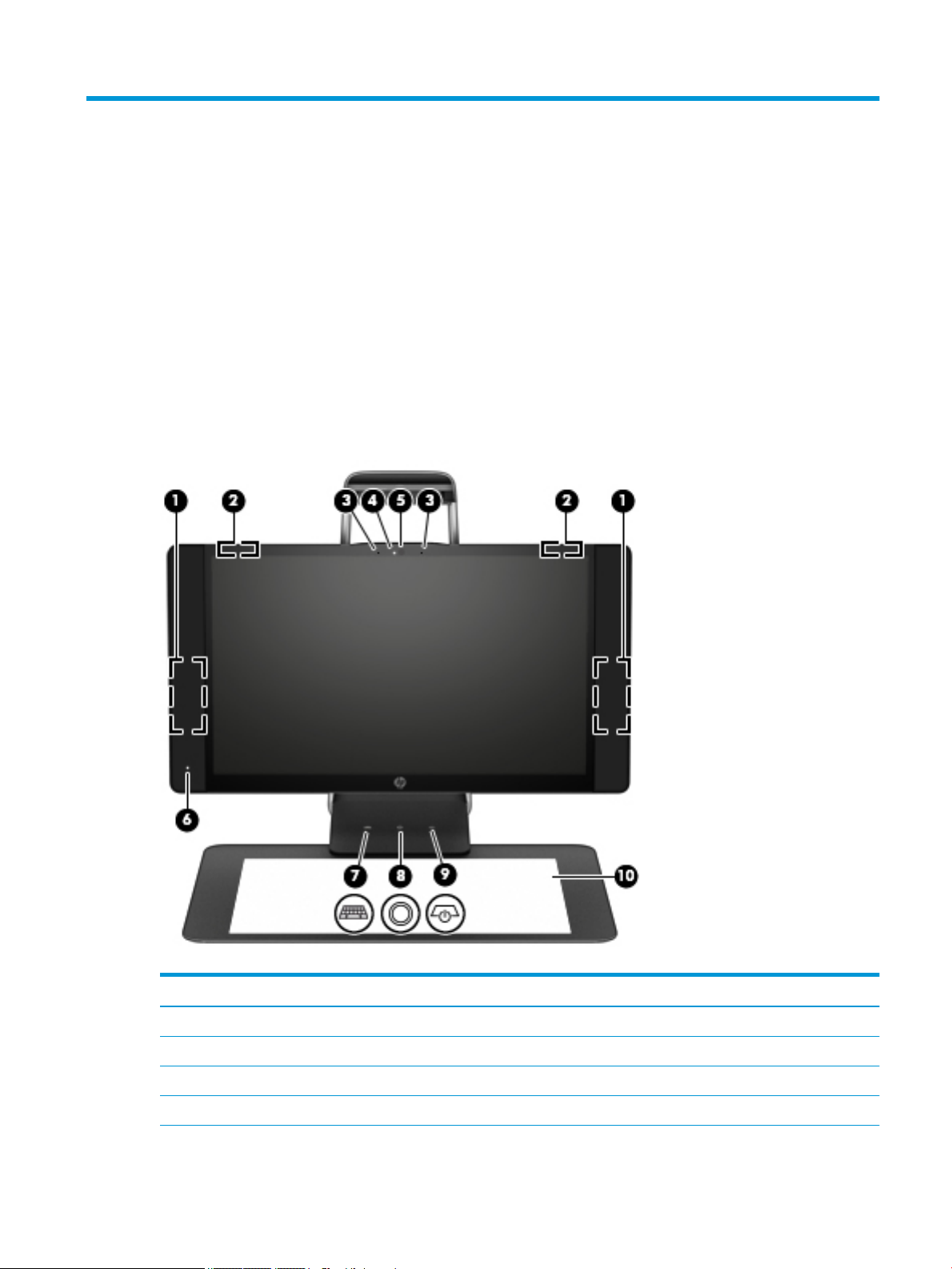
Front
Component Description
(1) Speakers (2) Produce sound.
(2) WLAN antennas (2)* Send and receive wireless signals.
(3) Internal microphones (2) Record audio, automatically ltering out the noise around you.
(4) Webcam light On: The webcam is on.
Front 1
Component Description
(5) Webcam Records video and takes still photographs.
To use the webcam:
▲ Type camera in the taskbar search box, and then select Camera.
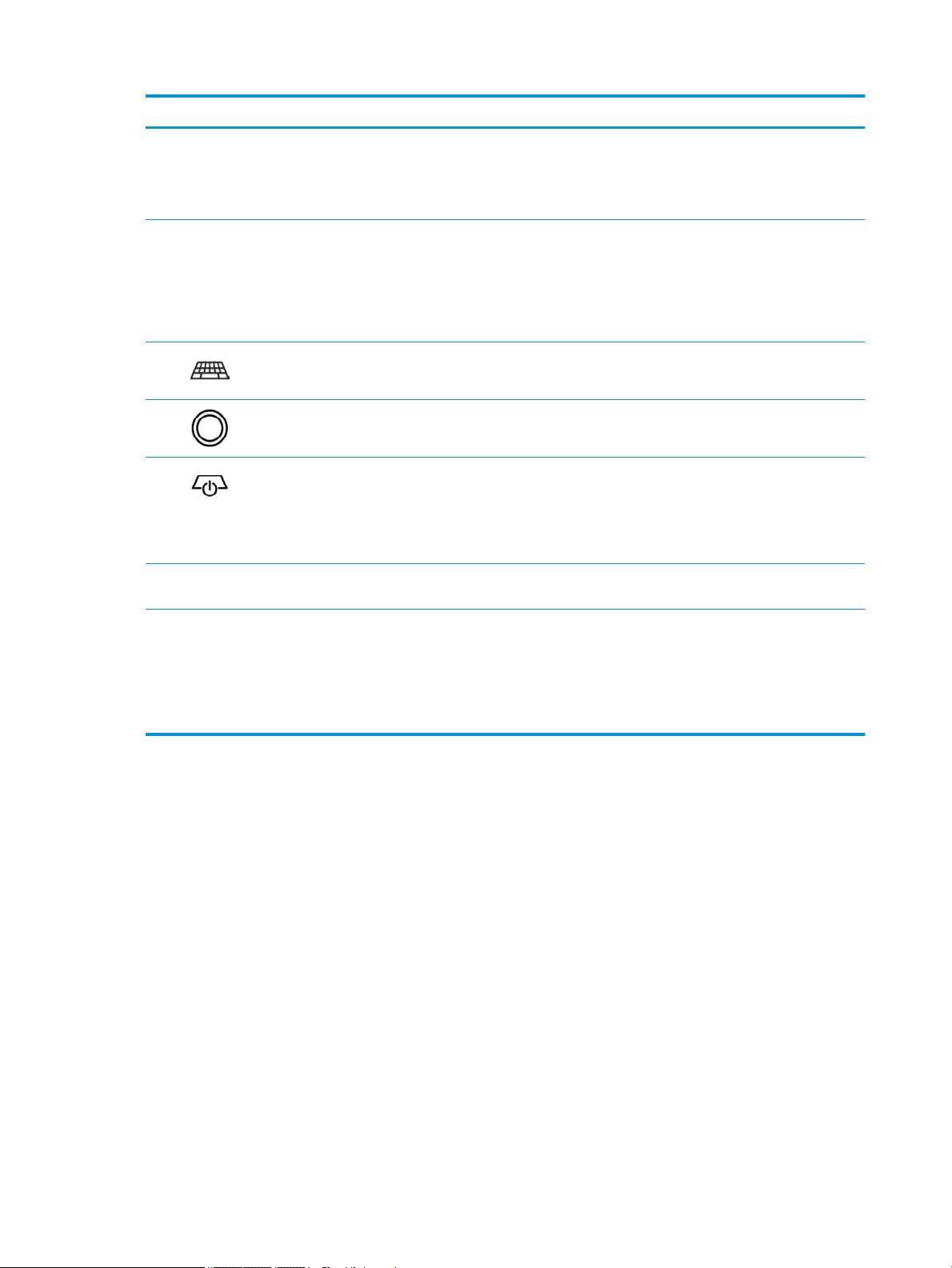
(6) Power light
(7) Keyboard button/light Projects the keyboard on the touch mat.
(8) Home button/light Displays Sprout Workspace.
(9) Projector/touch mat button/
light
(10) HP Touch Mat A touch-sensitive mat on which you can project Sprout Workspace to create a
*The antennas are not visible from the outside of the computer. For optimal transmission, keep the areas immediately around the
antennas free from obstructions. For wireless regulatory notices, see the section of the Regulatory, Safety, and Environmental Notices
that applies to your country or region.
To access this document:
●
On: The computer is on.
●
Blinking: The computer is in the Sleep state, a power-saving state. The
computer shuts o power to the display and other unneeded components.
●
O: The computer is o or in Hibernation. Hibernation is a power-saving state
that uses the least amount of power.
●
Tap the button to turn o touch capability on the mat.
●
Touch-and-hold to turn o the projector.
●
When the projector is o, tap the button to turn both the projector and the
touch mat on.
horizontal touch screen.
▲ Type support in the taskbar search box, and then select the HP Support Assistant app.
2 Chapter 1 Getting to know your Sprout
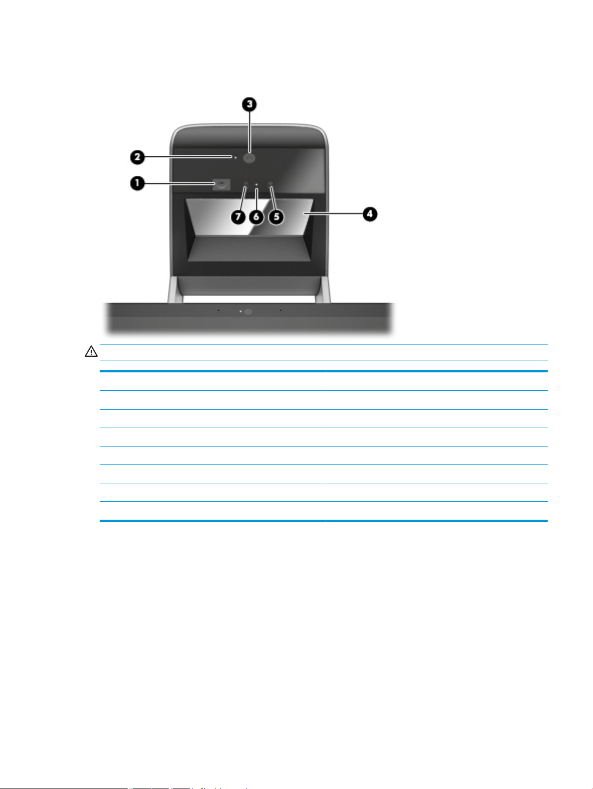
Sprout Illuminator
CAUTION: To prevent damage to your vision, avoid staring directly at the lights on Sprout Illuminator.
Component Description
(1) Desk lamp touch sensor (for depth camera) Touch to turn the desk lamp on, to dim it, or to turn it o.
(2) High-resolution camera light On: The high-resolution camera is on.
(3) High resolution camera Illuminates the touch mat.
(4) Projector mirror Projects Sprout Workspace onto the touch mat.
(5) Depth camera Captures three-dimensional images.
(6) Depth camera light On: The depth camera is on.
(7) High-resolution camera Captures high-resolution images from the touch mat.
Sprout Illuminator 3
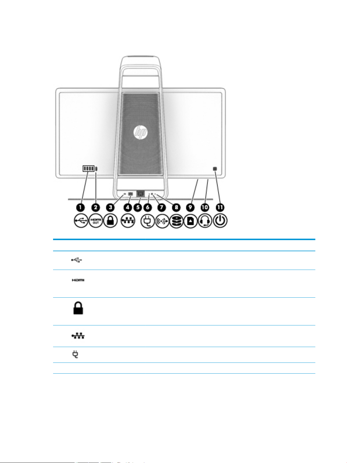
Rear
Component Description
(1) USB 3.0 ports (4) Connect optional USB 3.0 devices.
(2) HDMI output port Projects the computer screen display to an external monitor.
NOTE: The HDMI output port cannot be used as an input from a TV, a game console,
or a set top box.
(3) Security cable slot Attaches an optional security cable to the computer.
NOTE: The security cable may not prevent the computer from being mishandled or
stolen.
(4) RJ-45 (network) jack Connects a network cable.
(5) Power connector Connects a power cord.
(6) Power supply light On: The power cord is connected.
4 Chapter 1 Getting to know your Sprout
Component Description
(7) Audio-out (headphone)
jack
(8) Drive light Blinking white: The hard drive is being accessed.
(9) Memory card reader Reads optional memory cards (SD, SDHC and SDXC) that store, manage, share, or
Connects optional powered stereo speakers, headphones, earbuds, a headset, or a
television audio cable. Also connects an optional headset microphone. This jack does
not support optional microphone-only devices.
WARNING! To reduce the risk of personal injury, adjust the volume before putting on
headphones, earbuds, or a headset. For additional safety information, see the
Regulatory, Safety, and Environmental Notices.
To access this guide:
1. Type support in the taskbar search box, and then select the HP Support
Assistant app.
– or –
Click the question mark icon in the taskbar.
2. Select My PC, select the Specications tab, and then select User Guides.
NOTE: When a device is connected to the jack, the computer speakers are disabled.
access information.
To insert a card:
1. Hold the card label-side facing to the front with the connectors facing the
computer.
(10) Audio-out (headphone)/
Audio-in (microphone)
jack
2. Insert the card into the memory card reader, and then press in on the card until it
is rmly seated.
To remove a card, pull the card out from the memory reader.
Connects optional powered stereo speakers, headphones, earbuds, a headset, or a
television audio cable.
WARNING! To reduce the risk of personal injury, adjust the volume before putting on
headphones, earbuds, or a headset. For additional safety information, refer to the
Regulatory, Safety, and Environmental Notices.
To access this guide:
1. Type support in the taskbar search box, and then select the HP Support
Assistant app.
– or –
Rear 5
Component Description
Click the question mark icon in the taskbar.
2. Select My PC, select the Specications tab, and then select User Guides.
NOTE: When a device is connected to the headphone jack, the computer speakers
are disabled.
(11) Power button
●
●
●
●
CAUTION: Pressing and holding down the power button will result in the loss of
unsaved information.
If the computer has stopped responding and shutdown procedures are ineective,
press and hold the power button down for at least 5 seconds to turn o the computer.
To learn more about your power settings, see your power options.
1. Type power options in the taskbar search box, and then select Power
2. Right-click the Power Meter icon, and then select Power Options.
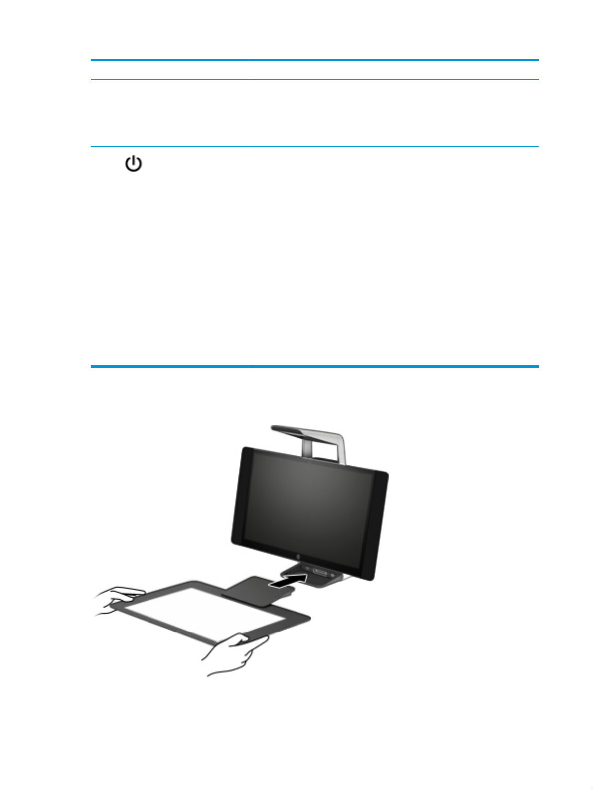
Connecting the HP Touch Mat
When the computer is o, press the button to turn on the computer.
When the computer is on, press the button briey to initiate Sleep.
When the computer is in the Sleep state, press the button briey to exit Sleep.
When the computer is in Hibernation, press the button briey to exit Hibernation.
Options
– or –
Set up your Sprout on a at, level surface.
6 Chapter 1 Getting to know your Sprout

CAUTION: To prevent damage to the touch mat:
●
Do not cut or pierce the touch mat.
●
Do not bend or fold the touch mat.
●
Do not place any magnetic components on the touch mat.
●
Do not use metal objects on or under the touch mat.
●
When using a stylus on the touch mat, do not place your hand or palm on the touch mat because your
hand or palm may be treated as contact points.
To connect the touch mat, place the touch mat on a at, level surface in front of the monitor, and slide it
toward the monitor. Magnets connect the touch mat to the monitor automatically.
NOTE: If you remove the touch mat, the projector will turn o.
To protect the touch mat from dirt or accidental damage when it is not being used, use the optional HP Touch
Mat Cover (purchased separately).
Labels
Identifying the labels
The labels axed to the computer provide information you may need when you troubleshoot system
problems. The labels are located on the bottom of the computer.
●
Service label—Provides important information to identify your computer. When contacting support, you
will probably be asked for the serial number, and possibly for the product number or the model number.
Locate these numbers before you contact support.
●
Regulatory label(s)—Provide(s) regulatory information about the computer.
●
Wireless certication label(s)—Provide(s) information about optional wireless devices and the approval
markings for the countries or regions in which the devices have been approved for use.
Labels 7

8 Chapter 1 Getting to know your Sprout
2 Illustrated parts catalog
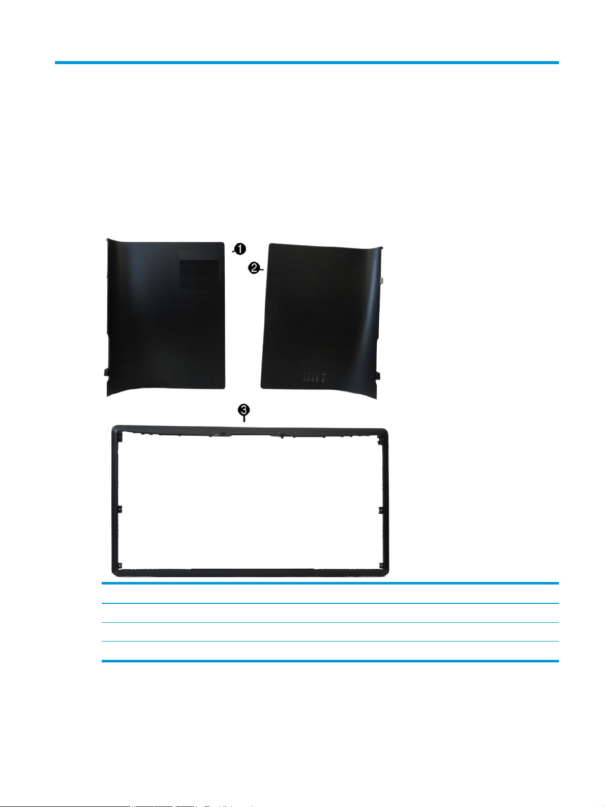
Computer covers and plastics
Item Description
(1) Left rear cover
(2) Right rear cover
(3) Outer plastic frame
Computer covers and plastics 9
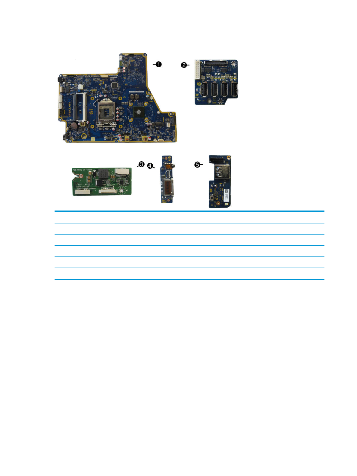
Computer boards
Item Description
(1) System board
(2) USB board
(3) Converter board
(4) Card reader/audio board
(5) Wireless receiver/power button board
10 Chapter 2 Illustrated parts catalog
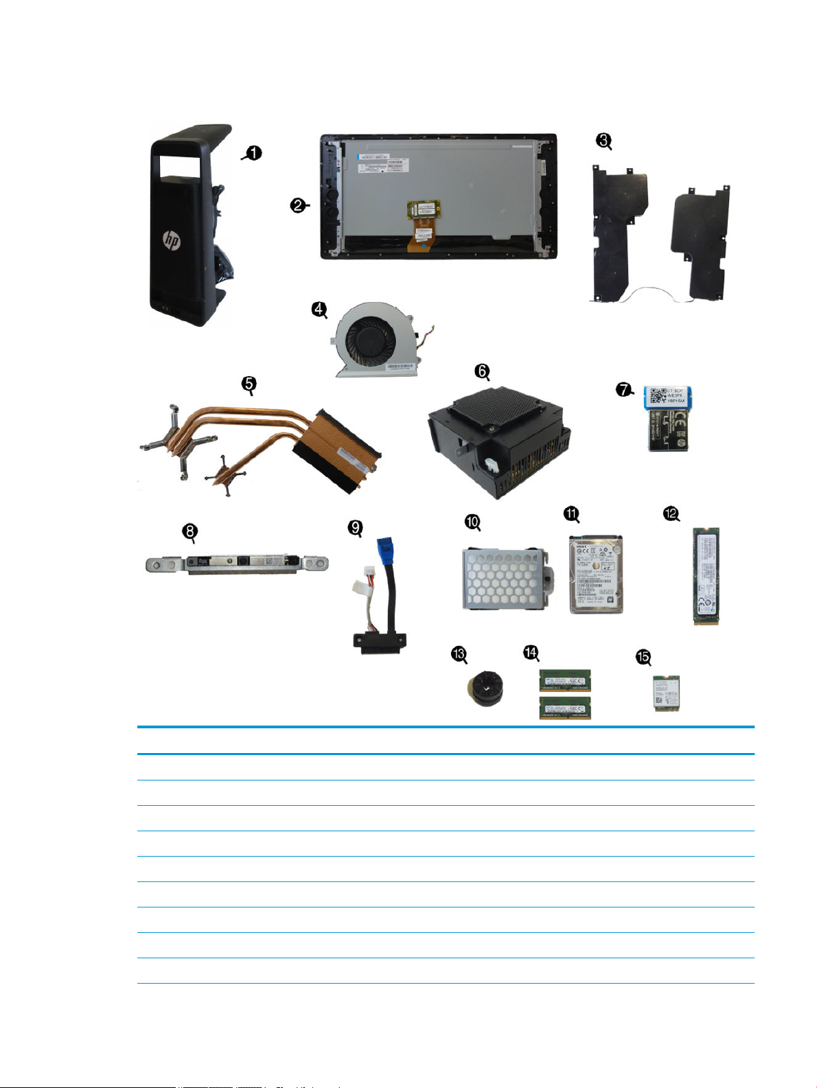
Computer miscellaneous parts
Item Description
(1) Column assembly, full assembly
(2) Display assembly, full assembly
(3) Speakers, right and left
(4) Fan
(5) Heat sink (thermal module) (includes replacement thermal material)
(6) Power supply
(7) Wireless USB receiver
(8) Webcam module assembly
(9) Hard drive connector and cables
Computer miscellaneous parts 11

Item Description
(10) Hard drive cage
(11) Hard drive (1 TB, 2.5-inch, hybrid SSHD)
(12) M.2 solid-state drives
SATA solid-state drive (512 GB, 2.5-inch)
PCIe solid-state drive (512 GB M.2 2280 NVMe PCIe; EMEA region only)
PCIe solid-state drive (256 GB M.2 2280 NVMe PCIe)
(13) Hard drive rubber screw grommet
(14) 4-GB memory module (SODIMM; PC4-2400)
(15) WLAN module (Intel Dual Band Wireless-AC 8260 NIC; 802.11abgn+ac MIMO 2x2; Bluetooth® 4.2; not illustrated)
*
*
*
*
*
*
*
not illustrated
Intel Core i7-7700T processor (2.9 GHz, 8 MB cache, 35 W) (includes replacement thermal material; not illustrated)
Antenna kit
HP Comfort Grip Wireless Mouse
Pen with app launch button
Pen keyboard loop
Touch Mat
Computer cables
Description
LVDS (display) cable
Webcam cable
Converter cable
Power/LED/wireless USB cable
LAN, rear I/O cable
Card reader/audio board cable
USB 3.0 I/O signal cable
USB 3.0 power cable
Touch USB cable
POGO USB 2.0 cable
Backlight cable
12 Chapter 2 Illustrated parts catalog

Keyboards
Description
HP Wireless Link-5 Keyboard available for the following countries:
Asia/Pacic
Belgium
Czech Republic
France
French Canada
Germany
India
Internationally
Israel
Italy
India
Japan
India
People’s Republic of China
Saudi Arabia
South Korea
Switzerland
Thailand
Turkey
United Kingdom
United States
Keyboards 13

Power cords
Description
Power cord available for the following countries and regions:
North America
Australia
Europe
India
Japan
People’s Republic of China
South Africa
South Korea
Switzerland
United Kingdom
14 Chapter 2 Illustrated parts catalog

3 Disassembly preparation and SATA drive
guidelines
This chapter provides general service information for the computer. Adherence to the procedures and
precautions described in this chapter is essential for proper service.
CAUTION: When the computer is plugged into an AC power source, voltage is always applied to the system
board. You must disconnect the power cord from the power source before opening the computer to prevent
system board or component damage.
Electrostatic discharge information
A sudden discharge of static electricity from your nger or other conductor can destroy static-sensitive
devices or microcircuitry. Often the spark is neither felt nor heard, but damage occurs. An electronic device
exposed to electrostatic discharge (ESD) may not appear to be aected at all and can work perfectly
throughout a normal cycle. The device may function normally for a while, but it has been degraded in the
internal layers, reducing its life expectancy.
Networks built into many integrated circuits provide some protection, but in many cases, the discharge
contains enough power to alter device parameters or melt silicon junctions.
Electrostatic discharge information 15

Generating static
The following table shows that:
●
Dierent activities generate dierent amounts of static electricity.
●
Static electricity increases as humidity decreases.
Relative Humidity
Event 55% 40% 10%
Walking across carpet
Walking across vinyl oor
Motions of bench worker
Removing DIPs from plastic tube
Removing DIPs from vinyl tray
Removing DIPs from Styrofoam
Removing bubble pack from PCB
Packing PCBs in foam-lined box
These are then multi-packaged inside plastic tubes, trays, or Styrofoam.
NOTE: 700 volts can degrade a product.
Preventing electrostatic damage to equipment
Many electronic components are sensitive to ESD. Circuitry design and structure determine the degree of
sensitivity. The following packaging and grounding precautions are necessary to prevent damage to electric
components and accessories.
●
To avoid hand contact, transport products in static-safe containers such as tubes, bags, or boxes.
7,500 V
3,000 V
400 V
400 V
2,000 V
3,500 V
7,000 V
5,000 V
15,000 V
5,000 V
800 V
700 V
4,000 V
5,000 V
20,000 V
11,000 V
35,000 V
12,000 V
6,000 V
2,000 V
11,500 V
14,500 V
26,500 V
21,000 V
●
Protect all electrostatic parts and assemblies with conductive or approved containers or packaging.
●
Keep electrostatic sensitive parts in their containers until they arrive at static-free stations.
●
Place items on a grounded surface before removing them from their container.
●
Always be properly grounded when touching a sensitive component or assembly.
●
Avoid contact with pins, leads, or circuitry.
●
Place reusable electrostatic-sensitive parts from assemblies in protective packaging or conductive
foam.
Personal grounding methods and equipment
Use the following equipment to prevent static electricity damage to equipment:
16 Chapter 3 Disassembly preparation and SATA drive guidelines

●
Wrist straps are exible straps with a maximum of one-megohm ± 10% resistance in the ground cords.
To provide proper ground, a strap must be worn snug against bare skin. The ground cord must be
connected and t snugly into the banana plug connector on the grounding mat or workstation.
●
Heel straps/Toe straps/Boot straps can be used at standing workstations and are compatible with
most types of shoes or boots. On conductive oors or dissipative oor mats, use them on both feet with
a maximum of one-megohm ± 10% resistance between the operator and ground.
Static Shielding Protection Levels
Method Voltage
Antistatic plastic
Carbon-loaded plastic
Metallized laminate
Grounding the work area
To prevent static damage at the work area, use the following precautions:
●
Cover the work surface with approved static-dissipative material. Provide a wrist strap connected to the
work surface and properly grounded tools and equipment.
●
Use static-dissipative mats, foot straps, or air ionizers to give added protection.
●
Handle electrostatic sensitive components, parts, and assemblies by the case or PCB laminate. Handle
them only at static-free work areas.
●
Turn o power and input signals before inserting and removing connectors or test equipment.
●
Use xtures made of static-safe materials when xtures must directly contact dissipative surfaces.
●
Keep work area free of nonconductive materials such as ordinary plastic assembly aids and Styrofoam.
●
Use eld service tools, such as cutters, screwdrivers, and vacuums, that are conductive.
1,500
7,500
15,000
Recommended materials and equipment
Materials and equipment that are recommended for use in preventing static electricity include:
●
Antistatic tape
●
Antistatic smocks, aprons, or sleeve protectors
●
Conductive bins and other assembly or soldering aids
●
Conductive foam
●
Conductive tabletop workstations with ground cord of one-megohm +/- 10% resistance
●
Static-dissipative table or oor mats with hard tie to ground
●
Field service kits
●
Static awareness labels
●
Wrist straps and footwear straps providing one-megohm +/- 10% resistance
Electrostatic discharge information 17

●
Material handling packages
●
Conductive plastic bags
●
Conductive plastic tubes
●
Conductive tote boxes
●
Opaque shielding bags
●
Transparent metallized shielding bags
●
Transparent shielding tubes
Operating guidelines
To prevent overheating and to help prolong the life of the computer:
●
Keep the computer away from excessive moisture, direct sunlight, and extremes of heat and cold.
●
Operate the computer on a sturdy, level surface. Leave a 10.2-cm (4-inch) clearance on all vented sides
of the computer and above the monitor to permit the required airow.
●
Never restrict the airow into the computer by blocking any vents or air intakes. Do not place the
keyboard, with the keyboard feet down, directly against the front of the desktop unit as this also
restricts airow.
●
Occasionally clean the air vents on all vented sides of the computer. Lint, dust, and other foreign matter
can block the vents and limit the airow. Be sure to unplug the computer before cleaning the air vents.
●
Never operate the computer with the covers or panels removed.
●
If the computer is to be operated within a separate enclosure, intake and exhaust ventilation must be
provided on the enclosure, and the same operating guidelines listed above will still apply.
●
Keep liquids away from the computer and keyboard.
●
Never cover the ventilation slots on the monitor with any type of material.
●
Install or enable power management functions of the operating system or other software, including
sleep states.
Service considerations
Listed below are some of the considerations that you should keep in mind during the disassembly and
assembly of the computer.
Fan
The fan is variable-speed based on the temperature in the computer.
CAUTION: The cooling fan is always on when the computer is in the “On” mode. The cooling fan is o when
the computer is in “Standby,” “Suspend,” or “O” modes.
You must disconnect the power cord from the power source before opening the computer to prevent system
board or component damage.
18 Chapter 3 Disassembly preparation and SATA drive guidelines

Tools and software requirements
To service the computer, you need the following:
●
Torx T-15 screwdriver
●
Flat-bladed screwdriver (may sometimes be used in place of the Torx screwdriver)
●
Phillips #1 screwdriver
●
Diagnostics software
Screws
The screws used in the computer are not interchangeable. They may have standard or metric threads and may
be of dierent lengths. If an incorrect screw is used during the reassembly process, it can damage the unit. HP
strongly recommends that all screws removed during disassembly be kept with the part that was removed,
then returned to their proper locations.
CAUTION: Metric screws have a black nish. U.S. screws have a silver nish and are used on hard drives only.
CAUTION: As each subassembly is removed from the computer, it should be placed away from the work area
to prevent damage.
Cables and connectors
Most cables used throughout the unit are at, exible cables. These cables must be handled with care to
avoid damage. Apply only the tension required to seat or unseat the cables during insertion or removal from
the connector. Handle cables by the connector whenever possible. In all cases, avoid bending or twisting the
cables, and ensure that the cables are routed in such a way that they cannot be caught or snagged by parts
being removed or replaced.
CAUTION: When servicing this computer, ensure that cables are placed in their proper location during the
reassembly process. Improper cable placement can damage the computer.
Hard Drives
Handle hard drives as delicate, precision components, avoiding all physical shock and vibration. This applies
to failed drives as well as replacement spares.
●
●
●
●
●
If a drive must be mailed, place the drive in a bubble-pack mailer or other suitable protective packaging
and label the package “Fragile: Handle With Care.”
Do not remove hard drives from the shipping package for storage. Keep hard drives in their protective
packaging until they are actually mounted in the CPU.
Avoid dropping drives from any height onto any surface.
If you are inserting or removing a hard drive, turn o the computer. Do not remove a hard drive while the
computer is on or in standby mode.
Before handling a drive, ensure that you are discharged of static electricity. While handling a drive, avoid
touching the connector.
Service considerations 19
●
Do not use excessive force when inserting a drive.
●
Avoid exposing a hard drive to liquids, temperature extremes, or products that have magnetic elds
such as monitors or speakers.
Lithium coin cell battery
The battery that comes with the computer provides power to the real-time clock and has a minimum lifetime
of about three years.
See the appropriate removal and replacement chapter for the chassis you are working on in this guide for
instructions on the replacement procedures.
WARNING! This computer contains a lithium battery. There is a risk of re and chemical burn if the battery is
handled improperly. Do not disassemble, crush, puncture, short external contacts, dispose in water or re, or
expose it to temperatures higher than 140ºF (60ºC). Do not attempt to recharge the battery.
NOTE: Batteries, battery packs, and accumulators should not be disposed of together with the general
household waste. In order to forward them to recycling or proper disposal, please use the public collection
system or return them to HP, their authorized partners, or their agents.
SATA hard drives
Serial ATA Hard Drive Characteristics
Number of pins/conductors in data cable 7/7
Number of pins in power cable 15
Maximum data cable length 39.37 in (100 cm)
Data interface voltage dierential 400-700 mV
Drive voltages 3.3 V, 5 V, 12 V
Jumpers for conguring drive N/A
Data transfer rate 6.0 Gb/s
SATA hard drive cables
SATA data cable
Always use an HP approved SATA 6.0 Gb/s cable as it is fully backwards compatible with the SATA 1.5 Gb/s
drives.
Current HP desktop products ship with SATA 6.0 Gb/s hard drives.
SATA data cables are susceptible to damage if overexed. Never crease a SATA data cable and never bend it
tighter than a 30 mm (1.18 in) radius.
The SATA data cable is a thin, 7-pin cable designed to transmit data for only a single drive.
20 Chapter 3 Disassembly preparation and SATA drive guidelines
 Loading...