

Page 1

HP Slate 500
Maintenance and Service Guide
Page 2

© Copyright 2010 Hewlett-Packard
Development Company, L.P.
Bluetooth is a trademark owned by its
proprietor and used by Hewlett- Packard
Company under license. Intel is a trademark
of Intel Corporation in the U.S. and other
countries. Microsoft, Windows, and
Windows Vista are U.S. registered
trademarks of Microsoft Corporation.
SD Logo is a trademark of its proprietor.
The information contained herein is subject
to change without notice. The only
warranties for HP products and services are
set forth in the express warranty statements
accompanying such products and services.
Nothing herein should be construed as
constituting an additional warranty. HP shall
not be liable for technical or editorial errors
or omissions contained herein.
First Edition: September 2010
Document Part Number: 633016-001
Page 3

Safety warning notice
WARNING! To reduce the possibility of heat-related injuries or of overheating the device, do not
place the device directly on your lap or obstruct the device air vents. Use the device only on a hard, flat
surface. Do not allow another hard surface, such as an adjoining optional printer, or a soft surface,
such as pillows or rugs or clothing, to block airflow. Also, do not allow the AC adapter to contact the
skin or a soft surface, such as pillows or rugs or clothing, during operation. The device and the AC
adapter comply with the user-accessible surface temperature limits defined by the International
Standard for Safety of Information Technology Equipment (IEC 60950).
iii
Page 4

iv Safety warning notice
Page 5

Table of contents
1 Product description ........................................................................................................... 1
2 External component identification ..................................................................................... 3
Identifying the hardware ........................................................................................................... 3
Top-edge components ............................................................................................................... 3
Bottom-edge components .......................................................................................................... 4
Right-edge components ............................................................................................................. 4
Opening the label tray ............................................................................................... 5
Left-edge components ............................................................................................................... 6
Buttons .................................................................................................................................... 7
Display components ................................................................................................................. 8
Rear components ..................................................................................................................... 8
Wireless antennas .................................................................................................................... 9
3 Illustrated parts catalog .................................................................................................. 10
Identifying the labels ............................................................................................................... 10
HP Slate 500 component spare part numbers ............................................................................ 12
4 Removal and replacement procedures ............................................................................ 13
Preliminary replacement requirements ....................................................................................... 13
Service considerations ............................................................................................. 13
Plastic parts ............................................................................................. 13
Cables and connectors ............................................................................. 13
Drive handling ......................................................................................... 14
Grounding guidelines .............................................................................................. 14
Electrostatic discharge damage .................................................................. 14
Packaging and transporting guidelines ....................................................... 16
Workstation guidelines ............................................................................. 16
Equipment guidelines ................................................................................ 17
Component replacement procedures ........................................................................................ 18
Identifying the labels ................................................................................................ 18
Digital pen ............................................................................................................. 19
HP Slate Dock ......................................................................................................... 20
v
Page 6

5 BIOS Setup ..................................................................................................................... 21
Starting BIOS Setup ................................................................................................................ 21
Using BIOS Setup .................................................................................................................. 21
Changing the language of BIOS Setup ...................................................................... 21
Navigating and selecting in BIOS Setup .................................................................... 22
Displaying system information ................................................................................... 22
Restoring factory settings in BIOS Setup ..................................................................... 23
Exiting BIOS Setup .................................................................................................. 23
Updating the BIOS ................................................................................................................. 24
Determining the BIOS version ................................................................................... 24
Downloading a BIOS update .................................................................................... 25
BIOS Setup Menu .................................................................................................................. 26
Main menu ............................................................................................................. 26
Diagnostics menu .................................................................................................... 26
System Configuration menu ...................................................................................... 26
6 Specifications ................................................................................................................. 27
Operating environment ........................................................................................................... 27
Input power ........................................................................................................................... 28
7 Backup and recovery ...................................................................................................... 29
Using Windows Backup and Restore ........................................................................................ 29
Using system restore points ...................................................................................................... 29
When to create restore points ................................................................................... 30
Creating a system restore point ................................................................................. 30
Restoring to a previous date and time ........................................................................ 30
8 Power cord set requirements .......................................................................................... 31
Requirements for all countries .................................................................................................. 31
Requirements for specific countries and regions ......................................................................... 32
9 Recycling ........................................................................................................................ 33
Battery .................................................................................................................................. 33
Display ................................................................................................................................. 33
Index ................................................................................................................................. 39
vi
Page 7

1 Product description
Category Description
Product Name HP Slate 500
Processor Intel® Atom Menlow Z540 1.86-GHz processor 512-KB L2 cache, 533-MHz front side bus
(FSB)
Chipset Intel Poulsbo system controller hub (SCH) US15W
Graphics Intel high-definition Broadcom video decoder (on system board) with 64 MB buffer memory
(32MB×16 DDR2×1 piece, 1.8 V @ 400 MHz) and universal memory architecture (UMA)
graphics memory subsystem
Panel 8.9-in, WSVGA (1024×600) wide-viewing angle, multitouch capacitive, Poly(methyl
methacrylate, PMMA) AntiGlare type
Memory DDR2 memory built into system board, not customer-accessible/upgradable
Memory support:
●
DDR2 800 MHz (downgrade to 533 MHz due to chipset limitation)
●
DDR2 667 MHz (downgrade to 533 MHz due to chipset limitation)
●
DDR2 533 MHz single channel support
Supports 2048-MB total system memory (2048 MB×1) on system board (8 components,
128 MB×16 chips) running at 533-MHz configuration
Primary storage Supports 64-GB solid-state drive (SSD)
Optical drives No support for internal or USB-powered optical drive
Audio and video One digital microphone
HD audio
Two integrated 1.5-W, non-branded stereo speakers
Two fixed integrated webcams:
●
User-facing webcam using OV-7740 sensor with 2-pixel, F2.4 fixed-focus low-light lens
supporting 640×480 by 24 frames per second
●
Rear-facing webcam using OV-3642 sensor with 4-pixel, F2.8 fixed-focus lens
supporting extended depth of field (EDoF) feature, 3-megapixel stills, and video up to
24 frames per second
Modem No support for modem
1
Page 8

Category Description
Ethernet No support for Ethernet
Wireless Integrated wireless local area network (WLAN) option by way of Broadcom 4313
802.11b/g/n WiFi and 2070 Bluetooth 2.1+EDR Combo adapter (Bluetooth 3.0+HS
ready)
Two WLAN antennas built into HP Slate 500
External media card Supports the following optional digital card formats:
●
Secure Digital High Capacity (SDHC) Memory Card (standard and large size)
●
xD-Picture card
Ports
Docking Supports HP Slate Dock (ports include two USB 2.0 ports, one HDMI-out port, one
Keyboard/pointing
devices
Supports USB- or Bluetooth-connected external keyboard and/or mouse
Power requirements 30-W AC adapter with localized cable plug support (AC adapter connects to the HP Slate
Supports one 2-cell, 2.80-Ah (30-Wh) Lithium-polymer battery (non-replaceable)
Security No support for security options
Operating system Preinstalled:
Serviceability No support for end-user replaceable parts
●
HP Slate 500 proprietary AC power
●
HP Slate 500 proprietary docking
●
Combination audio-in (mono microphone)/audio-out (stereo headphone)
●
USB 2.0
combination audio-in/audio-out jacks, and one power connector)
No integrated keyboard or TouchPad
500 through the HP Slate Dock)
●
Windows® 7 Professional 32
●
FreeDOS
2 Chapter 1 Product description
Page 9
2 External component identification
Identifying the hardware
Components included with the Slate may vary by region and model. The illustrations in this chapter
identify the standard features on most Slate models.
To see a list of hardware installed in the Slate:
1. Tap Start > Control Panel.
2. Tap System and Security, tap System, and then tap Device Manager.
You can also add hardware or modify Slate configurations using Device Manager.
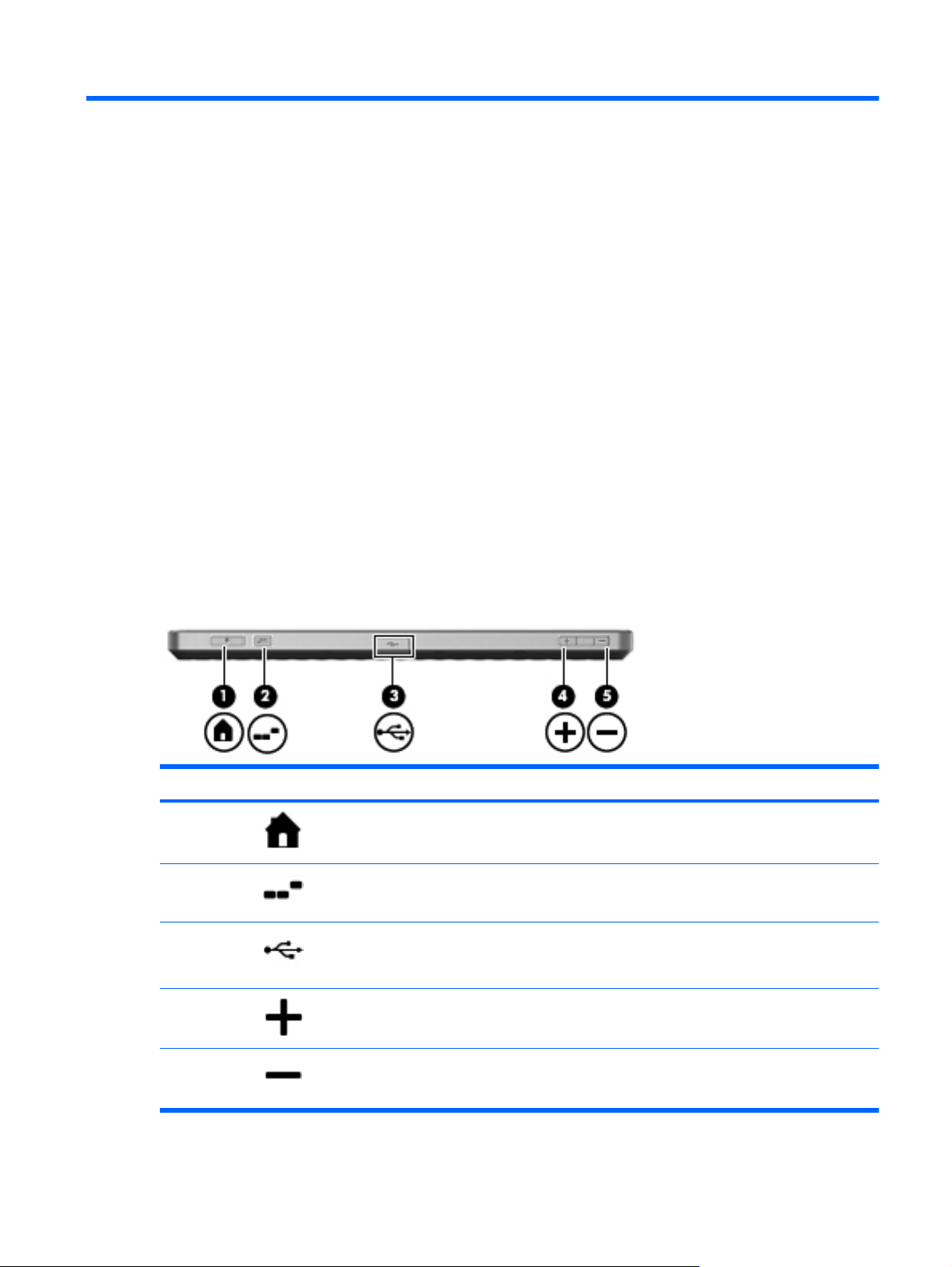
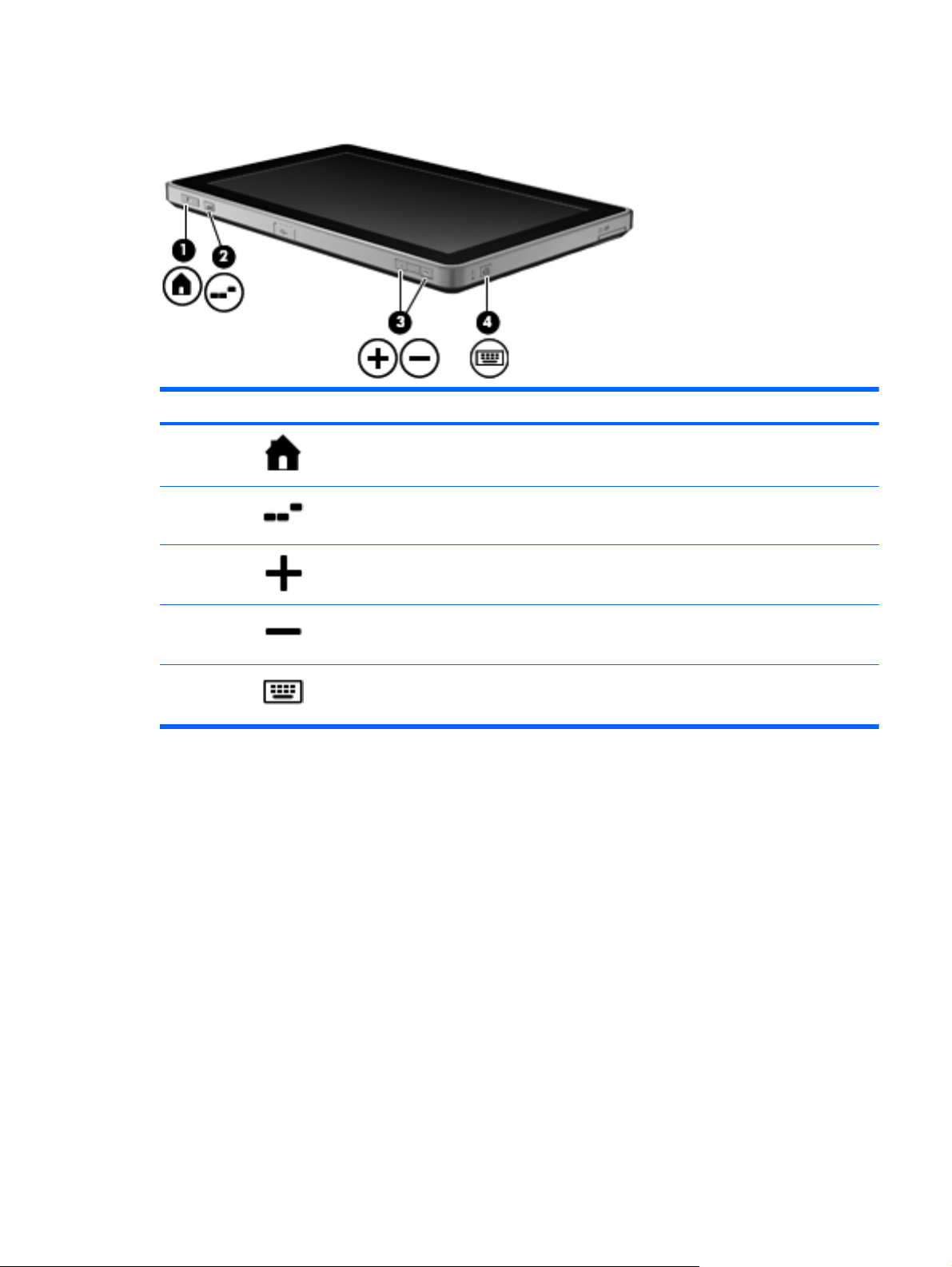
Top-edge components
Component Description
(1)
(2)
(3)
(4)
Home button Minimizes all open applications and displays the Windows desktop.
Ctrl+alt+del button Performs the same action as pressing ctrl+alt+del on a computer keyboard.
USB port Connects optional USB devices. NOTE: To use an external optical disc
Volume up button Increases speaker volume.
drive connected to the Slate, you must connect AC power separately to the
external drive.
(5)
Volume down button Decreases speaker volume.
Identifying the hardware
3
Page 10
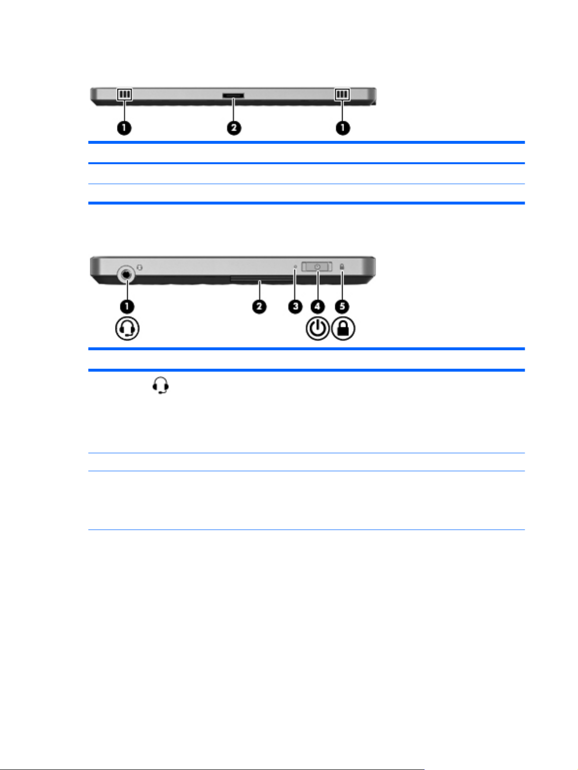
Bottom-edge components
Component Description
(1) Speakers (2) Produce sound.
(2) Power connector Connects an AC adapter or an HP Slate Dock.
Right-edge components
Component Description
(1)
(2) Label tray Holds the serial number label.
(3) Power light
Audio-out
(headphone)/Audioin (microphone)
combo jack
Produces sound when connected to optional powered stereo speakers,
headphones, earbuds, a headset, or television audio. Also connects an
optional headset microphone.
NOTE: When an audio component is connected to the jack, the Slate's
speakers are disabled. The audio component cable must have a 4conductor connector.
●
White: The Slate is on.
●
Blinking: The Slate is in the Sleep state.
●
Off: The Slate is off or in Hibernation.
4 Chapter 2 External component identification
Page 11
Component Description
(4) Power switch
(5) PowerLock icon The PowerLock feature allows you to lock the screen to avoid
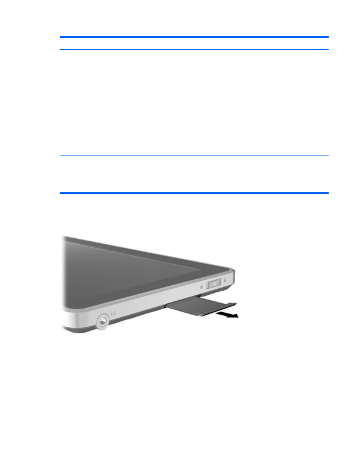
Opening the label tray
Pull the tray out to view the serial number label.
●
When the Slate is off,slide the switch down to turn on the Slate.
●
When the Slate is on, briefly slide the switch down to initiate Sleep.
●
When the Slate is in the Sleep state, briefly slide the switch down to
exit Sleep.
●
When the Slate is in Hibernation, briefly slide the switch down to
exit Hibernation.
If the Slate has stopped responding and Windows shutdown procedures
are ineffective, slide and hold the power switch down for at least five
seconds to turn off the Slate.
To learn more about your power settings, tap Start > Control Panel >
System and Security > Power Options.
accidental activation:
●
When the Slate is on, slide the power switch up to the lock position to
lock the screen, buttons, and the auto-rotate feature.
Right-edge components
5
Page 12
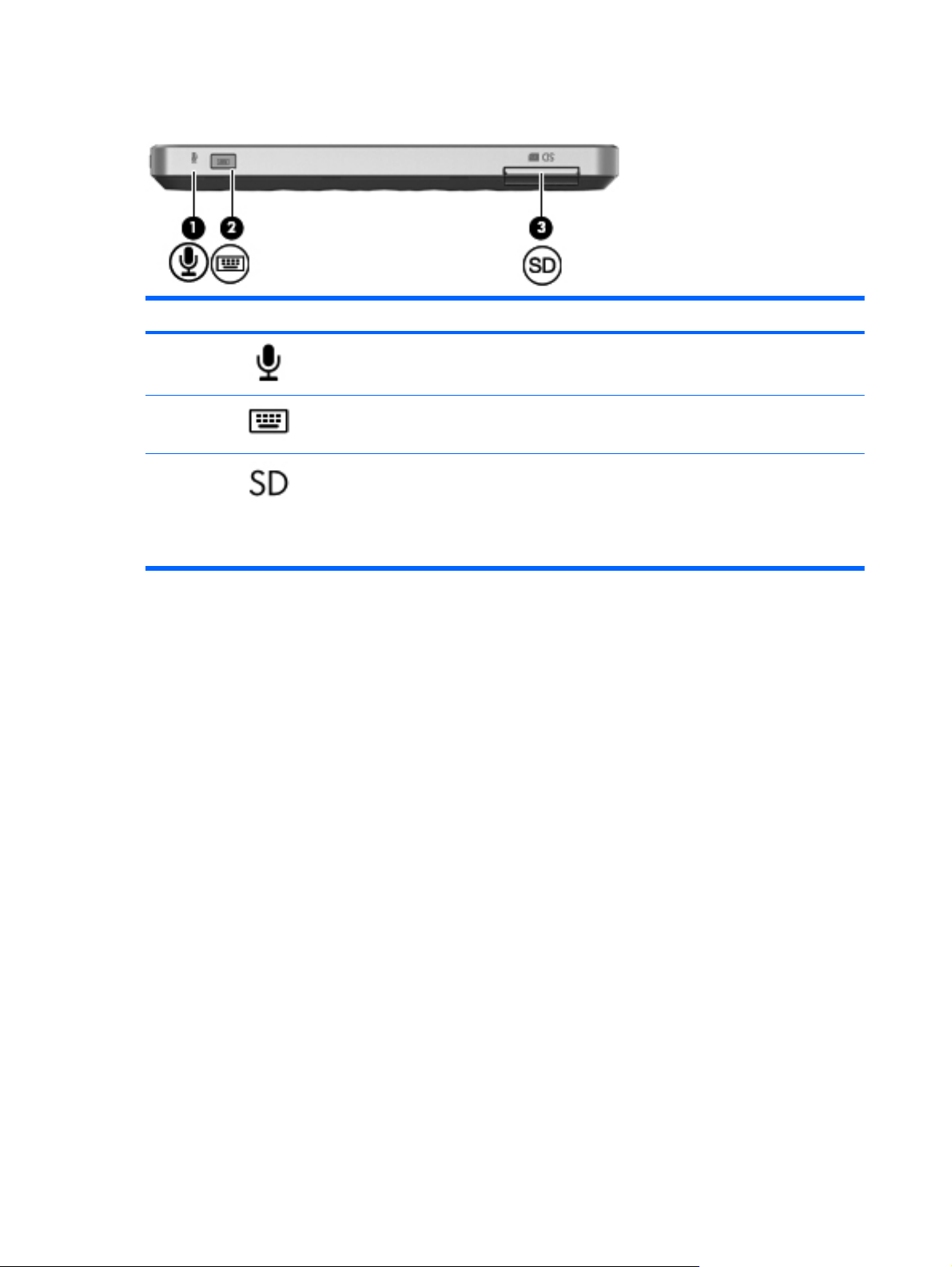
Left-edge components
Component Description
(1)
(2)
(3)
Internal microphone Records sound.
Keyboard button When the Slate is on, press the button to display the on-screen keyboard.
SD Card Reader Supports the following optional digital card formats:
●
Secure Digital High Capacity (SDHC) Memory Card (standard and
large size)
●
xD-Picture card
6 Chapter 2 External component identification
Page 13
Buttons
Component Description
(1)
(2)
(3)
(3)
(4)
Home button When the Slate is on, press the button to minimize all open applications
and display the Windows desktop.
Ctrl+alt+del button Performs the same action as pressing ctrl+alt+del on a computer keyboard.
Volume up button
Volume down button
Keyboard button When the Slate is on, press the button to display the on-screen keyboard.
●
Press + to increase speaker volume.
●
Press - to decrease speaker volume.
Buttons
7
Page 14
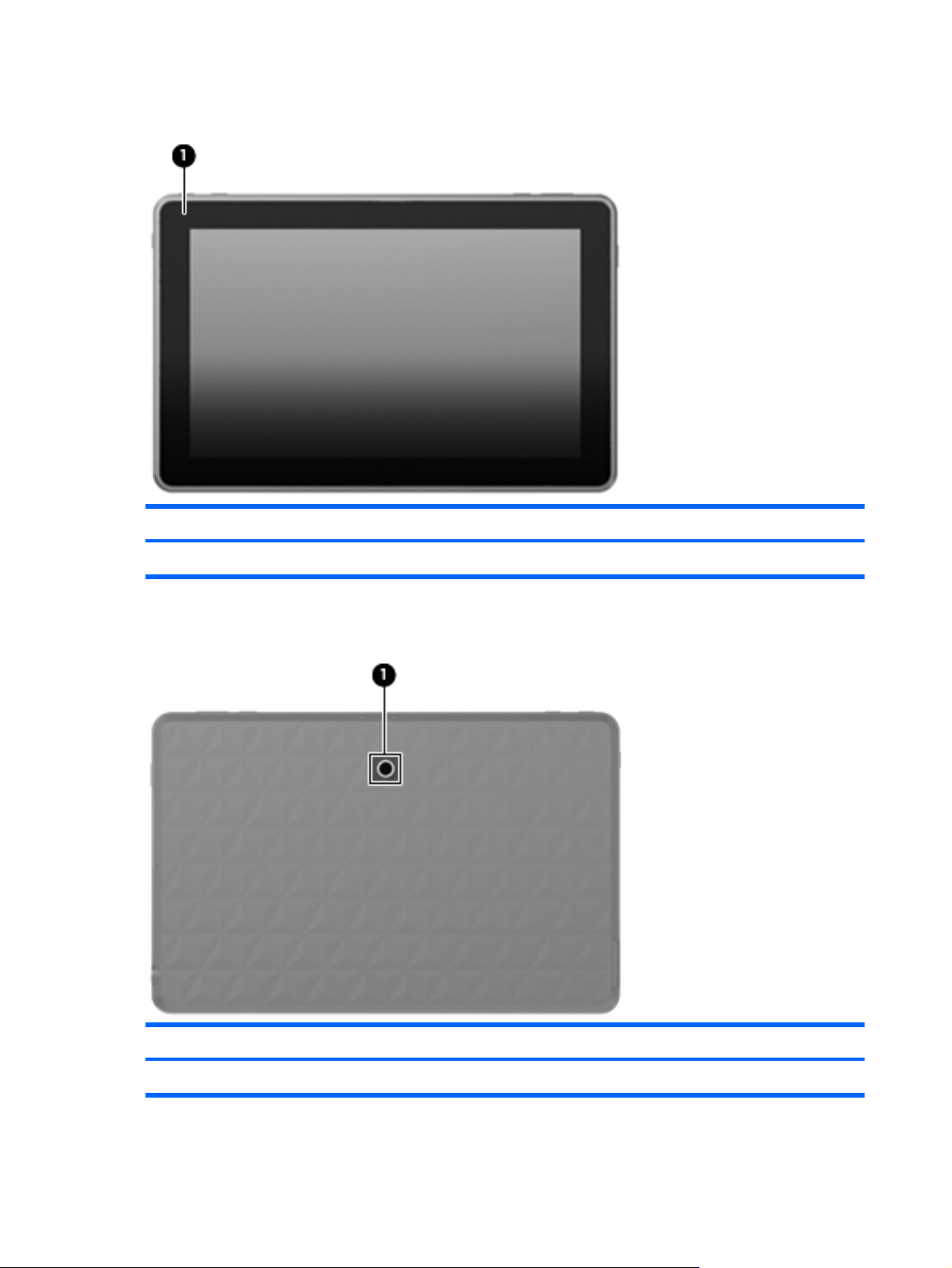
Display components
Component Description
(1) Inward camera Records video and captures still photographs.
Rear components
Component Description
(1) Outward camera Records video and captures still photographs.
8 Chapter 2 External component identification
Page 15
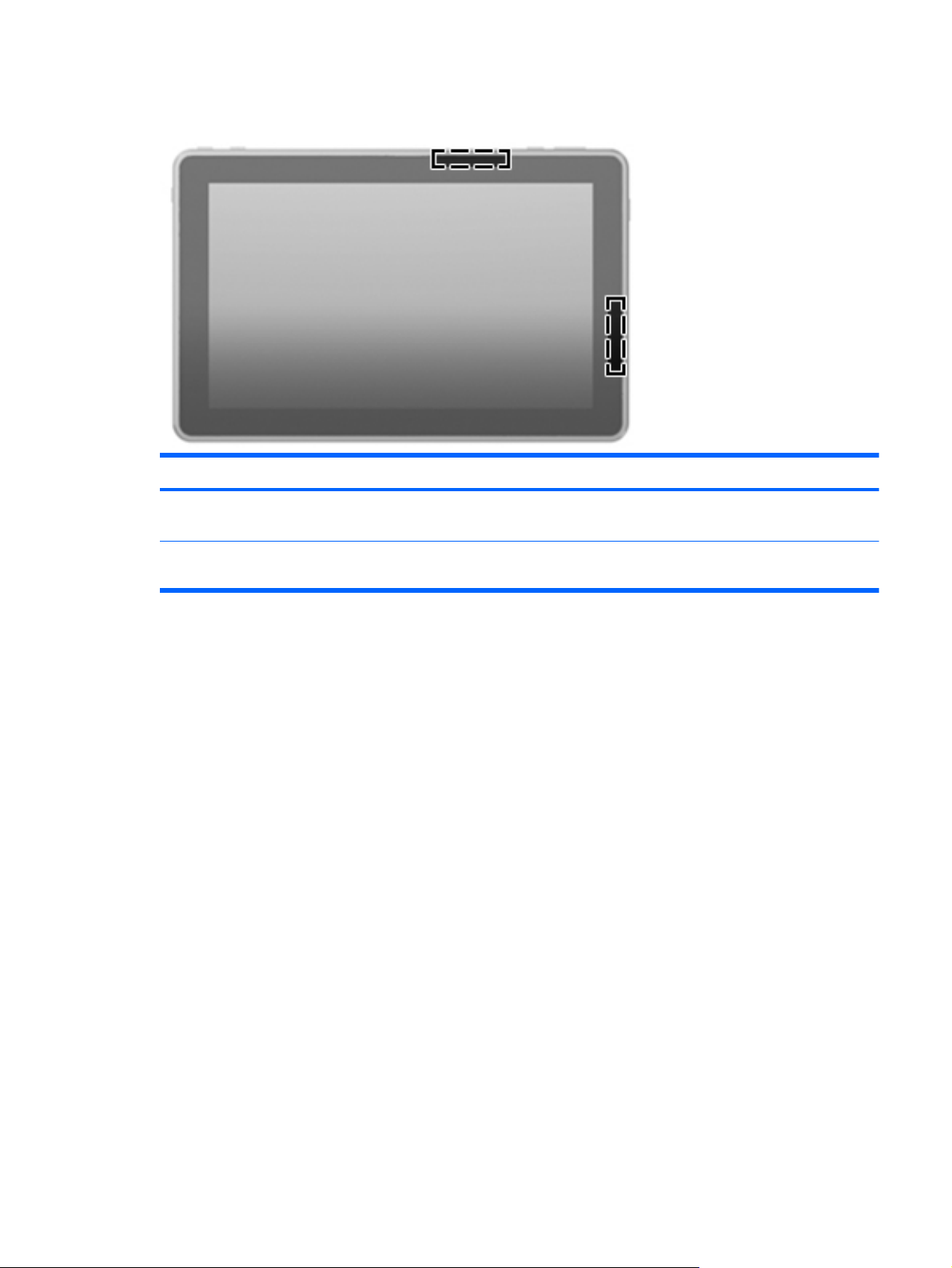
Wireless antennas
Component Description
WLAN antennas (2)* Send and receive wireless signals to communicate with wireless local-area
*The antennas are not visible from the outside of the Slate. For optimal transmission, keep the areas immediately around the
antennas free from obstructions.
networks (WLANs).
Wireless antennas
9
Page 16

3 Illustrated parts catalog
Identifying the labels
The labels affixed to the label tray of the Slate provide information you may need when you
troubleshoot system problems or travel internationally with the Slate.
●
Serial number label (part of the Master Regulatory label)—Provides important information
including the following:
◦
Product name (1). This is the product name affixed to the front of your Slate.
◦
Serial number (2). This is an alphanumeric identifier that is unique to each product.
◦
Product number (3). This is an alphanumeric identifier that provides specific information
about the hardware components. The product number helps a service technician to determine
what components and parts are needed.
10 Chapter 3 Illustrated parts catalog
Page 17

◦
Warranty period (4). This number describes the duration (in years) of the warranty period for
this Slate.
◦
Model description (select models) (5). This is an alphanumeric identifier that you use to
locate documents, drivers, and support for your Slate.
Have this information available when you contact technical support. The serial number label
is located inside the label tray of your Slate.
●
Microsoft Certificate of Authenticity—Contains the Windows Product Key. You may need the
Product Key to update or troubleshoot the operating system. This certificate is located inside the
label tray.
●
Regulatory label—Provides regulatory information about the Slate. The regulatory marks are
located on the top or the bottom of the label tray.
●
Wireless certification label(s)—Provide certification information about wireless devices, such as a
wireless local area network (WLAN) device or a Bluetooth device, and the approval markings of
some of the countries or regions in which the devices have been approved for use. You may need
this information when traveling internationally. Wireless certification labels are affixed inside the
label tray.
Identifying the labels
11
Page 18

HP Slate 500 component spare part numbers
Item Description Spare part number
(1) 30-watt AC adapter 594913-001
(2) Power cord for use in North America (1.83-meter (6-foot), 3-pin) 490371-001
(3) Black folio case 611362-001
(4) HP Slate Dock 621229-001
(5) HP Slate digital pen 611038-001
(6) RJ45-to-USB adapter cable 539614-001
HP Slate 500 (not illustrated, equipped with 2-GB of system memory and 64-GB
solid-state drive for use only in Japan and Asia-Pacific countries and regions,
not illustrated)
639693-001
12 Chapter 3 Illustrated parts catalog
Page 19

4 Removal and replacement
procedures
Preliminary replacement requirements
Service considerations
The following sections include some of the considerations that you must keep in mind during
disassembly and assembly procedures.
NOTE: As you remove each subassembly from the Slate, place the subassembly away from the work
area to prevent damage.
Plastic parts
CAUTION: Using excessive force during disassembly and reassembly can damage plastic parts. Use
care when handling the plastic parts. Apply pressure only at the points designated in the maintenance
instructions.
Cables and connectors
CAUTION: When servicing the Slate, be sure that cables are placed in their proper locations during
the reassembly process. Improper cable placement can damage the Slate.
Cables must be handled with extreme care to avoid damage. Apply only the tension required to unseat
or seat the cables during removal and insertion. Handle cables by the connector whenever possible. In
all cases, avoid bending, twisting, or tearing cables. Be sure that cables are routed in such a way that
they cannot be caught or snagged by parts being removed or replaced. Handle flex cables with
extreme care; these cables tear easily.
Preliminary replacement requirements
13
Page 20

Drive handling
CAUTION: The solid-state drive inside the Slate is a fragile component that must be handled with
care. To prevent damage to the Slate, damage to the solid-state drive, or loss of information, observe
these precautions:
Before handling the Slate, be sure that you are discharged of static electricity.
Avoid dropping the Slate from any height onto any surface.
Avoid exposing the Slate to temperature extremes or liquids.
If the Slate must be mailed, place it in a bubble pack mailer or other suitable form of protective
packaging and label the package “FRAGILE.”
Grounding guidelines
Electrostatic discharge damage
Electronic components are sensitive to electrostatic discharge (ESD). Circuitry design and structure
determine the degree of sensitivity. Networks built into many integrated circuits provide some
protection, but in many cases, ESD contains enough power to alter device parameters or melt silicon
junctions.
A discharge of static electricity from a finger or other conductor can destroy static-sensitive devices or
microcircuitry. Even if the spark is neither felt nor heard, damage may have occurred.
An electronic device exposed to ESD may not be affected at all and can work perfectly throughout a
normal cycle. Or the device may function normally for a while, then degrade in the internal layers,
reducing its life expectancy.
CAUTION: To prevent damage to the Slate when you are removing or installing internal
components, observe these precautions:
Keep components in their electrostatic-safe containers until you are ready to install them.
Before touching an electronic component, discharge static electricity by using the guidelines described
in this section.
Avoid touching pins, leads, and circuitry. Handle electronic components as little as possible.
If you remove a component, place it in an electrostatic-safe container.
The following table shows how humidity affects the electrostatic voltage levels generated by different
activities.
CAUTION: A product can be degraded by as little as 700 V.
Typical electrostatic voltage levels
Relative humidity
Event 10% 40% 55%
Walking across carpet 35,000 V 15,000 V 7,500 V
14 Chapter 4 Removal and replacement procedures
Page 21

Typical electrostatic voltage levels
Relative humidity
Event 10% 40% 55%
Walking across vinyl floor 12,000 V 5,000 V 3,000 V
Motions of bench worker 6,000 V 800 V 400 V
Removing DIPS from plastic tube 2,000 V 700 V 400 V
Removing DIPS from vinyl tray 11,500 V 4,000 V 2,000 V
Removing DIPS from Styrofoam 14,500 V 5,000 V 3,500 V
Removing bubble pack from PCB 26,500 V 20,000 V 7,000 V
Packing PCBs in foam-lined box 21,000 V 11,000 V 5,000 V
Preliminary replacement requirements
15
Page 22

Packaging and transporting guidelines
Follow these grounding guidelines when packaging and transporting equipment:
●
To avoid hand contact, transport products in static-safe tubes, bags, or boxes.
●
Protect ESD-sensitive parts and assemblies with conductive or approved containers or packaging.
●
Keep ESD-sensitive parts in their containers until the parts arrive at static-free workstations.
●
Place items on a grounded surface before removing items from their containers.
●
Always be properly grounded when touching a component or assembly.
●
Store reusable ESD-sensitive parts from assemblies in protective packaging or nonconductive
foam.
●
Use transporters and conveyors made of antistatic belts and roller bushings. Be sure that
mechanized equipment used for moving materials is wired to ground and that proper materials
are selected to avoid static charging. When grounding is not possible, use an ionizer to dissipate
electric charges.
Workstation guidelines
Follow these grounding workstation guidelines:
●
Cover the workstation with approved static-shielding material.
●
Use a wrist strap connected to a properly grounded work surface and use properly grounded tools
and equipment.
●
Use conductive field service tools, such as cutters, screwdrivers, and vacuums.
●
When fixtures must directly contact dissipative surfaces, use fixtures made only of static-safe
materials.
●
Keep the work area free of nonconductive materials, such as ordinary plastic assembly aids and
Styrofoam.
●
Handle ESD-sensitive components, parts, and assemblies by the case or PCM laminate. Handle
these items only at static-free workstations.
●
Avoid contact with pins, leads, or circuitry.
●
Turn off power and input signals before inserting or removing connectors or test equipment.
16 Chapter 4 Removal and replacement procedures
Page 23

Equipment guidelines
Grounding equipment must include either a wrist strap or a foot strap at a grounded workstation.
●
When seated, wear a wrist strap connected to a grounded system. Wrist straps are flexible straps
with a minimum of one megohm ±10% resistance in the ground cords. To provide proper ground,
wear a strap snugly against the skin at all times. On grounded mats with banana-plug connectors,
use alligator clips to connect a wrist strap.
●
When standing, use foot straps and a grounded floor mat. Foot straps (heel, toe, or boot straps)
can be used at standing workstations and are compatible with most types of shoes or boots. On
conductive floors or dissipative floor mats, use foot straps on both feet with a minimum of one
megohm resistance between the operator and ground. To be effective, the conductive must be
worn in contact with the skin.
The following grounding equipment is recommended to prevent electrostatic damage:
●
Antistatic tape
●
Antistatic smocks, aprons, and sleeve protectors
●
Conductive bins and other assembly or soldering aids
●
Nonconductive foam
●
Conductive tabletop workstations with ground cords of one megohm resistance
●
Static-dissipative tables or floor mats with hard ties to the ground
●
Field service kits
●
Static awareness labels
●
Material-handling packages
●
Nonconductive plastic bags, tubes, or boxes
●
Metal tote boxes
●
Electrostatic voltage levels and protective materials
The following table lists the shielding protection provided by antistatic bags and floor mats.
Material Use Voltage protection level
Antistatic plastics Bags 1,500 V
Carbon-loaded plastic Floor mats 7,500 V
Metallized laminate Floor mats 5,000 V
Preliminary replacement requirements
17
Page 24

Component replacement procedures
Identifying the labels
The labels affixed to the label tray of the Slate provide information you may need when you
troubleshoot system problems or travel internationally with the Slate.
●
Serial number label (part of the Master Regulatory label)—Provides important information
including the following:
◦
Product name (1). This is the product name affixed to the front of your Slate.
◦
Serial number (2). This is an alphanumeric identifier that is unique to each product.
◦
Product number (3). This is an alphanumeric identifier that provides specific information
about the hardware components. The product number helps a service technician to determine
what components and parts are needed.
◦
Warranty period (4). This number describes the duration (in years) of the warranty period for
this Slate.
◦
Model description (select models) (5). This is an alphanumeric identifier that you use to
locate documents, drivers, and support for your Slate.
18 Chapter 4 Removal and replacement procedures
Page 25

●
Microsoft Certificate of Authenticity—Contains the Windows Product Key. You may need the
Product Key to update or troubleshoot the operating system. This certificate is located inside the
label tray.
●
Regulatory label—Provides regulatory information about the Slate. The regulatory marks are
located on the top or the bottom of the label tray.
●
Wireless certification label(s)—Provide certification information about wireless devices, such as a
wireless local area network (WLAN) device or a Bluetooth device, and the approval markings of
some of the countries or regions in which the devices have been approved for use. You may need
this information when traveling internationally. Wireless certification labels are affixed inside the
label tray.
Digital pen
Description Spare part number
Digital pen 611038-001
To insert the battery into the pen:
Have this information available when you contact technical support. The serial number label
is located inside the label tray of your Slate.
1. Unscrew the cap from the pen.
2. Insert the battery (1) in the pen.
3. Replace the cap (2) on the pen.
4. Turn the cap in a clockwise direction (3) to tighten it.
Component replacement procedures
19
Page 26

HP Slate Dock
Description Spare part number
HP Slate Dock 621229-001
To dock the HP Slate to the HP Slate Dock:
1. Align the docking connector on the HP Slate Dock base with the power connector on the bottom
edge of the HP Slate, and then lower the Slate onto the dock.
2. Plug the AC adapter into the power connector on the back of the HP Slate Dock.
3. Plug the power cord into the AC adapter.
4.
Plug the other end of the power cord into an AC outlet.
Reverse this procedure to undock the HP Slate from the HP Slate Dock and disconnect the AC adapter
and power cord.
20 Chapter 4 Removal and replacement procedures
Page 27

5BIOS Setup
Starting BIOS Setup
BIOS Setup is a ROM-based information and customization utility that can be used even when your
Windows operating system is not working.
The utility reports information about the Slate and provides settings for startup, security, and other
preferences.
To start BIOS Setup:
NOTE: An external keyboard may be connected to the USB port to perform these steps.
1. Open the Startup Menu by turning on or restarting the Slate, and then, while the hyphen is
displayed in the upper-left corner of the screen, repeatedly pressing the Volume down button (-) on
the Slate or f10 on an external keyboard.
2. Press the Volume down button (-) on the Slate to advance to BIOS Setup, and then select it by
pressing the Home button on the Slate or enter on an external keyboard.
Using BIOS Setup
Changing the language of BIOS Setup
The following procedure explains how to change the language of BIOS Setup. If BIOS Setup is not
already running, begin at step 1. If BIOS Setup is already running, begin at step 3.
NOTE: An external keyboard may be connected to the USB port to perform these steps.
1. Open the Startup Menu by turning on or restarting the Slate, and then, while the hyphen is
displayed in the upper-left corner of the screen, repeatedly pressing the Volume down button (-) on
the Slate or f10 on an external keyboard.
2. Press the Volume down button (-) on the Slate, or use the arrow keys on an external keyboard to
advance to BIOS Setup, and then select it by pressing the Home button on the Slate or enter on an external keyboard.
3. Press the Volume up button (+) or the Volume down button (-) on the Slate, or use the arrow keys
on an external keyboard to select System Configuration > Language, and then press the
Home button on the Slate or enter on an external keyboard.
Starting BIOS Setup
21
Page 28

4.
Press the Volume up button (+) or Volume down button (-) on the Slate or the arrow keys on an
external keyboard to select a language, and then press the Home button on the Slate or enter on
an external keyboard.
5. To save your changes and exit BIOS Setup, press the Ctrl+alt+del button on the top edge of the
Slate, or use the arrow keys on an external keyboard to select Exit > Exit Saving Changes.
Then press the Home button on the Slate or enter on an external keyboard.
Your change goes into effect immediately.
Navigating and selecting in BIOS Setup
Because BIOS Setup is not Windows based, it does not support the touch screen. Navigation and
selection are by keystroke.
NOTE: An external keyboard may be connected to the USB port to perform these steps.
●
To choose a menu or a menu item, press the Home button on the Slate, or use the arrow keys on
an external keyboard.
●
To navigate between menus in BIOS Setup, press the Home button and the Volume up (+) or
Volume down (-) button simultaneously, or use the arrow keys on an external keyboard.
●
To choose an item in a list or to toggle a field, for example an Enable/Disable field, use either the
Home button, the Volume up button, or the Volume down button on the Slate, or the arrow keys on
an external keyboard.
●
To select an item, press the Home button on the Slate or the enter key on an external keyboard.
●
To close a text box or return to the menu display, press the Ctrl+alt+del (Security) button on the top
edge of the Slate or esc on an external keyboard.
●
Information about navigation keys is displayed at the bottom of the screen. To display additional
navigation and selection information while BIOS Setup is open, press f1 on an external keyboard.
Displaying system information
The following procedure explains how to display system information in BIOS Setup. If BIOS Setup is not
open, begin at step 1. If BIOS Setup is open, begin at step 3.
NOTE: An external keyboard may be connected to the USB port to perform these steps.
1. Open the Startup Menu by turning on or restarting the Slate, and then, while the hyphen is
displayed in the upper-left corner of the screen, repeatedly pressing the Volume down button (-) on
the Slate or f10 on an external keyboard.
2. Press the Volume down button (-) on the Slate, or use the arrow keys on an external keyboard, to
advance to BIOS Setup, and then select it by pressing the Home button on the Slate or enter on
an external keyboard.
3. If BIOS Setup does not open with the system information displayed, press the Home button and the
Volume up button (+) on the Slate simultaneously, or use the arrow keys on an external keyboard,
to select the Main menu.
22 Chapter 5 BIOS Setup
Page 29

When the Main menu is selected, system information is displayed.
4. To exit BIOS Setup without changing any settings, press the Ctrl+alt+del (Security) button on the
top edge of the Slate or the arrow keys on an external keyboard to select Exit > Exit
Discarding Changes. Then press the Home button on the Slate or the enter key on an external
keyboard.
Restoring factory settings in BIOS Setup
The following procedure explains how to restore the BIOS Setup factory settings. If BIOS Setup is not
already running, begin at step 1. If BIOS Setup is already running, begin at step 3.
NOTE: An external keyboard may be connected to the USB port to perform these steps.
1. Open the Startup Menu by turning on or restarting the Slate, and then, while the hyphen is
displayed in the upper-left corner of the screen, repeatedly pressing the Volume down button (-) on
the Slate or f10 on an external keyboard.
2.
Press the Volume down button (-) on the Slate, or use the arrow keys on an external keyboard, to
advance to BIOS Setup, and then select it by pressing the Home button on the Slate or enter on
an external keyboard.
3. Press the Home button and the Volume up button (+) on the Slate simultaneously or the arrow keys
on an external keyboard to select Exit > Load Setup Defaults. Then press the Home button on
the Slate or the enter key on an external keyboard.
4. When the Setup Confirmation is displayed, press the Home button on the Slate or the enter key on
an external keyboard.
5. To save your changes and exit BIOS Setup, press the Ctrl+alt+del (Security) button on the top
edge of the Slate, or use the arrow keys on an external keyboard, to select Exit > Exit Saving
Changes. Then press the Home button on the Slate or the enter key on an external keyboard.
The BIOS Setup factory settings go into effect when the Slate restarts.
NOTE: Your password, security, and language settings are not changed when you restore the factory
default settings.
Exiting BIOS Setup
You can exit BIOS Setup with or without saving changes.
NOTE: An external keyboard may be connected to the USB port to perform these steps.
●
To exit BIOS Setup and save your changes from the current session:
Press the Ctrl+alt+del (Security) button on the top edge of the Slate, or use the arrow keys on an
external keyboard, to select Exit > Exit Saving Changes. Then press the Home button on the
Slate or the enter key on an external keyboard.
●
To exit BIOS Setup without saving your changes from the current session:
Using BIOS Setup
23
Page 30

Press the Ctrl+alt+del (Security) button on the top edge of the Slate, or use the arrow keys on an
external keyboard, to select Exit > Exit Discarding Changes. Then press the Home button on
the Slate or the enter key on an external keyboard.
After either choice, the Slate restarts in Windows.
Updating the BIOS
Updated versions of the software provided with your Slate may be available on the HP Web site.
Most BIOS updates on the HP Web site are packaged in compressed files called SoftPaqs.
Some download packages contain a file named Readme.txt, which contains information regarding
installing and troubleshooting the file.
Determining the BIOS version
To determine whether available BIOS updates contain later BIOS versions than those currently installed
on the Slate, you need to know the version of the system BIOS currently installed.
BIOS version information (also known as ROM date and System BIOS) can be displayed by opening
BIOS Setup.
To display the BIOS information:
NOTE: An external keyboard may be connected to the USB port to perform these steps.
1. Open the Startup Menu by turning on or restarting the Slate, and then, while the hyphen is
displayed in the upper-left corner of the screen, repeatedly pressing the Volume down button (-) on
the Slate or f10 on an external keyboard.
2. Press the Volume down button (-) on the Slate, or use the arrow keys on an external keyboard, to
advance to BIOS Setup, and then select it by pressing the Home button on the Slate or enter on an
external keyboard.
3.
If BIOS Setup does not open with the system information displayed, press the Home button and the
Volume up button (+) on the Slate simultaneously, or use the arrow keys on an external keyboard,
to select the Main menu.
When the Main menu is selected, BIOS and other system information is displayed.
4. To exit BIOS Setup without saving your changes from the current session:
Press the Ctrl+alt+del (Security) button on the top edge of the Slate, or use the arrow keys on an
external keyboard, to select Exit > Exit Discarding Changes. Then press the Home button on
the Slate or the enter key on an external keyboard.
24 Chapter 5 BIOS Setup
Page 31

Downloading a BIOS update
CAUTION: To reduce the risk of damage to the Slate or an unsuccessful installation, download and
install a BIOS update only when the Slate is connected to reliable external power using the AC
adapter. Do not download or install a BIOS update while the Slate is running on battery power,
docked in an optional docking device, or connected to an optional power source. During the
download and installation, follow these instructions:
Do not disconnect power from the Slate by unplugging the power cord from the AC outlet.
Do not shut down the Slate or initiate Sleep or Hibernation.
Do not insert, remove, connect, or disconnect any device, cable, or cord.
To download a BIOS update:
1. Access the updates on the HP Web site at
2. Follow the on-screen instructions to identify your Slate and access the BIOS update you want to
download.
3. At the download area, follow these steps:
a. Identify the BIOS update that is later than the BIOS version currently installed on your Slate.
Make a note of the date, name, or other identifier. You may need this information to locate
the update later, after it has been downloaded to your hard drive.
b. Follow the instructions on the screen to download your selection to the hard drive.
Make a note of the path to the location on your hard drive where the BIOS update is to be
downloaded. You will need to access this path when you are ready to install the update.
NOTE: If you connect your Slate to a network, consult the network administrator before installing
any software updates, especially system BIOS updates.
BIOS installation procedures vary. Follow any instructions that are displayed on the screen after the
download is complete. If no instructions are displayed, follow these steps:
1. Open Windows Explorer by tapping Start > Computer.
2. Double-tap your hard drive designation. The hard drive designation is typically Local Disk (C:).
http://www.hp.com.
3. Using the hard drive path you recorded earlier, open the folder on your hard drive that contains
the update.
4.
Double-tap the file that has an .exe extension (for example, filename.exe).
The BIOS installation begins.
5. Complete the installation by following the instructions on the screen.
NOTE: After a message on the screen reports a successful installation, you can delete the
downloaded file from your hard drive.
Updating the BIOS
25
Page 32

BIOS Setup Menu
The tables in this section provide an overview of the BIOS Setup menu options.
NOTE: Some of the BIOS Setup menu items listed in this chapter may not be supported by your Slate
Main menu
Select To do this
System information
Diagnostics menu
Select To do this
Primary Hard Disk Self Test Run a quick or comprehensive self-test on the hard drive.
Memory Test Run a diagnostic test on the system memory.
System Configuration menu
Select To do this
Language Change the display language for BIOS Setup.
Virtualization Technology Enable or disable. HP recommends that this feature remain
●
View and change the system time and date.
●
View identification information about the Slate.
●
View specification information about the processor,
memory size, and system BIOS.
disabled unless specialized applications are being used.
USB Legacy Enable or disable a USB keyboard, disk, or drive to be used
Processor deeper power saving states Enable or disable.
Boot Options
26 Chapter 5 BIOS Setup
in BIOS Setup.
●
POST HotKey Delay—Select 0, 5, 10, 15, or 20
seconds to allow more time to press a hotkey to enter
BIOS Setup when the Slate restarts.
●
Boot Order options —Select the order in which the Slate
searches for a boot disk.
Page 33

6 Specifications
Operating environment
The operating environment information in the following table may be helpful if the Slate will be used in
or transported to in extreme environments.
Metric U.S.
Dimensions
Depth 23.39 cm 9.21 in
Width 14.98 cm 5.90 in
Height 1.47 cm 0.58 in
Weight 0.78 kg 1.72 lbs
Temperature
Operating 5°C to 35°C 41°F to 95°F
Nonoperating -20°C to 65°C -4°F to 149°F
Relative humidity (noncondensing)
Operating 10% to 90%
Nonoperating 5% to 90%
Maximum altitude (unpressurized)
Operating -15 m to 3,048 m -50 ft to 10,000 ft
Nonoperating -15 m to 12,192 m -50 ft to 40,000 ft
Operating environment
27
Page 34

Input power
The power information in this section may be helpful if the Slate will be used internationally.
The Slate operates on DC power, which can be supplied by an AC or a DC power source.
The AC power source must be rated at 100–240 V, 50–60 Hz.
Although the Slate can be powered from a standalone DC power source, it should be powered only
with an AC adapter or a DC power source supplied and approved by HP for use with this Slate.
The Slate is capable of accepting DC power within the following specifications.
Input power Rating
Operating voltage and current 19 V dc @ 1.58 A - 30 W (Country- or region-specific AC power cords)
NOTE: This product is designed for IT power systems in Norway with phase-to-phase voltage not
exceeding 240 V rms.
NOTE: The Slate operating voltage and current can be found on the system regulatory label, located
inside the label tray on the right edge of the Slate.
28 Chapter 6 Specifications
Page 35

7 Backup and recovery
To protect your information, back up your files and folders. In case of system failure, you can use the
backup files to restore your Slate.
Using Windows Backup and Restore
To create a backup using Windows Backup and Restore, follow these steps:
NOTE: Be sure that the Slate is connected to AC power before you start the backup process.
NOTE: The backup process may take over an hour, depending on file size and the speed of the
Slate.
1. Tap Start, tap All Programs, tap Maintenance, and then tap Backup and Restore.
2. Follow the on-screen instructions to set up and create a backup.
NOTE: Windows includes the User Account Control feature to improve the security of your Slate.
You may be prompted for your permission or password for tasks such as installing software,
running utilities, or changing Windows settings. Refer to Help and Support for more information.
Using system restore points
NOTE: “Hard drive” references in this chapter refer to the flash memory drive.
When you back up your system, you are creating a system restore point. A system restore point allows
you to save and name a snapshot of your hard drive at a specific point in time. You can then revert
back to that point if you want to reverse subsequent changes made to your system.
NOTE: Recovering to an earlier restore point does not affect data files saved or e-mails created since
the last restore point.
You also can create additional restore points to provide increased protection for your system files and
settings.
Using Windows Backup and Restore
29
Page 36

When to create restore points
●
Before you add or extensively modify software or hardware.
●
Periodically, whenever the system is performing optimally.
NOTE: If you revert to a restore point and then change your mind, you can reverse the restoration.
Creating a system restore point
1. Tap Start, tap Control Panel, tap System and Security, and then tap System.
2.
In the left pane, tap System protection.
3.
Tap the System Protection tab.
4.
Under Protection Settings, select the disk for which you want to create a restore point.
5.
Tap Create.
6.
Follow the on-screen instructions.
Restoring to a previous date and time
To revert to a restore point (created at a previous date and time) when the Slate was functioning
optimally, follow these steps:
1. Tap Start, tap Control Panel, tap System and Security, and then tap System.
2. In the left pane, tap System protection.
3. Tap the System Protection tab.
4.
Tap System Restore.
5. Follow the on-screen instructions.
30 Chapter 7 Backup and recovery
Page 37

8 Power cord set requirements
The wide-range input feature of the computer permits it to operate from any line voltage from 100 to
120 volts AC, or from 220 to 240 volts AC
The 3-conductor power cord set included with the computer meets the requirements for use in the
country or region where the equipment is purchased.
Power cord sets for use in other countries and regions must meet the requirements of the country or
region where the computer is used.
Requirements for all countries
The following requirements are applicable to all countries and regions:
●
The length of the power cord set must be at least 1.5 m (5.0 ft) and no more than 2.0 m (6.5 ft).
●
All power cord sets must be approved by an acceptable accredited agency responsible for
evaluation in the country or region where the power cord set will be used.
●
The power cord sets must have a minimum current capacity of 10 amps and a nominal voltage
rating of 125 or 250 V AC, as required by the power system of each country or region.
●
The appliance coupler must meet the mechanical configuration of an EN 60 320/IEC 320
Standard Sheet C13 connector for mating with the appliance inlet on the back of the computer.
Requirements for all countries
31
Page 38

Requirements for specific countries and regions
Country/region Accredited agency Applicable note number
Australia EANSW 1
Austria OVE 1
Belgium CEBC 1
Canada CSA 2
Denmark DEMKO 1
Finland FIMKO 1
France UTE 1
Germany VDE 1
Italy IMQ 1
Japan METI 3
The Netherlands KEMA 1
Norway NEMKO 1
The People's Republic of China COC 5
South Korea EK 4
Sweden SEMKO 1
Switzlerland SEV 1
Taiwan BSMI 4
The United Kingdom BSI 1
The United States UL 2
1. The flexible cord must be Type HO5VV-F, 3-conductor, 1.0-mm² conductor size. Power cord set fittings (appliance coupler
and wall plug) must bear the certification mark of the agency responsible for evaluation in the country or region where it
will be used.
2. The flexible cord must be Type SPT-3 or equivalent, No. 18 AWG, 3-conductor. The wall plug must be a two-pole
grounding type with a NEMA 5-15P (15 A, 125 V) or NEMA 6-15P (15 A, 250 V) configuration.
3. The appliance coupler, flexible cord, and wall plug must bear a “T” mark and registration number in accordance with the
Japanese Dentori Law. The flexible cord must be Type VCT or VCTF, 3-conductor, 1.00-mm² conductor size. The wall plug
must be a two-pole grounding type with a Japanese Industrial Standard C8303 (7 A, 125 V) configuration.
4. The flexible cord must be Type RVV, 3-conductor, 0.75-mm² conductor size. Power cord set fittings (appliance coupler
and wall plug) must bear the certification mark of the agency responsible for evaluation in the country or region where it
will be used.
5. The flexible cord must be Type VCTF, 3-conductor, 0.75-mm² conductor size. Power cord set fittings (appliance coupler
and wall plug) must bear the certification mark of the agency responsible for evaluation in the country or region where it
will be used.
32 Chapter 8 Power cord set requirements
Page 39

9 Recycling
Battery
When a battery has reached the end of its useful life, do not dispose of the battery in general
household waste. Follow the local laws and regulations in your area for computer battery disposal.
Display
WARNING! The backlight contains mercury. Caution must be exercised when removing and
handling the backlight to avoid damaging this component and causing exposure to the mercury.
CAUTION: The procedures in this chapter can result in damage to display components. The only
components intended for recycling purposes are the liquid crystal display (LCD) panel and the
backlight. When you remove these components, handle them carefully.
NOTE: Materials Disposal. This HP product contains mercury in the backlight in the display
assembly that might require special handling at end-of-life. Disposal of mercury may be regulated
because of environmental considerations. For disposal or recycling information, contact your local
authorities, or see the Electronic Industries Alliance (EIA) Web site at
This section provides disassembly instructions for the display assembly. The display assembly must be
disassembled to gain access to the backlight (1) and the liquid crystal display (LCD) panel (2).
NOTE: The procedures provided in this chapter are general disassembly instructions for a notebook
computer display panel and the requirements for proper handling of hazardous materials. Specific
details, such as the type of panel, the enclosure, screw sizes, quantities, and locations, and component
shapes and sizes, can vary from one computer model to another.
http://www.eiae.org.
Battery
33
Page 40

Perform the following steps to disassemble the display assembly:
1. Remove all screw covers (1) and screws (2) that secure the display bezel to the display assembly.
2. Lift up and out on the left and right inside edges (1) and the top and bottom inside edges (2) of
the display bezel until the bezel disengages from the display assembly.
3. Remove the display bezel (3).
34 Chapter 9 Recycling
Page 41

4.
Disconnect all display panel cables (1) from the display inverter and remove the inverter (2).
5. Remove all screws (1) that secure the display panel assembly to the display enclosure.
6. Remove the display panel assembly (2) from the display enclosure.
7. Turn the display panel assembly upside down.
8.
Remove all screws that secure the display panel frame to the display panel.
9. Use a sharp-edged tool to cut the tape (1) that secures the sides of the display panel to the display
panel frame.
Display
35
Page 42

10.
Remove the display panel frame (2) from the display panel.
11.
Remove the screws (1) that secure the backlight cover to the display panel.
12.
Lift the top edge of the backlight cover (2) and swing it outward.
13. Remove the backlight cover.
14. Turn the display panel right-side up.
36 Chapter 9 Recycling
Page 43

15.
Remove the backlight cables (1) from the clip (2) in the display panel.
16. Turn the display panel upside down.
17. Remove the backlight frame from the display panel.
WARNING! The backlight contains mercury. Exercise caution when removing and handling the
backlight to avoid damaging this component and causing exposure to the mercury.
Display
37
Page 44

18.
Remove the backlight from the backlight frame.
19. Disconnect the display cable (1) from the LCD panel.
20.
Remove the screws (2) that secure the LCD panel to the display rear panel.
21.
Release the LCD panel (3) from the display rear panel.
22.
Release the tape (4) that secures the LCD panel to the display rear panel.
23.
Remove the LCD panel.
24. Recycle the LCD panel and backlight.
38 Chapter 9 Recycling
Page 45

Index
A
AC adapter
illustrated 12
spare part number 12
antenna, locations 9
audio, product description 1
audio-in jack 4
audio-out jack 4
B
bottom-edge components 4
button components 7
buttons
ctrl+alt+del 3, 7
home 3, 7
keyboard 6, 7
volume down 3, 7
volume up 3, 7
C
cables, service considerations 13
camera, inward 8
camera, outward 8
chipset, product description 1
components
bottom edge 4
buttons 7
display 8
left edge 6
rear 8
right edge 4
top-edge 3
connectors, service
considerations 13
ctrl+alt+del button 3, 7
D
digital pen
changing the battery 19
illustrated 12
spare part number 12, 19
display components
illustrated 8
display components, recycling 33
display panel, product
description 1
dock
illustrated 12
removal 20
spare part number 12, 20
docking, product description 2
drives, preventing damage 14
E
electrostatic discharge 14
equipment guidelines 17
Ethernet, product description 2
external media cards, product
description 2
F
folio case
illustrated 12
spare part number 12
G
graphics, product description 1
grounding guidelines 14
guidelines
equipment 17
grounding 14
packaging 16
transporting 16
workstation 16
H
headphone jack 4
home button 3, 7
HP Slate Dock
illustrated 12
removal 20
spare part number 12, 20
K
keyboard button 6, 7
keyboard, product description 2
L
label tray
location 4
opening 5
left-edge components 6
M
memory module, product
description 1
microphone
location 6
product description 1
microphone jack 4
model name 1
O
operating system, product
description 2
optical drive, product
description 1
P
packaging guidelines 16
pen
illustrated 12
spare part number 12
plastic parts, service
considerations 13
pointing device, product
description 2
Index
39
Page 46

ports
product description 2
Universal Serial Bus (USB) 3
power connector 4
power cord
illustrated 12
set requirements 31
spare part number 12
power light 4
power requirements, product
description 2
power switch 5
PowerLock icon 5
primary storage, product
description 1
processor, product description 1
product description
audio 1
chipset 1
display panel 1
docking 2
Ethernet 2
external media cards 2
graphics 1
keyboard 2
memory module 1
microphone 1
modem 1
operating system 2
optical drive 1
pointing device 2
ports 2
power requirements 2
primary storage 1
processor 1
product name 1
security 2
serviceability 2
video 1
wireless 2
product name 1
S
SD Card Reader 6
security, product description 2
service considerations
cables 13
connectors 13
plastic parts 13
serviceability, product
description 2
speakers, location 4
T
top-edge components 3
transporting guidelines 16
U
Universal Serial Bus (USB) port 3
V
video, product description 1
volume down button 3, 7
volume up button 3, 7
W
wireless antenna, locations 9
wireless, product description 2
workstation guidelines 16
R
rear components 8
removal/replacement
preliminaries 13
procedures 18
right-edge components 4
RJ45-to-USB adapter cable, spare
part number 12
40 Index
Page 47

 Loading...