

Page 1

SL500 (M852x) Tape
Library Installation an d
User’s Guide
Abstract
This manual describes how to install and use an M852x tape library on HP NonStop™
servers.
Product Version
N.A.
Supported Release Version Updates (RVUs)
This publication supports G06.31 and all subsequent G-series RVUs and H06.11 and
all subsequent H-series RVUs until otherwise indicated by its replacement publication.
Part Number Published
541531 -006 June 2007
Page 2

Document History
Part Number Product Version Published
541531-001 N.A. September 2005
541531- 002 N.A. Novembe r 2005
541531- 003 N.A. February 2006
541531- 004 N.A. February 2006
541531- 005 N.A. June 2006
541531- 006 N.A June 2007
Page 3

SL500 (M852x) Tape Library
Installation and User’s Guide
Index Figures Tables
What’s New in This Manual v
Manual Information v
New and Changed Information v
About This Manual vii
Notation Conventions vii
1. Overview of the T ape Library
Views and Locations 1-2
Physical Configurations 1-4
Capacities 1-9
Robotics Unit 1-11
Electronics 1-14
RLC Card 1-14
Interface Cards 1-14
Fans 1-14
Power System 1-15
Cartridge Access Port 1-15
Supported Tape Drives
LTO Ultrium 1-16
Audit of Tape Library
Safety Features
Cards and Power Supply
Robotics
Front Door
Interfaces
1-18
1-17
1-17
1- 17
1- 16
1- 17
2. Controls and Indicators
1- 17
Power Switch 2-1
Keypad 2-1
3. Library Operation
Automated Mode 3-1
Hewlett-Packard Company—541531-006
i
Page 4

Contents
Opening the Front Door (With Power) 3-1
Securing the Front Door (With Power) 3-1
Entering a Cartridge Through the CAP 3-1
Powering On the Tape Library 3-3
Powering Off the Tape Library 3-3
Manual Mode 3-4
Opening the Front Door (Without Power) 3-4
Securing the Front Door (Without Power) 3-5
Locate and Remove Cartridge 3-6
Insert Cartridges Into Slots 3-6
Inserting a Cartridge Into a Tape Drive 3-8
Removing a Cartridge From a Tape Drive 3-9
Removing a Cartridge From the Gripper Assembly 3-10
Replacing a Cleaning Cartridge 3-11
4. Cartridge Information
4. Cartridge Information
Handle Cartridges 4-1
Inspect Cartridges 4-1
Maintain Cartridges 4-2
Ultrium Cartridges 4-3
Apply Cartridge Labels 4-3
Valid Labels 4-3
Setting the Write-Protect Switch 4-6
5. Configuring the M8520 Tape Library for the NonStop S-Series
Server
Supported Connections 5-1
Adding the Control Path and the Data Path
ServerNet/DA
PMF CRU
5-1
5-3
5-1
6. Configuring the M8521 Tape Library for the Integrity NonStop
NS-Series Server
Supported Connection 6-1
Adding the Control Path and Data Path 6-1
7. Configuring the M8521 Tape Library for the NonStop S-Series
Server
Configuration Overview 7-1
Adding the Control Path and Data Path 7-3
SL500 (M852x) Tape Library Installation and User’s Gu id e—541531-006
ii
Page 5

Contents
A. Specifications
Tape Library Components Weights A-3
Tape Library Environment A-3
Power A-4
Safety and Compliance
Figures
Figure 1-1. Front View of Tape Library Components 1-2
Figure 1-2. Back View of Tape Library Components 1-3
Figure 1-3. Base Module Slots 1-5
Figure 1-4. Slots Locations for Firmware Slot Mapping 1-6
Figure 1-5. Slots Locations for SCSI Element Numbering Mapping 1-7
Figure 1-6. Slot Capacity for Back Wall of Cartridge Expansion Module 1-8
Figure 1-7. Robotics Components 1-12
A. Specifications
Figure 1-8. Hand Assembly 1-13
Figure 1-9. Supported Tape Drives 1-16
Figure 1-10. Tape Library Interfaces Locations 1-18
Figure 2-1. Buttons and Indicators 2-2
Figure 3-1. Sliding a Magazine Into a CAP 3-2
Figure 3-2. Lever Not in Parked Position 3-4
Figure 3-3. Door Locking Lever Extended 3-5
Figure 3-4. Moving Robotics Park Lever 3-6
Figure 3-5. Inserting Cartridges Into Slots 3-7
Figure 3-6. Inserting Cartridge Into Tape Drive 3-8
Figure 3-7.
Figure 3-8.
Figure 4-1. Ultrium Cartridge Components 4-3
Figure 4-2. LTO Cartridge Labels 4-4
Figure 4-3.
Figure 4-4.
Figure 7-1.
Figure A-1.
Location of Unload Button 3-9
Manual Release Screw 3-11
Ultrium Cartridge Label 4-5
Write-Protect Switch 4-6
Configuration Example 7-2
Library and Rack Dimensions A-1
Figure A-2. Tape Library and Rack Dimensions A-2
Figure A-3. Power Cabling A-6
Tables
Table 1-1. Cartridge Slot and Tape Drive Capacities 1-10
Table 1-2. LTO Generation 3 Specifications 1-16
Table 2-1. Keypad Buttons and Indicators 2-3
SL500 (M852x) Tape Library Installation and User’s Gu id e—541531-006
iii
Page 6

Contents
Table 4-1. LTO Cartridge Codes 4-4
Table 4-2. LTO Gen 1, Gen 2, and Gen 3 Cartridge Specifications 4-7
Table A-1. Library Component Weights A-3
Table A-2. Library Environment Specifications A-3
Table A-3. Power Cord and Receptacles A-4
Table A-4. Non-Country-Specific Cords A-4
Table A-5. Power for Library Without Tape Drives A-7
Table A-6. Power for Base Unit and Two LTO Tape Drives A-7
Table A-7. Power for Drive Expansion Module and Four LTO Tape Drives A-7
SL500 (M852x) Tape Library Installation and User’s Gu id e—541531-006
iv
Page 7

What’s New in This Manual
Manual Information
SL500 (M852x) Tape Library Installation and User’s Guide
Abstract
This manual describes how to install and use an M852x tape library on HP NonStop™
servers.
Product Version
N.A.
Supported Release Version Updates (RVUs)
This publication supports G06.31 and all subsequent G-series RVUs and H06.11 and
all subsequent H-series RVUs until otherwise indicated by its replacement publication.
Part Number Published
541531- 006 Jun e 2007
Document History
Part Number Product Version Published
541531-001 N.A. September 2005
541531- 002 N.A. Novembe r 2005
541531- 003 N.A. February 2006
541531- 004 N.A. February 2006
541531- 005 N.A. June 2006
541531- 006 N.A June 2007
New and Changed Information
The N1522A LTO gener ati on 2 SCSI tape driv e has bee n replace d by the N1523A LTO
generation 3 SCSI tape drive.
SL500 (M852x) Tape Library Installation and User’s Gu id e—541531-006
v
Page 8

What’s New in This Manual
New and Changed Information
SL500 (M852x) Tape Library Installation and User’s Gu id e—541531-006
vi
Page 9

About This Manual
Notation Conventions
Hypertext Links
Blue underline is used to indicate a hypertext link within text. By clicking a passage of
text with a blue underline, you are taken to the location described. For example:
This requirement is described under Backup DAM Volumes and Physical Disk
Drives on page 3-2.
computer type. Computer type letters within text indicate C and Open System Services
(OSS) keywords and reserved words. Type these items exactly as shown. Items not
enclosed in brackets are required. For example:
myfile.c
italic computer type. Italic computer type letters within text indicate C and Open
System Services (OSS) variable items that you supply. Items not enclosed in brackets
are required. For example:
pathname
Change Bar Notation
Change bars are used to indicate substantive differences between this manual and its
preceding version. Change bars are vertical rules placed in the right margin of
changed portions of text, figures, tables, examples, and so on. Change bars highlight
new or revised information. For example:
The message types specified in the REPORT clause are different in the COBOL
environment and the Common Run-Time Environment (CRE).
The CRE has many new message types and some new message type codes for
old message types. In the CRE, the message type SYSTEM includes all
messages except LOGICAL-CLOSE and LOGICAL-OPEN.
SL500 (M852x) Tape Library Installation and User’s Gu id e—541531-006
vii
Page 10

About This Manual
Change Bar Notation
SL500 (M852x) Tape Library Installation and User’s Gu id e—541531-006
viii
Page 11

1 Overvi ew of t he Tape Library
This section includes:
Views and Locations
Physical Configurations 1-4
Robotics Unit 1-11
Electronics 1-14
Fans 1-14
Power System 1-15
Cartridge Access Port 1-15
Supported Tape Drives 1-16
Audit of Tape Library 1-17
Safety Features 1-17
Interfaces 1-18
This section contains an overview of the major hardware components of the tape
library.
The tape library provides a highly adaptable storage platform made to specifically
consolidate, protect, and retain customer information. The tape library protects
customer’s investments by providing a cost-effective entry point and makes it easy to
grow the unit with expansion modules.
1-4
The tape library is a self-contained, fully automated tape cartridge storage system. It is
scalable and mounts into a 19-inch (483-millimeter) rack.
For each tape library:
The base module contains the robotics unit and the base unit:
•
The robotics unit has the robotic components and the keypad.
°
The base unit has 50 cartridge slots (including the reserved slots), one or two
°
tape drives, and a 5-slot cartridge access port (CAP).
Drive expansion modules and cartridge expansion modules can be added to a
•
standard rack to accommodate various slot and tape drive configurations.
SL500 (M852x) Tape Library Installation and User’s Gu id e—541531-006
1-1
Page 12
Overview of the Tape Library
Views and Locations
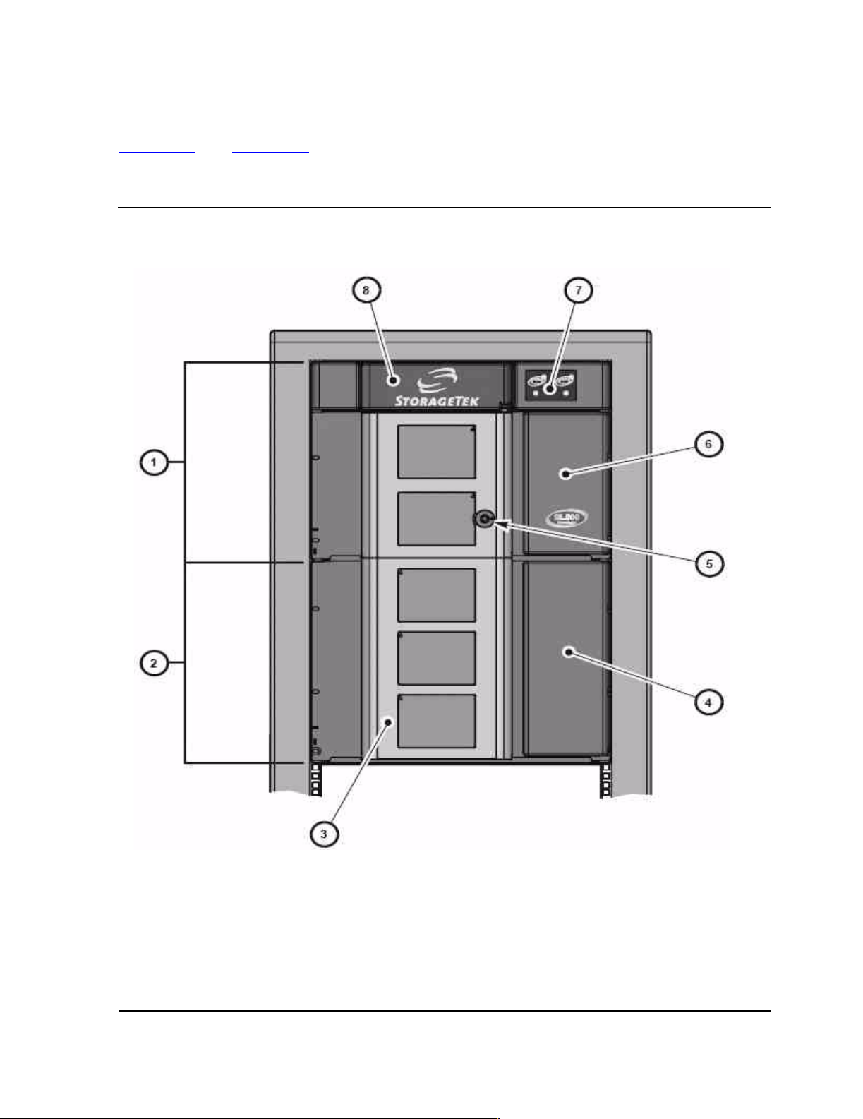
Figure 1-1 and Figure 1-2 show the tape library views and the locations of its
components.
Figur e 1-1. Front View of Tape Library Components
Views and Locations
1. Base module
2. Drive ex pansion modu le
3. Library door
4. Drive ex pansion modu le cartridge a ccess port (CAP)
5. Library door lock
6. Base unit cartridge access port (CAP)
7. Keypad assembly
8. Robo tics unit
SL500 (M852x) Tape Library Installation and User’s Gu id e—541531-006
1-2
Page 13
Overview of the Tape Library
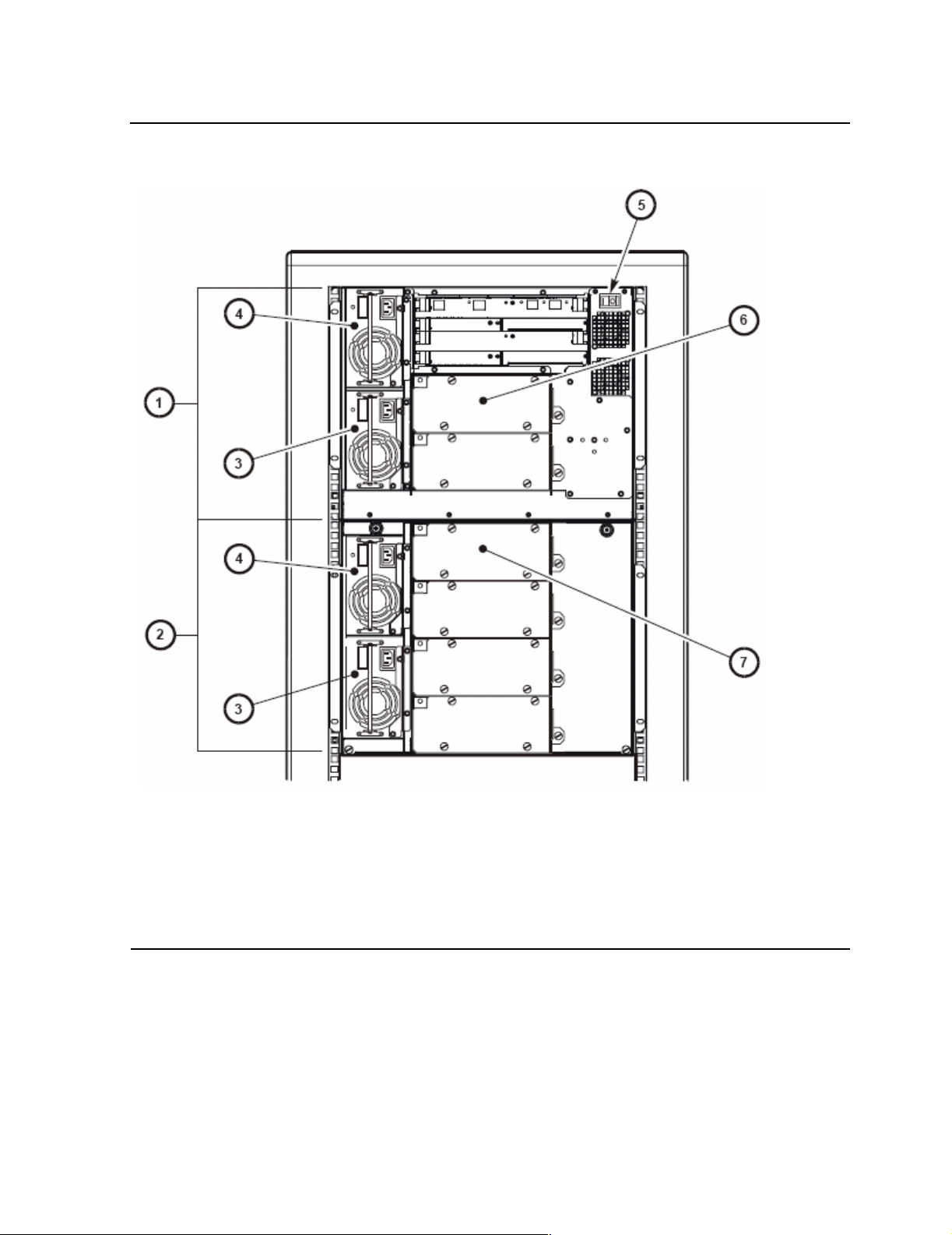
Figure 1-2. Back View of Tape Library Components
Views and Locations
1. Base module
2. Drive ex pans ion module
3. Redundant power supply
4. Standard power s upply
5. Library pow er switch
6. Tape drive 1 in b as e unit
7. Tape drive 1 in e xpa ns ion module
SL500 (M852x) Tape Library Installation and User’s Gu id e—541531-006
1-3
Page 14

Overview of the Tape Library
Physical Configurations
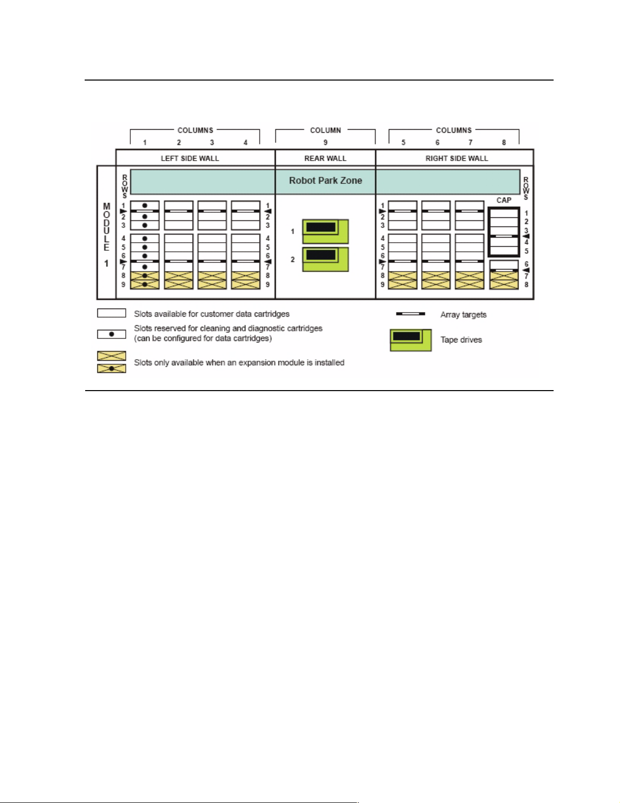
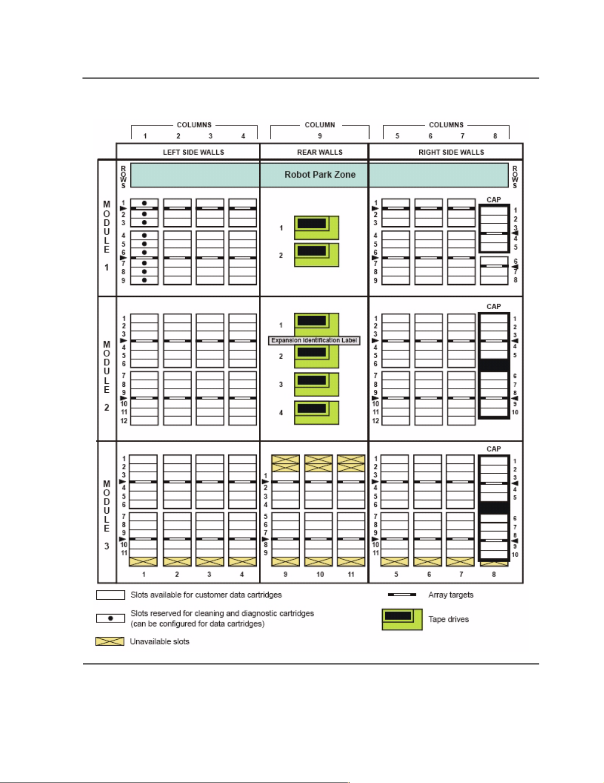
Figure 1-3 on page 1-5 shows a tape library with only a base module. Figure 1-4 on
page 1-6 shows a tape library with a base module that has nine reserved slots, one
drive expansion module, and one cartridge expansion module.
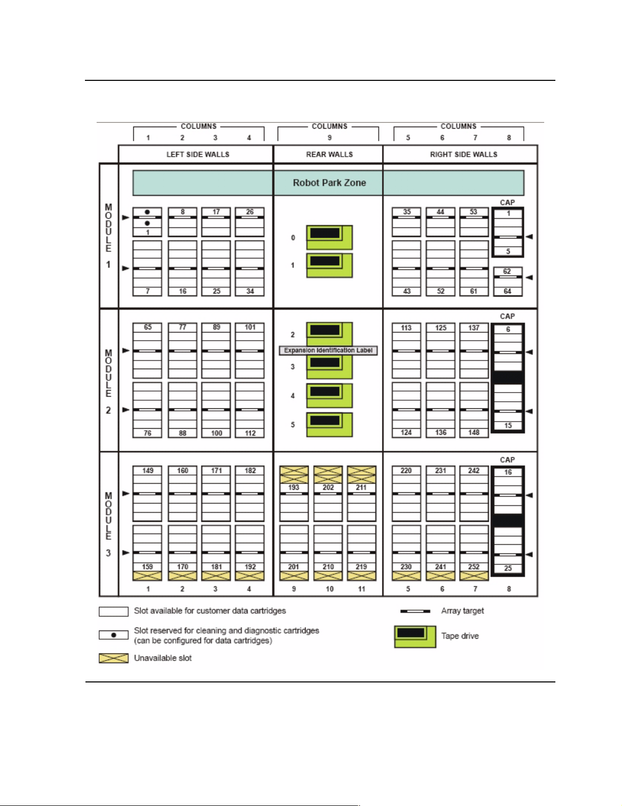
Figure 1-5 on page 1-7 shows a tape library with a base module that has two reserved
slots, one drive expansion module, and one cartridge expansion module.
Note. In Figure 1-5 on page 1-7, all s ix tap e drives are insta lled. When only s ome of the tape
drives are ins tal led, only those th at are powered-on receive SCSI address es , start ing with the
top-most tape d r ive.
The storage slot numbering begins with the first slot a fter t he reserved slots in column 1.
Figure 1-5
are config ured as storage slots, the top slot (row 1) would be 1. If the CAP in m odule 1 is
configured as storage slots, the top CAP slot (row 1) is 62 if there are two reserved slots as
shown, or 64 if no slots are re se rv ed.
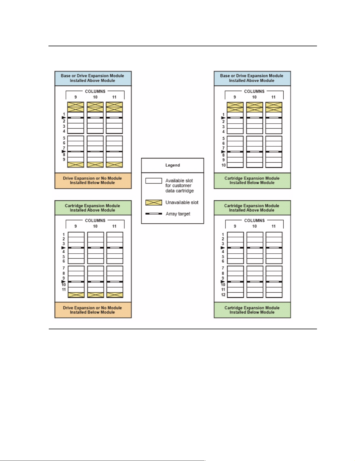
Figure 1-6 on page 1-8 shows the slot capacity of a cartridge expansion module
according to which type of module is installed above and below it.
on pag e1-7 shows t w o r es erved s lots, but ther e c ould be mo re. If t he reser v ed slot s
Physical Configurations
The numbering scheme uses the tape library, module, row and column scheme. Four
integers are used to represent the cartridge and tape drive slots, as viewed from the
front of the tape library.
1. Library number (always 0)
2. Library module number 1 (top of rack) through 5 (bottom of rack)
3. Row number 1 through 9 (base module) or 1 through 12 (expansion module)
4. Column number 1 through 9 for base module and drive expansion module, 1
through 11 for cartridge expansion module
SL500 (M852x) Tape Library Installation and User’s Gu id e—541531-006
1-4
Page 15
Overview of the Tape Library
Figure 1-3. Base Module Slots
Physical Configurations
SL500 (M852x) Tape Library Installation and User’s Gu id e—541531-006
1-5
Page 16
Overview of the Tape Library
Figure 1-4. Slots L ocations for Firmware Slot Mapping
Physical Configurations
SL500 (M852x) Tape Library Installation and User’s Gu id e—541531-006
1-6
Page 17
Overview of the Tape Library
Figure 1-5. Slots Locations for SCSI Element Numbering Mapping
Physical Configurations
SL500 (M852x) Tape Library Installation and User’s Gu id e—541531-006
1-7
Page 18
Overview of the Tape Library
Figure 1-6. Slot Capacity for Back Wall of Cartridge Expansion Module
Physical Configurations
SL500 (M852x) Tape Library Installation and User’s Gu id e—541531-006
1-8
Page 19

Overview of the Tape Library
Capacities
Table 1-1 on page 1-10 shows the number of cartridge and tape drive slots available
depending on the type and number of modules installed.
Slot counts are based on the following assumptions:
Capacity includes reserved slots for diagnostic and cleaning cartridges.
•
Reserved slots (for cleaning and dia gnostic cart ridges) are located only in the base
•
module on the left side as you open the front door. These slots can be configured
for data cartridges if desired.
The base module has a 5-slot CAP; the drive expansion module (DEM) and
•
cartridge expan sion modu l e (CEM) each have tw o 5-slot CA Ps. These slot s can be
configured for data cartridges if desired.
When DEMs and CEMs are installed in the same library, the DEMs are above all of
•
the CEMs.
When you add an expansion module below an existing module, you increase the
capacity of the module directly above it by:
Capacities
Base module: +16 slots
•
CEM (when another CEM is below it): +10 slots
•
CEM (when a DEM is below it): +7 slots
•
DEM: +7 slots
•
When a CEM is installed below a base module or DEM, the top two rows on columns
9, 10, and 11 of the CEM are not accessible (-6 slots because of the tape drives).
The lowest module in the rack requires installation of the floor. The floor limits the
distance the robot can travel, which makes the bottom row(s) in the lowest module
inaccessible:
Base module: -16 slots
•
DEM: -7 slots
•
CEM (below another CEM): -16 slots (-10 slots on the lowest CEM, -6 slots on the
•
CEM above it)
CEM (below base module or DEM): -16 slots
•
Cartridge access ports:
Base module: 5 slots (one magazine)
•
Each DEM: 10 slots (two magazines)
•
Each CEM 10 slots (two magazines)
•
SL500 (M852x) Tape Library Installation and User’s Gu id e—541531-006
1-9
Page 20

Overview of the Tape Library
Table 1-1. Cartridge Slot and Tape Drive Capacities
Capacities
Modules Maximum Number of Tape Drives CAP
Slots
Total
Numb er of
Slots
2 6 10 14 18
Base Module 30 5 35
20 cartridge upgrade key 50 5 55
Adding one expansion module
Base module plus 1
100 15 115
limited DEM
Base module plus 1
143 15 158
DEM
Base module plus 1
170 15 185
CEM
Adding two expansion modules
Base module plus 2
227 25 252
limited D E Ms
Base module plus 1
254 25 279
DEM, 1 CEM
Base module plus 2
290 25 315
CEMs
Adding three expansion modules
Base module plus 3
DEMs
Base module plus 2
DEMs, 1 CEM
Base module plus 1
DEM, 2 CEMs
Base module plus 3
410 35 445
CEMs
Adding four expansion modules
Base module plus 4
DEMs
Base module plus 3
DEMs, 1 CEM
Base module plus 2
DEMs, 2 CEMs
Base module plus 1
DEM, 3 CEMs
Base module plus 4
530 45 575
CEMs
311 35 346
338 35 373
374 35 409
395 45 440
422 45 467
458 45 503
494 45 539
SL500 (M852x) Tape Library Installation and User’s Gu id e—541531-006
1-10
Page 21

Overview of the Tape Library
Robotics Unit
The robotics unit provides movement of cartridges among the storage slots, tape
drives, and cartridge access ports (CAPs). The three main robotic components are:
Z drive assembly
•
X table assembly
•
Hand assembly
•
The Z drive assembly uses the Z drive pulley to move the X table up and down to the
desired slot or tape drive. At the same time, the X carriage assembly (containing the
hand) moves the hand forward and backward; the wrist motor rotates the hand right
and left.
The hand assembly contains the wrist hub assembly, gripper assembly, and bar-code
scanner. The gripper assembly has fingers that grasp the sides of the cartridge. If the
library loses power while a cartridge is between the fingers, the manual release screw
is used to remove the cartridge. A worm gear can be used to rotate the hand to the
correct position to access the manual release screw.
Robotics Unit
For safety purposes, the robotics will be parked in the robotics unit when the front door
is opened or when the Open Door button is pressed on the keypad. Parked means
that the robotics components are fully retracted into the robotics unit at the top of the
library. To verify the robot is parked, look at the lever in the cutout beneath the facade
and to the bottom left of the keypad, the lever should be to the left.
The robotics unit is accessible from the front of the rack.
SL500 (M852x) Tape Library Installation and User’s Gu id e—541531-006
1-11
Page 22
Overview of the Tape Library
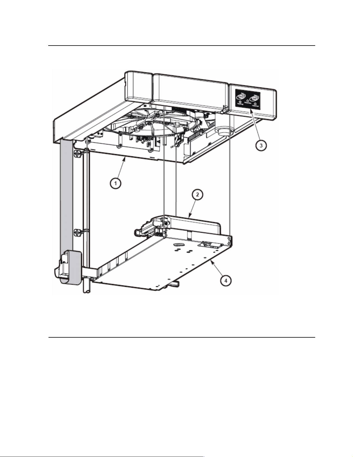
Figure 1-7. Robotics Components
Robotics Unit
1. Z dri v e as s embly
2. Hand ass embly
3. Keypad assembly
4. X table assembly
SL500 (M852x) Tape Library Installation and User’s Gu id e—541531-006
1-12
Page 23
Overview of the Tape Library
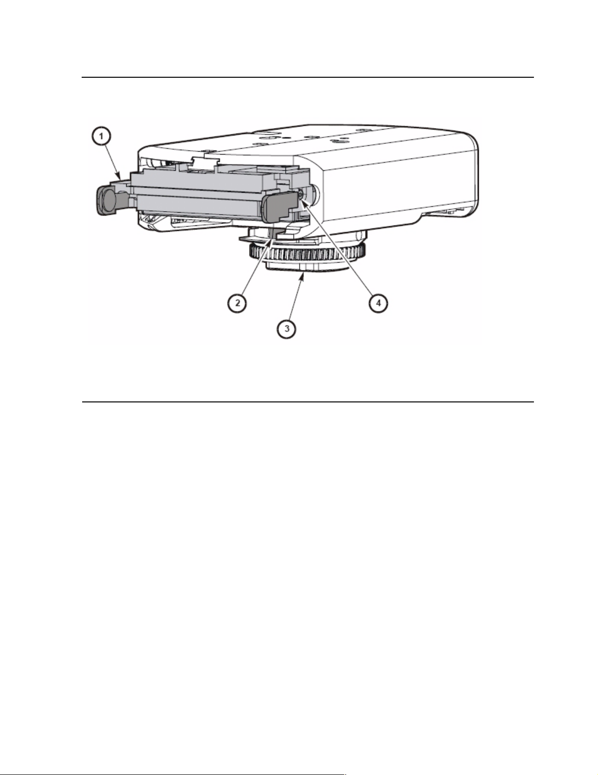
Figure 1-8. Hand Assembly
Robotics Unit
1. Gripper
2. Bar-code scanner
3. Wrist hub
4. Finger release screw
SL500 (M852x) Tape Library Installation and User’s Gu id e—541531-006
1-13
Page 24

Overview of the Tape Library
Electronics
The electronics consists of the control path and robotic cards in the base unit.
Communications include:
Command line interface (CLI) over an RS232 port
•
Public Ethernet port (The private port is for future use)
•
Point to point library/tape drive RS232 interface
•
Control path card for LVD SCSI or SCSI over Fibre Channel
•
Sensors include:
Card temperature
•
Fan operational
•
Power safe
•
Electronics
Tape drive present
•
Tape drive fault LED
•
RLC Card
The RLC card is the processor card. It contains all the necessary hardware to maintain
the robotics, interfaces, servo and vision control, and the door/CAP sensor status.
Interface Cards
The MPW card is the LVD SCSI interface card. The MPU2 card is the Fibre Channel
interface card.
Fans
The fans provide cooling for the library el ect ronics. Th e ta pe driv es and power supplie s
contain their own fans.
SL500 (M852x) Tape Library Installation and User’s Gu id e—541531-006
1-14
Page 25

Overview of the Tape Library
Power System
The base unit has one standard power supply. A second supply can be ordered and
installed to provide redundant power to the module components. Each supply should
be plugged into a separate circuit and powered on to provide redundant power. If one
supply fails, the second supply automatically provides power.
A single power switch on the back of the tape library is used to power on or power off
all the power supplies in the rack:
The ON position is 1.
•
The OFF position is 0.
•
Cartridge Access Port
The cartridge access port (CAP) can be used to add cartridges to the tape library, or
remove cartridges from the tape library without interrupting normal robotic operation.
The CAP in the base module has one five slot magazine; the CAP in the drive
expansion module has two five slot magazines.
Power System
Although the CAPs are not physically connect ed, they are logical ly conne cted. If any of
the CAPs are open, the CAP LED on the keypad will be on, alerting the operator to
take action to close the CAP. If all of the CAPs are closed, the CAP LED will be off.
You can use the keypad on the robotics unit to issue a command for the robot to
unlock the CAP.
The CAP has two settings, ALLOW and PREVENT. ALLOW is the default setting after
you power on or reset the tape library. The following table shows how these settings
affect the CAPs.
CAP Condition ALLOW PREVENT
All of the CAPs are
closed.
Any of the CAPs
are open.
When you press the CAP
button all of the CAPs in the
rack will open.
The librar y firmware turns on
the CAP LED.
When you press the CAP
button, any CAP that is not
open in the rack will open.
When you press the CAP
button, the action is ignored
and all the CAPs remain
closed.
When you press the CAP
button, the action is ignored
and all of the CAPs remain
in their individual current
state of open or closed.
SL500 (M852x) Tape Library Installation and User’s Gu id e—541531-006
1-15
Page 26

Overview of the Tape Library
Supported Tape Drives
The tape library can accommodate from 1 to 14 tape drives. The LTO generation 3
tape drives supports Ultrium 3 media, Ultrium 2 media, and Ultrium 1 media (read
only).
Figure 1-9. Supported Tape Drives
Product Number Description
N1523A LTO Gen er ation 3 tape dri v e w ith SCSI I nterfac e for NonStop S-series
servers
M8504 LTO Gene ration 3 tape drive with a Fibre C hannel interfac e f or
Integrity NonStop NS-series servers
LTO Ultrium
Linear-Tape Open (LTO) is a set of tape data format standards created to enable data
interchange among different LTO Ultrium tape drive vendors. These LTO Ultrium
standards allow data cartridges to be shared.
Supported Tape Drives
Table 1-2. LTO Generation 3 Specifications
Specification Performance
Capacity, native (unco m pressed) 400 gigab y te s
Capacity (compressed) 800 gigabytes
Data transfer rate, native (uncompress ed) 80 mega by t es per second
SL500 (M852x) Tape Library Installation and User’s Gu id e—541531-006
1-16
Page 27

Overview of the Tape Library
Audit of Tape Library
An audit is the method by which the tape library keeps track of all cartridge locations
within the unit. An audit occurs when you:
Power on the library
•
Open and close the front door
•
Close the CAP (CAP slots only)
•
Initialization occurs when the tape library is powered on or when the front door is
opened and closed. During initialization, the RLC card applies voltage to the motors
(gripper, reach, wrist, and Z drive). The robotic components ranges of motion are
tested, the targets and labels are read for calibration purposes, and the slots are
audited for cartridge VOLIDs. This information is stored on the RLC card.
Note.
When an audit occurs, the tapes in the tape drives are not audited.
•
Audit of Tape Library
If you manually exchange a cartridge from a tape drive for one in storage, you must update
•
the tape management database or an e rror will occur.
The bar code scanner on the hand assembly reads the labels on the cartridges.
Safety Features
The following subsections describe the safety features that are incorporated into the
tape library.
Cards and Power Supply
The RLC card or SCSI (MPW) interface card, and the power supply are housed inside
protective modules to prevent you from coming into contact with hazardous voltages
and sensitive electronics.
Robotics
The software parks the robot by retracting it into the robotics unit module before the
front door can be opened to prevent the robot from being damaged.
When the front door is opened, power is removed from the robot.
Front Door
The front door must be opened with a key to ensure that the data is secure. If the door
is not fully closed, a sensor relays the condition to the software and the robot remains
disabled.
SL500 (M852x) Tape Library Installation and User’s Gu id e—541531-006
1-17
Page 28

Overview of the Tape Library
Interfaces
The major tape library interfaces are:
Library control path support for LVD SCSI
•
Public 100BaseT ethernet port
•
CLI serial port for local access for service representative, manufacturing and
•
engineering (Not for customer use).
Environmental port for monitoring fans, tape drives, and power. This port is internal
•
and cannot be accessed by the customer.
Cartridge access ports and sensors for indicating a door open or closed condition.
•
Front door opened button (on keypad), key for opening door, sensor LED that
•
indicates door is closed and latched.
Figure 1-10. Tape Library Interfaces Locations
Interfaces
1. Private Ethernet port is for future use.
2. Eject OK (hot-swappable) LED, when on, indicat es th at th e R LC card can be removed.
3. Public E th ernet port is for r em ote service ac ce s s .
4. Fault LED indicates tha t th e c ontroller has det ec t ed a problem.
5. Reserved for future use.
6. Standby LED, wh en lit , indicates the RL C c ard (when two R LC c ards are installed) is in
standby mode (future feature).
7. CLI port is an RJ-45 serial port for service represen tativ es .
8. Active LE D , w hen lit, indicate s th is R LC c ard is active if two R LC cards are in s talle d. If
only one card is installed, the LED is always on (f ut ure feature) .
Each installed tape drive contains the following interfaces:
• Tape Transport Interface (TTI) receives commands form the RLC card.
Some exa m ples of signals th at are transferred over the TT I are “ready,”
“unloading,” “busy,” and “sense” information.
• The data path ca n have a single -port SCSI.
SL500 (M852x) Tape Library Installation and User’s Gu id e—541531-006
1-18
Page 29

2 Control s and Indicators
This section includes:
Power Switch 2-1
Keypad 2-1
Power Switch
When the switch is in position 1 the tape library and tape dri ves are power ed on. When
the switch is in position 0 the tape library and tape drives are powered off.
Note. Earlier built tap e libraries had power supp lies t hat had individ ual power switc hes. Later
tape libraries have one pow er switch that co nt rols all power supplies in the rac k .
Keypad
The keypad is used to open the door, open the CAP, and notify the user if service is
required.
1. The Door Open button opens the tape library door. All doors function as one door
and can not be opened individually.
2. The CAP Open button opens all CAP doors.
3. The Library Active LED, if on, indicates the tape library is functioning properly. If
the Library Active LED is flashing, call your service representative.
4. If the Service Robot LED is on and flashing, call your service representative.
5. If the Service Required LED is on and flashing, call your service representative.
SL500 (M852x) Tape Library Installation and User’s Gu id e—541531-006
2-1
Page 30

Controls and Indicators
Figure 2-1. Buttons and Indicators
Keypad
1. Door Open button 5. Service Required LED
2. Door Open LED 6. Library Active LED
3. CAP Open button 7. Service Robot LED
4. CAP Op en LED
SL500 (M852x) Tape Library Installation and User’s Gu id e—541531-006
2-2
Page 31

Controls and Indicators
Table 2-1. Keypad Buttons and Indicators
Buttons/Indicators Description
Service Robot Indicator
Libr ary Active Indicator
Service Required Indicator
LED is lit w hen the robot is not functioning. Replace
the robotics unit.
LED is normally solid gr een.
•
LED turns off w hen the tape libr ary ex periences
•
a failure. If it ne v er t urns on, an initialization or
power fai lure has occurred.
LED is normally solid gr een.
•
LED is lit when the tape library experiences a
•
non-robotic failure.
Keypad
Open Door Indicator
LED flashes amber when the Open Door button
•
is pressed.
LED is solid amber whe n t he robot is parked in
•
the roboti c s u nit .
LED flashes during init ialization and audit.
•
LED is not lit w hen the library is re ady for
•
customer use.
Button
When pressed:
1. Software allows the current job to complete. This
could take aw hile.
2. Software retracts the robot into the robotics unit
so that it will not be damag ed when you open
the door with the key.
Open CAP Indicator
LED is amber when any CAP doors are open
•
LED is not lit w hen all CAP doors are shut
•
LED fl as hes durin g audit
•
Button
Button is used to tell the robot to open the CAP
doors.
SL500 (M852x) Tape Library Installation and User’s Gu id e—541531-006
2-3
Page 32

Controls and Indicators
Keypad
SL500 (M852x) Tape Library Installation and User’s Gu id e—541531-006
2-4
Page 33

3 Library Operation
This section includes:
Automated Mode
Manual Mode 3-4
Automated Mode
Automated mode is the normal operating mode of the tape library. The controlling
software instruct s the hand assembly to move cartridges among the stora ge sl ot s, tape
drives, and cartridge access port (CAP) without operator intervention.
Opening the Front Door (With Power)
To open the front door when tape library power exists:
1. Press the Open Door button on the keypad.
a. The software allows the current job to complete.
b. The software retracts the robot into the robotic unit to prevent the robot from
being damaged and to prepare it for servicing.
2. When the Open Door indicator turns on, use the key to open the door.
3-1
Securing the Front Door (With Power)
To secure the front door when tape library power exists, push it closed and use the key
to lock it.
Entering a Cartridge Through the CAP
The base module CAP contains a standard five slot magazine. The expansion module
CAP has two five slot magazines. The CAPs allow you to insert cartridges and remove
cartridges from the tape library.
To enter a cartridge into the CAP:
1. Be sure that the CAP Prevent/Allow state is set to Allow.
2. Press the CAP Open button on the keypad.
The robot opens the CAP door and the CAP Open LED is turned on.
3. Grip the handle of the magazine and slide it out of the CAP and onto the door.
Note. Do not rem ov e the magazine from the door. Leaving the mag az ine on the door rails
will allow th e m agazine to slide easier into th e C AP.
SL500 (M852x) Tape Library Installation and User’s Gu id e—541531-006
3-1
Page 34

Library Operation
4. Place the cartridge into one of the magazine slots, making sure that the VOLID
label is visible and the hub of the cartridge is down.
5. Grip the handle and slide the magazine back into the CAP.
Figure 3-1. S liding a Magazine Into a CAP
Entering a Cartridge Through the CAP
6. Close the CAP door making sure that the door is securely latched.
SL500 (M852x) Tape Library Installation and User’s Gu id e—541531-006
3-2
Page 35

Library Operation
Powering On t he Tape Library
To power on the librar y:
1. Close and lock the front door if the door is open.
2. Press the power switch (on the top right corner of the back of the library) to the ON
(1) position.
Powering Off the Tape Library
Caution. If you power off th e ta pe library without performing the following procedure, you risk
possible equipment or ca rt ridge damage or loss of data.
1. Make sure that all jobs have completed processing.
2. Make sure the tape library and tape drives are not in use.
3. Move the power on/off switch to the OFF position (0).
Powering On the Tape Library
SL500 (M852x) Tape Library Installation and User’s Gu id e—541531-006
3-3
Page 36

Library Operation
Manual Mode
This section describes the operation of the tape library in manual mode. Manual mode
occurs then the tape library is taken offline, or loses power, or the front door is opened.
Opening the Front Door (Without Power)
To open the front door when no tape library power exists:
Note. You must manually move the robotics park lever (beneat h the facade and to the bott om
left of the keypa d) t o t he left position so t hat you can ope n th e door with the k ey. Under nor m al
conditio ns , the lev er signifies th at th e robot is parked in si de the robotics unit at the top of th e
tape library, and the door can be safely opened. When no power exists, the robot is not actually
parked, but you will be able to open the door when you move the lever to the left.
Figure 3-2. Lever Not in Parked Position
Manual Mode
1. Press the power switch on the back of the tape library to the OFF position.
2. Remove the robotic facade from the top of the library by gently pulling the facade
from side to side to pull the ball studs away from the clips. You might have to use a
screwdriver to gently pry it off.
SL500 (M852x) Tape Library Installation and User’s Gu id e—541531-006
3-4
Page 37

Library Operation
WARNING. Possible injury to finger: Make sure that your finger is completely to the left in the
next step so that it will not be pinched when the door locking lever extends as shown in the
lower picture.
Figure 3-3. Door Locking Lever Extended
Securing the Front Door (Without Power)
3. While using one hand to move the robotics park lever to the left, use your other
hand to unlock the door with the key.
Securing the Front Door (Without Power)
To secure the front door when no tape library power exists:
1. Remove the robotic facade from the top of the tape library by gently pulling the
facade from side to side to pull the ball studs away from the clips. You might have
to use a screwdriver to gently pry it off.
Caution. Possible component damage: Note the door locking lever protruding from the top of
the door. Do not let it hi t the robotics park lev er when you close the door.
2. While using one hand to move the robotics park lever to the left, use your other
hand to close the door.
SL500 (M852x) Tape Library Installation and User’s Gu id e—541531-006
3-5
Page 38

Library Operation
Figure 3-4. Moving Robotics Park Lever
3. While still holding the door shut, release the robotics park lever.
Locate and Remove Cartridge
4. Use the key to lock the door. The robotics lever automatically moves to the right
when the door locking lever retracts.
Locate and Remove Cartridge
To locate a particular cartridge inside the tape library:
1. Open the door .
2. Locate the particular cartridge by its VOLID (volume ID) label and slot.
3. Remove the cartridge from the slot by sliding the cartridge out.
4. Close the tape library door.
Insert Cartridges Into Slots
Depending on the version and configuration of your tape library, some storage slots
cannot be used.
Note. You do not have to insert a cartridge into every storage slot. The tape library
automatic ally audits cartridges and empty slots as part of its in iti aliz ation routin e.
Caution. Inserting the cartridges correctly is critical for library operation. If you do not orient
the cartridges correct ly or do not insert th em all the way into th e s t orage slots, the tap e library
might fail. Make sure you insert the cartridges into the magazine.
1. Check the cartridges to make sure they are correctly labeled.
2. Insert as many cartridges into the tape library as you want and as your
configuration allows, making sure you seat them all the way into the storage slots.
SL500 (M852x) Tape Library Installation and User’s Gu id e—541531-006
3-6
Page 39

Library Operation
Figure 3-5. Inserting Cartridges Into Slots
Insert Cartridges Into Slots
1. Wall of arrays slots
2. Cartridge
SL500 (M852x) Tape Library Installation and User’s Gu id e—541531-006
3-7
Page 40

Library Operation
Inserting a Cartridge Into a Tap e Drive
To manually insert a cartridge into a tape drive:
1. Obtain the VOLID label, location, and tape drive number from the server console.
2. Open the door .
3. Locate the cartridge.
Caution. Potential equipment d am age. You must ins ert the cartri dge properly or y ou will
damage the tape drive.
4. Hold the cartridge so that the VOLID is facing you and can be read from right to
left.
5. Insert the cartridge into the tape drive.
6. Close the tape library access door.
Inserting a Cartridge Into a Tape Drive
Figure 3-6. Inserting Cart rid ge I nto Tap e Dr ive
1. Cartridge
2. Drive
SL500 (M852x) Tape Library Installation and User’s Gu id e—541531-006
3-8
Page 41

Library Operation
Removing a Cartridge From a Tap e Drive
To manually remove a cartridge from a tape drive:
1. Open the door and locate the appropriate tape drive.
Caution. Possible data los s . Fa ilure to perfor m and wait appro x im at ely 12 seconds until the
operation completes.
2. Press the Unload button on the tape drive and wait approximately 12 seconds until
the operation completes.
Figure 3-7. Location of Unload Button
Removing a Cartridge From a Tape Drive
3. Gently pull the cartridge from the tape drive.
4. Store the cartridge in an empty slot or outside the tape library.
Note. If you store the cartridge in an empty slot, you must reinitialize the tape library.
5. Close the tape library door.
SL500 (M852x) Tape Library Installation and User’s Gu id e—541531-006
3-9
Page 42

Library Operation
Removing a Cartridge From the Gripper Assembly
Removing a Cartridge From the Gripper Assembly
The hand assembly can be in any position when the tape library loses power. Before
you can remove the cartridge, the hand assembly must be facing the front left arrays
and aligned with an empty slot.
If the hand assembly is facing right:
1. Gently turn the hand to the left.
2. Slide the hand assembly along the rail until the gripper is positioned across from
an empty slot and close to you.
3. Continue with the following steps.
If the hand assembly is facing left:
1. Turn the gripper belt to extend the gripper until the release screw is accessible.
2. Use a small, flat blade screwdriver to turn the screw 1/4 turn clockwise until the
cartridge is released.
3. Push the cartridge into a slot.
4. Gently push the gripper back into the hand.
5. Slide the hand assembly toward the back of the tape library.
6. Remove the cartridge from the slot, or leave it there.
SL500 (M852x) Tape Library Installation and User’s Gu id e—541531-006
3-10
Page 43

Library Operation
Figure 3-8. Manual Release Screw
Replacing a Cleaning Cartridge
1. Gripper belt and pulley s
2. Gripper
3. Release screw
Replacing a Cleaning Cartridge
Cleaning cartridges have a limited life span. When the usage count exceeds its limit,
you must replace it with a new one.
To replace a cleaning cartridge:
1. Open the door .
2. Remove the expired cleaning cartridge from its reserved slot.
3. Insert the new cleaning cartridge into that slot.
4. Close the tape library door.
5. Wait until the initialization tests complete before performing another task.
SL500 (M852x) Tape Library Installation and User’s Gu id e—541531-006
3-11
Page 44

Library Operation
Replacing a Cleaning Cartridge
SL500 (M852x) Tape Library Installation and User’s Gu id e—541531-006
3-12
Page 45

4 Cartri dge Info rm a tio n
This section includes:
Handle Cartridges 4-1
Inspect Cartridges 4-1
Maintain Cartridges 4-2
Ultrium Cartridges 4-3
Handle Cartridges
Improper handling of cartridges can result in loss of data or damage to a tape library
component.
To handle a cartridge correctly:
Make sure the leader is latched every time you pick up a cartridge.
•
Keep cartridges clean.
•
Inspect a cartridge be fore e ach use, a nd neve r put a d amag ed cartridge into a tape
•
drive or tape library.
Never pull tape from a cartridge.
•
Never open a cartridge.
•
Do not handle tape that is outside the cartridge; the tape edge might be damaged.
•
Do not expose the tape or cartridge to direct sunlight or moisture.
•
Do not expose a recorded cartridge to magnetic fields; this might destroy data on
•
the tape.
Inspect Cartridges
A defective or dirty cartridge can damage a tape drive. Always inspect a cartridge
before you insert it into a tape drive or a tape library. Look for:
Cracked or broken cartridge
•
Broken leader
•
Broken leader latch
•
Damaged write-protect switch
•
Liquid in the cartridge
•
Labels not firmly or neatly attached or extending over the cartridge edge
•
Any other obvious damage
•
SL500 (M852x) Tape Library Installation and User’s Gu id e—541531-006
4-1
Page 46

Cartridge Information
Maintain Cartridges
It is important to keep your tape cartridges in good condition. A defective or dirty
cartridge can damage a tape drive.
When you store a cartridge:
Leave it in its protective wrapping until you are ready to use it.
•
Choose a clean environment that duplicates the conditions of the room in which it
•
is used.
Make sure the cartridge has been in its operating environment for at least 24
•
hours.
When you clean a cartridge exterior:
Caution. Do not use certain solvents to remove labels or to clean cartridges because they can
damage th e c art ridges. Do not use ac etone, trichl oroethane, tolu ene, xylene, ben z ene, ketone,
methylet hy l k et one, methy lene chloride, et hy ldichloride, es t ers , et hy l ac etate, or similar
chemicals.
Maintain Cartridges
Wipe all dust, dirt, and moisture from the cartridge with a lint free cloth.
•
Use cleaning wipes that are saturated with isopropyl alcohol. Do not let any
•
solution touch the tape or get inside the cartridge.
SL500 (M852x) Tape Library Installation and User’s Gu id e—541531-006
4-2
Page 47

Cartridge Information
Ultrium Cartridges
Figure 4-1. Ultrium Cartridge Components
Ultrium Cartridges
1. Write-protect switch (data cartridge has red switch, cleaning cartridge has gray switch)
2. Volume ID labe l (barcode to hu b s ide of cartridge)
3. Access door
4. Leader pin
Apply Cartridge La be ls
Cartridge labels reflect the cartridge media and usage. If your cartridges were not
ordered with labels already applied, you must apply them yourself. You must correctly
label all cartridges for tape library use.
Caution. Possible misread of volu m e number label: Make sure th e edges of the labels do not
curl. Curling causes th e c art ridges to stick in t he tape drive loa der and the robot t o m is read the
label.
Valid Labels
LTO cartridge labels have eight characters. The last two characters are the Media ID
(C1, C2, CU, L1, L2, or L3). CLN or DG are the first characters on the cleaning or
diagnostic label.
SL500 (M852x) Tape Library Installation and User’s Gu id e—541531-006
4-3
Page 48

Cartridge Information
Table 4-1. LTO Cartridge Codes
Label Type of Cartridge
CLN plus C1 Cleaning cartridge for tape drives
CLN plus C U Univer sa l c leaning cartr idge
DG plus L Diagnos t ic c art ridge (Apply a D G label to a blan k d ata
L1 Generation 1 data cartridge
L2 G eneration 2 data cartridge
L3 Generation 3 data cartridge
Figure 4-2. LTO Cartridge Labels
Val id Labels
cartridg e t o be used for dia gnostic tests.)
When an audit occurs the tapes in the tape drives are not audited. Unlabeled
cartridges are not supported and will not be recognized by an audit.
SL500 (M852x) Tape Library Installation and User’s Gu id e—541531-006
4-4
Page 49

Cartridge Information
Perform these steps before applying the label into the recessed area on the cartridge:
1. Make sure the cartridge has been at room temperature for at least 24 hours.
2. Clean the surface where the labels will be placed using a cleaning solution made
for this purpose.
3. Locate the type of label that you require.
4. Hold the cartridge so that the write-protect switch is toward you.
5. Attach the label to the cartridge as shown in Figure 4-3.
Figure 4-3. Ultrium Cartridge Label
Val id Labels
1. Volume number label
SL500 (M852x) Tape Library Installation and User’s Gu id e—541531-006
4-5
Page 50

Cartridge Information
Setting the Write-Protect Switch
You can set the write-protect switch so the cartridge is write enabled. To write-enable
the tapes, slide the switch to reveal the open lock symbol . In this position, the tape
drive can write as will as read data. This setting is recommended when inserting
cartridges into the tape library.
You can set the write-protect switch so that the cartridge is read only. Slide the switch
to reveal the symbol of a closed lock. In this position, the tape drive can only read data
from the tape but cannot write data to it.
Figure 4-4. Write-Protect Switch
Setting the Write-Protect Switch
1. Write-protect switch (D ata cartridge has red switch. C leaning cartr idge has gray swit c h. )
2. Write-enabled
3. Write-protected
SL500 (M852x) Tape Library Installation and User’s Gu id e—541531-006
4-6
Page 51

Cartridge Information
Table 4-2. LTO Gen 1, Gen 2, and Gen 3 Cartridge Specifications
Specification L3 Cartridge L2 Cartridge L1 Cartridge
Setting the Write-Protect Switch
Capacity, native
400 GB 200 GB 100 GB
(uncompressed)
Capacity
800 GB 400 GB 200 GB
(compressed)
Read and w rit e
5.9 m/s 5.9 m/s 4.0 m/s
tape speed
Sear ch and r ewin d
7.0 m/s 7.0 m/s 7.0 m/s
speed
Archival life 15–30 years 15-30 years 15-30 years
Numbe r of tracks 704 tr ac k s 51 2 t racks 384 tracks
Dimensions
Width
Height
Depth
Weight
107 mm (4.2 in.)
22.9 mm (0.9 in.)
102 mm (4.0 in.)
210.0 g (0.46 lb)
107 mm (4.2 in.)
22.9 mm (0.9 in.)
102 mm (4.0 in.)
210.0 g (0.46 lb)
107 mm (4 .2 in. )
22.9 mm (0.9 in.)
102 mm (4 .0 in. )
210.0 g (0.46 lb)
Temperature
(noncondensing)
Operating
10 to 40°C (50 to
104°F)
10 to 40°C (50 to
104°F)
10 to 40°C (50 to
104°F)
Shipping
Wet bulb
-23 to 49°C (-10 to
120°F)
26°C (7 8°F)
-23 to 49°C (-10 to
120°F)
26°C (78°F)
-23 to 49°C (-10 to
120°F)
26°C (78°F)
Humidity 20–80% 20-80% 20-80%
SL500 (M852x) Tape Library Installation and User’s Gu id e—541531-006
4-7
Page 52

Cartridge Information
Setting the Write-Protect Switch
SL500 (M852x) Tape Library Installation and User’s Gu id e—541531-006
4-8
Page 53

5
Configuring the M8520 Tape Library
for the NonStop S-Series Server
The section covers:
Supported Connections 5-1
Adding the Control Path and the Data Path 5-1
Supported Connections
You can attach the M8520 tape library (control path and data path) to a NonStop
S-series server using one of the following:
ServerNet/DA
•
IOMF CRU
•
PMF CRU
•
Note. The control path is used to control the robot and the data path is used to control the tape
drive or driv es .
Adding the Control Path and the Data Path
ServerNet/DA
To add the control path to the server configuration database, use the SCF ADD SCSI
command. Use the SCF ADD TAPE command to add the data path. Before issuing
these commands, check that the tape drive(s) and tape library are installed properly.
To add the control path:
-> SCF
-> ADD SCSI $M8520, SENDTO STORAGE, PRIMARYLOCATION
(1,1,51), PRIMARYSAC 1, SCSIID 5, PRIMARYCPU 0, BACKUPCPU 1
-> START SCSI $M8520
-> STATUS SCSI $M8520, DETAIL
SL500 (M852x) Tape Library Installation and User’s Gu id e—541531-006
5-1
Page 54

Configuring the M8520 Tape Library for the NonStop
S-Series Server
To add the data path:
-> SCF
-> ADD TAPE $N1523A, SENDTO STORAGE, LOCATION (1,1,55), SAC
1, DEVICEID 5, PRIMARYCPU 0, BACKUPCPU 1
-> START TAPE $N1523A
-> STATUS TAPE $N1523A, DETAIL
For complete details about the ADD and STATUS commands, including command
syntax, see the SCF Reference Manual for the Storage Subsystem.
ServerNet/DA
SL500 (M852x) Tape Library Installation and User’s Gu id e—541531-006
5-2
Page 55

Configuring the M8520 Tape Library for the NonStop
S-Series Server
PMF CRU
To add the control path to the server configuration database, use the SCF ADD SCSI
command. Use the SCF ADD TAPE command to add the data path. Before issuing
these commands, check that the tape drive or drives and the tape library are installed
properly.
To add the control path:
-> SCF
-> ADD SCSI $M8520, SENDTO STORAGE, PRIMARYLOCATION
(1,1,50), SCSIID 5, PRIMARYCPU 0, BACKUPCPU 1
-> START SCSI $M8520
-> INFO SCSI $M8520, DETAIL
To add the data path:
-> SCF
-> ADD TAPE $N1523A, SENDTO STORAGE, LOCATION (1,1,55),
DEVICEID 5, PRIMARYCPU 0, BACKUPCPU 1
PMF CRU
-> START TAPE $N1523A
-> STATUS TAPE $N1523A, DETAIL
For more information on the ADD and STATUS commands, see the SCF Reference
Manual for the Storage Subsystem.
SL500 (M852x) Tape Library Installation and User’s Gu id e—541531-006
5-3
Page 56

Configuring the M8520 Tape Library for the NonStop
S-Series Server
PMF CRU
SL500 (M852x) Tape Library Installation and User’s Gu id e—541531-006
5-4
Page 57

6
Configuring the M8521 Tape Library
for the Integrity NonStop NS-Series
Server
The section covers:
Supported Connection 6-1
Adding the Control Path and Data Path 6-1
Supported Connection
You can attach the M8521 tape library (control path and data path) to a Fibre Channel
ServerNet adapter (FCSA) on an Integrity NonStop NS-series server.
Note. The contro l pat h is used to contro l th e robot, and the data path is used to co nt rol the
tape drive or driv es .
Adding the Control Path and Data Path
Note. To obtain the portname numbers for your control path and data path, contact a service
representative from STK. The portname numbers used in this section are examples only.
To add the control path, issue this SCF command:
SCF> ADD SCSI $device, SENDTO STORAGE, PRIMARYLOCATION
(group, module, slot), PRIMARYSAC sac-id, LUN lun-id,
PRIMARYPORT 64-bit-portname
Example:
SCF> ADD SCSI $M8521, SENDTO STORAGE, PRIMARYLOCATION
(110,2,2), PRIMARYSAC 2, LUN 0, PRIMARYPORT 1234567891234567
SL500 (M852x) Tape Library Installation and User’s Gu id e—541531-006
6-1
Page 58

Configuring the M8521 Tape Library for the Integrity
NonStop NS-Series Server
To add the data path:
Note. WWN (portname) for ea ch port is labeled on the back of each tape driv e.
1. In SCF, issue this command:
SCF> ADD TAPE $tape, SENDTO STORAGE, LOCATION (group, module,
slot), SAC sac-id, PORTNAME 64-bit-portname, LUN lun-id
Example:
SCF> ADD TAPE $M8504, SENDTO STORAGE, LOCATION (110,2,2), SAC
2, LUN 0, PORT 50060B00002E69CD
Note. The LUN ( logical unit num ber) for all Fibre C hannel tape storage devices d irectly
attached t o t he N onStop NS-series se rv er is 0.
2. To start the tape drive on the server, issue this command in SCF:
SCF> START TAPE $tape
Example:
Adding the Control Path and Data Path
SCF> START TAPE $M8504
For complete details about the ADD and STATUS commands, including command
syntax, see the SCF Reference Manual for the Storage Subsystem.
SL500 (M852x) Tape Library Installation and User’s Gu id e—541531-006
6-2
Page 59

7
Configuring the M8521 Tape Library
for the NonStop S-Series Server
The section covers:
Configuration Overview 7-1
Adding the Control Path and Data Path 7-3
Configuration Overview
You can attach the tape library (control path and data path) to a NonStop S-series
server via an IOAM enclosure. The tape library attaches to the FCSA (Fibre Channel
ServerNet adapter) in the IOAM enclosure. The ServerNet switch board on the IOAM
enclosure connects to a MSEB (Modular ServerNet Expansion Board) on a NonStop Sseries server via a fiber-optic cable. Figure 7-1 on page 7-2 shows a configuration
example of the tape library connected to a NonStop S-series server via an IOAM
enclosure.
SL500 (M852x) Tape Library Installation and User’s Gu id e—541531-006
7-1
Page 60

Configuring the M8521 Tape Library for the NonStop
S-Series Server
Figure 7-1. Configuration Example
Fiber-optic
Cable
IOAM
Enclosure
MSEBs
Configuration Overview
ServerNet
Switch Board
Fibre Channel
ServerNet
Adapters (FCSAs)
Control
Path
Data
Path
Fiber-optic
Cables
NonStop Modular Rack Tape Library
S-Series (Rear View)
System
Note. The contro l pat h is used to contro l th e robot, and the data path is used to co nt rol the
tape drive (M8504).
For more information on the IOAM enclosure, see the Modular I/O Installation and
Configuration Guide.
SL500 (M852x) Tape Library Installation and User’s Gu id e—541531-006
7-2
Page 61

Configuring the M8521 Tape Library for the NonStop
S-Series Server
Adding the Control Path and Data Path
Adding the Control Path and Data Path
Note. To obtain the portname numbers for your control path and data path, contact a service
representative from STK. The portname numbers used in this section are examples only.
To add the control path, issue this SCF command:
SCF> ADD SCSI $device, SENDTO STORAGE, PRIMARYLOCATION
(group, module, slot), PRIMARYSAC sac-id, LUN lun-id,
PRIMARYPORT 64-bit-portname
Example:
SCF> ADD SCSI $M8521, SENDTO STORAGE, PRIMARYLOCATION
(110,2,2), PRIMARYSAC 2, LUN 0, PRIMARYPORT 1234567891234567
To add the data path:
Note. WWN (portname) for ea ch port is labeled on the back of each tape driv e.
1. In SCF, issue this command:
SCF> ADD TAPE $tape, SENDTO STORAGE, LOCATION (group, module,
slot), SAC sac-id, PORTNAME 64-bit-portname, LUN lun-id
Example:
SCF> ADD TAPE $M8504, SENDTO STORAGE, LOCATION (110,2,2), SAC
2, LUN 0, PORT 50060B00002E69CD
Note. The LUN ( logical unit num ber) for all Fibre C hannel tape storage devices d irectly
attached to the IOAM enclosure is 0.
2. To start the tape drive on the server, issue this command in SCF:
SCF> START TAPE $tape
Example:
SCF> START TAPE $M8504
For complete details about the ADD and STATUS commands, including command
syntax, see the SCF Reference Manual for the Storage Subsystem.
SL500 (M852x) Tape Library Installation and User’s Gu id e—541531-006
7-3
Page 62

Configuring the M8521 Tape Library for the NonStop
S-Series Server
Adding the Control Path and Data Path
SL500 (M852x) Tape Library Installation and User’s Gu id e—541531-006
7-4
Page 63
A Specifications
The next pages provide tape library, tape drive, and cartridge specifications.
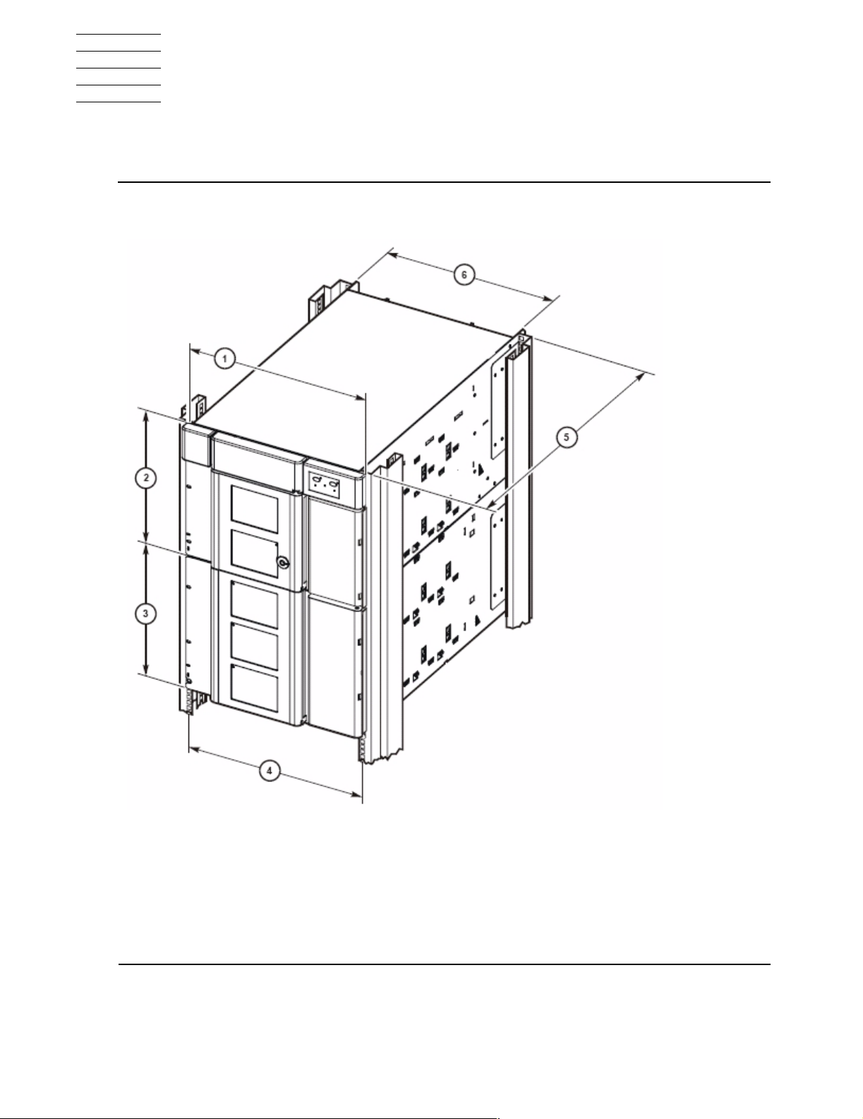
Figure A-1. Library and Rack Dimensions
1. 48.3 cm (19.0 in.) width of front of base module with flange
2. 35.6 cm (14.0 in.) height of base module
3. 35.6 cm (14.0 in.) heig ht of ex pans ion module
4. 46.5 cm (18.3 in.) distance between rack holes
5. 60.9 cm (24.0 in.) to 86.4 cm (34.0 in.), optimally 74 cm (29 in.) front to
rear rack mounting distance
6. 44.5 cm (17.5 in.) width of back of base module
SL500 (M852x) Tape Library Installation and User’s Gu id e—541531-006
A-1
Page 64

Specifications
Figure A-2. Tape Library and Rack Dimensions
1. 60.9 cm (2 ft) minimum service clearance behind the library or rack
2. 81.0 cm (31.9 in.) depth of base module from front mounting plane to
back of tape dri ve s
3. 76.2 cm (30.0 in.) depth of base module
4. 3.8 cm (1.5 in.) depth of front door, required clearance
5. 5.3 cm (2.1 in.) depth of front door and unique latch hardware
6. 5.9 cm (2.3 in.) key depth
7. 24.1 cm (9. 5 in.) front door opening clearance
8. 60.9 cm (2 ft) minimum front service clearance
SL500 (M852x) Tape Library Installation and User’s Gu id e—541531-006
A-2
Page 65

Specifications
Tape Library Components Weights
Tape Library Components Weights
This table lists the weights of the tape library, tape drives and trays, and cartridges.
Table A-1. Library Component Weights
Components Weight
Base mod ule with 1 power supply, 2 tape
drives, and ro botics un it
Drive expans ion module (D EM) with 1
power supply and 4 tape drives
Cartridge expansion module (CEM) 44.2 pounds (20.1 kilograms)
Robotics unit 22.2 pounds (10.1 kilograms)
Power Supply 5.1 pounds (2.3 k ilograms)
LTO Ultrium ta pe drive and tra y a s sy 7. 9 pounds (3.6 k ilograms)
Tape drive tray assy without tape drive 3.4 pounds (1.5 kilograms)
LTO Ultrium cartridge 7.8 ounces (221 grams)
98 pounds (44.5 kilograms)
91 pounds (41.3 kilograms)
Tape Library Environment
This table lists the tape library environments specifications.
Table A-2. Library Environment Specifications
Operating Storage Transporting
Temperature +10 to +40ºC
(+50 to +104ºF)
Humidity 20 to 80% 10 to 95% 10 to 95%
Wet bulb (maximum
noncondensing)
Altitude -76 to 3,0 48 m (-250
SL500 (M852x) Tape Library Installation and User’s Gu id e—541531-006
+29.2ºC
(+84.5ºF)
to 10,000 ft)
+10 to +40 ºC
(+50 to +104ºF)
+35ºC
(+95ºF)
-76 to 3,048 m (-250
to 10,000 ft)
A-3
-40 to +60ºC
(-40 to +140 ºF)
+35ºC
(+95ºF)
-76 to 3,04 8 m (-250
to 10,000 ft)
Page 66

Specifications
Power
Note. The tape library is offered with redundant pow er in all the modules that hav e power
supplies in them.
The pow er cords are s hipped with the unit and are selected to ma tc h the geographical power
requirements of that area.
Power Cord Numbers and Receptacles
Power cord part numbers are listed by country in the following table. All cords are 3
meters (9.81 feet).
Table A-3. Power Cord and Receptacles
Input V oltage Country Part Number Receptacle Type
100 to 127 VAC U.S./ C anada 10083242 5-15R
Power
Japan 10083243 JIS C8303
200 to 240 VAC Aust ralia 10083244 AS 3112
Denmark 10083248 DEMKO107 / 10-1973
Europe 10083241 Schuko
Italy 10083245 CEI 23-16/V11
Korea 100 83657 KSC 8305
South Af rica 1008 3636 BS546
Switzerland 10083246 SEV 1011-S24507
United K ingdom 1008324 7 BS 1363/A
U.S./Canada 10083547 6-15R
Table A-4. Non-Count ry-Specific Cords
Descr i p tion Part Number
Cord, power, SJT, IE C 320, 14AWG, 100 to 127 VAC 10083617
Cord, SJ T, 16AW G, L6-15P, 250 VAC 1008 3639
Cord, 18, 3, SVT, 1mm, M/SH FRT 1008327 3
Cord, power, 3, F, IEC320 harmonized. The cord has
a plug on on e end that attaches to the library and
bare wires on the other. Buy the corr ec t end to
match your normal wall outlet and attach it to the
cord.
SL500 (M852x) Tape Library Installation and User’s Gu id e—541531-006
A-4
10083302
Page 67

Specifications
Installing the Power Cords
WARNING. Possible bodily harm and equipment damage: The power cor d m us t not be
plugged in until the supply has been properly installed.
If your rack has a power distribution unit (PDU), plug each power cable from the power
supply receptacle to the PDU, and then plug the PDU cable to the wall receptacle.
If your rack does not have a PDU, plug each power cable from the power supply
receptacle to the wall receptac le.
Power Cord Numbers and Receptacles
SL500 (M852x) Tape Library Installation and User’s Gu id e—541531-006
A-5
Page 68

Specifications
Figure A-3. Power Cabling
1
Power Cord Numbers and Receptacles
2
3
1. To wall outlet or external power strip
2. To rack PDU, if present
3. From rack PDU (if present) to wall outlet
SL500 (M852x) Tape Library Installation and User’s Gu id e—541531-006
A-6
Page 69

Specifications
Power Specifications
These tables list power specifications for the modules and tape drives.
Table A-5. Power for Library Without Tape Drives
Input voltage 100-240 VAC, single phase
Frequenc y 50/50 Hz
Maximum library powe r co ns umption 1.4 A @ 12 0 V
Maximum heat output 614 Btu/h r
Voltage-amperes 180 VA
Table A-6. Power for Base Unit and Two LTO Tape Drives
Power Specifications
0.8 A @ 24 0 V
Two LTO Tape Dr ives
Input power 219 watts
Input v oltage -amperes 226 voltage-amperes
Input current (100 VAC) 2.3 amperes
Input current (120 VAC) 1.9 amperes
Input current (240 VAC) 0.9 amperes
Btu/hour 748 Btu/hr
Table A-7. Power for Drive Expansion Module and Four LTO Tape Drives
Four LTO Tape Drives
Input power 288 watts
Input voltage-amperes 297 voltage-amperes
Input c urrent (100 VAC) 3.0 amperes
Input c urrent (120 VAC) 2.5 amperes
Input c urrent (240 VAC) 1.2 amperes
Btu/ hour 983 Btu/hr
SL500 (M852x) Tape Library Installation and User’s Gu id e—541531-006
A-7
Page 70

Specifications
Power Specifications
SL500 (M852x) Tape Library Installation and User’s Gu id e—541531-006
A-8
Page 71

Safety and Compliance
This section contains three types of required safety and compliance statements:
Regulatory compliance
•
Waste Electrical and Electronic Equipment (WEEE)
•
Safety
•
Regulatory Compliance Statements
The following regulatory compliance statements apply to the products documented by
this manual.
FCC Compliance
This equipment has been tested and found to comply with the limits for a Class A
digital device, pursuant to part 15 of the FCC Rules. These limits are designed to
provide reasonable protection against harmful interference when the equipment is
operated in a commercial environment. This equipment generates, uses, and can
radiate radio-frequency energy and, if not installed and used in accordance with the
instruction manual, may cause interference to radio communications. Operation of this
equipment in a residenti al area is likely to cause harm ful interfer ence in wh ich case the
user will be required to correct the interference at his own expense.
Any changes or modifications not expressly approved by Hewlett-Packard Computer
Corporation could void the user’s authority to operate this equipment.
Canadian Compliance
This class A digital apparatus meets all the requirements of the Canadian InterferenceCausing Equipment Regulations.
Cet appareil numérique d e la classe A r especte toutes le s exigence s du R ègel ment sur
le matériel brouilleur du Canada.
SL500 (M852x) Tape Library Installation and User’s Gu id e—541531-006
Statements-1
Page 72

Safety and Compliance
Korea MIC Compliance
Taiwan ( BSM I) Compliance
Regulatory Compliance Statements
Japan (VCCI) Compliance
This is a Class A product based on the standard or the Voluntary Control Council for
Interference by Information Technology Equipment (VCCI). If this equipment is used in
a domestic environment, radio disturbance may occur, in which case the user may be
required to take corrective actions.
SL500 (M852x) Tape Library Installation and User’s Gu id e—541531-006
Statements-2
Page 73

Safety and Compliance
European Union Notice
Products with the CE Marking comply with both the EMC Directive (89/336/EEC) and
the Low Voltage Directive (73/23/EEC) issued by the Commission of the European
Community.
Compliance with these directives implies conformity to the following European Norms
(the equivalent international standards are in parenthesis):
EN55022 (CISPR 22)—Electromagnetic Interference
•
EN55024 (IEC61000-4-2, 3, 4, 5, 6, 8, 11)—Electromagnetic Immunity
•
EN61000-3-2 (IEC61000-3-2)—Power Line Harmonics
•
EN61000-3-3 (IEC61000-3-3)—Power Line Flicker
•
EN60950-1 (IEC60950-1)—Product Safety
•
Laser Compliance
Regulatory Compliance Statements
This product may be provided with an optical storage device (that is, CD or DVD drive)
and/or fiber optic transceiver. Each of these devices contains a laser that is classified
as a Class 1 Laser Product in accordance with US FDA regulations and the IEC
60825-1. The product does not emit hazardous laser radiation.
W ARNING: Use the controls or adjustment s or performance of
procedures other than those specified herein or in the laser
product’s installation guide may result in hazardous radiation
exposure. To reduce the risk of exposure to hazardous
radiation:
Do not try to open the module enclosure. There are no
•
user-serviceable components inside.
Do not operate controls, make adjustments, or perform
•
procedures to the laser device other than those specified
herein.
Allow only HP Authorized Service technicians to repair
•
the module.
The Center for Devices and Radiological Health (CDRH) of the U.S. Food and Drug
Administration implemented regulations for laser products on August 2, 1976. These
regulations apply to laser products manufactured from August 1, 1976. Compliance is
mandatory for products marketed in the United States.
SL500 (M852x) Tape Library Installation and User’s Gu id e—541531-006
Statements-3
Page 74

Safety and Compliance
SAFETY CAUTION
The following icon or caution statements may be placed on equipment to indicate the
presence of potentially hazardous conditions:
SAFETY CAUTION
DUAL POWER CORDS CAUTION:
“THIS UNIT HAS MORE THAN ONE POWER SUPPLY CORD.
DISCONNECT ALL POWER SUPPLY CORDS TO COMPLETELY
REMOVE POWER FROM THIS UNIT."
"ATTENTION: CET APPAREIL COMPORTE PLUS D'UN CORDON
D'AL I M EN TATI ON . D ÉBRANCHER TOUS LES CORDONS
D'ALIMENTATION AFIN DE COUPER COMPLÈTEMENT
L'ALIMEN TATION DE CET ÉQUIPEMENT".
DIESES GERÄT HAT MEHR ALS EIN NETZKABEL. VOR DER
WARTUNG BI T T E ALLE NETZKABEL AUS DER STECK D OSE
ZIEHEN.
Any surface or area of the equipment marked with these symbols
indicates the presence of electric shock hazards. The enclosed area
contains no operator-serviceable parts.
WARNING: To reduce the risk of injury from electric shock hazards, do
not open this enclosure.
NOT FOR EXTERNAL USE
CAUTION: NOT FOR EXTERNAL USE. ALL RECEPTACLES ARE FOR INTERNAL
USE ONL Y.
ATTENTION: NE PAS UTILISER A L’EXTERIEUR DE L’EQUIPEMENT
IMPORTANT: TOUS LES RECIPIENTS SONT DESTINES UNIQUEMENT A UN
USAGE INTERNE.
VORSICHT: ALLE STECKDOSEN DIENEN NUR DEM INTERNEN GEBRAUCH.
SL500 (M852x) Tape Library Installation and User’s Gu id e—541531-006
Statements-4
Page 75

Safety and Compliance
HIGH LEAKAGE CURRENT
To reduce the risk of electric shock due to high leakage currents, a reliable grounded
(earthed) connection should be checked before servicing the power distribution unit
(PDU).
Observe the following limits when connecting the product to AC power distribution
devices: For PDUs that have attached AC power cords or are directly wired to the
building power, the total combined leakage current should not exceed 5 percent of the
rated input current for the device.
“HIGH LEAKAGE CURRENT, EARTH CONNECTION ESSENTIAL BEFORE
CONNECTING SUPPLY”
“HOHER ABLEITSTROM. VOR INBETRIEBNAHME UNBEDINGT
ERDUNGSVERBINDUNG HERSTELLEN”
“COURANT DE FUITE E’LEVE’. RACCORDEMENT A LA TERRE INDISPENSABLE
AVANT LE RACCORD EMENT AU RESEAU”
Waste Electrical and Electronic Equipment (WEEE)
FUSE REPLACEMENT
CAUTION – For continued protection against risk of fire, replace fuses only with fuses
of the same type and the same rating. Disconnect power before changing fuses.
Waste Electrical and Electronic Equipment
(WEEE)
Information about the Waste Electrical and Electronic Equipment (WEEE) directive can
be accessed from the left navigation area of the NTL home page: select NonStop
Computing > Waste Electrical and Electronic Equipment (WEEE).
SL500 (M852x) Tape Library Installation and User’s Gu id e—541531-006
Statements-5
Page 76

Safety and Compliance
Safety
Safety information can be accessed from the left navigation area of the NTL home
page: select NonStop Computing>Important Safety Information. A document
window containing a binder of safety information, in several languages, appears. In the
document window, click a document title to open the safety information in another
language. Local HP support can also help direct you to your safety information.
Safety
SL500 (M852x) Tape Library Installation and User’s Gu id e—541531-006
Statements-6
 Loading...