

Page 1

Wheel Kit Installation Guide
HP Server rp74XX and rx76XX
Second Edition
Manufacturing Part Number : A9903-96001
July 2003
Page 2

2
Notice
Copyright 1979-2003 Hewlett-Packard Development Company, L.P. All Rights Reserved. Reproduction,
adaptation, or translation without prior written permission is prohibited, except as allowed under the
copyright laws.
The information contained in this document is subject to change without notice.
Hewlett-Packard makes no warranty of any kind with regard to this material, including, but not limited to,
the implied warranties of merchantability and fitness for a particular purpose. Hewlett-Packard shall not be
liable for errors contained herein or for incidental or consequential damages in connection with the
furnishing, performance or use of this material.
Revision History
Second Edition Added Part Numbers for new colors. July 2003.
First Edition Initial release. April 2003.
Page 3

Chapter 1
3
1 Wheel Kit Installation Guide
The HP Servers rp74XX and rx76XX can be configured as a standalone server. This is accomplished by using
the wheel kit in conjunction with the proper tools to attach the wheel kit to the server before rolling it off of
the shipping pallet. This guide describes how to install the wheel kit.
Page 4

Chapter 1
Wheel Kit Installation Guide
Wheel Kit Installation
4
Wheel Kit Installation
NOTE Wheel kits are available in both dark and light colors.
Compare the packing list with the contents of the wheel kit before beginning the installation.
Tools Required for Installation
The following list provides the installer with the recommended tools to perform the wheel kit installation.
• Diagonal side cutters
• Safety glasses
• Torx driver with T-15 bit
• Phillips head screwdriver
WAR NING Wear protective glasses while cutting the plastic bands around the shipping
container. These bands are under tension. When cut, they can spring back and cause
serious eye injury.
Table 1-1 Wheel Kit Packing List
Part Number
(Light Color)
Part Numb er
(Dark Color)
Description Quantity
A6753-04013 A9903-04001 Wheel Kit consisting of the
following components:
1
A6753-04002 A9903-04006 Side Cover 1
A6753-04003 A9903-04007 Side Cover 1
A6753-04004 A9903-04008 Top Cover 1
A6753-00007 A9903-00001 Caster Cover 2
A6753-04001 A9903-04002 Right Front Caster Assembly 1
A6753-04005 A9903-04003 Right Rear Caster Assembly 1
A6753-04006 A9903-04004 Left Front Caster Assembly 1
A6753-04007 A9903-04005 Left Rear Caster Assembly 1
0515-2478 0515-2478 M4 x 0.7 8mm T15 Steel Zinc
Machine Screw (Used to attach
each caster to the chassis)
4
A6093-44013 A6093-44013 Plywood Unloading Ramp 1
Not Applicable Not Applicable Phillips Head Wood Screw (Used
to attach the ramp to the pallet)
2
Page 5
Chapter 1
Wheel Kit Installation Guide
Wheel Kit Installation
5
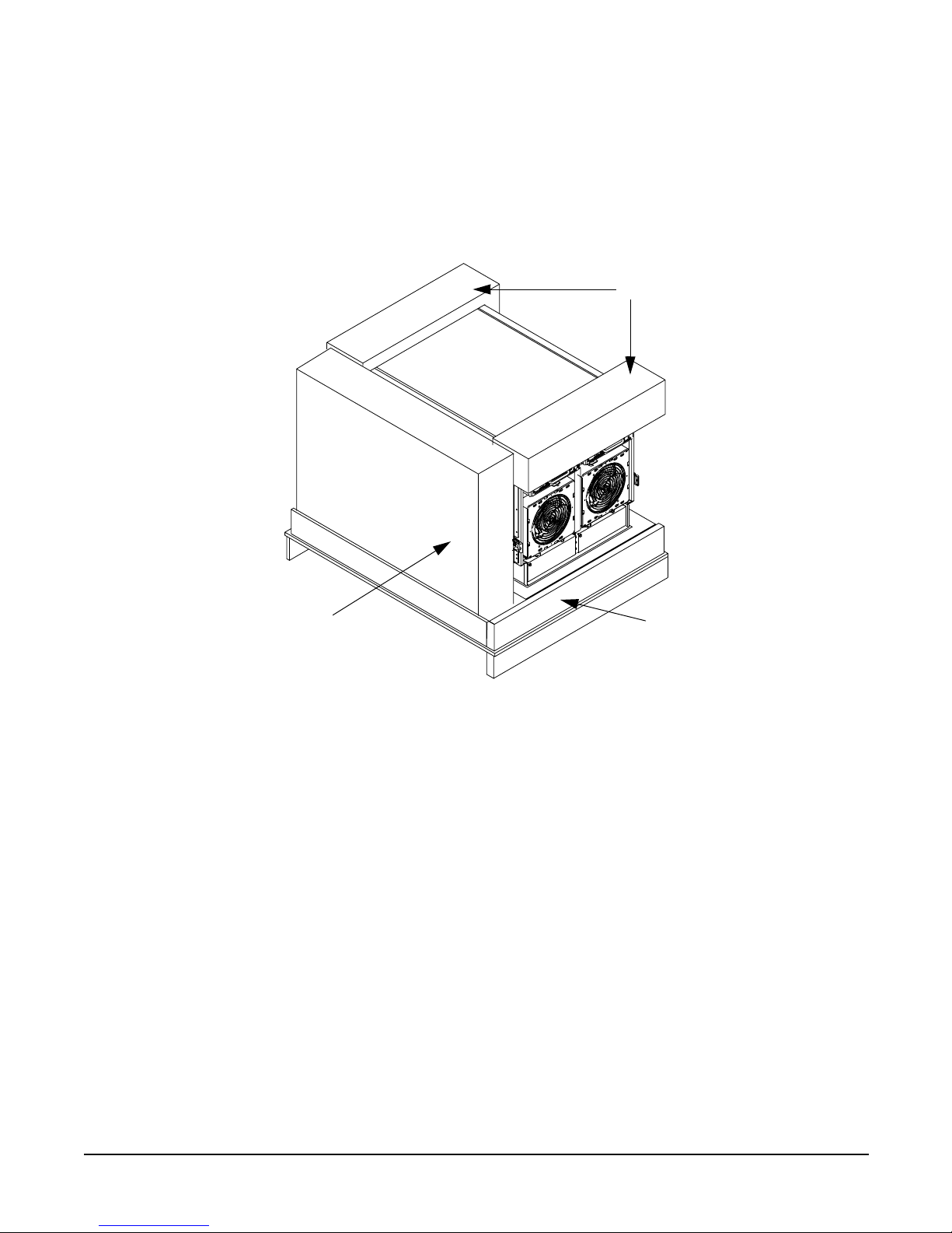
1. Cut and remove the polystrap bands securing the HP Server to the pallet.
2. Lift the carton top from the cardboard tray resting on the pallet.
3. Remove the Wheel Kit carton and the top cushions from the pallet.
Figure 1-1 Component Locations
4. Unfold bottom cardboard tray.
MWK001
3/10/03
Top Cushions
Cardboard Tray
Bezel
Kit
Page 6

Chapter 1
Wheel Kit Installation Guide
Wheel Kit Installation
6
5. Carefully tilt the server and place one of the foam blocks (A6093-44002) under the left side of the server.
Do not remove any other cushions until instructed to do so.
Figure 1-2 Position foam block on left side of server
MWK002
3/11/03
Foam Block
Cardboard Tray
Page 7

Chapter 1
Wheel Kit Installation Guide
Wheel Kit Installation
7
6. Carefully tilt the server and place the other foam block provided in the kit under the right side of the
server.
Figure 1-3 Position foam block on right side of server
MWK003
3/11/03
Foam
Block
Page 8

Chapter 1
Wheel Kit Installation Guide
Wheel Kit Installation
8
7. Remove the cushions from the lower front and rear of the server. Do not disturb the side cushions.
Figure 1-4 Remove lower front and rear foam blocks
8. Locate and identify the caster assemblies.Use the following table to identify the casters
NOTE The caster part number is stamped on the caster mounting plate
Table 1-2
Caster
(Light Color)
Part Number
Caster
(Dark Color)
Part Number
Right Front A6753-04001 Right Front A9903-04002
Right Rear A6753-04005 Right Rear A9903-04003
Left Front A6753-04006 Left Front A9903-04004
Left Rear A6753-04007 Left Rear A9903-04005
MWK004
3/12/03
Page 9

Chapter 1
Wheel Kit Installation Guide
Wheel Kit Installation
9
9. Locate and remove one of the four screws from the plastic pouch. Attach the a caster to the server.
Figure 1-5 Attaching a Caster to the Server
10. Attach the remaining casters to the server using screws supplied in the plastic pouch.
11. Remove the foam blocks from the left and right side of the server.
12. Locate the plywood ramp.
13. Attach the ramp to the edge of the pallet.
NOTE There are two pre-drilled holes in the ramp. Use the two screws taped to the ramp to attach
the ramp to the pallet.
14. Carefully roll the server off the pallet and down the ramp.
15. Locate the caster covers.
MWK005
3/12/03
Page 10

Chapter 1
Wheel Kit Installation Guide
Wheel Kit Installation
10
16. Insert the slot on the caster cover into the front caster. Secure the cover to the server by tightening the
captive screw on the cover at the rear of the server.
Figure 1-6 Securing each Caster Cover to the Server
17. Remove the existing top and side covers and replace them with the new covers provided.
Remove and Replace the Top and Side Covers
It is necessary to remove the server covers and replace them with the painted covers provided.
CAUTION Observe all ESD safety precautions before attempting this procedure. Failure to follow ESD
safety precautions could result in damage to the server.
MWK006
3/11/03
Rear Casters
Front Casters
Caster Cover
Caster Cover
Page 11

Chapter 1
Wheel Kit Installation Guide
Wheel Kit Installation
11
Top Cover Replacement
Figure 1-7 Top Cover
Removing the Top Cover
Figure 1-8 Top Cover Retaining Screws
Step 1. Loosen the retaining screws securing the cover to the rear of the chassis.
Page 12

Chapter 1
Wheel Kit Installation Guide
Wheel Kit Installation
12
Step 2. Slide the cover toward the rear of the chassis.
Step 3. Lift the cover up and away from the chassis.
Installing the New Top Cover
Step 1. Slide the new cover into position. It should easily slide into position; however, a slow firm pressure
will be needed to properly seat the cover.
Step 2. Tighten the retaining screws securing the cover to the chassis.
Removing a Side Cover
Figure 1-9 Side Cover Retaining Screw
Step 1. Loosen the retaining screw securing the cover to the chassis.
Page 13

Chapter 1
Wheel Kit Installation Guide
Wheel Kit Installation
13
Step 2. Slide the cover from the chassis.
Figure 1-10 Side Cover Removal Detail
Installing a New Side Cover
Step 1. Slide the new cover in position.
Step 2. The cover easily slides into position; however, a slow firm pressure will be needed to properly seat
the cover.
Page 14

Chapter 1
Wheel Kit Installation Guide
Wheel Kit Installation
14
Step 3. Tighten the retaining screw securing the cover to the chassis.
Figure 1-11 Completed Server
MWK007
3/11/03
 Loading...