

Page 1

HP Networking Utilities User Guide
HP Integrity Servers with Microsoft® Windows® Server 2003 for Itanium-based systems
Manufacturing Part Number: 5991-3711
February 2007
© Copyright 2007
Hewlett-Packard Development Company, L.P.
Page 2

Legal notices
© Copyright 2007 Hewlett-Packard Development Company, L.P
Microsoft and Windows are U.S. registered trademarks of Microsoft Corporation. Intel
and Itanium are registered trademarks of Intel Corporation or its subsidiaries in the
United States and other countries.
Hewlett-Packard Company shall not be liable for technical or editorial errors or
omissions contained herein. The information in this document is provided “as is” without
warranty of any kind and is subject to change without notice. The warranties for HP
products are set forth in the express limited warranty statements accompanying such
products. Nothing herein should be construed as constituting an additional warranty.
ii
Page 3

1. Replicate Agent Settings tool
Overview. . . . . . . . . . . . . . . . . . . . . . . . . . . . . . . . . . . . . . . . . . . . . . . . . . . . . . . . . . . . . . . . . . . . . . . . . . . . 6
Tool usage. . . . . . . . . . . . . . . . . . . . . . . . . . . . . . . . . . . . . . . . . . . . . . . . . . . . . . . . . . . . . . . . . . . . . . . . . . . 8
Viewing Task Results page. . . . . . . . . . . . . . . . . . . . . . . . . . . . . . . . . . . . . . . . . . . . . . . . . . . . . . . . . . . 11
2. Network Adapter License Utility
Overview. . . . . . . . . . . . . . . . . . . . . . . . . . . . . . . . . . . . . . . . . . . . . . . . . . . . . . . . . . . . . . . . . . . . . . . . . . . 14
Tool usage. . . . . . . . . . . . . . . . . . . . . . . . . . . . . . . . . . . . . . . . . . . . . . . . . . . . . . . . . . . . . . . . . . . . . . . . . . 15
Command line syntax . . . . . . . . . . . . . . . . . . . . . . . . . . . . . . . . . . . . . . . . . . . . . . . . . . . . . . . . . . . . . . . 15
Command line arguments . . . . . . . . . . . . . . . . . . . . . . . . . . . . . . . . . . . . . . . . . . . . . . . . . . . . . . . . . . . 15
Return codes . . . . . . . . . . . . . . . . . . . . . . . . . . . . . . . . . . . . . . . . . . . . . . . . . . . . . . . . . . . . . . . . . . . . . . 16
Command line examples . . . . . . . . . . . . . . . . . . . . . . . . . . . . . . . . . . . . . . . . . . . . . . . . . . . . . . . . . . . . 16
3. SetLACState Utility
Overview. . . . . . . . . . . . . . . . . . . . . . . . . . . . . . . . . . . . . . . . . . . . . . . . . . . . . . . . . . . . . . . . . . . . . . . . . . . 20
Tool usage. . . . . . . . . . . . . . . . . . . . . . . . . . . . . . . . . . . . . . . . . . . . . . . . . . . . . . . . . . . . . . . . . . . . . . . . . . 21
Command line syntax . . . . . . . . . . . . . . . . . . . . . . . . . . . . . . . . . . . . . . . . . . . . . . . . . . . . . . . . . . . . . . . 21
Command line arguments . . . . . . . . . . . . . . . . . . . . . . . . . . . . . . . . . . . . . . . . . . . . . . . . . . . . . . . . . . . 21
Command line examples . . . . . . . . . . . . . . . . . . . . . . . . . . . . . . . . . . . . . . . . . . . . . . . . . . . . . . . . . . . . 21
Contents
4. Network Adapter Scripting Utility
Overview. . . . . . . . . . . . . . . . . . . . . . . . . . . . . . . . . . . . . . . . . . . . . . . . . . . . . . . . . . . . . . . . . . . . . . . . . . . 24
Introduction . . . . . . . . . . . . . . . . . . . . . . . . . . . . . . . . . . . . . . . . . . . . . . . . . . . . . . . . . . . . . . . . . . . . . . . . 25
Order of NICs on target systems . . . . . . . . . . . . . . . . . . . . . . . . . . . . . . . . . . . . . . . . . . . . . . . . . . . . . . 25
Teams on target systems . . . . . . . . . . . . . . . . . . . . . . . . . . . . . . . . . . . . . . . . . . . . . . . . . . . . . . . . . . . . 25
The scripting application (CQNICCMD) . . . . . . . . . . . . . . . . . . . . . . . . . . . . . . . . . . . . . . . . . . . . . . . . . 27
Script conversion issues . . . . . . . . . . . . . . . . . . . . . . . . . . . . . . . . . . . . . . . . . . . . . . . . . . . . . . . . . . . . . 27
Tool usage . . . . . . . . . . . . . . . . . . . . . . . . . . . . . . . . . . . . . . . . . . . . . . . . . . . . . . . . . . . . . . . . . . . . . . . . 27
Command line syntax . . . . . . . . . . . . . . . . . . . . . . . . . . . . . . . . . . . . . . . . . . . . . . . . . . . . . . . . . . . . . . . 28
Command line arguments . . . . . . . . . . . . . . . . . . . . . . . . . . . . . . . . . . . . . . . . . . . . . . . . . . . . . . . . . . . 28
Command line examples . . . . . . . . . . . . . . . . . . . . . . . . . . . . . . . . . . . . . . . . . . . . . . . . . . . . . . . . . . . . 29
Command line help. . . . . . . . . . . . . . . . . . . . . . . . . . . . . . . . . . . . . . . . . . . . . . . . . . . . . . . . . . . . . . . . . 30
Configuration properties . . . . . . . . . . . . . . . . . . . . . . . . . . . . . . . . . . . . . . . . . . . . . . . . . . . . . . . . . . . . . . 31
NIC configuration properties . . . . . . . . . . . . . . . . . . . . . . . . . . . . . . . . . . . . . . . . . . . . . . . . . . . . . . . . . 31
Team configuration properties . . . . . . . . . . . . . . . . . . . . . . . . . . . . . . . . . . . . . . . . . . . . . . . . . . . . . . . . 31
XML data file . . . . . . . . . . . . . . . . . . . . . . . . . . . . . . . . . . . . . . . . . . . . . . . . . . . . . . . . . . . . . . . . . . . . . . . 35
Error handling and reporting . . . . . . . . . . . . . . . . . . . . . . . . . . . . . . . . . . . . . . . . . . . . . . . . . . . . . . . . . . 38
iii
Page 4

Contents
iv
Page 5

1 Replicate Agent Settings tool
Chapter 1
5
Page 6

Replicate Agent Settings tool
Overview
Overview
The HP Network Configuration Utility (NCU) enables configuration of network adapters
and teams of network adapters installed on an Integrity server. To better support server
management, the NCU has been enhanced using the Replicate Agent Settings tool of HP
Systems Insight Manager (HP SIM). The replication tool enables HP SIM to retrieve
Web Agent configuration settings from a source server and distribute that configuration
remotely to one or more target servers.
This chapter assumes that you have a basic familiarity with HP SIM, and provides
step-by-step instructions to replicate network configuration settings from one server to a
group of target servers using the Replicate Agent Settings tool of HP SIM.
You can use the Replicate Agent Settings tool to configure target servers based on
configuration information transferred from a source server. The target system does not
have to be identical to the source system. Both NICs and teams of NICs can be
configured on the target system. The Replicate Agent Settings tool modifies the
configuration of the NICs on the target system according to the NIC properties specified
on the source system.
When the Replicate Agent Settings tool runs, NICs are identified by their relative order
in the system. The relative order is determined by the slot and port order in the system.
NICs embedded on the system board are assigned the lowest numbers, followed by NICs
ordered by their slot number with the lowest slot number listed first. Multiport NICs are
ordered by ascending port number within each slot.
NICs on the target system are configured to match the corresponding NIC number on
the source server. The first NIC on the target system is configured using data from the
first NIC on the source server; the second NIC on the target system is configured
according to the saved data for the second NIC on the source server, and so on. If the
target system has more NICs than the source server, then the extra NICs retain their
current settings. If the target system has fewer NICs than the source server, data for
additional NICs on the source server is ignored.
Teams are created on the target system consisting of the same relative NICs that are
teamed on the source server. For example, if NICs 3 and 5 are teamed on the source
server, then the same teaming information is transferred to the target server, and NICs
3 and 5 are teamed on the target system during the replication operation. In general, the
NICs on the target system team do not have to be the same type of NICs that are teamed
on the source server. However, some NICs cannot be teamed and an error is returned if
an attempt to form a team is made with invalid combinations of NICs. For example,
NICs without common speed capabilities cannot be teamed on a load balancing team.
An error is returned if the NICs forming the team on the source server are not present
on the target system. For example, if NICs 3 and 5 are teamed on the source server but
the target system has only four NICs, an error is reported and the configuration is not
applied.
When teams are configured on the target system, the team properties are set to the
values transferred from the corresponding team on the source server. Properties not
transferred (and properties specified with invalid data values) are configured using their
default settings.
6
Chapter 1
Page 7

Replicate Agent Settings tool
Overview
If there are no teams configured on the source server, no teaming information is
transferred, and configuration of the target system consist of configuring individual
NICs only.
If the transferred information defines an advanced team, but a valid Integrity Essentials
Intelligent Networking Pack license is not on the target system, an error message is
returned and the operation exits without performing any actions. For information on
how to add an Integrity Essentials Intelligent Networking Pack license to the system or
to display licenses previously installed on the system, see the Intelligent Networking
Pack User Guide, or the Integrity Essentials Network License Manager online help.
Chapter 1
7
Page 8
Replicate Agent Settings tool
Tool u s a g e
Tool usage
To replicate network configuration settings from source server to target server:
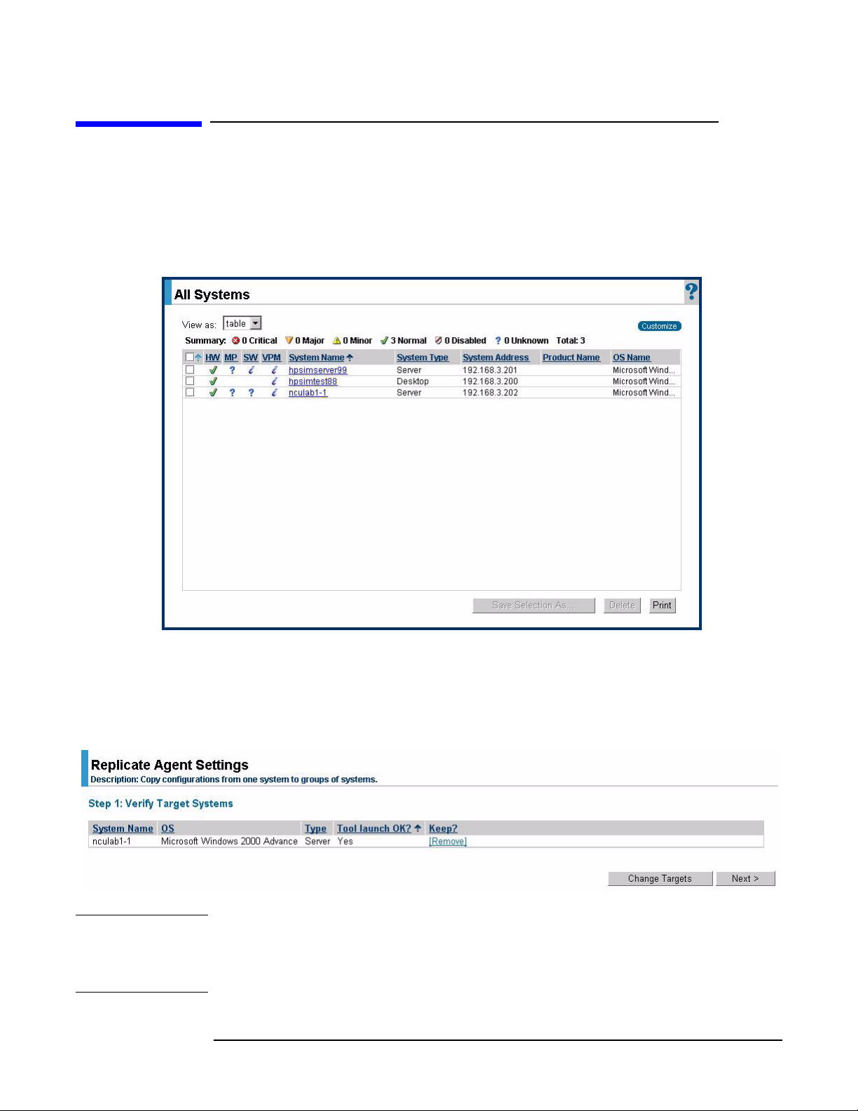
Step 1. From the HP SIM home page, select
window.
Figure 1-1 All Systems window
All Systems to display all servers in the All Systems
Step 2. Select the desired target systems from the list.
Step 3. Select
Systems” page displays with the selected targets listed.
Configure > Replicate Agent Settings from the menu, and the “Step 1: Verify Target
Figure 1-2 Step 1: Verify Target Systems window
NOTE If the systems selected are not compatible with the Replicate Agent Settings tool, the
“Tool launch OK?” column provides a brief explanation of the problem. To change the
targeted list, click
“Keep?” column.
8
Change Targets. To remove the selected system, click Remove in the
Chapter 1
Page 9
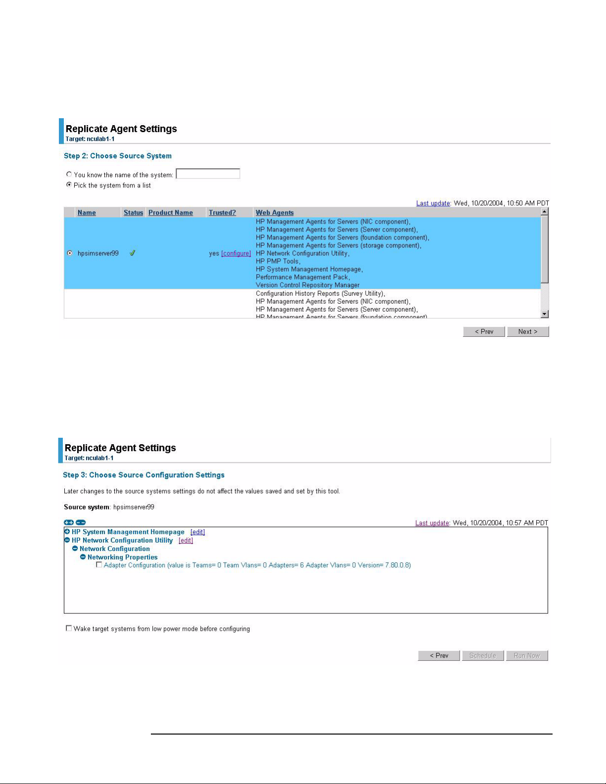
Step 4. Click Next. The “Step 2: Choose Source System” displays.
Figure 1-3 Step 2: Choose Source System window
Replicate Agent Settings tool
Tool u s ag e
Step 5. Select the specific server with a configured network to replicate on the target servers
(the Web Agent that supports network configuration is the one labeled “HP Network
Configuration Utility”).
Step 6. Click
Next. The “Step 3: Choose Source Configuration Settings” page appears.
Figure 1-4 Step 3: Choose Source Configuration Settings window
Step 7. Expand the HP Network Configuration Utility tree to view the networking components
that can be replicated. These components are located under Networking Properties.
Chapter 1
9
Page 10

Replicate Agent Settings tool
Tool u s a g e
An overview of the networking configuration provides the following information:
• Teams — number of teams in the configuration
• Team VLANs — total number of team VLANs defined (multiple teams can use the
same VLAN)
• Adapters — total number of adapters in the configuration
• Adapter VLANs — total number of adapter VLANs defined (multiple adapters can
use the same VLAN)
• Version — version of the teaming utility
NOTE Currently, the edit function is not operational for network configuration settings.
Step 8. Select
Adapter Configuration. You also can select Wake target systems from low power mode
before configuring the target servers. This option initiates the Wake-on LAN (WOL)
feature to remotely power up the target servers, if they are equipped with a
WOL-enabled NIC or if they have ACPI support in the operating system. See the section
“Replicate Agent Settings - Reference” in the HP SIM online help file for more
information.
Step 9. Select one of the following options to execute the task:
•Click
Schedule to specify when the task will run. For more information, see the
“Scheduling a Task” section in the HP SIM online help file.
•Click
Run Now to run the task immediately. The Task Results page displays. See the
“Task Results List” section in the HP SIM online help file for more information.
•Click
Prev to return to the previous page.
NOTE The Replicate Agent Settings task in HP SIM uses Secure Task Execution (STE) to issue
its commands to the system. STE enables an HP SIM system to securely request
execution of the task from a managed system. It ensures that the user requesting the
task has the appropriate rights to perform it. For more information, see the “About
Secure Task Execution” section in the HP SIM online help file.
10
Chapter 1
Page 11
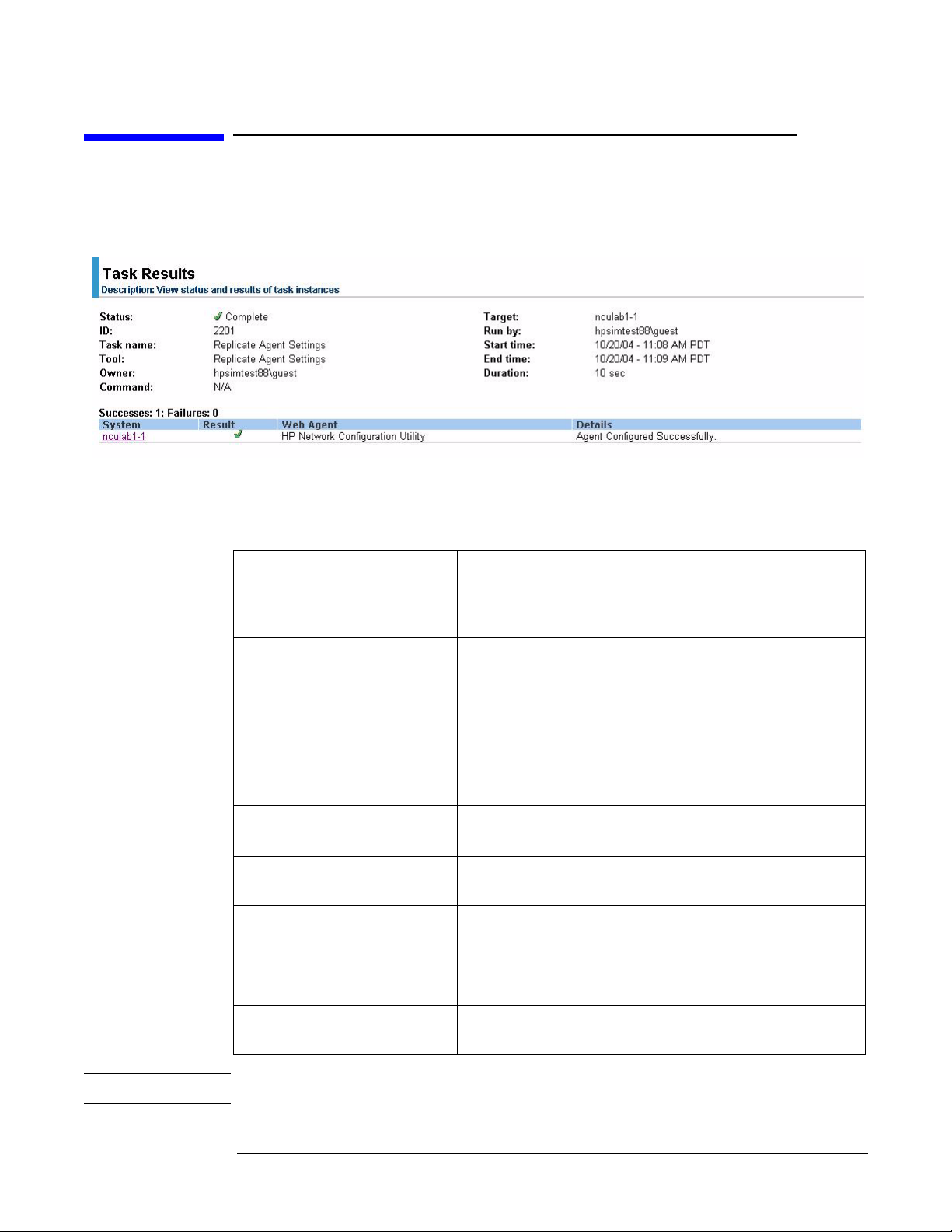
Viewing Task Results page
The Task Results page displays the task instance results of each targeted server.
Figure 1-5 Task Results page
Status information messages indicate the success or failure of the configuration and may
include one of the following messages:
Replicate Agent Settings tool
Tool u s ag e
Table 1-1 Status information messages
Status Message
Agent Configured
Successfully
Networking Configuration
Replication Error
Network Configuration — Agent Configured
Successfully.
Network Configuration Replication Error — Error
retrieving system model. Insure that network
configuration utilities are not executing on this target.
Network Configuration Error — System is not
licensed for Intelligent Networking.
Network Configuration Error — Adapter
configuration version mismatch.
Network Configuration Error — Adapter
configuration error; see log file for additional details.
Network Configuration Error — Another Networking
application is executing.
Network Configuration Error — Unidentified error;
see log file for additional details.
Network Configuration Error — Number or type of
adapter mismatch.
HP SIM Connecting VLAN
Error
NOTE See CPQSYSTEM\log\remnetcfg.log for additional error details.
Chapter 1
Network Configuration Replication Error —
Processing HP SIM connection.
11
Page 12

Replicate Agent Settings tool
Tool u s a g e
12
Chapter 1
Page 13

2 Network Adapter License Utility
Chapter 2
13
Page 14

Network Adapter License Utility
Overview
Overview
Use the Network Adapter License Utility for Windows® (nalicense) to add an Integrity
Essentials Intelligent Networking Pack to the system, or display licenses previously
installed on the system. This utility is a Windows-based command line utility and can be
run at the command line of a Command Prompt window or from a Windows command
file.
14
Chapter 2
Page 15

Network Adapter License Utility
Tool u s ag e
Tool usage
The nalicense command determines if a license is a valid Integrity Essentials
Intelligent Networking Pack license, and if it is valid, adds it to the system. It then
writes the results to a default log file (nalicense.log) in the
%SystemRoot%\cpqsystem\log directory. All messages, whether successful or error, are
written both to the stdout/stderr and to the log file. Each time you run the utility the log
file is appended with a date and time stamp. You can override the default log file location
by specifying an alternate location with the /l option.
The utility parses the command line and if the license and the action are valid, performs
the desired action. Because this is a command line application it is appropriate for
inclusion in the GuiRunOnce section of the unattend.txt file, and can be used to add an
Integrity Essentials Intelligent Networking Pack license during installation of the
operating system.
NOTE The nalicense utility should be executed before running the CQNICCMD utility to
duplicate NIC teaming configuration on a target server. For additional information about
the CQNICCMD utility, see “Network Adapter Scripting Utility” on page 23.
Executable name: nalicense
Execution environment: Win32 command line
Directory information: %SystemRoot%\system32
Command line syntax
Use one of the following formats at the command line:
nalicense add <license string> [/l <log-file>] [/? | /help]
or:
nalicense display [/l <log-file>] [/? | /help] [/M]
Command line arguments
Use the following command line arguments:
Table 2-1 nalicense command line arguments
Argument Function
<license string> Identifies the Integrity Essentials Intelligent
Networking Pack license string to add to the system
and is only valid with the add subcommand. The
license string must be in dash-separated form:
“AAAAA-BBBBB-CCCCC-12345-12345”
/l <log-file> Specifies location to write success/error message
(optional).
/? Displays utility usage (optional).
Chapter 2
15
Page 16

Network Adapter License Utility
Tool u s a g e
Table 2-1 nalicense command line arguments (Continued)
Argument Function
/help Displays utility usage (optional).
/M Prints license information in a format capable of being
parsed by machine (optional).
Return codes
The following return codes may display:
Table 2-2 nalicense return codes
Code Description
0 Success.
1 Duplicate license exists.
2 Invalid Integrity Essentials Intelligent Networking Pack license.
3 Unrecognized Integrity Essentials Intelligent Networking Pack license.
4 Usage error.
Command line examples
The following are valid nalicense command line examples:
Example #1:
nalicense add <license string>
What it does:
Adds the provided license to the system and upon successful operation writes the
following message to both stdout and to the default log file:
Mon Sep 15 15:42:14 2003: Adding License “AAAAA-BBBBB-CCCCC-12345-12345”.
Success
Example #2:
nalicense display /m /l license.txt
What it does:
Displays all valid licenses on the system and upon successful operation writes the
following example message to both stdout and to the license.txt file located in the
same directory as nalicense.exe:
License String;Product Name;Ver;Type;Seats
Used;Days;Permitted;LeftAAAAA-BBBBB-CCCCC-12345-12345; Intelligent
Networking Pack;1;Demo;1;N/A;90;35
Example #3:
nalicense display /l license.txt
16
Chapter 2
Page 17

What it does:
Displays all valid licenses on the system and upon successful operation writes the
following example message to both stdout and to the license.txt file located in the
same directory as nalicense.exe:
License Details:
License #1
License String: AAAAA-BBBBB-CCCCC-12345-12345
Product Name: Intelligent Networking Pack
Product Version: 1
Product Type: Flexible
Seats Permitted: 1
Seats Used: 1
Days Permitted:
Days Left: Unlimited
Network Adapter License Utility
Tool u s ag e
Chapter 2
17
Page 18

Network Adapter License Utility
Tool u s a g e
18
Chapter 2
Page 19

3 SetLACState Utility
Chapter 3
19
Page 20

SetLACState Utility
Overview
Overview
If a server contains more than one server adapter and at least one of those adapters is
not connected, the server may display as failed on some network management consoles,
and SNMP traps may also be triggered. Use the SetLACState utility (SetLACState) to
disable the Local Area Connection containing the unused adapter. This stops the server
from displaying as failed and prevents the SNMP traps also.
NOTE The server adapter identified by the Local Area Connection must be an HP-supported
adapter. Also, this utility cannot be used to enable or disable adapter teams.
The SetLACState utility is installed as part of the Network Configuration Utility (NCU)
component package for Windows Server 2003. Upon installation, SetLACState.exe is
copied into the %SystemRoot%\System32\ directory.
20
Chapter 3
Page 21

Tool usage
The SetLACState utility can be run from the command prompt or it can be used during
RDP installations. It can also be added to the [GuiRunOnce] section of unattend.txt for
use in unattended installations.
Command line syntax
Use the following format at the command line:
SetLACState <Local Area Connection> [Enable | Disable] [/l <logfile>]
[/? | /help]
Command line arguments
Use the following command line arguments:
Table 3-1 SetLACState command line arguments
SetLACState Utility
Tool u s ag e
Argument Function
<Local Area
Connection>
[Enable | Disable] Enables or disables the specified Local Area
[/l <logfile>] Lets you to specify where the logfile is saved. The
/? Displays utility usage (optional).
/help Displays utility usage (optional).
The name or ID of the LAN Connection (for example,
Local Area Connection or 1, 2, or 3).
NOTE: If using this utility in the [GuiRunOnce]
section of unattend.txt, you must specify the ID of
the Local Area Connection. Specifying just the name
of the Local Area Connection results in an error. For
example, “Local Area Connection” has an ID of 1.
“Local Area Connection 2” has an ID of 2, and so on.
Local Area Connections that have been renamed no
longer have an ID.
Connection.
default location is on the system drive at:
%SystemRoot%\cpqsystem\log\setlacstate.log.
Command line examples
The following are valid SetLACState command line examples that achieve the same
result:
Example #1:
SetLACState 2 disable
Chapter 3
21
Page 22

SetLACState Utility
Tool u s a g e
Example #2:
SetLACState “Local Area Connection 2” disable
What they do:
Both of these commands will disable Local Area Connection 2.
NOTE Specifying “Enable” for a connection that is already enabled, or “Disable” for a
connection that is already disabled, will not generate an error.
22
Chapter 3
Page 23

4 Network Adapter Scripting Utility
Chapter 4
23
Page 24

Network Adapter Scripting Utility
Overview
Overview
Use the Network Configuration Utility to configure network adapters (NICs) and teams
of network adapters. The utility’s scripting feature lets you do this using a batch process.
The scripting functionality also lets you configure target systems based on configuration
information saved from a source server. When scripting runs, the NIC properties
specified in the data file from the source server are used to modify the configuration of
the NICs on the target system. Target systems do not have to be identical to the source
server, and the configuration of the source server does not have to be duplicated in its
entirety onto the target system.
Advanced teaming capabilities are available through the NCU with a valid HP Integrity
Essentials Intelligent Networking Pack license. The Network Adapter License utility
(nalicense) can be used to add a license to the system or display information about
licenses previously installed on the system. For information about how to use the
Network Adapter License Utility, see “Network Adapter License Utility” on page 13.
NOTE If licensed features are used, execute the Network Adapter License (nalicense) utility
first. Then run the CQNICCMD utility to duplicate NIC teaming configuration on a
target server.
24
Chapter 4
Page 25

Network Adapter Scripting Utility
Introduction
Introduction
When using scripting to configure the target systems, NICs are identified by their
relative order in the system. The relative order is determined by the slot and port order
in the system. NICs on the system board are assigned the lowest numbers, followed by
the remaining NICs that are ordered from lowest slot number to highest. Multi-ported
NICs are ordered by ascending port number within each slot.
Order of NICs on target systems
NICs on the target system are configured to match the corresponding NIC number on
the source server using the following conventions:
• The first NIC on the target system is configured using data from the first NIC on the
source server.
• The second NIC on the target system is configured according to the saved data for the
second NIC on the source server, and so on.
• If the target system has more NICs than the source server, the extra NICs retain
their current settings.
• If the target system has fewer NICs than the source server, data for additional NICs
on the source server is ignored.
Teams on target systems
The target system is configured with the same number of teams present on the source
server using the following conventions:
• Teams are created on the target system consisting of the same relative NICs that
were teamed on the source server. For example, if NICs 3 and 5 were teamed on the
source server, then that teaming information is saved in the data file, and NICs 3 and
5 are teamed on the target system
• In general, the NICs on the team on the target system do not have to be the same
type of NICs that were teamed on the source server. However, some NICs cannot be
teamed, and if an attempt is made to form a team with invalid combinations of NICs,
an error occurs. For example, teams with no common speed capabilities cannot be
teamed on a load balancing team.
• An error occurs in the configuration if the NICs forming the team on the source
server are not present on the target system. For example, if NICs 3 and 5 are teamed
on the source server but the target system has only four NICs, an error is reported
and the configuration is not applied.
• When teams are configured on the target system, the team properties are set to the
values read from the data file for the corresponding team on the source server.
Properties not specified in the data file (and properties specified with invalid data
values) are configured using their default settings.
• If no teams are configured on the source server, then no teaming information is
written to the data file and configuration of the target system consists of configuring
individual NICs only.
Chapter 4
25
Page 26

Network Adapter Scripting Utility
Introduction
• If the data file defines an advanced team, but a valid HP Integrity Essentials
Intelligent Networking Pack license is not installed on the target system, an error
message is written to the log and the script exits without performing any actions. See
the Intelligent Networking Pack User Guide located on your Smart Setup CD for
information about how to add an HP Integrity Essentials Intelligent Networking
Pack license to the system, or display information about licenses already installed on
the system.
26
Chapter 4
Page 27

Network Adapter Scripting Utility
The scripting application (CQNICCMD)
The scripting application (CQNICCMD)
CQNICCMD is a Windows Server 2003 utility that uses a script file to duplicate the NIC
teaming configuration information of one Integrity source server and copy it to another
Integrity target server.
Script conversion issues
Scripts created with earlier versions of the Network Configuration Utility (NCU) are
supported. However, HP recommends that you recreate them using the latest version of
the NCU. Several operating modes in scripts generated with NCU versions 7.7x and
earlier have been changed, and are converted as follows:
• “Manual” is converted to “Network Fault Tolerance Only (NFT)”
• “SmartSwitch” is converted to “Network Fault Tolerance Only with Preference Order”
• For Smart Switch Teams, the existing “PreferredPrimaryNic” attribute determines
which team member should be ranked higher than others within the
“PreferredPrimaryRanking” attribute
All other unspecified parameters use their defaults.
Tool usage
This utility is run from the command line in a Command Prompt window, or using the
Run option on the Windows Start menu, or from a Windows command file. HP
recommends that you use this application as part of a SmartStart Scripting Toolkit
(SSST) deployment. However, the application can be used outside of this environment.
NOTE To execute the CQNICCMD utility from the command line, the HP Network
Configuration Utility must be closed.
To use the scripting application, complete the following steps:
Step 1. Configure NIC teaming on the source server.
Step 2. Generate a script file on the source server by clicking
Configuration Utility user interface, or by running CQNICCMD /S<filename> in the
Command Line utility.
Step 3. Modify the script file as necessary.
NOTE If you modify the script file, HP recommends that you run CQNICCMD /P to check the
syntax of the modified file and check the log file for errors and warnings. The default
location of the log file is \cpqsystem\log\cpqteam.log on the system drive. The syntax
of the /P option is: cqniccmd /p<filename>.
Save in the HP Network
Step 4. Install the HP Network Configuration utility on the target system.
Step 5. Run the Command Line utility with the following syntax: cqniccmd /C <filename>
Step 6. Check the log file for errors and warnings. The default location of the log file is
\cpqsystem\log\cpqteam.log on the system drive.
Chapter 4
27
Page 28

Network Adapter Scripting Utility
The scripting application (CQNICCMD)
NOTE If you want to use this tool in combination with the Smart Setup Scripting Toolkit
(SSSTK), see the SSSTK documentation found on your Smart Setup CD.
Command line syntax
Use the following format at the command line:
cqniccmd [/F] [/C<filename>] [/D] [/L<filename>] [/P<filename>]
[/S<filename>] [/?]
NOTE Only one of the following configuration options can be specified at a time: /S, /D, /C, or
/P.
The /L option can be used with any of the configuration options. The /F option can only
be used with the /C option.
Command line arguments
Use the following command line arguments:
Table 4-1 cqniccmd command line arguments
Argument Function
/S This option causes the source server configuration to be saved. The
name of the XML configuration data file must be specified and the
path to the data file must exist. This option is identical to saving the
source server configuration by clicking
Configuration Utility user interface.
/D This configuration option causes all teams on the target server to be
dissolved, all VLANs to be removed, and 802.1p/q Packet Tagging to
be disabled for all NICs that had VLANs. No additional arguments are
required or allowed with this option.
/C This configuration option applies the configuration specified in the
data file to the target system. An existing XML configuration data file
must be specified following the target switch. A space following the
switch is optional.
NOTE: Any teams that exist on the target system are dissolved before
the configuration is applied. Therefore, any VLAN that exists on the
team is removed, and 802.1p/q Packet Tagging is disabled. If any
VLANs are defined for non-teamed NICs, all existing NIC VLANs are
removed and 802.1p/q Packet Tagging is disabled.
Save in the HP Network
/P This option is identical to the /C option, except that the configuration
options are not applied to the target system. This is useful for syntax
checking the XML data file.
28
Chapter 4
Page 29

The scripting application (CQNICCMD)
Table 4-1 cqniccmd command line arguments (Continued)
Argument Function
/L This option is used to change the name and location of the cpqteam.log
default log file that is created in \cpqsystem\log on the system drive.
The supplied path must exist. An invalid log file name causes the
configuration to terminate with no changes. HP recommends this
option only in batch files.
/F This option causes all errors, including those errors normally treated
as non-fatal errors, to be treated as fatal errors. This option can only
be used with the /C option.
Command line examples
The following are valid cqniccmd command line examples:
Example #1:
/S
Network Adapter Scripting Utility
cqniccmd /Sc:\HP\teamcfg.xml
cqniccmd /S c:\HP\teamcfg.xml
cqniccmd /S”c:\HP\teamcfg.xml”
Example #2:
/D
cqniccmd /D
Example #3:
/C
cqniccmd /Cc:\HP\teamcfg.xml
cqniccmd /C c:\HP\teamcfg.xml
cqniccmd /C”c:\HP\teamcfg.xml”
Example #4:
/P
cqniccmd /Pc:\HP\teamcfg.xml
cqniccmd /P c:\HP\teamcfg.xml
cqniccmd /P”c:\HP\teamcfg.xml”
Example #5:
/L
cqniccmd /Cc:\HP\teamcfg.xml /Lc:\HP\config.log
cqniccmd /C c:\HP\teamcfg.xml /L c:\HP\config.log
cqniccmd /C”c:\HP\teamcfg.xml” /L” c:\HP\config.log”
Chapter 4
29
Page 30

Network Adapter Scripting Utility
The scripting application (CQNICCMD)
Command line help
Use the following option to display usage information: c/?
For example:
cqniccmd /?
displays detailed usage information for the command.
30
Chapter 4
Page 31

Network Adapter Scripting Utility
Configuration properties
Configuration properties
The XML data file contains configuration properties for individual NICs and NIC teams.
NIC configuration properties
The properties configured on the target server NICs from the source server data are
properties that are common to all HP NICs.
These properties include:
• SpeedDuplex — determines the current speed and duplex of the NIC. Possible
values include Auto/Auto, 10/Half, 10/Full, 100/Half, 100/Full, 1000/Full. The default
is Auto/Auto. The value must be valid for the NIC on the target system.
• PreferedPrimaryRanking — determines the preferred primary ranking of the
NIC. This value is written only for NICs that are teamed.
• DualChannelGroup — if dual channel teaming is used, this identifies the group to
which the NIC belongs. The default is 0. This value is written only for NICs that are
teamed. For non-Dual Channel Teams, the value is always 0.
• ConfiguredPortCost — defines the port cost for the NIC. The default is 0. This
value is written only for NICs that are teamed.
• DefaultVlanID — determines the VLAN ID used for any un-tagged packets received
by the NIC. This only applies to NICs which have VLANs defined.
• VlanID — specifies the VLAN identifier value for the device.
• VlanName — specifies the descriptive name for the VLAN ID. Every VLAN must
have a name assigned to it. Duplicate names are allowed if you want to use the same
names for different VLAN IDs.
• NetworkAddress — this value is written only for NICs that are not teamed. It
allows the burned-in address to be overridden with a locally administered address. A
null value will always be written to the XML data file because locally administered
addresses must be unique. A null value is valid and indicates the network address
will be the burned-in address. This value must be a valid unicast address if it is
edited.
Team configuration properties
Team configuration properties configured on the target server include:
• TeamName — determines the unique identifier for the NIC team. Each team name
on the target system must be unique.
• OpMode — determines operating mode of the team. Possible values are Auto,
StaticDualSlb, DynamicSingleSlb, StaticSingleSlb, FailOnFault, PrefPrimary, and
TransmitLoadBalancing.
If the OpMode is StaticDualSlb, the team is considered to be using advanced teaming.
A valid HP Integrity Essentials Intelligent Networking Pack license must be on the
Chapter 4
31
Page 32

Network Adapter Scripting Utility
Configuration properties
• LoadBalAlgorithm — determines the team load balancing algorithm. Possible
• TeamNetworkAddress — establishes the MAC address for the NIC team. A value
• TxPathValidationMode — enables or disables the packet signal transmitted
• RxPathValidationMode — enables or disables the packet signal received between
• TxPathValidationInterval — determines how frequently the packet signals are
• RxPathValidationInterval — determines how frequently the packet signals are
target system for advanced teaming options to be configured on the target server. If a
valid license does not exist, an error message is written to the log and the script exits
without performing any actions.
values are MACAddress, IPAddress, TCPConnection, RoundRobin, and Auto.
is always written to the XML data file. A null value is valid and causes a default
address to be computed. This value must be a valid unicast address if it is edited.
between the team NICs. Possible values are Enabled or Disabled.
the team NICs. Possible values are Enabled or Disabled.
transmitted. The range of acceptable values is 3 to 60. Values less than 3 are set to 3,
and values greater than 60 are set to 60.
received. The range of acceptable values is 3 to 60. Values less than 3 are set to 3, and
values greater than 60 are set to 60.
• RxPathValidationVlanID — determines the VLAN on which Receive Path
Validation Heartbeat Frames are transmitted. This value is only written when a
VLAN is defined for the team. The default is the VLAN on the team with the lowest
VLAN ID at the time the team is created.
• FastPathEnabled — enables or disables the port cost with path cost monitoring
feature. Possible values are Enabled or Disabled.
If the FastPathEnabled is set to Enabled, the team is considered to be using advanced
teaming. A valid HP Integrity Essentials Intelligent Networking Pack license must
be installed on the target system for advanced teaming options to be configured on
the target server. If a valid license does not exist, an error message is written to the
log and the script exits without performing any actions.
• FastPathSpanningTreeType — determines the spanning tree protocol. Possible
values are IEEE 802.1D and Cisco PVST+. The default is IEEE 802.1D.
FastPathSpanningTreeType is only relevant if FastPathEnabled is enabled.
• FastPathVlanID — determines the VLAN ID used for path cost monitoring. This
value is written only if a VLAN is defined for the team. FastPathVlanID is only
relevant if FastPathEnabled is enabled.
• ActivePathEnabled — allows the team member to send a packet to a remote node
and receive a reply to determine if the team member sending the packet has a path to
the echo node. The absence of a reply within the specified time period can be used to
determine when a team member should be disabled. Possible values are Enabled or
Disabled. The default is Disabled. If Enabled, a valid echo node IP address must be
entered.
If the ActivePathEnabled is set to Enabled, the team is considered to be using
advanced teaming. A valid HP Integrity Essentials Intelligent Networking Pack
license must be installed on the target system for advanced teaming options to be
configured on the target server. If a valid license does not exist, an error message is
32
Chapter 4
Page 33

Network Adapter Scripting Utility
Configuration properties
written to the log and the script exits without performing any actions.
The following values are written only when the ActivePathEnabled option is used:
— EchoNodeResponseMech — determines which echo node response mechanism
to use: DirectedARP or CommunityAddressARP. If CommunityAddressARP is
chosen, Community Probe IP Address, Community Probe MAC Address, and Use
Default fields are used.
— EchoNodeProbeIPAddress — determines the IP address to which the Echo
Node responds. This is a reserved address that can be used by all teams on a
subnet. This must be a valid unicast IP address and is enforced by scripting. This
field is only used when both Active Path and Community Address ARP response
mechanism are selected.
— EchoNodeProbeAddress — determines the MAC address to which the Echo
Node responds. This is a reserved address that can be used by all teams. This
must be a valid unicast address and is enforced by scripting. This field is only
used when both Active Path and Community Address ARP response mechanism
are selected and EchoNodeUseDefMac = No.
— EchoNodeUseDefMac — determines whether to use the reserved MAC address
defined in NTID or whether to allow the user to specify the address. This field is
only used when both Active Path and Community Address ARP response
mechanism are selected. Valid values are Yes and No: Yes = use the default MAC
address, No = use the EchoNodeProbeAddress.
— EchoNodeAddress — (Optional) determines the MAC address of the echo node.
— EchoNodeIPAddress — (Required) determines the IP address of the echo node.
• EchoNodeTime — defines the time interval between packet transfers to the echo
node. The default is 3 seconds.
• EchoNodeTimeout — defines the maximum time to wait for a response from the
echo node before considering the team member failed. The default is 3 seconds.
• ActivePathVlanID — determines the VLAN ID used for the Active Path validation.
This value is written only if a VLAN is defined for the team. ActivePathVlanID is
only relevant if ActivePathEnabled is enabled.
• CriteriaRanking — determines the priority of the redundancy mechanisms used in
selecting the next port to become the Primary port. Possible values are: 2 = User
Preference Order, 1 = Active Path, 0 = Fast Path. Format is 0:1:2.
• DefaultVlanID — determines the VLAN ID used for any un-tagged packets received
by the team. This only applies to teams which have VLANs defined.
• RouterPathEnabled — enables or disables the router path protocol feature.
Possible values are Enabled or Disabled. If RouterPathEnabled is set to Enabled, the
team is using advanced teaming. A valid Integrity Essentials Intelligent Networking
Pack license must be on the target system to configure advanced teaming options on
the target server. If a valid license does not exist, an error message is written to the
log and the script exits without performing any actions.
• RouterPathProtocol — determines the router path protocol. Possible values are
HSRPv1 and VRRP. The default is HSRPv1. RouterPathProtocol is relevant only
when RouterPathEnabled is Enabled.
Chapter 4
33
Page 34

Network Adapter Scripting Utility
Configuration properties
• RouterPathIPAddress — determines the IP address for the router path. This
• RouterPathVlanID — determines the Vlan ID used for the router path validation.
• CDPv1Enabled — enables or disables the CDPv1 discovery protocol feature.
• CDPv2Enabled — enables or disables the CDPv2 discovery protocol feature.
option is written only if RouterPathEnabled is enabled.
This option is written only if a VLAN is defined for the team. RouterPathVlanID is
relevant only when RouterPathEnabled is Enabled.
Possible values are Enabled or Disabled. If CDPv1Enabled is set to Enabled, the
team is using advanced teaming. A valid Integrity Essentials Intelligent Networking
Pack license must be on the target system to configure advanced teaming options on
the target server. If a valid license does not exist, an error message is written to the
log and the script exits without performing any actions.
Possible values are Enabled or Disabled. If CDPv2Enabled is set to Enabled, the
team is using advanced teaming. A valid Integrity Essentials Intelligent Networking
Pack license must be on the target system to configure advanced teaming options on
the target server. If a valid license does not exist, an error message is written to the
log and the script exits without performing any actions.
34
Chapter 4
Page 35

XML data file
The XML data file contains the configuration properties for NICs and teams and consists
of the following XML elements:
• <teamingconfig> — brackets the entire data file and is required
• <nic> — defines NIC properties
• <team> — defines teams and their properties
• <vlan> — defines VLANs and their properties
The “relnics” attribute of the <team> element lists the NICs to be configured on the
team.
The following example is a typical NIC teaming script:
<teamingconfig>
<!-- The comment lines in this file make it convenient -->
<!-- to reference <nic>, <team>, and <vlan> elements -->
<!-- within the file. It is recommended that these -->
<!-- comment lines remain unchanged if the user edits -->
<!-- the file. -->
Network Adapter Scripting Utility
XML data file
<!-- -->
<!-- Version Data -->
<!-- -->
<version UtilityVersion='8.40.0.9' ScriptVersion='3.1'/>
<!-- -->
<!-- Adapter Data -->
<!-- -->
<!-- <nic> element 1 -->
<nic>
<property id='SpeedDuplex' value='Auto/Auto'/>
<property id='NetworkAddress' value='' />
</nic>
<!-- <nic> element 2 -->
<nic>
<property id='SpeedDuplex' value='Auto/Auto'/>
<property id='PreferredPrimaryRanking' value='0'/>
<property id='DualChannelGroup' value='0'/>
Chapter 4
35
Page 36

Network Adapter Scripting Utility
XML data file
<property id='ConfiguredPortCost' value='0'/>
</nic>
<!-- <nic> element 3 -->
<nic>
<property id='SpeedDuplex' value='Auto/Auto'/>
<property id='PreferredPrimaryRanking' value='1'/>
<property id='DualChannelGroup' value='0'/>
<property id='ConfiguredPortCost' value='0'/>
</nic>
<!-- <nic> element 4 -->
<nic>
<property id='SpeedDuplex' value='Auto/Auto'/>
<property id='NetworkAddress' value='' />
</nic>
<!-- <nic> element 5 -->
<nic>
<property id='SpeedDuplex' value='Auto/Auto'/>
<property id='NetworkAddress' value='' />
</nic>
<!-- <nic> element 6 -->
<nic>
<property id='SpeedDuplex' value='Auto/Auto'/>
<property id='NetworkAddress' value='' />
</nic>
<!-- -->
<!-- Team Data -->
<!-- -->
<!-- <team> element 1 -->
<team relnics='2 3'>
<property id='TeamName' value='HP Network Team #1'/>
<property id='OpMode' value='TransmitLoadBalancing'/>
<property id='LoadBalAlgorithm' value='Auto'/>
<property id='RxHeartbeatInterval' value='3'/>
<property id='TxHeartbeatInterval' value='3'/>
36
Chapter 4
Page 37

<property id='RxHeartbeatMode' value='Enabled'/>
<property id='TxHeartbeatMode' value='Enabled'/>
<property id='TeamNetworkAddress' value='' />
<property id='FastPathEnabled' value='Enabled'/>
<property id='FastPathSpanningTreeType' value='IEEE 802.1D'/>
<property id='EchoNodeTime' value='3'/>
<property id='EchoNodeTimeout' value='3'/>
<property id='CriteriaRanking' value='9;0;1;2'/>
<property id='RouterPathProtocol' value='HSRPv1'/>
<property id='ActivePathEnabled' value='Enabled'/>
<property id='EchoNodeIPAddress' value='192.168.0.2'/>
<property id='EchoNodeResponseMech' value='CommunityAddressARP'/>
<property id='EchoNodeProbeAddress' value='00-01-FA-FE-FE-FE'/>
<property id='EchoNodeProbeIPAddress' value='192.168.0.3'/>
<property id='EchoNodeUseDefMac' value='Yes'/>
<property id='RouterPathEnabled' value='Enabled'/>
<property id='RouterPathIPAddress' value='192.168.0.4'/>
<property id='CDPv1Enabled' value='Enabled'/>
<property id='CDPv2Enabled' value='Disabled'/>
<property id='DefaultVlanId' value='10'/>
<property id='RxPathValidationVlanId' value='10'/>
<property id='FastPathVlanId' value='10'/>
<property id='ActivePathVlanId' value='10'/>
<property id='RouterPathVlanId' value='10'/>
Network Adapter Scripting Utility
XML data file
<!-- <vlan> element 1 -->
<vlan>
<property id='VlanId' value='10'/>
<property id='VlanName' value='VLAN 10'/>
</vlan>
</team>
<teamingconfig>
Chapter 4
37
Page 38

Network Adapter Scripting Utility
Error handling and reporting
Error handling and reporting
Errors can occur for a variety of reasons including differences between the source and
target system NICs or because of errors introduced by editing the XML data file. The
software performs extensive error checking as the XML data file is read and processed.
When invalid property values are detected, a WARNING error message is written to the
log file and configuration continues with either default or existing values.
When cqniccmd is run from a command line or a Windows command file, a completion
code is written as an error level code to both a log file and the screen. This error code can
be used by the Windows command file to determine how to proceed. The error level codes
are as follows:
• Successful start of the action returns an error level zero (0).
• Non-fatal errors return an error level one (1).
• An invalid log file returns an error level two (2).
• Other fatal errors return an error level three (3) or greater.
Specific information about all errors can be found in the log file.
38
Chapter 4
 Loading...