

Page 1

hp server rx4610
User Guide
Version 0501
Page 2

Notice
The information contained in this document is subject to change without notice.
Hewlett-Packard makes no warranty of any kind with regard to this material, including, but not limited to,
the implied warranties of merchantability and fitness for a particular purpose. Hewlett-Packard shall not be
liable for errors contained herein or for incidental or consequential damages in connection with the furnishing,
performance, or use of this material.
Hewlett-Packard assumes no responsibility for the use or reliability of its software on equipment that is not
furnished by Hewlett-Packard.
This document contains proprietary information that is protected by copyright. All rights are reserved. No part of
this document may be photocopied, reproduced, or translated to another language without the prior written
consent of Hewlett-Packard Company.
®
is a registered trademark of ATI Technologies, Incorporated. Intel® and Pentium® are registered trademarks
ATI
of Intel Corporation. Microsoft
®
, Windows NT®, Windows 95® , Windows 2000® and Microsoft® Internet
Explorer are registered trademarks of Microsoft in the U.S. and other countries. Netscape Navigator
registered trademark of Netscape Communications Corporation in the U.S. and other countries. Symantec
registered trademark of Symantec, Incorporated. pcANYWHERE32 is a trademark of Symantec, Incorporated.
Symbios
Adobe Systems Incorporated. Torx
®
is a registered trademark of LSI Logic Corporation. Adobe® and Acrobat® are registered trademarks of
®
is a registered trademark of CamCar/Textron, Incorporated.
Itanium™ is a trademark of Intel Corporation. 3M is a trademark or registered trademark of 3M.
© Copyright 2001, Hewlett-Packard Company.
Audience Assumptions
®
is a
®
is a
This guide is for the person who installs, administers, and troubleshoots LAN servers. HewlettPackard Company assumes you are qualified in the servicing of computer equipment and trained in
recognizing hazards in products with hazardous energy levels.
ii
Page 3

Contents
1 Controls, Ports, and Indicators ......................................................................1
Introduction ........................................................................................................1
Front Panel ....................................................................................................1
Additional Front Panel Controls and Indicators .............................................3
Rear View ......................................................................................................7
Applying Power to the HP Server ....................................................................10
Powering-Up the HP Server ........................................................................10
Powering-Down the HP Server....................................................................10
Connecting AC Power to Multiple-Server Configurations............................ 11
2 Opening and Closing the HP Server ............................................................12
Introduction ......................................................................................................12
Mounting the Front Bezel ................................................................................. 12
Removing and Replacing the Front Bezel .......................................................12
Removing and Replacing the HP Server’s Main Cover.................................. 14
Tools Required ............................................................................................14
Removing the Top Cover............................................................................. 14
Replacing the Top Cover .............................................................................15
3 Installing Fans and Power Supplies ............................................................17
Introduction ......................................................................................................17
Tools and Supplies Needed.............................................................................17
Hot Swapping the 172 mm Fans .....................................................................18
Removing the 172 mm Fans .......................................................................18
Installing the 172 mm Fans .........................................................................19
Hot Swapping the 120 mm Fans .....................................................................19
Removing the 120 mm Fans .......................................................................19
Installing the 120 mm Fans .........................................................................20
Hot Swapping Power Supplies ........................................................................21
Determining Power Supply Status ............................................................... 22
Removing a Power Supply ..........................................................................23
Installing a Power Supply ............................................................................24
4 Installing Mass Storage Devices ..................................................................25
Introduction ......................................................................................................25
Mass Storage Guidelines .................................................................................25
Boot Priority .................................................................................................25
Tools Required................................................................................................. 26
Installing a Hot Swap Hard Drive..................................................................... 26
Determining Drive Status............................................................................. 27
Removing a Hard Disk Drive .......................................................................27
Installing a Hard Disk Drive .........................................................................28
Installing Non-Hot Swap Drives .......................................................................29
iii
Page 4

Installing the Floppy Disk Drive ...................................................................29
Installing the DVD Drive ..............................................................................30
Connecting External SCSI Devices .............................................................32
Removing and Installing the Hard Disk Bay ....................................................32
Removing the Hard Disk Bay ......................................................................32
Installing the Hard Disk Bay ........................................................................33
Removing and Installing the SCSI Backplane .................................................34
Removing the SCSI Backplane ...................................................................34
Installing the SCSI Backplane Board........................................................... 34
Installing the Front Panel Board ......................................................................35
Removing the Front Panel Module ..............................................................35
Installing the Front Panel Board ..................................................................35
5 Installing Additional Memory........................................................................36
Introduction ......................................................................................................36
Tools Required ............................................................................................36
Memory Installation Guidelines ...................................................................36
Removing the Processor/Memory Complex ....................................................37
Removing the Memory Board DC-to-DC Converters ...................................... 38
Removing and Installing Memory Boards ........................................................39
Removing Memory Boards ..........................................................................39
Installing Memory Boards ............................................................................ 40
Installing and Removing DIMMs ......................................................................42
Installing DIMMs ..........................................................................................42
Removing DIMMs ........................................................................................44
Installing the Memory Board DC-to-DC Converters ........................................ 44
Installing the Processor/Memory Complex ......................................................45
6 Installing an Additional Processor............................................................... 46
Introduction ......................................................................................................46
Tools Required ............................................................................................46
Processor Configuration Guidelines ............................................................46
Removing the CPU Thermal Dummy .............................................................. 47
Installing an Additional Processor.................................................................... 48
Removing a Processor..................................................................................... 51
Installing a CPU Thermal Dummy ................................................................... 52
Installing the Processor Baseboard .................................................................52
Removing the Processor Baseboard...........................................................53
Installing the Board in a System with Three or Four Microprocessors........ 54
Installing the Board in a System with Two Microprocessors .......................55
7 Installing Accessory Boards ........................................................................57
Introduction ......................................................................................................57
Tested PCI Boards ......................................................................................57
Tools Required ............................................................................................57
Accessory Board Installation Guidelines ......................................................... 57
IRQ Settings ................................................................................................ 57
iv
Page 5

Boot Priority .................................................................................................58
Installing Accessory Boards............................................................................. 58
Installing a Hot Swap PCI Board .................................................................58
Installing a Non-Hot Plug PCI Board ...........................................................60
Removing Accessory Boards........................................................................... 63
Removing a Non-Hot Plug PCI Board .........................................................63
Removing a Hot Plug PCI Board .................................................................64
8 Server Management Boards .........................................................................65
Introduction ......................................................................................................65
Baseboard Management Controller (BMC) .................................................65
Intelligent Chassis Management Bus (ICMB) Controller ............................. 66
Hot Swap Controller (HSC) ......................................................................... 66
I/O Baseboard .................................................................................................. 68
Removing the I/O Baseboard ......................................................................68
Installing the I/O Baseboard ........................................................................70
Sideplane Board .............................................................................................. 71
Removing the Sideplane Board ................................................................... 71
Installing the Sideplane Board .....................................................................72
PCI Hot Plug LED Board.................................................................................. 72
Removing the PCI Hot Plug LED Board ......................................................72
Installing the PCI Hot Plug LED Board ........................................................73
Legacy I/O Board .............................................................................................74
Removing the Legacy I/O Board .................................................................74
Installing the Legacy I/O Board ...................................................................75
Changing the Legacy I/O Board Battery ..........................................................77
Power Distribution Board (T-Docking) .............................................................78
Removing the Power Distribution Board (T-Docking).................................. 78
Installing the Power Distribution Board (T-Docking).................................... 82
9 Connecting the Monitor, Keyboard, and Mouse ......................................... 84
Introduction ......................................................................................................84
10 Configuring the HP Server ...........................................................................86
Introduction ......................................................................................................86
Configuring the HP Server ...............................................................................86
Power-on Sequence and Power-on Self Test (POST)................................ 86
The Extensible Firmware Interface (EFI) Boot Manager .............................87
Server Management Configuration Utility.................................................... 92
Using BIOS Setup........................................................................................ 99
Using the SELViewer Utility....................................................................... 107
Using the SDR Viewer Utility .....................................................................112
Server Firmware ............................................................................................115
11 Troubleshooting.......................................................................................... 116
Introduction ....................................................................................................116
Common Installation Problems ...................................................................... 116
Troubleshooting Sequence........................................................................ 116
v
Page 6

HP Server rx4610 SEL Data Tables ..............................................................120
HP Server rx4610 Sensor Codes ..............................................................121
BIOS Error Codes\Messages ........................................................................ 125
Beep Codes ...................................................................................................129
Beep Codes and Interpretation.................................................................. 129
Types of Memory Tests .................................................................................131
First Row Memory Test.............................................................................. 131
Base Memory Test..................................................................................... 134
Extended Memory Test ............................................................................. 140
Memory Test Duration ...............................................................................143
Aborting the Memory Test .........................................................................144
Setup Dialog ..............................................................................................145
Memory Testing Error Codes\Messages ...................................................145
DIMMUTIL .................................................................................................148
12 Parts Information......................................................................................... 149
Exploded View – Hot Swap and Display........................................................149
Exploded View – Processor/Memory Access ................................................150
Exploded View – Processor/Memory Complex.............................................. 151
Exploded View – Server Management Boards.............................................. 153
Exploded View – Power Distribution Board and IDE Drives.......................... 154
Replaceable Parts List ...................................................................................155
Parts List Identifier .........................................................................................155
Appendix A Specifications ......................................................................... 158
Introduction ....................................................................................................158
Requirements ............................................................................................158
Video Display Modes .................................................................................160
Connector Pinouts and Boardset Locations ..................................................161
VGA Video Port .........................................................................................161
Keyboard and Mouse................................................................................. 162
Parallel Port ...............................................................................................163
Serial Ports A and B ..................................................................................163
Universal Serial Bus (USB) ....................................................................... 165
SCSI ..........................................................................................................166
IDE............................................................................................................. 167
PCI ............................................................................................................. 168
Information on Jumpers .................................................................................171
General Procedure to Change Jumper Settings ....................................... 171
Processor Baseboard Jumpers .................................................................171
Legacy I/O Board Jumpers........................................................................ 177
I/O Baseboard Jumpers............................................................................. 181
Power Distribution Board Jumpers (T-Docking) ........................................183
Determining DC-to-DC Status ...................................................................184
B Equipment Log and Configuration Worksheet .........................................186
Equipment Log ............................................................................................... 186
vi
Page 7

Index ..................................................................................................................188
vii
Page 8
Chapter 1: Controls, Ports, and Indicators
1 Controls, Ports, and Indicators
Introduction
Before operating the Server, familiarize yourself with the HP Server’s controls, ports, and indicators,
as shown in Figures 1-1 through 1-8.
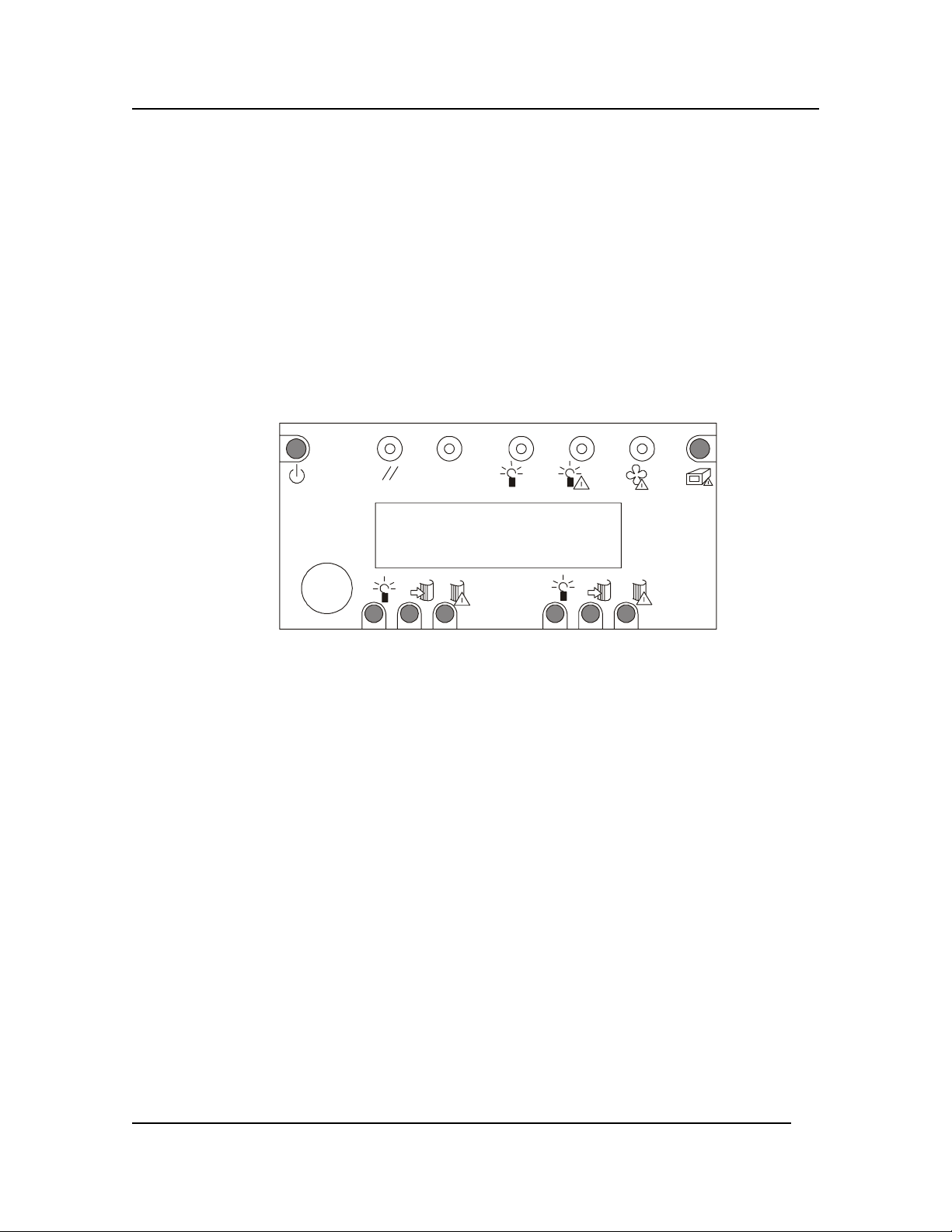
Front Panel
The front panel of the HP Server provides the controls and indicators commonly used when operating
the HP Server.
POWER
RESET INT SYS PWR PWR FAN GEN
LCD DISPLAY
PWR PWR ACTIVEACTIVE FAIL FAIL
Figure 1-1. Front Panel
Table 1-1 provides the front panel power switch and its associated LED indicator definitions.
1
Page 9

Chapter 1: Controls, Ports, and Indicators
Table 1-1. Control Panel Switch and Indicators
Control / Indicator Description
Power On/Off
Reset
INIT
System Power LED
(Green)
Power Fail LED
(Amber)
Fan Fail LED (Amber)
General Fault LED
(Amber)
Front Panel LCD
This button turns the HP Server power On or Off. The
+12 V standby voltage is On whenever the server power
cords are plugged in.
When pressed, it resets the server and causes the power on
self-test (POST) to run.
When pressed, the system performs a crash dump provided
the dump is supported by the operating system.
When lit continuously, it indicates the presence of DC
power in the server. When not lit, it indicates power is
turned off or the power source is disrupted.
When lit continuously, it indicates a power failure.
When flashing, it indicates a fan failure.
When lit continuously, it indicates a hot plug PCI fault.
It displays information about the processor type and the
POST codes.
2
Page 10

Chapter 1: Controls, Ports, and Indicators
A
Additional Front Panel Controls and Indicators
The input and storage devices provide additional front panel controls and indicators, which give
control and operational status to the respective device.
DVD Drive
The server supports a slimline IDE DVD drive. This peripheral mounts directly above the top-left
power bay on the front of the chassis. The drive is mounted on a removable tray that facilitates
system assembly and service.
Open/Close Button
POWER
RESET INT SYS PWR PWR FAN GEN
LCD DISPLAY
PWR PWR ACTIVE ACTIVE FA IL FAIL
Figure 1-2. DVD Drive
Table 1-2. HP DVD Drive
Control Indicator Description
Open/Close Button
Activity LED
When pressed, it opens or closes the DVD tray.
When lit, it indicates the drive is in use.
ctivity LED
3
Page 11

Chapter 1: Controls, Ports, and Indicators
A
Diskette Floppy Drive
The server supports a slimline IDE diskette drive for 1.44 MB and 120 MB media. This half-inch
slimline peripheral mounts directly above the top-right power bay on the front of the chassis. The
drive is mounted on a removable tray that facilitates system assembly and service.
ctivity
LED
Ejector
Button
POWER
RESET INT SYS PWR PWR FAN GEN
LCD DISPLAY
PWR PWR ACTIVE A CTIVE FAI L FAIL
Figure 1-3. Drive
Table 1-3. Floppy Diskette Drive
Control Indicator Description
Activity LED
Ejector Button
When lit, it indicates the drive is in use.
When pressed, it ejects the diskette.
4
Page 12

Chapter 1: Controls, Ports, and Indicators
SCSI Hard Drives
The server supports up to two hot-swap drive carriers containing standard 1-inch high by 3.5-inchwide LVDS SCSI hard drives. As part of the hot-swap implementation, drive carriers with integral
heat sinks house the drives. Each drive is mounted in a carrier with four fasteners and the carrier
snaps into the hard drive bay. When a carrier is seated properly in the bay, it snaps into place and
leaves the locking handle exposed to the front of the chassis. Drives can consume up to 24 watts of
power and must be specified to run at a maximum ambient temperature of 40 ° C (104 ° F).
POW ER
Power LED
Drive Active
Failure LED
RESET INT SYS PWR PWR FA N GEN
LCD DISPLAY
PWR PWR ACTIVEACTIVE FAIL FAIL
POWER
RESET INT SYS PWR PWR FAN GEN
LCD DISPLAY
PWR PWR ACTIVEACTIVE FAIL FAIL
Figure 1-4. SCSI Drive Indicators on the Front LED Panel
Table 1-4. SCSI Drives
Control Indicator Description
Failure LED
Drive Active
Power LED
Drive Power LED
(Green)
Drive Active LED
(Green)
Drive Fail LED
(Amber)
When lit continuously, it indicates the presence of
the drive and power to the drive.
When lit, it indicates drive activity.
When lit continuously, it indicates an asserted fault
status on one or more hard disk drives. When
flashing, it indicates a drive reset in progress.
5
Page 13
Chapter 1: Controls, Ports, and Indicators
Power Supplies
The chassis can be configured with three to four power supplies. Each power supply has a dual rating
of 800W minimum over an input range of 180-264VAC and 700W minimum over an input range of
90-132VAC. Each supply is designed to minimize EMI and RFI. Each power supply also has selfcontained fans for cooling.
The DC output voltages of each power supply are:
• +48 V
• +12 V standby
Each supply docks into a 28-pin connector on the front of the Power Distribution Board (T-Docking
board).
Power Supply Indicators
POWER
RESET INT SYS PWR PWR FAN GEN
LCD DISPLAY
PWR PWR ACTIVE ACTIVE FA IL FA IL
Figure 1-5. Power Supply Indicators
Table 1-5. LEDs for Power Supplies
Control Indicator Description
Power LED
(Green)
When lit continuously, it indicates the power
supply DC outputs are on and OK. Blinking
indicates the power supply is on standby. Off
indicates there is no power to the power supply.
Predictive Fail LED
(Amber)
Fail LED
(Amber)
A blinking LED indicates that the power supply
will soon fail.
When lit continuously, it indicates that the power
supply has failed and is not supplying output.
When blinking, it indicates that the power supply
has reached its current limit.
6
Page 14
Chapter 1: Controls, Ports, and Indicators
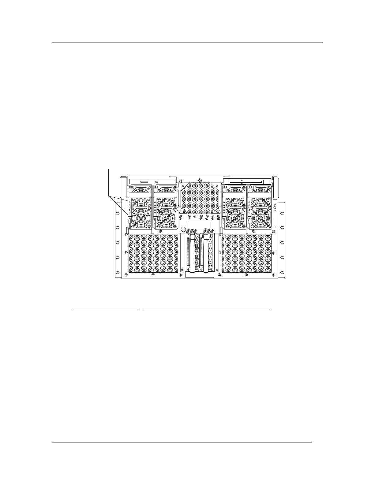
Rear View
The ports and connectors at the rear are listed below and shown in Figure 1-6. Figure 1-6 provides a
detailed view of the Legacy I/O panel that resides in the upper-right corner of the rear panel.
• The power connector accepts a standard power cable to connect the
HP Server with the site power supply.
• Ten PCI add-in board expansion slots are available. Eight are hot plug and two are non-hot
plug.
• Each hot plug PCI has status LEDs.
• The mouse port accepts a standard mouse with a PS/2 connector.
• The keyboard port accepts a standard keyboard with a 6-pin PS/2 connector.
• Two USB ports, 0 and 1, with 4 pin connectors are provided for printers, scanners, and
external modems.
• The LAN port is included as an embedded controller based on Intel's 82559 10/100 BaseT Fast
Ethernet controller. It has a RJ-45 LAN connector and two LEDs to indicate LAN speed and
valid connection.
• The two Serial Ports are standard 9-pin RS-232 connectors.
• The Parallel Port is a standard PS/2 compatible parallel port with a 25 pin bi-directional
subminiature D connector.
• There are two Interchassis Management Bus (ICMB) connectors, ports 1 and 2.
• The 15 pin video connector is Super VGA compatible.
• The optional external SCSI port provides access to external SCSI devices.
Figure 1-6. Rear Panel and Ports
7
Page 15

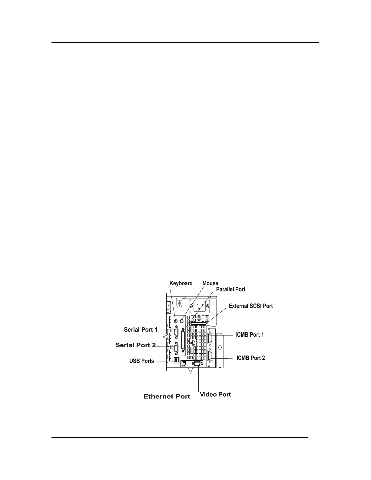
Chapter 1: Controls, Ports, and Indicators
Legacy I/O Panel
This board contains all legacy I/O connections and plugs into an edge connector on the I/O baseboard.
NOTE The keyboard and mouse connector must be plugged into the correct ports or the
server will not boot.
8
Page 16

Chapter 1: Controls, Ports, and Indicators
PCI LEDs
Each PCI slot has four indicator LEDs: two on the outside and two on the inside of the system. The
two LEDs for each slot: one amber and one green are visible from the rear (also inside) of the HP
Server, as shown in Figure 1-7. Eight of the ten PCI slots can be individually powered down through
the respective NOS or supported GUI utility, without powering down the entire HP Server, if the
board has a Hot Plug compliant driver.
Status Indicators for PCI Cards
Figure 1-7. Status Indicators for PCI Boards
9
Page 17

Chapter 1: Controls, Ports, and Indicators
Applying Power to the HP Server
Before applying power to the HP Server, verify that the keyboard and mouse are connected to the
proper ports. The server will not boot without these devices. Turning on the monitor prior to
powering on the HP Server allows proper auto-configuration of the video output as it boots.
Powering-Up the HP Server
To power-up the rx4610, complete the following procedure:
NOTE Turn on power to the monitor connected to the HP Server before you power-on the
Server. This allows proper
auto-configuration of video output of the Server as it boots.
1. Make sure that the monitor, keyboard, and mouse have been connected to the proper ports on
the rear panel of the server.
2. Remove the drive protection card, if present, from the diskette drive.
3. Plug in the power cord for the monitor and turn it on.
4. Plug the female ends of the server AC power cords into the input receptacle on the back of the
chassis.
5. Plug the male ends of the server AC power cords into grounded,
three-pronged AC power outlet.
6. Slide the server into the rack.
7. If the server does not come on when you plug it into the AC outlet, press the on/off power
switch on the front panel.
8. Verify that the power-on light on the front panel is lit. After a few seconds, the power-on self
test (POST) begins.
When you press the power button on the control panel, the Server powers up and loads the
operating system. The system runs a set of power on self tests (POST) during this process. For
details refer to Chapter 11, "Troubleshooting."
Powering-Down the HP Server
To power-down the HP Server, complete the following procedure:
1. Log off all users and, if necessary, back up the system files.
◊ Schedule the power down for a time when the Server being down will affect the fewest
users.
◊ If you will be doing any kind of hardware or software upgrade, ensure the Server's data has
been backed up.
◊ Follow instructions in your network operating system (NOS) documentation to gracefully
shut down all networking software and applications.
WARNING The power supply will continue to provide standby current to the HP Server until
the power cable is disconnected from the rear panel.
10
Page 18

Chapter 1: Controls, Ports, and Indicators
2. Logoff and exit the operating system. The following prompt appears:
Shell>
3. At the Shell> prompt, press and hold the Power button for several seconds. Holding the Power
button in for several seconds will power down the server.
4. Disconnect the power cords from the power source.
Normally this completes the power-down procedure.
Connecting AC Power to Multiple-Server Configurations
The HP Server temporarily draws a large "inrush current," when first connected to an AC power
source. This also occurs when the Server is in a standby mode (power is turned off, but the power
cord is plugged into AC power). The inrush current is much greater than the Server's normal operating
current and generally, the AC power source can handle the normal inrush current.
However, if you install several HP Servers on one circuit, precautions are necessary. If there is a
power failure and power is then restored, all the servers immediately begin to draw inrush current at
the same time. If the circuit breakers on the incoming power line have insufficient capability, the
breaker may trip and thus prevent the servers from powering up.
11
Page 19

2 Opening and Closing the HP Server
Introduction
This chapter describes how to remove and replace the front bezel and the HP Server's main cover.
Mounting the Front Bezel
The front handles, if not already installed on the HP Server, should be attached to the front of the HP
Server before mounting the bezel.
1. Place the handles into the slots on the front of the HP Server on each edge, as shown in the
figure below.
2. Insert the screws through the bracket into the top hole of each group of three holes on the front
sides of the HP Server. Repeat this procedure for both handles.
3. Hold the bezel in front of the HP Server.
4. Press the bezel firmly into place.
You should hear several clicks as the bezel snaps into place on the bracket.
Removing and Replacing the Front Bezel
The bezel is packed in the top tray.
1. To remove the bezel, pull it straightforward off the chassis.
This exposes the power supplies, mass storage devices, and fans.
2. To replace the bezel, press it back onto the chassis, allowing it to snap into place. See Figure
2-1.
12
Page 20

Chapter 2: Opening and Closing the HP Server
Figure 2-1. Removing and Replacing the Front Bezel
13
Page 21

Chapter 2: Opening and Closing the HP Server
Removing and Replacing the HP Server’s Main Cover
The server comes with a removable top cover. Removal of this cover is necessary when installing or
removing many components. You do not have to remove the top cover when removing or installing
PCI hot plug and non-hot plug adapter boards, the Legacy I/O board, fans, hard drives, power
supplies, or components inside the Processor/Memory Complex.
WARNING Before removing the cover, always disconnect the power cord and unplug the
Ethernet cables. Disconnect the power cord to avoid exposure to high energy
levels that may cause burns when parts are short-circuited by metal objects such
as tools or jewelry.
Make sure that the rack is anchored securely so that it does not tip when the server
is extended from the rack.
CAUTION For proper cooling and airflow, do not operate the server with the cover off.
Always reinstall the cover before turning on the server.
Tools Required
The following tools may be required to remove and replace the cover.
• Phillips screwdriver #2 (cross-head )
• Small flat-bladed screwdriver
• Jumper removal tool
• Anti-static wrist strap
Removing the Top Cover
To remove the cover, follow these steps:
1. Turn off all peripheral devices connected to the server.
2. Power down the server by pressing and holding the Power button on the Front Control Panel.
You may have to hold the Power button down for several seconds.
3. Disconnect the power cords and any Ethernet line.
4. Pull the server out of the rack.
5. Loosen the thumbscrew at the front of the chassis that secures the 120 mm fan bay and fold the
fan cover open.
6. Loosen the two thumbscrews that secure the top cover to the rear of the chassis and fold the
rear half of the top cover open.
7. Loosen the screw that secures the non-hot plug PCI adapter board cover and remove that
cover.
8. Place your hands on the sides of the chassis near the hinge of the rear part such that your
thumbs can aggressively slide the entire top cover toward the rear of the chassis. Sliding the
14
Page 22

Chapter 2: Opening and Closing the HP Server
cover in this direction disengages the hooks on both sides of the top cover from the chassis
housing.
Figure 2-2. Removing the Cover
9. Lift the top cover off the chassis.
Replacing the Top Cover
To replace the cover, complete these steps:
1. Provide ESD protection by wearing an antistatic wrist strap attached to chassis ground of the
system when handling components.
2. Before installing the top cover, check that you have not left loose tools or parts inside the
system.
3. Check that cables, add-in boards, and other components are properly installed.
4. Make sure that the 120 mm fan cover is lifted and open.
5. Fold the rear part of the top cover open and set it down on the chassis, aligning the hooks on
both sides of the front half of the cover.
6. Place your hands on the sides of the chassis near the hinge of the rear part such that your
thumbs can aggressively slide the entire top cover toward the front of the chassis. Sliding the
cover in this direction engages the hooks on both sides of the top cover into the chassis
housing.
15
Page 23

Chapter 2: Opening and Closing the HP Server
Figure 2-3. Replacing the Cover
7. Close the 120 mm fan cover and tighten the thumbscrew. If the door does not close then the
top cover hooks have not fully engaged into the chassis.
8. Replace the PCI adapter board cover and install the screw that secures it to the top cover.
9. Close the rear half of the top cover and tighten the two thumbscrews.
10. Push the chassis back into the rack.
11. Connect the keyboard, mouse, and monitor before powering up the system.
12. Power on any peripherals connected to the server that you shut down.
13. Power on the system.
16
Page 24

3 Installing Fans and Power Supplies
Introduction
The fans and power supplies used by the HP Server are hot swappable. The HP Server has four 172
mm fans located on each side of the chassis and two 120 mm cooling fans located on the top front of
the chassis. The server has a maximum of four 800 watt autoranging power supplies located in the
front of the chassis. This chapter describes the procedures necessary to remove and to replace these
components.
Tools and Supplies Needed
• Phillips (cross-head) screwdriver (#2 bit)
• Antistatic wrist strap (recommended)
• Pen or pencil
• Equipment Log
To record the model and serial numbers of the server, all installed options, and any other pertinent
information about the server, see Appendix B, “Equipment Log and Configuration Worksheet”.
WARNING Make sure that the rack is anchored securely, so it will not tip when the server
chassis is extended.
17
Page 25
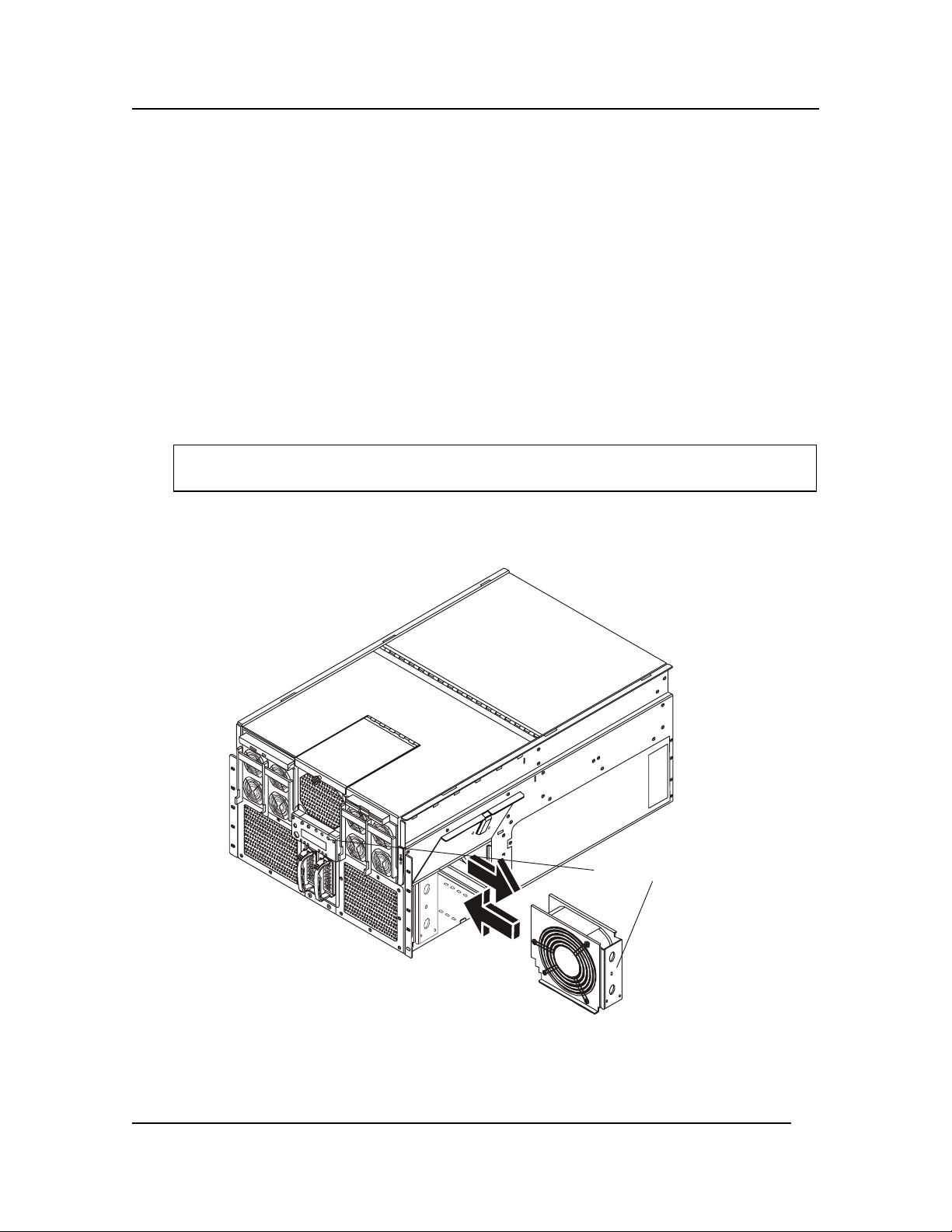
Chapter 3: Installing Fans and Power Supplies
Hot Swapping the 172 mm Fans
The four 172 mm cooling fans are mounted in pairs on each side of the chassis. You can hot-swap
these fans without turning the server system power off. Each fan uses an amber LED located on the
fan’s casing to indicate the fan has failed. If it is a failed fan, the amber LED will be illuminated on
the front panel, and the amber LED on the failed fan itself will be illuminated. The individual fan
LEDs may be seen through view-ports in the fan covers
Removing the 172 mm Fans
To remove the 172 mm fan, complete the following steps:
1. Observe all standard safety and ESD precautions.
2. Slide the server out of the rack far enough to expose the fan-access doors near the front sides
of the chassis.
CAUTION Do not leave the door open for an extended time. Cooling of the system could be
reduced.
3. Slide the plastic latch on the fan cover upwards and pull the door open.
4. Grasp the fan assembly with the finger holes and pull it out.
LED Indicator
Figure 3-1. Removing the 172 mm Fans
18
Page 26

Chapter 3: Installing Fans and Power Supplies
Installing the 172 mm Fans
To install the 172 mm fan, complete the following procedure:
1. Lift the latch on the fan-access door and open the door.
NOTE Verify the connector orientation prior to installing the new fan.
2. Slide the new fan into place with the connector oriented to engage the socket inside of the fan
enclosure.
3. Push the fan assembly firmly into the enclosure to seat the connector.
4. Close the fan-access door and engage the latch by pushing it downward.
5. Slide the chassis back into the rack.
Hot Swapping the 120 mm Fans
The two 120 mm cooling fans are mounted on the top front of the chassis. These fans can be replaced
without shutting down power to the system. If it is a failed fan, the amber LED will be illuminated on
the front panel, and the amber LED on the failed fan itself will be illuminated. The individual fan
LEDs may be seen through view-ports in the fan covers
Removing the 120 mm Fans
To remove the 120mm fan, complete the following procedure:
1. Slide the server out of the rack far enough to expose the fan-access door on the top of the
chassis.
2. Unscrew the thumbscrew on the front of the fan-access door and lift the door open. If a fan
has failed, the amber LED light is illuminated.
CAUTION Do not leave the door open for an extended time. Cooling of the system could be
reduced
3. Grasp the fan assembly through the finger holes and pull the assembly out.
19
Page 27

Chapter 3: Installing Fans and Power Supplies
Figure 3-2. Removing the 120 mm Fans
Installing the 120 mm Fans
Follow these steps to install a 120 mm fan:
1. Slide the server out of the rack far enough to expose the fan-access door on the top of the
chassis.
2. Unscrew the thumbscrew on the front of the fan-access door and lift the door open.
3. Slide the new fan into place, with the connector oriented to engage the socket inside of the fan
enclosure.
4. Push the fan assembly firmly into the enclosure to seat the connector.
5. Close the fan-access door and tighten the thumbscrew.
6. Slide the chassis back into the rack.
20
Page 28

Chapter 3: Installing Fans and Power Supplies
Hot Swapping Power Supplies
The power system contains four 800-watt autoranging power supplies. The third bay’s power supply
from the left as you face the chassis serves a redundancy function for the server’s power supply
requirements.
CAUTION Because of chassis airflow disruption, the power supply bay should not be vacant
for more than five minutes when server power is on. Exceeding the five-minute
limit might cause system cooling to fall below the minimum required level and
possibly cause damage to system components.
NOTE The server requires a minimum of three power supplies to operate. If you have
only three power supplies operational, they must occupy the first, second, and
fourth power supply bays as you face the chassis. Figure 3-3 shows the power
supply installation order.
2
4
3
1
If only 3 power supplies
are operational, place a
filler panel over the fourth
bay in the installation order.
Figure 3-3. Power Supply Installation Order
21
Page 29

Chapter 3: Installing Fans and Power Supplies
Determining Power Supply Status
When the amber power supply failure LED on the front of the chassis turns on, determine which
power supply is defective by checking the three status LEDs on each supply. Each power supply has
three LEDs that both indicate whether power is supplied to the power supply and the health of the
power supply. The LEDs are ordered top to bottom on each power supply. Table 3-1 illustrates the
states indicated by the three LEDs.
Table 3-1. Power Supply LEDs
Power Supply Status
PWR
(Green)
(Top
Position)
PFAIL
(Amber)
(Middle
Position)
FAIL
(Amber)
(Bottom
Position)
No AC power to any power supplies Off Off Off
No AC power to a specific power supply Off Off On
AC present / Standby output on Blinking Off Off
DC outputs on and okay On Off Off
Power supply failure Off Off On
Current limit On Off Blinking
Predictive failure On Blinking /
Off
Latched
22
Page 30

Chapter 3: Installing Fans and Power Supplies
Removing a Power Supply
To remove a power supply, complete the following procedure:
1. Locate the power supply you want to remove.
2. Push the thumb latch to unlock the power supply handle and pull the handle down to undock
the supply.
CAUTION Any unused power supply slots must be covered with a blanking plug. Uncovered
slots can disrupt the air flow used for cooling the system.
Figure 3-4. Removing a Power Supply
3. Pull the power supply straight forward, out of the chassis. Set it aside.
23
Page 31

Chapter 3: Installing Fans and Power Supplies
Installing a Power Supply
The power supply bay should not be vacant for more than five minutes when server power is on.
Disruption of the airflow may cause system cooling to fall below acceptable levels. To install the new
power supply, complete the following procedure:
1. Remove the new power supply from the protective packaging, and place it on an antistatic
surface.
2. Record the model and serial numbers of the power supply in your equipment log.
3. With the handle in the open position (pulled down), slide the replacement power supply into
the power supply bay until it stops.
4. Rotate the handle up and in to lock the power supply into place.
5. Check the new power supply LEDs to verify proper functioning.
24
Page 32

4 Installing Mass Storage Devices
Introduction
The HP Server comes standard with a DVD and a floppy diskette drive. The internal mass storage
cages support a maximum of two hot swap drive carriers. Each carrier can house a standard one inch
high by three and half inch wide SCSI-2 or SCSI-3 hard drive. The internal SCSI drives are mounted
to the carriers using four screws.
Mass Storage Guidelines
• General Guidelines
◊ Use care when unpacking and handling the SCSI disk drives.
The hard disk drives are very susceptible to mechanical shock and can be easily damaged
by a drop as short as one-quarter of an inch. If the drop would crack an egg, it will damage
the drive.
◊ Do not stack drives.
◊ The HP Server is internally limited to 2 SCSI disk drives
• IDE Devices
◊ The diskette drive and DVD drive are standard on all models of the HP Server. They are
housed in two piece drive carrier assemblies that rest on the chassis surface. They are
accessible when the top cover is removed. See Figures 4-3 and 4-4.
◊◊◊◊ The Legacy I/O board contains the PCI-enhanced IDE interface with two IDE buses. The
primary IDE 0 bus supports the diskette drive and the secondary IDE 1 bus supports the
DVD drive.
Refer to "System Board Layout" in Appendix A, "Specifications."
• SCSI Device Selection
◊◊◊◊ A Qlogic ISP12160A Ultra3 SCSI chip is a highly integrated bus master, dual-channel
SCSI I/O processor for SCSI initiator and target applications. The chip supports dual
channel, Ultra3 (160) SCSI functionality and is pin compatible with QLogic’s ISP12160
Ultra3 SCSI processor as well as QLogic’s ISP1280 dual SCSI processor.
◊◊◊◊ Use only low-voltage differential (LVD) SCSI devices.
Boot Priority
The HP Server's boot order should be considered when selecting a PCI slot on the system board. This
is especially important if you are installing a board that requires an early number in the boot order.
The board's boot priority is set by its slot location in the boot order.
By default the HP Server searches for boot devices in this order:
1. SCSI
2. PM
3. SM
25
Page 33

Chapter 4: Installing Mass Storage Devices
4. PS
5. Other Boot Devices
IDE DVD drive
Flexible disk drive
6. PCI slot 1
7. PCI slot 2
8. PCI slot 3
9. PCI slot 4
10. PCI slot 5
11. PCI slot 6
12. PCI slot 7
13. PCI slot 8
14. PCI slot 9
15. PCI slot 10
The SCSI controller chip interfaces the PCI bus to two Ultra3 SCSI buses and contains an onboard
RISC processor. The RISC processor is a fully autonomous device, capable of managing multiple I/O
operations and associated data transfers from start to finish without host intervention. It provides
power management feature support in accordance with the PCI Bus Power Management Interface
Specification.
NOTE The boot order can be changed using the Server's (BIOS) Setup Utility and the
Qlogic SCSI Utility. Refer to Chapter 10, "Configuring the HP Server" for more
information.
Tools Required
The following tools are required for the removal and installation of mass storage devices in the HP
Server:
• Phillips (cross-head) screwdriver (#2).
• Small flat-bladed screwdriver.
• Jumper-removal tool or needle-nosed pliers.
• Antistatic wrist strap and conductive foam pad (recommended).
• Pen or pencil.
• Equipment log: to record the model and serial numbers of components.
Installing a Hot Swap Hard Drive
The HP Server supports a variety of single-ended SCSI SCA-type hard disk drives. The area of the
chassis below the system’s controls and indicators on the front panel houses up to two 3.5-inch bays.
Each bay can contain a single industry-standard SCSI-2 or SCSI-3, one-inch high hard disk drive
26
Page 34

Chapter 4: Installing Mass Storage Devices
from the factory. The procedures in this section describe how to determine drive status, remove a
faulty drive, and install a new drive.
Determining Drive Status
Status LEDs arranged in sets of three over each of the two Hard Disk Bays monitor the status of each
drive.
Table 4-1. SCSI Drive Status LED Descriptions
SCSI drive present
with power on
Green LED
Left
On Off Off Drive is present with
On Blinking Off Drive is present with
Off Off On Steady amber fault light
On
Off Slow Blinking Drive SHOULD NOT be
Off
Off Off There is no drive installed
SCSI drive
active
Green LED
Middle
SCSI drive
faulty*
Amber LED
Right
Description and Action
(If Required)
power.
power and is being
accessed.
indicates drive has a
problem.
replaced at this time. A
slowly blinking amber
fault light indicates that a
drive that has just been
replaced is in recovery
mode (drive array being
rebuilt). Power to drive is
on.
in the bay.
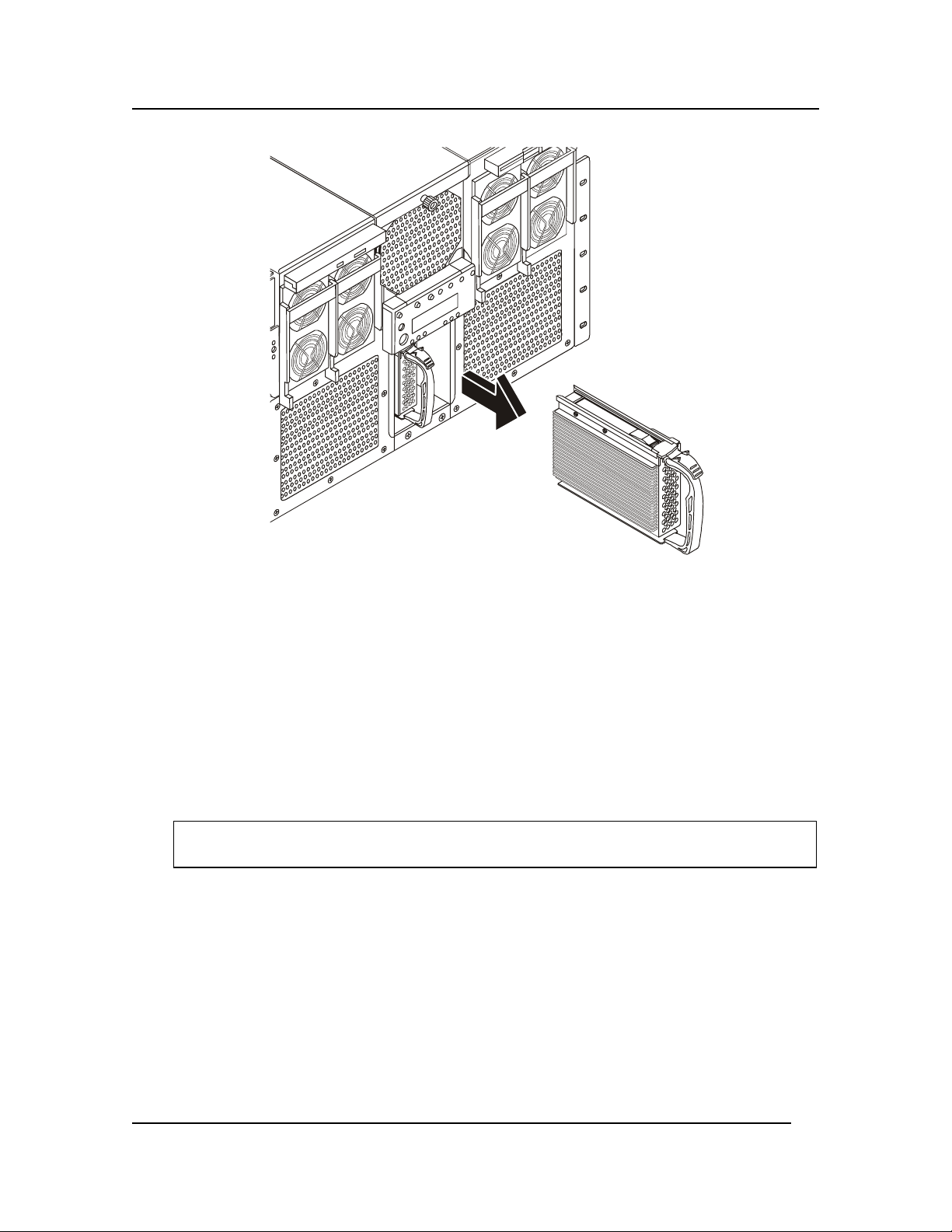
Removing a Hard Disk Drive
To remove a hard disk drive from the disk bay, complete the following procedure:
1. Look at the amber LEDs above the hard disk bays to determine which drive is bad. See Table
4-1 for information on how to interpret the LEDs.
2. Remove the plastic bezel on the front of the server.
3. Depress the drive carrier latch of the bad drive, and use the handle to pull the assembly toward
you to disengage the drive from the backplane connector.
27
Page 35
Chapter 4: Installing Mass Storage Devices
Figure 4-1. Removing a Hard Disk Drive
4. Carefully slide the assembly out of the bay, and place it on an antistatic surface.
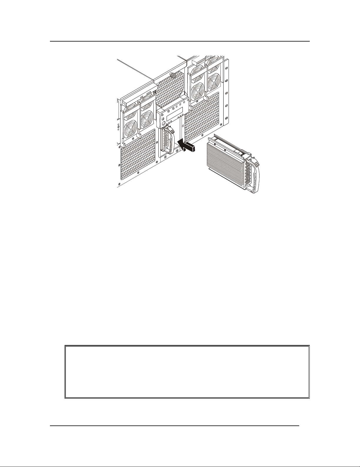
Installing a Hard Disk Drive
Hard disk drives are packaged in their drive carriers for immediate installation. They require no
assembly and may be installed without the use of any tools. To install the hard disk drive, complete
the following procedure:
1. Remove the plastic bezel on the front of the server.
2. Orient the new drive’s carrier and drive assembly in front of the bay guide rails so that the
latch is toward the top. Make sure that the carrier is placed correctly into the guide rails to
avoid damage.
CAUTION Do not press on the perforated metal bracket of the carrier when you push the
assembly into the bay, or you may damage the metal fingers of the bracket.
3. While grasping only the drive carrier handle, firmly push the assembly into the bay until the
drive docks with the backplane connector and the carrier latch locks.
28
Page 36
Chapter 4: Installing Mass Storage Devices
Figure 4-2 Hot Swapping a SCSI Drive
4. Replace the plastic bezel on the front of the server.
Installing Non-Hot Swap Drives
The HP Server supports a slimline IDE diskette drive for 1.44 MB and 120 MB media and a DVD
drive. Both drives are part of the standard configuration and mount directly above the power bays on
the front of the chassis. The drives are mounted on removable trays that facilitate system assembly
and service. The server must be powered down to install these drives.
Installing the Floppy Disk Drive
The floppy disk drive is housed in a two-piece drive carrier assembly that rests on the chassis surface.
The assembly is accessible when the top cover is removed. The following procedures describe how to
remove and install the drive.
Removing the Floppy Diskette Drive
To remove the floppy diskette drive, complete the following procedure:
1. Observe all safety and ESD precautions whenever you remove the cover from the HP Server.
WARNING Before removing the top cover, always disconnect the power cord and unplug the
Ethernet cables. Disconnect the power cord to avoid exposure to high energy
levels that may cause burns when parts are short-circuited by metal objects such
as tools or jewelry.
The power switch does NOT turn off the standby power. Disconnect the power
cord from the HP Server before handling components.
2. Remove the top cover as described in “Removing and Replacing the HP Server’s Main Cover”
in Chapter 2.
29
Page 37
Chapter 4: Installing Mass Storage Devices
3. Disconnect the drive’s data and power cables from cable adapter PCB at the rear of the drive.
4. Loosen the thumbscrew found at the rear of the drive carrier assembly.
5. Slide the drive and the drive carrier assembly toward the rear of the chassis so that the front
part of the drive clears the opening in the chassis.
6. Remove the drive carrier assembly with the drive in it from the chassis.
7. Place the drive in an antistatic protective wrapper if you are not reinstalling the same drive.
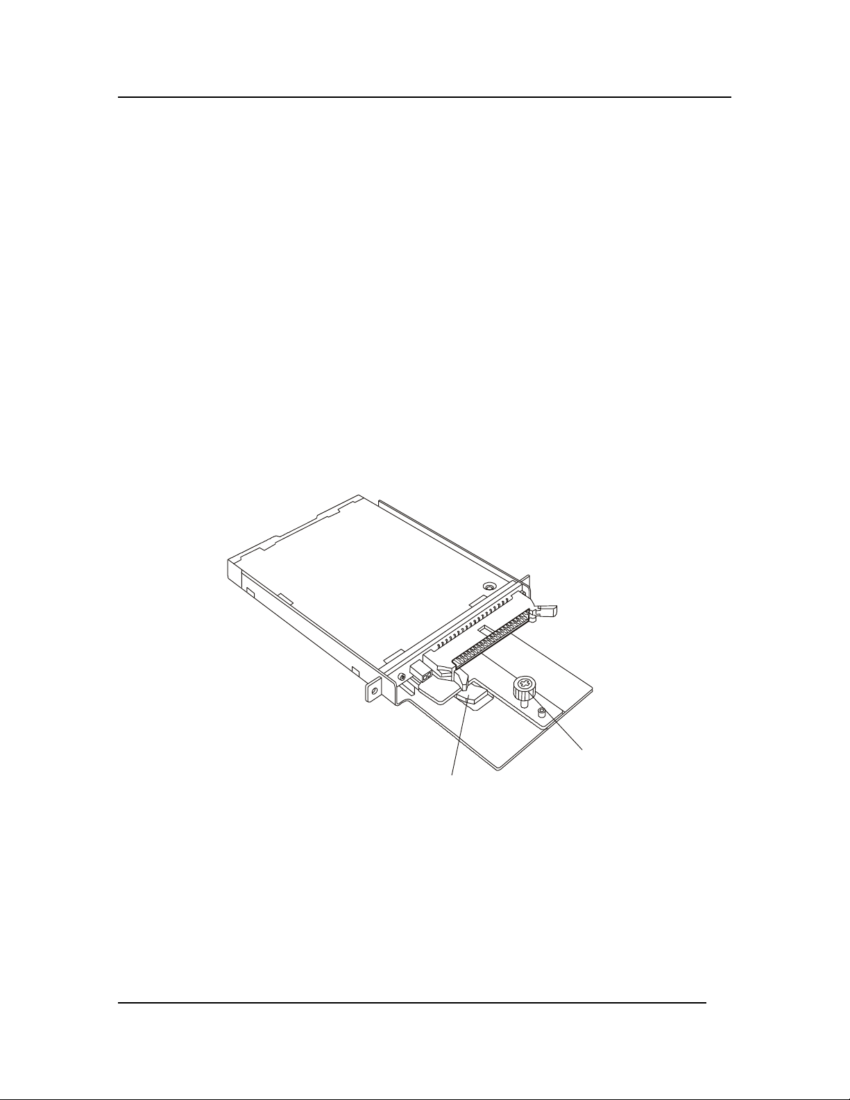
Installing the Floppy Disk Drive
To install the new floppy diskette drive, complete the following steps:
1. Remove the new drive assembly from its protective wrapper, and place it component-side up
on an antistatic surface.
2. Record the drive model and serial numbers in your equipment log.
3. Pick up the entire drive carrier assembly, being careful that you keep the pieces together, and
place it on the chassis surface just inside the drive slot.
4. Grasp the sides of the drive and drive carrier assembly and slide it forward such that the front
part of the drive comes through the opening in the chassis. Make sure that the thumbscrew at
the rear of the drive carrier assembly aligns with the hole in the surface of the chassis.
Thumbscrew
Tab
Figure 4-3. Diskette Drive
5. Tighten the thumbscrew at the rear of the drive carrier assembly.
6. Install the drive’s data and power cables into the cable adapter PCB.
7. Install the top cover.
Installing the DVD Drive
The DVD Drive is housed in two-piece drive carrier assembly that rests on the chassis surface. The
drive carrier assembly is accessible when the top cover is removed. The following sections describe
how to remove and install the drive.
30
Page 38
Chapter 4: Installing Mass Storage Devices
Removing the DVD Drive
To remove the DVD drive, complete the following procedure:
1. Observe the safety and ESD precautions at the beginning of this chapter.
2. Remove the top cover as described in “Removing and Replacing the HP Server’s Main Cover”
in Chapter 2.
3. Disconnect the drive’s data and power cables from the drive cable adapter PCB at the rear of
the drive.
4. Loosen the thumbscrew found at the rear of the drive carrier assembly.
5. Slide the drive and drive carrier assembly towards the rear of the chassis so that the front part
of the drive clears the opening in the chassis.
6. Place the drive in an antistatic protective wrapper if you are not reinstalling the same drive.
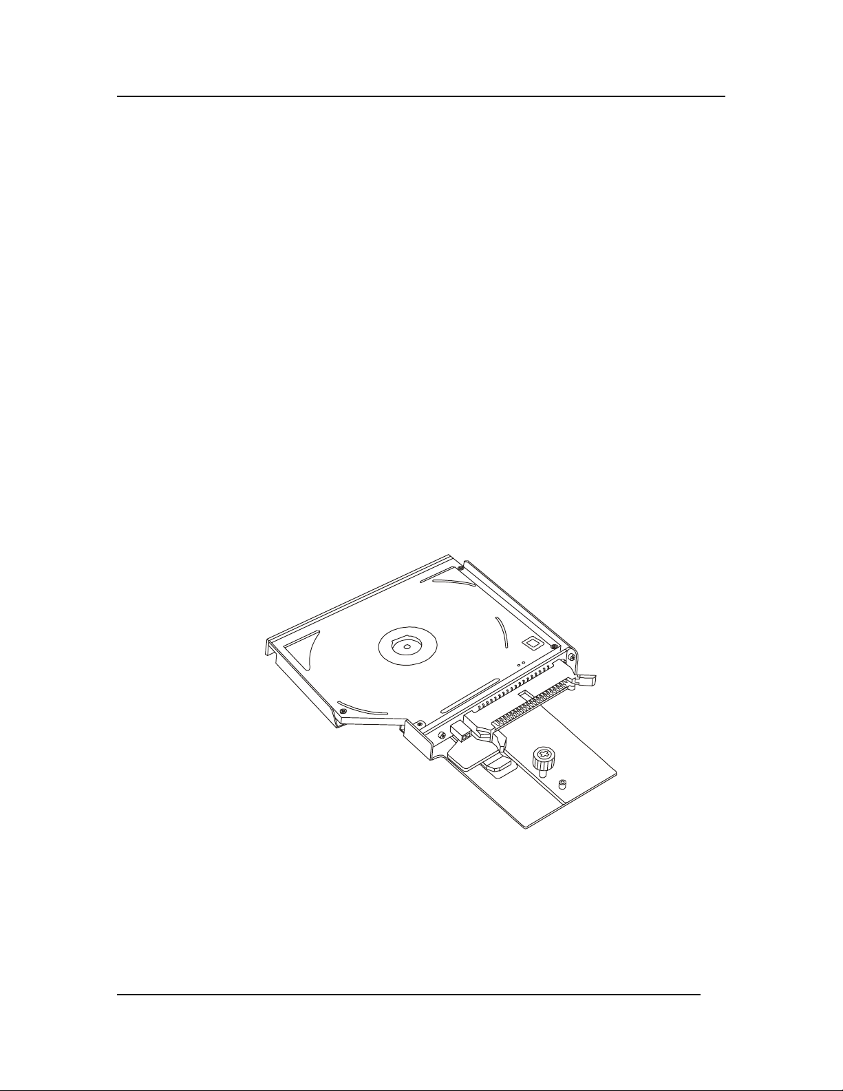
Installing the DVD Drive
To install the new DVD drive, complete the following steps:
1. Remove the new drive from its protective wrapper, and place it face down on an antistatic
surface.
2. Record the drive model and serial numbers in your equipment log.
3. Pick up the DVD drive and drive carrier assembly and place it face up (carrier side down) on
the chassis such that the front of the drive is aligned with the opening in the front of the
chassis.
Figure 4-4. Installing the DVD
4. Grasp the sides of the drive and drive carrier assembly and slide it forward such that the front
part of the drive comes through the opening in the chassis. Make sure that the thumbscrew at
the rear of the drive carrier assembly aligns with the hole in the surface of the chassis.
5. Tighten the thumbscrew at the rear of the drive carrier assembly.
6. Connect the drive’s data and power cables.
31
Page 39

Chapter 4: Installing Mass Storage Devices
7. Install the top cover as described in “Removing and Replacing the HP Server’s Main Cover” in
Chapter 2.
Connecting External SCSI Devices
The second SCSI channel B is connected directly to the external VHD (Very High Density) 68-pin
SCSI connector on the rear panel. All external SCSI devices are connected to the HP Server using this
external connector, but the external SCSI devices must provide the necessary termination at the end of
the SCSI chain. If no external devices are connected, then no termination is required. The internal
SCSI controller terminates channel B electrically, if no external devices are sensed at the connector.
Please consult the product update information for the latest approved adapters on the following HP
website:
http://www.hp.com
Removing and Installing the Hard Disk Bay
The Hard Drive Bay provides mounting features for two hot swap hard drives, the Front Panel
Interface board, and the Hot Swap Backplane board. You can easily remove and install the bay from
the chassis by removing the front bezel and four mounting screws.
Removing the Hard Disk Bay
To remove the Hard Disk Bay, complete the following procedure:
1. Turn off the system by using the power on/off switch on the front of the chassis and remove
both AC power cords.
2. Remove the front bezel.
3. Remove each hard disk drive from the drive bay by first grasping its handle and depressing the
drive locking tab, and then sliding the drive out of the bay.
4. Remove the four #2 Phillips screws from the top and bottom of the drive bay.
5. Grasp the bay by the Front Panel display housing and gently pull the drive bay out of the
chassis.
Figure 4-5. Hard Disk Bay
32
Page 40

Chapter 4: Installing Mass Storage Devices
Installing the Hard Disk Bay
To install the Hard Disk Bay, complete the following steps:
1. Turn off the system by using the power on/off switch on the front of the chassis and remove
both AC power cords.
2. If the front bezel is not already removed, remove the bezel.
3. Align the Hard Disk Bay such that the connector side is facing into the chassis and push the
bay into the front of the chassis.
4. Ensure the drive bay seats into the front connector on the Power Distribution Board (TDocking Board).
5. Replace the four screws at the top and bottom of the bay.
6. Replace any disk drives into drive bay as required.
7. Replace the Front Bezel.
33
Page 41

Chapter 4: Installing Mass Storage Devices
Removing and Installing the SCSI Backplane
The SCSI Backplane resides on the back of the Hard Drive Bay. It is accessed by removing the Hard
Disk Bay.
Removing the SCSI Backplane
To remove the SCSI Backplane, complete the following steps:
1. Remove the Hard Disk Bay as described in “Removing the Hard Disk Bay” earlier in this
chapter.
2. Disconnect the LCD panel cable from the SCSI Backplane.
3. Remove the cap stabilizer retaining screw and the cap stabilizer. These two items will be used
on the new board.
4. Remove the three screws that secure the SCSI Backplane to the Hard Disk Bay.
5. Carefully place the SCSI Backplane on a clean, anti-static work surface or in anti-static
packaging.
Figure 4-6. Removing the SCSI Backplane
Installing the SCSI Backplane Board
To install the SCSI Backplane Board, complete the following procedure:
1. Carefully align the SCSI Backplane in the slots to the rear of the Hard Disk Bay. Be sure that
the four holes in the SCSI Backplane align with the holes and alignment pin in the bay.
2. Secure the SCSI Backplane to the bay by tightening the three screws.
3. Connect the Front Panel cable to the SCSI Backplane. Open the cable connector lock tabs to a
4. Position the cap stabilizer and secure it with the cap stabilizer retaining screw.
5. Install the Hard Drive Bay as described in “Installing the Bay” earlier in this chapter.
c
45
angle before inserting the cable.
34
Page 42

Chapter 4: Installing Mass Storage Devices
Installing the Front Panel Board
The Front Panel Board displays server information. The module is attached to the front of the Hard
Disk Bay, which must first be removed to gain access to the Front Panel Board.
Removing the Front Panel Module
To remove the Front Panel module, complete the following procedure:
1. Turn off the system by using the power on/off switch on the front of the chassis and remove
both AC power cords.
2. Remove the Hard Disk Bay from the chassis as described in “Removing the Hard Disk Bay”
earlier in this chapter.
3. Disconnect the cable to the Front Panel Board that is attached to the front of the Hard Disk Bay
by squeezing the cable retention levers together. You do not have to remove the rear part of
the cable.
4. Remove the two screws securing the Front Panel Board to the front panel mounting on the
Hard Disk Bay. These screws are located on the inside of the Front Panel Board.
5. Remove the Front Panel Board from the Hard Disk Bay assembly and place it on an ESD
protected work surface.
2. Remove the two screws.
Figure 4-7 The Front Panel Board
1. Disconnect the cable.
Installing the Front Panel Board
To install the new Front Panel Board, complete the following steps:
1. Using two Phillips screws, secure the new Front Panel Board to the Hard Disk Bay.
2. Connect the front part of the Front Panel Board data cable to the connector on the new Front
Panel Board.
3. Install the Hard Disk Bay into the chassis as described in “Installing the Hard Disk Bay”
above.
35
Page 43

5 Installing Additional Memory
Introduction
This chapter provides the procedures for opening the Processor/Memory Complex, installing a
memory board, installing DIMMs, and installing memory board DC-to-DC converters.
Tools Required
Use an anti-static service kit (3M 8501/8502/8503 or equivalent). This kit includes a static-dissipating
work surface, a chassis clip lead, and a wrist strap.
Memory Installation Guidelines
Each Memory Board can support from 1 GB to 32 GB. The server supports up to 64 GB of system
memory.
• Use only HP DIMMs, which are 3.3V, 168-pin, PC100, buffered SDRAM DIMMs in 256 MB,
512 MB, or 1 GB modules.
• DIMMs must be installed in the order indicated by the numbered slots on the memory board in
groups of four. Verify that the same size DIMM is used in any given group of four by using
the same HP part number.
• To ensure optimum performance when two memory boards are installed, the memory on each
board should be equal.
• Ensure both latches close on the DIMM when completely installed.
• When handling DIMMs, observe anti-static precautions to avoid damage.
36
Page 44

Chapter 5: Installing Additional Memory
Removing the Processor/Memory Complex
The Processor/Memory Complex mounts memory boards to the processor board and forms a module
that you can remove from the main system chassis. To access this module, you need to remove the
access door on the side of the chassis and remove the four screws on the left side of the chassis to
slide the Processor/Memory Complex out of the system.
1. If the system is already installed and working, power down the system. Refer to Chapter 1,
"Controls, Ports, and Indicators."
WARNING The power supply will continue to provide standby current to the HP Server until
the power cable is disconnected. Before removing the cover, always disconnect
the power cord and unplug the Ethernet cables. Disconnect the power cord to
avoid exposure to high energy levels that may cause burns when parts are shortcircuited by metal objects such as tools or jewelry.
2. Disconnect the power cables and any external cables connected to the system.
If necessary, label each cable to expedite re-assembly.
WARNING Make sure that the rack is anchored securely so that it does not tip when the server
is extended from the rack.
3. Pull the chassis out of the rack to expose the Processor/Memory Bay on the right side of the
chassis as you face its front.
4. Remove the four screws that secure the complex to the chassis. These screws are located on
the left side of the chassis as you face the front of the system.
5. Loosen the two-quarter turn screws on the left side of the Processor/Memory Complex cover
such that the cover springs open.
6. Grasp the cover and press it back toward the chassis as you shift the cover to the left. Shifting
the cover to the left clears the right side of the cover from behind the chassis side.
3
Figure 5-1. Opening the Processor/Memory Complex Bay Cover
7. Once the cover is clear, set it aside.
37
Page 45

Chapter 5: Installing Additional Memory
8. Rotate the two extraction levers on the sides of the module to eject it from the Sideplane board
connector.
Figure 5-2. Removing the Processor/Memory Complex
WARNING Fully loaded, the Processor/Memory Complex weighs 36 pounds (16.33 kg).
Minimally configured, this complex weighs 24 pounds (10.80 kg). Exercise
caution when lifting the complex out of the system.
9. Remove the complex from the bay and place it on a clean ESD protected surface.
Removing the Memory Board DC-to-DC Converters
The Memory Board DC-DC Converters reside on the side of the Processor/Memory Complex inside
the system chassis. The server uses four converters to supply regulated power to the system. You can
access them by removing the Processor/Memory Complex and working from its side. The Memory
Board DC-to-DC Converters must be removed before the Memory Board can be replaced.
To remove the converters, complete the following procedure:
1. Observe the necessary safety and ESD precautions.
2. Remove the Processor/Memory Complex as described in “Removing the Processor/Memory
Complex” in Chapter 5.
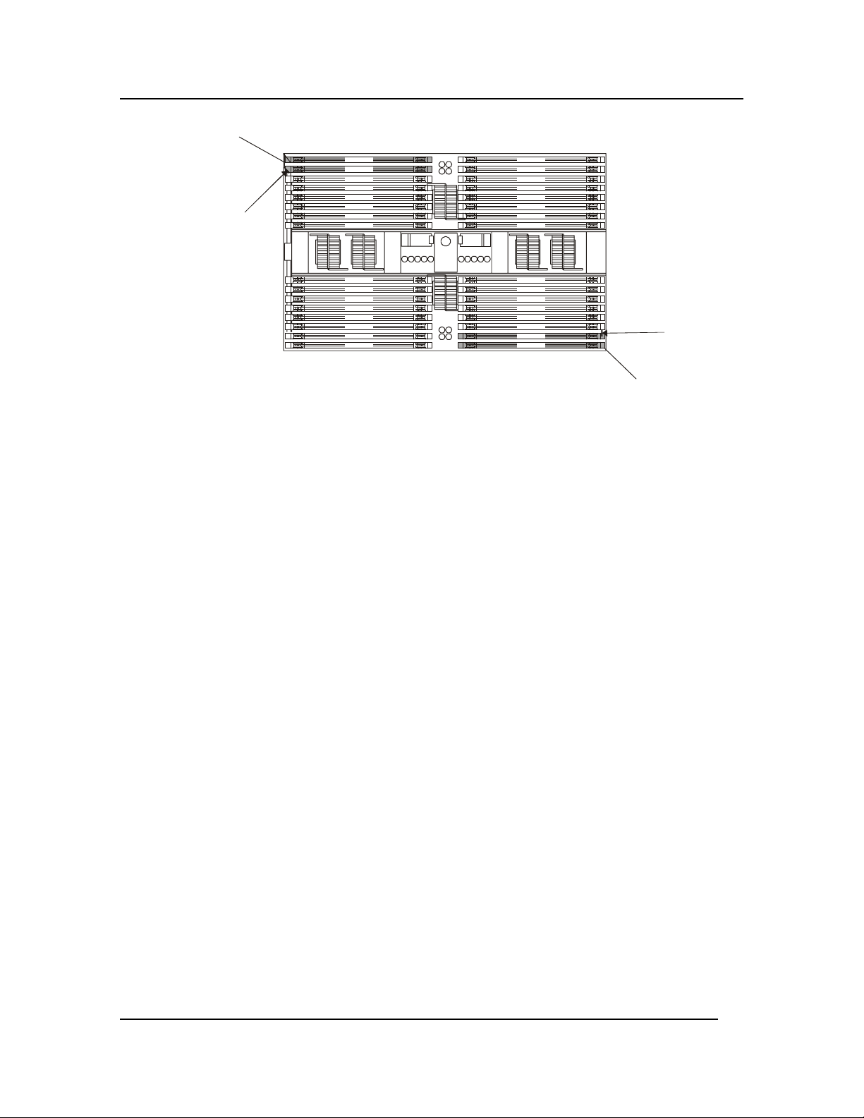
3. Loosen the slide clamp screw that secures the converters but do not remove it. Loosening the
upper screw allows you to remove the upper converters, while loosing the lower screw allows
you to remove the lower converters.
4. With the converters to be removed located on the top of the unit, slide the clamp upward that
secures that pair of converters.
5. Pull each converter straight out from its socket. Be sure that you keep the converter level as
you remove it from its socket. Each converter has a keyed guide that is attached to the side of
the Processor/Memory Complex.
38
Page 46

Chapter 5: Installing Additional Memory
Figure 5-3. Memory Board DC-DC Converters
Removing and Installing Memory Boards
Two Memory Boards reside in the Processor/Memory Complex: one is on top of the complex and the
other underneath. You can remove or install these memory boards.
Removing Memory Boards
Two memory boards exist, one plugged in to each side of the processor board (the top and the
underside of the Processor/Memory Complex). The following procedure describes the removal
process for either memory board. To remove the memory board, complete the following procedure:
1. Open and remove the Processor/Memory Complex.
2. If desired, remove the DIMMs from the memory board you are removing as described in
“Removing DIMMs” in Chapter 5.
3. Remove the DC-DC converters from the memory board as described in “Removing the
Memory Board DC-DC Converters” in Chapter 5.
4. Loosen the two captive screws holding the sides of the memory board to the processor board.
Each of these screws secures a board clamp that runs along the length of the memory board.
5. Lift the board clamps out of the Processor/Memory Complex.
6. Loosen the two captive screws at the end of the handle that spans the middle of the Memory
Board.
7. Remove the bracket with the thumbscrew that locks the extraction levers.
8. Pull up on the extraction levers to disengage the memory board from the processor board.
NOTE Both extraction levers must be raised evenly while disengaging the memory from
the Processor Baseboard. The memory board must remain parallel to the Processor
Baseboard during extraction.
39
Page 47

Chapter 5: Installing Additional Memory
9. Place the memory board on a clean ESD-protected surface.
Figure 5-4. Memory Boards
Installing Memory Boards
Two memory boards exist, one plugged into each side of the Processor Baseboard (the top and the
underside of the Processor/Memory Complex). This procedure describes the installation process for
either memory board. To re-install the memory board or install a new board, complete the following
procedure:
1. Observe all safety and ESD precautions.
2. Remove the Processor/Memory Complex as described in “Removing the Processor/Memory
Complex” in Chapter 5.
3. With both extraction levers raised to engage the guide pins, place the memory board over the
Processor Baseboard connector and guide pins
4. Engage both guide pins at the same time. Ensure that the memory board remains parallel to
the Processor Baseboard.
NOTE Both extraction levers must be depressed evenly while inserting the Memory
Board. The Memory Board must remain parallel to the Processor Baseboard
during insertion.
5. Slowly depress the levers until the Memory Board connector fully engages.
40
Page 48

Chapter 5: Installing Additional Memory
6. Tighten the two captive screws at the end of the extraction handle.
7. Place the two board clamps along the sides of the memory board such that the screws align
with their respective holes.
8. Secure the two board clamps with the two board clamp screws.
9. Place the bracket with the thumbscrew that locks the extraction lever over the extraction levers
and tighten the screw.
10. Replace the DC-DC converters as described in “Installing the Memory Board DC-to-DC
Converters” in Chapter 5.
11. If you removed any DIMMs replace them as described in “Installing DIMMs” in Chapter 5.
Replace the Processor/Memory Complex as described in “Installing the Processor/Memory
Complex” in Chapter 5.
41
Page 49
Chapter 5: Installing Additional Memory
Installing and Removing DIMMs
The BIOS automatically detects, sizes, and initializes the memory array, depending on the type, size,
and speed of the installed DIMMs. It reports the memory size and allocation to the system through the
configuration registers. DIMMs reside in the Processor/Memory Complex and are accessible inside
the server chassis. To remove or install DIMMs you need to access the complex and follow the
installation order and groupings required for the DIMMs. It is not necessary to remove the memory
board from the complex.
Installing DIMMs
Please refer to the “Memory Installation Guidelines” earlier in this chapter before installing the
DIMMs. To install DIMMs, complete the following procedure:
CAUTION The memory modules are sensitive to static electricity and can be easily damaged
by improper handling. Do the following when handling the accessory kit:
• Leave the memory module in the anti-static container until you are ready to
install it.
• Always use an anti-static wrist strap and a grounding mat.
• Before you remove a memory module from the anti-static container, touch a
grounded, unpainted metal surface on the HP Server to discharge static
electricity.
1. If the system is already installed and working, power down the system.
Refer to Chapter 1, "Controls, Ports, and Indicators."
WARNING The power supply will continue to provide standby current to the HP Server until
the power cable is disconnected. Disconnect all power cables before servicing.
2. Disconnect the power cables and all external cables.
If necessary, label each one to aid in the re-assembly of the unit.
3. Remove the top cover from the HP Server.
Refer to Chapter 2, "Opening and Closing the HP Server."
4. Observe safety and ESD precautions when working with DIMMs.
5. Expose the memory boards by removing the Processor/Memory complex as described in
“Removing the Processor/Memory Complex” in Chapter 5.
CAUTION DIMM slots on the memory module must be installed only in groups of four.. The
number next to each DIMM slot corresponds to installation sequence. DIMMs
must be installed by groups of four and must be inserted in the indicated sequence
indicated on the memory board.
Remove the DIMM from its antistatic package. Align the two notches in the bottom edge of the
DIMM with the keyed socket on the memory board.
42
Page 50
Chapter 5: Installing Additional Memory
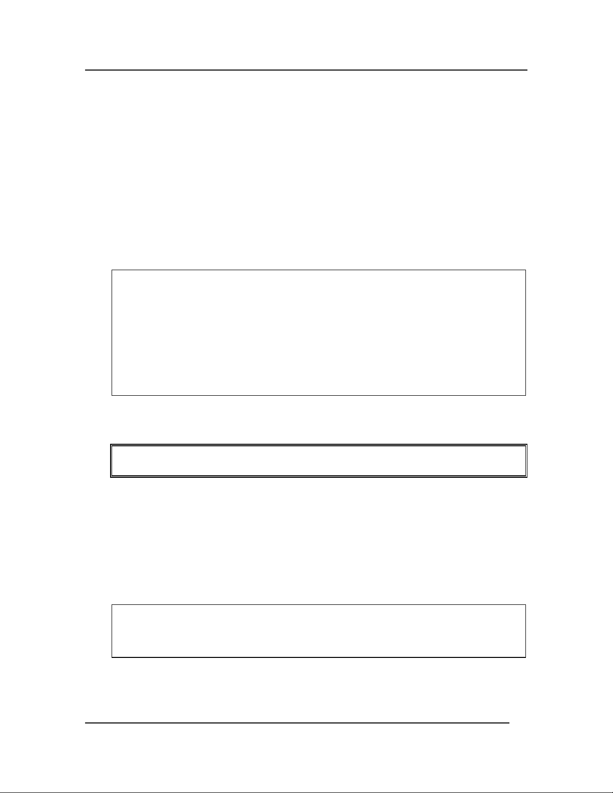
1
2
DIMM 1
DIMM 2
DIMM 9
DIMM 10
DIMM 17
DIMM 18
DIMM 25
DIMM 26
DIMM 5
DIMM 6
DIMM 13
DIMM 14
DIMM 21
DIMM 22
DIMM 29
DIMM 30
DIMM 32
DIMM 31
DIMM 24
DIMM 23
DIMM 16
DIMM 15
DIMM 8
DIMM 7
DIMM 28
DIMM 27
DIMM 20
DIMM 19
DIMM 12
DIMM 11
DIMM 4
DIMM 3
4
3
Figure 5-5. DIMM Installation Sequence
7. Insert the bottom edge of the DIMM into the socket and press down firmly until the DIMM is
seated correctly.
8. Push the plastic ejector levers on the socket ends to the upright position. Repeat the DIMM
installation steps for each DIMM you wish to install.
43
Page 51

Chapter 5: Installing Additional Memory
Removing DIMMs
You may need to remove a DIMM module to downsize your memory configuration or to replace a
defective DIMM.
1. If the system is already installed and working, power down the system.
Refer to Chapter 1, "Controls, Ports, and Indicators."
WARNING The power supply will continue to provide standby current to the HP Server until
the power cable is disconnected.
2. Disconnect the power cables and all external cables.
If necessary, label each one to support re-assembly.
3. Remove the top cover from the HP Server.
Refer to Chapter 2, "Opening and Closing the HP Server."
4. Remove the existing DIMM from its socket by gently pushing the plastic ejector levers out and
down.
5. Hold the DIMM only by its upper edges, being careful not to touch its components or gold
edge connectors. Carefully lift it away from the socket
6. Place the DIMM in its anti-static container.
Installing the Memory Board DC-to-DC Converters
The Memory Board DC-DC converters reside on the side of the Processor/Memory Complex inside
the system chassis. The server uses four converters to supply regulated power to the
Processor/Memory Complex. You can access them by removing the Processor/Memory Complex and
working from its side. The Memory Board DC-to-DC Converters must be installed after the Memory
Board is replaced. To install the converters, complete the following procedure:
1. Observe the necessary safety and ESD precautions.
2. Remove the Processor/Memory Complex as described in “Removing the Processor/Memory
Complex” in Chapter 5.
3. Carefully align the Processor DC-to-DC converter’s plug with the socket on the
Processor/Memory Complex assembly and press it firmly into place. Be sure to keep the
converter level such that the keyed guide accepts the edges of the bottom PCB on the
converter.
4. Slip the slide clamp up over the converter to secure it in place. Do not tighten the screws until
both pairs of converters have been installed.
5. Repeat steps three and four for each DC-to-DC converter you install. If you need to replace
converters on the secondary memory board beneath the complex, turn the complex over and
then replace the converters.
6. Reinstall the Processor/Memory Complex as described in “Installing the Processor/Memory
Complex” in Chapter 5.
44
Page 52
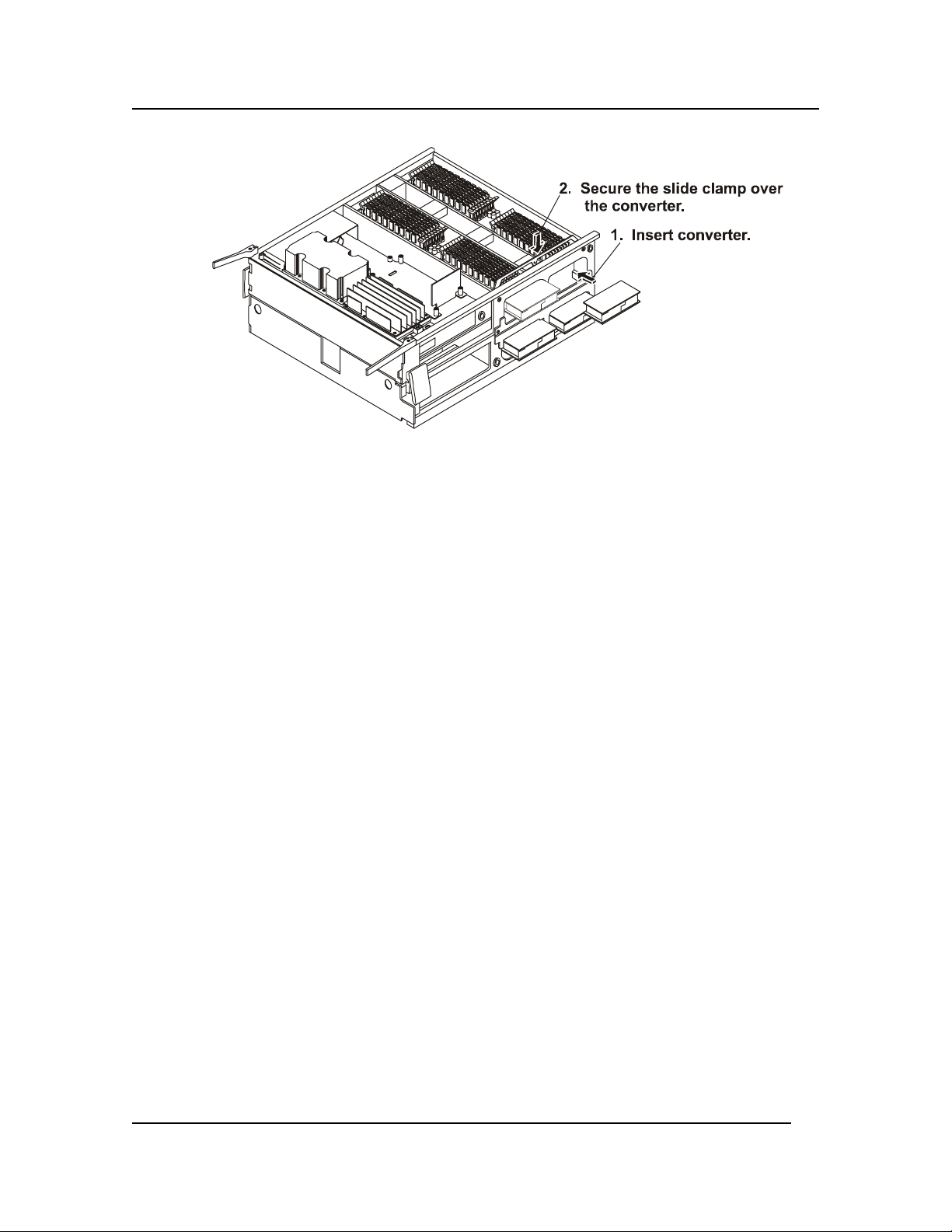
Chapter 5: Installing Additional Memory
Figure 5-6. Memory Board DC-to-DC Converters
Installing the Processor/Memory Complex
To replace the Processor/Memory Complex, complete the following procedure:
1. Orient the Processor/Memory Complex so that the high density connector is positioned to slide
into the Processor/Memory Bay and connect to the Sideplane board.
2. With the two extraction levers on the top and pointed towards you, slide the Complex into the
bay.
3. Push the extraction levers toward the chassis so that they are engaged at the same time, seating
the Complex into the Sideplane board.
4. Fasten the four screws on the left side of the chassis to hold the Processor/Memory Complex in
place.
5. Locate the Processor/Memory Complex Cover and orient it such that the right side of the cover
is just to the left of the right side of the bay.
6. Press the cover’s edge past the chassis and slide the cover to the right such that the edge of the
cover slips in behind the chassis frame.
7. Press the left side of the cover toward the chassis and secure the two screws at the left of the
cover.
8. Slide the unit into the rack.
45
Page 53

Chapter 6: Installing an Additional Processor
6 Installing an Additional Processor
Introduction
Each processor is packaged in a Slot M pin array cartridge. Depending on the configuration, your
system has two to four processors. Each processor is powered by a 48V power pod, located adjacent
to the processor on the processor board. Attached to the top of each processor is a heat sink that
dissipates thermal energy. CPU thermal dummies must be installed where a processor is absent to
properly direct cooling airflow.
Tools Required
The following tools are required to access and install or remove the processors:
• Phillips screwdriver (cross-head with #2 bit)
• Jumper removal tool or needle-nosed pliers
• An anti-static service kit (3M 8501/8502/8503 or equivalent). This kit includes a static-
dissipating work surface, a chassis clip lead, and a wrist strap.
• Equipment Log
Processor Configuration Guidelines
The HP Server supports a variety of processor speeds with an FSB (front side bus) speed of 133 MHz.
The HP Server supports processor speeds of 733 MHz and
800 MHz.
CAUTION Do not open the new processor's protective bag or remove it from the bag until
you are ready to install it.
Before you remove a processor from the anti-static container, touch a grounded,
unpainted metal surface on the HP Server to discharge static electricity.
• Both processors must be the same processor type and have the same product number, which
insures the same clock speed, cache size, and FSB speed.
• The processors must operate at the designated speed stated by the product type on the
processor.
• If the server has two processors, they must reside on the top half of the Processor/Memory
Complex.
z Use only processor upgrade kits with the same HP product number.
This ensures the processor type, clock speed, and cache sizes are the same.
46
Page 54
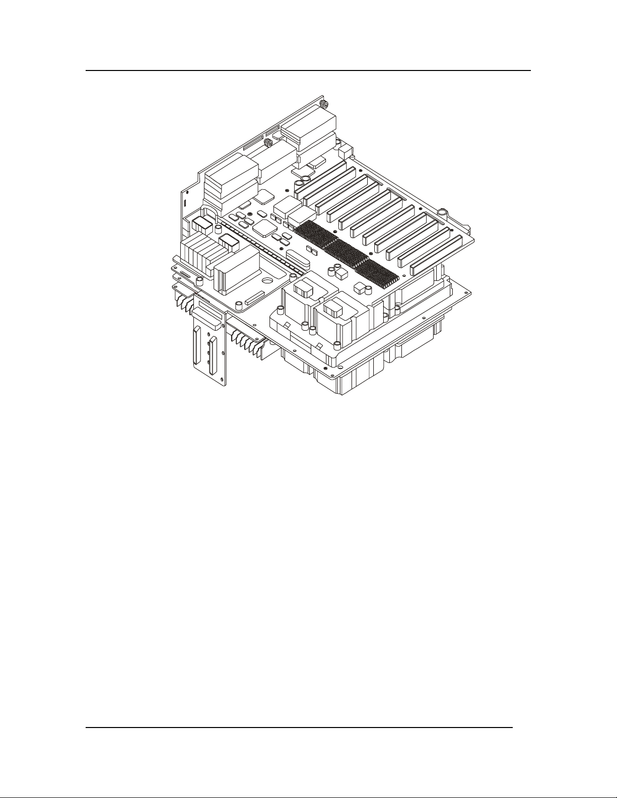
Chapter 6: Installing an Additional Processor
Figure 6-1. System Board Set
Removing the CPU Thermal Dummy
CPU thermal dummies must be installed where a processor is absent to properly direct cooling
airflow. Therefore, the CPU thermal dummy must be removed before installing an additional
processor.
Complete the following procedure to remove the CPU thermal dummy:
1. Observe the safety and ESD precautions at the beginning of this chapter.
2. Remove the Processor/Memory Complex as described in “Removing the Processor/Memory
Complex” in Chapter 5.
3. Orient the complex such that you have access to the surface from which you are removing
processors or CPU thermal dummies.
4. Loosen the four captive screws that secure the triple-beam to the sides of the
Processor/Memory Complex.
5. Remove the sheet metal baffle located to the front of the processors or CPU thermal dummies
in the Processor/Memory Complex. To remove the baffle, press the flexible retaining tabs in
as you slide the baffle out. You need this sheet metal baffle out of the way to access some of
the captive screws in the next step.
6. Loosen the captive screws in the top of the triple-beam and lift it up and away from the
Processor/Memory Complex.
7. Lift the blanks out of the complex.
47
Page 55

Chapter 6: Installing an Additional Processor
Installing an Additional Processor
This section provides the instructions for installing an additional processor. If only two processors are
to reside in the server, both processors must reside on the top half of the Processor/Memory Complex.
CAUTION The processor is sensitive to static electricity and can be easily damaged by
improper handling. Do the following when handling the accessory kit:
• Leave the processor in the anti-static container until you are ready to install it.
• Wear an anti-static wrist strap and use a static-dissipating work surface or
grounding mat connected to the chassis when handling components.
• Before you remove a processor from the anti-static container, touch a
grounded, unpainted metal surface on the HP Server to discharge static
electricity.
Complete the following steps to install an additional processor:
1. Unpack the processor shipping box and check the contents against its packing list.
2. If the HP Server is already installed and operating, shut down the NOS according to directions
in your NOS documentation.
3. Press the power switch on the HP Server's control panel when prompted by the operating
system. Normally, this completes the shutdown procedure.
WARNING Power supplies will continue to provide standby current to the HP Server until the
power cables are disconnected.
4. Disconnect the AC power cords.
WARNING Make sure that the rack is anchored securely, so it will not tip when the server
chassis is extended.
5. Pull the chassis out of the rack.
6. Remove the Processor/Memory Complex.
Refer to Chapter 5, "Removing the Processor/Memory Complex."
7. Ensure the processor speed of the second processor (CPU 2) is the same as the existing
processor before installing the second processor.
8. Make sure that the metal ejector pin in the processor socket is flush in the socket.
9. Position the microprocessor inside the four posts on the Processor Baseboard, pins toward the
rear and over the processor socket. Gently press the processor into position.
48
Page 56
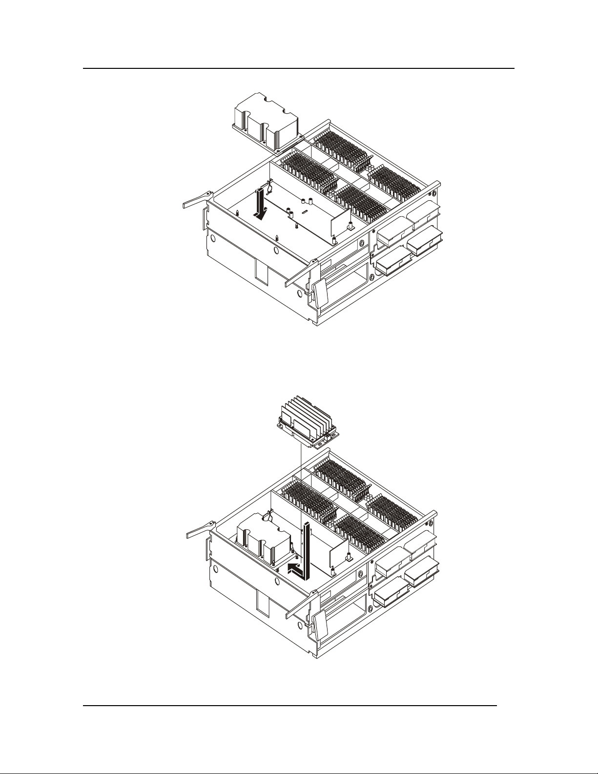
Chapter 6: Installing an Additional Processor
Figure 6-2. Installing the Microprocessor
10. Place the power pod into position on the Processor Baseboard. Ensure that the engaging tab is
to the rear of the retention module (RM) and then slide it forward to engage its connector on
the processor.
Figure 6-3. Connecting the Power Pod
49
Page 57
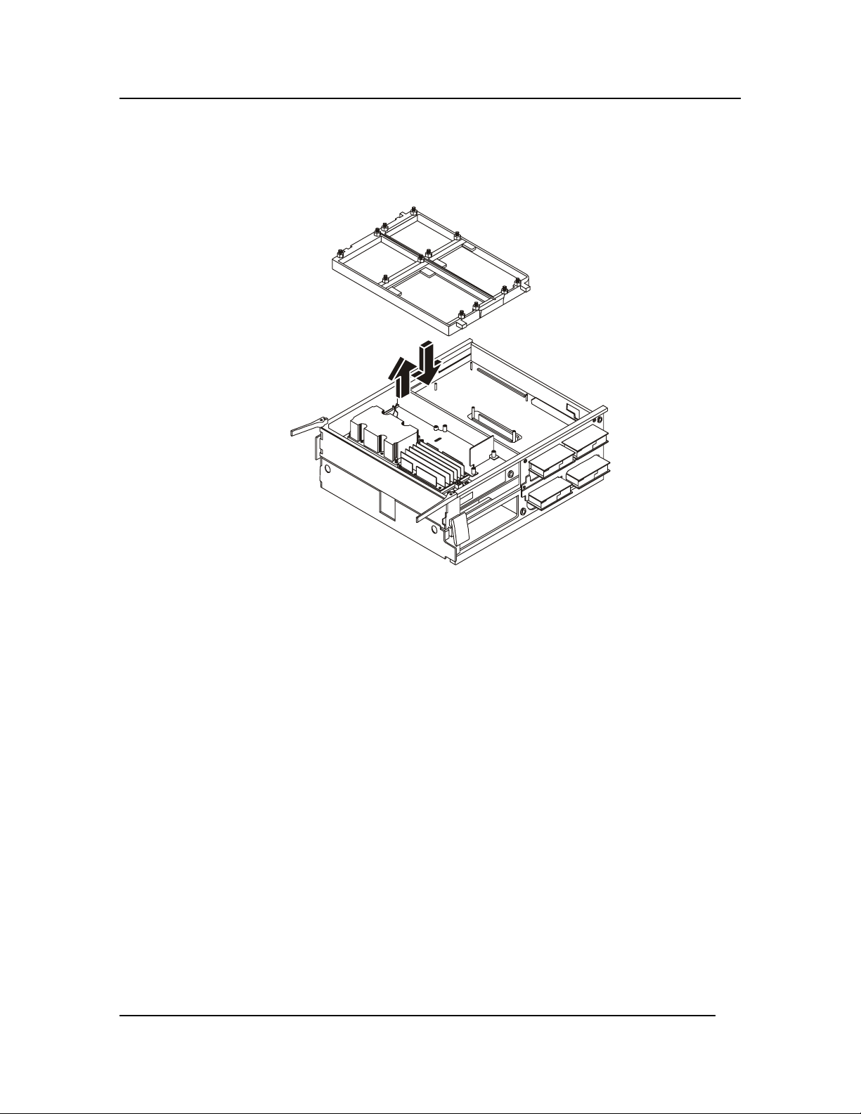
Chapter 6: Installing an Additional Processor
11. Place the triple beam into position by lowering it down over the processors/power pod or the
CPU thermal dummy.
12. Connect the Y-cable to each power pod.
Figure 6-4. Placing the Triple Beam Over the Processors
13. Secure the triple beam into place by tightening the top captive screws and then the four
thumbscrews on the end of the beam.
14. Insert the sheet metal baffle at the front of the processors or CPU thermal dummies in the
Processor/Memory Complex. To insert the baffle, press the flexible retaining tabs in as you
slide the baffle into place.
15. Be sure to close the plastic latch to secure the Processor/Memory Complex halves.
16. Insert the Processor/Memory Complex into the chassis as described in “Installing the
Processor/Memory Complex” in Chapter 5.
50
Page 58

Chapter 6: Installing an Additional Processor
Removing a Processor
Use this procedure to remove a processor and its heatsink. The heatsink is attached to the back of the
processor. If a processor is not replaced, a CPU thermal dummy must fill the slot to ensure proper
cooling of the unit.
CAUTION Always wear a wrist-strap and use a static-dissipating work surface connected to
the chassis when handling components. Ensure the metal of the wrist strap
contacts your skin.
Before you touch the processor to remove it, touch a grounded unpainted metal
surface on the HP Server to discharge static electricity.
To remove an existing processor, complete the following procedure:
1. Observe the safety and ESD precautions at the beginning of this chapter.
2. Remove the Processor/Memory Complex as described in “Removing the Processor/Memory
Complex” in Chapter 5.
3. Orient the complex such that you have access to the surface from which you are removing
processors.
4. Remove the sheet metal baffle located at the front of the processors or CPU thermal dummies
in the Processor/Memory Complex. To remove the baffle, press the flexible retaining tabs in
as you slide the baffle out. You need this sheet metal baffle out of the way to access some of
the captive screws in the next step.
5. Loosen the four thumbscrews that secure the triple-beam to the sides of the Processor/Memory
Complex.
6. Loosen the captive screws in the top of the triple-beam and lift the triple beam up and away
from the Processor/Memory Complex.
7. Remove the Y cable to the power pods.
8. Remove the power pod associated with the processor by sliding it away from the processor.
This will disengage the power pod from the processor connector.
9. Press the black extraction lever next to the processor cartridge to eject the processor cartridge
from its socket.
10. Lift the processor cartridge from its socket and remove it from the system.
11. Place the cartridge on a clean ESD-protective surface.
51
Page 59

Chapter 6: Installing an Additional Processor
Installing a CPU Thermal Dummy
CPU thermal dummies must be installed where a processor is absent to properly direct cooling
airflow. Complete the following procedure to install a CPU thermal dummy:
Observe the safety and ESD precautions at the beginning of this chapter.
If you are installing a CPU thermal dummy, position the blank into place over the four posts on
the Processor Baseboard.
Figure 6-5. Inserting a CPU Thermal Dummy
2. Secure the triple beam into place by tightening the captive screws on top of the beam and then
the four thumbscrews on the end of the beam.
3. Insert the sheet metal baffle located at the front of the processors or CPU thermal dummies in
the Processor/Memory Complex. To insert the baffle, press the flexible retaining tabs in as
you slide the baffle into place
4. Insert the Processor/Memory Complex into the chassis as described in Chapter 5, “Installing
the Processor/Memory Complex.”
Installing the Processor Baseboard
The Processor Baseboard resides between the two halves of the Processor/Memory Complex.
Removal of the Processor Baseboard involves disassembly of the entire Processor/Memory Complex.
The board can accommodate one to four processors and two memory boards. If your server does not
have three or four processors, the underside of the Processor Baseboard will have CPU thermal
dummies in place of the processors and power pods. These assemblies are easily removed when you
lift the triple beam off the board.
52
Page 60

Chapter 6: Installing an Additional Processor
Removing the Processor Baseboard
To remove the processor baseboard, complete the following procedure.
1. Observe the safety and ESD precautions at the beginning of this chapter.
2. Remove the Processor/Memory Complex from the system as described in “Removing the
Processor/Memory Complex” in Chapter 5.
3. Remove the topside memory board from the Processor/Memory Complex as described in
“Removing and Installing Memory Boards” in Chapter 5.
Figure 6-6. The Processor Baseboard
4. Remove the topside microprocessors as described in “Removing a Microprocessor” in Chapter
6.
5. Carefully turn the Processor/Memory Complex over so that you can work on its underside.
6. Repeat steps three and four to remove components and hardware from this side of the
Processor Baseboard.
7. With all components and hardware removed from both sides of the Processor/Memory
Complex, carefully turn it over again so that it is oriented with its face up.
8. Loosen the two captive screws securing the Processor Baseboard between the two halves of the
Processor/Memory Complex.
9. Open the four plastic latches that secure the two halves of the Processor/Memory Complex
together. Gently lift the top half up and remove it.
10. Remove the Processor Baseboard from the Processor/Memory Complex.
NOTE Remember the guide pin position in relation to the Processor Baseboard for re-
installation. Use the location of the VHDM connector to identify the topside of the
processor baseboard versus the bottom side of the processor baseboard.
53
Page 61

Chapter 6: Installing an Additional Processor
Installing the Board in a System with Three or Four Microprocessors
When installing a board that contains three or four microprocessors, complete the following
procedure:
1. Place the bottom half of the Processor/Memory Complex on a clean ESD-protected work
surface. The bottom half of the complex has wider rails as compared to the top half. Be sure
that the rail side of the complex is in contact with the work surface.
2. Carefully place the Processor Baseboard topside up into position on the bottom half of the
Processor/Memory Complex. Be sure that the guide pins align with the holes on the Processor
Baseboard. If placed correctly, the Acacia Tree silkscreen will be visible.
NOTE The Processor Board must be squarely aligned in the Processor/Memory Complex.
3. Place the top half of the Processor/Memory Complex over the Processor Baseboard. Be sure
that the guide pin relations are correct. The Processor Baseboard should be between the two
Processor/Memory Complex halves.
4. Snap shut the four plastic latches that secure the two halves of the Processor/Memory Complex
together.
5. Tighten the two captive screws that help secure the Processor Baseboard to the
Processor/Memory Complex.
6. Carefully turn the Processor/Memory Complex over so that you can work on the underside.
7. Locate and place the triple beam into position. (Do not install microprocessors or power
pods).
NOTE Securing the triple beam into position without the microprocessors and power pods
reduces the possibility of stress occurring on the Processor Baseboard when you
install microprocessors and the memory board on the topside.
Secure the triple beam by tightening the four thumbscrews on the ends of the beam. Do not tighten
the captive screws on the top of the triple beam at this time.
9. Carefully turn the Processor/Memory Complex over so that you can work on the topside.
10. Install the processors and power pods into the top half of the Processor/Memory Complex as
described in “Installing an Additional Processor” in Chapter 6.
11. Install the triple beam.
12. Insert the sheet metal baffle located to the front of the processors or CPU thermal dummies in
the Processor/Memory Complex. To insert the baffle, press the flexible retaining tabs in as
you slide the baffle into position.
13. Install the memory board into the top half of the Processor/Memory Complex as described in
“Removing and Installing Memory Boards” in Chapter 5.
14. Carefully turn the Processor/Memory Complex over so that you can work on the underside.
15. Remove the triple beam by first loosening the four thumbscrews found on the ends and then
the captive screws found on the top of the triple beam. Lift the triple beam off the complex.
54
Page 62
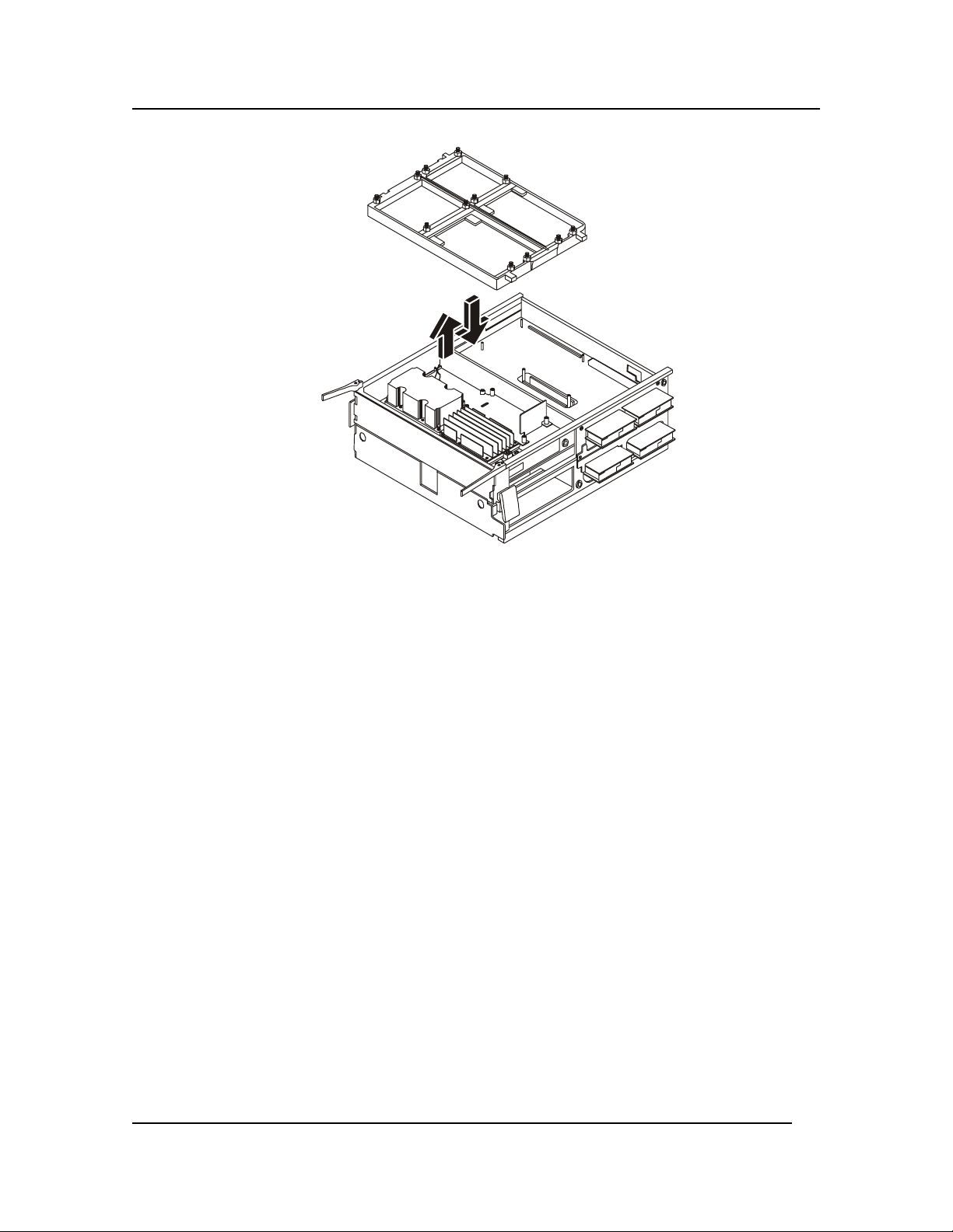
Chapter 6: Installing an Additional Processor
Figure 6-7. The Triple Beam
16. Install the processors and power pods into the bottom half of the Processor/Memory Complex
as described in “Installing an Additional Processor” in Chapter 6.
17. Install the triple beam and the metal baffle.
18. Install the memory board into the bottom half of the Processor/Memory Complex as described
in “Removing and Installing Memory Boards” in Chapter 5.
19. Install the Processor/Memory Complex into the server as described in “Installing the
Processor/Memory Complex” in Chapter 5.
Installing the Board in a System with Two Microprocessors
When installing a board with two microprocessors, complete the following procedure:
1. Place the bottom half of the Processor/Memory Complex on a clean ESD-protected work
surface. The bottom half has wider rails as compared to the top half. Be sure that the rail side
of the complex is in contact with the work surface.
2. Carefully place the Processor Baseboard topside up into position on the bottom half of the
Processor/Memory Complex.
3. Place the top half of the Processor/Memory Complex over the Processor Baseboard. Be sure
that the guide pin relations are correct. The Processor Baseboard should be between the two
Processor/Memory Complex halves.
4. Snap shut the four plastic latches that secure the two halves of the Processor/Memory Complex
together.
5. Tighten the two captive screws that help secure the Processor Baseboard to the
Processor/Memory Complex.
6. Carefully turn the Processor/Memory Complex over so that you can work on the underside.
55
Page 63

Chapter 6: Installing an Additional Processor
7. Install the CPU thermal dummies into the bottom half of the Processor/Memory Complex as
described in “Installing a CPU Thermal Dummy” in Chapter 6.
8. Install the memory board into the bottom half of the Processor/Memory Complex as described
in “Removing and Installing Memory Boards” in Chapter 5.
9. Install the triple beam and metal baffle.
10. Carefully turn the Processor/Memory Complex over so that you can work on the topside.
11. Install the processors and power pods into the top half of the Processor/Memory Complex as
described in “Installing an Additional Processor” in Chapter 6.
12. Install the triple beam and metal baffle.
13. Install the memory board into the top half of the Processor/Memory Complex as described in
“Removing and Installing Memory Boards” in Chapter 5.
14. Install the Processor/Memory Complex into the server as described in “Installing the
Processor/Memory Complex” in Chapter 5.
56
Page 64

Chapter 7: Installing Accessory Boards
7 Installing Accessory Boards
Introduction
The HP Server has ten I/O expansion slots available. PCI slots P1-P2 are 64-bit/33 MHz non-Hot
Plug I/O expansion slots. PCI slots P3-P10 are 64-bit/66 MHz PCI Hot Plug I/O expansion slots . The
PCI expansion slots are contained in four PCI segments:
• F16, 0 provides for PCI slots 1 and 2, video, and the PXB that controls the Super I/O
functions.
• F16, 1 provides for PCI slots 3 through 5 and the dual-channel LVDS controller.
• F16, 2 provides for slots 6 through 8.
• F16, 3 provides for slots 9 and 10.
Tested PCI Boards
For a list of tested PCI boards, check for compatibility in the Hardware Tested Products list for the HP
Server under the Service and Support topic for the specific NOS used in the HP Server at HP’s web
site:
http://www.hp.com/
CAUTION Some accessory board outputs may exceed U.S. National Electrical code (NFPA
70) Class 2 or limited power source limits and must use appropriate
interconnecting cabling in accordance with the National Electrical Code. (All
Hewlett-Packard boards comply with Class 2.)
Also refer to the Readme file and Chapter 10, "Configuring the HP Server," for instructions.
Tools Required
The tools used to remove or add accessory boards in the HP Server include:
• Phillips screwdriver (cross-head with #2 bit)
• Jumper removal tool or needle-nosed pliers
• An anti-static service kit (3M 8501/8502/8503 or equivalent). This kit includes a static-
dissipating work surface, a chassis clip lead, and a wrist strap.
• Equipment log and pencil.
Accessory Board Installation Guidelines
The following sections provide the guidelines necessary to install the PCI accessory boards into the
HP Server.
IRQ Settings
The IRQ settings are automatically assigned and don't require user intervention. The HP Server uses
the Plug-and-Play feature of the PCI boards to correctly assign its resources automatically.
57
Page 65

Chapter 7: Installing Accessory Boards
Boot Priority
The Server’s boot priority (BIOS search order for a boot drive) should be considered when selecting a
PCI slot on the system board. This is especially important if you are installing a board that requires an
early number in the boot order. The board's boot priority is set by its slot location in the boot order.
See Figure 7-3.
The embedded SCSI controller consists of two channels, A and B. Channel A is typically used to
control the internal SCSI drives. Channel B is typically used to control the external SCSI devices or
used with Channel A to create disk duplexing. On each SCSI channel, the HP Server scans for a boot
device starting at device ID 0 and works up from there.
By default the HP Server searches for boot devices in this order:
1. SCSI
2. PM
3. SM
4. PS
5. Other Boot Devices
IDE DVD drive
Flexible disk drive
6. PCI slot 1
7. PCI slot 2
8. PCI slot 3
9. PCI slot 4
10. PCI slot 5
11. PCI slot 6
12. PCI slot 7
13. PCI slot 8
14. PCI slot 9
15. PCI slot 10
Installing Accessory Boards
The HP Server has eight hot swap PCI board slots and two non-hot swap PCI board slots.
Expansion slot covers must be installed on all vacant slots to maintain the electromagnetic
emission characteristics of the server and to ensure proper cooling of the system. The
following procedures detail the steps required to install both types of boards.
Installing a Hot Swap PCI Board
The HP Server has eight hot plug PCI I/O slots in the I/O Baseboard. You can replace a hot plug PCI
I/O board without shutting down the server. However, you must use the operating system or a
resident GUI to shut down or power off the PCI I/O board before you replace it.
The PCI hot-plug (PHP) is a rotating plastic mechanism that actuates a switch located on the PCI hot
plug LED board. Each PCI slot has four indicator LEDs: two on the outside and two on the inside of
58
Page 66

Chapter 7: Installing Accessory Boards
the system. The LEDs operate differently depending upon the operating system installed. Please
refer to your operating system’s manual.
To install a hot swap hot plug PCI I/O board, complete the following steps:
1. If your server is operating, use your operating system or GUI application to make sure the PCI
slot that you are installing the board into is powered down.
WARNING Make sure that the rack is anchored securely, so it will not tip when the server
chassis is extended.
2. Pull the chassis out of the rack as far as it will go.
3. Loosen the two thumbscrews in the back of the chassis that secure the rear part of the top
cover.
4. Lift the rear cover to expose the hot plug PCI slots.
CAUTION Do not touch the components or gold edge connectors on the add-in board as this
may damage the connectors causing erratic performance.
5. Remove the card from its protective wrapper, and place it component-side up on a
nonconductive, antistatic surface.
6. Record in your log the serial number of the board and any jumpers or switch settings according
to the board manufacturer’s instructions. See Appendix B for the equipment log form.
7. Skip to step 8 if you are installing a board in an empty slot. To replace a board or install a
different board in an occupied slot, after the LED shows which slot is powered down, press the
center of the PHP mechanism to disengage it from the LED board.
8. Be sure that the plastic retaining mechanism (I/O Card Guide) that secures the end of the board
nearest the front of the chassis is open so that it will allow a board to be removed/inserted.
Figure 7-1. Open the Plastic Retaining Mechanism Towards the Front of the Server
9. Be sure that the plastic PCI hot plug (PHP) mechanism that secures the end of the board
nearest the rear of the chassis is in the open position. If not, press the center of the PHP until it
clicks open and then rotate the mechanism downward from outside the chassis.
59
Page 67
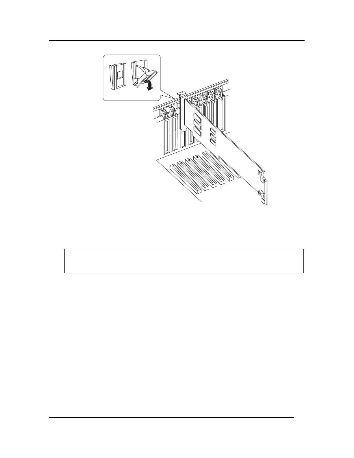
Chapter 7: Installing Accessory Boards
Figure 7-2. Open the PCI PHP Mechanism Securing the Board at the Rear of the Chassis
10. If you are adding a new board, remove the perforated rear panel cover in the slot you’re using
by pushing it out from inside the chassis.
11. Press the PCI board down firmly until it seats in its slot.
CAUTION Some accessory/option board outputs exceed Class 2 or limited power source
limits and must use appropriate interconnecting cabling in accordance with the
national electric code during installation.
12. Close the plastic latching mechanism that secures the end of the board nearest the front of the
chassis.
13. Rotate the PHP mechanism near the rear of the chassis up until it clicks into place. This
position both secures the end of the board and allows it to be activated with the operating
system or GUI application.
14. Close the rear part of the top cover and tighten the two thumbscrews.
15. Connect any required cabling to the add-in board.
16. If your server is operating, use the operating system or GUI application to power up the PCI
I/O slot into which you installed the PCI I/O board.
17. Push the system back into the equipment rack.
Installing a Non-Hot Plug PCI Board
Use this procedure to install a non-hot plug PCI accessory board. Observe the safety guidelines listed
earlier. The server must be shut down before installing a non-hot plug PCI board.
1. If the HP Server is already installed and working, power down the HP Server.
60
Page 68
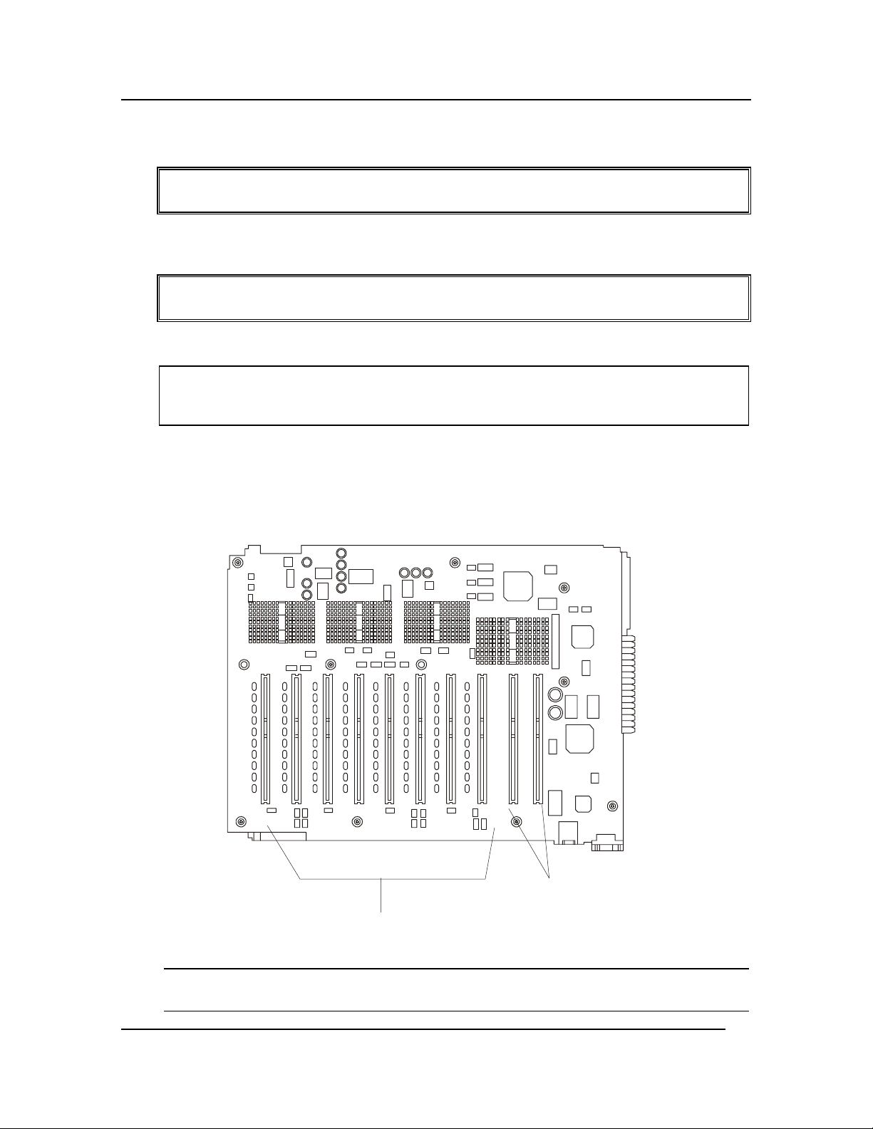
Chapter 7: Installing Accessory Boards
Refer to Chapter 1, "Controls, Ports, and Indicators."
WARNING The power supply will continue to provide standby current to the HP Server until
the power cable is disconnected.
2. Disconnect the power cables and any external cables connected to the HP Server. If necessary,
label each one to expedite re-assembly.
WARNING Make sure that the rack is anchored securely, so it will not tip when the server
chassis is extended.
3. Pull the chassis out of the rack.
CAUTION Wear a wrist-strap and use a static-dissipating work surface connected to the
chassis when handling components. Ensure the metal of the wrist-strap contacts
your skin.
4. Loosen the two thumbscrews in the back of the chassis that secure the rear cover.
Refer to Chapter 2, "Opening and Closing the HP Server."
5. Read the documentation included with the accessory board and follow any special instructions.
6. Identify the accessory slot number to be used. See Figure 7-3.
Non PCI Hot Plug Slots
PCI Hot Plug Slots
Figure 7-3. Accessory Slots
NOTE Refer to the Readme file for the Tested Products List that shows specific slot
recommendations for a particular PCI board type.
61
Page 69
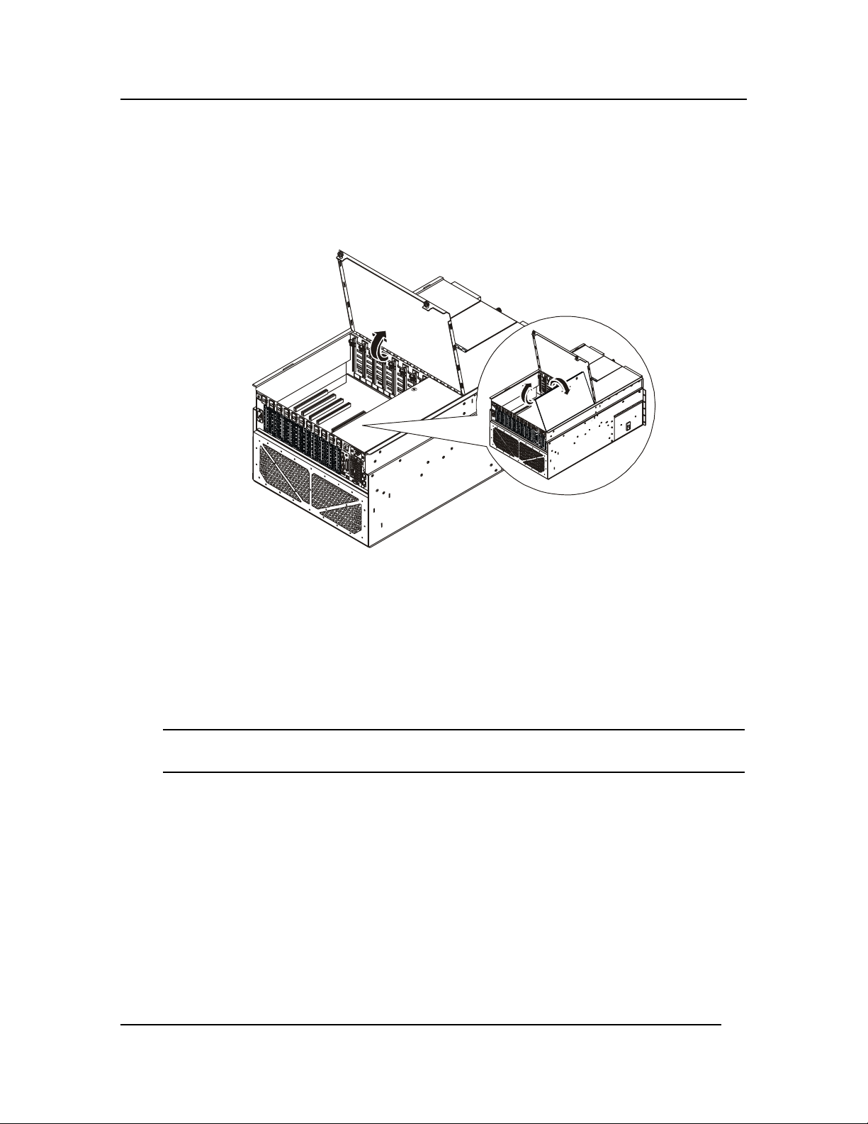
Chapter 7: Installing Accessory Boards
7. Lift the rear cover to expose the non-hot plug PCI adapter board cover.
8. Loosen the screw that secures the non-hot plug PCI adapter board cover.
9. Grasp the cover by its exposed, long side and lift the cover over the non-hot plug boards away
from the chassis. You can completely remove the cover if you want by unseating the slot
hinge. Access is now available to the two non-hot plug PCI slots and the Legacy I/O board.
Figure 7-4. Accessing the Non-Hot Plug Boards
10. Release the plastic retaining mechanism (I/O Card Guide) that secures the end of the board
nearest the front of the chassis so that it will allow a board to be inserted
11. Be sure that the rocker switch that secures the end of the board nearest the rear of the chassis is
in the open position. If not, press the center of the rocker switch until it clicks open and then
rotate the mechanism downward from outside the chassis.
12. If you are adding a new board, remove the perforated rear panel cover in the slot you’re using
by pushing it out from inside the chassis.
NOTE Ensure you save the slot covers for use later to prevent EMI interference. These
slot covers make a better metal-to-metal contact than previous slot cover designs.
13. Being careful not to touch the components or gold edge connectors on the add-in board,
remove it from its protective wrapper and place it component-side up on a nonconductive,
antistatic surface.
14. Record the serial number of the board in your equipment log. See Appendix B for the
equipment log.
15. Press the PCI adapter board down firmly until it seats in its slot.
16. Close the plastic latching mechanism (I/O Card Guide) that secures the end of the board
nearest the front of the chassis.
17. Rotate the rocker switch near the rear of the chassis up until it clicks into place.
18. Install the non-hot plug PCI adapter board cover by aligning the slotted hinge into the chassis
housing, closing the cover, and securing the cover screw.
62
Page 70

Chapter 7: Installing Accessory Boards
19. Attach any cables to the PCI adapter board you just installed.
20. Close the rear part of the top cover and tighten the two thumbscrews.
21. Attach the power cords.
22. Push the system back into place into the equipment rack.
23. Power on any attached peripheral devices.
24. Power on the system.
25. Once the accessory board is installed, you may need to install software drivers. The drivers
for the new board are either part of your existing system software or included on a flexible
diskette provided with the accessory board.
Removing Accessory Boards
The HP Server has eight hot swap PCI board slots and two non-hot swap PCI board slots. You can
remove a hot plug PCI I/O board without shutting down the server, but you must use the operating
system or a resident GUI to shut down or power off the PCI I/O board before removing it. The HP
Server must be shut down before installing a non-hot plug PCI board.
CAUTION Expansion slot covers must be installed on all vacant slots to maintain the
electromagnetic emission characteristics of the server and to ensure proper
cooling of the system.
Removing a Non-Hot Plug PCI Board
To remove a non-hot plug PCI board, complete the following steps:
1. Observe the safety and ESD precautions for handling electronic components.
2. Turn off all peripheral devices connected to the system.
3. Power down the server by pressing and holding the Power button on the Front Control Panel.
You may have to hold the Power button down for several seconds. Remove both AC power
cords. Removing the power cords ensures that the server is not under standby power.
WARNING Make sure that the rack is anchored securely, so it will not tip when the server
chassis is extended.
4. Pull the chassis out of the rack as far as it will go.
5. Loosen the two thumbscrews in the back of the chassis that secure the rear cover.
6. Lift the rear cover to expose the non-hot plug PCI adapter board cover.
7. Loosen the screw that secures the non-hot plug PCI adapter board cover.
8. Grasp the cover by its exposed, long side and lift the cover away from the chassis. You can
completely remove the cover by unseating the slot hinge. Access is now available to the two
non-hot plug PCI slots and the Legacy I/O board.
9. Label and disconnect all peripheral cables attached to the board you are going to remove.
10. Release the plastic retaining mechanism (I/O Card Guide) that secures the end of the board
nearest the front of the chassis.
63
Page 71

Chapter 7: Installing Accessory Boards
11. Press the center of the rocker switch that secures the end of the board nearest the rear of the
chassis. When the mechanism clicks open, rotate it all the way down from the outside of the
chassis.
12. Carefully grasp the adapter board and gently slide it up and out of the system. Be sure not to
allow the board’s components to touch any neighboring boards as you lift the board out of the
system.
13. Place the board component side up on a nonconductive, antistatic surface.
Removing a Hot Plug PCI Board
To remove a hot plug PCI board, complete the following steps:
1. Observe standard safety precautions when working with the server.
2. If your server is operating, use your operating system or GUI application to power down the
PCI slot that contains the board you are going to remove.
WARNING Make sure that the rack is anchored securely, so it will not tip when the server
chassis is extended.
3. Pull the chassis out of the equipment rack as far as it will go.
4. Loosen the two thumbscrews in the back of the chassis that secure the rear cover.
5. Lift the rear cover to expose the hot plug PCI slots.
6. Disconnect any cables attached to the board you are removing.
7. Press the center of the rocker switch that secures the end of the board nearest the rear of the
chassis. When the mechanism clicks open, position it all the way down by rotating it from the
outside of the chassis.
8. Release the plastic retaining mechanism (I/O Card Guide) that secures the end of the board
nearest the front of the chassis.
9. Carefully grasp the adapter board and gently slide it up and out of the system. Make sure that
you do not scrape the board against other components.
10. Store the board in an antistatic protective wrapper.
11. Install an expansion slot over the vacant slot by aligning the cover with the slot from the rear
of the chassis and pressing the cover into the slot.
12. Close the rear part of the chassis top cover and tighten the two thumbscrews.
13. Push the system back into the cabinet rack.
64
Page 72

Chapter 8: Server Management
8 Server Management Boards
Introduction
The server management features are implemented using three microcontrollers: the Baseboard
Management Controller (BMC), the Intelligent Chassis Management Bus Controller (ICMB)
controller on the Legacy I/O board, and the Hot-Swap Controller (HSC) on the Power Distribution
Board (T-Docking). The firmware of the three microcontrollers is field upgradeable using the
Firmware Update utility.
This chapter describes the boards that are utilized by these microcontrollers to provide server
management functions and status:
• I/O Baseboard
• Sideplane Board
• PCI Hot Plug LED Board
• Legacy I/O Board
• Power Distribution Board (T-Docking)
Baseboard Management Controller (BMC)
The Baseboard Management Controller (BMC) is a microcontroller with associated circuitry that
resides on the Legacy I/O board. The primary purpose of the BMC is to autonomously monitor for
system platform management events, and log their occurrence in the non-volatile System Event Log
(SEL). System platform management events include over-temperature and over-voltage conditions as
well as fan failures.
The following is a list of the major functions of the BMC:
• Access to the monitored information so system management software can poll and retrieve the
present status of the platform.
• Functions for the front-side system controls and indicators. These functions include control of
system power, hard-resets, Power LED displays, cooling fault detection, general fault
detection, and power fault LED displays. The BMC provides this control both when the
system is powered down and is functioning on standby power only, and when the system is
powered up.
• Access to the non-volatile Sensor Data Record (SDR) Repository. Sensor Data Records
provide information that the system management software uses to automatically configure
itself for the number and type of Intelligent Platform Management Interface (IPMI) sensors in
the system (e.g. temperature and voltage sensors).
• System Power Control
• Platform Event Paging (PEP) / Platform Event Filtering (PEF)
• Power Distribution Board monitoring
• Temperature and Voltage monitoring
• Fan failure monitoring
65
Page 73

Chapter 8: Server Management
• Processor presence monitoring
• Speaker ‘Beep’ capability on standby and when system is powered up
• Itanium processor SEEPROM interface
• Processor temperature monitoring
• Hot plug PCI slot status monitoring
• Processor bus speed setting
• Chassis fan failure light control
• Chassis power fault light control
• Chassis power light control
• SDR/SEL timestamp clock
• Boardset FRU information interface
• Fault Resilient Booting (FRB)
• System management watchdog timer
• Front panel diagnostic interrupt handling (also called the Init Switch)
• Diagnostics interrupt (Init status monitor)
• Event receiver
• System interface to the IPMB
• Secure mode control, including video blank option monitoring and control and front panel
lock/unlock initiation.
• IPMI Management Controller Initialization Agent
• Magic Packet and Wake on LAN / Power on LAN support
• Emergency Management Port (EMP) interface
Intelligent Chassis Management Bus (ICMB) Controller
The ICMB Controller resides on the Legacy I/O Board. It serves as a bridge between the
internal Intelligent Platform Management Bus (IPMB) and the external Intelligent Chassis
Management Bus (ICMB). The internal IPMB transports server management information
within a system, and the external ICMB transports server management information between
various chassis in a server(s) and peripherals cluster configuration.
Hot Swap Controller (HSC)
The Hot Swap Controller (HSC) resides on the Power Distribution Board (T-Docking). The primary
functions of the HSC are as follows:
• Implements the SAF-TE command set
• Controls the fault lights
66
Page 74

Chapter 8: Server Management
• Provides a path for management information via SCSI
• Retrieves drive fault status, Backplane temperature, and fan failure information via IPMB
• Queries the status of the power distribution board by retrieving information from the BMC via
the IPMB
• Controls drive power-on and power-down, facilitating hot-swapping.
67
Page 75

Chapter 8: Server Management
I/O Baseboard
The I/O Baseboard resides in the upper rear of the chassis and plugs into the Sideplane. After
removing all the PCI I/O boards, you can remove the I/O Baseboard.
Removing the I/O Baseboard
To remove the I/O baseboard, complete the following procedure:
1. Observe all safety and ESD precautions for handling electronic components.
WARNING The power supply will continue to provide standby current to the HP Server until
the power cable is disconnected from the rear panel.
2. Power down the HP Server.
3. Disconnect the power cables.
4. Open the rear cover of the server and remove the non-hot plug PCI adapter board cover by
loosening its screw and unhinging the cover.
5. Remove the top cover as described in “Removing the Top Cover” in Chapter 2.
6. Remove the Legacy I/O board as described in “Removing the Legacy I/O Board” in Chapter 8.
7. Disconnect the cable to the external SCSI port from the I/O Baseboard.
Disconnect the external SCSI cable from I/O Baseboard
Remove protective
Sideplane cover
Figure 8-1. Removing the SCSI Cable from the I/O Baseboard
8. Loosen the captive screw to disconnect and remove the external SCSI port from the chassis I/O
connector at the rear of chassis.
9. Remove all non-hot plug PCI and hot plug PCI I/O adapter boards as described in “Removing
Accessory Boards” in Chapter 7.
10. Remove all PCI slot plastic dividers.
11. Loosen the thumbscrew at the back of the chassis holding the protective cover over the DC-DC
converters on the Sideplane, and remove the cover.
68
Page 76

Chapter 8: Server Management
12. Remove all DC-DC converters from the Sideplane.
Figure 8-2. Removing the Sideplane DC-DC Converters
13. Loosen the two captive screws that hold the plastic shield over the I/O Baseboard. These
screws also secure the baseboard tray to the server chassis.
14. Remove the PCI LED cable.
15. Remove the plastic shield.
16. Remove the Internal SCSI cable for the hard drives from the board.
17. Use the two extraction/installation levers on the sides of the I/O Baseboard to pull it clear of
the connector on the Sideplane.
18. Once loose, slide the I/O Baseboard in the direction of the levers against the chassis frame.
Figure 8-3. I/O Baseboard Removal
19. Lift the connector end out of the chassis first followed by the rest of the I/O Baseboard.
20. Place on a clean ESD-protected work surface.
69
Page 77

Chapter 8: Server Management
21. Remove the nine screws and the two hex jackscrews that secure the video connector to the I/O
Baseboard in order to separate it from the I/O Baseboard tray.
Installing the I/O Baseboard
To install the I/O Baseboard, complete the following procedure:
1. Observe all safety and ESD precautions for handling electronic components.
2. Install the I/O Baseboard into the I/O Baseboard tray.
3. Orient the I/O Baseboard and tray assembly such that the connector end faces the Sideplane.
4. Angle the I/O Baseboard such that the side with the two extraction/installation levers lowers
into the chassis first.
5. Slide the lever end of the I/O Baseboard against chassis frame then lower the connector end
into the chassis.
6. Slide the I/O Baseboard towards the Sideplane until lever aligns with the locking slots.
7. Rotate the levers downward to press the I/O Baseboard securely into the Sideplane.
8. Connect the Internal SCSI cable to the front of the I/O Baseboard.
9 Install the plastic shield over the I/O Baseboard and tighten the two thumbscrews that secure
the shield and the I/O Baseboard in the chassis.
10. Connect the PCI LED cable.
11. Install the DC-DC converters on the Sideplane. The voltages are marked on the power supplies
and near the sockets on the baseboard.
12. Install the protective cover over the DC-to-DC converters on the Sideplane, and secure the
cover with the thumbscrew.
13. Connect the cable to the external SCSI port at both ends: one to the I/O Baseboard and the
other secured to the rear of the chassis with the captive thumbscrew.
14. Install the Legacy I/O board and cables as described in “Installing the Legacy I/O Board”.
15. Install the non-hot plug PCI and hot plug PCI adapter boards as described in “Installing
Accessory Boards” in Chapter 7.
16. Install all PCI slot plastic dividers (I/O Card Dividers) as required.
17. Install the top cover as described in “Replacing the Top Cover” in
Chapter 2.
18. Attach the non-hot plug PCI adapter board cover and secure it with its screw.
19. Close the PCI I/O access door, and secure it with the two captive thumbscrews.
20. Reconnect the power cables.
70
Page 78

Chapter 8: Server Management
Sideplane Board
The Sideplane is attached inside the left wall at the rear of the chassis. It receives the I/O Baseboard
as well as the Power Distribution Board (T-Docking). To remove the Sideplane you must remove the
Power Distribution Board (T-Docking), the I/O Baseboard, and the Processor/Memory Complex.
Removing the Sideplane Board
To remove the Sideplane board, complete the following procedure:
1. Observe all safety and ESD precautions for handling electronic components.
2. Remove the I/O Baseboard as described in “Removing the I/O Baseboard” in this chapter.
3. Remove the Power Distribution Board (T-Docking) as described in “Removing the Power
Distribution Board (T-Docking)” in this chapter.
4. Remove the Processor/Memory Complex as described in “Removing the Processor/Memory
Complex” in Chapter 5.
a) Remove the sheet-metal cover protecting the D2D converts on the sideplane board.
b) Remove the D2D converters from the sideplane board.
NOTE Do not remove the screws that hold the Sideplane to the mounting plate.
5. Loosen the captive thumbscrews on the Sideplane that secure it and its mounting plate to the
chassis.
Loosen the three captive thumb screws.
Figure 8-4. Removing the Screws from the Sideplane
6. Slide the Sideplane towards the front of the chassis. As you slide the board, keep the front
bottom edge of the board in contact with the carrier tray as the board is rotated up and out of
the chassis.
71
Page 79

Chapter 8: Server Management
7. Tilt the Sideplane up and out of the chassis.
8. Remove the two retaining screws from the Sideplane to remove the mounting plate.
Figure 8-5. Remove the Sideplane
Installing the Sideplane Board
To install the Sideplane board, complete the following steps:
1. Observe all safety and ESD precautions for handling electronic components.
2. Install the Sideplane on to the mounting plate by tightening the two mounting plate screws.
3. Lower the board into the side of the chassis, and slide it toward the rear of the chassis back into
position. The front lower corner of the board is the rotation point you should use when
positioning the board into place.
4. Tighten the captive thumbscrews on Sideplane to secure it to the chassis.
5. Reinstall the Power Distribution Board (T-Docking) as described in “Installing the Power
Distribution Board (T-Docking)”.
6. Reinstall the I/O Baseboard as described in “Installing the I/O Baseboard”.
7. Reinstall the Processor/Memory Complex as described in “Installing the Processor/Memory
Complex” in Chapter 5.
PCI Hot Plug LED Board
The PCI Hot Plug LED Board resides just on the inside of the top rear of the chassis. This board
enables PCI hot plug boards to be plugged into and out of the system without it being shut down.
Removing the PCI Hot Plug LED Board
To remove the PCI Hot Plug LED Board, complete the following procedure:
1. Observe all safety and ESD precautions for handling electronic components.
2. Turn off all peripheral devices connected to the system.
3. Power down the server by pressing and holding the Power button on the Front Control Panel.
You may have to hold the Power button down for several seconds. Removing the power cords
ensures that the server is not under standby power.
72
Page 80

Chapter 8: Server Management
WARNING Make sure that the rack is anchored securely, so it will not tip when the server
chassis is extended.
4. Pull the chassis out of the rack as far as it will go.
5. Loosen the two thumbscrews in the back of the chassis that secure the rear cover.
6. Lift the rear cover to expose the non-hot plug PCI adapter board cover.
7. Loosen the screw that secures the non-hot plug PCI adapter board cover.
8. Grasp the cover by its exposed, long side and lift the cover away from the chassis. You can
completely remove the cover if you want by unseating the slot hinge. Access is now available
to the PCI Hot Plug LED Board.
9. Disconnect the cable attached to the PCI Hot Plug LED Board.
10. Locate and remove the four small, black plastic retaining pins on the board. The pins are
evenly spaced across the length of the board. To unlock the pin, grasp the head of the pin from
the inside and pull it until it clicks.
11. Carefully pull the PCI Hot Plug LED Board away from the inside of the chassis and place it on
an antistatic surface.
Installing the PCI Hot Plug LED Board
To install the PCI Hot Plug LED Board, complete the following steps:
1. Observe all safety and ESD precautions for handling electronic components.
2. Carefully place the PCI Hot Plug LED Board on the inside back of the server chassis in such a
way as to line up the four, black pin receptacles with their respective holes.
NOTE It is suggested that you place a piece of paper on the inside of the chassis just
below the board as you insert the black retaining pins as a safeguard should they
slip from your fingers.
3. Press the pins through the holes in the board and through their receptacles in the chassis.
4. Connect the cable to the PCI Hot-Plug LED Board.
5. Attach the non-hot plug PCI adapter board cover to the chassis and secure it with the screw.
6. Close the rear part of the top cover and secure it by tightening the two thumbscrews in the
back.
7. Install the power cords.
8. Push the server back into the equipment rack.
9. Power-on the system.
10. Turn on all peripheral devices connected to the system that you shut down during this
procedure.
73
Page 81

Chapter 8: Server Management
Legacy I/O Board
The Legacy I/O Board is plugged into the I/O Baseboard in the rear of the chassis. It is accessible
only when you remove or lift the non-hot plug PCI adapter board cover.
Removing the Legacy I/O Board
To remove the Legacy I/O Board, complete the following procedure:
1. Observe all safety and ESD precautions for handling electronic components.
2. Turn off all peripheral devices connected to the system.
3. Power down the server by pressing and holding the Power button on the Front Control Panel.
You may have to hold the Power button down for several seconds. Removing the power cords
ensures that the server is not under standby power.
WARNING Make sure that the rack is anchored securely, so it will not tip when the server
chassis is extended.
4. Pull the chassis out of the rack as far as it will go.
5. Label and disconnect all peripheral cables attached to the Legacy I/O board’s back panel on
the back of the system.
6. Loosen the two thumbscrews in the back of the chassis that secure the rear cover.
7. Lift the rear cover to expose the non-hot plug PCI adapter board cover.
8. Loosen the screw that secures the non-hot plug PCI adapter board cover.
9. Grasp the cover by its exposed, long side and lift the cover away from the chassis. You can
completely remove the cover if you want by unseating the slotted hinge. Access is now
available to the Legacy I/O board.
10. Release the plastic retaining mechanism (I/O Card Guide) that secures the end of the board
nearest the front of the chassis.
11. Loosen and remove the screw that secures the end of the board at the rear of the chassis.
12. Carefully grasp the board and gently slide it up so that you can access the cables described in
the next two steps.
13. Remove the server management cable from the Legacy I/O board.
74
Page 82
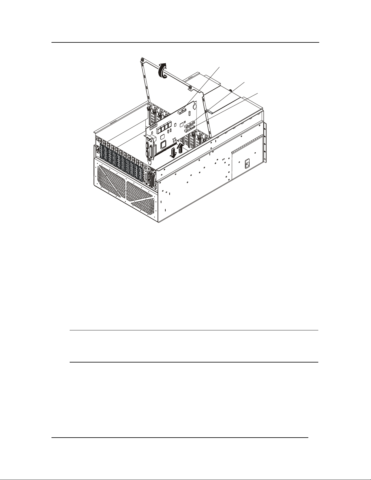
Chapter 8: Server Management
Server Management
Cable
DVD Cable
Floppy Disk
Drive Cable
Figure 8-6. Removing Legacy I/O Board
14. Remove both IDE cables (DVD and Floppy Disk Drive) from the Legacy I/O board by
grasping the ends of the cable connectors and rocking them out of their respective connectors.
15. Carefully lay the board component side up on an antistatic work surface or inside proper
packaging.
Installing the Legacy I/O Board
To install the Legacy I/O Board, complete the following procedure:
1. Observe the safety and ESD precautions at the beginning of this chapter.
2. Be sure that the plastic retaining mechanism (I/O Card Guide) that secures the end of the board
nearest the front of the chassis is open so that it will allow a board to be inserted.
NOTE Being careful not to touch the components or gold edge connectors on the I/O
Legacy board, remove it from its protective wrapper, and place it component-side
up on a nonconductive, antistatic surface within reach of the primary and
secondary IDE cables in the server.
3. Record the serial number of the board in your equipment log.
4. Connect the primary and secondary IDE cables to their respective connectors on the I/O
Legacy board.
5. Connect the server management cable to the Legacy I/O board.
6. Press the board down firmly until it seats in its slot.
7. Attach the rear screw that secures the board to the chassis.
75
Page 83

Chapter 8: Server Management
8. Close the plastic latching mechanism that secures the end of the board nearest the front of the
chassis.
9. Install the non-hot plug PCI adapter board cover by aligning the slotted hinge into the chassis
housing, closing the cover, and securing the cover screw.
10. Close the rear part of the top cover and secure it by tightening the two thumbscrews in the
back.
11. Attach any peripherals to the rear panel of the Legacy I/O board.
12. Install the power cords to the system.
13. Push the system into the equipment rack.
14. Power-on the system.
15. Turn on all peripheral devices connected to the system that you shut down during this
procedure.
76
Page 84

Chapter 8: Server Management
Changing the Legacy I/O Board Battery
The lithium battery on the Legacy I/O board powers the real-time clock (RTC) for three to four years
in the absence of power. When the battery weakens, it loses voltage and the system settings stored in
CMOS RAM in the Real Time Clock (such as the date and time) can be wrong. Contact your
customer service representative or dealer for a list of approved devices.
WARNING There is a danger of explosion if the battery is incorrectly replaced. Replace the
battery only with the same or an equivalent type recommended by the equipment
manufacturer.
Removing the Battery
To remove the battery, complete the following steps:
1. Observe the safety and ESD precautions at the beginning of this chapter.
2. Remove the Legacy I/O board as described in “Removing and Installing the Legacy I/O
Board” on page 126.
3. Insert the tip of a small flat-bladed screwdriver or equivalent under the plastic tab on the snapon plastic retainer holding the battery on the Legacy I/O board.
4. Gently push down on the screwdriver to lift the battery.
5. Remove the battery from its socket.
6. Dispose of the battery according to local ordinance.
Installing the Battery
To install a new battery, complete the following steps:
1. Remove the new lithium battery from its package and, being careful to observe the correct
polarity, insert it in the battery socket.
2. Close the plastic tab over the battery.
3. Install the Legacy I/O board as described in “Removing and Installing the Legacy I/O Board”
in this chapter.
4. Close the rear portion of the top chassis cover.
77
Page 85

Chapter 8: Server Management
Power Distribution Board (T-Docking)
The Power Distribution Board (T-Docking) resides in the upper front half of the chassis above the 172
mm fans. You can access it by removing the top cover of the chassis and removing the Hard Drive
Bay.
Removing the Power Distribution Board (T-Docking)
1. Observe all safety and ESD precautions for handling electronic components.
2. Turn off all peripheral devices connected to the system.
3. Power down the server by pressing and holding the Power button on the Front Control Panel.
You may have to hold the Power button down for several seconds. Removing the power cords
ensures that the server is not under standby power.
WARNING Make sure that the rack is anchored securely, so it will not tip when the server
chassis is extended.
4. Remove the top cover as described in “Removing the Top Cover” in Chapter 2.
5. Remove all power supplies as described in “Hot Swapping Power Supplies” in Chapter 3.
6. Disconnect the data and power cables from the DVD and the LS120 drive. Place the cables in
the I/O bay area.
7. Disconnect the Server Management cable from the Power Distribution Board (T-Docking).
8. Disconnect the Internal SCSI cable from the I/O Baseboard.
9. Loosen the captive screw on top of the Power Distribution Board (T-Docking) bracket and
remove the bracket.
78
Page 86
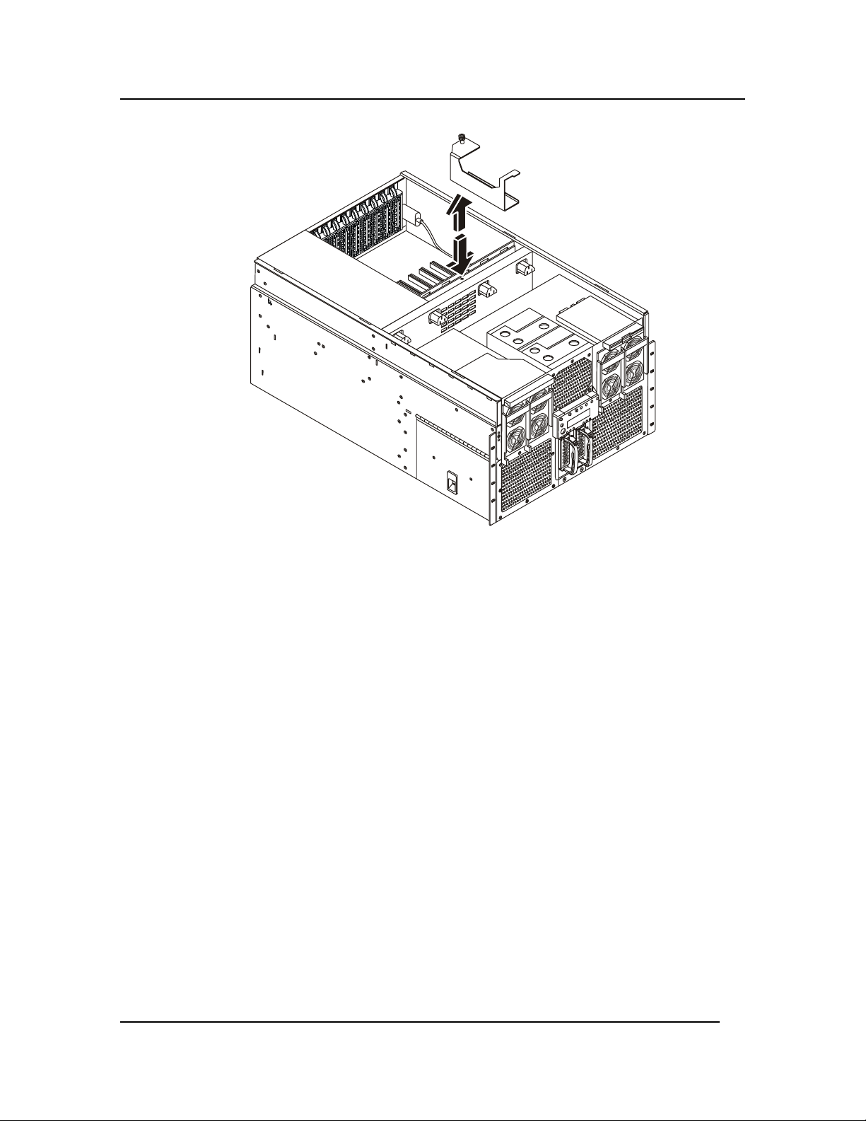
Chapter 8: Server Management
Figure 8-7. Removing the Power Distribution Board (T-Docking)’s Top Bracket
10. Remove the 12 V DC-DC converter from the top of the Power Distribution Board (TDocking).
11. Remove the fan, DVD, and floppy drive cable power connector from the Power Distribution
Board by squeezing the lock tab and carefully pulling the connector upwards.
12. Loosen the two top captive screws from the AC Power Distribution Bracket. Lift the AC
distribution bracket out of the way and disconnect the AC input cables from both connectors.
79
Page 87
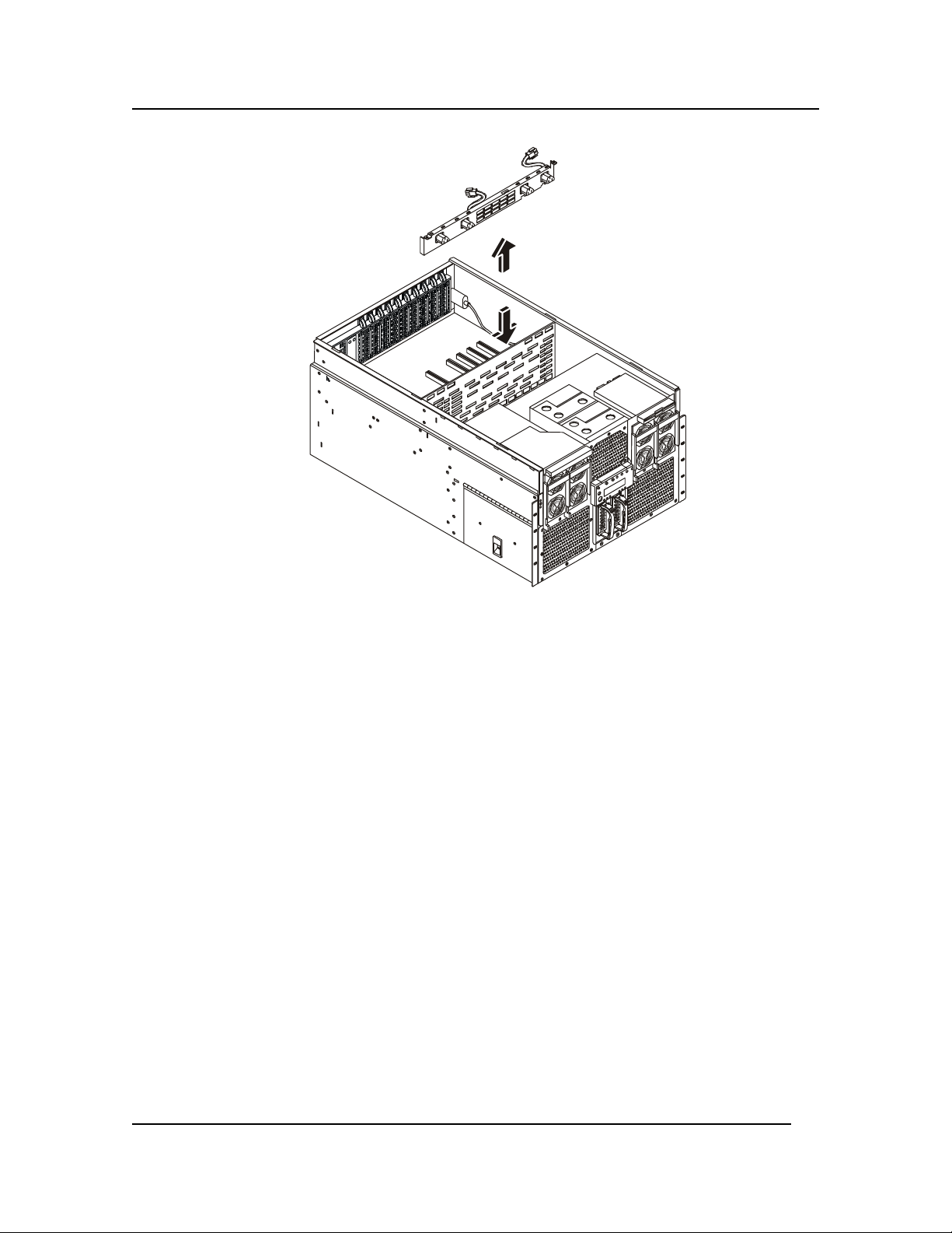
Chapter 8: Server Management
Figure 8-8. Removing the AC Distribution Bracket
13. Loosen the six captive thumbscrews securing the Power Distribution Board plastic overlay.
Remove the overlay.
14. Remove the two hot swap drives from the Hard Drive Bay.
15. Remove the four screws securing the Hard Drive Bay and pull the bay completely out of the
chassis.
80
Page 88
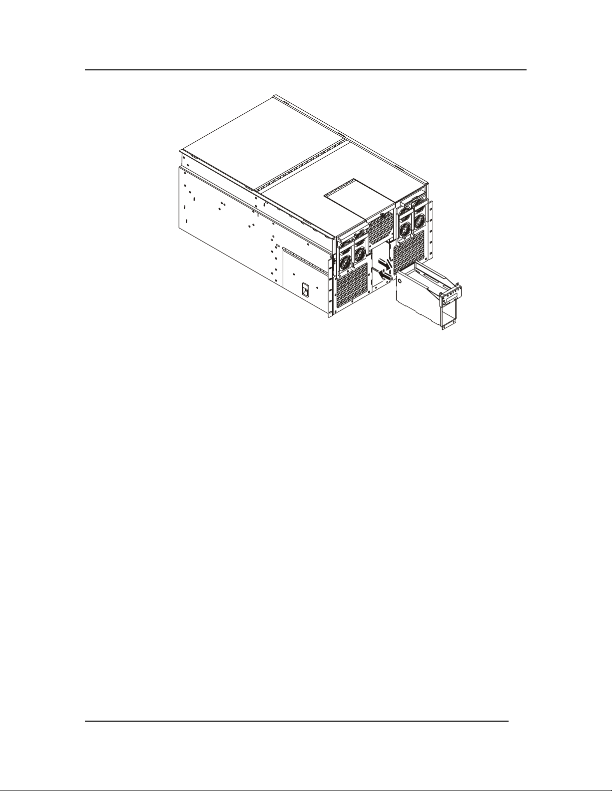
Chapter 8: Server Management
Figure 8-9. Removing the Hard Drive Bay from the Chassis
16. Disconnect the two 172 mm fan cables from the bottom side of the Power Distribution Board
(T-Docking). You can access these cables from the emptied Hard Drive Bay.
17. Lift the small handle mounted to the top of the Power Distribution Board (T-Docking) near the
Sideplane to disengage the Power Distribution Board (T-Docking) from the Sideplane.
18. Grasp the Power Distribution Board (T-Docking) by the right-rear edge and lift up to remove it
from the chassis.
81
Page 89
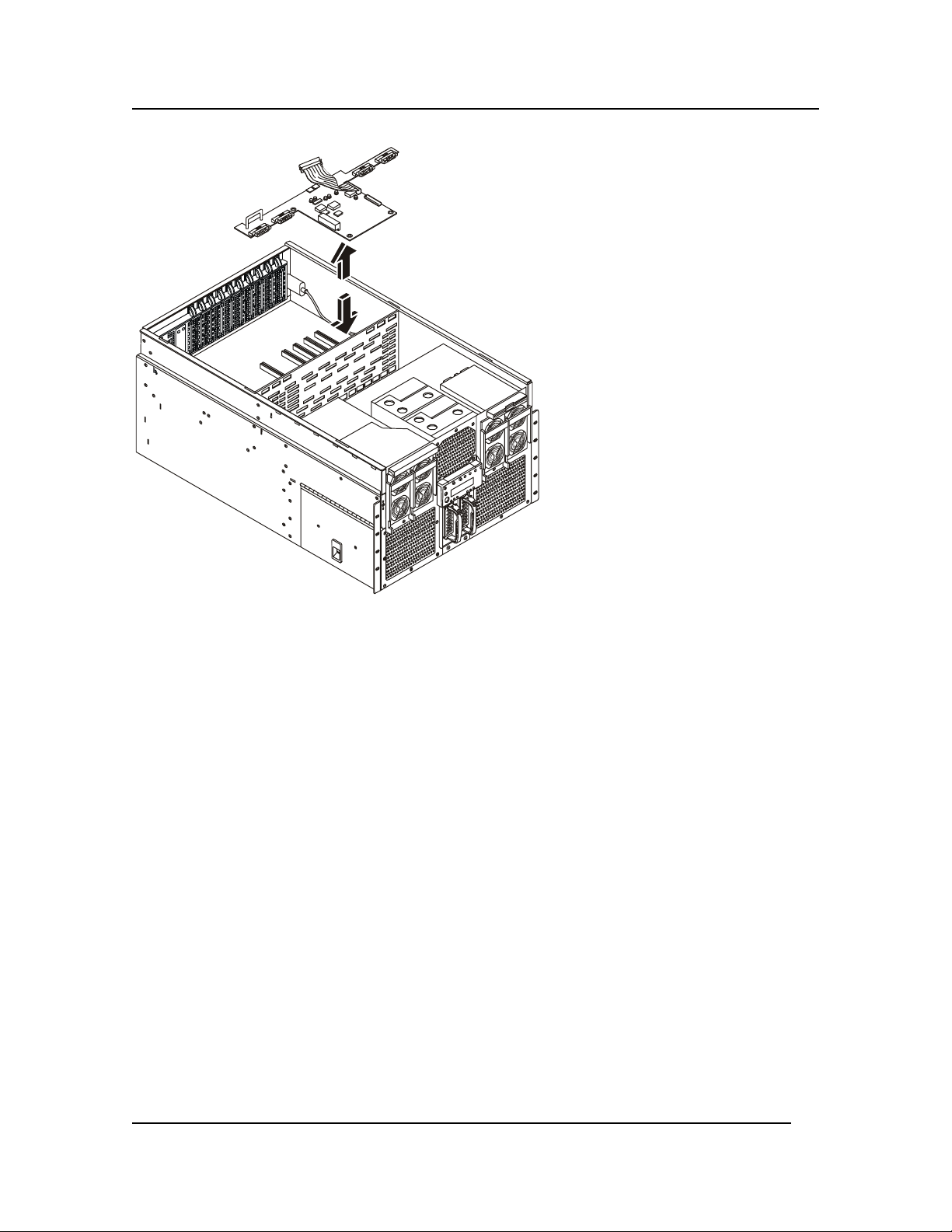
Chapter 8: Server Management
Figure 8-10. Removing the Power Distribution Board (T-Docking)
Installing the Power Distribution Board (T-Docking)
To install the Power Distribution Board (T-Docking), complete the following procedure:
1. Remove the U-shaped handle on the original Power Distribution Board (T-Docking) and attach
it to the replacement board.
2. Place the Power Distribution Board (T-Docking) into position, taking care to locate the board
over the indexing stake in the middle and not over the SCSI cable.
3. Engage the connector on the side of the Power Distribution Board (T-Docking) to the
Sideplane. Be sure that the connector on the Power Distribution Board (T-Docking) is aligned
correctly with the Sideplane before pressing the board down.
4. Connect the 172 mm fan cables to the underside of the Power Distribution Board (T-Docking).
You can make the connection through the emptied Hard Drive Bay.
5. Reinsert the Hard Drive Bay and secure the four front screws.
6. Reinsert the two hot swap drives into the Hard Drive Bay.
7. Connect the Internal SCSI cable to the I/O Baseboard.
8. Install the 120 mm fan cable into the top of the Power Distribution Board (T-Docking).
9. Connect the DC-DC converter to the top of the Power Distribution Board (T-Docking).
10. Connect AC input cables to both connectors on the AC Power Distribution bracket.
11. Align the AC input bracket and install the two screws to secure it.
82
Page 90

Chapter 8: Server Management
12. Install the bracket between the 120 mm fan housing and the AC input bracket. Make sure that
the fan cable can reach the connector on the Power Distribution Board (T-Docking).
13. Install the Server Management cable.
14. Connect the power and data cables to the DVD and LS120 drives.
15. Install the power supplies.
16. Install the top cover as described in “Replacing the Top Cover” in
Chapter 2.
83
Page 91

9 Connecting the Monitor, Keyboard, and Mouse
Introduction
The PS/2 compatible keyboard and mouse connectors as well as the connection for the monitor are
mounted on the rear panel of the server. The keyboard, mouse, and monitor should be plugged in
before powering up the HP Server rx4610. The BIOS detects these peripherals and configures them
accordingly.
Figure 9-1. Rear Panel Ports
Use this procedure to connect the peripheral control devices and monitor to the
HP Server:
CAUTION The Keyboard and Mouse ports are both PS/2 ports, but are not interchangeable.
If you plug the keyboard into the Mouse port, or the mouse into the Keyboard
port, you will get an error message and the system will not finish the boot process.
1. Connect the monitor, keyboard, and mouse to the HP Server using the connections provided on
the rear of the chassis. See Figure 9-1.
84
Page 92

Chapter 9 Connecting the Monitor, Keyboard, and Mouse
NOTE The two USB connectors are reserved for printers, scanners, and external modems,
but not the keyboard or mouse.
If you have a console switch box, refer to the switch box's user guide for
instructions on connecting the keyboard, mouse, and monitor.
2. If a LAN connector is provided, you may connect it now, or wait until you have verified the
HP Server's operation.
85
Page 93

Chapter 10: Configuring the HP Server
10 Configuring the HP Server
Introduction
This chapter provides instructions for the utilities provided with your
HP Server. It supplements the basic installation steps provided in the “HP Server rx4610 Installation
Guide”. The CD-ROM shipped with your server contains the latest information regarding the various
software and firmware utilities.
Configuring the HP Server
These utilities are used for powering on the system, modifying the standard configuration, initial
server set up, testing functionality, and upgrading your server. The following procedures are
described below:
• Power-on Sequence and Power-on Self Test
• EFI Boot Manager
• Server Management Configuration Utility
• BIOS Setup Utility
• QLogic SCSI Utility
• SELViewer Utility
• SDR Viewer Utility
• IFlash64
• FWUpdate
• FDUSDR
Power-on Sequence and Power-on Self Test (POST)
Turning on the system causes POST to run and control to pass to the Boot Manager. From the Boot
Manager, you can choose to invoke the EFI Shell or you can choose to go to the Boot Maintenance
Menu. For information on the Boot Manager, refer to “The Extensible Firmware Interface (EFI) Boot
Manager”. For information on the EFI Shell, refer to “The Extensible Firmware Interface (EFI)
Shell”.
Follow these steps to power up the HP Server:
1. Press the Power on/off button on the Front Control Panel. Pressing this button causes the
server fans to start up and POST begins to run. You can monitor boot progress in two different
places: the video display and the LCD display on the Front Panel. Information appears in the
LCD display first.
NOTE To enter the BIOS Setup Utility you must immediately start pressing <F2>
repeatedly after you first power on the server. Doing so interrupts the boot process
86
Page 94

Chapter 10: Configuring the HP Server
and allows you to use the utility. For more information on entering and using the
utility, refer to “Using BIOS Setup” in this chapter.
2. POST begins running. POST checks the drive carriers, processors, memory, keyboard, and
most installed peripheral devices. During the memory test, POST displays the amount of
memory it is able to access and test. The length of time needed to test memory depends on the
amount of memory installed. POST is stored in flash memory.
3. The LCD displays boot progress as follows:
Boot,First Row Test (should always be 64MB)
Base Memory Test (2GB max)
Ext Memory Test (will report out if enough memory is available)
CMOS Test
Keybrd Bat Test
Initialize Timer
PCI Bus Scan
Initialize Video
Keyboard Test
Initialize IDE
Serial Test
Prepare to Boot
Processor Speed
4. Video appears on the monitor attached to the system and begins to display boot progress.
◊◊◊◊ AMI BIOS banner: displays the loaded versions of the BIOS, PAL, SAL, and EFI.
◊◊◊◊ QLogic banner: allows you the opportunity to enter the QLogic SCSI utility by entering
the key combination <Alt-Q>. The QLogic SCSI utility allows you to manage and
configure the server’s SCSI devices. For information on the screens available in this
utility, refer to “QLogic SCSI Utility”.
5. POST concludes and passes control to the Boot Manager.
6. From the Boot Manager, you can use arrow keys to highlight the option that invokes the EFI
Shell, or you can highlight and select the Boot Maintenance Menu. Booting to the EFI Shell
causes the following prompt to appear:
Shell>
7. When you see the Shell> prompt, load and start the operating system.
The Extensible Firmware Interface (EFI) Boot Manager
The EFI Boot Manager allows you to control the server’s booting environment. Depending on how
you have configured the boot options, after the server is powered up the Boot Manager presents you
with different ways to bring up the system. For example, you can boot to the EFI Shell, to an
operating system located on the network or residing on media in the server, or the Boot Maintenance
Menu.
87
Page 95

Chapter 10: Configuring the HP Server
EFI Shell A simple, interactive environment that allows EFI
device drivers to be loaded, EFI applications to be
launched, and operating systems to be booted. In
addition, the shell also provides a set of basic
commands used to manage files and the system
environment variables. For more information on the
EFI Shell, refer to “The Extensible Firmware
Interface (EFI) Shell”.
Boot Options Files that you include as boot options. You add and
delete boot options by using the Boot Maintenance
Menu. Each boot option specifies an EFI executable
with possible options. For information on the Boot
Maintenance Menu options, refer to Table 10-1.
Boot Maintenance
Menu
A menu of items that let you configure boot options and
configure other boot environment variables.
88
Page 96

Chapter 10: Configuring the HP Server
Table 10-1 describes each menu item in the Boot Maintenance Menu.
Table 10-1. Boot Maintenance Menu Options
Option Description
Boot from a File Automatically adds EFI applications as boot options or
allows you to boot from a specific file.
When you choose this option, the system searches all the
EFI System Partitions in the system. For each partition
it looks for an EFI directory. If the EFI directory is
found, then it looks in each of the subdirectories below
EFI. In each of those subdirectories, it looks for the first
file that is an executable EFI Application. Each of the
EFI Applications that meet this criterion can be
automatically added as a boot option. In addition,
legacy boot options for A: and C: are also added if those
devices are present.
You can also launch a specific application without
adding it as a boot option. In this case the EFI Boot
Manager searches the root directories and the
\EFI\TOOLS directories of all of the EFI System
Partitions present in the system for the specified EFI
Application.
Add a Boot Option Adds a boot option to the EFI Boot Manager. You
specify the option by providing the name of the EFI
application. Along with the name you can also provide
either ASCII or UNICODE arguments the file might use.
Given the EFI application name and any options, the EFI
Boot Manager searches for the executable file in the
same partitions and directories as described in “Boot
from a File” option. When the file is found, it is
executed.
Delete Boot
Options
Allows the user to delete a specific boot option or all
boot options.
Change Boot Order Allows the user to control the relative order in which the
EFI Boot Manager attempts boot options. For help on
the control key sequences you need for this option, refer
to the help menu.
Manage BootNext
Setting
Set Automatic
Boot Timeout
Allows the user to select a boot option to use one time
(the next boot operation).
Allows you to define the value in seconds that pass
before the system automatically boots without user
intervention. Setting this value to zero disables the
timeout feature.
Close Redir &
Return EMP Mode
to Active
Allows you to switch the COM2 from the system port
(used for redirection) and gives control of the COM2
port to EMP (Emergency Management Port).
Cold Reset Performs a platform-specific cold reset of the system. A
cold reset traditionally means a full platform reset.
89
Page 97

Chapter 10: Configuring the HP Server
Option
Description
Exit Returns control to the EFI Boot Manager main menu.
This will display the active boot devices, including a
possible integrated shell (if the implementation is so
constructed).
The Extensible Firmware Interface (EFI) Shell
The EFI Shell is an EFI application that allows other EFI Applications to be launched. The
combination of the EFI firmware and the EFI Shell provide an environment that can be modified to
easily adapt to many different hardware configurations. The EFI shell is a simple, interactive
environment that allows EFI device drivers to be loaded, EFI applications to be launched, and
operating systems to be booted. In addition, the shell also provides a set of basic commands used to
manage files and the system environment variables.
After booting the server to the EFI Shell, you have all its commands available to you. Table 10-2
provides a brief description of the commands.
In addition to shell commands made available to you, the EFI environment allows you to create your
own shell commands and EFI applications. For detailed information about the EFI Shell, its
commands, and the ability to develop within the environment, refer to the EFI Developer’s Guide. To
find this guide, you must download the “EFI sample implementation source code” from the sample
implementation download area of the Extensible Firmware Interface Web Site. Go to the following
URL and click on the “EFI sample implementation source code”. Once you download the sample,
locate the Microsoft Word file named “Efi_dg.doc” in the “Notes” folder.
http://developer.intel.com/technology/efi/downsource.htm.
Table 10-2. EFI Shell Commands
Command Description
<drive_name>: Changes drives. For example, entering a:
and pressing the <ENTER> key changes
the drive to the LS120 drive.
alias [-bdv] [sname] [value] Sets or gets alias settings
attrib [-b] [+/- rhs] [file] Views or sets file attributes
bcfg -? Configures boot driver & load options
cd [path] Updates the current directory
cls [background color] Clear screen
comp file1 file2 Compare two files
cp file [file] ... [dest] Copy files and directories
date [mm/dd/yyyy] Gets or sets the date
dblk device [Lba] [Blocks] Hex dump of BlkIo Devices
dh [-b] [-p prot_id] | [handle] Dumps handle info
dmpstore Dumps variable store
echo [[-on | -off] | [text] Echos text to stdout or toggle script echo
Edd30 [On | Off] Enables or Disables EDD 3.0 Device Paths
edit [filename] Edits a file
90
Page 98

Chapter 10: Configuring the HP Server
Command
Description
endfor Delimiter for loop constructs (scripts only)
endif Delimiter for IF THEN constructs (scripts
only)
err [level] Sets or displays error level
for var in <set> Loop constructs (scripts only)
goto label Jumps to label locations (scripts only)
guid [-b] [sname] Dumps known guid ids
help [-b] [internal_command] Displays help information.
if [not] condition then Conditional construct (scripts only)
load driver_name Loads a driver
ls [-b] [dir] [dir] ... Obtains directory listing
map [-bdvr] [sname[:]] [handle] Maps sname to device path
mem [address] [size] [;MMIO] Dumps Memory or Memory Mapped IO
memmap [-b] Dumps memory map
mkdir dir [dir] Makes a directory
mm address [Width] [;Type] Memory Modify: Mem, MMIO, IO, PCI
mode [col row] Sets or gets the current text mode
mount BlkDevice [sname[:]] Mounts a file system on a block device
PalProc arg1 [arg2] [arg3] [arg4] Makes a PAL call
pause Prompt to quit or continue (scripts only)
pci [bus_dev] [func] Displays PCI device information
reset [/warm] [reset_string] Performs a cold or warm reset
rm file/dir [file/dir] Removes files or directories
set [-bdv] [sname] [value] Sets or gets environment variables
stall microseconds Delays for the specified number of
microseconds
time [hh:mm:ss] Gets or sets the time
type [-a] [-u] [-b] file Displays the contents of a file
ver Displays version information
vol fs [volume_label] Sets or displays a volume label
91
Page 99

Chapter 10: Configuring the HP Server
Server Management Configuration Utility
The Server Management Configuration Utility (SM Config) is an EFI-based program used to view or
modify the Server Management firmware configuration data. The firmware configuration is
maintained by the BMC. The executable program for the utility is named SMconfig.efi. SM Config
provides the following functions:
• Configure the Emergency Management Port (EMP) for remote server management over a
modem or direct serial connection.
• Configure the Direct Platform Control over LAN feature (DPC\LAN) for remote server
management over the network.
• Configure power restoration policies when the system loses AC power.
• Set the accelerated cool-down timeout.
• Set the Fault Resilient Boot (FRB) timeout.
• Configure the Advanced Configuration and Power Interface (ACPI) features.
• Enable or disable Platform Event Filtering (PEF) and Platform Event Paging (PEP).
Running the Server Management Configuration Utility
Follow these steps to run the SM Config Utility:
1. Boot to the EFI Shell.
2. Change to the SMCONFIG directory located on the EFI Based Offline Utilities disk.
3. Load the IPMI driver by typing the following command:
load ipmi.efi
4. Run the utility by typing the following command:
smconfig
The utility automatically loads configuration data from the smconfig.ini file. This data is used to
build the contents of the Config Data pull-down menu in the utility
Main Window
The SM Config pull-down menu lets your select the main features of the utility. To access menu
items, use the arrow keys. Press the <Enter> key to select a menu item. A brief description of each
menu item is displayed in the tip-view window at the bottom of the screen.
File Open
When an ini file is opened, SM Config validates the contents of the smconfig.ini file and updates the
Config menu with the configuration items in the smconfig.ini file.
Updating/Viewing Config Data
The Config menu contains a dynamic list of options that corresponds to the configuration classes in
the smconfig.ini file. Each configuration class in the smconfig.ini file represents a configuration
item, such as EMP or PEP.
92
Page 100

Chapter 10: Configuring the HP Server
When you select an item from the Config menu, the utility reads the configuration data of that item
from the BMC and creates a setup page containing those values. The setup pages may have dropdown boxes, edit boxes, and/or buttons. Use the <Tab>, <F5>, or Down arrow keys to move
forward, and use <F6> or Up arrow keys to move backwards between each item.
Press the <Enter> key while on a drop-down box to display the other options available. Then use
the arrow keys to move up or down the list. Press the <Enter> key to select an item from the dropdown box. Each item in the drop-down boxes displays a brief description in the tip-view window.
Use the <Esc> key to exit from any level of the configuration to a previous level.
Save the configuration data by selecting the <Save> button and pressing <Enter>. Use the
<Cancel> button or <Esc> key to abort changes and return to the main window.
Platform Setup
The Platform setup page lets you configure platform-specific features, including the accelerated cooldown period.
Accelerated Cool Down
This feature lets you enable the system to cool down more rapidly when the system is powered off.
Set the accelerated cool-down timeout in seconds. The range is 0 to 65535 seconds. If accelerated
cool-down is enabled, that is, the cool-down time is not 0, the BMC leaves the system fans running
for the specified time after the system is powered down.
Power Setup
The Power setup page is used to configure these power features:
Power Feature
Power Restore Policy Determines what happens when the system
loses and then regains AC power. The
choices are:
• Always on: The system is powered on
after AC power is restored.
• Always off: The system will be left
powered off after AC power is
restored.
• Restore Power state: The system is
restored to its previous on or off state
before AC power was lost. This is the
default.
Power Restore Delay The delay in seconds before the power
restore policy is enacted. The range is 0 to
15 seconds.
Power Cycle Delay The delay in seconds between power cycles.
The range is 0 to 255 seconds, where 0 is the
default value. For this period of time after the
system is turned off, the BMC ignores the
front panel power switch if anyone attempts
to turn the system back on.
Description
93
 Loading...