

Page 1

HP Integrity rx3600
User Service Guide
HP Part Number: AB463-9003C
Published: November 2007
Edition: Third edition
Page 2

© Copyright 2007 Hewlett-Packard Development Company, L.P
Legal Notices
The informationcontained hereinis subjectto changewithout notice.The onlywarranties for HP products and services are set forth in the express
warranty statements accompanying such products and services. Nothing herein should be construed as constituting an additional warranty. HP
shall not be liable for technical or editorial errors or omissions contained herein.
Intel®, Pentium®, Intel Inside®,Itanium®, and the Intel Insidelogo aretrademarks or registered trademarks ofIntel Corporationor its subsidiaries
in the United States and other countries.
Linux® is a U.S. registered trademark of Linus Torvalds.
Microsoft® and Windows® are U.S. registered trademarks of Microsoft Corporation.
UNIX® is a registered trademark of The Open Group.
Page 3

Table of Contents
About This Document.......................................................................................................21
Intended Audience................................................................................................................................21
New and Changed Information in This Edition...................................................................................21
Publishing History................................................................................................................................21
Document Organization.......................................................................................................................21
Typographic Conventions...............................................................................................................22
Related Documents...............................................................................................................................22
Warranty Information......................................................................................................................22
Related Information..............................................................................................................................22
HP Encourages Your Comments..........................................................................................................23
1 Overview.......................................................................................................................25
Server Subsystems................................................................................................................................25
I/O....................................................................................................................................................25
PCI/PCI-X IOBP..........................................................................................................................27
PCI/PCI-X/PCIe IOBP.................................................................................................................28
PCIe MPS Optimization........................................................................................................28
Processor..........................................................................................................................................29
Memory...........................................................................................................................................29
Cooling.............................................................................................................................................31
Power...............................................................................................................................................32
Front Display Panel, DVD, and Diagnostic Panel...........................................................................34
Mass Storage....................................................................................................................................34
Firmware...............................................................................................................................................35
User Interface...................................................................................................................................35
Event IDs for Errors and Events......................................................................................................35
Controls, Ports, and LEDs.....................................................................................................................36
Front Panel.......................................................................................................................................36
Storage and Media Devices.............................................................................................................38
Hot-Pluggable Disk Drive LEDs................................................................................................38
Hot-Pluggable Disk Drive Slot Availability LEDs.....................................................................39
DVD Drive..................................................................................................................................39
Diagnostic Panel..............................................................................................................................39
Rear Panel........................................................................................................................................40
iLO 2 MP.....................................................................................................................................41
iLO 2 MP Reset Button..........................................................................................................42
Core I/O Board Ports.............................................................................................................43
iLO 2 MP Status LEDs...........................................................................................................43
System LAN...............................................................................................................................43
Power Supply.............................................................................................................................44
Rear Panel UID/Locator LED and Button..................................................................................44
PCI/PCI-X/PCIe Card Slot..........................................................................................................44
2 System Specifications...................................................................................................47
Server Specifications.............................................................................................................................47
Dimensions and Values.........................................................................................................................48
Grounding.............................................................................................................................................48
Electrical Specifications.........................................................................................................................48
System Power Specifications...........................................................................................................48
Table of Contents 3
Page 4

Power Consumption and Cooling...................................................................................................49
Physical and Environmental Specifications..........................................................................................49
3 Installing the System.....................................................................................................53
Safety Information................................................................................................................................53
Installation Sequence and Checklist.....................................................................................................54
Unpacking and Inspecting the Server...................................................................................................54
Verifying Site Preparation...............................................................................................................54
Inspecting the Shipping Containers for Damage............................................................................55
Unpacking the Server......................................................................................................................55
Checking the Inventory...................................................................................................................55
Returning Damaged Equipment.....................................................................................................55
Unloading the Server with a Lifter..................................................................................................55
Installing Additional Components.......................................................................................................56
Removing and Replacing the Top Cover.........................................................................................56
Removing the Top Cover............................................................................................................56
Replacing the Top Cover............................................................................................................57
Removing and Replacing the Memory Carrier Assembly Cover...................................................57
Removing the Memory Carrier Assembly Cover......................................................................57
Replacing the Memory Carrier Assembly Cover.......................................................................58
Installing a Hot-Swappable Power Supply.....................................................................................58
Power Supply Loading Guidelines............................................................................................58
Installing a Hot-Swappable Power Supply................................................................................59
Removing and Replacing Hot-Swappable Disk Drive Fillers.........................................................59
Removing a Hot-Swappable Disk Drive Filler...........................................................................60
Replacing a Hot-Swappable Disk Drive Filler...........................................................................60
Installing a Hot-Pluggable Disk Drive............................................................................................60
Installing a Hot-Pluggable Disk Drive.......................................................................................60
Installing a PCI/PCI-X/PCIe Card...................................................................................................62
PCI/PCI-X/PCIe Configurations.................................................................................................62
PCI/PCI-X IOBP....................................................................................................................63
PCI/PCI-X/PCIe IOBP...........................................................................................................63
Shared Slots...........................................................................................................................63
Offline Installation of a PCI Card...............................................................................................64
Removing and Replacing the Memory Carrier Assembly..............................................................65
Removing the Memory Carrier Assembly.................................................................................65
Replacing the Memory Carrier Assembly..................................................................................66
Installing System Memory DIMMs.................................................................................................67
Memory Installation Conventions.............................................................................................68
Supported DIMM Sizes and Memory Configurations.........................................................68
Memory Load Order.............................................................................................................68
Memory Loading Rules and Guidelines...............................................................................70
Installing Memory......................................................................................................................71
Removing and Replacing the Processor Board Assembly..............................................................73
Removing the Processor Board Assembly.................................................................................73
Replacing the Processor Board Assembly..................................................................................74
Installing a Dual-Core Processor.....................................................................................................74
Processor Load Order.................................................................................................................75
Required Tools............................................................................................................................75
Installing a Dual-Core Processor................................................................................................75
Installing the Server into a Rack or Pedestal Mount.............................................................................78
Installing the Server into a Rack......................................................................................................78
HP Rack......................................................................................................................................78
Non-HP Rack..............................................................................................................................78
4 Table of Contents
Page 5

Installing the Server into a Pedestal Mount....................................................................................78
Connecting the Cables..........................................................................................................................78
AC Input Power...............................................................................................................................79
Power States...............................................................................................................................79
Applying Standby Power to the Server......................................................................................80
LAN.................................................................................................................................................80
Console Setup.......................................................................................................................................80
Overview.........................................................................................................................................81
Setup Checklist................................................................................................................................82
Console Setup Flowchart.................................................................................................................82
Preparation......................................................................................................................................83
Determining the Physical iLO 2 MP Access Method.................................................................83
Determining the iLO 2 MP LAN Configuration Method..........................................................85
Configuring the iLO 2 MP LAN Using DHCP and DNS................................................................85
Configuring the iLO 2 MP LAN Using ARP Ping...........................................................................86
Configuring the iLO 2 MP LAN Using the RS-232 Serial Port........................................................88
Logging In to the iLO 2 MP.............................................................................................................89
Additional Setup..............................................................................................................................89
Modifying User Accounts and Default Password.....................................................................89
Setting Up Security.....................................................................................................................90
Security Access Settings........................................................................................................90
Accessing the Host Console..................................................................................................................91
Accessing the iLO 2 MP With the Web Browser.............................................................................91
Help............................................................................................................................................92
Accessing the Host Console With the TUI - CO Command............................................................92
Accessing the Host Console With vKVM - Integrated Remote Console.........................................93
Accessing the Host Console with the SMASH SM CLP..................................................................93
Accessing the Graphic Console Using VGA ..................................................................................93
Powering On and Powering Off the Server..........................................................................................93
Power States.....................................................................................................................................93
Powering On the Server...................................................................................................................94
Powering On the Server Using the iLO 2 MP............................................................................94
Powering On the Server Manually.............................................................................................94
Powering Off the Server..................................................................................................................95
Powering Off the Server Using the iLO 2 MP............................................................................95
Powering Off the Server Manually............................................................................................95
Core I/O Card Configuration................................................................................................................95
Integrated RAID..............................................................................................................................96
Integrated Mirror.......................................................................................................................96
Global Hot Spare........................................................................................................................96
HP 8 Internal Port SAS HBA (SAS Controller)................................................................................96
MPTUTIL Utility........................................................................................................................96
Flashing Firmware on First Controller.................................................................................97
Flashing BIOS and EFI Driver on the First Controller..........................................................98
Common Questions About Flashing Firmware....................................................................98
Viewing the VPD Information for EFI Driver and RISC Firmware......................................98
EFI Commands...........................................................................................................................98
DRVCFG Utility.........................................................................................................................98
Starting the DRVCFG Utility................................................................................................98
Using the DRVCFG Utility....................................................................................................99
Configuration Utility Screens...............................................................................................99
DRVCFG Screens.................................................................................................................100
CFGGEN Utility.......................................................................................................................106
Starting CFGGEN................................................................................................................106
CFGGEN Operation............................................................................................................107
Table of Contents 5
Page 6

Rules for creating IM volumes and hot spare disks...........................................................107
CFGGEN Commands..........................................................................................................107
Smart Array P400, P600 and P800 Controllers..............................................................................109
Quick Installation Procedure....................................................................................................109
Connecting External Storage....................................................................................................109
SAS Cable Part Numbers..........................................................................................................110
SAUPDATE Utility...................................................................................................................110
Syntax..................................................................................................................................110
Commands..........................................................................................................................110
List.......................................................................................................................................111
UPDATE..............................................................................................................................111
UPDATE all.........................................................................................................................111
HELP or ?............................................................................................................................112
Error Messages....................................................................................................................112
EBSU Utility..............................................................................................................................113
Configuring the Array..............................................................................................................115
Comparing the Utilities............................................................................................................115
ORCA Utility............................................................................................................................116
Creating a Logical Drive Using ORCA...............................................................................116
ACU Utility...............................................................................................................................117
Installation Troubleshooting...............................................................................................................117
Troubleshooting Methodology......................................................................................................117
Troubleshooting Using the Server Power Button..........................................................................118
Server Does Not Power On............................................................................................................118
EFI Menu is Not Available.............................................................................................................119
Operating System Does Not Boot..................................................................................................119
Operating System Boots with Problems........................................................................................119
Intermittent Server Problems.........................................................................................................119
DVD Problems...............................................................................................................................119
Hard Drive Problems.....................................................................................................................119
Console Problems..........................................................................................................................120
Downloading and Installing the Latest Version of the Firmware.................................................120
Downloading the Latest Version of the Firmware...................................................................120
Installing the Latest Version of the Firmware..........................................................................120
Enabling the Trusted Platform Module..............................................................................................120
Introduction...................................................................................................................................120
Enabling the TPM..........................................................................................................................121
4 Booting and Shutting Down the Operating System...............................................123
Configuring System Boot Options......................................................................................................123
Boot Options List...........................................................................................................................123
Autoboot Setting............................................................................................................................124
Booting and Shutting Down HP-UX...................................................................................................124
Adding HP-UX to the Boot Options List.......................................................................................124
Booting HP-UX in Standard Mode................................................................................................125
Booting HP-UX From the EFI Boot Manager...........................................................................125
Booting HP-UX From the EFI Shell..........................................................................................126
Booting HP-UX in Single-User Mode............................................................................................127
Booting HP-UX in LVM-Maintenance Mode.................................................................................128
Shutting Down HP-UX..................................................................................................................128
Booting and Shutting Down HP OpenVMS.......................................................................................129
Adding HP OpenVMS to the Boot Options List............................................................................129
Booting HP Open VMS..................................................................................................................130
Booting HP OpenVMS from the EFI Boot Manager................................................................130
6 Table of Contents
Page 7

Booting HP OpenVMS from the EFI Shell...............................................................................130
Shutting Down HP OpenVMS.......................................................................................................131
Booting and Shutting Down Microsoft Windows..............................................................................132
Adding Microsoft Windows to the Boot Options List...................................................................132
Booting the Microsoft Windows Operating System......................................................................133
Shutting Down Microsoft Windows..............................................................................................134
Shutting Down Windows from the Start Menu......................................................................134
Shutting Down Windows from the Command Line................................................................134
Booting and Shutting Down Linux.....................................................................................................135
Adding Linux to the Boot Options List.........................................................................................135
Booting the Red Hat Enterprise Linux Operating System............................................................136
Booting Red Hat Enterprise Linux from the EFI Boot Manager Menu....................................136
Booting Red Hat Enterprise Linux from the EFI Shell.............................................................137
Booting the SuSE Linux Enterprise Server Operating System......................................................137
Selecting a SuSE Linux Enterprise Server entry from the EFI Boot Manager menu................137
Booting SuSE Linux Enterprise Server from the EFI Shell.......................................................137
Shutting Down Linux....................................................................................................................138
5 Troubleshooting..........................................................................................................139
Methodology.......................................................................................................................................139
General Troubleshooting Methodology........................................................................................139
Recommended Troubleshooting Methodology ............................................................................140
Basic and Advanced Troubleshooting Tables................................................................................141
Troubleshooting Tools.........................................................................................................................147
LEDs ..............................................................................................................................................147
Front Panel................................................................................................................................147
External Health LED...........................................................................................................148
Internal Health LED ...........................................................................................................148
System Health LED ............................................................................................................149
Unit Identifier Button/LED ................................................................................................150
Diagnostics Panel LEDs............................................................................................................150
Customer Replaceable Unit Health LEDs................................................................................151
Diagnostics.....................................................................................................................................151
Online Diagnostics and Exercisers................................................................................................151
Online Support Tool Availability.............................................................................................152
Online Support Tools List.........................................................................................................152
Linux Online Support Tools..........................................................................................................152
Offline Support Tools List..............................................................................................................152
General Diagnostic Tools...............................................................................................................153
Fault Management Overview........................................................................................................153
HP-UX Fault Management............................................................................................................153
Errors and Reading Error Logs...........................................................................................................154
Event Log Definitions....................................................................................................................154
Using Event Logs...........................................................................................................................154
Accessing iLO 2 MP Event Logs....................................................................................................154
Supported Configurations..................................................................................................................155
System Block Diagram...................................................................................................................155
System Build-Up Troubleshooting Procedure...............................................................................158
CPU, Memory and SBA......................................................................................................................158
Troubleshooting the rx3600 CPU...................................................................................................158
Itanium Processor Load Order.................................................................................................159
Processor Module Behaviors....................................................................................................159
Processor Problem Identification.............................................................................................159
Troubleshooting rx3600 Memory...................................................................................................160
Table of Contents 7
Page 8

Memory DIMM Load Order....................................................................................................161
Memory Subsystem Behaviors.................................................................................................161
Memory Error Messages..........................................................................................................161
Troubleshooting rx3600 SBA.........................................................................................................164
System Power (BPS and I/O VRM).....................................................................................................164
Power Subsystem Behavior...........................................................................................................165
System Power LED/Switch............................................................................................................165
Power Supply Power LED.............................................................................................................166
I/O VRM.........................................................................................................................................166
Cooling Subsystem..............................................................................................................................166
Cooling Subsystem Behavior.........................................................................................................166
Common I/O Backplane .....................................................................................................................167
I/O Subsystem Behavior................................................................................................................167
I/O Messages..................................................................................................................................167
Management Subsystem ....................................................................................................................170
Manageability LAN LED...............................................................................................................170
Manageability Reset Button ..........................................................................................................170
Manageability Status LED.............................................................................................................171
I/O Subsystem ....................................................................................................................................171
Verifying Hard Disk Drive Operation...........................................................................................171
LAN LEDs......................................................................................................................................172
HBA Bulkhead LAN LEDs.......................................................................................................172
Booting ...............................................................................................................................................173
Firmware.............................................................................................................................................174
Identifying and Troubleshooting Firmware Problems..................................................................174
Firmware Updates.........................................................................................................................174
Server Interface...................................................................................................................................174
Troubleshooting the Server Interface.............................................................................................175
Environment .......................................................................................................................................175
Reporting Your Problems to HP.........................................................................................................175
Online Support..............................................................................................................................176
Phone Support...............................................................................................................................176
Collecting Information Before Contacting Support......................................................................176
6 Removing and Replacing Server Components.......................................................177
Required Service Tools........................................................................................................................177
Safety Information...............................................................................................................................178
HP Integrity rx3600 Component Classification..................................................................................178
Hot-Swappable Components.........................................................................................................178
Hot-Pluggable Components..........................................................................................................179
Cold-Swappable Components.......................................................................................................179
Accessing a Rack-Installed Server.......................................................................................................179
Extending the Server from the Rack..............................................................................................180
Inserting the Server into the Rack..................................................................................................180
Accessing a Pedestal-Installed Server.................................................................................................180
Removing and Replacing the Top Cover............................................................................................181
Removing the Top Cover...............................................................................................................181
Replacing the Top Cover................................................................................................................182
Removing and Replacing the Memory Carrier Assembly Cover.......................................................182
Removing the Memory Carrier Assembly Cover..........................................................................183
Replacing the Memory Carrier Assembly Cover..........................................................................183
Removing and Replacing a Hot-Swappable Chassis Fan Unit...........................................................184
Removing a Hot-Swappable Chassis Fan Unit..............................................................................184
Replacing a Hot-Swappable Chassis Fan Unit..............................................................................185
8 Table of Contents
Page 9

Removing and Replacing a Hot-Swappable Power Supply...............................................................186
Power Supply Loading Guidelines................................................................................................186
Removing a Hot-Swappable Power Supply..................................................................................186
Replacing a Hot-Swappable Power Supply...................................................................................187
Removing and Replacing a Hot-Swappable Disk Drive Filler...........................................................188
Removing a Hot-Swappable Disk Drive Filler..............................................................................188
Replacing a Hot-Swappable Disk Drive Filler...............................................................................188
Removing and Replacing a Hot-Pluggable Disk Drive......................................................................188
Removing a Hot-Pluggable Disk Drive.........................................................................................188
Disk Drive Load Order..................................................................................................................189
Replacing a Hot-Pluggable Disk Drive..........................................................................................190
Removing and Replacing PCI/PCI-X/PCIe Card Dividers.................................................................190
Removing a PCI/PCI-X/PCIe Card Divider...................................................................................191
Replacing a PCI/PCI-X/PCIe Card Divider...................................................................................192
Removing and Replacing a Hot-Pluggable PCI/PCI-X/PCIe Card.....................................................192
PCI/PCI-X/PCIe Configurations....................................................................................................194
PCI/PCI-X IOBP........................................................................................................................194
PCI/PCI-X/PCIe IOBP...............................................................................................................196
Shared Slots..............................................................................................................................197
Online Addition (OLA)..................................................................................................................198
Online Replacement (OLR)............................................................................................................199
Removing a PCI/PCI-X/PCIe Card Offline....................................................................................201
Installing a PCI/PCI-X/PCIe Card Offline.....................................................................................201
Removing and Replacing the DVD Drive...........................................................................................202
Removing the DVD Drive..............................................................................................................202
Replacing the DVD Drive..............................................................................................................203
Removing and Replacing the Memory Carrier Assembly..................................................................203
Removing the Memory Carrier Assembly....................................................................................204
Replacing the Memory Carrier Assembly.....................................................................................205
Removing and Replacing System Memory...................................................................................206
Removing System Memory......................................................................................................206
Memory Installation Conventions............................................................................................208
Supported DIMM Sizes and Memory Configurations.......................................................208
Memory Load Order...........................................................................................................209
Memory Loading Rules and Guidelines.............................................................................211
Installing Memory....................................................................................................................212
Removing and Replacing the Front Bezel...........................................................................................215
Removing the Front Bezel..............................................................................................................215
Replacing the Front Bezel..............................................................................................................216
Removing and Replacing the Processor Board Assembly..................................................................217
Removing the Processor Board Assembly.....................................................................................217
Replacing the Processor Board Assembly.....................................................................................218
Removing and Replacing a Dual-Core Processor...............................................................................218
Processor Load Order....................................................................................................................219
Required Tools...............................................................................................................................219
Removing a Dual-Core Processor .................................................................................................219
Installing a Dual-Core Processor...................................................................................................223
Removing and Replacing the I/O Board Assembly............................................................................225
Removing the I/O Board Assembly...............................................................................................225
Replacing the I/O Board Assembly................................................................................................228
Removing and Replacing the System Battery.....................................................................................230
Removing the System Battery........................................................................................................230
Replacing the System Battery........................................................................................................231
Removing and Replacing the I/O Voltage Regulator Module............................................................232
Removing the I/O VRM.................................................................................................................232
Table of Contents 9
Page 10

Replacing the I/O VRM..................................................................................................................233
Removing and Replacing the Trusted Platform Module....................................................................233
Removing the TPM........................................................................................................................234
Replacing the TPM.........................................................................................................................235
Removing and Replacing the Core I/O Board....................................................................................236
Removing the Core I/O Board.......................................................................................................237
Replacing the Core I/O Board........................................................................................................237
Removing and Replacing the Core I/O Board Battery........................................................................238
Removing the Core I/O Board Battery...........................................................................................238
Replacing the Core I/O Board Battery...........................................................................................239
Removing and Replacing the SAS Core I/O Card..............................................................................239
Removing the SAS Core I/O Card.................................................................................................240
Replacing the SAS Core I/O Card..................................................................................................240
Removing and Replacing the LAN Core I/O Card.............................................................................241
Removing the LAN Core I/O Card................................................................................................241
Replacing the LAN Core I/O Card................................................................................................241
Removing and Replacing the Display Board......................................................................................242
Removing the Display Board.........................................................................................................242
Replacing the Display Board.........................................................................................................245
Removing and Replacing the SAS Backplane Board..........................................................................246
Removing the SAS Backplane Board.............................................................................................247
Replacing the SAS Backplane Board.............................................................................................249
Removing and Replacing the Interconnect Board..............................................................................250
Removing the Interconnect Board.................................................................................................250
Replacing the Interconnect Board..................................................................................................252
Removing and Replacing the Midplane Board...................................................................................253
Removing the Midplane Board.....................................................................................................253
Replacing the Midplane Board......................................................................................................255
A Customer Replaceable Units Information................................................................257
Parts Only Warranty Service...............................................................................................................257
Customer Self Repair..........................................................................................................................257
Customer Replaceable Units List........................................................................................................258
B Upgrades....................................................................................................................261
I/O Backplane Upgrade.......................................................................................................................261
I/O Backplane Upgrade Overview................................................................................................261
Required Service Tools.............................................................................................................262
Safety Information....................................................................................................................262
I/O Backplane Upgrade Procedure..........................................................................................263
Installing Core I/O Cards....................................................................................................................268
Installing the HP Eight-Internal Port SAS Host Bus Adapter.......................................................269
Installing the HP Smart Array P600..............................................................................................270
Installing the HP Smart Array P400..............................................................................................271
Completing the Adapter Installation on HP-UX......................................................................272
Completing the Adapter Installation on Windows and Linux................................................274
Installing the HP Smart Array P800..............................................................................................275
Windows Installation...............................................................................................................275
Connecting the Controller to Other Devices.......................................................................276
Completing the Adapter Installation..................................................................................276
Linux Installation.....................................................................................................................277
Connecting the Controller to Other Devices.......................................................................278
Completing the Adapter Installation..................................................................................279
10 Table of Contents
Page 11

Processor Upgrades............................................................................................................................279
Upgrading Verses Adding On.......................................................................................................280
Firmware........................................................................................................................................281
Operating systems.........................................................................................................................281
C Core I/O Card Utilities.............................................................................................283
Integrated RAID..................................................................................................................................283
Integrated Mirror...........................................................................................................................283
Global Hot Spare............................................................................................................................283
HP 8 Internal Port SAS HBA (SAS Controller)...................................................................................283
MPTUTIL Utility............................................................................................................................283
Flashing Firmware on First Controller.....................................................................................284
Flashing BIOS and EFI Driver on the First Controller.............................................................285
Common Questions About Flashing Firmware.......................................................................285
Viewing the VPD Information for EFI Driver and RISC Firmware.........................................285
EFI Commands..............................................................................................................................285
DRVCFG Utility........................................................................................................................285
Starting the DRVCFG Utility...............................................................................................285
Using the DRVCFG Utility..................................................................................................286
Configuration Utility Screens.............................................................................................286
DRVCFG Screens.................................................................................................................286
CFGGEN Utility.......................................................................................................................299
Starting CFGGEN................................................................................................................299
CFGGEN Operation............................................................................................................300
Rules for creating IM volumes and hot spare disks...........................................................300
CFGGEN Commands..........................................................................................................300
Smart Array P400, P600 and P800 Controllers....................................................................................306
Quick Installation Procedure.........................................................................................................306
Connecting External Storage.........................................................................................................307
SAS Cable Part Numbers...............................................................................................................307
SAUPDATE Utility........................................................................................................................307
Syntax.......................................................................................................................................308
Commands...............................................................................................................................308
List............................................................................................................................................308
UPDATE...................................................................................................................................308
UPDATE all..............................................................................................................................309
HELP or ?..................................................................................................................................309
Error Messages.........................................................................................................................310
EBSU Utility...................................................................................................................................310
Configuring the Array...................................................................................................................312
Comparing the Utilities.................................................................................................................313
ORCA Utility.................................................................................................................................314
Creating a Logical Drive Using ORCA....................................................................................314
ACU Utility....................................................................................................................................315
D Utilities........................................................................................................................317
Extensible Firmware Interface Boot Manager.....................................................................................317
EFI Commands..............................................................................................................................318
EFI/POSSE Commands.......................................................................................................................320
help................................................................................................................................................320
Syntax.......................................................................................................................................320
Parameters................................................................................................................................320
Operation..................................................................................................................................320
Table of Contents 11
Page 12

baud...............................................................................................................................................322
Syntax.......................................................................................................................................323
Parameters................................................................................................................................323
Operation..................................................................................................................................323
boottest...........................................................................................................................................323
Syntax.......................................................................................................................................323
Parameters................................................................................................................................323
cpuconfig.......................................................................................................................................324
Syntax.......................................................................................................................................324
Parameters................................................................................................................................324
Operation..................................................................................................................................324
conconfig........................................................................................................................................325
Syntax.......................................................................................................................................325
Parameters................................................................................................................................325
Notes.........................................................................................................................................325
ioconfig..........................................................................................................................................326
Syntax.......................................................................................................................................326
Parameters................................................................................................................................326
Operation..................................................................................................................................326
default............................................................................................................................................327
Syntax.......................................................................................................................................327
Parameters................................................................................................................................327
Operation..................................................................................................................................327
errdump.........................................................................................................................................327
Syntax.......................................................................................................................................328
Parameters................................................................................................................................328
Operation..................................................................................................................................328
info.................................................................................................................................................328
Syntax.......................................................................................................................................328
Parameters................................................................................................................................328
lanaddress......................................................................................................................................334
Syntax:......................................................................................................................................334
Parameters................................................................................................................................334
monarch.........................................................................................................................................334
Syntax.......................................................................................................................................334
Parameters................................................................................................................................334
Operation..................................................................................................................................335
pdt..................................................................................................................................................335
Syntax.......................................................................................................................................335
Parameters................................................................................................................................335
Operation..................................................................................................................................335
sysmode.........................................................................................................................................336
Syntax.......................................................................................................................................336
Parameters................................................................................................................................336
Operation..................................................................................................................................336
Specifying SCSI Parameters................................................................................................................337
Using the SCSI Setup Utility..........................................................................................................337
Using the Boot Option Maintenance Menu........................................................................................343
Paths...............................................................................................................................................343
Boot From a File........................................................................................................................343
Add a Boot Option...................................................................................................................344
Delete Boot Option(s)...............................................................................................................345
Change Boot Order...................................................................................................................345
Manage BootNext Setting.........................................................................................................345
Set Auto Boot TimeOut............................................................................................................346
12 Table of Contents
Page 13

Select Active Console Output Devices.....................................................................................346
Select Active Console Input Devices........................................................................................347
Select Active Standard Error Devices.......................................................................................348
Using the System Configuration Menu.........................................................................................348
Security/Password Menu..........................................................................................................348
Resetting Passwords.................................................................................................................348
iLO 2 MP.............................................................................................................................................348
Index...............................................................................................................................351
Table of Contents 13
Page 14

14
Page 15

List of Figures
1-1 I/O Subsystem Block Diagram......................................................................................................26
1-2 PCI/PCI-X/PCIe I/O Subsystem Block Diagram............................................................................27
1-3 8-DIMM Memory Carrier Block Diagram.....................................................................................30
1-4 24-DIMM Memory Carrier Block Diagram...................................................................................31
1-5 Cooling Fans..................................................................................................................................32
1-6 Power Subsystem Block Diagram.................................................................................................33
1-7 Diagnostic Panel............................................................................................................................34
1-8 Front Panel Control, Port and LED Locations...............................................................................36
1-9 Front Control Panel LEDs.............................................................................................................38
1-10 Hot-Pluggable Disk Drive LEDs...................................................................................................38
1-11 Hot-Pluggable Disk Drive Slot Availability LEDs........................................................................39
1-12 Diagnostic Panel Label and LEDs.................................................................................................40
1-13 Rear Panel Control, Port, and LED Locations...............................................................................41
1-14 Core I/O Board Controls, Ports, and LEDs....................................................................................42
3-1 Removing and Replacing the Top Cover......................................................................................57
3-2 Removing and Replacing the Memory Carrier Assembly Cover.................................................58
3-3 Installing a Hot-Swappable Power Supply...................................................................................59
3-4 Installing a Hot-Pluggable Disk Drive..........................................................................................61
3-5 Disk Drive Slot IDs........................................................................................................................61
3-6 PCI/PCI-X Slot Identification and Card Divider Locations..........................................................62
3-7 Removing and Replacing the Memory Carrier Assembly............................................................66
3-8 Memory Carrier Assembly with Side Cover Removed................................................................67
3-9 8-DIMM Memory Carrier Board Slot IDs......................................................................................69
3-10 24-DIMM Memory Carrier Board Slot IDs....................................................................................70
3-11 Inserting a DIMM into the Memory Board Connector.................................................................72
3-12 Removing the Processor Board Assembly....................................................................................74
3-13 Processor Board Assembly (Front View)......................................................................................77
3-14 Processor Alignment Holes and Lock/Unlock Mechanism..........................................................77
3-15 Rear Panel Power Receptacles and Power Supply LEDs..............................................................79
3-16 Rear Panel LAN Ports....................................................................................................................80
3-17 Console Setup Flowchart...............................................................................................................83
3-18 Server Rear Ports...........................................................................................................................84
3-19 Web Login Page.............................................................................................................................91
3-20 Status Summary Page....................................................................................................................92
3-21 rx3600 Power Button.....................................................................................................................95
3-22 Accessed Screens in the drvdfg Utility........................................................................................99
3-23 Adapter Properties Screen...........................................................................................................100
3-24 Select New Array Type Screen....................................................................................................102
3-25 EBSU Welcome Screen.................................................................................................................113
3-26 EBSU Main Menu........................................................................................................................113
3-27 EBSU Maintain Firmware Screen................................................................................................114
3-28 EBSU Maintain Firmware Update Screen...................................................................................114
3-29 ORCA Main Menu.......................................................................................................................116
5-1 Front Panel LEDs.........................................................................................................................141
5-2 rx3600 Diagnostic Panel LEDs.....................................................................................................150
5-3 rx3600 with PCI/PCI-X I/O System Block Diagram.....................................................................156
5-4 rx3600 with PCI/PCI-X/PCIe I/O System Block Diagram............................................................157
5-5 8-DIMM Memory Carrier Board Slot IDs....................................................................................163
5-6 24-DIMM Memory Carrier Board Slot IDs..................................................................................164
6-1 Rack Screw Locations..................................................................................................................180
6-2 Server in Pedestal Kit...................................................................................................................181
15
Page 16

6-3 Removing and Replacing the Top Cover.....................................................................................182
6-4 Removing and Replacing the Memory Carrier Assembly Cover...............................................183
6-5 Removing and Replacing a Hot-Swappable Chassis Fan Unit...................................................185
6-6 Removing and Replacing a Hot-Swappable Power Supply........................................................187
6-7 Removing and Replacing a Hot-Pluggable Disk Drive...............................................................189
6-8 Disk Drive Slot IDs......................................................................................................................190
6-9 PCI/PCI-X/PCIe Card Divider Removal and Replacement.........................................................192
6-10 PCI/PCI-X/PCIe Slot Identification and Card Divider Locations................................................193
6-11 DVD Drive Removal and Replacement.......................................................................................203
6-12 Removing and Replacing the Memory Carrier Assembly..........................................................205
6-13 Memory Carrier Assembly..........................................................................................................207
6-14 Memory Carrier Assembly with Side Cover Removed...............................................................208
6-15 8-DIMM Memory Carrier Board Slot IDs....................................................................................210
6-16 24-DIMM Memory Carrier Board Slot IDs..................................................................................211
6-17 Inserting DIMM into Memory Board Connector........................................................................214
6-18 Removing and Replacing the Front Bezel...................................................................................216
6-19 Removing the Processor Board Assembly..................................................................................218
6-20 Processor Board Assembly..........................................................................................................220
6-21 Processor Power Cable................................................................................................................221
6-22 Processor Alignment Posts and Lock/Unlock Mechanism..........................................................222
6-23 Processor Alignment Holes and Lock/Unlock Mechanism.........................................................223
6-24 I/O Board Assembly....................................................................................................................227
6-25 I/O Board Assembly Removal and Replacement........................................................................228
6-26 Battery Location on I/O Board.....................................................................................................231
6-27 Removing and Replacing the I/O VRM.......................................................................................233
6-28 TPM Location on I/O Board.........................................................................................................235
6-29 Battery Location on the Core I/O Board......................................................................................239
6-30 Display Board Location...............................................................................................................244
6-31 Display Board..............................................................................................................................245
6-32 Display Board Removal and Replacement..................................................................................245
6-33 Air Baffle Removal and Replacement..........................................................................................248
6-34 SAS Backplane Board Removal and Replacement......................................................................249
6-35 Interconnect Board Air Baffle......................................................................................................251
6-36 Interconnect Board Removal and Replacement..........................................................................252
6-37 Midplane Board...........................................................................................................................255
B-1 OS Reinstallation Flowchart........................................................................................................262
C-1 Accessed Screens in the DRVCFG Utility....................................................................................286
C-2 Adapter Properties Screen...........................................................................................................287
C-3 Select New Array Type Screen....................................................................................................289
C-4 SAS Topology Screen - Expander Closed....................................................................................293
C-5 SAS Topology Screen - Expander Open......................................................................................294
C-6 Advanced Adaptor Properties Screen.........................................................................................296
C-7 EBSU Welcome Screen.................................................................................................................310
C-8 EBSU Main Menu........................................................................................................................311
C-9 EBSU Maintain Firmware Screen................................................................................................311
C-10 EBSU Maintain Firmware Update Screen...................................................................................312
C-11 ORCA Main Menu.......................................................................................................................314
D-1 EFI Boot Sequence.......................................................................................................................317
16 List of Figures
Page 17

List of Tables
1 Publishing History Details............................................................................................................21
1-1 PCI/PCI-X I/O Rope Groups..........................................................................................................27
1-2 PCI/PCI-X/PCIe I/O Rope Groups.................................................................................................28
1-3 Supported Memory Configurations..............................................................................................29
1-4 Front Panel Controls and LEDs.....................................................................................................37
1-5 Hot-Pluggable Disk Drive LEDs...................................................................................................38
1-6 Core I/O Board Ports.....................................................................................................................43
1-7 iLO 2 MP Status and LAN LEDs...................................................................................................43
1-8 System LAN Link Status and Speed LEDs....................................................................................44
1-9 Power Supply LED........................................................................................................................44
1-10 Rear Panel UID LED......................................................................................................................44
2-1 Server Specifications......................................................................................................................47
2-2 Rack- or Pedestal-Installed Server Dimensions and Values..........................................................48
2-3 System Power Specifications.........................................................................................................48
2-4 Additional Component Power Consumption...............................................................................49
2-5 Environmental Specifications (system processing unit with hard disk).......................................50
2-6 Physical and Environmental Specifications..................................................................................50
3-1 Installation Sequence Checklist.....................................................................................................54
3-2 PCI/PCI-X Card Slot Frequency and Bus Mode Compatibility for Shared Slots..........................64
3-3 Supported Memory Carrier Assembly Configurations................................................................65
3-4 Supported Memory Configurations..............................................................................................68
3-5 8-DIMM Memory Carrier Load Order..........................................................................................69
3-6 24-DIMM Memory Carrier Loading Examples.............................................................................71
3-7 Processor Load Order....................................................................................................................75
3-8 Power States...................................................................................................................................79
3-9 Elements Required to Start a Console Session..............................................................................81
3-10 Setup Checklist..............................................................................................................................82
3-11 Physical Connection Matrix..........................................................................................................85
3-12 LAN Configuration Methods........................................................................................................85
3-13 ARP Ping Commands....................................................................................................................87
3-14 Power States...................................................................................................................................94
3-15 MPTUTIL Commands and Functions...........................................................................................97
3-16 SAS Cable Part Numbers.............................................................................................................110
3-17 ACU and ORCA Supported Features and Procedures...............................................................115
3-18 Server Power Button Functions When Server is On....................................................................118
3-19 Server Power Button Functions When Server is Off...................................................................118
5-1 Troubleshooting Entry Points .....................................................................................................141
5-2 Front Panel LED States................................................................................................................142
5-3 Basic Entry Class Troubleshooting..............................................................................................143
5-4 Advanced Entry Class Troubleshooting......................................................................................146
5-5 External Health LED States.........................................................................................................148
5-6 VFP External Health Description................................................................................................148
5-7 Internal Health LED States..........................................................................................................149
5-8 VFP Internal Health Description.................................................................................................149
5-9 System Health LED States...........................................................................................................149
5-10 VFP System Health Description..................................................................................................150
5-11 Diagnostics Panel LED States......................................................................................................151
5-12 Online Support Tools List............................................................................................................152
5-13 Offline Support Tools List...........................................................................................................152
5-14 General Diagnostic Tools List......................................................................................................153
5-15 Processor Events that Light Diagnostic Panel LEDs...................................................................159
5-16 Processor Events That May Light Diagnostic Panel LEDs..........................................................160
17
Page 18

5-17 Memory Subsystem Events that Light Diagnostic Panel LEDs...................................................162
5-18 Memory Subsystem Events that May Light Diagnostic Panel LEDs..........................................162
5-19 Power LED States.........................................................................................................................165
5-20 Power Supply LED States............................................................................................................166
5-21 I/O Power Events that Light Diagnostic Panel LEDs..................................................................166
5-22 Cooling Subsystem Events that Light Diagnostic Panel LEDs....................................................167
5-23 I/O Card Events that Light Diagnostic Panel LEDs.....................................................................167
5-24 I/O Card Events that May Light Diagnostic Panel LEDs............................................................168
5-25 PCI/PCI-X Slot-Rope-ACPI Paths................................................................................................169
5-26 PCI/PCI-X/PCIe Slot-Rope-ACPI Paths.......................................................................................169
5-27 Manageability LAN LED States and Speeds...............................................................................170
5-28 Manageability Status LED...........................................................................................................171
5-29 LAN A Connector LEDs..............................................................................................................172
5-30 LAN B Connector LEDs...............................................................................................................172
5-31 Normal Boot Process LED States.................................................................................................173
5-32 rx3600 Environmental Specifications..........................................................................................175
6-1 PCI/PCI-X I/O Paths.....................................................................................................................194
6-2 PCI/PCI-X/PCIe I/O Paths............................................................................................................197
6-3 PCI/PCI-X Card Slot Frequency/Bus Mode Compatibility for Shared Slots...............................198
6-4 Supported Memory Carrier Assembly Configurations..............................................................203
6-5 Supported Memory Configurations............................................................................................209
6-6 8-DIMM Memory Carrier Load Order........................................................................................209
6-7 24-DIMM Memory Carrier Loading Examples...........................................................................212
6-8 Processor Load Order..................................................................................................................219
A-1 Customer Self Repair Information..............................................................................................258
A-2 CRU List ......................................................................................................................................258
B-1 Slot Speed Comparison and Planning Table...............................................................................261
B-2 I/O Backplane Upgrade Checklist...............................................................................................263
B-3 Cable kit part numbers................................................................................................................268
B-4 SAS cable part numbers...............................................................................................................276
B-5 SAS cable part numbers...............................................................................................................278
B-6 Processor Upgrades.....................................................................................................................280
C-1 mptutil Commands and Functions..............................................................................................284
C-2 SAS Cable Part Numbers.............................................................................................................307
C-3 ACU and ORCA Supported Features and Procedures...............................................................313
D-1 EFI Commands............................................................................................................................318
D-2 Communications Parameters......................................................................................................323
D-3 Server Sockets..............................................................................................................................343
D-4 Server Drives...............................................................................................................................343
D-5 Console Output Devices..............................................................................................................347
D-6 Console Input Devices.................................................................................................................348
18 List of Tables
Page 19

List of Examples
6-1 Enabling the TPM........................................................................................................................236
D-1 help command...........................................................................................................................321
D-2 help bch command...................................................................................................................321
D-3 help configuration command.............................................................................................321
D-4 help cpuconfig command.....................................................................................................322
D-5 help ioconfig command........................................................................................................322
D-6 boottest command...................................................................................................................324
D-7 boottest early_cpu off command....................................................................................324
D-8 cpuconfig command................................................................................................................325
D-9 cpuconfig 2 command............................................................................................................325
D-10 conconfig command................................................................................................................325
D-11 conconfig 2 primary command..........................................................................................326
D-12 conconfig 3 off command...................................................................................................326
D-13 conconfig 3 on command.....................................................................................................326
D-14 ioconfig command...................................................................................................................327
D-15 info all command...................................................................................................................329
D-16 info cpu command...................................................................................................................332
D-17 info mem command...................................................................................................................332
D-18 info io command.....................................................................................................................333
D-19 info boot command................................................................................................................334
D-20 lanaddress command..............................................................................................................334
D-21 monarch command.....................................................................................................................335
D-22 pdt command..............................................................................................................................336
D-23 pdt clear command................................................................................................................336
D-24 sysmode command.....................................................................................................................337
19
Page 20

20
Page 21

About This Document
This document describes how to troubleshoot and diagnose server problems, and remove and
replace server components for the HP Integrity rx3600, Regulatory Model Number: RSVLA-0404.
The document printing date and part number indicate the document’s current edition. The
printing date will change when a new edition is printed. Minor changes may be made at reprint
without changing the printing date. The document part number will change when extensive
changes are made.
Document updatesmay be issued between editions to correct errors or document product changes.
To ensure that you receive the updated or new editions, you should subscribe to the appropriate
product support service. See your HP sales representative for details.
The latest version of this document can be found online at http://www.docs.hp.com.
Intended Audience
This document is intended to provide technical product and support information for authorized
service providers, customer system administrators, and HP support personnel.
New and Changed Information in This Edition
This document has been updated to include new processor information.
Publishing History
Table 1 lists the publishing history details for this document.
Table 1 Publishing History Details
Document Organization
The HP Integrity rx3600 User Service Guide is divided into several chapters, each chapter contains
information about servicing the HP Integrity rx3600. The appendixes contain supplemental
information.
Chapter 1 (page 25) Use this chapter to develop a high-level understanding of themajor
Chapter 2 (page 47) Use this chapter to learn about the system specifications.
Chapter 3 (page 53) Use this chapter to learn how to install the system.
Chapter 4 (page 123) Use this chapter to learn about booting and shutting down the
Chapter 5 (page 139) Use this chapter to help troubleshoot and diagnose server problems.
Chapter 6 (page 177) Use this chapter to learn how to remove and replace server
Appendix A (page 257) Use this appendix for parts information.
Appendix C (page 283) Use this appendix for instructions on how to configure core I/O
Appendix D (page 317) Use this appendix to learn about utilities such as EFI and the iLO
Publication DateDocument Manufacturing Part Number
September 2006AB463-9003A
February 2007AB463-9003B
November 2007AB463-9003C
server subsystems.
operating system.
components.
cards.
2 MP.
Intended Audience 21
Page 22

Typographic Conventions
This document uses the following conventions:
audit(5) An HP-UX manpage. In this example, audit is the name and 5 is the section
Book Title The title of a book. On the Web and on the Instant Information CD, it may
KeyCap The name of a keyboard key. Note that Return and Enter both refer to the
Emphasis Text that is emphasized.
Bold Text that is strongly emphasized.
ComputerOut
UserInput
Command
Variable
[ ] The contents are optional in formats and command descriptions. If the
{ } The contents are required in formats and command descriptions. If the
... The preceding element can be repeated an arbitrary number of times.
| Separates items in a list of choices.
in the HP-UX Reference. On the Web and on the Instant Information CD, it
may be a hot link to the manpage itself. From the HP-UX command line,
you can enter “man audit” or “man 5 audit” to view the manpage.
See man(1).
be a hot link to the book itself.
same key.
Text displayed by the computer.
Commands and other text that you type.
A command name or qualified command phrase.
The name of a variable that you can replace in a command or function or
information in a display that represents several possible values.
contents are a list separated by a pipe (|), you must select one of the items.
contents are a list separated by a pipe (|), you must select one of the items.
Related Documents
The HP Server Documentation CD has been provided with the server. It contains a complete
documentation set for the server, including localized versions of key documents.
Other documents in this collection include:
HP Integrity rx3600 Installation Guide
HP Integrity rx3600 Site Preparation Guide
HP Integrity rx3600 Safety and Regulatory Information
HP Integrity rx3600 & rx6600 Console Quick Start
HP Integrity iLO 2 MP Operations Guide
Generalized Site Preparation Guide
The latest versions of these documents, and any updates to these documents are posted under
the Enterprise Servers, Workstations and Systems Hardware collection under HP Integrity rx3600 at
http://www.docs.hp.com.
Warranty Information
The latest versions of the BCS Global Limited Warranty and Technical Support document is posted
in the Enterprise Servers, Workstations and Systems Hardware collection under each server to which
it applies, at: http://www.docs.hp.com
Related Information
You can find other information on HP server hardware management, Microsoft® Windows®,
and diagnostic support tools at the following Web sites.
22
Page 23

Web Site for HP Technical Documentation: http://docs.hp.com This is the main Web site
for HP technical documentation. This site offers comprehensive information about HP products
available for free.
Server Hardware Information: http://docs.hp.com/hpux/hw/ This Web site is the systems
hardware portion of the docs.hp.com site. It provides HP nPartition server hardware management
details, including site preparation, installation, and more.
Diagnostics and Event Monitoring: Hardware Support Tools:
http://docs.hp.com/hpux/diag This site contains complete information about HP
hardware support tools, including online and offline diagnostics and event monitoring tools.
This site has manuals, tutorials, FAQs, and other reference material.
Web Site for HP Technical Support: http://us-support2.external.hp.com The HP IT
resource center Web site provides comprehensive support information for IT professionals on a
wide variety of topics, including software, hardware, and networking.
Server Support Information: http://www.hp.com/support Refer to this Web site for online
access to technical support information, self-solve tools, online assistance, community forums
of IT experts, broad multi-vendor knowledge base, monitoring and diagnostic tools. Support
can be obtained from the US and Canada at : 1-800-593-6631
Alerts and Notification: http://www.hp.com/go/e-updates Use this site to subscribe to
HP's driver and support alerts/notifications program.
HP Encourages Your Comments
HP encourages your comments concerning this document. We are truly committed to providing
documentation that meets your needs.
Send comments to:
netinfo_feedback@cup.hp.com
Include document title, manufacturing part number, and any comments, errors found, or
suggestions for improvement you have concerning this document. Also, include what we did
right so we can incorporate it into other documents.
HP Encourages Your Comments 23
Page 24

24
Page 25

1 Overview
The HP Integrity rx3600 server is a high performance, high availability server that provides the
following features:
• Form factor - 4U rack- or pedestal-installed
• Internal peripherals - serial-attached SCSI (SAS) hard drives and a DVD or DVD+RW drive
• High availability components - N+1 hot-swappable fans, 1+1 hot-swappable power supplies,
and hot-pluggable PCI-X or PCIe cards and SAS drives
• Processors - one or two dual-core Intel® Itanium® processors
• Memory - up to 96 GB of memory
This chapter addresses the following topics:
• “Server Subsystems” (page 25)
— “I/O” (page 25)
— “Processor” (page 29)
— “Memory” (page 29)
— “Cooling” (page 31)
— “Power” (page 32)
— “Front Display Panel, DVD, and Diagnostic Panel” (page 34)
— “Mass Storage” (page 34)
• “Firmware” (page 35)
• “Controls, Ports, and LEDs” (page 36)
— “Front Panel” (page 36)
— “Storage and Media Devices” (page 38)
— “Diagnostic Panel” (page 39)
— “Rear Panel” (page 40)
Server Subsystems
I/O
The server may contain either a 10-slot PCI/PCI-X IOBP or a 10-slot PCI/PCI-X/PCIe IOBP. The
PCI/PCI-X/PCIe interfaces are classified under two major categories: public and private.
Public interfaces Public interfaces are PCI slot connectors that are left available to the customer
for the I/O-card adapters which they wish to install, based on their application needs, provided
the adapter is supported in the slot. All public slots support HP server traditional OL* hot-plug
operations.
Private interfaces Private interfaces are interfaces dedicated to meeting the core I/O system
requirements. There are two types of core-I/O: fast-core and slow-core, also known as the UCIO
(Unified Core-I/O). The Private slots and UCIO are not hot-pluggable.
Hot-plug PCI/PCI-X/PCIe hot-pluggable operations enable you to add or remove a
PCI/PCI-X/PCIe card while the server is powered on. Each slot is physically separated with a
divider that contains a card extraction mechanism and a mechanical retention latch (MRL). Slots
3 - 10 on the 10 slot PCI/PCI-X IOBP and slots 5 - 10 on the 10 slot PCI/PCI-X/PCIe IOBP support
HP-server traditional OL* "hot-plug" operations. PDHP slots rely on the facilities of DHPC (Dual
Hot-plug Controller) FPGAs to enable OL* hot-plug functionality. See Table 1-1 (page 27) and
Table 1-2 (page 28) for details.
LEDs Attention LEDs, doorbell buttons, and power LEDs foreach hot-pluggable PCI/PCI-X/PCIe
slot are located on the PCI bulkhead at the rear of the server chassis.
Server Subsystems 25
Page 26

Wake on LAN Wake on LAN, a hardware feature that enables the remote power on of
PORT
Ports From
Chassis Rear
PORT
Ports From
Chassis Front
Single - Rope
Dual - Rope
Single - Rope
ZX1 PCI-X Bridge
PCIx-66
PCIx-66
PCIx-133
Public PHP I/O Slots
LANLAN
Single - Rope
PCIx-66
Dual - Rope
PCIx-133
Private Slots
Core LAN
Core Disk Storage
DISK
BK PLN
Quad - Rope
PCIx-267
DHPC
DHPC
Quad - Rope
PCIx-267
ZX1 PCI-X Bridge
ZX1 PCI-X Bridge
ZX1 PCI-X Bridge
ZX2 PCI-X Bridge
ZX2 PCI-X Bridge
ZX1 PCI-X Bridge
Common IO Board
Single - Rope
DMD
DMD
Bridge Video
USB
RMP3
BMC
PCI-33
LPC
PDH
ROM
UART
RTC
COM
MP LAN
VGA
USBUSB
Common Display Panel board
DVD
TPM
USB
USB
IPMB
32 bit
ZX1 PCI Bridge
Unified Core IO Board
I2C
COM
SRAM
PCIx-266
PCIx-266
computers through special network packets, is enabled in core PCI/PCI-X slots one and two.
Ropes Ropes is an HP-proprietary, custom bus interface. It clocks data packets across
long-length nets using source synchronous clocking schemes. There are eighteen signals bundled
per Ropes group, of which there are a total of 16 in the rx3600. Each group is capable of 0.5GB/s
peak bandwidth. Table 1-1 (page 27) and Table 1-2 (page 28) display the association of the Ropes
group(s) to the PCI slot / HBA to which they connect.
Figure 1-1 (page 26) is a block diagram of the PCI/PCI-X I/O subsystem, and Figure 1-2 (page 27)
is a block diagram of the PCI/PCI-X/PCIe I/O subsystem.
Figure 1-1 I/O Subsystem Block Diagram
26 Overview
Page 27

Figure 1-2 PCI/PCI-X/PCIe I/O Subsystem Block Diagram
PORT
Ports From
Chassis Rear
PORT
Ports From
Chassis Front
Single - Rope
Dual - Rope
Single - Rope
ZX1 PCI-X Bridge
PCIx-66
PCIx-133
PCIx-133
Public PHP I/O Slots
LANLAN
Single - Rope
PCIx-66
Quad - Rope
X8 PCI-E
Private Slots
Core LAN
Core Disk Storage
DISK
BK PLN
Quad - Rope
X8 PCI-E
DHPC
Express
Switch
Dual - Rope
X8 PCI-E
ZX1 PCI-X Bridge
ZX1 PCI-X Bridge
ZX2 PCI-E Bridge
ZX2 PCI-E Bridge
ZX2 PCI-E Bridge
ZX1 PCI-X Bridge
Common IO Board
Single - Rope
DMD
DMD
Bridge Video
USB
SP
BMC
PCI-33
LPC
PDH
ROM
RTC
SRAM
COM
MP LAN
VGA
USBUSB
Common Display Panel board
DVD
TPM
USB
USB
IPMB
32 bit
ZX1 PCI Bridge
Unified Core IO Board
I2C
COM
UART
PCI/PCI-X IOBP
On the 10 slot PCI/PCI-XIOBP there are a total 8 Public slots (PCI-X mode1/2), 2 Private Fast-core
slots (PCI-X mode1), and 1 Private Slow-core UCIO slot (PCI 32-bit/33-MHz). The eight Public
slots are further subdivided into three speed/bandwidth configurations:
• Four PDHP (Public Dual Hot-plug), which operate at 64-bit/66-MHz PCI-X
• Two PSHP-SDR (Public Single Hot-plug - Single Data Rate), operating at 64-bit/133-MHz
PCI-X
• Two PSHP-DDR (Public Single Hot-plug - Double Data Rate), at 64-bit/266-MHz (133-MHz
double clocked) PCI-X mode2
Four 66-MHz PCI/PCI-X slots are shared in groups of two. Shared slots have many speed and
mode change restrictions during hot-plug add or remove operations. For more information on
PCI/PCI-X card configuration and restrictions, see “PCI/PCI-X/PCIe Configurations” (page 62).
Four of the server PCI/PCI-X slots are not shared. Two of the nonshared slots are 133 MHz
PCI/PCI-X, and two of the slots are 266-MHz PCI/PCI-X. Shared slots have many speed and
mode change restrictions during hot-plug add or remove operations.
Table 1-1 PCI/PCI-X I/O Rope Groups
3
4
5
(Quad
Bandwidth)
Bandwidth)
Bandwidth)
FunctionSpeedBitsPCI BusRope NumbersSlot #
Hot Swap /
OL*
NCore I/O (Private)66 MHz64181, 2
YPCI-X 2.0, DDR (Public)266 MHz64212, 13, 14, 15
YPCI-X 2.0, DDR (Public)266 MHz6434, 5, 6, 7 (Quad
Server Subsystems 27
YHigh-Speed PCI-X (Public)133 MHz64410, 11 (Dual
Page 28

Table 1-1 PCI/PCI-X I/O Rope Groups (continued)
6
Bandwidth)
PCI/PCI-X/PCIe IOBP
On the 10 slot PCI/PCI-X/PCIe IOBP there are a total of eight Public slots (four PCI-X mode 1
and four PCIe), two Private Fast-core slots (PCI/PCI-X mode 1 64-bit/66-MHz), and one Private
Slow-core UCIO slot (PCI 32-bit/33-MHz). The eight Public slots are further divided into three
speed/bandwidth configurations:
• Two PDHP, which operate at 64-bit/66-MHz PCI-X
• Two PSHP, operating at 64-bit/133-MHz PCI-X
• Four PCIe 8-lane (x8) 2.5 Gbps, two of which are switched
The two 66 MHz PCI/PCI-X slots are shared. Shared slots have many speed and mode change
restrictions during hot-plug add or remove operations.
Table 1-2 PCI/PCI-X/PCIe I/O Rope Groups
FunctionSpeedBitsPCI BusRope NumbersSlot #
Hot Swap /
OL*
YHigh-Speed PCI-X (Public)133 MHz6452, 3 (Dual
YGeneral PCI-X (Public)66 MHz64697, 8
YGeneral PCI-X (Public)66 MHz64719, 10
NUCIO (Private)33 MHz3200-
Hot Swap/OLRFunctionSpeedBitsRope NumbersSlot #
NCore I/O (Private)66 MHz6481, 2
2.5 Gbpsx810, 113, 4
Core I/O)
NPCIe x8(Public or Private depending upon
YPCIe x8 (Public)2.5 Gbpsx812, 13, 14, 155
YPCIe x8 (Public)2.5 Gbpsx84, 5, 6, 76
YHigh-Speed PCI-X (Public)133 MHz642, 37
YHigh-Speed PCI-X (Public)133 MHz6498
YGeneral PCI-X (Public)66 MHz6419, 10
NUCIO (Private)33 MHz320-
PCIe MPS Optimization
For PCIe-based systems, each PCIe device has a configurable MPS (maximum payload size)
parameter. Larger MPS values can enable the optimization to gain higher performance.MPS
Optimization is supported on PCIe systems running HP-UX, Open VMS, and Linux. System
firmware level greater than 02.03 performs an optimization during boot time to set the MPS
value to the largest size supported by both a PCIe root port and the devices below it.
The default server state is optimization disabled. When disabled system firmware sets MPS to
the minimum value on each PCIe device.
The info io command will display the current PCIe MPS optimization setting. See “info”
(page 328).
To enable PCIe MPS optimization use the ioconfig mps_optimize command. See “ioconfig”
(page 326).
For non-PCIe systems, ioconfig and info io will not display the MPS optimization policy
setting. TheSet PCIe MPS Optimization boot manager menu also will not be displayed. Running
28 Overview
Page 29

the ioconfig mps_optimize [on|off] command from a non-PCIe system, the following
output will be displayed:
------------Shell> ioconfig mps_optimize
ioconfig: PCIe MPS optimization is not supported.
Shell> ioconfig mps_optimize on
ioconfig: PCIe MPS optimization is not supported.
Exit status code: Unsupported
Shell>
-----------------
To restore MPS to the default values use the default clear command. See “default” (page 327).
Processor
The server processor subsystem accommodates one or two dual-core Itanium® processor modules.
The processor subsystem consists of the following elements:
• zx2 CEC front side bus, memory, and I/O controller
• System clock generation and distribution
• Circuitry for manageability and fault detection
The zx2 CEC and the processor modules are located on the processor board assembly. Each
processor connectsto the processor board through a zero insertion force(ZIF) socket. The processor
board is mounted on a removable carrier tray that is attached to the processor board access door.
Access the assembly through the front of the server after the memory carrier is removed.
Memory
The server DIMMS are seated on memory boards that are enclosed in an extractable memory
carrier assembly. The memory boards plug directly into sockets on the processor board when
the memory carrier assembly is fully seated.
Table 1-3 lists the two types of supported memory carriers and the memory configurations of
each carrier.
Table 1-3 Supported Memory Configurations
Maximum Memory
Configuration
32-GB (eight 4-GB DIMMs)2-GB (one pair: two 1-GB
96-GB (24x4-GB DIMMs)2-GB (one quad: four
8-DIMM memory carrier
(standard)
24-DIMM memory carrier
(optional, high-capacity)
Memory Boards InstalledMemory Carrier Type
Two 4-DIMM memory
boards
Two 12-DIMM memory
boards
Minimum Memory
Configuration
DIMMs)
512-MB DIMMs)
The server supports the following DIMM sizes:
• 512-MB
• 1-GB
• 2-GB
• 4-GB
Figure 1-3 is a block diagram of the 8-DIMM memory carrier that shows data, addresses, and
controls that flow through the CEC and to and from the processors.
Server Subsystems 29
Page 30

Figure 1-3 8-DIMM Memory Carrier Block Diagram
Figure 1-4 is a block diagram of the 24-DIMM memory carrier that shows data, addresses, and
controls that flow from the processors through the CEC and memory mux to the DIMMs.
30 Overview
Page 31

Figure 1-4 24-DIMM Memory Carrier Block Diagram
Cooling
There are three system fans assemblies that cool the server. The fans are redundant, hot-swappable,
and interchangeable. You service the fans through the top of the chassis. The fans are N+1,
meaning that the server has three fans, but can operate for a very limited time with two fans
running. If the time threshold is reached, the server automatically shuts down to prevent an
overtemperature condition.
Server Subsystems 31
Page 32

Figure 1-5 Cooling Fans
Power
The server power subsystem is designed to provide high availability with 1+1 power supply
redundancy. Figure 1-6 is a block diagram of the power subsystem, including voltage labels for
each main server subsystem that requires power.
32 Overview
Page 33

Figure 1-6 Power Subsystem Block Diagram
System POL Converters
Processor Side
I/O Side
BPS
(2)
Embedded design
V1P 5
POL
V1P 2
POL
Summit
Loop
V3P3
V3P 3
POL
V5P 0
POL
V12N
POL
Possiblyshare Source and Load
V5P0
POL
Socha, Jim
Interconnect
CCA
V3P3
Summit
Loop 6
Processor BP
V1P 5
POL
V1P 2
POL
V1P 8
POL
Summit
Loop
Summit
Loop
CPU PODS
(2)V12
V2P 5
POL
V2P 5
POL
PDH
I/O BP
Unified Core
V3P3 is called
V3P3_PCI
V2P5_FPGA
embedded
V1P8_RMP 3
embedded
V1P8_SYS _PLL
embedded
V1P 2_FPGA
embedded
V1P 2
POL
V1P 8
POL
Summit
Loop
Mem Ext (2)
V0P 9
embedded
Tower of Power
V2P5
Summit
Loop
Summit
Loop
12/5/06
12 /24 DIMM
12 /24 DIMM
12 /24 DIMM
Fan contlr
POL
Fan contlr
POL
V5P0
Mid-Plane
V3P3
CIOBP – Target CCA
Summit
Loop
Summit
Loop
Summit
Loop
FPD CCA
SAS CCA
V3P3
V5P0
V3P3
V3P3_S TB Y
V3P3_STBY
V3P3_STBY
V3P3_STBY
V3P3_STBY
V3P3_STBY
V3P3_STBY
V3P3_STBY
V12
V12
V12
V12
V12
V12
V12
V12
V12
V12
V12
V12
V12
V12
V12
V12
V12
V1P 0
POL
V12
Two hot-swappable ac/dc power supplies generate main system power, and a standby power
voltage. One active power supply is sufficient to operate the system at maximum load. Each
power supply receives ac power through the integrated ac inlet. The system can operate at 100-240
VAC and achieve 1+1 redundancy. The power supplies are power factor corrected and the
maximum dc power output of the power system is 1095 watts. Service the hot-swappable power
supplies are serviced by sliding them out the rear of the chassis.
Applying system power in normal customer usage, the rx3600 runs on 100 to 240 V. Standby
power will be supplied on either; hence the BMC will power up when the power supplies are
plugged in. The BPS0_AC_OK and BPS1_AC_OK signals indicate whether the ac voltage to the
power supplies is within the requiredrange. If neither BPS0_AC_OK nor BPS1_AC_OK is asserted,
then the BMC should log an event and prevent the system from turning on.
Power Button The power button on the rx3600 is a momentary contact push button. The BMC
polls the front panel power button at a rate of at least 2 Hz. The power button is an input to the
System Power State Management. If the system is off, a single button press will turn on the
system. If the system has booted to an OS, and a short button press is detected, a
graceful-shutdown request will be sent to the system by pulsing ACPI_PWR_BTN_L; when the
ACPI bits are set to note the O/S has shut down, the BMC will perform a hard power down. If
the system has not booted to an OS, or if a long (5 second) button press is detected, the system
will do an immediate hard power off.
System Power State Management The system power may be controlled from thepower button,
an IPMI Chassis command, Wake-On-LAN, loss or gain of ac.
Power On Sequence:
1. Update the cache of DIMM SPD information.
2. Ensure that the memory board is detected and that the cpu board has a processor in socket
3. Check for a BPS0_AC_OK or a BPS1_AC_OK signal. If neither is asserted, then the ac supply
0. If these FRUs are not detected the BMC logs an event against the Missing Device sensor
(sensor 0x15).
has a problem.
4. If any FRUs are missing or both ac supplies are not valid, then return to power off state.
Server Subsystems 33
Page 34

5. Initialize I/O Expander settings prior to turning on power.
6. Set Power Sequencer Order. Set system frequency in Power Sequencer.
7. Pulse BMC_PWR_CMD to tell the Power Sequencer to enable the voltages in the system.
8. Wait for SEQ_MPON toknow the power sequencer has finished and check if SEQ_STATUS=0
for a fault condition. If a fault has occurred, scan sensors for the cause and generate events.
9. Perform any pre-Reset Hardware Setup needed while power is on.
10. Release Reset by setting MPON=1.
Front Display Panel, DVD, and Diagnostic Panel
The front display panel, DVD, and diagnostic panel are supported on a single board, called the
display board, located in the front of the chassis. Service the display board from the top of the
chassis.
The front display panel consists of the system status LEDs and a power switch. Use the front
display panel to determine the power status of the server, monitor the server as it progresses
through the boot cycle, and use the various LED states to assist with troubleshooting system
problems.
A slimline DVD drive, or optional DVD+RW drive, is located above the hard disk drives in the
horizontal orientation of the front panel.
There is a USB 2.0 port positioned between the DVD drive and the front display panel.
Each customer replaceable unit (CRU), with the exception of the power supplies, has a unique
set of status indicators located on a diagnostic panel that you view through the top cover. CRUs
include components such as individual memory DIMMs, processors, and fans. LEDs that
correspond to each CRU illuminate when there is a problem.
Figure 1-7 Diagnostic Panel
Mass Storage
The server mass storage subsystem (SAS) features the following SAS components:
34 Overview
Page 35

• Hard drives
• Cables
• Backplane board
• Core I/O cards
The server can contain up to eight SAS disk drives. The drives have LEDs that indicate activity
and device status, and an LED used to locate each drive. Additionally, there is a set of slot
availability LEDs positioned in the middle of the disk drive bays on the front of the chassis. The
illuminated LEDs indicate connection and power from a SAS controller to the bank of SAS disk
drive slots.
The disk drives plug directly into the SAS backplane board. There is one SAS backplane board
in the server.
Two cables connect from the SAS backplane board to the SAS core I/O card. Service the SAS
backplane board and SAS core I/O card from the top of the chassis.
Firmware
Firmware consists of many individually linked binary imagesthat are bound together by a single
framework at run time. Internally, the firmware employs a software database called a device
tree to represent the structure of the hardware platform and to provide a means of associating
software elements with hardware functionality.
The firmware incorporates the following main interfaces:
Processor Abstraction Layer (PAL) PAL provides a seamless firmware abstraction between
System Abstraction Layer (SAL) SAL provides a uniform firmware interface, and initializes
Extensible Firmware Interface (EFI) EFI provides an interface between the operating system
Advanced Configuration andPower
Interface (ACPI)
the processor and system software and platform firmware.
and configures the platform.
and the platform firmware. EFI uses data tables that contain
platform-related information, and boot and run-time
service calls that are available to the operating system and
its loader to provide a standard environment for booting.
ACPI provides a standard environment for configuring
and managing server systems. ACPI moves system power
configuration and management from the system firmware
to the operating system, and abstracts the interface between
the platform hardware and the operating system software.
This enables each to evolve independently of the other.
The firmware supports HP-UX 11i version 2, June 2006 release, Linux®, Windows®, and
OpenVMS 8.3 operating systems through the Itanium processor family standards and extensions,
and has no operating system-specificfunctionality included. All operating systems are presented
with the same interface to system firmware, and all features are available to the operating system.
User Interface
The Itanium processor family firmware employs a user interface defined by an HP standard
called Pre-OSSystem Startup Environment (POSSE). The POSSE shell is based on the EFI standard
shell. Several commands were added to the standard EFI Shell to support HP value-added
functionality.
Event IDs for Errors and Events
The system firmware generates event IDs for errors, events, and forward progress to the iLO 2
MP through common shared memory. The iLO 2 MP interprets and stores event IDs. Reviewing
Firmware 35
Page 36

these events helps you diagnose and troubleshoot problems with the server. For more information,
USB Port
Disk Drive Slot
DVD Drive
Availability
Disk Drive Status
And Activity LEDs
Disk
Button/LED
LEDs
System Health
DVD Drive
UID/Locator
LED
Indicators
Button and LED
Button
Power
Init
Drives
see Chapter 5 (page 139).
Controls, Ports, and LEDs
This section provides a basic description of the controls, ports, and LEDs found on the front
panel and rear panel of the HP Integrity rx3600. For more information on LED functions and
descriptions, see Chapter 5 (page 139).
This section addresses the following topics:
• “Front Panel” (page 36)
• “Storage and Media Devices” (page 38)
• “Diagnostic Panel” (page 39)
• “Rear Panel” (page 40)
Front Panel
The front panel of the server includes controls, ports, and LEDs commonly used when the server
is operational.
Figure 1-8 shows the control, port, and LED locations on the server front panel.
Figure 1-8 Front Panel Control, Port and LED Locations
Table 1-4 lists the front panel controls and LED states.
36 Overview
Page 37

Table 1-4 Front Panel Controls and LEDs
Power Button Full power is onGreen
UID Button
on and off.
server within a rack of
servers. You can remotely
activate this button using
various system utilities.
1
StatusStatesFunctionLED
No ac powerOffManually powers the server
Standby power is onYellow
UID button is not activatedOffHelps locate a particular
UID button is activatedBlue
Init Button
System Health LED
Internal Health LED
Resets the system;
irrecoverably halts all
system processing and I/O
activity and restarts the
server.
the system status.
internal serviceable
components. This LED
maintains its state when the
system is in standby mode
(system power turned off
but ac power still applied to
the system). When the
internal health LED is lit,
the corresponding failed
component LEDilluminates
on thediagnostic panel.See
Chapter 5 (page 139) for
more details on the internal
health LEDs.
——
System is offOffProvides information about
Normal operationGreen
WarningFlashing amber
System faultFlashing red
System is offOffIndicates the status of
System health is goodGreen
System health is degradedFlashing amber
System health is criticalFlashing red
External Health LED
external serviceable
components. When the
external health LED is lit,
the corresponding failed
component LED
illuminates.
1 There is an additional UID LED and button located on the rear panel of the server. Both UID LEDs illuminate when
you activate either the front or rear UID buttons.
System is offOffIndicates the status of
System health is goodGreen
System health is degradedFlashing amber
System health is criticalFlashing red
Figure 1-9 shows the front control panel LEDs.
Controls, Ports, and LEDs 37
Page 38

Figure 1-9 Front Control Panel LEDs
Power Button/LED
UID/Locator
Init
Button
External
System
Health
LED
Health
LED
Internal
Health
LED
Button and LED
Status LED
Activity LED
Storage and Media Devices
The server can contain up to eight hot-pluggable SAS disk drives and one DVD or DVD-RW
drive. Storage and media deviceshave LEDs that indicate activity and device status. Hot-pluggable
SAS disk drives also have an LED used to locate a particular drive.
Hot-Pluggable Disk Drive LEDs
The hot-pluggable disk drives have two LEDs per drive (Figure 1-10):
• Drive Status LED:
• Drive Activity LED
Figure 1-10 shows the hot-pluggable disk drive LEDs.
Figure 1-10 Hot-Pluggable Disk Drive LEDs
Table 1-5 lists the hot-pluggable disk drive LEDs and states shown in Figure 1-10.
Table 1-5 Hot-Pluggable Disk Drive LEDs
Disk Drive StateStatus LEDActivity LED
Offline or not configuredOffOff
Normal operation; no activityOffSolid green
Normal operation; disk read or write activityOffFlickering green
Off
Solid green
Flickering green
Off
constant 1 Hz
Hz
Hz
Hz
1
Offline, no activity; predictive failureFlashing amber at constant 1
Online, no activity; predictive failureFlashing amber at constant 1
Disk activity; predictive failureFlashing amber at constant 1
Offline; no activity; critical faultSolid amberOff
Offline; drive selected by locator functionSolid blue
Drive rebuildingOffFlashing green at
38 Overview
Page 39

1 The drive status LED is blue when you use various software utilities, such as online diagnostics and SAS drive
Slot Availability LEDs
configuration tools.
Hot-Pluggable Disk Drive Slot Availability LEDs
The hot-pluggable disk drive slot availability LEDs are located on the front bezel in the center
of the disk drive slots (Figure 1-11). The illuminated LEDs indicate connection and power of the
group of SAS disk drive slots to a SAS controller.
Figure 1-11 shows the hot-pluggable disk drive slot availability LEDs.
Figure 1-11 Hot-Pluggable Disk Drive Slot Availability LEDs
DVD Drive
The server has one DVD drive or one DVD-RW drive. This device has one activity LED.
Diagnostic Panel
The diagnostics panel provides a single location to view the LEDs that provide location
information for internal system components that have a detectable failure. The LEDs illuminate
solid amber only when a failure occurs, and otherwise do not illuminate. The LEDs are visible
through the diagnostic panel on the outside of the top cover. The diagnostics panel is oriented
similar to the layout of the components in the system. Diagnostic LEDs are provided for each
internal serviceable component in the system, including all DIMMs.
Figure 1-12 shows the diagnostic panel label and LEDs.
Controls, Ports, and LEDs 39
Page 40

Figure 1-12 Diagnostic Panel Label and LEDs
Rear Panel
The server rear panel includes communication ports, I/O ports, ac power connectors, and the
locator LED/button. LEDs located on the rear panel of the server signal the operational status of
the following components:
• iLO 2 MP
• System LAN
• Power supply
• PCI/PCI-X/PCIe slots
Figure 1-13 shows the rear panel control, port, and LED locations.
40 Overview
Page 41

AC Input
Console RS232
MP LAN
Port An
d
Receptacle
Power Supply
LED
PCI/PCI-X
SAS Core
VGA
Port
MP Status
LEDs
USB
Ports
System LAN
Aux RS232
Serial Port
Ports And LEDs
I/O Card
UID/Locator
LEDs
MP
Reset
Button
(Optional)
Serial Port
LEDs
Slot LEDs
Button And LED
iLO 2 MP
Figure 1-13 Rear Panel Control, Port, and LED Locations
The server contains an iLO 2 MP on the core I/O board that enables local and remote management
of the server. The iLO 2 MP can function using standby power and is active when ac power is
present and the front panel power switch is off. The iLO 2 MP is also active when ac power is
present and the front power switch is on.
Figure 1-14 shows the controls, ports, and LEDs on the core I/O board.
Controls, Ports, and LEDs 41
Page 42

NOTE: The Core I/O Board figure is oriented vertically to match the orientation of the core I/O
4
1
2
3
5
6
7
8
9
10
11
board.
Figure 1-14 Core I/O Board Controls, Ports, and LEDs
1
iLO 2 MP RS-232 Serial
Port (DB-9F to DB-9F
cable)
Connected to emulation
5
VGA Port
(No iLO 2 MP access; EFI
only)
6
General Use Serial Port
9
Link and Activity LED
10
Standby Power
11
MP Self Test
terminal device (PC,
laptop, or ASCII
terminal)
2
USB 2.0 Ports
(any USB device)
3
BMC Heartbeat
4
MP Heartbeat
(Printers, etc.)
7
10 Base-T/100 Base-T
Mode LED
8
iLO 2 MP LAN Port
(10/100 LAN)
iLO 2 MP Reset Button
The iLO 2 MP reset button enables you to reset the iLO 2 MP, and optionally reset the user-specific
values to factory default values. To soft reset the iLO 2 MP press the button momentarily, then
release it. To restore the factory default settings and passwords, the button must be pressed and
42 Overview
Page 43

held for at least four seconds. The following values are reset to factory defaults when the button
is held for at least four seconds:
• Serial terminal baud rate settings
• User names and passwords
Core I/O Board Ports
Table 1-6 lists a description of the core I/O board ports shown in Figure 1-14.
Table 1-6 Core I/O Board Ports
DescriptionPort
LAN port dedicated for remote access to the iLO 2 MP10 Base-T/100 Base-T LAN
Local serial portAuxiliary Serial
Local serial port that provides a console connection to the serverConsole Serial (iLO 2 MP)
USB
VGA (optional)
Two public USB 2.0 ports used primarily to connectto a keyboard and mouse
for console input functions (Windows and Linux operating systems only)
VGA portused primarilyto connectto amonitor thatdisplays consoleoutput
(Windows and Linux operating systems only)
iLO 2 MP Status LEDs
Table 1-7 shows the states and status of the iLO 2 MP status and LAN LEDs.
Table 1-7 iLO 2 MP Status and LAN LEDs
StatusStatesiLO 2 MP LED
Standby power is onSolid greenStandby power
iLO 2 MP Self test
Amber
Link Status Link with no activitySolid green
iLO 2 MP self test running
Self test completedOff
Operational and functionalFlashing greeniLO 2 MP Heartbeat
Operational and functionalFlashing greenBMC Heartbeat
ActivityBlinking green
No linkOff
1
Link Speed
1 The LED is solid amber when ac power is first applied. It remains solid amber for a few seconds until the iLO 2 MP
System LAN
The system LAN functionality is provided by the LAN core I/O card. The ports on the LAN core
I/O card are two RJ-45 style 10 Base-T/100 Base-T/1000 Base-T system LAN ports:
Table 1-8 show the system LAN link status and speed LEDs states and status.
100 Mb linkSolid amber
10 Mb linkOff
completes its self test; the LED then turns off.
Controls, Ports, and LEDs 43
Page 44

Table 1-8 System LAN Link Status and Speed LEDs
Link status Link with no activitySolid green
Link StatusStateLED
ActivityBlinking green
No linkOff
1000 MbSolid orange
Link speed
Power Supply
The server can have one or two power supplies, labeled PS0 and PS1. Each power supply has an
ac input receptacle and an LED that shows the power state of the server (Figure 1-13 (page 41)).
The server has three power states: standby power, full power, and off. Plug the power cord into
the appropriate receptacle on the rear of the chassis to achieve the standby power state. To bring
the server to full power either activate the power using the iLO 2 MP PC command, or push the
power button. To bring the server to the off state, unplug the power cords. For more information
on power states, see “Power States” (page 93).
Table 1-9 lists the power supply LED states.
Table 1-9 Power Supply LED
100 MbSolid green
10 MbOff
Power Supply ConditionPower Supply LED
No ac powerOff
ac power; standby power onBlinking green
Full power on; normal operationSolid green
Power supply failureBlinking amber
Rear Panel UID/Locator LED and Button
The UID/locator LED and button is used to help locate a particular server within a rack of servers
(Figure 1-13 (page 41)). You can remotely activate this function using system utilities.
Table 1-10 lists the rear panel UID LED states.
Table 1-10 Rear Panel UID LED
Blue
1 There is an additional UID LED and button locatedon thefront controlpanel ofthe server. BothUID LEDsilluminate
when you activate either of the front or rear UID buttons
PCI/PCI-X/PCIe Card Slot
The server has eight public, hot-pluggable PCI/PCI-X/PCIe slots and two private core I/O slots.
Each slot has an attention LED that serves two purposes (Figure 1-13). It indicates a potential
problem with the slot that requires immediate attention. Additionally, the LED can function as
StatusStates
UID button is not activatedOff
UID button is activated
1
44 Overview
Page 45

a locator used to identify a particular PCI/PCI-X/PCIe slot. Activate the locator functionality
using software utilities.
CAUTION: Private core I/O slots one and two on the PCI/PCI-X IOBP and slots 1 - 4 on the
PCI/PCI-X/PCIe IOBP are not hot-pluggable. Do not remove the cards in these slots without first
powering off the server and unplugging the power cords.
Controls, Ports, and LEDs 45
Page 46

46
Page 47

2 System Specifications
This chapter provides the system specifications for the HP Integrity rx3600 server.
This chapter addresses the following topics:
• “Server Specifications” (page 47)
• “Dimensions and Values” (page 48)
• “Grounding” (page 48)
• “Electrical Specifications” (page 48)
• “Physical and Environmental Specifications” (page 49)
Server Specifications
Table 2-1 lists the server specifications for the HP Integrity rx3600.
Table 2-1 Server Specifications
SpecificationComponent
rx3600 with PCI/PCI-X/PCIe IOBPrx3600 with PCI/PCI-X IOBP
Processors
Memory
SAS core I/O
Options
One or two Itanium dual-core processors:
• 1.4 GHz/12 MB cache
• 1.6 GHz/18 MB cache
• 1.42 GHz/12 MB cache
• 1.67 GHz/24 MB cache
8-DIMM memory carrier or 24-DIMM memory carrier
Supported DDR2 DIMM sizes:
• 512 MB
• 1 GB
• 2 GB
• 4 GB
One to eight hot-pluggable SAS hard drives.Disk drives
Two private PCI-X 66 MHz slots.PCI slots
Eight public PCI-X slots:
• Four PCI-X slots, 66 MHz
• Two PCI-X slots, 133 MHz
• Two PCI-X2 slots, 266 MHz
• Eight port SAS core I/O card (PCI-X)
• Eight port SAS core I/O card with RAID
(PCI-X)
Eight Public slots:
• Two PCI-X slots, 66 MHz
• Two PCI-X slots 133 MHz
• Four PCIe, x8
• Eight port SAS core I/O card (PCI-X)
• Eight port SAS core I/O card with RAID
• Eight port SAS core I/O card with RAID(PCIe)
• Eight port SAS core I/O card with RAID able
(PCI-X)
to connect to external storage (PCIe)
Management
core I/O
Two GigE LAN ports.LAN core I/O
Two serial ports, two USB 2.0 ports, one 10 Base-T/100 Base-T LAN port, and one optional VGA
port.
One DVD or DVD+RW driveOptical device
One 1200 watt power supply, 1+1 redundancy with second power supply.Power supply
Server Specifications 47
Page 48

Dimensions and Values
Table 2-2 lists the dimensions and values of the HP Integrity rx3600 for a rack- or pedestal-installed
configuration .
Table 2-2 Rack- or Pedestal-Installed Server Dimensions and Values
estimate)
Rack
Pedestal
ValueDimension
34-40.8 kg (75-90 lbs.)Server weight (loaded product weight range
69.6 cm (27.4 in.) x 44 cm (17.32 in.) x 17.24 cm (6.8 in.)Rack dimensions (depth x width x height)
Max: 45.36 kg. (100 lbs.)Rack weight
Server takes up 4U in a rackRack unit
69.2 cm (27.2 in.) x 36.9 cm (14.5 in.) x 51.2 cm (20.2 in.)Pedestal dimensions (depth x width x height)
10.9 kg (24 lbs.)Pedestal weight
44.9 kg. (99 lbs.)Minimum standalone configuration
51.7 kg. (114 lbs.)Maximum standalone configuration
Grounding
The site building shall provide a safety ground/protective earth for each AC service entrance to
all cabinets.
Install a PE (protective earthing) conductor that is identical in size, insulation material, and
thickness to the branch-circuit supply conductors. The PE conductor must be green with yellow
stripes. The earthing conductor is to be connected from the unit to the building installation earth
or, if supplied by a separately derived system, at the supply transformer or motor-generator set
grounding point.
Electrical Specifications
This section provides electrical specifications for the HP server.
System Power Specifications
Available power (output) is the maximum dc power that the power supply can supply to the
system.
Maximum input power is what the power supply requires from the AC line to deliver that
maximum DC output (given worst case efficiency and max loading)
Maximum input current is the worst case/highest current given the lowest input voltage and the
maximum input power
Table 2-3 System Power Specifications
Maximum System Input Current
48 System Specifications
RatingParameter
14 A
200-240 V ac100-127 V acac Voltage
1200 W1200 WMaximum dc Output Power
1
7A
47 to 63 Hz47 to 63 HzInput frequency
1
Page 49

Table 2-3 System Power Specifications (continued)
RatingParameter
25 W per socket25 W per socketMaximum per PCI/PCI-X/PCIe Socket
2
3
4
1 The infrastructure should be sized such that any single power supply can safely provide all the power required by
the system.
2 Maximum theoretical configuration: (2x) 1.8G/24M CPUs, (24x) 4GB DDRII DIMM memory, (8x) SAS Hard Drives,
(8x) PCI/PCI-X/PCIe added to public I/O cards.
3 Minimum possible configuration: (1x) Itanium 1.8G/24M CPU, (4x) 4GB DDRII DIMM memory, (0x) SAS Hard
Drives, (0x) PCI/PCI-X/PCIeadded to public I/O cards.
4 Half-loaded configuration: (1x) Itanium 1.8G/24M CPU, (12x) 4GB DDRII DIMM memory, (4x) SAS Hard Drives,
(4x) PCI/PCI-X/PCIe added to public I/O cards.
1056 W (3603 BTU/hr)1095 W (3736 BTU/hr)Maximum Configuration
422 W (1439 BTU/hr)432 W (1474 BTU/hr)Minimum Configuration
669 W (2283 BTU/hr)685 W (2337 BTU/hr)Typical Configuration
If an overload triggers the power supply overload protection, the system is immediately powered
off. To reset the power supply unit:
1. Disconnect the power cord
2. Determine what caused the overload by contacting an HP support representative
3. Reconnect the power cord, then reboot the system
If an overload occurs twice, there is an undetected short circuit somewhere.
When you use the front panel's power button to turn off the server, power consumption falls
below the low power consumption, but doesn't reach zero. To reach zero power consumption
in “off” mode, either unplug the server or use a power block with a switch.
Power Consumption and Cooling
Table 2-4 lists additional component power consumption.
Table 2-4 Additional Component Power Consumption
Additional Component
Physical and Environmental Specifications
This section provides the temperature/humidity requirements, noise emission, and air flow
specifications for the HP server.
Operating temperature and humidity ranges may vary depending on the installed mass storage
devices. High humidity levels can cause improper disk operation. Low humidity levels can
aggravate static electricity problems and cause excessive wear of the disk surface.
Power Consumption
200-240 V ac100-127 V ac
+122 W (417 BTU/hr)+125 W (427 BTU/hr)Each additional CPU
+31 W (106 BTU/hr)+32 W (109 BTU/hr)Each Additional (4x) DIMM
+17 W (58 BTU/hr)+17 W (58 BTU/hr)Each additional SAS HD
+29 W (99 BTU/hr)+30 W (102 BTU/hr)Each additional I/O Card
Physical and Environmental Specifications 49
Page 50

Table 2-5 Environmental Specifications (system processing unit with hard disk)
ValueParameter
+5˚ C to +35˚ C (+41˚ F to +95˚ F)Operating temperature
- 40˚ C to +70˚ C (-40˚ F to +158˚ F)Storage temperature
+40˚ C (+104˚ F)Over-temperature shutdown
15% to 80% relative (noncondensing)Operating humidity
90% relative (noncondensing) at + 65˚ CStorage humidity
Acoustic Noise Emission (ISO 9296)
1
Altitude
1 Typical configuration at room temperature (25˚C).
LwAd =7.3BSound Power Level
LpAm =57.1dBSound Pressure Level
0 to 3000 m (10,000 ft.) maxOperating altitude
0 to 4572 m (15,000 ft.) maxStorage altitude
Table 2-6 Physical and Environmental Specifications
Configuration
Configuration
Configuration
ASHRAE
Class 1
Condition
Typical Heat
Release
Voltage
100-127
V ac
Air Flow Diagram Cooling Scheme (F - R)
Voltage
200-240
V ac
Front to Rear (F-R)
Airflow,
Nominal
CFMWattsWattsDescription
Airflow, Maximun at
2
CFMm³/hr
1
35ºC
m³/hr
371218294173669432Minimum
37121829417310561095Maximum
371218294173669685Typical
Minimum
Configuration
Maximum
Configuration
Typical
Configuration
Overall System
Weight
2
Max:
75-90
lbs.
(1x) Itanium 1.8G/24M CPU, (4x) 4GB
DDRII DIMM memory, (0x) SAS Hard
Drives, (0x) PCI/PCI-X/PCIe added to
public I/O cards.
(2x) 1.8G/24M CPUs, (24x) 4GB DDRII
DIMM memory, (8x) SAS Hard Drives,
(8x) PCI/PCI-X/PCIe added to public I/O
cards.
Half-loaded configuration: (1x) Itanium
1.8G/24M CPUs, (12x) 4GB DDRII DIMM
memory, (4x) SAS Hard Drives, (4x)
PCI/PCI-X/PCIe addedto public I/O cards.
45.36
kg. (100
lbs.)
10.9
kg (24
lbs.)
44.9
kg.
(99
lbs.)
51.7
kg.
(114
lbs.)
Dimensions
(W X D X H)
69.6
cm
(27.4
in.) x
44 cm
(17.32
in.) x
17.24
cm
(6.8
in.)
PedestalRackPedestalRackServer
69.2 cm
(27.2
in.) x
36.9 cm
(14.5
in.) x
51.2 cm
(20.2
in.)
50 System Specifications
Page 51

1 Derate maximum dry bulb temperature 1oC/300 m above 900 m.
2 m3/hr=1.7 x CFM
Physical and Environmental Specifications 51
Page 52

52
Page 53

3 Installing the System
This chapter addresses the following topics
• “Safety Information” (page 53)
• “Installation Sequence and Checklist” (page 54)
• “Unpacking and Inspecting the Server” (page 54)
• “Installing Additional Components” (page 56)
• “Installing the Server into a Rack or Pedestal Mount” (page 78)
• “Connecting the Cables” (page 78)
• “Console Setup” (page 80)
• “Accessing the Host Console” (page 91)
• “Powering On and Powering Off the Server” (page 93)
• “Core I/O Card Configuration” (page 95)
• “Installation Troubleshooting” (page 117)
• “Enabling the Trusted Platform Module” (page 120)
Safety Information
Use care to prevent injury and equipment damage when performing removal and replacement
procedures. Voltages can be present within the server even when it is powered off. Many
assemblies are sensitive to damage by electrostatic discharge (ESD).
Follow the safety precautions listed below to ensure safe handling of components, to prevent
injury, and to prevent damage to the server:
• When removing or installingany server component, follow the instructions provided in this
guide.
• If installing a hot-swappable or hot-pluggable component when power is applied (fans are
running), reinstall the server cover immediately to prevent overheating.
• If installing a hot-pluggable component, complete the required software intervention prior
to removing the component.
• If installing an assembly that is neither hot-swappable nor hot-pluggable, disconnect the
power cable from the external server power receptacle.
WARNING! Ensure that the system is powered off and all power sources are disconnected
from the server prior to removing or installing server hardware unless you are removing
or installing a hot-swappable or hot-pluggable component.
Voltages are present at various locations within the server whenever an ac power source is
connected. This voltage is present even when the main power switch is turned off.
Failure to observe this warning can result in personal injury or damage to equipment.
• Do not wear loose clothing that can snag or catch on the server or on other items.
• Do not wear clothing subject to static charge buildup, such as wool or synthetic materials.
• If installing an internal assembly, wear an antistatic wrist strap and use a grounding mat,
such as those included in the Electrically Conductive Field Service Grounding Kit (HP
9300-1155).
• Handle accessory boards and components by the edges only. Do not touch any metal-edge
connectors or any electrical components on accessory boards.
Safety Information 53
Page 54

Installation Sequence and Checklist
Table 3-1 lists the server installation steps. Follow these steps in sequence to install the server.
Table 3-1 Installation Sequence Checklist
CompletedDescriptionStep
1
Unpack and inspect the server shipping container. Inventory the contents using the packing
slip.
Install additional components shipped with the server.2
Install the server into a rack or pedestal mount.3
Connect cables to the server.4
a. Connect ac input power cable.
b. Connect LAN core I/O cable.
Set up the console.5
Access the host console.6
Power on the server.7
Configure core I/O cards.8
Boot the operating system.9
Verify the server configuration.10
Unpacking and Inspecting the Server
This sectiondescribes procedures you performbefore installation. Ensure that you have adequately
prepared your environment for the new server and received all the components you ordered.
Verify that the server and its containers are in good condition after shipment.
This section addresses the following topics:
• “Verifying Site Preparation” (page 54)
• “Inspecting the Shipping Containers for Damage” (page 55)
• “Unpacking the Server” (page 55)
• “Checking the Inventory” (page 55)
• “Returning Damaged Equipment” (page 55)
• “Unloading the Server with a Lifter” (page 55)
Verifying Site Preparation
Verifying site preparation is an essential part of a successful server installation. It includes the
following tasks:
• Gather LAN information. Determine the IP addresses for the iLO 2 MP LAN and the system
LAN.
• Establish a method to connect to the server console. For more information on console
connection methods, see “Console Setup” (page 80).
• Verify electrical requirements. Ensure that grounding specifications and power requirements
have been met.
• Validate server physical space requirements.
• Confirm environmental requirements.
For more information on server electrical, physical space, and environmental requirements, see
the HP Integrity rx3600 Server Site Preparation Guide and the Generalized Site Preparation Guide.
54 Installing the System
Page 55

Inspecting the Shipping Containers for Damage
HP shipping containers protect their contents under normal shipping conditions. After the
equipment arrives, carefully inspect each carton for signs of shipping damage. Shipping damage
constitutes moderate to severe damage, such as punctures in the corrugated carton, crushed
boxes, or large dents. Normal wear or slight damage to the carton is not considered shipping
damage. If you find shipping damage to a carton, contact your HP customer service representative
immediately.
Unpacking the Server
To unpack a server, follow these steps:
1. Read the instructions printed on the outside top flap of the carton; remove the banding and
the outer carton from the server pallet.
2. Remove all inner accessory cartons and the top foam cushions, leaving only the server.
IMPORTANT: Inspect each carton for shipping damage as you unpack the server.
Checking the Inventory
The sales order packing slip lists all the equipment shipped from HP. Use this packing slip to
verify that all the equipment has arrived.
NOTE: To identify each item by part number, see the sales order packing slip.
Returning Damaged Equipment
If the equipment is damaged, contact your HP customer service representative immediately. The
service representative initiates appropriate action through the transport carrier or the factory
and assists you in returning the equipment.
Unloading the Server with a Lifter
WARNING! Use caution when using a lifter. Because of the weight of the HP Integrity rx3600
server, you must center the server on the lifter forks before lifting it off the pallet to avoid injury.
NOTE: HP recommends that you follow local guidelines when lifting equipment.
To unload the server from the pallet using a lifter, follow these steps:
1. Unpack the server.
2. Unroll the bottom corrugated tray on the side where you will place the lifter, and slide the
server as close to that edge of the pallet as possible.
3. Break off any foam packaging that can prevent you from fully inserting the lifter under the
server.
IMPORTANT: Do not remove the foam packaging from the corners of the server. This foam
is required to elevate the server and enable the forks of the lifter to be inserted under the
server.
4. Insert the lifter forks under the server.
5. Roll the lifter forward carefully until it is fully positioned against the side of the server.
6. Raise the server slowly off the pallet until it clears the pallet cushions.
7. Roll the lifter and server away from the pallet. Do not raise the server any higher than
necessary when moving it to the rack.
Unpacking and Inspecting the Server 55
Page 56

Installing Additional Components
This section describes how to install components into the server that are not factory integrated.
Most servers are pre-configured with all components installed prior to shipping from the HP
factory. If you do not have additional components to install, go on to “Installing the Server into
a Rack or Pedestal Mount” (page 78).
This section addresses the following topics:
• “Removing and Replacing the Top Cover” (page 56)
• “Removing and Replacing the Memory Carrier Assembly Cover” (page 57)
• “Installing a Hot-Swappable Power Supply” (page 58)
• “Removing and Replacing Hot-Swappable Disk Drive Fillers” (page 59)
• “Installing a Hot-Pluggable Disk Drive” (page 60)
• “Installing a PCI/PCI-X/PCIe Card” (page 62)
• “Removing and Replacing the Memory Carrier Assembly” (page 65)
• “Installing System Memory DIMMs” (page 67)
• “Removing and Replacing the Processor Board Assembly” (page 73)
• “Installing a Dual-Core Processor” (page 74)
Removing and Replacing the Top Cover
This section describes how to remove and replace the server’s top cover.
Removing the Top Cover
To remove the top cover, follow these steps:
1. Unlock the cover release lever (Figure 3-1) by turning the cam approximately 90 degrees
counterclockwise.
2. Pull up on the cover release lever to disengage the top cover from the chassis (Figure 3-1
(page 57)).
NOTE: The cover release lever also disengages the memory carrier assembly cover.
The memory carrier assembly cover can remain in place while servicing any components
except for the memory carrier assembly and the processor board assembly.
3. Slide the cover toward the rear of the server until the tabs release from the slots in the chassis.
4. Lift the cover off the chassis.
56 Installing the System
Page 57

Figure 3-1 Removing and Replacing the Top Cover
Replacing the Top Cover
NOTE: Always replace the memory carrier assembly cover before replacing the top cover.
To replace the top cover, follow these steps:
1. Ensure the memory carrier assembly cover is in place.
2. Ensure the cover release lever is in the open position and that the memory cover is firmly
seated or the top cover cannot be installed (Figure 3-1).
3. Align the tabs of the top cover with the corresponding slots in the chassis. Insert the tabs
into the slots.
4. Slide the cover forward until it is flush with the front of the chassis.
5. Push the cover release lever down into the latched position (Figure 3-1).
6. Lock the cover release lever. Turning the cam 90 degrees clockwise.
Removing and Replacing the Memory Carrier Assembly Cover
This section describes how to remove and replace the memory carrier cover.
Removing the Memory Carrier Assembly Cover
To remove the memory carrier assembly cover, follow these steps:
1. Unlock the cover release lever. Turn the cam 90 degrees counterclockwise.
2. Pull up on the cover release lever to disengage the top cover and memory carrier assembly
cover from the chassis (Figure 3-1).
3. Slide the memory carrier assembly cover toward the left side of the server to free it from the
center of the chassis. Lift the cover off the chassis (Figure 3-2).
Installing Additional Components 57
Page 58

Figure 3-2 Removing and Replacing the Memory Carrier Assembly Cover
Replacing the Memory Carrier Assembly Cover
To replace the memory carrier assembly cover, follow these steps:
1. Position the cover onto the opening above the memory carrier assembly.
2. Slide the cover toward the right side of the server until it is flush with the center chassis
wall; push firmly.
3. Slide the top cover forward until it is flush with the front of the chassis.
4. Push the cover release lever down into the latched position (Figure 3-1).
5. Lock the cover release lever by turning the cam 90 degrees clockwise.
Installing a Hot-Swappable Power Supply
The server can have one or two hot-swappable power supplies. These power supplies are located
at the rear of the server. The supported configuration of the server requires a minimum of one
power supply. You can install or replace a hot-swappable power supply using the procedures
in this section when power is on or off.
CAUTION: Observe all ESD safety precautions before attempting this procedure. Failure to
follow ESD safety precautions can result in damage to the server.
NOTE: A hot-swappable device does not require interaction with the operating system before
the device is removed from or installed into the server.
The dc power to the server does not have to be off to install or replace a hot-swappable power
supply.
Power Supply Loading Guidelines
The supported configuration of the server requires a minimum of one power supply installed
in either slot P0 or slot P1. You can install a second, optional hot-swappable power supply to
provide 1+1 capability. The left side (viewed from the rear of the chassis) hot-swappable power
58 Installing the System
Page 59
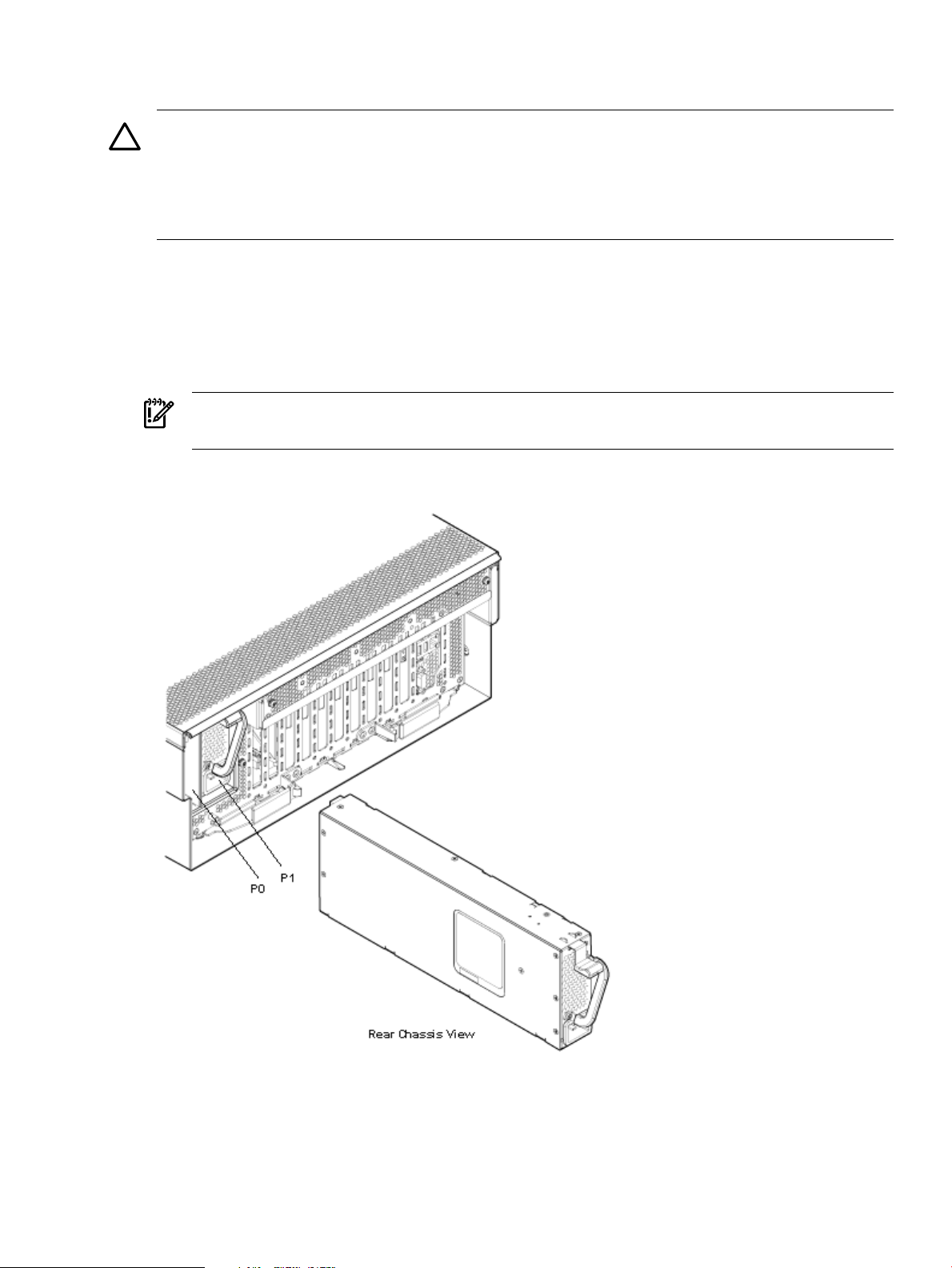
supply is identified as P0, and the second hot-swappable power supply is identified as P1
(Figure 3-3).
CAUTION: When a second power supply is not used, the empty power supply slot must remain
covered with the supplied metal filler panel. Failure to observe this caution can result in damage
due to overheating.
Install the hot-swappable power supply into the server before attaching the new power cord.
Failure to observe this caution can result in damage to the server.
Installing a Hot-Swappable Power Supply
To install a hot-swappable power supply on the front of the server, follow these steps:
1. Remove the metal filler panel if necessary.
2. Support the power supply with both hands, and slide it into the empty slot until it clicks
into place (Figure 3-3).
IMPORTANT: Ensure the power supply is flush with the adjacent power supply or metal
filler panel.
Figure 3-3 Installing a Hot-Swappable Power Supply
Removing and Replacing Hot-Swappable Disk Drive Fillers
There are disk drive fillers installed on the front of the server for all slots that do not contain a
disk drive.
Installing Additional Components 59
Page 60

IMPORTANT: For cooling purposes, always leave disk drive fillers in slots that do not contain
a disk drive.
Removing a Hot-Swappable Disk Drive Filler
To remove a hot-swappable disk drive filler, follow these steps:
1. Squeeze the tabs on the front of the filler to release it from the slot in the drive bay.
2. Pull gently until the filler slides out of the chassis.
Replacing a Hot-Swappable Disk Drive Filler
To replace a hot-swappable disk drive filler, follow these steps:
1. Orient the disk drive filler so that the release tab is on the left side of the filler and the airflow
holes are on the right side of the filler.
2. Insert the filler into the slot guides, and slide the filler into the slot until it clicks into place
and is fully seated.
Installing a Hot-Pluggable Disk Drive
There are eight hot-pluggable disk drives located in the front of the server. You can replace the
hot-pluggable disk drives using the procedures in this section when the server power is on or
off.
CAUTION: Drives are loaded in the factory, starting with number 8, working from right to left
and bottom to top. If you have never changed your SAS configuration before, you can safely
move SAS devices downwards as a block. If you have bays 6, 7, and 8 occupied you can move
them down to bays 1, 2, and 3 without having the hardware paths change during a cold-install
or recovery while the system is shut down, but you must move the disks in order and you cannot
rearrange them. For example, you can move bay 6 to 1, 7 to 2, and 8 to 3. After doing this you
can safely populate the SAS enclosure from bay 4 onwards. The same procedure can be performed
on bays 9 to 16.
CAUTION: A hot-pluggable device may require interaction with the operating system before
you can safely remove it from or install it into the server. Verify that the operating system supports
removing and replacing disk drives while the operating system is running. If the operating
system does not support this feature, shut down the operating system before attempting this
procedure. Failure to observe this caution can result in system failure.
TIP: When you receive an HP Integrity rx3600 or HP Integrity rx6600 server from HP, if you
ever plan to add other SAS devices into the system, you should consider moving the SAS devices
so they start in bay 1 going upwards instead of Bay 8 going downwards.
Installing a Hot-Pluggable Disk Drive
NOTE: The replacement disk drive must have the same product number as the disk drive that
you replace.
To install a hot-pluggable disk drive, follow these steps:
1. Use Figure 3-5 to determine the next available disk drive installation slot.
2. Remove the disk drive filler if required. See “Removing a Hot-Swappable Disk Drive Filler”
(page 60).
60 Installing the System
Page 61

NOTE: Save the disk drive filler for future use. For cooling purposes, always place disk
drive fillers in slots that do not contain a disk drive.
3. Insert the hot-pluggable disk drive into the slot guides, and slide the drive into the slot until
it seats into the socket on the disk backplane.
4. Close the drive ejector handle by pushing it inward until it clicks into place.
Figure 3-4 Installing a Hot-Pluggable Disk Drive
Figure 3-5 Disk Drive Slot IDs
Installing Additional Components 61
Page 62

Installing a PCI/PCI-X/PCIe Card
123456789
10
11
12
Figure 3-6 shows the PCI/PCI-X/PCIe slot identification and card divider locations.
NOTE: Slots one through eight are full-length; slots nine and ten are short-length.
Figure 3-6 PCI/PCI-X Slot Identification and Card Divider Locations
1
Slot 1
2
Slot 2
3
Slot 3
5
Slot 5
6
Slot 6
7
Slot 7
Slot 8Slot 4
9
Slot 9
10
Slot 10
11
Core I/O Board Slot
1284
PCI/PCI-X/PCIe Card
Dividers
PCI/PCI-X/PCIe Configurations
The section contains the following topics:
• “PCI/PCI-X IOBP” (page 63)
• “PCI/PCI-X/PCIe IOBP” (page 63)
• “Shared Slots” (page 63)
62 Installing the System
Page 63

PCI/PCI-X IOBP
The following describes configuration requirements for slots one through ten on the PCI/PCI-X
I/O backplane:
• PCI-X slots 1 and 2 are reserved for use by the core I/O cards SAS core I/O card in slot 1 and
Gigabit Ethernet LAN core I/O card in slot 2. Slots 1 and 2 are not hot-pluggable. Install only
supported PCI-X SAS and LAN core I/O cards in slots 1 and 2.Depending upon the number
and type of SAS core I/O cards installed on the system, the Gigabit Ethernet LAN core I/O
card may be installed in slot 10.
• Slots 3 and 4 are nonshared slots. The maximum speed for cards in slots 3 and 4 is PCI-X
266 MHz.
• Slots 5 and 6 are nonshared slots. The maximum speed for cards in slots 5 and 6 is PCI-X
133 MHz,
• Slots 7 and 8 are shared slots, and slots, 9 and 10 are shared slots. These four slots are limited
by bus mode or frequency-related incompatibilities. See “Shared Slots” (page 63) for more
information.
PCI/PCI-X/PCIe IOBP
The following describes configuration requirements for slots one through ten on the
PCI/PCI-X/PCIe I/O backplane:
• PCI-X slots 1 and 2 are reserved for use by the core I/O cards SAS core I/O card in slot 1 and
Gigabit Ethernet LAN core I/O card in slot 2. Slots 1 and 2 are not hot-pluggable. Install only
supported SAS and LAN core I/O cards in slots 1 and 2. Depending upon the number and
type of SAS core I/O cards installed on the system, the Gigabit Ethernet LAN core I/O card
may be installed in slot 10.
• Slots 3 and 4 are swtiched PCIe x8. PCIe SAS core I/O is installed in slots 3 and 4 on the
PCI/PCI-X/PCIe IOBP.
• Slots 5 and 6 are nonswitched PCIe x8.
• Slots 7 and 8 are nonshared slots. The maximum speed for cards in slots 7 and 8 is PCI-X
133 MHz.
• Slots 9 and 10 are shared slots. These two slots are limited by bus mode or frequency-related
incompatibilities.
IMPORTANT: Slots 9 and 10 on the PCI/PCI-X/PCIe I/O backplane have the same
configuration limitations as slots 9 and 10 on the PCI/PCI-X/ I/O backplane. See “Shared
Slots” (page 63) for more information.
Shared Slots
Shared slots have card compatibility restrictions. If one of the shared slots is occupied, the card
added to the second slot is limited by the configuration of the occupied slot. If the new card has
a slower capability than the current bus configuration, it fails. If the new card has a faster capability
than the current bus configuration, it only runs at the slower bus mode and frequency of the
current bus configuration.
The following are common configuration scenarios for cards that use shared slots. These examples
also apply to slots 9 and 10 because they are shared (both use a common bus).
1. If there is a PCI-X 66 MHz card in slot 7, and you hot-plug insert a PCI 33 MHz card into
slot 8, the operation fails. The new PCI 33 MHz card does not initialize and the slot powers
down because youcannot change bus speed during hot-pluggableoperations. The new card
has a slower bus speed than the current card.
Installing Additional Components 63
Page 64

NOTE: If the server is rebooted in the new configuration, both cards initialize to run at
PCI 33 MHz. This is because the system firmware can only change the bus capability down
to the lowest common value.
2. If there is a PCI 33 MHz card in slot 7, and you hot-plug insert a PCI-X 66 MHz card into
slot 8, the new card works but it runs at PCI 33 MHz.
3. If the server is powered off and you insert a PCI 33 MHz card into slot 7 with a PCI-X 66
MHz card is installed in slot 8), then both cards run at PCI 33 MHz when the server powers
up.
Table 3-2 lists the PCI/PCI-X card slot frequency and bus mode compatibility for shared slots.
Table 3-2 PCI/PCI-X Card Slot Frequency and Bus Mode Compatibility for Shared Slots
Cards to be InstalledCurrent PCI Bus
Mode and
Frequency for the
Card in a Shared
Slot
PCI 33 MHz
Compatible
2
Compatible
New card
running at PCI
33
2
Compatible
New cardrunning
at PCI 33
2
Compatible
New cardrunning
at PCI 33
2
1
PCI-X 266PCI-X 133PCI-X 66PCI 66PCI 33
Compatible
New cardrunning
at PCI 33
2
PCI 66 MHz
PCI-X 66 MHz
1 The conditions described in this table apply only to shared slots 7, 8, 9, and 10. Slots 1, 2, 3, 4, 5, and 6 are not shared
slots.
2 Compatible: card is accepted and runs at the frequency shown.
3 Incompatible-frequency: card does not work. The new card does not initialize and powers down due to frequency
mismatch.
4 Incompatible bus: Carddoes not work. The new card doesnot initialize and powers down due to bus mode mismatch.
Incompatible
frequency
Incompatible
frequency
Offline Installation of a PCI Card
Ensure that you install the proper drivers for PCI/PCI-X/PCIe cards after you complete the server
installation and power on the server.
To install a PCI/PCI-X/PCIe card with the power off, follow these steps:
1. Remove the top cover from the chassis. See “Removing the Top Cover” (page 56).
2. Select an empty slot that is appropriate for the card you are installing. To locate an appropriate
slot, see “PCI/PCI-X/PCIe Configurations” (page 62) and Figure 3-6 for more information.
3. Open the MRL.
a. Press the indentation on the MRL to release it from the chassis wall.
b. Lift the edge of the MRL and rotate it upward 90 degrees until it rests against the chassis
wall and the PCI/PCI-X/PCIe card bulkhead filler is fully exposed.
4. Remove the PCI/PCI-X/PCIe bulkhead filler.
2
3
3
Compatible
New card
running at PCI
66
Incompatible
4
bus
Compatible
New cardrunning
at PCI 66
Compatible
New cardrunning
at PCI-X 66
2
2
Compatible
New cardrunning
at PCI 66
Compatible
New cardrunning
at PCI-X 66
2
2
Compatible
New cardrunning
at PCI 66
Compatible
New cardrunning
at PCI-X 66
2
2
64 Installing the System
Page 65

5. Insert the PCI/PCI-X/PCIe card into the empty slot and exert firm, even pressure to seat the
card in the slot.
CAUTION: Ensure that you fully seat the card into the slot or the card can fail after power
is reapplied to the slot.
6. Connect all internal and external cables to the PCI/PCI-X card.
7. Close the MRL.
a. Rotate the MRL downward 90 degrees.
b. Push the edge of the MRL down until it clicks into place on the PCI/PCI-X/PCIe card
bulkhead.
8. Close the gate latch to secure the end of the card if it is full length.
9. Replace the top cover. See “Replacing the Top Cover” (page 57).
Removing and Replacing the Memory Carrier Assembly
The memory carrier assembly encloses the system DIMMs. There are two different memory
carrier assemblies available for the server:
• 8-DIMM memory carrier assembly
• 24-DIMM memory carrier assembly
The 8- and 24-DIMM memory carrier assemblies have two sides, 0 and 1, each of which contain
a memory board. System DIMMs seat onto the memory boards.
Table 3-3 lists the supported memory carrier assembly configurations.
Table 3-3 Supported Memory Carrier Assembly Configurations
WARNING! Ensure that the system is powered off and all power sources have been disconnected
from the server prior to moving DIMMs.
Voltages are present at various locations within the server whenever an ac power source is
connected. This voltage is present even when the main power switch is in the off position.
Failure to observe this warning can result in personal injury or damage to equipment.
CAUTION: Observe all ESD safety precautions before attempting this procedure. Failure to
follow ESD safety precautions can result in damage to the server.
Removing the Memory Carrier Assembly
To remove the memory carrier assembly, follow these steps:
Memory Boards InstalledMemory Carrier Configuration
Two 4-DIMM memory boards8-DIMM memory carrier
Two 12-DIMM memory boards24-DIMM memory carrier
Installing Additional Components 65
Page 66

1. Unlatch the cover release lever on the top cover and remove the memory carrier assembly
cover. See “Removing the Memory Carrier Assembly Cover” (page 57).
NOTE: You do not need to fully remove the top cover to service this component; however,
the top cover release lever must be open.
2. Press the button located in the center of the memory carrier assembly to release the extraction
handles (Figure 3-7).
CAUTION: Manipulate the extraction handles with care. Failure to observe this caution
can result in damage to the extraction handles.
3. Pull up on the extraction handles and rotate them outward 90 degrees (Figure 3-7). The
handles latch into the open position with an audible click.
4. Lift the memory carrier assembly out of the chassis (Figure 3-7).
NOTE: To avoid damage to the handles, HP recommends rotating the handles inward and
snapping them into place when servicing the system DIMMs, or any time the carrier is out
of the chassis. Before replacing the memory carrier, press the button to release the extraction
handles. Use the handles to replace the memory carrier into the chassis.
Figure 3-7 Removing and Replacing the Memory Carrier Assembly
Replacing the Memory Carrier Assembly
CAUTION: Ensure that the processor board assembly is fully seated before you replace the
memory carrier assembly. The processor board assembly access door must be flush with the
front bezel.
To replace the memory carrier assembly, follow these steps:
1. Ensure the extraction handles are positioned in the outward, unlocked position.
2. Align the memory carrier assembly with the front and rear chassis guide slots.
66 Installing the System
Page 67

NOTE: Assembly side 0 is on the left, and assembly side 1 is on the right as viewed from
the front of the chassis.
3. Slide the memory carrier assembly into the chassis until it begins to seat into the socket
located on the processor board.
CAUTION: Do not apply excessive force when closing the extraction handles and seating
the memory carrier assembly into the socket on the processor board. Manipulate the extraction
handles with care. Failure to observe these cautions can result in damage to the extraction
handles and other server components.
4. Rotate the extraction handles inward and press the handles straight down until they snap
into the locked position.
5. Replace the memory carrier assembly cover and latch the top cover release lever closed. See
“Replacing the Memory Carrier Assembly Cover” (page 58).
Installing System Memory DIMMs
System memory or DIMMs are located on a pair of memory boards inside the memory carrier
assembly.
WARNING! Ensure that the system is powered off and all power sources have been disconnected
from the server prior to performing this procedure.
Voltages are present at various locations within the server whenever an ac power source is
connected. This voltage is present even when the main power switch is in the off position.
Failure to observe this warning can result in personal injury or damage to equipment.
CAUTION: Observe all ESD safety precautions before attempting this procedure. Failure to
follow ESD safety precautions can result in damage to the server.
Figure 3-7 (page 66) shows the memory carrier assembly removed from the chassis.
Figure 3-8 shows the memory carrier with the side cover removed.
Figure 3-8 Memory Carrier Assembly with Side Cover Removed
Installing Additional Components 67
Page 68

Memory Installation Conventions
Before installing memory, read and understand the following memory installation conventions:
• Supported DIMM sizes and memory configurations
• DIMM load order
• DIMM slot IDs
Supported DIMM Sizes and Memory Configurations
The standard server configuration includes an 8-DIMM memory carrier which contains two
4-DIMM memory boards. An optional, high-capacity memory configuration is also available: a
24-DIMM memory carrier containing two 12-DIMM memory boards.
System DIMMs seat onto the memory boards. The minimum server configuration requires at
least one memory pair in the 8-DIMM memory carrier, and one memory quad (group of four
DIMMs) in the 24-DIMM memory carrier.
The following are the supported DIMM sizes for the server:
• 512 MB
• 1 GB
• 2 GB
• 4 GB
Table 3-4 lists the supported memory configurations for the server.
Table 3-4 Supported Memory Configurations
Maximum Memory
Configuration
32 GB (eight 4 GB DIMMs)2-GB (one pair: two 1-GB
96 GB (24x4 GB DIMMs)2 GB (one quad: four 512
8-DIMM memory carrier
(standard)
24-DIMM memory carrier
(optional, high-capacity)
Memory Boards InstalledMemory Carrier Type
Two 4-DIMM memory
boards
Two 12-DIMM memory
boards
Minimum Memory
Configuration
DIMMs)
MB DIMMs)
Memory Load Order
When installing memory, use a minimum of one pair in the 8-DIMM memory carrier, and one
quad in the 24-DIMM memory carrier, of like-sized DIMMs. Insert additional DIMMs into the
memory carriers in the next available pair or quad, in order of capacity from largest to smallest.
Install DIMMs into the appropriate slots on the memory carrier board; each slot has a unique
ID. Use Figure 3-9 and Figure 3-10 to determine where to install DIMMs on the memory carrier
board.
CAUTION: Do not mix DIMM sizes or types within a pair or quad. Load DIMM pairs and quads
in order of capacity from largest to smallest. For example, if you have a quad of 2 GB DIMMs
and a quad of 1 GB DIMMs, install the quad of 2 GB DIMMs first.
Failure to observe these cautions results in system degradation or failure
8-DIMM Memory Carrier Load Order The 8-DIMM memory carrier has two sides labeled side
0 and side 1, each of which contains a memory carrier board. The 8-DIMM memory carrier can
contain one to four pairs of memory. Pairs of memory are divided equally between the two sides
of the memory carrier. For example, if you have two pairs of memory to install, load two DIMMs
in slots 0A and 0B of side 0, and load two DIMMs in slots 0A and 0B of side 1.
Table 3-5 lists the 8-DIMM memory carrier load order.
68 Installing the System
Page 69

Table 3-5 8-DIMM Memory Carrier Load Order
Slot IDMemory Carrier SidePair Number
0A; 0BSide 01
0A; 0BSide 12
1A; 1BSide 03
1A; 1BSide 14
The DIMM slot IDS are the same for both 8-DIMM memory carrier boards. Unique slots are
identified within the carrier by the side in which they reside. For example, slot 0A is identified
as slot 0A, side 0; or slot 0A, side 1.
Figure 3-9 shows the DIMM slot IDs for the 8-DIMM memory carrier board.
Figure 3-9 8-DIMM Memory Carrier Board Slot IDs
24-DIMM Memory Carrier Load Order The 24-DIMM memory carrier has two sides, labeled
side 0 and side 1, each of which contains a memory carrier board. The 24-DIMM memory carrier
can contain up to six quads of memory. DIMM quads are loaded in order of size from largest to
smallest capacity.
DIMM quads are loaded in a certain way to balance the memory capacity between the two sides
of the memory carrier, startingwith side 0. If you have more than two quads ofmemory to install,
load the first quad into slots 0A-0D of side 0, and load the second quad into slots 0A-0D of side
1. For the third and remaining quads of memory see “Memory Loading Rules and Guidelines”
(page 70).
The DIMM slot IDS are the same for both 24-DIMM memory carrier boards. Unique slots are
identified within the carrier by the side in which they reside. For example, slot 0A is identified
as slot 0A, side 0; or slot 0A, side 1.
Figure 3-10 shows the DIMM slot IDs for the 24-DIMM memory carrier board.
Installing Additional Components 69
Page 70

Figure 3-10 24-DIMM Memory Carrier Board Slot IDs
Memory Loading Rules and Guidelines
Use the following rules and guidelines when installing memory:
• Install DIMMs in pairs for the 8-DIMM memory carrier and quads in the 24 DIMM memory
carrier.
• Ensure that all DIMMs within a pair or quad are identical.
• Install pairs or quads in order of capacity from largest to smallest. For example, install all 2
GB quads before 1 GB or smaller quads, and install all 1 GB quads before 512 MB quads.
• Side 0 must have equal or greater memory capacity than side 1.
• Install DIMM pairs or quads based on the following rules:
1. Load pairs or quads into the memory carrier in order, starting with slot 0 and ending
with slot 2.
2. Install the first pair or quad in side 0.
3. Install the second pair or quad in side 1.
4. For the remaining pairs or quads:
a. If both sides of the memory carrier contain the same capacity of memory, install
the next pairs or quad in side 0.
b. If side 0 contains more memory capacity, even though it may have less DIMMs
than side 1, install the next pair or quad in side 1.
c. If side 1 is full, install the remaining pairs or quads in side 0.
Table 3-6 shows several examples of proper memory carrier loading order.
70 Installing the System
Page 71

NOTE: The number in parenthesis indicates the order in which the quads are loaded.
Table 3-6 24-DIMM Memory Carrier Loading Examples
Memory Carrier Side 1Memory Carrier Side 0Quad Slot IDsQuad Number
Example 1
2 GB (2)2 GB (1)0A 0B 0C 0D0
1 GB (4)1 GB (3)1A 1B 1C 1D1
512 MB (6)512 MB (5)2A 2B 2C 2D2
Example 2
1 GB (2)2 GB (1)0A 0B 0C 0D0
1 GB (3)512 MB (4)1A 1B 1C 1D1
512 MB (5)2A 2B 2C 2D2
Example 3
1 GB (2)2 GB (1)0A 0B 0C 0D0
512 MB (3)1A 1B 1C 1D1
512 MB (4)2A 2B 2C 2D2
Example 4
Installing Memory
IMPORTANT: You must pull the ac power plugs on the server every time you modify the
DIMMs. If you do not pull the ac power plugs, the system does not display the correct DIMM
information.
To install memory, follow these steps:
1. Unlatch the cover release lever on the top cover and remove the memory carrier assembly
cover. See “Removing the Memory Carrier Assembly Cover” (page 57).
NOTE: You do not need to fully remove the top cover to service this component; however,
the top cover release lever must be open.
2. Remove the memory carrier assembly. See “Removing the Memory Carrier Assembly”
(page 65).
512 MB (2)2 GB (1)0A 0B 0C 0D0
512 MB (3)512 MB (5)1A 1B 1C 1D1
512 MB (4)512 MB (6)2A 2B 2C 2D2
Installing Additional Components 71
Page 72

NOTE: To avoid damage to the handles, HP recommends rotating the handles inward and
snapping them into place when servicing the system DIMMs or any time the carrier is out
of the chassis. Before replacing the memory carrier, press the button to release the extraction
handles. Use the handles to replace the memory carrier into the chassis.
3. Complete the following memory installation prerequisite tasks before installing the memory:
a. Determine the DIMM load order as appropriate for the 8-DIMM or 24-DIMM memory
carrier. For more information, see “Memory Load Order” (page 68).
b. Use Figure 3-9: “8-DIMM Memory Carrier Board Slot IDs” (page 69), or Figure 3-10:
“24-DIMM Memory Carrier Board Slot IDs” (page 70), to determine the DIMM slots
to populate.
c. Read, understand, and follow the general guidelines to install memory in the server.
See “Memory Loading Rules and Guidelines” (page 70).
4. Lay the memory carrier assembly on side 0 or side 1 so that the memory carrier side that
contains the DIMM slots that you will install DIMMs into faces upward (Figure 3-8 (page 67)).
5. Remove the memory carrier assembly side cover.
a. Press the release tabs (Figure 3-8 (page 67)) on both sides of the extraction handle release
button until the side cover releases from the top center of the assembly.
b. Rotate the side cover slightly to free the tabs from the retaining slots at the base of the
assembly (Figure 3-8 (page 67)).
c. Lift the side cover off the assembly.
6. Install the DIMMs (Figure 3-11).
a. Align the DIMM with the slot located on the memory board, and align the key in the
connector with the notch in the DIMM.
b. Push on each end of the DIMM firmly and evenly until it seats into the slot.
c. Ensure that the extraction levers are in the fully closed position.
Figure 3-11 Inserting a DIMM into the Memory Board Connector
72 Installing the System
Page 73

7. Replace the memory carrier assembly side cover.
a. Insert the side cover tabs into the retaining slots at the base of the assembly (Figure 3-8).
b. Insert the tabs (Figure 3-8) into the slots on both sides of the extraction handle release
button until the side cover snaps into place.
NOTE: To install DIMMs into slots on the other side of the memory carrier, turn the carrier
over to the opposite side (side 0 or side 1) and repeat the installation procedure.
8. Replace the memory carrier assembly and latch the top cover release lever. See “Replacing
the Memory Carrier Assembly” (page 66).
Removing and Replacing the Processor Board Assembly
The processor board assembly holds one or two dual-core Itanium processors and is located
beneath the disk drives and memory carrier assembly in the bottom service bay. The processor
board is mounted onto a removable carrier tray which is retained in the service bay by a hinged
access door.
WARNING! Ensure that the system is powered off and all power sources have been disconnected
from the server prior to performing this procedure.
Voltages are present at various locations within the server whenever an ac power source is
connected. This voltage is present even when the main power switch is in the off position.
Failure to observe this warning can result in personal injury or damage to equipment.
CAUTION: Observe all ESD safety precautions before attempting this procedure. Failure to
follow ESD safety precautions can result in damage to the server.
Removing the Processor Board Assembly
To remove the processor board assembly, follow these steps:
1. Unlatch the cover release lever on the top cover and remove the memory carrier assembly
cover. See “Removing the Memory Carrier Assembly Cover” (page 57).
NOTE: You do not need to fully remove the top cover to service this component; however,
the top cover release lever must be open. You must remove the memory carrier because it
attaches directly to the processor board.
2. Remove the memory carrier assembly. See “Removing the Memory Carrier Assembly”
(page 65).
3. Press the button located on top of the bezel directly in front of the memory carrier assembly
to release the processor board access door (Figure 3-12).
CAUTION: The processor board access door opens at a 30 degree angle. Do not force the
door to open to a greater angle. Failure to observe this warning results in damage to server
components.
4. Use the processor board assembly access door as a handle and gently slide the assembly out
of the chassis approximately six inches.
5. Grasp the handholds on the assembly carrier tray with both hands and carefully slide the
assembly out of the chassis (Figure 3-12).
Installing Additional Components 73
Page 74

Figure 3-12 Removing the Processor Board Assembly
Replacing the Processor Board Assembly
To replace the processor board assembly, follow these steps:
1. Align the edges of the processor board assembly with the assembly guides in the chassis.
2. Slide the processor board assembly into the chassis until it begins to seat into the socket
located on the midplane board.
3. Push the processor board access door upward until it locks into position.
4. Replace the memory carrier assembly. See “Replacing the Memory Carrier Assembly”
(page 66).
5. Replace the memory carrier assembly cover and latch the top cover release lever closed. See
“Replacing the Memory Carrier Assembly Cover” (page 58).
Installing a Dual-Core Processor
The server usesdual-core processors. Each processor contains two coresthat function as separate
processors. Dual-core processors double the processing power of the server while maintaining
the physical dimensions of a single processor.
74 Installing the System
Page 75
The server can contain one or two dual-core processors that provide the following configuration
options:
• 1P/2C (One processor/two cores)
• 2P/4C (Two processors/four cores)
WARNING! Ensure that the system is powered off and all power sources have been disconnected
from the server prior to performing this procedure.
Voltages are present at various locations within the server whenever an ac power source is
connected. This voltage is present even when the main power switch is in the off position.
Failure to observe this warning can result in personal injury or damage to equipment.
CAUTION: Intel Montvale processors cannot be intermixed with similar Montecito processors.
Processor speed and cache size must be identical for all processors in a system. Whether
upgrading, replacing or adding an additional processor, to ensure compatibility use processors
with identical part numbers.
Failure to observe this caution results in performance degradation or system failure.
CAUTION: Observe all ESD safety precautions before attempting this procedure. Failure to
follow ESD safety precautions can result in damage to the server.
Processor Load Order
The server can have up to two dual-core processors on the processor board. The slots on the
processor board are labeled Module 0 and Module 1.
Table 3-7 lists the processor load sequence.
Table 3-7 Processor Load Order
Required Tools
To install processors, use the processor install tool fastened to the processor board.
Installing a Dual-Core Processor
To install a dual-core processor, follow these steps:
1. Remove the memory carrier assembly cover. See “Removing the Memory Carrier Assembly
Cover” (page 57).
NOTE: You do not need to fully remove the top cover to service this component; however,
the top cover release lever must be open.
SlotDual-Core Processor
Module 01
Module 12
2. Remove the memory carrier assembly. See “Removing the Memory Carrier Assembly”
(page 65)
NOTE: You must remove the memory carrier because it attaches directly to the processor
board.
3. Remove the processor board assembly. See “Removing the Processor Board Assembly”
(page 73).
Installing Additional Components 75
Page 76

4. Open the processor cage (Figure 3-13).
a. Grasp the processor cage handle and rotate the handle upward.
b. Use the handle to rotate the cage closure 90 degrees toward the front of the assembly
until it stops.
IMPORTANT: Ensure the processor slot is entirely exposed. The processor must clear the
cage closure for proper installation.
5. Locate the appropriate processor slot (Module 0 or Module 1) to install the processor into
(Figure 3-13).
6. Remove the plastic airflow blocker covering the processor slot.
7. Remove the protective dust cover from the processor socket.
8. Ensure that the cam on the processor socket lock is in the unlocked, counterclockwiseposition.
The zero insertion force (ZIF) socket for the processor is locked and unlocked by half of a
full turn of the processor install tool. Rotate the cam counterclockwise 180 degrees (half
turn) unlocks the socket. A clockwise 180 degree rotation locks the socket.
CAUTION: Attempting to turn the locking mechanism more than 180 degrees can severely
damage the socket.
9. Remove any protective packaging from the processor.
NOTE: Protective covers are installed to protect connector pins. Save the covers for future
use.
10. Inspect the processor pins and verify that the pins are not bent.
11. Align the alignment holes on the processor with the alignment posts on the processor cage,
and carefully lower the processor onto the processor socket (Figure 3-14).
CAUTION: Do not press the processorinto the socket. When properly aligned, the processor
pins seat into the socket. No additional pressure is required. You can damage pins if too
much pressure is applied.
12. Lock the processor into the socket on the processor board (Figure 3-14).
a. Unfasten the processor install tool (2.5-mm driver) from the tool holder on the processor
board.
b. Insert the processor tool into the hole that runs down the side of the heatsink.
c. Rotate the processor tool clockwise 180 degrees.
CAUTION: Attempting to turn the locking mechanism more than 180 degrees can
severely damage the socket.
d. Refasten the processor install tool to the tool holder on the processor board.
13. Reconnect the processor power cable into the connector cable that attaches directly to the
processor board.
14. Close the processor cage (Figure 3-13).
a. Grasp the processor cage handle and rotate the cage closure inward toward the rear of
the assembly until it is completely closed.
b. Push the handle down until it is flush with the cage.
15. Replace the processor board assembly. See “Replacing the Processor Board Assembly”
(page 74).
16. Replace the memory carrier assembly. See “Replacing the Memory Carrier Assembly”
(page 66).
76 Installing the System
Page 77

17. Replace the memory carrier assembly cover and latch the top cover release lever closed. See
“Replacing the Memory Carrier Assembly Cover” (page 58).
Figure 3-13 Processor Board Assembly (Front View)
Figure 3-14 shows the power connectors, the processor lock / unlock mechanism location and
the alignment holes. One processor is installed in the illustration.
Figure 3-14 Processor Alignment Holes and Lock/Unlock Mechanism
Installing Additional Components 77
Page 78

Installing the Server into a Rack or Pedestal Mount
This section provides instructions on how to install the server into a rack or a pedestal mount.
This section addresses the following topics:
• “Installing the Server into a Rack” (page 78)
• “Installing the Server into a Pedestal Mount” (page 78)
Installing the Server into a Rack
The following information describes how to install the server into an HP rack or an approved
non-HP rack.
HP Rack
HP servers that are installed into racks are shipped with equipment mounting slides. An
installation guide comes with each set of slides: HP 3-7U Quick Deploy Rail System Installation
Instructions for HP Products. Follow the steps in this installation guide to determine where and
how to install the server into the rack.
The following are additional instructions for installing the HP Integrity rx3600 server into the
rack:
1. The cable management arm (CMA) is factory configured to mount on the left side of the
server as viewed from the rear of the chassis. You must switch the CMA from a left to a
right-mount configuration. The CMA is mounted on the right side of the server to ensure
easy removal of the power supplies.
2. Remove two T25 screws with the orange tags from the server bezel; one screw from the
same location on each side of the server. The screws are located behind the pull handles.
3. Remove the large orange screws from the rear of the rack located on the left and right server
slide rails. The server will not slide forward if these screws are not removed.
Non-HP Rack
The guide Mounting in non-HP racks enables you to evaluate the installation of HP equipment
into non-HP racks. Use this guide when you need to qualify whether you can install, maintain,
and service any HP equipment in a non-HP rack.
The guide is located on the Web at:
http://www.hp.com/racksolutions
Select mounting information from the menu, then select Mounting in non-HP racks.
Installing the Server into a Pedestal Mount
The server ships with a pedestal mount if you order the rackless configuration option. The
pedestal mount is packaged in a separate carton that is attached to the server carton.
To change the server from a rack mount to a rackless configuration, you need a Server Rackless
Mount Kit. The rackless mount kit comes with the HP Integrity rx3600 Rack to Pedestal Conversion
Guide. Follow the steps in the HP Integrity rx3600 Rack to Pedestal Conversion Guide to attach the
pedestal mount to the server.
Connecting the Cables
This section provides information on the cables that power the server and provide LAN
connectivity for the server.
This section addresses the following topics:
• “AC Input Power” (page 79)
• “LAN” (page 80)
78 Installing the System
Page 79

AC Input Power
The server can receive ac input from two different ac power sources. If two separate power
sources are available, you can plug the server into the separate power sources, increasing system
reliability if one power source fails. The power receptacles are located at the rear of the chassis.
They are labeled PWR 0 and PWR 1.
You can install a maximum of two bulk power supplies (BPS) in the server. Installing two BPSs
in the server provides 1+1 redundancy, meaning that if one BPS fails, there is still enough power
supplied to the server for it to remain operational. You must promptly replace the failed BPS to
restore 1+1 functionality.
A minimum of one BPS is required to power the server. There is no 1+1 capability if only one
BPS is present.
Power States
The server has three power states:
• standby power
• full power
• off
To get to standby power state plug the power cord into the appropriate receptacle on the rear
of the chassis. The front panel power button is not turned on.
Full power occurs when the power cord is plugged into the appropriate receptacle and either
the power is activated through the iLO 2 MP PC command, or the power button is activated.
In the off state, the power cords are not plugged in.
Table 3-8 lists the server power states.
Table 3-8 Power States
Power States
Power Cable
Plugged Into
Receptacle
Power Activated through the iLO 2 MP PC
Command; or Front Panel Power Button
Activated
ac Voltage
Applied
dc Voltage
Applied
NoYesNoYesStandby power
YesYesYesYesFull power
NoNoNoNoOff
NOTE: If the power restore feature is set to Always On through the iLO 2 MP PR command,
the server can automatically power on to the full power state.
Figure 3-15 shows the rear panel power receptacles and power supply LEDs.
Figure 3-15 Rear Panel Power Receptacles and Power Supply LEDs
Connecting the Cables 79
Page 80
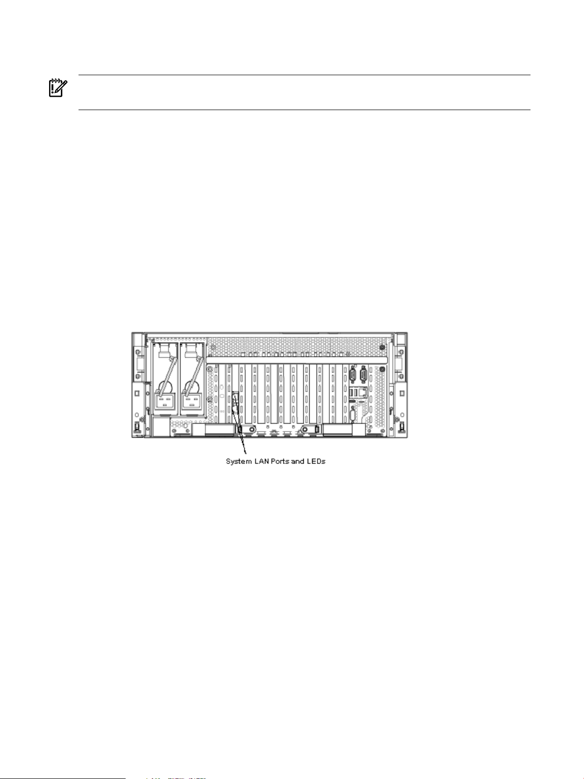
Applying Standby Power to the Server
To apply standby power to the server, follow these steps:
IMPORTANT: If the server has one BPS, plug the power cable into the receptacle labeled PWR
1.
1. Locate the appropriate receptacle on the rear of the chassis. Plug the power cord into the
receptacle.
2. Observe the following LEDs at two different intervals to ensure the server is in the standby
power state:
INTERVAL ONE After you plug the power cord into the server, the BPS flashes green and
an no light is present on the hard disk drives.
INTERVAL TWO Approximately 30 seconds later, the BPS is green and no light is present
on the hard disk drives. Standby power is now on.
LAN
The server has two LAN ports that can provide network connectivity.
Figure 3-16 shows the available LAN ports for the server.
Figure 3-16 Rear Panel LAN Ports
To enable general network connectivity for the server, follow these steps:
1. Obtain valid IP addresses for each LAN port you plan to activate.
2. Connect the LAN cable from an available LAN port to a live connection on the network.
Console Setup
Setting up the console involves the following:
1. Determining the physical access method to connect cables.There are two physical connections
to the Integrity iLO 2 MP:
• RS-232 serial port
• iLO 2 MP LAN port
2. Configuring the Integrity iLO 2 MP and assigning an IP address if necessary. Though there
are several methods to configuring the LAN, DHCP with DNS is the preferred one. DHCP
with DNS comes preconfigured with default factory settings, including a defaultuser account
and password. Other options include:
• ARP-Ping
• RS-232 serial port
80 Installing the System
Page 81

This section addresses the following topics:
• “Overview” (page 81)
• “Setup Checklist” (page 82)
• “Console Setup Flowchart” (page 82)
• “Preparation” (page 83)
• “Configuring the iLO 2 MP LAN Using DHCP and DNS” (page 85)
• “Configuring the iLO 2 MP LAN Using ARP Ping” (page 86)
• “Configuring the iLO 2 MP LAN Using the RS-232 Serial Port” (page 88)
• “Logging In to the iLO 2 MP” (page 89)
• “Additional Setup” (page 89)
Overview
A console is a tool consisting of display and input devices used to locally and remotely monitor
and control the server. The console enables interaction with the following manageability,
configuration, and diagnostic tools:
• Integrated Lights-Out 2 Management processor (iLO 2 MP). Provides a way to connect to
the server and perform administration or monitoring tasks for the server hardware. It controls
power, reset, and Transfer of Control (TOC) capabilities; provides console access; displays
and records system events; and displays detailed information about internal subsystems.
The iLO 2 MP is available whenever the system is connected to a power source, even if the
server main power switch is turned off.
NOTE: For more information on the integrated lights-out management processor, see the
HP Integrity Integrated Lights-Out 2 Management Processor Operations Guide.
• Extensible Firmware Interface (EFI). Provides an interface between the operating system
and the firmware. Use the EFI to configure options, such as the server boot order, before the
server loads an operating system.
Table 3-9 lists the elements required to start a console session.
Table 3-9 Elements Required to Start a Console Session
DescriptionConsole Element
ac power (standby power)
Console device
Console emulation software
1
The server must have ac power to provide console functionality. See
“Applying Standby Power to the Server” (page 80).
Includes the iLO 2 MP and console cable connectors.Server hardware components
Links the server console to the console device.Console cable
Provides display and input functionality using components such as
monitors, keyboards, and mouse devices.
Emulates the output from the server console and displays the output on
the console device screen.
Console Setup 81
Page 82

1
IMPORTANT: Windows 2003 Server places the video controller into a non-standard resolution with a refresh rate
of 55Hz. Some LCD monitors are not capable of rendering a screen with refresh rates lower than 60Hz. Use one of
the following methods to resolve this issue:
• Use a monitor capable of 55Hz refresh rates. Virtually all analog monitors and the majority of LCD monitors are
capable of this.
• Use a LAN-based client to remotely access the server's iLO2 Integrated Remote Console (vKVM) feature for the
installation.
Setup Checklist
Use the checklist in Table 3-10 to assist you with the console setup process.
Table 3-10 Setup Checklist
Standard and Advanced
XActionStep
Preparation1
Configure the iLO 2 MP LAN2
Log on to the iLO 2 MP3
Change default user name and
4
password
Advanced
1 For details on Advanced Pack Features see the HP Integrity iLO 2 MP Operations Guide.
Console Setup Flowchart
1. Determine access method to select and connect cables.
2. Determine LAN configuration method and assign IP address
if necessary.
There are three methods to configure theLAN for iLO 2 MPaccess:
• DHCP with DNS
• ARP Ping
• RS-232 serial port
Log in to the iLO 2 MP from a supported Web browser or
command line using the default user name and password.
Change the default user name and password on the administrator
account to your predefined selections.
Set up the user accounts if using the local accounts feature.Set up user accounts5
Set up the security access settings.Set up security access6
Access the host console using method of choice.Access the host console7
1
Activate advanced features by entering a license key.Activate Advanced Pack Features
Use this flowchart as a guide to assist in the console setup process.
82 Installing the System
Page 83

Figure 3-17 Console Setup Flowchart
Preparation
There are several tasks to perform before you can configure the iLO 2 MP LAN.
• Determine the physical access method to select and connect cables.
• Determine the iLO 2 MP LAN configuration method and assign an IP address if necessary.
Determining the Physical iLO 2 MP Access Method
Before you can access the iLO 2 MP, you must first determine the correct physical connection
method. The iLO 2 MP has a separate LAN port from the system LAN port. It requires a separate
Console Setup 83
Page 84

LAN drop, IP address, and networking information from that of the port used by the operating
4
1
2
3
5
6
7
8
9
10
11
system.
Figure 3-18 shows the server rear ports.
Figure 3-18 Server Rear Ports
1
iLO 2 MP RS-232 Serial
Port (DB-9F to DB-9F
cable)
Connected to emulation
5
VGA Port
(No iLO 2 MP access; EFI
only)
6
General Use Serial Port
9
Link and Activity LED
10
Standby Power
11
MP Self Test
terminal device (PC,
laptop, or ASCII
terminal)
2
USB 2.0 Ports
(any USB device)
3
BMC Heartbeat
4
MP Heartbeat
(Printers, etc.)
7
10 Base-T/100 Base-T
Mode LED
8
iLO 2 MP LAN Port
(10/100 LAN)
Table 3-11 lists the appropriate connection method, required connection components, and
connectors to the host console. Use this table to determine your physical connection method.
84 Installing the System
Page 85

Table 3-11 Physical Connection Matrix
Required Connection ComponentsConnection Method
RS-232 serial port
1. Host console
2. RS-232 serial port DB-9F to DB-9F cable
3. Emulation terminal device (for example, a PC, laptop, or ASCII terminal)
10/100 LAN cableLAN port
Determining the iLO 2 MP LAN Configuration Method
To access the iLO 2 MP through the iLO 2 MP LAN, the iLO 2 MP must acquire an IP address.
The way the iLO 2 MP acquires an IP address is dependent upon whether DHCP is enabled or
disabled on the server, and if DHCP and DNS services are available to the server. (See Table 3-12
for possible scenarios.)
Once you have determined the iLO 2 MP access, you must determine how you will configure
the iLO 2 MP LAN in order to acquire an IP address. There are three methods available.
• DHCP/DNS
• ARP Ping
• RS-232 serial port
Table 3-12 provides all the possible scenarios to consider. Use this table to help you select the
appropriate LAN configuration method to obtain an IP address.
Table 3-12 LAN Configuration Methods
DNSDHCP
LC command)
LAN Configuration MethodRS-232 Serial Port (MP
DHCPNoYesYes
DHCP or RS-232 serial portYesYesYes
ARP PingNoNoNo
ARP PingNoYesNo
ARP Ping or RS-232YesYesNo
RS-232 serial portYesNoYes
RS-232 serial port or ARP PingYesNoNo
Cannot set up the LAN. Reconsider your criteria.NoNoYes
Once you have determined how you will configure the iLO 2 MP LAN in order to acquire an IP
address, you must configure the iLO 2 MP LAN using the selected method.
Configuring the iLO 2 MP LAN Using DHCP and DNS
DHCP automatically configures all DHCP-enabledservers with IP addresses, subnet masks, and
gateway addresses. All HP Integrity entry class servers with the iLO 2 MP are shipped from the
factory with DHCP enabled.
HP recommends using the DHCP and DNS method to simplify access to the iLO 2 MP.
NOTE: You can use ARP Ping regardless of the status of DHCP unless an IP address has ever
been acquiredusing DHCP. Once an IP address is assigned using DHCP, ARP Ping is permanently
disabled.
When you use DHCP and DNS, you can connect to the iLO 2 MP by typing the default host name
in your browser rather than an IP address only if the following applies:
Console Setup 85
Page 86

• DHCP must be enabled (DHCP is enabled by default).
• You are using a DHCP server that provides the domain name.
• The primary DNS server accepts dynamic DNS (DDNS) updates.
• The primary DNS server IP address has been configured through the DHCP server.
IMPORTANT: You must know the DNS domain name, which is served out by the DHCP server,
unless it’s domain is local or the same domain.
To configure the iLO 2 MP using DHCP and DNS, follow these steps:
1. Obtain the factory-set host name from the iLO 2 MP Media Access Protocol (MAC) address
label on the server. The default host name is 14 characters long, consisting of the letters mp
followed by the 12 characters of the MAC address as in this example:
mp0014c29c064f
This address is assigned to the iLO 2 MP core IO board. The core IO board has a unique
MAC address that identifies the hardware on the network.
IMPORTANT: Make sure you obtain the MAC address to the core IO board and not the
MAC address to the server core LAN card.
2. Connect the LAN cable from the server to an active network port.
3. Apply ac power to the server.
4. Open a browser, telnet, or SSH client and enter the default host name. The default host name
is the letters mp followed by the 12 characters of the MAC address. The iLO 2 MP Log In
window opens.
5. Log in using the default user name and password.
CAUTION: When DHCP is enabled, the system is vulnerable to security risks because anyone
can access the iLO 2 MP until you change the default user name and password.
HP strongly recommends you assign user groups and rights before proceeding.
Configuring the iLO 2 MP LAN Using ARP Ping
NOTE: You can use ARP Ping regardless of the status of DHCP unless an IP address has ever
been acquiredusing DHCP. Once an IP address is assigned using DHCP, ARP Ping is permanently
disabled. Some DHCP server options can cause the apparent issuance of ARP Ping to the iLO 2
MP which will negate the DHCP/DDNS method.
The Address Resolution Protocol (ARP) and Packet Internet Grouper (Ping) utility uses ARP
packets to ping, or discover, a device on the local network segment. The IP address you assign
to the server must use the same network segment, or subnet, as the computer assigning the
address. ARP does not work across routed or switched networks.
Use the ARP Ping utility to assign a static IP address when you do not have access to the RS-232
serial port or when DHCP is not available.
86 Installing the System
Page 87

NOTE: ARP Ping operational issues:
• The PC and the server must be on the same physical subnet.
• When a new server is first booted, DHCP is automatically available (factory-set default);
but ARP Ping does not start for three minutes after the iLO 2 MP is booted. This applies to
every subsequent boot of the iLO 2 MP until an IP address is obtained by DHCP or has been
assigned by using the LC command.
• Upon successfully assigning an IP address using ARP Ping, DHCP is automatically disabled.
There are two methods to use the ARP Ping utility:
1. Connect a PC to the network that is on the same physical subnet as the server and run the
ARP Ping commands from the PC.
2. Locate an existing server on the network, log into it, and run the ARP Ping commands from
the server.
Table 3-13 lists the ARP Ping commands.
Table 3-13 ARP Ping Commands
DescriptionARP Command
arp -s
ping
This command assigns the IP address to the iLO 2 MP MAC address. This ARP table entry
maps the MAC address of the iLO 2 MP LAN interface to the static IP address designated for
that interface.
This command tests network connections. It verifies the iLO 2 MP LAN port is configured
with the appropriate IP address.
The following procedure explains how to use the ARP Ping utility using a PC that is connected
to the network that is on the same physical subnet as the server.
To configure a static IP address using the ARP Ping utility, follow these steps:
1. Obtain the iLO 2 MP MAC address. To set the IP address using ARP, you must know the
MAC address of the iLO 2 MP LAN. You can find the MAC address of the iLO 2 MP LAN
on a label on the server.
IMPORTANT: Make sure you obtain the MAC address to the iLO 2 MP LAN and not the
MAC address to the server core LAN.
2. Verify that an active LAN cable on the local subnet is connected to the iLO 2 MP LAN port
on the server.
3. Access a PC on the same physical subnet as the server.
4. Open a DOS window on the PC.
5. At the DOS prompt, enter arp -s to assign the IP address to the iLO MAC address.
Syntax
arp -s <IP address you want to assign to the iLO MAC address> <iLO 2 MAC address>
Example from Windows
arp -s 192.0.2.1 00-00-0c-07-ac-00
6. At the DOS prompt, enter ping followed by the IP address to verify that the iLO 2 MP LAN
port is configured with the appropriate IP address. The destination address is the IP address
that is mapped to the iLO MAC address. Perform this task from the PC that has the ARP
table entry.
Syntax
ping <IP address just assigned to the iLO MAC address>
Example from Windows
Console Setup 87
Page 88

ping 192.0.2.1
7. Use the IP address to connect to the iLO 2 MP LAN.
8. Use Web or telnet access to connect to the iLO 2 MP from a host on the local subnet and
complete the rest of the LAN parameter (gateway, subnet).
Configuring the iLO 2 MP LAN Using the RS-232 Serial Port
To configure the iLO 2 MP LAN using the RS-232 serial port, follow these steps:
IMPORTANT: Do not configure duplicate IP addresses on different servers within the same
network. The duplicate server IP addresses conflict and the servers cannot connect to the network.
The LC command enables you to configure an IP address, host name, subnet mask, and gateway
address.
IMPORTANT: Ensure you havea console connection through the RS-232 serial port or a network
connection through the LAN to access the iLO 2 MP and use the LC command.
To assign a static IP address using the LC command, follow these steps:
1. Ensure the emulation software device is properly configured. The terminal emulation device
runs software that interfaces with the server. The software emulates console output as it
would appear on an ASCII terminal screen and displays it on a console device screen. To
ensure the emulation software is correctly configured, follow these steps:
a. Verify that the communication settings are configured as follows:
• 8/none (parity)
• 9600 baud
• None (receive)
• None (transmit)
b. Verify that the terminal type is configured appropriately. Supported terminal types are:
• hpterm
• vt100
• vt100+
• vt-utf8
IMPORTANT: Do not mix hpterm and vt100 terminal types at the same time.
There are many different emulation software applications. Consult the help section of the
emulation software application for instructions on how to configure the software options.
2. Determine the required connection components, and the ports used to connect the server
to the console device.
3. Connect the cables from the appropriate ports to the server.
4. Start the emulation software on the console device.
5. Log in to the iLO 2 MP. See “Logging In to the iLO 2 MP” (page 89).
6. At the MP Main Menu, enter CM and press Enter to select command mode.
7. At the command mode prompt, enter LS and press Enter. The screen displays the default
LAN configuration values. Write down the default values, or log the information to a file.
You may need the information for future troubleshooting.
88 Installing the System
Page 89

8. Use the LC command to disable DHCP.
a. From the LC command menu, type D and press Enter.
b. Follow the instructions on the screen to change the DHCP status from Enabled to
Disabled.
c. Enter XD -R to reset the iLO 2 MP.
9. Use the LC command to enter information for the IP address, host, subnet mask, gateway
parameters, and so on.
10. Enter XD -R to reset the iLO 2 MP.
11. After the iLO 2 MP resets, log in to the iLO 2 MP again and enter CM at the MP:> prompt.
12. Enter LS to confirm that DHCP is disabled and display a list of updated LAN configuration
settings.
Logging In to the iLO 2 MP
To log in to the iLO 2 MP, follow these steps:
1. Access the iLO 2 MP using the LAN, RS-232 serial port, telnet, SSH, or Web method. The
iLO 2 MP login prompt displays.
2. Log in using the default the iLO 2 MP user name and password (Admin/Admin).
TIP: For security reasons, HP strongly recommends you modify the default settings during
the initial login session. See “Modifying User Accounts and Default Password” (page 89).
Following is the MP Main Menu:
iLO MP MAIN MENU:
CO: Console
VFP: Virtual Front Panel
CM: Command Menu
CL: Console Logs
SL: Show Event Logs
SMCLP: Server Management Command Line Protocol
HE: Main Menu Help
X: Exit Connection
See the HP Integrity Integrated Lights-Out 2 Management Processor Operations Guide for information
on the iLO 2 MP menus and commands.
When logging in using the local or remote RS-232 serial ports, the login prompt may not display
if another user is logged in through these ports. Use Ctrl-B to access the MP Main Menu and the
iLO 2 MP prompt (MP>).
Additional Setup
This section provides additional information to setup the iLO 2 MP.
Modifying User Accounts and Default Password
The iLO 2 MP comes preconfigured with default factory settings, including a default user account
and password. The two default user accounts on initial login are:
• All Rights (Administrator) level user:
login = Admin
password = Admin
• Console Rights (Operator) level user:
login = Oper
password = Oper
Console Setup 89
Page 90

Login and password are case sensitive.
TIP: For security reasons, HP strongly recommends you modify the default settings during the
initial login session.
Make the following changes using any of the iLO 2 MP user interfaces.
To modify default account configuration settings, follow these steps:
1. Log in as the administrator. You must log in as the administrator in order to modify default
user configuration settings
2. To modify default passwords:
a. Access the MP Main Menu.
b. Enter CM at the MP> prompt.
c. Enter UC at the MP:CM> prompt and follow the prompts to modify default passwords.
3. To setup user accounts:
a. Access the MP Main Menu.
b. Enter CM at the MP> prompt.
c. Enter UC at the MP:CM> prompt and follow the prompts to modify user accounts.
Setting Up Security
For greater security and reliability, HP generally recommends that iLO 2 MP management traffic
be on a separate dedicated management network and that only administrators be granted access
to that network. This not only improves performance by reducing traffic load across the main
network, it also acts as the first line of defense against security attacks. A separate network
enables administrators to physically control which workstations are connected to the network.
HP also strongly recommends you modify the default settings during the initial logon session
and determine the security access required and what user accounts and privileges are needed.
Create local accounts or use directory services to control user access. See “Modifying User
Accounts and Default Password” (page 89).
Security Access Settings
Determine the security access required and what user accounts and privileges are needed. The
iLO 2 MP provides options to control user access. Select one of the following options to prevent
unauthorized access to the iLO 2 MP:
• Change the default user name and password. See “Modifying User Accounts and Default
Password” (page 89)).
CAUTION: When DHCP is enabled, the system is vulnerable to security risks because
anyone can access the iLO 2 MP until you change the default user name and password.
HP strongly recommends you assign user groups and rights before proceeding.
• Create local accounts. You can store up to 19 user names and passwords to manage iLO 2
MP access. This is ideal for small environments such as labs and small-to-medium sized
businesses.
• Use directory services. Use the corporate directory to manage iLO 2 MP user access. This is
ideal for environments with a large number of frequently changing users. If you plan to use
directory services, HP recommends leaving at leastone local account enabled as an alternate
method of access.
90 Installing the System
Page 91

Accessing the Host Console
This section provides information on the different methods of accessing the host console of an
HP Integrity server.
This section addresses the following topics:
• “Accessing the iLO 2 MP With the Web Browser” (page 91)
• “Accessing the Host Console With the TUI - CO Command” (page 92)
• “Accessing the Host Console With vKVM - Integrated Remote Console” (page 93)
• “Accessing the Host Console with the SMASH SM CLP” (page 93)
• “Accessing the Graphic Console Using VGA ” (page 93)
Accessing the iLO 2 MP With the Web Browser
Web browser access is an embedded feature of the iLO 2 MP.
The iLO 2 MP has a separate LAN port from the system LAN port. It requires a separate LAN
drop, IP address, and networking information from that of the port used by the operating system.
IMPORTANT: Make sure you use the MAC address to the iLO 2 MP LAN and not the MAC
address to the server core LAN.
Before starting this procedure, you must have the following information:
• IP address for the iLO 2 MP LAN
• Host name (this is used when messages are logged or printed)
To interact with the iLO 2 MP through the Web GUI, follow these steps:
1. Open a Web browser and enter the host name or the IP address for the iLO 2 MP.
2. Log in using your user account name and password at the login page. (Figure 3-19).
Figure 3-19 Web Login Page
Accessing the Host Console 91
Page 92

3. Click Sign In. The Status Summary page (Figure 3-20) displays after login.
Function Tabs
Navigation Bar
Display Screen
Figure 3-20 Status Summary Page
Help
Accessing the Host Console With the TUI - CO Command
1. Select the Web interface functions by clicking the Function tabs at the top of the page. Each
function lists options in the Navigation Bar on the left side of the page.
2. Click an option link to display data in the Display screen; and click Refresh to update the
display.
3. Click the Remote Console tab. The remote console provides the following optionsto access
the console:
• A serial console that behaves similarly to the TUI of the following section
• The virtual KVM console
The iLO 2 MP Web interface has a robust help system. To launch iLO 2 MP help, click the Help
tab in the Display screen or click the ? at the top right corner of each page to display help about
that page.
This section provides the steps to access the host console using the text user interface (TUI).
To access the host console through the iLO 2 MP, follow these steps:
1. Log in using your user account name and password at the login page.
2. At the iLO 2 MP login prompt (MP>), enter the CO command to switch the console terminal
from theMP Main Menu to mirrored/redirected console mode. All mirrored datais displayed.
3. To return to the iLO 2 MP command interface, type Ctrl-B, or Esc and +.
92 Installing the System
Page 93

Accessing the Host Console With vKVM - Integrated Remote Console
For information on how to access the host console using the vKVM feature through the Integrated
Remote Console (IRC), see the HP Integrity Integrated Lights-Out 2 Management Processor Operations
Guide.
Accessing the Host Console with the SMASH SM CLP
For information on how to access the host console using the SMASH SM CLP, see the HP Integrity
Integrated Lights-Out 2 Management Processor Operations Guide.
Accessing the Graphic Console Using VGA
VGA is a method you can use to access the graphic console.
NOTE: You cannot access the iLO 2 MP using VGA.
This method requires three elements:
• Monitor (VGA connector)
• Keyboard (USB connector)
• Mouse (USB connector)
The graphic console output displays on the monitor screen.
IMPORTANT: The server console output does not display on the console device screen until
the server boots to the EFI Shell. Start a console session using the RS-232 serial port method to
view console output prior to booting to the EFI Shell or to access the iLO 2 MP. See “Configuring
the iLO 2 MP LAN Using the RS-232 Serial Port” (page 88).
To access the graphic console with VGA, follow these steps:
1. Perform preparation tasks.
2. Connect the cables. See your user service guide for specific port information.
a. Connect the monitor VGA cable to the appropriate VGA port on your server.
b. Connect the keyboard USB cable to the appropriate USB port on your server.
c. Connect the mouse USB cable to the appropriate USB port on your server.
3. Power on the server. The EFI Shell prompt displays.
Powering On and Powering Off the Server
This section provides information and procedures for powering off and powering on the server.
This section address the following topics:
• “Power States” (page 93)
• “Powering On the Server” (page 94)
• “Powering Off the Server” (page 95)
Power States
The server has three power states:
Standby power Plug the power cord into the appropriate receptacle on the rear of the
chassis; the front panel power button is not turned on.
Full power Full power occurs when you plug the power cord into the appropriate
receptacle, and either activate the power using the iLO 2 MP PC command,
or press the power button.
Off Unplug the power cords.
Table 3-14 lists the server power states.
Powering On and Powering Off the Server 93
Page 94

Table 3-14 Power States
Power States
Power Cable
Plugged into
Receptacle
Powered On With the iLO 2 MP PC
Command; or Front Panel Power Button
Pressed
NOTE: If the power restore feature is set to Always On through the iLO 2 MP PR command,
the server can automatically power on to the full power state.
Powering On the Server
Power on the server to full power using the following methods:
• iLO 2 MP PC command
• Power button
Powering On the Server Using the iLO 2 MP
NOTE: If the power restore feature is set to Always On through the iLO 2 MP PR command,
the server can automatically power on to the full power state.
AC Voltage
Applied
DC Voltage
Applied
NoYesNoYesStandby power
YesYesYesYesFull power
NoNoNoNoOff
To power on the server using the iLO 2 MP, follow these steps:
1. Plug all power cables into the receptacles on the rear panel of the server.
2. Initiate a console session and access the MP Main Menu.
3. Enter CM to enable command mode.
4. Enter PC to use the remote power control command.
5. Enter ON to power on the server, and enter YES when prompted to confirm the action.
6. Start the operating system. For more information see the operating system documentation.
Powering On the Server Manually
NOTE: If the power restore feature is set to Always On through the iLO 2 MP PR command,
the server may automatically power on to the full power state.
To manually power on the server, follow these steps:
1. Plug all power cables into the receptacles on the rear panel of the server.
2. Press the power button to start the server.
94 Installing the System
Page 95

Figure 3-21 rx3600 Power Button
Pow er But to n
3. Start the operating system. For more information see the operating system documentation.
Powering Off the Server
Power off the server using the following methods:
• iLO 2 MP PC command
• Power button
Powering Off the Server Using the iLO 2 MP
To power off the server using the iLO 2 MP, follow these steps:
1. Gracefully shut down the operating system. For more information see the operating system
documentation.
2. Initiate a console session and access the MP Main Menu.
3. Enter CM to enable command mode.
4. Use the remote power control command with the graceful shutdown option.
5. Enter OFF to power off the server, and enter YES when prompted to confirm the action.
IMPORTANT: The main dc voltage is now removed from the system; however, ac voltage
for standby power is still present in the server.
6. Unplug all power cables from the receptacles on the rear panel of the server.
Powering Off the Server Manually
To manually power off the server, follow these steps:
• A momentary push on the power button will gracefully shut down the operating system.
For more information see the operating system documentation.
IMPORTANT: The main dc voltage is now removed from the system; however, ac voltage
for standby power is still present in the server.
Core I/O Card Configuration
This section provides information on core I/O cards that need to be configured during installation.
This section addresses the following topics:
Core I/O Card Configuration 95
Page 96

• “Integrated RAID” (page 96)
• “HP 8 Internal Port SAS HBA (SAS Controller)” (page 96)
• “MPTUTIL Utility” (page 96)
• “DRVCFG Utility” (page 98)
• “CFGGEN Utility” (page 106)
• “Smart Array P400, P600 and P800 Controllers” (page 109)
• “SAUPDATE Utility” (page 110)
• “EBSU Utility” (page 113)
• “ORCA Utility” (page 116)
• “ACU Utility” (page 117)
Integrated RAID
Use Integrated RAID (IR) where either storage capacity, redundancy, or both of a RAID
configuration are required. Two components of IR are:
• Integrated Mirror (IM)
• Global Hot Spare
Integrated Mirror
The advantage of an IM is there is always a mirrored copy of the data. An IM provides data
protection for the system boot volume to safeguard critical information such as the operating
system on servers and high performance workstations. An IM supports two simultaneous
mirrored volumes, making an array, providing fault-tolerant protection for critical data. Typically,
one of these volumes is the boot volume. If a disk in an IM fails, the hot swap capability enables
the volume to be easily restored by replacing the failed disk. The firmware then automatically
re-mirrors to the replaced disk.
Global Hot Spare
Each SAS controller can have one global hot spare disk available to automatically replace a failed
disk in the one or two IM volumes configured on the controller. The hot spare makes the IM
array more fault tolerant. Up to two IM volumes are supported per SAS controller plus the hot
spare.
HP 8 Internal Port SAS HBA (SAS Controller)
The following information is provided to assist you in configuring the 8 Internal Port SAS HBA
controller during installation.
To flash firmware, use the MPTUTIL command. To configure and maintain the IR functionality
of the SAS controller on the HP Integrity server, use the drvdfg and cfggen EFI commands.
If you are scripting multiple devices, use thecfggencommand.
MPTUTIL Utility
The mptutil utility enables you to update the adapter flash memory with the EFI driver and
HBA firmware. New versions of these images are released periodically.
IMPORTANT: Do not store the files in this package on a SAS device. If you store these files on
a SAS device and the update fails, these files will not be accessible.
To update firmware, follow these steps:
96 Installing the System
Page 97

1. Insert the HP IPF Offline Diagnostics and Utilities CD in the drive and boot to the EFI Shell.
NOTE: You can also download the firmware image file and update utility from the HP
Web site at: http://www.hp.com in the Driver Downloads section.
IMPORTANT: When you boot the EFI enabled systems, the CD containing the utility must
be in the drive to allow device mapping. The EFI utility and firmware image files are located
in the root directory or in a subdirectory on the CD.
2. The CD drive displays in the list of mapped devices as fs0. To change to this device, enter
fs0:
shell> fs0:
fs0: >
3. To determine the current version of the firmware, follow these steps.
a. At the EFI Shell, enter mptutil from the directory that contains mptutil.efi. The
following example indicates that the EFI Serial Attached SCSI card utility version is
1.01.12.00:
fs0: EFI HP TOOLS NETWORK> mptutil
MPTUTIL-1.01.12.00
Vendor Device
Choice ID ID Bus Device
------ ------ ------ --- ----- 0 1000h 0054h 14h 01h LSI Logic SAS1068 Host Adapter
1 - Refresh
b. Press Enter.
4. To update the firmware, use the mptutil command.
5. Reset the controller.
fs0: > reset
The mptutil commands and functions are listed in Table 3-15 and described in the following
sections.
Table 3-15 MPTUTIL Commands and Functions
FunctionCommand
Updating HBA RISC firmware on the controllermptutil -f <firmware_file>
Updating EFI driver on first controllermptutil -o -g <x86_file> <fcode_file>
Viewing VPD informationmptutil -o -vpd -c 0
Parameters in < > are optional. A space is required between command line options and their parameters.
The following sections describe the mptutil commands and functions.
Flashing Firmware on First Controller
To update the HBA RISC firmware on the first controller, follow these steps:
1. At the fs0: > prompt, enter mptutil -f <firmware_file> -c 0.
2. At the fs0: > prompt, enter reset.
The filename is optional and you are prompted for a filename if omitted.
Another way for the firmware to be flashed is done without your knowledge. When mptutil
is executed, and a SAS HBA is in any state other than ready or operational, mptutil immediately
performs a firmware download boot. The firmware provided by you to do thefirmware download
boot is immediately flashed after the firmware download boot has completed. The
mptutilcommand does this because the firmware only moves to the operational state if it is
Core I/O Card Configuration 97
Page 98

running from flash and not memory. Operational state is needed to do everything else provided
in the utility.
Flashing BIOS and EFI Driver on the First Controller
To update the EFI driver on the first controller, follow these steps:
1. At the fs0: > prompt, enter mptutil -o -g <Bios_File> <EFI_driver_file>
-c 0.
2. At the fs0: > prompt, enter reset.
The filename is optional and you are prompted for a filename if omitted.
Common Questions About Flashing Firmware
Question After I update firmware on my SAS HBA, why doesn't the version string change
in the menu?
Answer The firmware you just flashed on the HBA does not run until a diagnostic reset
occurs. If you exit the utility and reenter it, the version string is updated.
Question
Answer
Question How do I program multiple cards in a system from the command line?
Answer
Question Can I program a new flash and option ROM in the same command line argument?
Answer
This image does not contain a valid nvdata when I try to flash the firmware, why?
You are expected to concatenate a proper nvdata image on to the firmware.
MPTUTIL keeps you from flashing an image without one. To concatenate nvdata
and firmware you need to run the mptutil -o -d
64it__l.fw,sas106x.dat,output.fw command. .
• 64it__l.fw is the firmware image without a nvdata image
• sas106x.dat is the nvdata image. This file dependson the type/rev of HBA
on which the firmware is used
• output.fw is the name of the file created with the firmware and nvdata
concatenated. This concatenated image can be used for all boards of this type
or revision.
MPTUTIL (EFI) does not support this.
Yes. Run the mptutil -f <firmware_name> -b <option_rom_name>
command.
Viewing the VPD Information for EFI Driver and RISC Firmware
To view the VPD information for the EFI driver and RISC firmware, enter mptutil -o -vpd
-c 0 at the fsO: > prompt.
EFI Commands
To configure an Integrated Mirror (IM) Array on the SAS Controller, use the following EFI
commands:
• DRVCFG (GUI interface)
• CFGGEN (command line interface)
NOTE: If you are not using the IM functionality, do not follow these procedures.
DRVCFG Utility
To configure an IM on the SAS controller, follow these steps:
Starting the DRVCFG Utility
To start thedrvdfgconfiguration utility, follow these steps:
1. Select the EFI Shell from the console menu.
98 Installing the System
Page 99

2. Type drvcfg -s and press Enter.
Using the DRVCFG Utility
The configuration utility uses several input keys (F1, F2, HOME, END, and so on) that may not
be supported by all terminal emulation programs. Each of these keys has an alternate key that
performs the same function. Review the terminal emulation program documentation to verify
which input keys are supported. If problems occur using any of the function keys or
HOME/END/PGUP/PGDN, it is recommended that the alternate keys be used.
There are general key inputs throughout the configuration utility that apply on all screens:
F1 Help Context sensitive help for the cursor-resident field.
Arrow Keys Select Item - Up, down, left, right movement to position the cursor.
Home/End Select Item - Up, down, left, right movement to position the cursor.
+/- Change Item - Items with values in [ ] brackets are modifiable. Numeric keypad
+ and numeric keypad - (minus) update a modifiable field to its next relative
value.
Esc Abort/Exit - Escape aborts the current context operation and/or exits the current
screen. User confirmation is solicited as required if changes have been made
by user. If you are using a serial console, pressing Esc causes a delay of several
seconds before it takes effect. This is normal system behavior and is not an error.
Enter Execute <item> - Executable items are indicated by highlighted text and a
different background color. Press Enter to execute the field's associated function.
Configuration Utility Screens
All SAS BIOS configuration utility screens contain the following areas, starting at the top of the
screen:
Header area Identifies the utility and version number.
Menu area
Gives the title of the current screen, and on screens other than the Adapter
List screen also identifies the adapter.
Main area The main area for presenting data. This area has a cursor for item selection,
and horizontal and vertical scroll bars if necessary.
Footer area Provides general help information text.
Figure 3-22 (page 99) provides a map of how screens are accessed in the drvdfg utility.
Figure 3-22 Accessed Screens in the drvdfg Utility
Core I/O Card Configuration 99
Page 100

DRVCFG Screens
Adapter List Screen
The Adapter List screen displays when the configuration utility is first started. This screen
displays a scrolling list of up to 256 SAS controllers in the system, and information about each
of them. Use the arrow keys to select a SAS controller, and press Enter to view and modify the
selected SAS controller's properties.
You can view and modify the SAS controller whether it is enabled or disabled. You can use the
Boot Support setting in the Adapter Properties menu to change the status of this setting. You
must reconnect the EFI Driver in order for a new Boot Support setting to take effect.
The following are the descriptions for the Adapter List screen.
Adapter Indicates the specific SAS Controller type.
PCI Bus Indicates the PCI Bus number assigned by the system BIOS to an adapter (0x00
- 0xFF, 0 - 255 decimal)
PCI Dev Indicates the PCI Device assigned by the system BIOS to an adapter (range
0x00 - 0x1F, 0 - 31 decimal)
PCI Fnc Indicates the PCI Function assigned by the system BIOS to an adapter (range
0x00 - 0x7, 0 - 7 decimal)
FW Revision Displays the Fusion MPT firmware version and type (IR or IT)
Status Indicates whether the adapter is or is not eligible for software control (enabled,
disabled or error)
Enabled Indicates the EFI Driver is either currently controlling the
adapter, or will attempt to control the adapter upon reload.
Disabled Indicates the EFI Driver is either not controlling the adapter, or
will discontinue control of the adapter upon reload.
Error Indicates that the EFI Driver encountered a problem with the
adapter. Viewing and modifying settings for the adapter is
allowed but the information and functionality available may be
limited.
Adapter Properties Screen
The Adapter Properties screen enables you to view and modify adapter settings. To scan the
SAS controller’s devices, select a SAS controller and press Enter. The Adapter Properties screen
displays.
Figure 3-23 Adapter Properties Screen
100 Installing the System
 Loading...