

Page 1

HP ProCurve
RSVLC-0501
Installation and Getting Started Guide
Page 2

© Copyright 2006 Hewlett-Packard Development Company,
L.P. The information contained herein is subject to change
without notice.
This document contains proprietary information, which is
protected by copyright. No part of this document may be
photocopied, reproduced, or translated into another language
without the prior written consent of Hewlett-Packard.
Publication Number
J8986A-90001
January 2006
Applicable Products
HP RSVLC-0501 NA (J8986A)
HP RSVLC-0501 WW (J8987A)
Disclaimer
HEWLETT-PACKARD COMPANY MAKES NO WARRANTY
OF ANY KIND WITH REGARD TO THIS MATERIAL,
INCLUDING, BUT NOT LIMITED TO, THE IMPLIED
WARRANTIES OF MERCHANTABILITY AND FITNESS
FOR A PARTICULAR PURPOSE. Hewlett-Packard shall not be
liable for errors c ontained herein or for incident al or consequential
damages in connection with the furnishing, performance, or use
of this material.
The only warranties for HP products and services are set forth in
the express warranty st atements accompanying such produc ts and
services. Nothing herein should be construed as constituting an
additional warra nty. HP shall not be liable for technical or editorial
errors or omissions contained herein.
Hewlett-Packard assumes no responsibility for the use or
reliability of its software on equipment that is not furnished by
Hewlett-Packard.
Warranty
See the Customer Support/Warranty booklet included with the
product.
A copy of the specific warranty terms applicable to your HewlettPackard products and replacement parts can be obtained from your
HP Sales and Service Office or authorized dealer.
Hewlett-Packard Company
8000 Foothills Boulevard, m/s 5552
Roseville, California 95747-5552
http://www.hp.com/go/hpprocurve
Safety
Before installing and operating these products, please read the
“Installation Precautions” in chapter 2, “Installing the Access
Point RSVLC-0501”, and the safety statements in appendix C,
“Safety and Regulatory Statements”.
Page 3

Contents
1 Introducing the HP ProCurve RSVLC-0501
Top of the Access Point . . . . . . . . . . . . . . . . . . . . . . . . . . . . . . . . . . . . . . . . 1-3
LEDs . . . . . . . . . . . . . . . . . . . . . . . . . . . . . . . . . . . . . . . . . . . . . . . . . . . . . . 1-4
Back of the Access Point . . . . . . . . . . . . . . . . . . . . . . . . . . . . . . . . . . . . . . 1-5
Back Panel Covers . . . . . . . . . . . . . . . . . . . . . . . . . . . . . . . . . . . . . . . . . . 1-5
Antennas . . . . . . . . . . . . . . . . . . . . . . . . . . . . . . . . . . . . . . . . . . . . . . . . . . . 1-5
Console Port . . . . . . . . . . . . . . . . . . . . . . . . . . . . . . . . . . . . . . . . . . . . . . . 1-6
Network Port . . . . . . . . . . . . . . . . . . . . . . . . . . . . . . . . . . . . . . . . . . . . . . . 1-6
Power Connector . . . . . . . . . . . . . . . . . . . . . . . . . . . . . . . . . . . . . . . . . . . 1-6
Reset Button . . . . . . . . . . . . . . . . . . . . . . . . . . . . . . . . . . . . . . . . . . . . . . . 1-7
Clear Button . . . . . . . . . . . . . . . . . . . . . . . . . . . . . . . . . . . . . . . . . . . . . . . . 1-8
Auxiliary Port . . . . . . . . . . . . . . . . . . . . . . . . . . . . . . . . . . . . . . . . . . . . . . . 1-8
Access Point Features . . . . . . . . . . . . . . . . . . . . . . . . . . . . . . . . . . . . . . . . . 1-9
2 Installing the RSVLC-0501
Included Parts . . . . . . . . . . . . . . . . . . . . . . . . . . . . . . . . . . . . . . . . . . . . . . . . 2-1
Installation Procedures . . . . . . . . . . . . . . . . . . . . . . . . . . . . . . . . . . . . . . . . 2-2
Summary . . . . . . . . . . . . . . . . . . . . . . . . . . . . . . . . . . . . . . . . . . . . . . . . . . . 2-2
Installation Precautions: . . . . . . . . . . . . . . . . . . . . . . . . . . . . . . . . . . . . . . 2-3
1. Prepare the Installation Site . . . . . . . . . . . . . . . . . . . . . . . . . . . . . . . . 2-4
2. Verify the Access Point Passes the Self Test . . . . . . . . . . . . . . . . . . . 2-5
LED Behavior: . . . . . . . . . . . . . . . . . . . . . . . . . . . . . . . . . . . . . . . . . . 2-6
3. Mount the Access Point . . . . . . . . . . . . . . . . . . . . . . . . . . . . . . . . . . . . 2-7
Wall Mounting . . . . . . . . . . . . . . . . . . . . . . . . . . . . . . . . . . . . . . . . . . . 2-7
Suspended Ceiling Mounting . . . . . . . . . . . . . . . . . . . . . . . . . . . . . . 2-9
Horizontal Surface Mounting . . . . . . . . . . . . . . . . . . . . . . . . . . . . . 2-11
4. Connect the Access Point to a Power Source . . . . . . . . . . . . . . . . . 2-11
5. Connect the Network Cable . . . . . . . . . . . . . . . . . . . . . . . . . . . . . . . . 2-12
Using the RJ-45 Connectors . . . . . . . . . . . . . . . . . . . . . . . . . . . . . . 2-12
6. (Optional) Connect External Antennas to the Access Point . . . . . 2-12
i
Page 4

7. (Optional) Connect a Console to the RSVLC-0501 . . . . . . . . . . . . . 2-13
Terminal Configuration . . . . . . . . . . . . . . . . . . . . . . . . . . . . . . . . . . 2-13
Direct Console Access . . . . . . . . . . . . . . . . . . . . . . . . . . . . . . . . . . . 2-14
Sample Network Topologies . . . . . . . . . . . . . . . . . . . . . . . . . . . . . . . . . . 2-16
Ad Hoc Wireless LAN (no access point) . . . . . . . . . . . . . . . . . . . . . . . 2-16
Infrastructure Wireless LAN . . . . . . . . . . . . . . . . . . . . . . . . . . . . . . . . . 2-17
Infrastructure Wireless LAN for Roaming Wireless PCs . . . . . . . . . . 2-18
3 Getting Started With Access Point Configuration
Recommended Minimal Configuration . . . . . . . . . . . . . . . . . . . . . . . . . . 3-1
Using the Command Line Interface . . . . . . . . . . . . . . . . . . . . . . . . . . . . 3-2
To Set the Manager User Name and Password . . . . . . . . . . . . . . . 3-2
To Set the Access Point’s IP Address . . . . . . . . . . . . . . . . . . . . . . . 3-3
To Set the Access Point’s Country Code . . . . . . . . . . . . . . . . . . . . . 3-4
To Configure Radio Settings . . . . . . . . . . . . . . . . . . . . . . . . . . . . . . . 3-4
Where to Go From Here . . . . . . . . . . . . . . . . . . . . . . . . . . . . . . . . . . . . . . 3-7
Using the IP Address for Remote Access Point Management . . . . . 3-8
Starting a Telnet Session . . . . . . . . . . . . . . . . . . . . . . . . . . . . . . . . . . . . . 3-8
Starting an SSH Session . . . . . . . . . . . . . . . . . . . . . . . . . . . . . . . . . . . . . . 3-9
Starting a Web Browser Session . . . . . . . . . . . . . . . . . . . . . . . . . . . . . . . 3-9
4 Using an External Antenna with the RSVLC-0501
External Antenna Options . . . . . . . . . . . . . . . . . . . . . . . . . . . . . . . . . . . . . 4-2
Installation Procedures . . . . . . . . . . . . . . . . . . . . . . . . . . . . . . . . . . . . . . . . 4-3
1. Plan the Installation . . . . . . . . . . . . . . . . . . . . . . . . . . . . . . . . . . . . . . . 4-3
2. Mount the Antenna . . . . . . . . . . . . . . . . . . . . . . . . . . . . . . . . . . . . . . . . 4-4
3. Connect Pigtail Cables to the Access Point . . . . . . . . . . . . . . . . . . . . 4-4
4. Configure the Antenna Mode and Type . . . . . . . . . . . . . . . . . . . . . . . 4-6
Setting the Antenna Mode and Type Using the CLI . . . . . . . . . . . . 4-6
Setting the Antenna Mode and Type Using the Web Interface . . . 4-6
ii
Page 5

5 Troubleshooting
Basic Troubleshooting Tips . . . . . . . . . . . . . . . . . . . . . . . . . . . . . . . . . . . . 5-1
Diagnosing with the LEDs . . . . . . . . . . . . . . . . . . . . . . . . . . . . . . . . . . . . . 5-3
Proactive Networking . . . . . . . . . . . . . . . . . . . . . . . . . . . . . . . . . . . . . . . . . 5-5
Hardware Diagnostic Tests . . . . . . . . . . . . . . . . . . . . . . . . . . . . . . . . . . . . 5-6
Testing the Access Point by Resetting It . . . . . . . . . . . . . . . . . . . . . . . . 5-6
Checking the Access Point’s LEDs . . . . . . . . . . . . . . . . . . . . . . . . . 5-6
Checking Event Messages . . . . . . . . . . . . . . . . . . . . . . . . . . . . . . . . . 5-6
Testing Twisted-Pair Cabling . . . . . . . . . . . . . . . . . . . . . . . . . . . . . . . . . . 5-7
Testing Access Point-to-Device Network Communications . . . . . . . . 5-7
Testing End-to-End Network Communications . . . . . . . . . . . . . . . . . . 5-7
Restoring Custom and Factory Default Configurations . . . . . . . . . . 5-8
Downloading New Access Point Software . . . . . . . . . . . . . . . . . . . . . . 5-10
HP Customer Support Services . . . . . . . . . . . . . . . . . . . . . . . . . . . . . . . . 5-10
Before Calling Support . . . . . . . . . . . . . . . . . . . . . . . . . . . . . . . . . . . . . . 5-10
A Specifications
Physical . . . . . . . . . . . . . . . . . . . . . . . . . . . . . . . . . . . . . . . . . . . . . . . . . . A-1
Electrical . . . . . . . . . . . . . . . . . . . . . . . . . . . . . . . . . . . . . . . . . . . . . . . . . A-1
Environmental . . . . . . . . . . . . . . . . . . . . . . . . . . . . . . . . . . . . . . . . . . . . A-1
Connectors . . . . . . . . . . . . . . . . . . . . . . . . . . . . . . . . . . . . . . . . . . . . . . . . A-2
Safety . . . . . . . . . . . . . . . . . . . . . . . . . . . . . . . . . . . . . . . . . . . . . . . . . . . . A-2
EMC Compliance (Class B) . . . . . . . . . . . . . . . . . . . . . . . . . . . . . . . . . . A-2
Radio Signal Certification . . . . . . . . . . . . . . . . . . . . . . . . . . . . . . . . . . . A-2
Immunity . . . . . . . . . . . . . . . . . . . . . . . . . . . . . . . . . . . . . . . . . . . . . . . . . A-2
Wireless . . . . . . . . . . . . . . . . . . . . . . . . . . . . . . . . . . . . . . . . . . . . . . . . . . A-3
Receiver Sensitivity . . . . . . . . . . . . . . . . . . . . . . . . . . . . . . . . . . . . . . . . . A-4
B Access Point Port and Network Cables
Access Point Ports . . . . . . . . . . . . . . . . . . . . . . . . . . . . . . . . . . . . . . . . . B-1
Twisted-Pair Cables . . . . . . . . . . . . . . . . . . . . . . . . . . . . . . . . . . . . . . . . B-1
iii
Page 6

Twisted-Pair Cable/Connector Pin-Outs . . . . . . . . . . . . . . . . . . . . . . . B-2
Straight-Through Twisted-Pair Cable for
10 Mbps or 100 Mbps Network Connections . . . . . . . . . . . . . . . . . . . . B-3
Cable Diagram . . . . . . . . . . . . . . . . . . . . . . . . . . . . . . . . . . . . . . . . . B-3
Pin Assignments . . . . . . . . . . . . . . . . . . . . . . . . . . . . . . . . . . . . . . . B-3
Crossover Twisted-Pair Cable for
10 Mbps or 100 Mbps Network Connection . . . . . . . . . . . . . . . . . . . . . B-4
Cable Diagram . . . . . . . . . . . . . . . . . . . . . . . . . . . . . . . . . . . . . . . . . B-4
Pin Assignments . . . . . . . . . . . . . . . . . . . . . . . . . . . . . . . . . . . . . . . B-4
C Safety and EMC Regulatory Statements
Safety Information . . . . . . . . . . . . . . . . . . . . . . . . . . . . . . . . . . . . . . . . . . . C-1
EMC Regulatory Statements . . . . . . . . . . . . . . . . . . . . . . . . . . . . . . . . . . C-9
D Recycle Statements
Waste Electrical and Electronic Equipment (WEEE) Statements D-1
Index
iv
Page 7
1
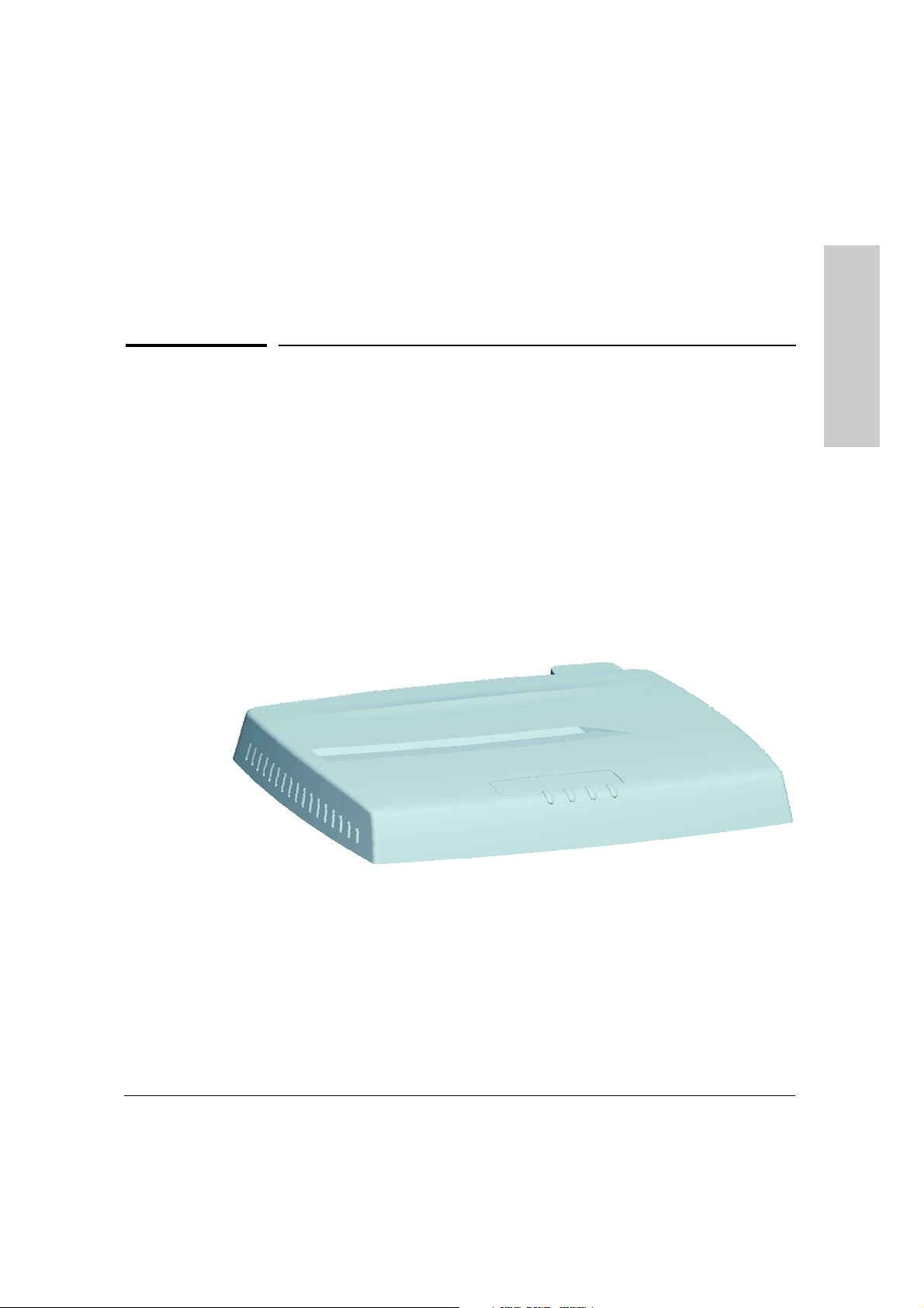
Introducing the HP ProCurve
Introducing the HP ProCurve RSVLC-0501
The HP ProCurve RSVLC-0501 is an enterprise-class, dual-radio 802.11b/g and
802.11a/b/g access point that offers maximum flexibility in deployment and
optimum throughput for high-density usage areas.
The access point provides comprehensive security and management features
and is capable of supporting all types of wireless clients in the same coverage
area. The unit includes internal diversity antennas for both radios and also
connectors for attaching a variety of external antenna options. Mounting
options for the unit include horizontal surface, wall, suspended ceiling T-rail,
and plenum space.
HP ProCurve RSVLC-0501 NA (J8986A)
HP ProCurve RSVLC-0501 WW (J8987A)
RSVLC-0501
Throughout this manual, this access point will be abbreviated as the RSVLC-
0501.
The RSVLC-0501 has one 10/100Base-TX RJ-45 port. This port also supports
Power over Ethernet (PoE) based on the IEEE 802.3af standard. The access
point supports wireless connectivity at speeds up to 54 Mbps based on the
IEEE 802.11g and IEEE 802.11a standards.
1-1
Page 8

Introducing the HP ProCurve RSVLC-0501
This access point is designed to be used primarily for connecting wireless
clients to an enterprise network. This access point allows wireless clients to
connect directly to each other, or to connect to other computers or network
resources located on the wired network.
This chapter describes your HP RSVLC-0501 including:
RSVLC-0501
■ Top and back of the access point
■ Access point features
Introducing the HP ProCurve
1-2
Page 9

Top of the Access Point
Introducing the HP ProCurve RSVLC-0501
Top of the Access Point
Introducing the HP ProCurve
RSVLC-0501
HP ProCurve RSVLC-0501
Indicator Panel
ProCurve
Access Point
NA
530
J8986A
Power LED
ProCurve
Access Point
NA
530
J8986A
Powe r
Radio 1
11b/g
Power
Radio 1
11b/g
Wireless LEDWireless LEDs
Link/Activity
Radio 2
11a/b/g
Link/Activity
LAN
Radio 2
11a/b/g
LAN
Ethernet LED
Power,
LAN Link, and
Wireless Link
LEDs
1-3
Page 10

Introducing the HP ProCurve RSVLC-0501
Top of the Access Point
LEDs
Table 1-1. Access Point LEDs
Access Point
LEDs
RSVLC-0501
Power On (green) The access point is receiving power.
Introducing the HP ProCurve
LAN
(green)
Radio 1 (11b/g)
Radio 2 (11a/b/g)
(green)
State Meaning
Off The access point is NOT receiving power.
Blinking*
(green)
On (amber) A system component of the access point has failed.
Blinking*
(amber)
Off The RJ-45 port has no active network cable connected, or is not receiving a signal.
Blinking or OnThe RJ-45 port has a link indication from a 10 Mbps or 100 Mbps device and is
Off The wireless interface is disabled, either through the access point console or the
Blinking or OnThe wireless interface is enabled and transmitting or receiving traffic. The LED
The access point is undergoing self test or downloading software.
The self test and initialization are in progress after you have power cycled or reset
the access point. The access point is not operational until this LED stops blinking.
A hardware component of the access point has failed.
Otherwise, the port may have been disabled through the access point console, or
the Web browser interface.
transmitting or receiving traffic. The LED blinking rate is proportional to the traffic
rate. If there is no traffic, the blinking rate will be once every five seconds. As the
traffic rate i ncreases, the blinking ra te also increases until th e LED is solid on, which
indicates there no available bandwidth on the port.
Web browser interface.
blinking rate is proportional to the traffic rate. If there is no traffic, the blinking rate
will be once every five seconds. As the traffic rate increases, the blinking rate also
increases until the LED is solid on, which indicates there no available bandwidth
on the interface.
* The blinking behavior is an on/off cycle once every 1.6 seconds, approximately.
1-4
Page 11

Introducing the HP ProCurve RSVLC-0501
Back of the Access Point
Back of the Access Point
Introducing the HP ProCurve
RSVLC-0501
HP ProCurve RSVLC-0501
Lock
48V 0.38A
DC power connector
Auxiliary port and LED
Primary Primary
21
10/100-TX
In
Console
Network port
10/100Base-TX RJ-45
port and PoE input
Console port
Auxiliary Port
Reset Clear
Reset and Clear
buttons
2.4 GHz or 5 GHz Antenna
(802.11a/b/g)
External Ante nna
connectors
2.4 GHz Antenna only
(802.11b/g)
Back Panel Covers
The access point’s ports and connectors on the back of the unit are protected
by two removable plastic covers. One covers the Console port, Clear and Reset
buttons, RJ-45 port, and DC power connector, while allowing twisted-pair and
power cables to pass through. The other cover protects the external antenna
connectors when they are not in use.
Antennas
The access point includes internal diversity antennas for wireless communications. A diversity antenna system uses two identical antennas to receive and
transmit signals, helping to avoid multipath fading effects. When receiving,
the access point checks both antennas and selects the one with the strongest
signal. When transmitting, it will continue to use the antenna previously
selected for receiving. The access point never transmits from both antennas
at the same time.
1-5
Page 12

Introducing the HP ProCurve RSVLC-0501
Back of the Access Point
The access point also supports connectors for various external antenna
options that offer extended radio range and specific radio coverge patterns.
For further information, see chapter 4, “Using an External Antenna with the
RSVLC-0501”.
Lock
RSVLC-0501
Introducing the HP ProCurve
The access point includes a Kensington security slot on the side panel, marked
with the lock symbol ( ). You can prevent unauthorized removal of the
access point by wrapping the Kensington security cable (not provided) around
an unmovable object, inserting the lock into the slot, and turning the key.
Console Port
This port connects a console to the access point using a serial cable. This
connection is described under “Connect a Console to the Access Point” in
chapter 2, “Installing the RSVLC-0501”. The console can be a PC or workstation running a VT-100 terminal emulator, or a VT-100 terminal.
Network Port
The access point includes one 10/100Base-TX port. This port uses the “HP Auto
MDIX” feature, which means that you can use either straight-through or
crossover twisted-pair cables to connect the access point to a switch or
workstation.
Refer to the following section for information on supplying power to the
access point through its RJ-45 port from a network device, such as a switch,
that provides Power over Ethernet (PoE).
Power Connector
The RSVLC-0501 does not have a power switch; it is powered on when
connected to the AC power adapter, and the power adapter is connected to
an active AC power source. The access point's power adapter automatically
adjusts to any voltage between 100--240 volts and either 50 or 60 Hz. There are
no voltage range settings required.
Caution Use only the AC power adapter supplied with the access point. Use of other
adapters, including adapters that came with other HP network products, may
result in damage to the equipment.
1-6
Page 13

Introducing the HP ProCurve RSVLC-0501
Back of the Access Point
The access point may also receive Power over Ethernet (PoE) from a switch
or other network device that supplies power over the network cable based on
the IEEE 802.3af standard.
Note that if the access point is connected to a PoE source device and also
connected to a local power source through the AC power adapter, PoE will
be disabled.
Reset Button
This button is used to reset the hardware or restore the factory defaults:
■ To Reset the Access Point While it is Powered On – When the Reset
button is pressed for about one second all the LEDs turn off, then after
another second the LEDs start to blink rapidly. Releasing the button when
the LEDs are blining rapidly clears any temporary error conditions that
may have occurred and executes the access point self test.
■ To Restore Custom Default Configuration – When pressed with the
Clear button in a specific pattern, any configuration changes you may have
made through the access point console or the Web browser interface are
removed, and the customer-specified default configuration is restored to
the access point. For the specific method to restore the customer default
configuration, see “Restoring Custom and Factory Default Configurations” in chapter 5, “Troubleshooting” of this guide.
■ To Restore Factory Default Configuration – When pressed with the
Clear button in a specific pattern, any configuration changes you may have
made through the access point console or the web browser interface are
removed, and the factory default configuration is restored to the access
point. For the specific method to restore the factory default configuration,
see “Restoring Custom and Factory Default Configurations” in chapter 5,
“Troubleshooting” of this guide.
Introducing the HP ProCurve
RSVLC-0501
Note The system, password, custom default, and factory default reset functions can
be disabled by the access point’s software. For more information, see the
Management and Configuration Guide, which is on the Documentation
CD-ROM that came with your access point.
1-7
Page 14

Introducing the HP ProCurve RSVLC-0501
Back of the Access Point
Clear Button
This button is used for these purposes:
■ Deleting Passwords - When pressed by itself for at least one second, the
button deletes any access point console access passwords that you may
have configured. Use this feature if you have misplaced the password and
RSVLC-0501
Introducing the HP ProCurve
need console access.
■ To Restore Custom Default Configuration – When pressed with the
Reset button in a specific pattern, any configuration changes you may
have made through the access point console or the Web browser interface
are removed, and the customer-specified default configuration is restored
to the access point. For the specific method to restore the customer
default configuration, see “Restoring Custom and Factory Default Configurations” in chapter 5, “Troubleshooting” of this guide.
■ Restoring Factory Default Configuration - When pressed with the
Reset button in a specific pattern, any configuration changes you may
have made through the console, the Web browser interface, and SNMP
management are removed, and the factory default configuration is
restored to the access point. For the specific method to restore the factory
default configuration, see “Restoring Custom and Factory Default Configurations” in chapter 5, “Troubleshooting” of this guide.
1-8
Auxiliary Port
The Auxiliary port is reserved for future use.
Page 15

Introducing the HP ProCurve RSVLC-0501
Access Point Features
Access Point Features
The wireless features of the RSVLC-0501 include:
■ dual-radio design with IEEE 802.11b/g and IEEE 802.11a/b/g radios
■ supports up to 16 Service Set IDentifier (SSID) interfaces per radio
interface
■ security and VLAN settings per SSID interface
■ supports up to 256 wireless clients per radio interface
■ IEEE 802.11a/b/g Compliant – interoperable with multiple vendors
■ precise control over signal transmission power and data rate
■ advanced security through 64/128/152-bit WEP encryption, Wi-Fi
Protected Access (WPA and WPA2), IEEE 802.1X, remote authentication
via a RADIUS server, and MAC address filtering features to protect your
sensitive data and authenticate only authorized users to your network
■ remote logging of system messages
■ time synchronization via SNTP server for message logs
■ wireless bridging between access points
■ neighbor access point detection
■ Quality of Service (QoS) support through Wi-Fi Multimedia (WMM) and
Spectralink Voice Priority
■ auto channel selection – simplifies deployment by testing all available
channels and selecting the best channel based on signal-to-noise ratio
■ international country configuration – select the appropriate country and
the access point automatically configures radio operation to match regulatory requirements (model J8987A only)
Introducing the HP ProCurve
RSVLC-0501
The other basic features of the RSVLC-0501 include:
■ one 10/100Base-TX RJ-45 port
■ supports Power over Ethernet based on the IEEE 802.3af standard
■ full-duplex operation for the 10/100 RJ-45 port
■ easy management of the access point through several available interfaces:
• console interface—a full featured, easy to use, VT-100 terminal
interface that is especially good for out-of-band access point management and for Telnet or Secure Shell access to the access point
• Web browser interface—an easy to use built-in graphical interface
that can be accessed from common Web browsers (includes support
for secure HTTP connections)
1-9
Page 16

Introducing the HP ProCurve RSVLC-0501
Access Point Features
• SNMP—a network management application such as HP ProCurve
Manager can manage the access point via the Simple Network
Management Protocol (SNMP) from a network management station
(supports SNMP versions 1, 2c, and 3)
■ support for group-based access point configuration
■ support for IEEE 802.1Q-compliant VLANs (as specified for each client in
RSVLC-0501
the RADIUS server) so that wireless clients can join the appropriate
logical grouping for the network user’s needs
Introducing the HP ProCurve
■ RADIUS Accounting for logging user activity on the network
■ support for many advanced features to enhance network performance—
for a description, see the Management and Configuration Guide, which
is on the Documentation CD-ROM that is included with your access point.
■ download of new access point software for product enhancements or
software updates
■ upload and download of access point configuration files
1-10
Page 17

Installing the RSVLC-0501
The HP RSVLC-0501 is easy to install. It comes with an accessory kit that
includes a bracket for mounting the access point on a wall or to a suspended
ceiling T-rail. The bracket is designed to allow mounting the access point in a
variety of locations and orientations.
This chapter shows you how to install your RSVLC-0501.
Included Parts
The RSVLC-0501 has the following components shipped with it:
■ HP ProCurve RSVLC-0501 Installation and Getting Started Guide
(J8986A-90001), this manual
■ HP ProCurve Product Documentation CD-ROM
(contains PDF file copies of the documentation for the RSVLC-0501,
including the Management and Configuration Guide)
■ Customer Support/Warranty booklet
■ Accessory kit (5069-5700)
• four 5/8-inch number 12 wood screws to attach the access point to a
wall
• four plastic wall plugs for mounting on a brick or concrete wall
• four rubber feet
■ Mounting bracket (5092-0711)
■ AC power adapter (5092-0728)
■ AC power cord, one of the following:
2
Installing the RSVLC-0501
United States/Canada/Mexico
Continental Europe
United Kingdom/Hong Kong/Singapore
Australia/New Zealand
Japan
China
Denmark
Switzerland
8120-0740
8121-0731
8121-0739
8121-0730
8121-0736
8121-0742
8121-0733
8121-0738
2-1
Page 18

Installing the RSVLC-0501
Installation Procedures
Installation Procedures
Summary
Follow these easy steps to install your access point. The rest of this chapter
provides details on these steps.
1. Prepare the installation site (page 2-4). Make sure that the physical
environment into which you will be installing the access point is properly
prepared, including having the correct network cabling ready to connect
to the access point and having an appropriate location for the access
point. Please see page 2-2 for some installation precautions.
2. Verify that the access point passes self test (page 2-5). This is a
simple process of plugging the access point into a power source, or
connecting it to a switch that provides Power over Ethernet, and
observing that the LEDs on the access point’s top panel indicate correct
access point operation.
Installing the RSVLC-0501
3. Mount the access point (page 2-7). The RSVLC-0501 can be mounted
on a wall, on a suspended ceiling T-rail, or on a horizontal surface.
4. Connect power to the access point (page 2-11). Once the access
point is mounted, plug it into a nearby main power source, or connect it
to a switch that provides Power over Ethernet.
5. Connect to the network (page 2-12). Using the appropriate network
cable, connect the access point to a network connection point, such as a
switch. The network connection can also be used to provide power to the
access point through its PoE feature.
6. Connect a console to the access point (optional—page 2-13). You
may wish to modify the access point’s configuration, for example, to
configure an IP address so it can be managed using a web browser or
through a Telnet session. Configuration changes can be made easily by
using a console cable to connect a PC to the access point’s console port.
At this point, your access point is fully installed. See the rest of this chapter if
you need more detailed information on any of these installation steps.
2-2
Page 19

Installing the RSVLC-0501
Installation Procedures
Installation Precautions:
Follow these precautions when installing your HP RSVLC-0501:
Cautions ■ Make sure that the power source circuits are properly grounded, then use
the power adapter supplied with the access point to connect it to the
power source.
■ You can alternatively power the access point through a network connec-
tion to a switch or other network connection device that provides Power
over Ethernet. However, note that if the access point is connected to a
power source using its AC power adapter, Power over Ethernet is
disabled.
■ Use only the AC power adapter supplied with the access point. Use of
other adapters, including adapters that came with other HP network
products, may result in damage to the equipment.
■ When using the acess point's AC power adapter, note that the AC outlet
should be near the access point and should be easily accessible in case
the access point must be powered off.
■ Ensure that the access point does not overload the power circuits, wiring,
and over-current protection. To determine the possibility of overloading
the supply circuits, add together the ampere ratings of all devices installed
on the same circuit as the access point and compare the total with the
rating limit for the circuit. The maximum ampere ratings are usually
printed on devices near the AC power connectors.
■ Do not install the access point in an environment where the operating
ambient temperature might exceed 50° C (122° F).
■ Make sure the air flow around the sides of the access point is not
restricted.
Installing the RSVLC-0501
2-3
Page 20

Installing the RSVLC-0501
Installation Procedures
1. Prepare the Installation Site
■ Cabling Infrastructure - Ensure that the cabling infrastructure meets
the necessary network specifications. See the following table for cable
types and lengths, and see appendix B, “Access Point Port and Network
Cables” for more information.
Table 2-1. Summary of Cable Types to Use With the Access Point
Port Type Cable Type Length Limits
Twisted-Pair Cables
Installing the RSVLC-0501
10/100Base-TX • 10 Mbps operation:
Category 3, 4, or 5, 100-ohm unshielded
twisted-pair (UTP)
• 100 Mbps operation:
Category 5, 100-ohm UTP or shielded
twisted-pair (STP) cable.
■ Installation Location - Before installing the access point, plan its loca-
tion and orientation relative to other devices and equipment:
• Try to place the access point in the center of your wireless network.
Normally, the higher you place the antennas, the better the performance. You may need to reposition the access point after testing the
signal strength on several wireless clients to ensure that the access
point’s location provides optimal reception throughout the service
area.
• At the back of the access point, leave at least 7.6 cm (3 inches) of
space for the twisted-pair cabling and the power cord.
• On the sides of the access point, leave at least 7.6 cm (3 inches) for
cooling.
100 meters
Note: Since the 1 0Base-T operation is through
the 10/100Base-TX port on the access point, if
you ever want to upgrade the ports on other
devices to 100Base-TX, it would be best to
cable the 10/100Base-TX port on the access
point initially with category 5 cable.
The 10/100-Base-TX port on the RSVLC-0501
uses the “HP Auto MDIX” feature, which
means that you can use either straightthrough or crossover twisted-pair cables to
connect the access point to a switch or
workstation.
2-4
Page 21

Installing the RSVLC-0501
Installation Procedures
2. Verify the Access Point Passes the Self Test
Before mounting the access point in its network location, you should first
verify that it is working properly by plugging it into a power source, or
connecting it to a switch that provides Power over Ethernet, and verifying that
it passes its self test.
1. Connect a network cable from a PoE source device (such as a switch) to
the RJ-45 port on the back of the access point, or connect the supplied
power adapter to the power connector on the back of the access point,
and then into a properly grounded electrical outlet.
Primary Primary
21
Installing the RSVLC-0501
48V 0.38A
Or connect power adap ter
to the power connector
10/100-TX
In
Connect network
cable to PoE switch
Console
Auxiliary Port
Reset Clear
2.4 GHz or 5 GHz Antenna
(802.11a/b/g)
2.4 GHz Antenna only
(802.11b/g)
Note The RSVLC-0501 does not have a power switch. It is powered on when the
power adapter is connected to the access point and to a power source, or when
a network cable is connected to the access point and to a network device that
provides Power over Ethernet. For safety, when connecting to an electrical
outlet, the power outlet should be located near the access point.
Use only the AC power adapter supplied with the access point. Use of other
adapters, including adapters that came with other HP network products, may
result in damage to the equipment.
2-5
Page 22

Installing the RSVLC-0501
Installation Procedures
2. Check the LEDs on the access point as described below.
Installing the RSVLC-0501
ProCurve
Access Point
NA
530
J8986A
Power LED
Power
Radio 1
Link/Activity
11b/g
Wireless LEDs Ethernet LED
Radio 2
11a/b/g
LAN
When the access point is powered on, it performs its diagnostic self test.
The self test takes approximately 50 seconds to complete.
LED Behavior:
During the self test:
• The Power, LAN, Radio 1, and Radio 2 LEDs turn on and off several
times during phases of the self test.
When the self test completes successfully:
•The Power LED remains on green.
•The LAN and Radio LEDs on the top of the access point go into their
normal operational mode:
– If the ports are connected to active network devices, the LEDs
should be blinking.
– If the ports are not connected to active network devices, the LEDs
stay off.
2-6
If the LED display is different than what is described above, especially if
the Power LED does not stop blinking or turns on amber, the self test has
not completed correctly. Refer to chapter 5, “Troubleshooting” for diagnostic help.
Page 23

Installing the RSVLC-0501
Installation Procedures
3. Mount the Access Point
After you have verified that the access point passes the self test, you are ready
to mount the access point in a stable location. The RSVLC-0501 can be
mounted in these ways:
■ on a wall
■ on a suspended ceiling T-rail
■ on a horizontal surface
Wall Mounting
You can mount the access point on a wall as shown in the illustrations on the
next page.
Caution The access point should be mounted only to a wall or wood surface that is at
least 1/2-inch plywood or its equivalent.
1. Position the mounting bracket on the wall, and mark the holes. The
orientation shown in the following figure is the most secure position for
mounting the access point. Do not mount the access point with its ports
and connectors pointing down.
Installing the RSVLC-0501
2. To mount the access point on a plastered brick or concrete wall, first drill
four holes 22 mm deep and 3.5 mm in diameter, and press the four included
wall plugs firmly into the drilled holes until they are flush with the surface
of the wall.
3. Position the mounting bracket over the drilled holes, then insert the four
5/8-inch number 12 wood screws in the holes and tighten down the screws.
4. There are four recess slots on the bottom of the access point that match
up with four protrusions on the mounting bracket, as shown in the
following figures.
Slide the access point down onto the bracket so that the four protrusions
on the bracket enter the four recess slots on the bottom of the access
point. Push the access point firmly down onto the bracket until clicks into
a locked position.
5. To prevent unauthorized removal of the access point, you can use a
Kensington Slim MicroSaver security cable (not included) to attach the
access point to an immovable object.
2-7
Page 24

Installing the RSVLC-0501
Installing the RSVLC-0501
Installation Procedures
Mounting the Bracket on a Wall
5/8-inch
wood screws
2-8
Page 25

Mounting
slots
Installing the RSVLC-0501
Installation Procedures
Sliding the Access Point onto the Bracket
Mounting
points
Installing the RSVLC-0501
Suspended Ceiling Mounting
You can mount the access point on a suspended ceiling T-rail as shown in the
illustrations on the next page.
1. Attach the access point to its mounting bracket by sliding the unit down
onto the bracket so that the four protrusions on the bracket enter the four
recess slots on the bottom of the access point. Push the access point firmly
down onto the bracket until clicks into a locked position.
2. Position the access point with its mounting bracket at a slight angle to the
suspended ceiling T-rail.
3. Push the access point firmly onto the T-rail, then turn anticlockwise until
the rail snaps into the clips on the access point’s backet.
2-9
 Loading...