

Page 1
Installing the RSVLC-0501
Installing the RSVLC-0501
Installation Procedures
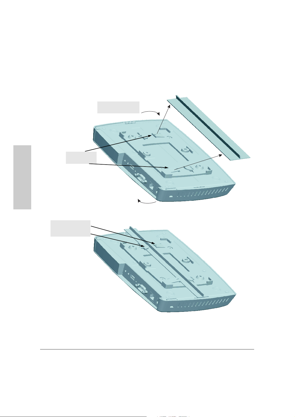
Mounting the Access Point on a Suspended Ceiling T-Rail
2. Turn access point until
clips secure T-rail
1. Push T-rail onto
bracket clips
One side of T-rail held
under tab, the other
side help by clip
2-10
Page 2

Installing the RSVLC-0501
Installation Procedures
Horizontal Surface Mounting
Place the access point on a table or other horizontal surface. The access point
accessory kit provides rubber feet that can be used to help keep the access
point from sliding on the surface.
Attach the rubber feet to the four corners on the bottom of the access point
within the embossed circles. Use a sturdy surface in an uncluttered area. You
may want to secure the networking cable and access point’s power cord to
the table leg or other part of the surface structure to help prevent tripping over
the cords.
Caution Make sure the air flow is not restricted around the sides of the access point.
4. Connect the Access Point to a Power Source
1. Plug the included power adapter into the access point’s power connector
and into a nearby AC power source.
Or, alternatively, connect the Ethernet port on the access point to a switch
or other network device that provides Power over Ethernet.
2. Re-check the LEDs during self test. See “LED Behavior” on page 2-6.
Installing the RSVLC-0501
2-11
Page 3
Installing the RSVLC-0501
Installing the RSVLC-0501
Installation Procedures
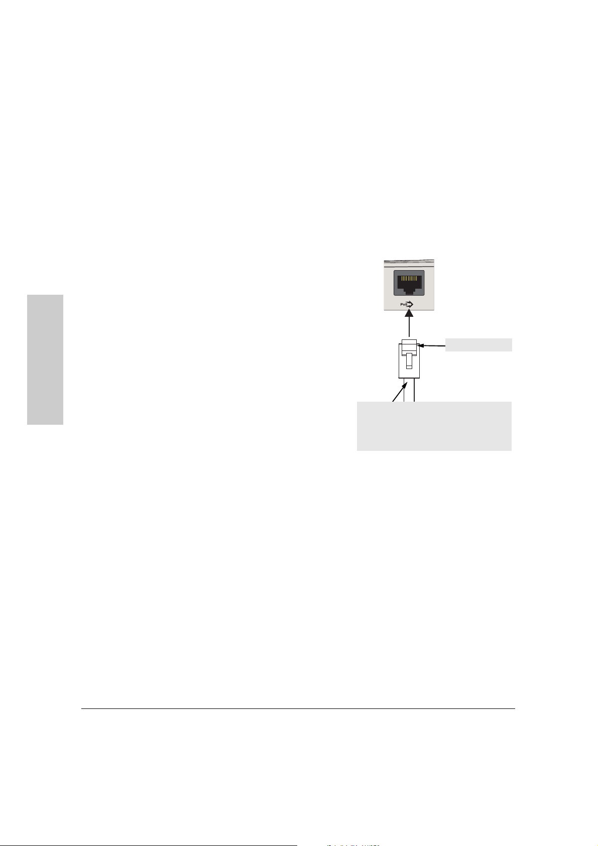
5. Connect the Network Cable
Connect the network cable, described under “Cabling Infrastructure”
(page 2-4), from the network device or your patch panel to the RJ-45 port on
the access point.
Using the RJ-45 Connectors
To c o nne c t:
Push the RJ-45 plug into the RJ-45
port until the tab on the plug clicks
into place. When power is on for the
access point and for the connected
device, the 10/100Base-TX link LED
should light to confirm a powered-on
device (for example, a switch) is at
the other end of the cable.
If the 10/100Base-TX link LED does
not go on when the network cable is
connected to the port, see “Diagnosing with the LEDs” in chapter 5,
“Troubleshooting”.
To disconnect:
Cable:
• Category 3, 4, or 5 for 10 Mbps ports (UTP)
• Category 5 or better for 100 Mbps ports (STP)
Maximum distance: 100 meters
Press the small tab on the plug and pull the plug out of the port.
10/100-TX
8A
In
RJ-45 connector
2-12
6. (Optional) Connect External Antennas to the Access
Point
If you intend to use optional external antennas with the access point, connect
them by following the instructions in chapter 4, “Using an External Antenna
with the RSVLC-0501”.
Page 4

Installing the RSVLC-0501
Installation Procedures
7. (Optional) Connect a Console to the RSVLC-0501
The RSVLC-0501 has a full-featured, easy to use console interface for
performing access point management tasks, including the following:
■ modify the access point’s configuration to optimize access point perfor-
mance, enhance network traffic control, and improve network security
■ download new software to the access point
■ set a Manager password to control access to the access point from the
console, Web browser interface, and network management stations
The console can be accessed through these methods:
■ Out-of-Band: Use a serial cable for connecting a PC or VT-100 terminal
to be used as a console directly to the access point.
■ In-Band: Access the console using Telnet or Secure Shell (SSH) from a
PC on the network, and a VT-100 terminal emulator. This method requires
that you first configure the access point with an IP address and subnet
mask by using either out-of-band console access or through DHCP. For
more information on IP addressing and on starting a Telnet or SSH session,
see chapter 3, “Getting Started With Access Point Configuration”, and the
Management and Configuration Guide, which is on the Documentation
CD-ROM that came with your access point.
Installing the RSVLC-0501
The RSVLC-0501 can simultaneously support one out-of-band console session
through the Console Port and four in-band Telnet or SSH console sessions.
Note For information on using the Web browser interface to configure the access
point, refer to the Management and Configuration Guide.
Terminal Configuration
To connect a console to the access point, configure the PC terminal emulator
as a DEC VT-100 (ANSI) terminal or use a VT-100 terminal, and configure either
one to operate with these settings:
• 9600 baud
• 8 data bits, 1 stop bit, no parity, and flow control set to None
• For the Windows Terminal program, also disable (uncheck) the “Use
Function, Arrow, and Ctrl Keys for Windows” option
• For the Hilgraeve HyperTerminal program, select the “Terminal keys”
option for the “Function, arrow, and ctrl keys act as” parameter
You can only attach to the console using these configuration settings.
2-13
Page 5
Installing the RSVLC-0501
R
8
Installation Procedures
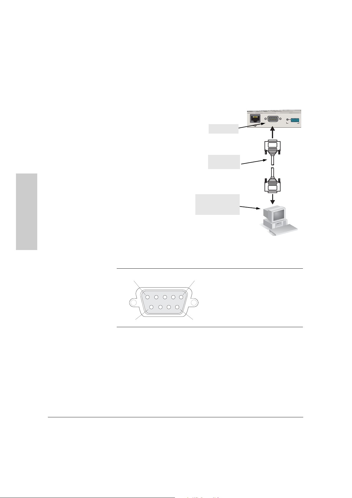
Direct Console Access
To connect a console to the
access point, follow these steps:
1. Connect the PC or terminal
to the access point’s Console
port using a DB-9 female-tofemale serial cable. (If your
PC or terminal has a 25-pin
serial connector, first attach
a 9-pin to 25-pin straightthrough adapter at one end
of the console cable.)
Console port
Console cable
(not supplied)
10/100-TX
A
Console
In
Auxiliary Port
Installing the RSVLC-0501
The Console cable is
described below. A nullmodem cable or an HP
PC running a terminal
emulator program, or
a VT-100 terminal
serial cable, part number
5184-1894 (shipped with
many HP ProCurve
switches), may be used.
RSVLC-0501 serial port pin and signalling details
RSVLC-0501 Pin Assignment Pin Number Access Point Signal (DTE)
1
DB-9 male
5
1
2
3
4
5
6
7
6
9
8
9
Reserved
RXD (input)
TXD (output)
Reserved
GND
Reserved
RTS (output)
CTS (input)
Reserved
Connection to PC serial ports also requires a crossover (null-modem)
cable with a female DB-9 connector on both ends. Terminal connections
will vary, requiring either a DB-9 or DB-25 connector, male or female.
Serial cable options between an HP ProCure RSVLC-0501 and a PC
terminal are shown in the following table.
2-14
Page 6
Installing the RSVLC-0501
Installation Procedures
Note: As indicated in the following table, some of the wires should not
be connected. If you do connect the wires that are labeled “Reserved”,
you might get unexpected results with some terminals.
Serial interface signal directions
DB-9 (DTE)
RSVLC-0501
1
2
3
4
5
6
7
8
9
Reserved
Reserved
GND
Reserved
Reserved
DB9 (DTE)
Terminal or PC
1
2
3
4
5
6
7
8
9
DB-9 (DTE)
RSVLC-0501
1
2
3
4
5
6
7
8
9
Reserved
Reserved
GND
Reserved
Reserved
DB-25 (DTE)
Terminal or PC
8
3
2
20
7
6
4
5
22
2. Turn on the terminal or PC’s power and, if using a PC, start the PC terminal
program.
3. Enter admin at the Username: prompt, and press the
[Enter] key at the
Password prompt. You will then see the access point console command
(CLI) prompt, for example:
HP ProCurve RSVLC-0501#
If you want to continue with console management of the access point at this
time, see chapter 3, “Getting Started With Access Point Configuration” for
some basic configuration steps. For more detailed information, refer to the
Management and Configuration Guide, which is on the Documentation
CD-ROM that came with your access point.
Installing the RSVLC-0501
2-15
Page 7
Installing the RSVLC-0501
Sample Network Topologies
Sample Network Topologies
This section shows you a few sample network topologies in which the RSVLC0501 is implemented. The wireless solution supports a stand-alone wireless
network configuration as well as an integrated configuration with wired
Ethernet LANs. Wireless network cards, adapters, and access points can be
configured as:
■ ad hoc for departmental or SOHO LANs
■ infrastructure for wireless LANs
■ infrastructure wireless LAN for roaming wireless PCs
For more topology information, see the HP network products World Wide Web
site, http://www.hp.com/go/hpprocurve.
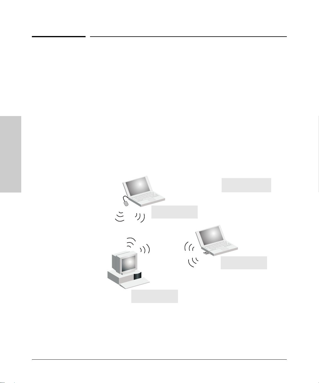
Ad Hoc Wireless LAN (no access point)
Installing the RSVLC-0501
Ad Hoc Network with
No Access Point
Notebook with
Wireless USB Adapter
Notebook with
Wireless PC Card
PC with
Wireless PCI Adapter
An ad-hoc wireless LAN consists of a group of computers, each equipped with
a wireless adapter, connected via radio signals as an independent wireless
LAN. Computers in a specific ad-hoc wireless LAN must therefore be configured to the same radio channel. An ad-hoc wireless LAN can be used for a
branch office or SOHO operation.
2-16
Page 8
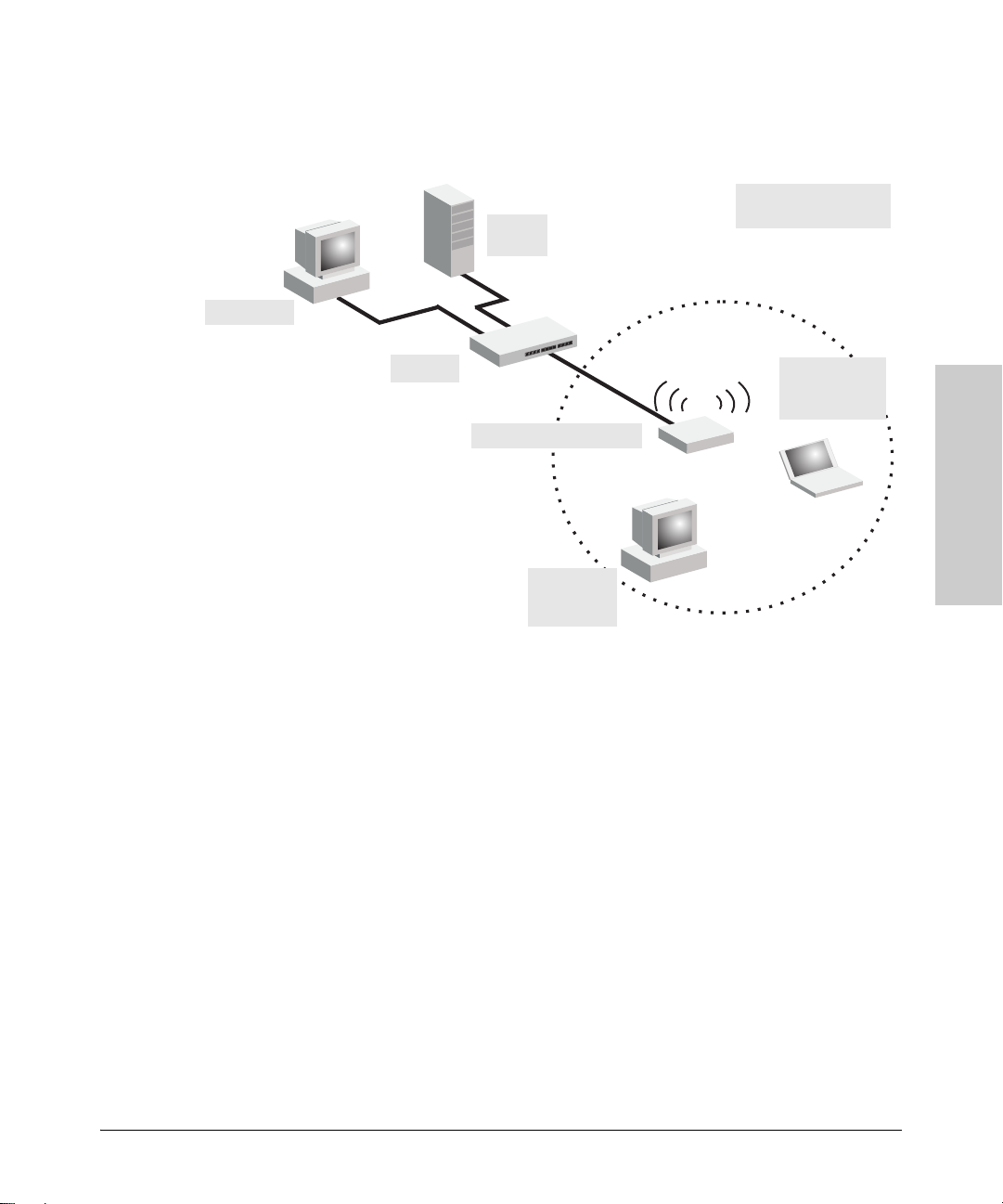
Desktop PC
Infrastructure Wireless LAN
File
Server
Installing the RSVLC-0501
Sample Network Topologies
Wired LAN Extension
to Wireless Adapters
Switch
Notebook with
wireless PC
Card Adapter
RSVLC-0501
PC with
wireless PCI
Adapter
The RSVLC-0501 is designed to provide access to a wired LAN for wireless
clients. An integrated wired/wireless LAN is called an Infrastructure configuration. A Basic Service Set (BSS) consists of a group of wireless PC users, and
an access point that is directly connected to the wired LAN. Each wireless PC
in this BSS can talk to any computer in its wireless group, or access other
computers or network resources in the wired LAN infrastructure via the
access point.
The infrastructure configuration not only extends the accessibility of wireless
PCs to the wired LAN, but also increases the effective wireless transmission
range for wireless PCs by passing their signal through one or more access
points.
Installing the RSVLC-0501
2-17
Page 9
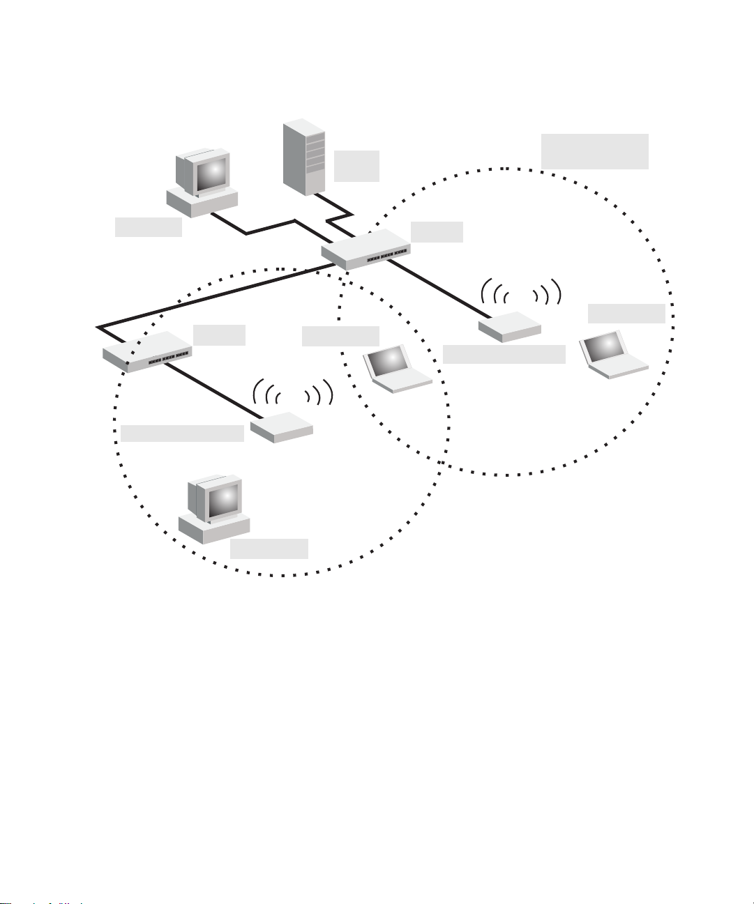
Infrastructure Wireless LAN for Roaming Wireless PCs
Seamless Roaming
File
Server
for Wireless Clients
Desktop PC
RSVLC-0501
Switch
Wireless Client
Switch
Wireless Client
RSVLC-0501
<BSS2>
<ESS>
<BSS1>
Wireless Client
The Basic Service Set (BSS) defines the communications domain for each
access point and its associated wireless clients. The BSS ID is a 48-bit binary
number based on the access point’s wireless MAC address, and is set automatically and transparently as clients associate with the access point. The BSS ID
is used in frames sent between the access point and its clients to identify traffic
in the service area.
The BSS ID is only set by the access point, never by its clients. The clients
only need to set the Service Set Identifier (SSID) that identifies the service set
provided by one or more access points. The SSID can be manually configured
by the clients, can be detected in an access point’s beacon, or can be obtained
by querying for the identity of the nearest access point. For clients that do not
need to roam, set the SSID for the wireless card to that used by the access
point to which you want to connect.
Page 10

Installing the RSVLC-0501
Sample Network Topologies
A wireless infrastructure can also support roaming for mobile workers. More
than one access point can be configured to create an Extended Service Set
(ESS). By placing the access points so that a continuous coverage area is
created, wireless users within this ESS can roam freely. All HP wireless
network cards, adapters, and access points within a specific ESS must be
configured with the same SSID.
Installing the RSVLC-0501
2-19
Page 11

Installing the RSVLC-0501
Installing the RSVLC-0501
Sample Network Topologies
— This page is intentionally unused. —
2-20
Page 12

Getting Started With Access Point
Configuration
This chapter is a guide for using the access point’s console to quickly assign
an Internet Protocol (IP) address and subnet mask to the access point, set a
manager password, and, optionally, configure other basic features.
For more information on using the access point’s console and the Web browser
interface, please see the Management and Configuration Guide, which is on
the Documentation CD-ROM that came with your access point.
Recommended Minimal Configuration
In the factory default configuration, the access point is configured as a DHCP
client. If the access point fails to obtain an IP address from the DHCP server,
it uses its default static IP address of 192.168.1.1. If this address is not
compatible with your network, then the access point can only be managed
through a direct console connection. To manage the access point through inband (networked) access, you should configure the access point with an IP
address and subnet mask compatible with your network. Also, you should
configure a Manager password to control access to the console and Web
browser interface. Other parameters can be left at their default settings or you
can configure them with values you enter.
3
Getting Started With Access
Point Configuration
Caution The country code for the HP ProCurve RSVLC-0501 NA (J8986A) sold in the
United States and Canada is preset and cannot be changed. This means that
only radio channels 1-11 are available for this model.
The country code for the HP ProCurve RSVLC-0501 WW (J8987A) sold in other
countries is not set, and must be configured before you can enable radio
communications for the access point. Setting the country code enables only
those radio channels permitted for wireless networks in the specified country.
Please refer to“To Set the Access Point’s Country Code” on page 3-4 for
information on setting the country code.
Note that once you have set the country code, it can only be changed by
restoring the factory default settings as described under “Restoring Custom
and Factory Default Configurations” on page 5-8.
3-1
Page 13

Getting Started With Access Point Configuration
Many other features can be configured through the access point’s console
interface to optimize the access point’s performance, to enhance your control
of the network traffic, and to improve network security. Once an IP address
has been configured on the access point, these features can be accessed more
conveniently through a remote Telnet or Secure Shell (SSH) session, or
through the access point’s Web browser interface.
For more information on IP addressing, refer to “Configuring IP Settings” in
the Management and Configuration Guide.
Note By default, the access point is configured to acquire an IP address configura-
tion from a DHCP server. To use DHCP instead of the manual method
described in this chapter, see “Configuring IP Settings” in the Management
and Configuration Guide, which is on the Documentation CD-ROM that came
with your access point.
Using the Command Line Interface
The quickest and easiest way to minimally configure the access point for
management and password protection in your network is to use a direct
console connection to the access point, start a console session, and access
the command line interface (CLI).
Getting Started With Access
To Set the Manager User Name and Password
Management access to the access point’s Web and CLI interface is controlled
through user names and passwords. A Manager user name and password
allows full read/write privileges for the Web and CLI. An Operator user name
and password can also be configured. The Operator is restricted to read-only
access. A maximum of only two users can be configured, one Manager and
Point Configuration
3-2
one Operator.
1. Using the method described in the preceding chapter, connect a terminal
device to the access point, and press
[Enter] to initiate the console connec-
tion.
2. Type admin for the default Manager user name and also admin for the
default password, then press
[Enter]. The CLI prompt appears displaying
the access point’s model number.
ProCurve-AP-RSVLC-0501 login: admin
Password:
ProCurve RSVLC-0501#
Page 14
Getting Started With Access Point Configuration
3. Type configure to enter global configuration mode.
ProCurve RSVLC-0501#configure
ProCurve RSVLC-0501(config)#
4. Type password manager password to create a password for the Manager,
where password can consist of between 3 and 16 alphanumeric characters
and is case sensitive.
ProCurve RSVLC-0501(config)#password manager 1AB2F
ProCurve RSVLC-0501(config)#
To Set the Access Point’s IP Address
By default, the access point is configured to automatically receive IP
addressing from a Dynamic Host Configuration Protocol (DHCP) server.
However, if you are not using a DHCP server to configure IP addressing, use
the CLI to manually configure the IP values.
1. From the global configuration mode, type interface ethernet to access the
Ethernet interface-configuration mode.
ProCurve RSVLC-0501(config)#interface ethernet
ProCurve RSVLC-0501(ethernet)#
2. Type show ip to display the access point’s default IP configuration,
including IP address, subnet mask, and default gateway. The following
illustration shows the default settings.
ProCurve RSVLC-0501(ethernet)# show ip
IP Address Information:
System Host Name ProCurve-RSVLC-0501
IP Address 192.168.1.1
Subnet Mask 255.255.255.0
Default Gateway not set
DHCP Client Enabled
DNS Information (Obtained from DHCP):
Domain Name Suffix not set
Primary DNS Server not set
Secondary DNS Server not set
ProCurve RSVLC-0501(ethernet)#
3. To manually assign an IP address, type ip address ip-address netmask,
where ip-address is the access point’s IP address and netmask is the
network mask for the network. If managing the access point from another
subnet, you must also set the default gateway with the ip default-gateway
Getting Started With Access
Point Configuration
3-3
Page 15

Getting Started With Access Point Configuration
gateway command, where gateway is the address of the default gateway
router. Check with your system administrator to obtain an IP address that
is compatible with your network.
ProCurve RSVLC-0501(ethernet)#ip address 192.168.2.2 255.255.255.0
ProCurve RSVLC-0501(ethernet)#ip default-gateway 192.168.2.254
ProCurve RSVLC-0501(ethernet)#
To Set the Access Point’s Country Code
If you are using the HP ProCurve RSVLC-0501 NA (J8986A) model sold in the
United States, radio channels 1 - 11 are the only options supported under FCC
regulations, and cannot be changed. However, if you are using HP ProCurve
RSVLC-0501 WW (J8987A) model sold in other countries, then you need to set
the country code to indicate the channels permitted for your area. The country
code can only be set using the CLI.
Select the two-character code for your country (refer to the Management and
Configuration Guide for a full list of codes), then enter the country command
followed by your country code; for example, gb for Great Britain.
ProCurve RSVLC-0501#country gb
ProCurve RSVLC-0501#
Getting Started With Access
To Configure Radio Settings
The access point supports up to 16 Service Set IDentifier (SSID) interfaces
per physical radio interface. Most radio parameters apply globally to all
configured SSID interfaces. For each SSID interface, different security
settings, VLAN assignments, and other parameters can be applied.
One SSID interface on each radio interface is set as the primary. The primary
Point Configuration
Note The radios are disabled if the Country Code is not set. Once the Country Code
3-4
SSID is the only SSID broadcast in the radio’s beacon frames. Other created
SSID interfaces are set as secondary. Secondary SSIDs are all “hidden,” only
being advertised in probe responses.
is set, the radios are automatically enabled.
Page 16
Getting Started With Access Point Configuration
1. From any command level, type the show radio command followed by the
radio number to display the radio’s configuration, including the radio
mode, radio channel, and operation status. The following illustration
shows the default settings.
ProCurve RSVLC-0501# show radio 1
Description Radio 1 - 802.11g
Base MAC 00:14:C2:A5:1D:60 Status Enabled
Mode 802.11g Channel-Policy best
Channel 8 SSIDs Supported 16
TX-Power(%) 100 Local Wls Bridge Fltr Disabled
Antenna Mode diversity Antenna(s) In Use internal
RTS-Threshold 2347 Fragment-Threshold 2346
WMM QoS on Beacon-Interval(K-us) 100
SVP QoS [add-in-future-SSID]
Rate-Limiting (Disabled)
Rate-Limit(packets/second) 50 Burst-Limit(packets/second) 75
802.11h (Enabled) Radar-Detection Enabled
Blocked-Time not set Quiet Duration Interval not set
TX-Mitigation not set Quiet Period (Beacon) not set
AP-Detection (Disabled)
Passive Scan Interval [add-in-future]
ProCurve RSVLC-0501#
2. Type configure to enter global configuration mode, and then type radio 1
to access the wireless interface-configuration mode for radio 1.
ProCurve RSVLC-0501#configure
ProCurve RSVLC-0501(config)#radio 1
ProCurve RSVLC-0501(radio1)#
Getting Started With Access
Point Configuration
3. Set the channel through which the access point’s radio 1 (802.11b/g)
communicates with its wireless clients. The default setting is to statically
set the operating channel number. Type static-channel number, where
number can be from 1 to 14, depending on the wireless regulations specified by your country. Otherwise, type channel-policy best to have the
access point automatically select the best available channel.
ProCurve RSVLC-0501(radio1)#static-channel 11
ProCurve RSVLC-0501(radio1)#
4. To set the primary Service Set Identifier (SSID) for the access point. Type
ssid 1 to enter SSID interface configuration for the primary SSID interface.
Then type ssid identifier, where identifier can consist of up to 32 alphanu-
meric characters and is case sensitive.
ProCurve RSVLC-0501(radio1)# ssid 1
ProCurve RSVLC-0501(radio1-ssid1)# ssid APRSVLC-0501
ProCurve RSVLC-0501(radio1-ssid1)#
3-5
Page 17

Getting Started With Access Point Configuration
5. To configure the access point’s radio 2 interface, type radio 2 and repeat
steps 1 to 4. Note that when the radio 2 interace mode is set to 802.11a,
the available channels are 36 to 165, depending on the country setting.
6. To save all configuration settings from the running configuration file to
the startup configuration file, type write memory from any command level.
ProCurve RSVLC-0501(radio1-ssid1)# write memory
ProCurve RSVLC-0501(radio1-ssid1)#
Here is some information on the basic IP address and wireless configuration
parameters. For more information on these parameters, see the Management
and Configuration Guide, which is on the Documentation CD-ROM that came
with your access point:
Parameter Default
Username admin The name of the manager.
Password admin The password for the manager.
IP Address 192.168.1.1 IP address compatible with your network.
Subnet Mask 255.255.255.0 Subnet mask compatible with your network.
Getting Started With Access
Default Gateway not set IP address of the next-hop gateway node for network traffic that needs to
Radio 1 Mode 802.11g The operating mode for Radio 1.
Radio 2 Mode 802.11a The operating mode for Radio 2.
Primary SSID Radio 1 - SSID 1
Radio 2 - SSID 2
Channel Policy best (auto) The radio channel through which an access point radio communicates
Point Configuration
Wireless Operation Enabled Wireless operation is automatically enabled after you have set the country
Note: The IP address and subnet mask assigned for the access point must be compatible with the IP addressing used
in your network. For more information on IP addressing, see the Management and Configuration Guide, which is on
the Documentation CD-ROM that came with your access point.
be able to reach off-subnet destinations.
The primary Service Set Identifier (SSID) interface for the access point.
Only the primary SSID is broadcast in the access point’s beacon frames.
with its wireless clients. When attempting to connect, most wireless
clients automatically set their radio channel to the same channel used by
the access point.
code.
3-6
Page 18

Getting Started With Access Point Configuration
Where to Go From Here
The above procedure, using the CLI, configured your access point with a
Manager password, IP address, and subnet mask. As a result, with the proper
network connections, you can now manage the access point from a PC
equipped with Telnet or a Secure Shell client, or a Web browser interface. The
above procedure also configured the primary Service Set Identifier (SSID),
the radio channel, and enabled wireless operation. Your wireless clients can
now access the network by setting their SSID and radio channel to the same
values used by the access point. Note that some wireless clients can be
configured to scan all of the radio channels for an access point and the SSID.
Some basic information on managing your access point is included in the next
section. For more information on the console and Web browser interfaces,
and all the features that can be configured on the RSVLC-0501, please see the
Management and Configuration Guide, which is on the Documentation
CD-ROM that came with your access point.
To Recover from a Lost Manager Password: If you cannot start a console session because of a lost manager password, you can clear the password
and user name by getting physical access to the access point and pressing and
holding the Clear button for more than one second.
Caution The Clear button is provided for your convenience, but if you are concerned
with the security of the access point configuration and operation, you can
disable it. For more information, see the Management and Configuration
Guide, which is on the Documentation CD-ROM that came with your access
point.
Getting Started With Access
Point Configuration
3-7
Page 19

Getting Started With Access Point Configuration
Using the IP Address for Remote Access Point Management
Using the IP Address for Remote Access
Point Management
With your RSVLC-0501, you can use the access point’s IP address to manage
the access point from any PC that is on the same subnet as the access point.
You can use either a Telnet or Secure Shell (SSH) session, or a standard Web
browser to manage the access point.
Note To provide more security for the access point, management interfaces that are
not required can be disabled. This includes the Web, Telnet, and SSH, as well
as the serial console port, Clear button, and Reset button. For more information, see the Management and Configuration Guide, which is on the Documentation CD-ROM that came with your access point.
Starting a Telnet Session
To access the access point through a Telnet session, follow these steps:
1. Make sure the access point is configured with an IP address and that the
access point is reachable from the PC that is running the Telnet session
(for example, use a ping command to the access point’s IP address).
Getting Started With Access
2. Start the Telnet program on a PC that is on the same subnet as the access
point and connect to the access point’s IP address.
Example:
telnet 192.168.1.19
Point Configuration
3-8
3. Enter the user name and password. (The default user name is admin and
the default password is also admin. You will then see the access point’s
console command (CLI) prompt, for example:
ProCurve-RSVLC-0501 login: admin
Password:
ProCurve RSVLC-05010#
Enter ? to see a list of commands that can be executed at the prompt.
Entering any command followed by ? displays a list of options that are
available at that point in the command entry.
Page 20

Using the IP Address for Remote Access Point Management
Getting Started With Access Point Configuration
Starting an SSH Session
To access the console through an SSH session, SSH v2.0 client software must
be installed on the management station PC. Note that after boot up, the access
point’s SSH server needs about two minutes to generate host encryption keys.
The SSH server is disabled while the keys are being generated.
Note The access point supports only SSH version 2.0.
To access the access point through an SSH session, follow these steps:
1. Make sure the access point is configured with an IP address and that the
access point is reachable from the PC that is running the SSH session (for
example, use a ping command to the access point’s IP address).
2. Start the SSH client program on a PC that is on the same subnet as the
access point and connect to the access point’s IP address.
Example:
ssh 192.168.1.19
3. Enter the Manager user name and password. (The default Manager user
name is admin and the default password is also admin. You will then see
the access point’s console command (CLI) prompt, for example:
ProCurve-RSVLC-0501 login: admin
Password:
ProCurve RSVLC-0501#
Getting Started With Access
Point Configuration
Starting a Web Browser Session
Your RSVLC-0501 can be managed through a graphical interface that you can
access from any PC or workstation on the same subnet as the access point.
Open a compatible browser and type the access point’s IP address as the URL.
(See “Using the Command Line Interface” on page 3-2 for information on
setting the IP address.) No additional software installation is required to make
this interface available; it is included in the access point’s onboard software.
The operating and Web systems support recommended to manage the access
point through the browser interface are as follows:
■ Microsoft Internet Explorer version 5.5 or 6.x (with up-to-date patch level
for either major version) on Microsoft Windows XP or Microsoft Windows
2000
■ Netscape Mozilla 1.7.x on Redhat Linux version 2.4
■ Mozilla/5.0 (Windows; U; Windows NT 5.1; rv:1.7.3) Gecko/20041001
Firefox/0.10.1
3-9
Page 21
Getting Started With Access Point Configuration
Using the IP Address for Remote Access Point Management
The administration Web browser must have JavaScript enabled to support the
interactive features of the administration interface. It must also support HTTP
uploads to use the firmware upgrade feature.
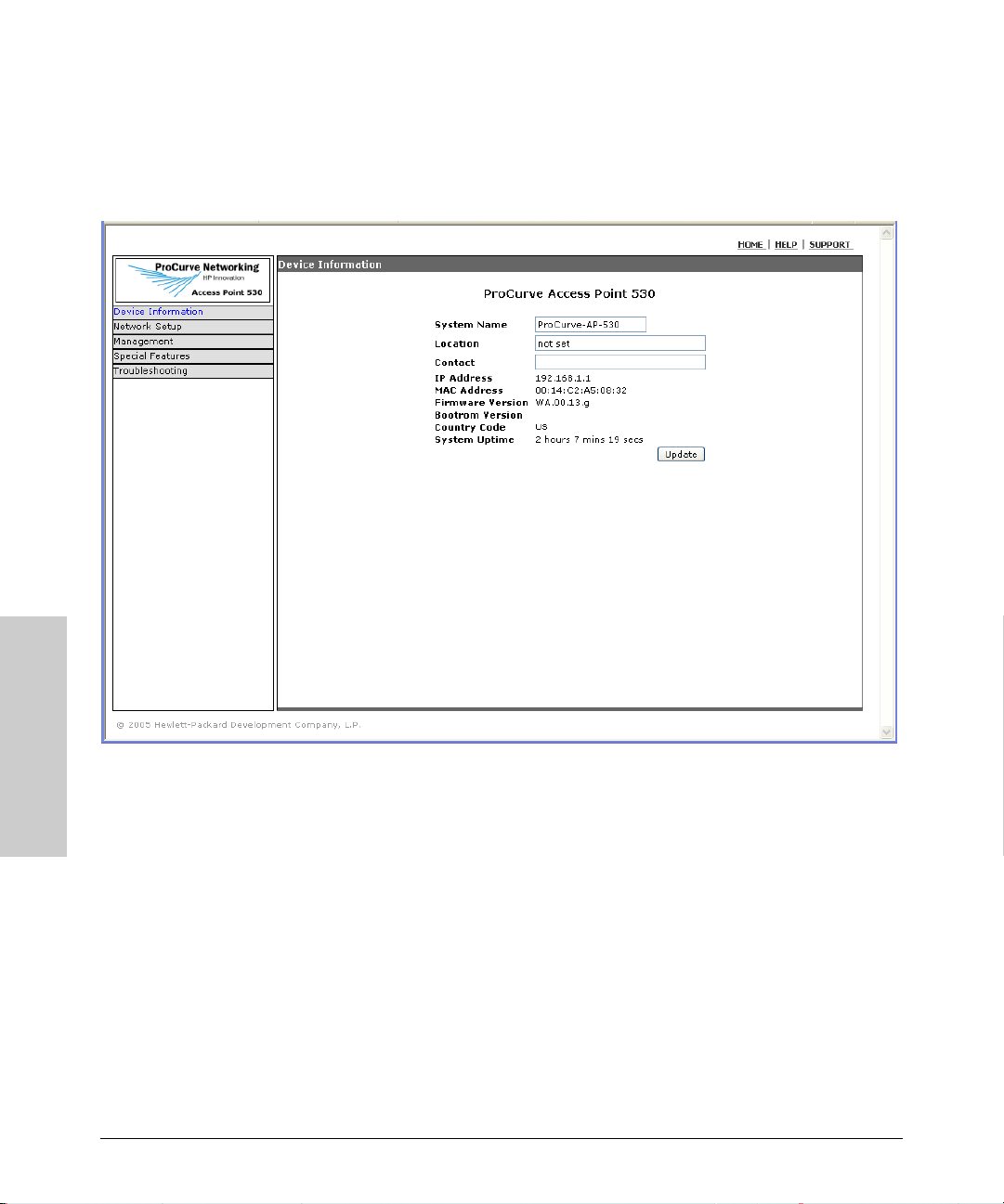
A typical Web browser interface screen is shown in the next illustration.
Getting Started With Access
For more information on using the Web browser interface, please see the
Point Configuration
Management and Configuration Guide, which is on the Documentation
CD-ROM that came with your access point.
A help system is also available for the Web browser interface. Click the HELP
link in the upper-right corner of the screen.
3-10
Page 22

Using an External Antenna with
the RSVLC-0501
The HP RSVLC-0501 provides a variety of external antenna options for
extending the radio range and shaping the coverge area. These antennas offer
a number of different mounting locations, including indoor or outdoor, wall,
ceiling, or radio mast.
This chapter shows you how to install an external antenna for your RSVLC-
0501.
4
Professional
Installation
Required
Only the HP antennas listed in this guide are permitted to be connected to the
RSVLC-0501. You must use the appropriate antennas, cables, and where
applicable, surge arrestors, for your given region. You are responsible for
verifying local regulations or legislation that may impose restrictions on the
use of specific antenna and cable combinations. For this reason, you must
consult with a professional installer who is trained in RF installation and
knowledgeable in the local regulations prior to connecting an external
antenna to your wireless radio product. It is the responsibility of the end user
to ensure that the antenna installation complies with the local radio regulations.
Using an External Antenna
with the RSVLC-0501
4-1
Page 23
Using an External Antenna with the RSVLC-0501
External Antenna Options
External Antenna Options
The RSVLC-0501 external antenna options are outlined in the following table:
Table 4-1. Summary of External Antennas to Use With the RSVLC-0501
Antenna Type Part Number Mounting Horizontal
Beamwidth (3dB)
2.4 GHz 5 dBi indoor/outdoor
omnidirectional
2.4 GHz 8 dBi outdoor
omnidirectional
2.4 GHz 14 dBi indoor/outdoor Yagi J8448A Articulating wall or
2.4 / 5 GHz 3 dBi indoor
omnidirectional diversity
2.4 / 5 GHz 7 dBi indoor/outdoor
directional
5 GHz 6 dBi indoor/outdoor
omnidirectional
5 GHz 14 dBi indoor/outdoor
directional
J8441A Ceiling or mast 360 Degrees 31 Degrees
J8444A Mast 360 Degrees 12 Degrees
34 Degrees 30 Degrees
mast mount
J8997A Ceiling grid 360 Degrees 70 Degrees
J8999A Flush wall mount with
integrated
articulating feature
J8998A Ceiling, mast or
I-beam
J9000A Flush wall mount with
integrated
articulating feature
68 Degrees 66 Degrees
360 Degrees 17 Degrees
29 Degrees 27 Degrees
Ver tical
Beamwidth (3dB)
Using an External Antenna
with the RSVLC-0501
4-2
Page 24

Using an External Antenna with the RSVLC-0501
Installation Procedures
Installation Procedures
Follow these steps to install an external antenna and connect it to the RSVLC-
0501.
Caution Never mount the access point outdoors to be near an external antenna. The
access point must always be installed indoors.
1. Plan the Installation
■ Pigtail Cables - Use the coax pigtail cable attached to the antenna to
connect to the access point. Because most pigtail cables are a relatively
short length (83 cm or 33 inches), be sure to find a suitable mounting
position for the antenna that is not too far from the access point. If an
extension cable is required, please contact a professional installer who is
trained in RF installation and knowledgeable in the local regulations.
■ Installation Location - Plan the antenna’s position and orientation.
Warning The radiated output power of this device is below the FCC radio exposure
limits. Nevertheless, the device should be used in such a manner that the
potential for human contact during normal operation is minimized. To avoid
the possibility of exceeding the FCC radio frequency exposure limits, human
proximity to the antennas should not be less than 25 cm (10 inches) during
normal operation.
Consider these points:
• Use the antenna’s mounting bracket or other hardware, if included.
• For optimum performance, mount antennas as high as possible above
any obstructions, and away from any signal absorbing or reflecting
structures (such as those containing metal)
• Be sure there are no other radio antennas mounted within 2 m (6 ft).
• Consider the antenna’s radio coverage pattern so that it can properly
cover the intended service area.
■ Omnidirectional Antennas - Consider these factors when selecting a
location for these antennas:
• Always mount the antenna in a vertical orientation so that the radio
coverage pattern fills the intended horizontal space.
Using an External Antenna
with the RSVLC-0501
4-3
Page 25

Using an External Antenna with the RSVLC-0501
Installation Procedures
• For optimum coverage, mount the antenna at the center of the area
with a line-of-sight path to all points within the area.
• Avoid mounting next to or near building support columns or other
obstructions that may cause reduced signal or null zones in parts of
the coverage area.
• When mounting outdoors using a mast, make sure that the antenna
extends beyond the top of the mast.
■ Directional Antennas - Consider these factors when selecting a location
for these antennas:
• For optimum coverage, mount the antenna above any obstructions,
directed at the center of the coverage area sector.
• High-gain directional antennas provide a flattened radio coverage
pattern in the horizontal plane. Use the tilting or articulated mounts
to point the antennas towards the coverage area.
■ Outdoor Installation - When installing an antenna outdoors, be sure to
consider these additional factors:
• Always place the antenna away from power and telephone lines
• Make sure that the antenna, any supporting structure, and cables are
all properly grounded.
• For lightning protection, consider using a lightning arrestor immedi-
ately before the cable enters the building.
Using an External Antenna
Warning Never install an antenna or construct a radio mast near overhead power lines.
2. Mount the Antenna
Install the antenna in its planned location using the brackets, clips, or other
hardware included in the antenna package.
Refer to documentation included with the antenna for specific information
and installation instructions.
3. Connect Pigtail Cables to the Access Point
Use the pigtail cables that are attached to the antenna, or are included in the
antenna package. If an extension cable is required, please contact a professional installer who is trained in RF install ation and knowledgeable in the local
regulations.
with the RSVLC-0501
4-4
Page 26

Using an External Antenna with the RSVLC-0501
Installation Procedures
Note that diversity antennas have two pigtail cables. A diversity antenna
includes two internal antenna elements that are identical. Both antenna pigtail
cables must be connected to the access point for correct operation.
Other non-diversity antennas, which have only one pigtail cable, attach to the
access point’s “Primary” antenna connector for the appropriate radio.
To connect pigtail cables to the access point, follow these steps:
1. Disable the access point radio using the web browser interface, CLI, or
SNMP.
2. Remove power to the access point.
3. Remove the connector cover on the back of the access point.
4. For diversity antennas, connect the antenna pigtail cables to the exposed
Reverse SMA connectors for the appropriate radio.
For non-diversity antennas, be sure to connect the single pigtail cable to
the Reverse SMA connector labeled “Primary.”
Screw onto access point’s
Antenna pigtail cable
Reverse SMA connector
y
r
a
m
i
Pr
y
l
n
o
a
n
n
e
t
)
n
g
/
A
b
z
H
y
11
r
.
G
a
2
4
0
.
m
i
8
2
(
Pr
21
a
n
n
e
t
n
A
z
H
)
G
g
/
5
b
r
/
o
a
z
11
H
.
G
2
0
4
.
8
(
2
5. Reconnect power to the access point.
Note Before enabling the radio with an external antenna attached, be sure to first
configure the access point’s antenna mode and type.
Using an External Antenna
with the RSVLC-0501
4-5
Page 27

Using an External Antenna with the RSVLC-0501
Installation Procedures
4. Configure the Antenna Mode and Type
Using the web browser interface, CLI, or SNMP, you must configure the
RSVLC-0501 to use an external antenna. For more information on access point
configuration, see the Management and Configuration Guide, which is on
the Documentation CD-ROM that came with your access point.
The access point must be set for the type of external antenna that is attached,
either a diversity antenna that connects to two access point antenna connectors, or non-diversity antenna that has a single pigtail connection.
Setting the Antenna Mode and Type Using the CLI
1. Type configure to enter global configuration mode.
RSVLC-0501#configure
RSVLC-0501(config)#
2. Type radio 1 to enter interface configuration mode for radio 1.
RSVLC-0501(config)#radio 1
RSVLC-0501(radio1)#
3. Type antenna mode diversity if using a diversity antenna.
Using an External Antenna
RSVLC-0501(radio1)#antenna mode diversity
Typ e antenna mode single if using a non-diversity antenna.
RSVLC-0501(radio1)#antenna mode single
4. Type antenna external to set the access point to use an antenna attached
to the radio’s external antenna connectors.
RSVLC-0501(radio1)#antenna external
Setting the Antenna Mode and Type Using the Web Interface
1. Select Network Setup> Radio tab >[Edit] button > Advanced Settings
Window.
2. To set the radio to use an internal or external antenna, select Internal or
External, using the Antenna Type drop-down.
3. To set the radio to use a specific antenna mode, select Diversity or Single,
using the Antenna Mode drop-down.
4. Click [Update] to set the antenna parameters.
with the RSVLC-0501
4-6
Page 28

Using an External Antenna with the RSVLC-0501
Installation Procedures
Antenna Type selection;
Internal or External.
Antenna Mode selection;
Diversity or Single.
Using an External Antenna
with the RSVLC-0501
4-7
Page 29

— This page is intentionally unused. —
Page 30

5
Troubleshooting
This chapter describes how to troubleshoot your HP ProCurve RSVLC-0501.
Note that this document describes troubleshooting mostly from a hardware
perspective. You can perform more in-depth troubleshooting on the RSVLC0501 using the software tools available with the access point, including the
full-featured console interface and the built-in Web browser interface.
This chapter describes the following:
■ basic troubleshooting tips (page 5-1)
■ diagnosing with the LEDs (page 5-3)
■ proactive networking tools (page 5-5)
■ hardware diagnostic tests (page 5-6)
■ restoring customer and factory default configurations (page 5-8)
■ downloading new software to the RSVLC-0501 (page 5-10)
■ HP Customer Support Services (page 5-10)
Basic Troubleshooting Tips
Troubleshooting
Most problems are caused by the following situations. Check for these items
first when starting your troubleshooting:
■ Connecting to devices that have a fixed full-duplex configuration.
By default, the RJ-45 port uses auto-negotiation to determine the duplex
mode. That is, when connecting to attached devices, the access point will
operate in one of two ways to determine the link speed and the communication mode (half duplex or full duplex):
• If the connected device is also configured to use auto-negotiation, the
access point will automatically negotiate both link speed and communication mode.
• If the connected device has a fixed configuration, for example
100 Mbps, at half or full duplex, the access point will automatically
sense the link speed, but will default to a communication mode of half
duplex.
5-1
Page 31

Troubleshooting
Basic Troubleshooting Tips
Because the RSVLC-0501 behaves in this way (in compliance with the
IEEE 802.3 standard), if a device connected to the access point has a
fixed configuration at full duplex, the device will not connect correctly to
the access point. The result will be high error rates and very inefficient
communications between the access point and the device.
All devices connected to the RSVLC-0501 should be configured to autonegotiate. To correct this problem you have to manually set the access
Troubleshooting
point’s RJ-45 port to match the duplex mode used by the attached device.
■ Faulty or loose cables. Look for loose or obviously faulty connections.
If the cables appear to be OK, make sure the connections are secure. If
that does not correct the problem, try a different cable.
■ Non-standard cables. Non-standard and miswired cables may cause
network collisions and other network problems, and can seriously impair
network performance. Use a new correctly-wired cable or compare your
cable to the cable in appendix B, “Access Point Port and Network Cables”
for pinouts and correct cable wiring. A category 5 cable tester is a
recommended tool for every 100Base-TX network installation.
■ Improper Network Topologies. It is important to make sure you have
a valid network topology. Common topology faults include excessive
cable length and excessive repeater delays between end nodes. If you have
network problems after recent changes to the network, change back to
the previous topology. If you no longer experience the problems, the new
topology is probably at fault. Sample topologies are shown at the end of
chapter 2 in this book, and some topology configuration guidelines can
be found online at the HP ProCurve Web site, http://www.hp.com/rnd/
index.htm. under “network configuration examples.”
■ Mobile users cannot connect to the network. Make sure that the
access point and wireless clients are configured with compatible security
settings. Check to ensure that the wireless client is within the maximum
range supported by the access point. Also verify that the wireless client
has been configured with an IP address compatible with the attached
network, either manually or via DHCP.
5-2
For more information on possible network problems and their solutions, refer
to the technical note “Troubleshooting LAN Performance and Intermittent
Connectivity Problems”, which can be found on the HP ProCurve Web site,
http://www.hp.com/go/hpprocurve, in the Reference Library section under
http://www.hp.com/rnd/library/index.htm under “T” in the “A-Z index.”
Page 32

Diagnosing with the LEDs
Troubleshooting
Diagnosing with the LEDs
Table 5-1 shows LED patterns on the access point that indicate problem
conditions.
1. Check in the table for the LED pattern that you see on your access point.
2. Refer to the corresponding diagnostic tip on the next few pages.
Table 5-1. LED Error Indicators
LED Pattern Indicating Problems
Power Radio LEDs LAN LED
Off with power cord plugged in * * 1
Off without po wer cord plugged in,
but linked to a PoE source
Prolonged Blinking
On Off * 4
On * Off with cable
On * On, but the port is not
†
**2
**3
connected
communicating
Diagnostic
Tips
5
6
Troubleshooting
* This LED is not important for the diagnosis.
†
The blinking behavior is an on/off cycle once every 3 seconds, approximately.
Diagnostic Tips:
Tip Problem Solution
1 The access point
is not plugged
into an active AC
power source, or
the access
point’s AC power
adapter may
have failed.
1. Verify that the power cord is plugged into an active power source and to the access
point's AC power adapter. Make sure these connections are secure.
2. Try power-cycling the access point by unplugging and plugging the power cord back
in.
3. If the Power LED is still not on, verify that the AC power source works by plugging
another device into the outlet. Or try plugging the access point into a different outlet
or try a different power cord.
If the power source and power cord are OK and this condition persists, the access point’s
AC power adapter may have failed. Call your HP-authorized LAN dealer, or use the
electronic support services from HP to get assistance. See the Customer Support/
Warranty booklet for more information.
5-3
Page 33

Troubleshooting
Diagnosing with the LEDs
Tip Problem Solution
2 The access point
is not receiving
power from the
PoE source.
3 The access point
Troubleshooting
has experienced
a software
failure during self
test.
4 Wireless link has
been
administratively
disabled.
5 The
10/100Base-TX
network
connection is not
working
properly.
1. Verify that access point’s 10/100Base-TX port is attached to a PoE source device.
2. Verify that the PoE source device is powered on, and that the PoE function has been
administratively enabled on the source port attached to the access point.
3. Refer to Tip 6 to verify that the network cable is functioning properly.
1. Try resetting the access point by pressing the Reset button on the back of the access
point, or by power cycling the access point.
2. If the fault indication reoccurs, attach a console to the access point (as indicated in
chapter 2). Then, reset the access point. Messages should appear on the console
screen identifying the error condition. You can view the console log at that point using
the Web browser interface. Select the Status tab, then Events Log, or view the entry
file on your Syslog server if one is configured.
If necessary to resolve the problem, contact your HP-authorized LAN dealer, or use the
electronic support services from HP to get assistance. See the Customer Support/
Warranty booklet for more information.
Verify that the wireless port has not been disabled through an access point configuration
change. You can use the console interface, or, if you have configured an IP address on
the access point, use the Web browser interface to determine the state of the wireless
port and re-enable the port if necessary. Also verify that the country code has been set.
Try the following procedures:
• Verify that both ends of the cabling, at the access point and the connected device, are
connected properly.
• Verify the connected device and access point are both powered on and operating
correctly.
• Verify duplex operation (see page 5-1).
• If these procedures don’t resolve the problem, try using a different cable.
6 The port may be
improperly
configured.
5-4
VLAN configuration may affect the port operation. Use the access point’s console to see
how the port is configured for VLANs.
Make sure also, that the device at the other end of the connection is indicating a good
link to the access point. If it is not, the problem may be with the cabling between the
devices or the connectors on the cable.
Page 34

Troubleshooting
Proactive Networking
Proactive Networking
The following interfaces provide tests, indicators, and an event log that can
be used to monitor the access point and its network connections and to help
you troubleshoot:
■ A graphical Web browser interface that you can use to manage your access
point from a PC running a supported Web browser, for example Microsoft
Internet Explorer.
The Device Information tab can be used to display access point configuration settings, attached client station settings, and the event log.
■ A full-featured easy-to-use console interface that you can access by
connecting a standard terminal or PC running a terminal emulator to the
access point’s console port. (For information on the console port’s pin
assignments, see “Direct Console Access” on page 2-14.) The console
interface is also accessible through a Telnet or Secure Shell connection.
The ping command can test device access and connectivity. The show
command at all levels of the CLI provides detailed access point configuration information.
Troubleshooting
5-5
Page 35

Troubleshooting
Hardware Diagnostic Tests
Hardware Diagnostic Tests
Testing the Access Point by Resetting It
If you believe that the access point is not operating correctly, you can reset
Troubleshooting
Caution If you press the reset button with the Clear button in a specific pattern, you
the access point to test its circuitry and operating code. To reset an access
point, either
■ Unplug and plug in the power cord (power-cycling).
■ Press the Reset button on the back of the access point for about two
seconds (until the LEDs start to blink rapidly). If you are attached to the
console port, you will see that the access point starts the power-on self
test.
reset the board and reload the factory default settings. See “Restoring Custom
and Factory Default Configurations” on page 5-8.
Power-cycling the access point and pressing the Reset button both cause the
access point to perform its power-on self test, which normally resolves any
temporary operational problems. These reset processes also cause any
network traffic counters to be reset to zero, and cause the System Up Time
timer to reset to zero. Also, event log messages are erased, and the IP address
may be changed if you are using DHCP.
5-6
Checking the Access Point’s LEDs
The self test passes if the Power LED on the front of the access point stops
blinking after approximately 50 seconds. If this LED continues blinking longer
than 60 seconds or goes off, there may be a problem with the access point.
See “Diagnosing with the LEDs” on page 5-3 for information on interpreting
the LED patterns.
Checking Event Messages
Useful diagnostic messages may be displayed on the console screen when the
access point is reset. As described in chapter 2 under step 7, “Connect a
console to the access point,” connect a PC running a VT-100 terminal emulator
program or a standard VT-100 terminal to the access point’s Console Port and
configure it with the terminal communication settings shown on page 2-13.
Page 36

Hardware Diagnostic Tests
Troubleshooting
Then, when you reset the access point, note the messages that are displayed.
Additionally, you can check the access point’s event log, which can be
accessed from the Web browser or a Syslog server.
Testing Twisted-Pair Cabling
Network cables that fail to provide a link or provide an unreliable link between
the access point and the connected network device may not be compatible
with the IEEE 802.3 Type 10Base-T, or 100Base-TX standards. The twisted-pair
cables attached to the RSVLC-0501 must be compatible with the appropriate
standards. To verify that your cable is compatible with these standards, use a
qualified cable test device.
Testing Access Point-to-Device Network
Communications
You can perform the following communication tests to verify that the network
is operating correctly between the access point and any connected device that
can respond correctly to the communication test.
■ Ping Test -- a network layer test used on IP networks that sends test
packets to any device identified by its IP address
Troubleshooting
These tests can be performed through the access point’s console interface
from a terminal connected to the access point or through a Telnet or Secure
Shell connection. For more information, see the Management and Configu-
ration Guide, which is on the Documentation CD-ROM that came with your
access point.
Testing End-to-End Network Communications
Both the access point and the cabling can be tested by running an end-to-end
communications test -- a test that sends known data from one network device
to another through the access point. You can run a Ping test to verify that the
entire communication path between the two network devices is functioning
correctly.
5-7
Page 37

Troubleshooting
Restoring Custom and Factory Default Configurations
Restoring Custom and Factory Default
Configurations
As part of your troubleshooting process on the RSVLC-0501, it may become
Troubleshooting
Note Restoring factory defaults removes all access point configuration changes that
necessary to return the access point’s configuration to custom or factory
default settings. This process momentarily interrupts the access point’s operation, clears the console event log, resets the network counters to zero,
performs a complete self test, and reboots the access point. If restoring a
custom default configuration, some basic settings, such as a Manager password and IP address, may be retained. When restoring the factory default
configuration, all settings are cleared, including the Manager password and
any IP address.
you have made from the factory default settings. This includes, for example,
IP addresses, and radio interface settings. Returning the configuration of these
features to their factory default settings may result in network connectivity
issues.
If the access point has a valid configuration, and you are restoring the factory
default settings for a reason other than configuration problems, you should
save the access point configuration prior to performing the factory default
reset. Then, after the reset and resolution of the original problem, you can
restore the saved configuration to the access point. For both the save and
restore processes, you can use the console copy command. For more information on this command, see the Management and Configuration Guide, which
is on the Documentation CD-ROM that came with your access point.
You can restore a custom or factory default configuration either from the
access point itself, or through the access point console.
Note The system, password, custom default, and factory default reset functions can
be disabled by the access point’s software. For more information, see the
Management and Configuration Guide, which is on the Documentation
CD-ROM that came with your access point.
To reset the access point configuration back to custom defaults, perform these
steps:
1. Press the reset and clear buttons simultaneously.
5-8
Page 38

Restoring Custom and Factory Default Configurations
Troubleshooting
2. Once the LEDs shut off, release the reset button. The LED shutdown is
followed by all LEDs flashing rapidly (about once per second).
3. Release the clear button while the LEDs are still flashing. The configuration sets to the custom default settings and the AP is rebooted.
To restore a custom default configuration using the console, execute the erase
startup-config command from the console command prompt.
To execute the factory default reset on the access point, perform these steps:
1. Press the reset and clear buttons simultaneously.
2. Once the LEDs shut off, continue pressing both buttons.
The LED shutdown is followed by all LEDs flashing rapidly (about 10
times per second).
3. Release the clear button while the LEDs are still flashing.
The configuration sets to the factory default settings and the AP is
rebooted.
To restore the factory default configuration using the console, execute the
copy factory-default startup-config command from the console command
prompt.
Troubleshooting
5-9
Page 39

Troubleshooting
Downloading New Access Point Software
Downloading New Access Point
Software
When product enhancements occur for the RSVLC-0501, new software can be
downloaded to the access point by several methods. For more information,
see the Management and Configuration Guide, which is on the Documenta-
Troubleshooting
tion CD-ROM that came with your access point.
The new access point software is made available on the HP ProCurve Web
site, http://www.hp.com/go/hpprocurve under “product support – software
upgrades.”
HP Customer Support Services
If you are still having trouble with your access point, Hewlett-Packard offers
support 24 hours a day, seven days a week through the use of a number of
automated electronic services. See the Customer Support/Warranty booklet
that came with your access point for information on how to use these services
to get technical support. The HP ProCurve Web site, http://www.hp.com/go/
hpprocurve also provides up-to-date support information under “product
support.
5-10
Additionally, your HP-authorized network reseller can provide you with assistance, both with services that they offer and with services offered by HP.
Before Calling Support
To make the support process most efficient, before calling your networking
dealer or HP Support, you first should retrieve the following information:
Information Item Information Location
• product identifi cation the front of th e access point, RSVLC-0501 (HP
J8986A or HP J8987A)
• details about the access point’s status
including the software (OS) version, a
copy of the access point configuration,
a copy of the access point Event Log,
and a copy of the access point status
and counters information
• access point console (Global Configura-
tion Level): show command
• access point Web interface: Event Log
• Syslog server entry file, if configured
Page 40

HP Customer Support Services
Information Item Information Location
Troubleshooting
• copy of your network topology map, in-
cluding network addresses assigned to
the relevant devices
your network records
Troubleshooting
5-11
Page 41

— This page is intentionally unused. —
Page 42

Specifications
Physical
Width: 21.83 cm (8.60 in)
Depth: 13.73 cm (5.40 in)
Height: 3.27 cm (1.29 in)
Weight: 0.80 kg (1.76 lbs)
A
Specifications
Electrical
Adapter
AC voltage: 100-240 volts, 0.4A, 50/60 Hz
DC voltage: 48 volts, 0.38A
Power consumption: 11 watts
PoE (DC)
Input voltage: -48 VDC, 0.15A, 7.2 watts
Note: Power can also be provided to the access point through the Ethernet
port based on IEEE 802.3af Power over Ethernet (PoE) specifications. The
accees point is a Class 3 device, that is, the maximum power required is in the
range of 6.49 to 12.95 watts. When both PoE is provided and the adapter is
plugged in, PoE is turned off.
Environmental
Operating Non-Operating
Temperature: 0° C to 50° C (32° F to 122° F) -40° C to 70° C (-40° F to 158° F)
Relative humidity:
(non-condensing)
Maximum altitude: 4.6 Km (15,000 ft) 4.6 Km (15,000 ft)
15% to 95% at 40°C (104°F) 90% maximum at 65° C (149° F)
A-1
Page 43

Specifications
Connectors
■ The 10/100 Mbps RJ-45 twisted-pair port is compatible with the
IEEE 802.3u 100Base-TX and IEEE 802.3 Type 10Base-T standards.
Note: To provide Power over Ethernet to the access point, all 4 pairs of
wires must be connected for any network cable attached to this port.
Safety
Complies with:
■ IEC 60950-1: 2001
■ EN 60950-1: 2002
■ UL 60950-1 1st Ed.
■ UL 2043
■ CAN/CSA-C22.2 No. 60950-1-03
Specifications
EMC Compliance (Class B)
Complies with:
■ FCC Part 15.107 and 15.109
■ ICES-003 (Canada)
■ VCCI
Radio Signal Certification
Complies with:
■ FCC Part 15, Subpart C and E
■ RSS-210 (Canada), Issue 6 (September 2005)
■ EN 300.328 V1.6.1 (2004-07)
■ EN 301.893 V1.2.3 (2003-08)
■ ARIB RCR STD-T66 (Ch 1~13), STD-33 (Ch 14), STD-71 (802.11a)
■ DGT LP0002 (Taiwan)
Immunity
■ EN301.489-1 V1.5.1 (2004-07)
■ EN 301.489-17 V1.2.1 (2002-08)
A-2
Page 44

Specifications
Wireless
802.11b/g
Radio Standard: IEEE 802.11b/g
Radio Technology: Direct Sequence Spread Spectrum (DSSS)
Orthogonal Frequency Division Multiplexing (OFDM)
Data Rate: 1, 2, 5.5, 6, 9, 11, 12, 18, 24, 36, 48, 54 Mbps per channel
Operating Frequency: 2.4 ~ 2.4835 GHz (US, Canada, ETSI)
2.4 ~ 2.497 GHz (Japan)
Maximum Channels: FCC/IC: 1-11, ETSI: 1-13, MKK: 1-13 (802.11g), 1-14 (802.11b)
Modulation Type: BPSK, QPSK, 16QAM, 64QAM / OFDM, BPSK, QPSK, CCK / DSSS
Media Access Protocol: CSMA/CA with ACK
Operating Range: Up to 85 m (279 ft)
Transmit Output Power: 22.5 dBm
802.11a
Radio Standard: IEEE 802.11a
Radio Technology: Orthogonal Frequency Division Multiplexing (OFDM)
Data Rate: 6, 9, 11, 12, 18, 24, 36, 48, 54 Mbps per channel
Operating Frequency: 5.15 ~ 5.25 GHz (lower band) US, Canada, Japan, ETSI
5.25 ~ 5.35 GHz (middle band) US, Canada, ETSI
5.725 ~ 5.825 GHz (upper band) US, Canada
5.50 ~ 5.70 GHz ETSI
Maximum Channels: FCC/IC: 13, ETSI: 11, MKK: 4
Modulation Type: BPSK, QPSK, 16QAM, 64QAM
Media Access Protocol: CSMA/CA with ACK
Operating Range: Up to 80 m (264 ft)
Transmit Output Power: 17.5 dBm
Specifications
A-3
Page 45

Specifications
Receiver Sensitivity
802.11b/g
Data Rate (Mbps) Typical Receiver Sensitivity (dBm) at 25C
1 -90
11 -85
54 -70
802.11a
Data Rate (Mbps) Typical Receiver Sensitivity (dBm) at 25C
6-88
24 -80
54 -70
Specifications
A-4
Page 46

Access Point Port and Network Cables
This appendix includes access point connector information and network
cable information for cables that should be used with the RSVLC-0501,
including minimum pin-out information and specifications for twisted-pair
cables.
Note Incorrectly wired cabling is the most common cause of problems for LAN
communications. HP recommends that you work with a qualified LAN cable
installer for assistance with your cabling requirements.
Access Point Ports
The fixed RJ-45 10/100Base-TX port on the access point accepts 100-ohm
unshielded and shielded twisted-pair cable with RJ-45 connectors as
described on the next page.
B
Twisted-Pair Cables
10 Mbps Operation Category 3, 4, or 5 100-ohm unshielded twisted-pair (UTP)
or shielded twisted-pair (STP) cable, complying with IEEE
802.3 Type 10Base-T specifications, fitted with RJ-45
connectors
100 Mbps Operation Category 5 100-ohm UTP or STP cable, complying with
IEEE 802.3u 100Base-TX specifications, fitted with RJ-45
connectors
Access Point Port and
Network Cables
B-1
Page 47

Access Point Port and Network Cables
Twisted-Pair Cable/Connector Pin-Outs
Twisted-Pair Cable/Connector Pin-Outs
The access point includes one 10/100Base-TX port. This port uses the “HP Auto
MDIX” feature, which means that you can use either straight-through or
crossover twisted-pair cables to connect the access point to a switch.
Other Wiring Rules:
■ All twisted-pair wires used for 10 Mbps, and 100 Mbps operation must be
twisted through the entire length of the cable. The wiring sequence must
conform to EIA/TIA 568-B (not USOC). See “Twisted-Pair Cable Pin
Assignments” later in this appendix for a listing of the signals used on each
pin.
■ For 10 Mbps connections to the ports, you can use Category 3, 4, or 5
unshielded twisted-pair cable, as supported by the IEEE 802.3 Type
10Base-T standard.
■ For 100 Mbps connections to the ports, use 100-ohm Category 5 UTP or
STP cable only, as supported by the IEEE 802.3u Type 100Base-TX standard.
■ To provide Power over Ethernet to the access point, all 4 pairs must be
connected for any network cable attached to this port; the cable must
meet ISO/DIS 11801 Class D requirements and IEEE 802.3af requirements.
Access Point Port and
Network Cables
B-2
Page 48

Access Point Port and Network Cables
Twisted-Pair Cable/Connector Pin-Outs
Straight-Through Twisted-Pair Cable for
10 Mbps or 100 Mbps Network Connections
Because the 10/100 port on the access point supports auto-MDIX operation,
you can use either “straight-through” or “crossover” cable for network connections to PCs, servers, hubs, or switches.
Cable Diagram
Note Pins 1 and 2 on connector “A” must be wired as a twisted pair to pins 1 and 2
on connector “B”.
Pins 3 and 6 on connector “A” must be wired as a twisted pair to pins 3 and 6
on connector “B”.
Pins 4, 5, 7, and 8 are not used for transmitting or receiving data, although they
must be wired straight-through in the cable to support Power over Ethernet.
.
Pin Assignments
Access Point End (MDI) Hub or Switch Port, or Other
Signal Pins Pins Signal
receive +
receive transmit +
transmit -
1
2
3
6
MDI-X Port End
1
2
3
6
transmit +
transmit receive +
receive -
B-3
Access Point Port and
Network Cables
Page 49

Access Point Port and Network Cables
Twisted-Pair Cable/Connector Pin-Outs
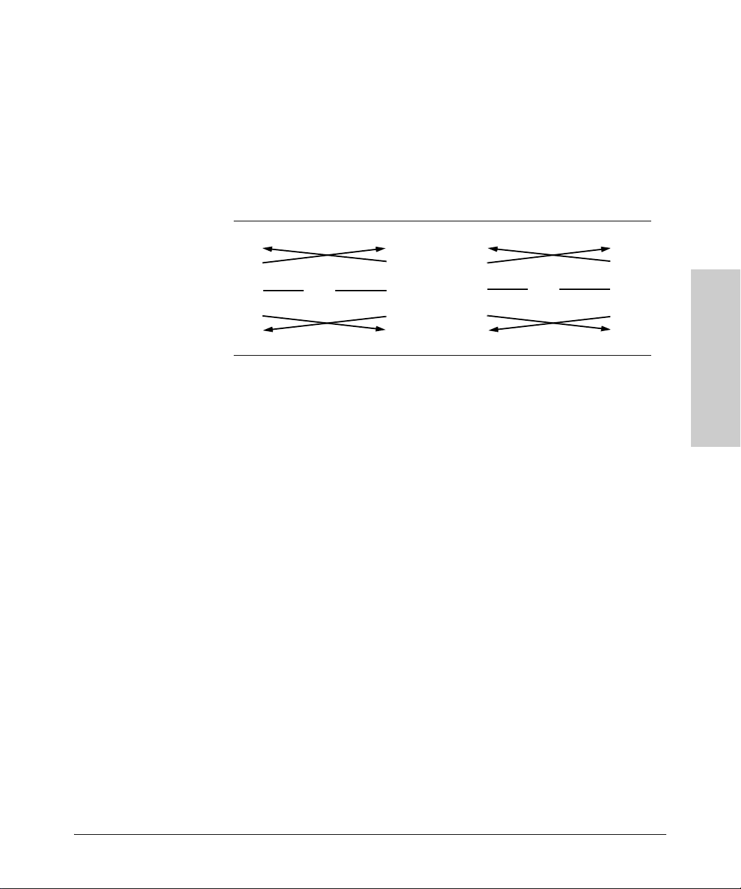
Crossover Twisted-Pair Cable for
10 Mbps or 100 Mbps Network Connection
Because the 10/100 port on the access point supports auto-MDIX operation,
you can use either “straight-through” or “crossover” cable for network connections to PCs, servers, hubs, or switches.
Cable Diagram
Access Point Port and
Note Pins 1 and 2 on connector “A” must be wired as a twisted pair to pins 3 and 6
on connector “B”.
Pins 3 and 6 on connector “A” must be wired as a twisted pair to pins 1 and 2
on connector “B”.
Pins 4, 5, 7, and 8 are not used for transmitting or receiving data, although they
must be wired straight-through in the cable to support Power over Ethernet.
.
Network Cables
B-4
Pin Assignments
Access Point End (MDI) Computer, Transceiver, or
Signal Pins Pins Signal
receive +
receive transmit +
transmit -
1
2
3
6
Other MDI Port End
6
3
2
1
transmit transmit +
receive receive +
Page 50

Safety and EMC Regulatory Statements
Safety Information
Documentation r eference symbol. If the product is marked with this
!
symbol, refer to the product documentation to get more information
about the product.
C
WARNING A WARNING in the manual denotes a hazard that can cause injury
or death.
CAUTION A CAUTION in the manual denotes a hazard that can damage the
equipment or create a non-compliant condition.
Do not proceed beyond a WARNING or CAUTION notice until you
have understood the hazardous conditions and have taken appropriate steps.
Grounding
This product is a safety class I compliant product and has a protective earthing
terminal. There must be an uninterruptible safety earth ground from the main
power source to the product's power cord or supplied power cord set.
Whenever it is likely that the protection has been impaired, disconnect the
power cord until the ground has been restored.
For LAN cable grounding:
■ If your LAN covers an area served by more than one power distribu-
tion system, be sure their safety grounds are securely interconnected.
■ LAN cables may occasionally be subject to hazardous transient volt-
ages (such as lightning or disturbances in the electrical utilities power
grid). Handle exposed metal components of the network with caution.
Servicing
There are no user-serviceable parts inside this product. Any servicing, adjustment, maintenance, or repair must be performed only by service-trained
personnel.
Safety and EMC Regulatory
Statements
This product does not have a power switch; it is powered on when the power
cord is plugged in.
C-1
Page 51

Safety and EMC Regulatory Statements
Safety Information
Regulatory Model Identification Number
For regulatory identification purposes, this product has been assigned a
Regulatory Model Number (RMN). The RMN for your product is RSVLC-
0501. The RMN should not be confused with the marketing name (Wireless
Enterprise Access Point 530) or the Product Number (J8986A, J8987A).
Statements
Safety and EMC Regulatory
C-2
Page 52

Safety and EMC Regulatory Statements
Informations concernant la sécurité
Informations concernant la sécurité
Symbole de référence à la documentation. Si le produit est marqué de
!
ce symbole, report ez-vous à la documentation du p roduit afin d'obtenir
des informations plus détaillées.
WARNING Dans la documentation, un WARNING indique un danger susceptible
CAUTION Un texte de mise en garde intitulé CAUTION indique un danger suscep-
Cet appareil est un produit de classe I et possède une borne de mise à la terre. La source
d'alimentation principale doit être munie d'une prise de terre de sécurité installée aux
bornes du câblage d'entrée, sur le cordon d'alimentation ou le cordon de raccordement
fourni avec le produit. Lorsque cette protection semble avoir été endommagée,
débrancher le cordon d'alimentation jusqu'à ce que la mise à la terre ait été réparée.
Mise à la terre du câble de réseau local:
■ si votre réseau local s'étend sur une zone desservie par plus d'un système de
distribution de puissance, assurez-vous que les prises de terre de sécurité
soient convenablement interconnectées.
■ Les câbles de réseaux locaux peuvent occasionnellement être soumis à des
surtensions transitoires dangereuses (telles que la foudre ou des perturbations dans le réseau d'alimentation public). Manipulez les composants
métalliques du réseau avec précautions.
Aucune pièce contenue à l'intérieur de ce produit ne peut être réparée par l'utilisateur.
Tout dépannage, réglage, entretien ou réparation devra être confié exclusivement à un
personnel qualifié.
d'entraîner des dommages corporels ou la mort.
tible de causer des dommages à l'équipement.
Ne continuez pas au-delà d'une rubrique WARNING ou CAUTION avant
d'avoir bien compris les conditions présentant un danger et pris les
mesures appropriées.
Cet appareil ne comporte pas de commutateur principal ; la mise sous tension est
effectuée par branchement du cordon d'alimentation.
Safety and EMC Regulatory
Statements
C-3
Page 53

Safety and EMC Regulatory Statements
Hinweise zur Sicherheit
Hinweise zur Sicherheit
!
Symbol für Dokumentationsverweis. Wenn das Produkt mit diesem
Symbol markiert ist, schlagen Sie bitte in der Produktdokumentation
nach, um mehr Informationen über das Produkt zu erhalten.
WARNING Eine WARNING in der Dokumentation symbolisiert eine Gefahr, die
CAUTION CAUTION in der Dokumentation symbolisiert eine Gefahr, die dis
Dies ist ein Gerät der Sicherheitsklasse I und verfügt über einen schützenden Erdungsterminal. Der Betrieb des Geräts erfordert eine ununterbrochene Sicherheitserdung
von der Hauptstromquelle zu den Geräteingabeterminals, den Netzkabeln oder dem
mit Strom belieferten Netzkabelsatz voraus. Sobald Grund zur Annahme besteht, daß
der Schutz beeinträchtigt worden ist, das Netzkabel aus der Wandsteckdose herausziehen, bis die Erdung wiederhergestellt ist.
Für LAN-Kabelerdung:
■ Wenn Ihr LAN ein Gebiet umfaßt, das von mehr als einem Stromverteilungs-
system beliefert wird, müssen Sie sich vergewissern, daß die
Sicherheitserdungen fest untereinander verbunden sind.
■ LAN-Kabel können gelegentlich gefährlichen Übergangsspannungen aus-
gesetzt werden (beispielsweise durch Blitz oder Störungen in dem
Starkstromnetz des Elektrizitätswerks). Bei der Handhabung exponierter
Metallbestandteile des Netzwerkes Vorsicht walten lassen.
Dieses Gerät enthält innen keine durch den Benutzer zu wartenden Teile. Wartungs-,
Anpassungs-, Instandhaltungs- oder Reparaturarbeiten dürfen nur von geschultem
Bedienungspersonal durchgeführt werden.
Verletzungen oder sogar Todesfälle verursachen kann.
Gerät beschädigen kann.
Fahren Sie nach dem Hinweis WARNING oder CAUTION erst fort,
nachdem Sie den Gefahrenzustand verstanden und die entsprechenden Maßnahmen ergriffen haben.
Dieses Gerät hat keinen Netzschalter; es wird beim Anschließen des Netzkabels
eingeschaltet.
Statements
Safety and EMC Regulatory
C-4
Page 54

Safety and EMC Regulatory Statements
Considerazioni sulla sicurezza
Considerazioni sulla sicurezza
Simbolo di riferimento alla documentazione. Se il prodotto è contras-
!
segnato da questo simbolo, fare riferimento alla documentazione sul
prodotto per ulteriori informazioni su di esso.
WARNING La dicitura WARNING denota un pericolo che può causare lesioni o
morte.
CAUTION La dicitura CAUTION denota un pericolo che può danneggiare le
attrezzature.
Non procedere oltre un avviso di WARNING o di CAUTION prima di
aver compreso le condizioni di rischio e aver provveduto alle misure
del caso.
Questo prodotto è omologato nella classe di sicurezza I ed ha un terminale protettivo
di collegamento a terra. Dev'essere installato un collegamento a terra di sicurezza, non
interrompibile che vada dalla fonte d'alimentazione principale ai terminali d'entrata,
al cavo d'alimentazione oppure al set cavo d'alimentazione fornito con il prodotto.
Ogniqualvolta vi sia probabilità di danneggiamento della protezione, disinserite il cavo
d'alimentazione fino a quando il collegaento a terra non sia stato ripristinato.
Per la messa a terra dei cavi LAN:
■ se la vostra LAN copre un'area servita da più di un sistema di distribuzione
elettrica, accertatevi che i collegamenti a terra di sicurezza siano ben collegati
fra loro;
■ i cavi LAN possono occasionalmente andare soggetti a pericolose tensioni
transitorie (ad esempio, provocate da lampi o disturbi nella griglia d'alimentazione della società elettrica); siate cauti nel toccare parti esposte in metallo
della rete.
Nessun componente di questo prodotto può essere riparato dall'utente. Qualsiasi
lavoro di riparazione, messa a punto, manutenzione o assistenza va effettuato esclusivamente da personale specializzato.
Questo apparato non possiede un commutatore principale; si mette scotto tensione
all'inserirsi il cavo d'alimentazione.
Safety and EMC Regulatory
C-5
Statements
Page 55

Safety and EMC Regulatory Statements
Consideraciones sobre seguridad
Consideraciones sobre seguridad
Símbolo de referencia a la documentación. Si el producto va
!
marcado con este símbolo, consultar la documentación del
producto a fin de obtener mayor información sobre el producto.
WARNING Una WARNING en la documentación señala un riesgo que podría
CAUTION Una CAUTION en la documentación señala un riesgo que podría
Este aparato se enmarca dentro de la clase I de seguridad y se encuentra protegido por
una borna de puesta a tierra. Es preciso que exista una puesta a tierra continua desde
la toma de alimentación eléctrica hasta las bornas de los cables de entrada del aparato,
el cable de alimentación o el juego de cable de alimentación suministrado. Si existe la
probabilidad de que la protección a tierra haya sufrido desperfectos, desenchufar el
cable de alimentación hasta haberse subsanado el problema.
Puesta a tierra del cable de la red local (LAN):
■ Si la LAN abarca un área cuyo suministro eléctrico proviene de más de una
red de distribución de electricidad, cerciorarse de que las puestas a tierra
estén conectadas entre sí de modo seguro.
■ Es posible que los cables de la LAN se vean sometidos de vez en cuando a
voltajes momentáneos que entrañen peligro (rayos o alteraciones en la red
de energía eléctrica). Manejar con precaución los componentes de metal de
la LAN que estén al descubierto.
Este aparato no contiene pieza alguna susceptible de reparación por parte del usuario.
Todas las reparaciones, ajustes o servicio de mantenimiento debe realizarlos solamente el técnico.
resultar en lesiones o la muerte.
resultar en averías al equipo.
No proseguir d espués de un símbolo de WARNING o CAUTION hast a
no haber entendido las condiciones peligrosas y haber tomado las
medidas apropiadas.
Este producto no tiene interruptor de potencia; se activa cuando se enchufa el cable
de alimentación.
Statements
Safety and EMC Regulatory
C-6
Page 56

Safety and EMC Regulatory Statements
Safety Information (Japan)
Safety Information (Japan)
C-7
Safety and EMC Regulatory
Statements
Page 57

Safety and EMC Regulatory Statements
Safety Information (China)
Safety Information (China)
Statements
Safety and EMC Regulatory
C-8
Page 58

Safety and EMC Regulatory Statements
EMC Regulatory Statements
EMC Regulatory Statements
Notice for U.S.A.
Manufacturer’s FCC Declaration of Conformity Statement
Tested to Comply
with FCC Standards
Product No: J8986A
Regulatory Model No: RSVLC-0501
Manufacturer: Hewlett-Packard Company
3000 Hanover Street
Palo Alto, CA 94304-1185 USA
Phone: 650-857-1501
For questions regarding this declaration, contact the Product Regulations
Manager at the above address or phone number.
This device complies with Part 15 of the FCC rules. Operation is subject to
the following two conditions: 1) this device may not cause harmful interference, and 2) this device must accept any interference received, including
interference that may cause undesired operation.
This equipment has been tested and found to comply with the limits for a Class
B digital device, pursuant to Part 15 of the FCC Rules. These limits are
designed to provide reasonable protection against harmful interference in a
residential installation. This equipment generates, uses and can radiate radio
frequency energy and, if not installed and used in accordance with instructions, may cause harmful interference to radio communications. However,
there is no guarantee that the interference will not occur in a particular
installation. If this equipment does cause harmful interference to radio or
television reception, which can be determined by turning the equipment off
and on, the user is encouraged to try to correct the interference by one or more
of the following measures:
■ Reorient the receiving antenna
■ Increase the separation between the equipment and receiver
■ Connect the equipment into an outlet on a circuit different from that to
which the receiver is connected
■ Consult the dealer or an experienced radio/TV technician for help
Safety and EMC Regulatory
Statements
C-9
Page 59

Safety and EMC Regulatory Statements
EMC Regulatory Statements
The FCC requires the user to be notified that any changes or modifications
made to the device that are not expressly approved by the Hewlett-Packard
Company may void the user’s authority to operate the equipment.
If this device is going to be operated in the 5.15 ~ 5.25 GHz frequency range,
then it is restricted to an indoor environment only.
!
Notice for Canada
This device complies with the limits for a Class B digital device and conforms
to Industry Canada standard ICES-003. Products that contain a radio transmitter comply with Industry Canada standard RSS210 and are labeled with an
IC approval number.
Warning: Exposure to Radio Frequency Radiation
The radiated output power of this device is below the FCC radio
exposure limits. Nevertheless, the device should be used in such
a manner that the potential for human contact during normal
operation is minimized. To avoid the possibility of exceeding the
FCC radio frequency exposure limits, human proximity to the
antennas should not be less than 25 cm (10 inches) during normal
operation.
Cet appareil numérique de la classe B est conforme à la norme ICES-003 de
Industry Canada. La radio sans fil de ce dispsitif est conforme à la certification
RSS 210 de Industry Canada et est étiquetée avec un numéro d’approbation IC.
This device complies with the Class B limits of Industry Canada. Operation is
subject to the following two conditions: 1) this device may not cause harmful
interference, and 2) this device must accept interference received, including
interference that may cause undesired operation.
This device has been designed to operate with the antennas listed in this
section, having a maximum gain of 13.8 dBi. Antennas not included in this list
or having a gain greater that 13.8 dBi are strictly prohibited for use with this
device. The required impedance is 50 ohms.
To reduce potential radio interference with other users, the antenna type and
its gain should be so chosen that the equivalent isotropically radiated power
(EIRP) is not more than that required for successful communication.
Statements
Safety and EMC Regulatory
C-10
If this device is going to be operated in the 5.15 ~ 5.25 GHz frequency range,
then it is restricted to an indoor environment only.
Page 60

Safety and EMC Regulatory Statements
EMC Regulatory Statements
Notice for European Community
This device complies with the EMC Directive 89/336/EEC, Low Voltage Directive 73/23/EEC and R&TTE Directive 1999/5/EC. Compliance with these directives implies conformity to harmonized European standards (European
Norms) that are listed on the EU Declaration of Conformity that has been
issued by HP for this device.
Countries of Operation & Conditions of Use
This device may be used in the following EU and EFTA countries: Austria,
Belgium, Cyprus, Czech Republic, Denmark, Estonia, Finland, France,
Germany, Greece, Hungary, Iceland, Ireland, Italy, Latvia, Liechtenstein,
Lithuania, Luxembourg, Malta , Netherlands, Norway, Poland, Portugal, Slovak
Republic, Slovenia, Spain, Sweden, Switzerland and the United Kingdom.
Requirements for indoor vs. outdoor operation, licensing and allowed channels of operation apply in some countries as described below.
Note The user must use the configuration utility provided with this device to ensure
the channels of operation are in conformance with the spectrum usage rules
for EU and EFTA countries as described below.
2.4 GHz Operation:
■ This device may be operated indoors or outdoors in all EU and EFTA
countries using the 2.4GHz band (Channels 1 - 13), except where noted
below.
■ In Italy, a license is required for outdoor use. Verify with your dealer or
directly with the General Direction for Frequency Planning and Management (Direzione Generale Pianificazione e Gestione Frequenze).
E’necessaria una concessione ministeriale anche per l’uso del prodotto.
Verifici per favore con il proprio distributore o direttamente presso la
Direzione Generale Pianificazione e Gestione Frequenze.
■ In France, this device may use the entire 2400 - 2483.5 MHz band (Channels
1 through 13) for indoor applications. For outdoor use, only the 2454 -
2483.5 MHz frequency band (Channels 10 through 13) may be used. For
the latest requirements, see http://www.art-telecom.fr.
L’utilisation de cet equipement (2.4GHz wireless LAN) est soumise à
certaines restrictions: cet equipement peut être utilisé à l’interieur d’un
batiment en utilisant toutes les frequences de 2400 a 2483.5MHz (Chaine
Safety and EMC Regulatory
Statements
C-11
Page 61

Safety and EMC Regulatory Statements
EMC Regulatory Statements
1-13). Pour une utilisation en environnement exterieur, vous devez utiliser
les frequencies comprises entre 2454 a 2483.5-MHz (Chaine 10-13). Pour
les dernières restrictions, voir http://www.art-telecom.fr.
5 GHz Operation:
■ This device requires the user or installer to properly enter the current
country of operation in the 5 GHz Radio Configuration Window as
described in the Management and Configuration Guide, before operating this device.
■ This device will automatically limit the allowable channels determined by
the current country of operation. Incorrectly entering the country of
operation may result in illegal operation and may cause harmful interference to other systems. The user is obligated to ensure the device is
operating according to the channel limitations, indoor/outdoor restrictions and license requirements for each European Community country as
described in this document.
■ This device employs a radar detection feature required for European
Community and EFTA country operation in the 5 GHz band. This feature
is automatically enabled when the country of operation is correctly
configured for any European Community or EFTA country. The presence
of nearby radar operation may result in temporary interruption of operation of this device. The radar detection feature will automatically restart
operation on a channel free of radar.
■ This device is restricted to indoor use when operated in EU and EFTA
countries using the 5.15-5.35 GHz band (Channels 36, 40, 44, 48, 52, 56, 60
and 64). See the table below for the allowed 5 GHz channels in each band.
Operation Using 5 GHz Channels in the European Community
The user/installer must use the provided configuration utility to check the
current channel of operation and make necessary configuration changes to
ensure operation occurs in conformance with European National spectrum
usage laws as described below and elsewhere in this document.
Frequency Band
(MHz)
5150 - 5250 36, 40, 44, 48 Indoor use only 200
5250 - 5350 52, 56, 60, 64 Indoor use only 200
5470 - 5725 100, 104, 108, 112,
Statements
Allowed Channels Usage Maximum EIRP
(mW)
Indoor or outdoor use 1000
116, 120, 124, 128,
132, 136, 140
Safety and EMC Regulatory
C-12
Page 62

Safety and EMC Regulatory Statements
EMC Regulatory Statements
Transmit Power Control (TPC) for 5GHz Operation
This device employs Transmit Power Control (TPC) to reduce the potential
for interference to other communication systems operating in the 5GHz
frequency bands. The TPC feature implemented in this Wireless LAN device
must be configured by the end-user when operating in any European Community or EFTA country. The end-user must follow the procedures explained in
the Management and Configuration Guide in order to operate this device in
accordance with European regulatory requirements for Transmit Power
control.
Note The TPC procedure should be repeated when relocating this wireless device
within the current wireless network or to a wireless network in a new location.
Supported Antennas
The following table lists the available antennas for the ProCurve RSVLC-0501:
HP Product
Number
J8441A
J8444A
J8448A*
J8997A
Power (dBm) Frequency
Module 1_bg
Module 2_abg
Module 1_bg
Module 2_abg
Module 1_bg
Module 2_abg
Module 1_bg
Module 2_abg
802.11b: 22
802.11g: 19.5
802.11b: 21.5
802.11g: 18.5
802.11b: 22
802.11g: 19.5
802.11b: 21.5
802.11g: 18.5
802.11b: 20.5
802.11g: 16.5
802.11b: 20
802.11g: 16
802.11b: 22
802.11g: 20.5
802.11a: 17
802.11b: 22.5
802.11g: 19.5
Antenna Type Actual
Range (GHz)
2.4-2.5 Omni 4.4
2.4-2.5 Omni 7.4
2.4-2.5 Yagi 13.8
2.4-2.5
4.9-5.99
Omni 3/4
Gain (dBi)
Safety and EMC Regulatory
Statements
C-13
Page 63

Safety and EMC Regulatory Statements
EMC Regulatory Statements
HP Product
Number
Module 1_bg
J8999A
Module 2_abg
J8998A Module 2_abg 802.11a: 17 5.15-5.875 Omni 6.3
J9000A Module 2_abg 802.11a: 17 5.15-5.875 Directional 13.3
* A point-to-point antenna, accompanied with a pigtail cable, a 10 ft extension cable (model
LMR-400), and a lightning arrester, which should be connected.
Power (dBm) Frequency
802.11b: 22
802.11g: 18.5
802.11a: 17
802.11b: 22
802.11g: 18.5
Range (GHz)
2.4-2.5
4.9-5.99
Antenna Type Actual
Gain (dBi)
Directional 6.9/7.7
CAUTION ■ When using antennas outdoors, a lightning arrestor is required for light-
ning protection. Consider placing the lightning arrestor immediately
before the antenna cable enters the building. HP offers a lightning arrestor
as an accessory; it is orderable under HP product number J8996A.
■ All HP ProCurve devices are designed to be compliant with the rules and
regulations in locations they are sold and will be labeled as required. Any
changes or modifications to HP ProCurve Equipment, not expressly
approved by HP, could void the user’s authority to operate this device.
Use only antennas approved for use with this device. Unauthorized
antennas, modifications, or attachments could cause damage and may
violate local radio regulations in your region.
■ When using external antennas, users must ensure that the combined
transmit power and antenna gain does not violate the maximum Equivalent Isotropic Radiated Power (EIRP) for your region. Information on
configuring this device to operate in a compliant manner can be found in
the Management and Configuration Guide.
Statements
Safety and EMC Regulatory
C-14
Page 64

EU Declaration of Conformity
TO BE INCLUDED LATER
Safety and EMC Regulatory Statements
EMC Regulatory Statements
C-15
Safety and EMC Regulatory
Statements
Page 65

Safety and EMC Regulatory Statements
EMC Regulatory Statements
Notice for Japan
Notice for Taiwan
DGT LPD (Low Power Device) Statement:
Statements
Safety and EMC Regulatory
C-16
Page 66

Notice for Korea
Safety and EMC Regulatory Statements
EMC Regulatory Statements
C-17
Safety and EMC Regulatory
Statements
Page 67

— This page is intentionally unused. —
Page 68

D
Recycle Statements
Waste Electrical and Electronic
Equipment (WEEE) Statements
Disposal of Waste Equipment by Users in Private Household in the European Union
This symbol on the product or on its packaging indicates that this product must not be disposed of with
your other household waste. Instead, it is your responsibility to dispose of your waste equipment by
handing it over to a designated collection point for the recycling of waste electrical and electronic
equipment. The separate collection and recycling of your waste equipment at the time of disposal will
help to conserve natural reso urces and ensure that it is recycled in a manner that protects human h ealth
and the environment. For more information about where you can drop off your waste equipment for
recycling, please contact your local city office, your household waste disposal service or the shop where
you purchased the product.
Likvidace zařízení soukromými domácími uživateli v Evropské unii
Tento symbol na produktu nebo balení označuje výrobek, který nesmí být vyhozen spolu s ostatním
domácím odpadem. Povinností uživatele je předat takto označený odpad na předem určené sběrné
místo pro recyklaci elektrických a elektronických zařízení. Okamžité třídění a recyklace odpadu
pomůže uchovat přírodní prostředí a zajistí takový způsob recyklace, který ochrání zdraví a životní
prostředí člověka. Další informace o možnostech odevzdání odpadu k recyklaci získáte na
příslušném obecním nebo městském úřadě, od firmy zabývající se sběrem a svozem odpadu nebo v
obchodě, kde jste produkt zakoupili.
Recycle Statements
Bortskaffelse af affald fra husstande i den Europæiske Union
Hvis produktet eller dets emballage er forsynet med dette symbol, angiver det, at produktet ikke må
bortskaffes med andet almindeligt husholdningsaffald. I stedet er det dit ansvar at bortskaffe kasseret
udstyr ved at aflevere det på den kommunale genbrugsstation, der forestår genvinding af kasseret
elektrisk og elektronisk udstyr. Den centrale modtagelse og genvinding af kasseret udstyr i forbindelse
med bortskaffelsen bidrager til bevarelse af naturlige ressourcer og sikrer, at udstyret genvindes på en
måde, der beskytter både mennesker og miljø. Yderligere oplysninger om, hvor du kan aflevere kasseret
udstyr til genvinding, kan du få hos kommune n, den lokale genbrugsstation eller i den butik, hvor du købte
produktet.
Seadmete jäätmete kõrvaldamine eramajapidamistes Euroopa Liidus
See tootel või selle pakendil olev sümbol näitab, et kõnealust toodet ei tohi koos teiste majapidamisjäätmetega kõrvaldada. Teie kohus on oma seadmete jäätmed kõrvaldada, viies need elektri- ja elektroonikaseadmete jäätmete ringlussevõtmiseks selleks ettenähtud kogumispunkti. Seadmete jäätmete eraldi
kogumine ja ringlussevõtmine kõrvaldamise ajal aitab kaitsta loodusvarasid ning tagada, et ringlussevõtmine toimub viisil, mis kaitseb inimeste tervist ning keskkonda. Lisateabe saamiseks selle kohta, kuhu
oma seadmete jäätmed ringlussevõtmiseks viia, võtke palun ühendust oma kohaliku linnakantselei,
majapidamisjäätmete kõrvaldamise teenistuse või kauplusega, kust Te toote ostsite.
D-1
Page 69

Recycle Statements
Έ
A
A
Waste Electrical and Electronic Equipment (WEEE) Statements
Laitteiden hävittäminen kotitalouksissa Euroopan unionin alueella
Jos tuotteessa tai sen pakkauksessa on tämä merkki, tuotetta ei saa hävittää kotitalousjätteiden mukana.
Tällöin hävitettävä laite on toimitettava sähkölaitteiden ja elektronisten laitteiden kierrätyspisteeseen.
Hävitettävien laitteiden erillinen käsittely ja kierrätys auttavat säästämään luonnonvaroja ja
varmistamaan, että laite kierrätetään tavalla, joka estää terveyshaitat ja suojelee luontoa. Lisätietoja
paikoista, joihin hävitettävät laitteet voi toimittaa kierrätettäväksi, saa ottamalla yhteyttä jätehuoltoon tai
liikkeeseen, josta tuote on ostettu.
Élimination des appareils mis au rebut par les ménages dans l'Union européenne
Recycle Statements
Le symbole apposé sur ce produit ou sur son emballage indique que ce produit ne doit pas être jeté avec
les déchets ménagers ordinaires. Il est de votre responsabilité de mettre au rebut vos appareils en les
déposant dans les centres de collecte publique désignés pour le recyclage des équipements électriques
et électroniques. La collecte et le recyclage de vos appareils mis au rebut indépendamment du reste
des déchets contribue à la préservation des ressources naturelles et garantit que ces appareils seront
recyclés dans le respect de la santé humaine et de l'environnement. Pour obtenir plus d'informations
sur les centres de collecte et de recyclage des appareils mis au rebut, veuillez contacter les autorités
locales de votre région, les services de collecte des ordures ménagères ou le magasin dans lequel vous
avez acheté ce produit.
Entsorgung von Altgeräten aus privaten Haushalten in der EU
Das Symbol auf dem Produkt oder seiner Verpackung weist darauf hin, dass das Produkt nicht über den
normalen Hausmüll entsorgt werden darf. Benutzer sind verpflichtet, die Altgeräte an einer Rücknahmestelle für Elektro- und Elektronik-Altgeräte abzugeben. Die getrennte Sammlung und ordnungsgemäße Entsorgung Ihrer Altgeräte trägt zur Erhaltung der natürlichen Ressourcen bei und garantiert
eine Wiederverwertung, die die Gesundheit des Menschen und die Umwelt schützt. Informationen dazu,
wo Sie Rücknahmestellen für Ihre Altgeräte finden, erhalten Sie bei Ihrer Stadtverwaltung, den örtlichen
Müllentsorgungsbetrieben oder im Geschäft, in dem Sie das Gerät erworben haben
Απόρριψη άχρηστου εξοπλισμού από χρήστες σε ιδιωτικά νοικοκυριά στην Ευρωπαϊκή
νωση
Το σύμβολο αυτό στο προϊόν ή τη συσκευασία του υποδεικνύει ότι το συγκεκριμένο προϊόν δεν
πρέπει να διατίθεται μαζί με τα άλλα οικιακά σας απορρίμματα. Αντίθετα, είναι δική σας ευθύνη να
απορρίψετε τον άχρηστο εξοπλισμό σας παραδίδοντάς τον σε καθορισμένο σημείο συλλογής για την
ανακύκλωση άχρηστου ηλεκτρικού και ηλεκτρονικού εξοπλισμού
ανακύκλωση του άχρηστου εξοπλισμού σας κατά την απόρριψη θα συμβάλει στη διατήρηση των
φυσικών πόρων και θα διασφαλίσει ότι η ανακύκλωση γίνεται με τρόπο που προστατεύει την
ανθρώπινη υγεία και το περιβάλλον. Για περισσότερες πληροφορίες σχετικά με το πού μπορείτε να
παραδώσετε τον άχρηστο εξοπλισμό σας
γραφείο, την τοπική υπηρεσία διάθεσης οικιακών απορριμμάτων ή το κατάστημα όπου αγοράσατε το
προϊόν.
Készülékek magánháztartásban történő selejtezése az Európai Unió területén
készüléken, illetve a készülék csomagolásán látható azonos szimbólum annak jelzésére szolgál,
hogy a készülék a selejtezés során az egyéb háztartási hulladéktól eltérő módon kezelendő. A
vásárló a hulladékká vált készüléket köteles a kijelölt gyűjtőhelyre szállítani az elektromos és
elektronikai készülékek újrahasznosítása céljából. A hulladékká vált készülékek selejtezéskori
begyűjtése és újrahasznosítása hozzájárul a természeti erőforrások megőrzéséhez, valamint
biztosítja a selejtezett termékek környezetre és emberi egészségre nézve biztonságos feldolgozását.
begyűjtés pontos helyéről bővebb tájékoztatást a lakhelye szerint illetékes önkormányzattól, az
illetékes szemételtakarító vállalattól, illetve a terméket elárusító helyen kaphat.
για ανακύκλωση, επικοινωνήστε με το αρμόδιο τοπικό
. Η ξεχωριστή συλλογή και
D-2
Page 70

Waste Electrical and Electronic Equipment (WEEE) Statements
A
V
Recycle Statements
Smaltimento delle apparecchiature da parte di privati nel territorio dell'Unione Europea
Questo simbolo presente sul prodotto o sulla sua confezione indica che il prodotto non può essere
smaltito insieme ai rifiuti domestici. È responsabilità dell'utente smaltire le apparecchiature consegnandole presso un punto di raccolta designato al riciclo e allo smaltimento di apparecchiature elettriche ed
elettroniche. La raccolta differenziata e il corretto riciclo delle apparecchiature da smaltire permette di
proteggere la salute degli individui e l'ecosistema. Per ulteriori informazioni relative ai punti di raccolta
delle apparecchiature, contattare l'ente locale per lo smaltimento dei rifiuti, oppure il negozio presso il
quale è stato acquistato il prodotto.
Nolietotu iekārtu iznīcināšanas noteikumi lietotājiem Eiropas Savienības privātajās
mājsaimniecībās
Šāds simbols uz izstrādājuma vai uz tā iesaiņojuma norāda, ka šo izstrādājumu nedrīkst izmest kopā ar
citiem sadzīves atkritumiem. Jūs atbildat par to, lai nolietotās iekārtas tiktu nodotas speciāli iekārtotos
punktos, kas paredzēti izmantoto elektrisko un elektronisko iekārtu savākšanai otrreizējai pārstrādei.
tsevišķa nolietoto iekārtu savākšana un otrreizējā pārstrāde palīdzēs saglabāt dabas resursus un
garantēs, ka šīs iekārtas tiks otrreizēji pārstrādātas tādā veidā, lai pasargātu vidi un cilvēku veselību.
Lai uzzinātu, kur nolietotās iekārtas var izmest otrreizējai pārstrādei, jāvēršas savas dzīves vietas
pašvaldībā, sadzīves atkritumu savākšanas dienestā vai veikalā, kurā izstrādājums tika nopirkts.
artotojų iš privačių namų ūkių įrangos atliekų šalinimas Europos Sąjungoje
Šis simbolis ant gaminio arba jo pakuotės rodo, kad šio gaminio šalinti kartu su kitomis namų ūkio
atliekomis negalima. Šalintinas įrangos atliekas privalote pristatyti į specialią surinkimo vietą elektros ir
elektroninės įrangos atliekoms perdirbti. Atskirai surenkamos ir perdirbamos šalintinos įrangos atliekos
padės saugoti gamtinius išteklius ir užtikrinti, kad jos bus perdirbtos tokiu būdu, kuris nekenkia žmonių
sveikatai ir aplinkai. Jeigu norite sužinoti daugiau apie tai, kur galima pristatyti perdirbtinas įrangos
atliekas, kreipkitės į savo seniūniją, namų ūkio atliekų šalinimo tarnybą arba parduotuvę, kurioje
įsigijote gaminį.
Recycle Statements
Verwijdering van afgedankte apparatuur door privé-gebruikers in de Europese Unie
Dit symbool op het product of de verpakking geeft aan dat dit product niet mag worden gedeponeerd bij
het normale huishoudelijke afval. U bent zelf verantwoordelijk voor het inleveren van uw afgedankte
apparatuur bij een inzamelingspunt voor het recyclen van oude elektrische en elektronische apparatuur.
Door uw oude apparatuur apart aan te bieden en te recyclen, kunnen natuurlijke bronnen worden
behouden en kan het materiaal worden hergebruikt op een manier waarmee de volksgezondheid en het
milieu worden beschermd. Neem contact op met uw gemeente, het afvalinzamelingsbedrijf of de winkel
waar u het product hebt gekocht voor meer informatie over inzamelingspunten waar u oude apparatuur
kunt aanbieden voor recycling.
Pozbywanie się zużytego sprzętu przez użytkowników w prywatnych gospodarstwach
domowych w Unii Europejskiej
Ten symbol na produkcie lub jego opakowaniu oznacza, że produktu nie wolno wyrzucać do zwykłych
pojemników na śmieci. Obowiązkiem użytkownika jest przekazanie zużytego sprzętu do
wyznaczonego punktu zbiórki w celu recyklingu odpadów powstałych ze sprzętu elektrycznego i
elektronicznego. Osobna zbiórka oraz recykling zużytego sprzętu pomogą w ochronie zasobów
naturalnych i zapewnią ponowne wprowadzenie go do obiegu w sposób chroniący zdrowie człowieka
i środowisko. Aby uzyskać więcej informacji o tym, gdzie można przekazać zużyty sprzęt do
recyklingu, należy się skontaktować z urzędem miasta, zakładem gospodarki odpadami lub sklepem,
w którym zakupiono produkt.
D-3
Page 71

Recycle Statements
Waste Electrical and Electronic Equipment (WEEE) Statements
Descarte de Lixo Elétrico na Comunidade Européia
Este símbolo encontrado no produto ou na embalagem indica que o produto não deve ser descartado
no lixo doméstico comum. É responsabilidade do cliente descartar o material usado (lixo elétrico),
encaminhando-o para um ponto de coleta para reciclagem. A coleta e a reciclagem seletivas desse
tipo de lixo ajudarão a conservar as reservas naturais; sendo assim, a reciclagem será feita de uma
forma segura, protegendo o ambiente e a saúde das pessoas. Para obter mais informações sobre locais
que reciclam ess e tipo de material, entre e m contato com o escritório da HP em sua cidade, com o s erviço
de coleta de lixo ou com a loja em que o produto foi adquirido.
Recycle Statements
Likvidácia vyradených zariadení v domácnostiach v Európskej únii
Symbol na výrobku alebo jeho balení označuje, že daný výrobok sa nesmie likvidovať s domovým
odpadom. Povinnosťou spotrebiteľa je odovzdať vyradené zariadenie v zbernom mieste, ktoré je
určené na recykláciu vyradených elektrických a elektronických zariadení. Separovaný zber a
recyklácia vyradených zariadení prispieva k ochrane prírodných zdrojov a zabezpečuje, že recyklácia
sa vykonáva spôsobom chrániacim ľudské zdravie a životné prostredie. Informácie o zberných
miestach na recykláciu vyradených zariadení vám poskytne miestne zastupiteľstvo, spoločnosť
zabezpečujúca odvoz domového odpadu alebo obchod, v ktorom ste si výrobok zakúpili.
Odstranjevanje odslužene opreme uporabnikov v zasebnih gospodinjstvih v Evropski uniji
Ta znak na izdelku ali njegovi embalaži pomeni, da izdelka ne smete odvreči med gospodinjske
odpadke. Nasprotno, odsluženo opremo morate predati na zbirališče, pooblaščeno za recikliranje
odslužene električne in elektronske opreme. Ločeno zbiranje in recikliranje odslužene opreme
prispeva k ohranjanju naravnih virov in zagotavlja recikliranje te opreme na zdravju in okolju neškodljiv
način. Za podrobnejše informacije o tem, kam lahko odpeljete odsluženo opremo na recikliranje, se
obrnite na pristojni organ, komunalno službo ali trgovino, kjer ste izdelek kupili.
Eliminación de residuos de equipos eléctricos y electrónicos por parte de usuarios particulares en la
Unión Europea
Este símbolo en el producto o en su envase indica que no debe eliminarse junto con los desperdicios
generales de la casa. Es responsabilidad del usuario eliminar los residuos de este tipo depositándolos
en un "punto limpio" para el reciclado de residuos eléctricos y electrónicos. La recogida y el reciclado
selectivos de los residuos de aparatos eléctricos en el momento de su eliminación contribuirá a
conservar los recursos naturales y a garantizar el reciclado de estos residuos de forma que se proteja
el medio ambiente y la salud. Para obtener más información sobre los puntos de recogida de residuos
eléctricos y electrónicos para reciclado, póngase en contacto con su ayuntamiento, con el servicio de
eliminación de residuos domésticos o con el establecimiento en el que adquirió el producto.
Bortskaffande av avfallsprodukter från användare i privathushåll inom Europeiska Unionen
Om den här symbolen visas på produkten eller förpackningen betyder det att produkten inte får
slängas på samma ställe som hushållssopor. I stället är det ditt ansvar att bortskaffa avfallet genom att
överlämna det till ett uppsamlingsställe avsett för återvinning av avfall från elektriska och elektroniska
produkter. Separat insamling och återvinning av avfallet hjälper till att spara på våra naturresurser och
gör att avfallet återvinns på ett sätt som skyddar människors hälsa och miljön. Kontakta ditt lokala
kommunkontor, din närmsta återvinningsstation för hushållsavfall eller affären där du köpte produkten
för att få mer information om var du kan lämna ditt avfall för återvinning.
D-4
Page 72

Index
Numerics
10/100Base-TX
connections, length limitations … 2-4
ports, cables used with … 2-4
10/100Base-TX port
location on access point … 1-5
A
access point
connecting to a power source … 2-11
description … 1-1
downloading new software … 5-10
electrical specifications … A-1
emmissions specifications … A-2
environmental specifications … A-1
external antenna options … 4-2
features … 1-9
included parts … 2-1
LED descriptions … 1-4
mounting on a wall … 2-7, 2-9
mounting on horizontal surface … 2-11
physical specifications … A-1
top panel description … 1-3
access point operation
verifying after installation … 2-5
antennas
external options … 4-2
location on access point … 1-5
auto MDI/MDI-X operation … B-3
Auxiliary port
description … 1-8
location on access point … 1-8
B
back of access point
10/100Base-TX port … 1-5
Auxiliary port … 1-8
Clear button … 1-8
console port … 1-6
description … 1-5
lock … 1-6
network port … 1-6
power connector … 1-6
Reset button … 1-7
basic access point configuration
command line interface … 3-2
basic troubleshooting tips … 5-1
blinking LEDs
error indications … 5-3
buttons
Clear button … 1-8
Reset button … 1-7
C
cables
10/100Base-TX connections … 2-4
connecting cables to the access point
port … 2-12
effects of non-standard cables … 5-2
infrastructure requirements … 2-4
length limitations … 2-4
required types … 2-4, 4-2
serial, for direct console connection … 2-14
cables, twisted pair
access point-to-computer connection … B-3
access point-to-switch or hub connection … B-4
category 3, 4, 5 … B-2
cross-over cable pin-out … B-4
MDI-X to MDI connections … B-3
MDI-X to MDI-X connections … B-4
pin-outs … B-3
straight-through cable pin-out … B-3
cables, twisted-pair
wiring rules … B-2
cables, twisted-pair connector pin-outs … B-2
Index
Index – 1
Page 73

cabling infrastructure … 2-4
Clear button
description … 1-8
location on access point … 1-8
to delete password protection … 3-7
CLI prompt, console
displaying … 2-15
command line interface
key command descriptions … 3-6
configuration
command line interface … 3-2
DHCP … 3-2
IP address, manually … 3-2
restoring factory defaults … 5-8
connecting the access point to a power
source … 2-11
connector specifications … A-2
console
Index
checking messages during
troubleshooting … 5-6
command line interface … 3-2
displaying the CLI prompt … 2-15
features … 2-13
how to connect in-band … 2-13
how to connect out-of-band … 2-13
serial cable connection … 2-14
SSH access … 3-9
Telnet access … 3-8
terminal configuration … 2-13
console port
location on access point … 1-5–1-6
cross-over cable
pin-out … B-4
D
DC power connector
location on back of access point … 1-5
description
access point … 1-1
back of access point … 1-5
LEDs … 1-4
top of access point … 1-3
DHCP
automatic access point configuration … 3-2
for in-band access … 2-13
diagnostic tests … 5-6
checking the console messages … 5-6
checking the LEDs … 5-6
end-to-end connectivity … 5-7
testing the access point only … 5-6
testing twisted-pair cabling … 5-7
downloading new access point software … 5-10
E
electrical specifications, access point … A-1
EMC regulatory statements … C-9
emmissions specifications, access point … A-2
environmental specifications, access point … A-1
external antenna options … 4-2
F
factory default configuration, restoring … 5-8
features
access point … 1-9
console … 2-13
full-duplex fixed configuration
effects on network connections … 5-1
H
horizontal surface
mounting access point on … 2-11
I
in-band … 3-1
in-band console access
types of … 2-13
included parts … 2-1
installation
connecting the access point to a power
source … 2-11
horizontal surface mounting … 2-11
location considerations … 2-4, 4-3
network cable requirements … 2-4
precautions … 2-3
site preparation … 2-4
summary of steps … 2-2
wall mounting … 2-7, 2-9
2 – Index
Page 74

L
LAN LED … 1-4
behaviors … 1-4
LEDs
behavior during self test … 2-6
blinking definition … 1-4
checking during troubleshooting … 5-6
descriptions of … 1-4
error indications … 5-3
LAN … 1-4
location on access point … 1-3
on access point … 1-4
Power … 1-4
behavior during self test … 2-6
Self Test
behavior during self test … 2-6
Wireless … 1-4
length limitations
10/100Base-TX connections … 2-4
location for the access point, considerations … 2-4,
4-3
lock
location on access point … 1-6
M
MDI-X to MDI network cable … B-3
MDI-X to MDI-X network cable … B-4
mounting the access point
on a horizontal surface … 2-11
on a wall … 2-7, 2-9
precautions … 2-7
N
network cables
10/100Base-TX connections … 2-4
required types … 2-4
twisted-pair connector pin-outs … B-2
twisted-pair, wiring rules … B-2
network devices
connecting to the access point … 2-12
network ports
connecting to … 2-12
location on access point … 1-6
standards compliance … A-2
types of … 2-4, 4-2
non-standard network cables, effects … 5-2
O
out-of-band console access … 3-8
P
parts, included with the access point … 2-1
passwords
deleting with the Clear button … 3-7
if you lose the password … 3-7
physical specifications, access point … A-1
Ping test … 5-7
pin-outs
twisted-pair cables … B-2
PoE power connector
location on back of access point … 1-5
port LEDs
normal operation … 2-6
ports
10/100Base-TX, location on access point … 1-5
connecting to … 2-12
console … 2-13
network connections … 2-12
power connector … 1-6
Power LED … 1-4
behavior during self test … 2-6
behaviors … 1-4
location on access point … 1-3
power source
connecting the access point to … 2-11
precautions
mounting the access point … 2-3
power requirements … 2-3
preparing the installation site … 2-4
Proactive Network tools
diagnostics with … 5-5
R
recycle statements … D-1
regulatory statements … C-9
Reset button
description … 1-7
location on access point … 1-7
resetting the access point
factory default reset … 5-8
location of Reset button … 1-7
troubleshooting procedure … 5-6
Index
Index – 3
Page 75

S
safety and regulatory statements … C-1
safety specifications … A-2
self test
LED behavior during … 2-6
Power LED behavior … 2-6
Self Test LED
behavior during self test … 2-6
serial cable
for direct console connection … 2-14
sides of access point
antennas … 1-5
specifications
connectors … A-2
electrical … A-1
emmissions … A-2
environmental … A-1
physical … A-1
Index
safety … A-2
wireless … A-3
SSH access to the console … 3-9
straight-through cable
pin-out … B-3
summary
of access point installation … 2-2
of cables used with the access point … 2-4, 4-2
T
Telnet access to the console … 3-8
terminal configuration … 2-13
testing
access point operation … 5-6
access point-to-device communications … 5-7
checking the console messages … 5-6
checking the LEDs … 5-6
diagnostic tests … 5-6
end-to-end communications … 5-7
Ping test … 5-7
twisted-pair cabling … 5-7
tips for troubleshooting … 5-1
top of access point … 1-3
description … 1-3
LEDs … 1-4
topologies
effects of improper topology … 5-2
samples of … 2-16
troubleshooting … 5-1
basic tips … 5-1
checking the console messages … 5-6
checking the LEDs … 5-6
common network problems … 5-1
connecting to fixed full-duplex devices … 5-1
diagnostic tests … 5-6
effects of improper topology … 5-2
effects of non-standard cables … 5-2
Ping test … 5-7
Proactive Network tools … 5-5
restoring factory default configuration … 5-8
testing connections to other devices … 5-7
testing end-to-end communications … 5-7
testing the access point … 5-6
testing the twisted-pair cables … 5-7
twisted-pair cable
access point-to-computer connection … B-3
access point-to-switch or hub connection … B-4
cross-over cable pin-out … B-4
pin-outs … B-2– B-3
straight-through cable pin-out … B-3
testing … 5-7
V
VCCI compliance … C-16
VT-100 terminal
serial cable connection for … 2-14
W
wall
mounting access point on … 2-7, 2-9
warranty … 1-ii
wireless infrastructure
topology with … 2-17
wireless infrastructure for roaming clients
topology with … 2-18
Wireless LED … 1-4
behaviors … 1-4
wireless specifications … A-3
wiring rules for twisted-pair cables … B-2
4 – Index
 Loading...