

Page 1
Product Category: Personal Computers
Marketing Name / Model
[List multiple models if applicable.]
HP RP9 G1 AiO Retail System, Model 9015
1.0 Items Requiring Selective Treatment
Quantity
in product
Printed Circuit Boards (PCB) or Printed Circuit
Assemblies (PCA)
With a surface greater than 10 sq cm
1
Batteries
All types including standard alkaline and lithium coin
or button style batteries
1
Mercury-containing components
For example, mercury in lamps, display backlights,
scanner lamps, switches, batteries
0
Liquid Crystal Displays (LCD) with a surface greater
than 100 sq cm
Includes background illuminated displays with gas
discharge lamps N/A
2
Cathode Ray Tubes (CRT)
N/A
0
Capacitors / condensers (Containing PCB/PCT)
N/A
0
Electrolytic Capacitors / Condensers measuring
greater than 2.5 cm in diameter or height
N/A
0
External electrical cables and cords
N/A
1
Gas Discharge Lamps
N/A
0
Plastics containing Brominated Flame Retardants
already listed as a separate item above)
N/A
0
Components and parts containing toner and ink,
including liquids, semi-liquids (gel/paste) and toner
Include the cartridges, print heads, tubes, vent
chambers, and service stations. N/A
0
Components and waste containing asbestos
N/A
0
Components, parts and materials containing
refractory ceramic fibers
N/A
0
Product End-of-Life Disassembly Instructions
Purpose: The document is intended for use by end-of-life recyclers or treatment facilities. It provides the basic instructions
for the disassembly of HP products to remove components and materials requiring selective treatme nt, as defined by EU
directive 2002/96/EC, Waste Electrical and Electronic Equipment (WEEE).
1.1 Items listed below are classified as requiring selective treatment.
1.2 Enter the quantity of items contained within t he product which require selective treatment in the right column, as
applicable.
Item Description Notes
weighing > 25 grams (not including PCBs or PCAs
of items
included
EL-MF877-00 Page 1
Template Revision B
PSG instructions for this template are available at EL-MF877-01
Page 2

Components, parts and materials containing
radioactive substances
N/A
0
2.0 Tools Required
List the type and size of the tools that would typically be used to disassemble the product to a point whe re components
Tool Description
Tool Size (if
applicable)
T15 2.55-
3.00kgf.cm
2# 2.55-
3.00kgf.cm
Knife
Side Cutter
Star key wrench
3.0 Product Disassembly Process
and materials requiring selective treatment can be removed.
Hexagonal Screwdriver (T15)
Philips Screwdriver
Slotted Screwdriver
3.1 List the basic steps that should typically be f oll owed to remove components and materials requi ring selective treatment:
1. Disassembly process – Removing Back Cover
2. Disassembly process – Installing Wireless Card
3. Disassembly process –Installing DIMM
4. Disassembly process – Do not remove the HDD cage
5. Disassembly process -Remove the HDD cage
6. Disassembly process (CPU Installing)
7. Disassembly process (Installing back cover bracket)
8. Disassembly process (Assemble MCR, webcam, BIO reader (If necessary)
9. Disassembly process (MSR,Webcam,BIO)
10. Disassembly process (Assemble back cover)
11. Compact Stand Assembling (Without Power Supply)
12.
3.2 Optional Graphic. If the disassembly process is complex , insert a graphic illustration below to identify the items
contained in the product that require selective t reatment (with descriptions and arrows identifying locations).
1.Description of the sample submitted for assessment
EL-MF877-00 Page 2
Template Revision B
PSG instructions for this template are available at EL-MF877-01
Page 3
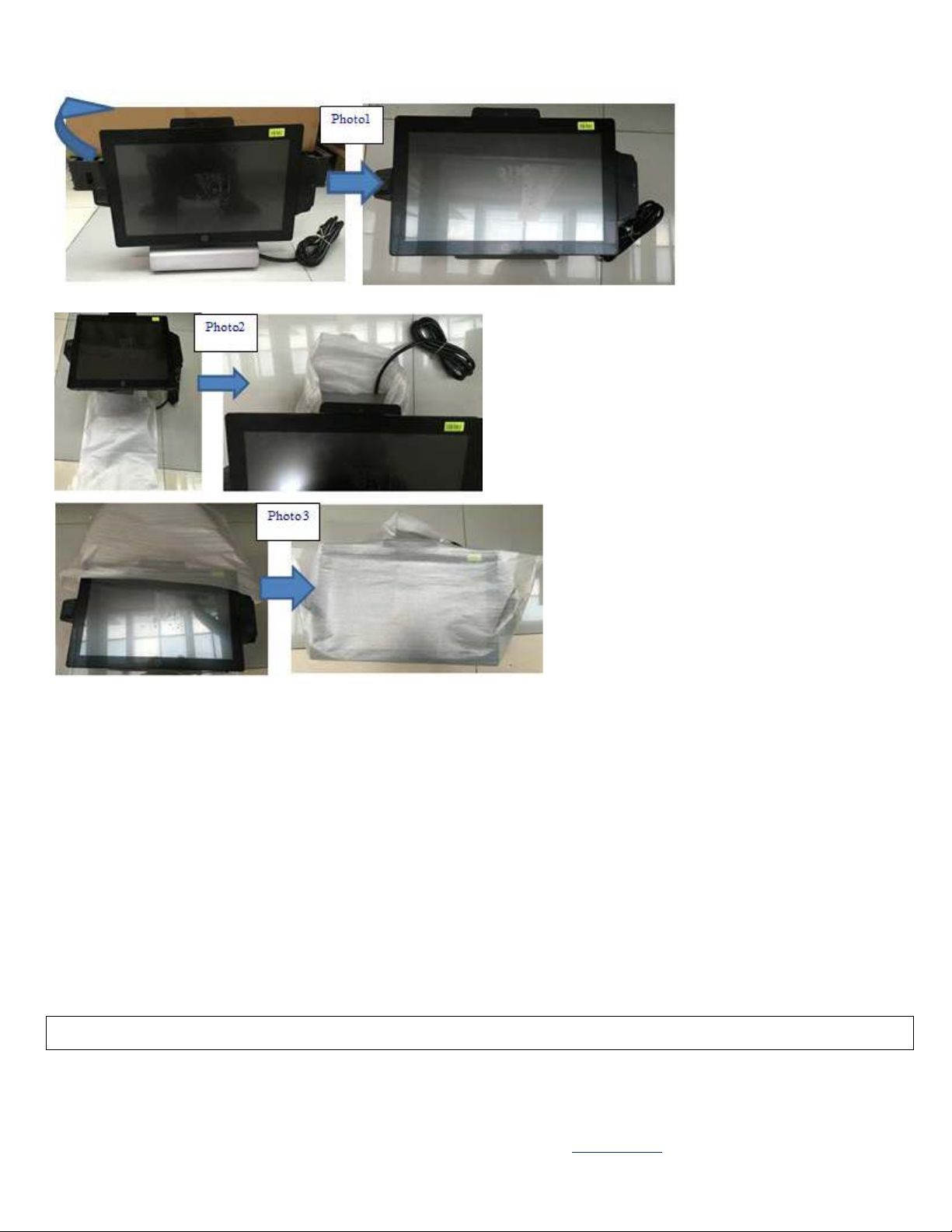
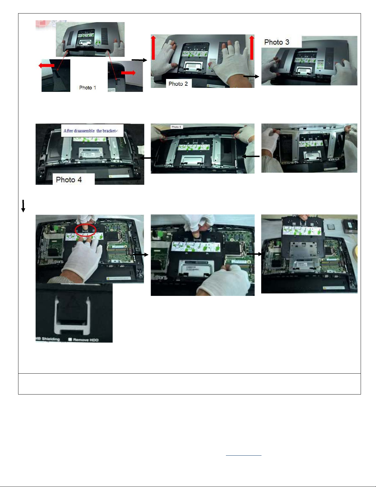
Disassembly process (Removing Back Cover)
Product view
EL-MF877-00 Page 3
Template Revision B
PSG instructions for this template are available at EL-MF877-01
Page 4
and 9.
Disassembly process (Installing Wireless Card)
Push the button on the middle bezel to
each side,see photo 1
Disassemble the
bracket, see photo 4
Disassemble the back cover by pulling
it upward and cover See photo 2.
Disassemble the bracket by the red
circle marked position and take off
the bracket, see photo 5
Take off the rear cover, see photo 3
Lift up the bracket,see photo 6
Pressing the visa cover hook and push
it to the direction show in the photo 7,8
EL-MF877-00 Page 4
Template Revision B
PSG instructions for this template are available at EL-MF877-01
Page 5
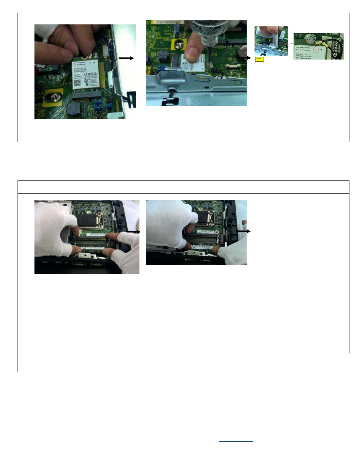
Install the wireless card atan angle of
45 degree.See photo 1
Screwdriver)See photo 2
Disassembly process (Installing DIMM)
at an angle of 45 degree.See photo 1
Disassembly process (Do not remove the HDD cage)
Fasten WIFI screw*1pcs as show in
photo 21.5 + /-0.2Kgf.cm Screw
driver: #1(Crosshead
Using pressing fixture to insert
cable in location“2”.Routing the
cable See photo3&4 Using pressing
fixture to insert cable in location“
1”.Routing the cable See photo3&4
Final cable routing for WLAN (
Photo 4)
Press the DIMM to confirm the DIMM
Take the DIMM and insert in DIMM slot
insert rightly See photo 2
EL-MF877-00 Page 5
Template Revision B
PSG instructions for this template are available at EL-MF877-01
Page 6

0.3kgf.cm
photo 4
Unlocking the 2 screws on the HDD
bracket see photo 1(T15)3.0+/-
Lift up the HDD bracket horizontally
and take down the HDD bracket, see
photo 2,3
Assemble the first SSD Card to the
SSD1 mark connector, and fix the
SSD card to the unit by lock the
screw , see photo 3
Assemble the second SSD Card to the
SSD2 mark connector, and fix the SSD
card to theunit by lock the screw ,see
EL-MF877-00 Page 6
Template Revision B
PSG instructions for this template are available at EL-MF877-01
Page 7

Disassembly process (Do not remove the HDD cage)
Assembling the HDD bracket to the unit
and lock the 2pcs screws, see photo 6
(T15)3.0+/-0.3kgf.cm
Assemble the first SSD Card to the
SSD1 mark(left position)connector
byone hand, and hold the
Mylar by another hand
see photo 1
Press the SSD to confirm it insert
rightly, and lock the screw to fix the SSD
on the MB, pull the Mylar aside at same
time, see photo 2
EL-MF877-00 Page 7
Template Revision B
PSG instructions for this template are available at EL-MF877-01
Page 8

HDD Module Processing and
Installing(if necessary)
See photo 2
See photo 4
Disassembly process (Remove the HDD cage)
Do not remove the HDD cage
Remove the tape on the HDD cage See
photo 1
Slide the HDD holder
splinter and assemble
the HDD to the HDD
cage rightly
Take 4 screw to lock
the HDD,(#1)1.5+/-0.3kgf.cm
Insert the SATA cable
to the HDD
See photo 5
Plug the HDD screw holder to the
hold on HDD cage
See photo 3
Check the connector is
inserted rightly
See photo 6
EL-MF877-00 Page 8
Template Revision B
PSG instructions for this template are available at EL-MF877-01
Page 9

Unscrew the 2 screws and remove
See photo4
See photo5
Disassembly process (CPU Installing)
the HDD bracket See photo 1 and
2
Take 4 screw to lock
the, (#1)1.5+/-
0.3kgf.cm
See photo 3
Install HDD in the unit
Check the Mylar connected to the MB
rightly, see photo 6
Insert the HDD SATA cable to HDD
EL-MF877-00 Page 9
Template Revision B
PSG instructions for this template are available at EL-MF877-01
Page 10

Put the CPU onto the CPU socket
shown on heat sink,see photo 7and 8
Disassembly process (Installing visa cover)
vertical by fixture, see photo 3 and 4
Open the CPU cover and take off
the plastic cover, check whether
there is PIN bend issue,See photo
2 for the bend pin
Put the CPU onto the CPU socket
vertical by fixture, see photo 3 and
4
Locking the CPU holder, and during this
process, the CPU holder clip will drop
from the CPU holder,take clip away from
the MB, see photo 5 and 6
Lock the heat sink to MB, and lock the
3 screws based on the sequence
EL-MF877-00 Page 10
Template Revision B
PSG instructions for this template are available at EL-MF877-01
Page 11

Disassembly process (Installing back cover bracket)
Disassembly process (Assemble MCR, webcam, BIO reader (If necessary)
Align the visa cover to the bracket
and press the clip to lock on to the
bracket see photo1
Push the rear cover to end , see picture 2
Confirm the visa cover locked well,
see photo 2 and 3
Double check the rear cover locked
well, see photo 4
Align the rear cover to the unit by
the two latch see photo 1
EL-MF877-00 Page 11
Template Revision B
PSG instructions for this template are available at EL-MF877-01
Page 12

Disassembly process (MSR,Webcam,BIO)
Unscrew the 2 screws on the 3
dummy covers, see photo 1 and 2
Put one screwdriver head into the screw
hole and pull the dummy cover outward,
use same method to dissemble the 3
dummy covers
Assemble the Webcam, MSR,BIO
to the unit and lock the two screw
red marked See Photo 4 Confirm the
Webcam, MSR,BIO assembled rightly
see photo 5
Lock the 2 screws,see photo 6
EL-MF877-00 Page 12
Template Revision B
PSG instructions for this template are available at EL-MF877-01
Page 13

After the MSR,Webcam, BIO
Compact Stand Assembling (Without Power Supply)
Disassembly process (Assemble back cover)
hooks are locked well See photo 4
assembled status,see photo 1
Put the back cover to the unit See
photo 1
Double check and confirm all the
EL-MF877-00 Page 13
Template Revision B
Push it towards
your self-direction
See photo 2
Assemble the back
cover to the unit,
and lock the hook
see photo 3
PSG instructions for this template are available at EL-MF877-01
Page 14

Assemble the bottom cover to the
stand,See photo 1~2
Assemble the stand to the unit
Lock each hook of the stand to the
unit VESA cover socket, 1 to 1, 2
to2 see photo 5
Assemble the bottom cover to the stand,
See photo 3
Check the 6 latches on the cover are no
damage, see photo 4
EL-MF877-00 Page 14
Template Revision B
PSG instructions for this template are available at EL-MF877-01
 Loading...