

Page 1

Hardware Reference Guide
HP RP9 G1 Retail System
Page 2

© Copyright 2015 HP Development Company,
L.P.
ENERGY STAR® is a registered mark owned by
the U.S. government. Microsoft and Windows
are either registered trademarks or trademarks
of Microsoft Corporation in the United States
and/or other countries.
The information contained herein is subject to
change without notice. The only warranties for
HP products and services are set forth in the
express warranty statements accompanying
such products and services. Nothing herein
should be construed as constituting an
additional warranty. HP shall not be liable for
technical or editorial errors or omissions
contained herein.
First Edition: October 2015
Document Part Number: 834295-001
Product notice
This guide describes features that are common
to most models. Some features may not be
available on your computer.
Not all features are available in all editions of
Windows 8. This computer may require
upgraded and/or separately purchased
hardware, drivers and/or software to take full
advantage of Windows 8 functionality. See
http://www.microsoft.com for details.
This computer may require upgraded and/or
separately purchased hardware and/or a DVD
drive to install the Windows 7 software and
take full advantage of Windows 7 functionality.
See http://windows.microsoft.com/en-us/
windows7/get-know-windows-7 for details.
Software terms
By installing, copying, downloading, or
otherwise using any software product
preinstalled on this computer, you agree to be
bound by the terms of the HP End User License
Agreement (EULA). If you do not accept these
license terms, your sole remedy is to return the
entire unused product (hardware and software)
within 14 days for a refund subject to the
refund policy of your place of purchase.
For any further information or to request a full
refund of the computer, please contact your
local point of sale (the seller).
Page 3

About This Book
This guide provides basic information for upgrading this computer model.
WARNING! Text set o in this manner indicates that failure to follow directions could result in bodily harm or
loss of life.
CAUTION: Text set o in this manner indicates that failure to follow directions could result in damage to
equipment or loss of information.
NOTE: Text set o in this manner provides important supplemental information.
iii
Page 4

iv About This Book
Page 5

Table of contents
1 Product overview .......................................................................................................................................... 1
Standard features .................................................................................................................................................. 1
Unfolding the ergonomic stand ............................................................................................................................. 3
Rear components ................................................................................................................................................... 4
2 Hardware upgrades ....................................................................................................................................... 5
Tools needed .......................................................................................................................................................... 5
Warnings and cautions .......................................................................................................................................... 5
Removing and attaching the ergonomic and compact stands ............................................................................. 6
Routing cables (ergonomic stand) ......................................................................................................................... 9
Routing cables (compact stand) ............................................................................................................................ 9
Removing and replacing the power supply (ergonomic stand) .......................................................................... 10
Installing an optional HP integrated USB barcode scanner, magnetic strip reader (MSR), biometric reader,
or webcam ........................................................................................................................................................... 14
Installing an optional HP integrated USB module on the sides or top of the display head ............. 14
Installing an optional HP integrated USB barcode scanner on the bottom of the display head ..... 17
Installing a 2 x 20 LCD or 7” LCD customer facing display (CFD) ......................................................................... 18
Installing a top mount CFD ................................................................................................................ 18
Installing a bottom mount CFD ......................................................................................................... 20
Installing memory ............................................................................................................................................... 22
DDR4-SDRAM SODIMMs .................................................................................................................... 22
Removing and installing a SODIMM .................................................................................................. 22
Removing and installing a 2.5-inch hard drive ................................................................................................... 26
Removing and installing an M.2 storage device .................................................................................................. 29
Replacing the battery .......................................................................................................................................... 34
Installing a port cover .......................................................................................................................................... 37
Securing the RP9 to a counter top ....................................................................................................................... 37
Installing an external security lock ..................................................................................................................... 39
Cable lock ........................................................................................................................................... 39
Padlock .............................................................................................................................................. 40
3 Conguring the software .............................................................................................................................. 41
Touch screen calibration ...................................................................................................................................... 41
Calibration for Windows 7 Professional and Embedded POSReady 7 .............................................. 41
Calibration for Windows 8.1 Professional and Embedded 8.1 Industry Pro Retail .......................... 41
Calibration for Windows 10 Professional and Windows 10 IoT Enterprise for Retail ...................... 41
v
Page 6

Conguring all optional HP integrated USB peripheral modules (HP integrated USB barcode scanner,
magnetic strip reader (MSR), biometric reader, or webcam) .............................................................................. 42
Conguring powered serial ports ........................................................................................................................ 42
Appendix A Electrostatic discharge .................................................................................................................. 43
Preventing electrostatic damage ........................................................................................................................ 43
Grounding methods ............................................................................................................................................. 43
Appendix B Computer operating guidelines, routine care and shipping preparation ............................................. 44
Computer operating guidelines and routine care ............................................................................................... 44
Touch screen maintenance .................................................................................................................................. 44
Shipping preparation ........................................................................................................................................... 45
Index ............................................................................................................................................................. 46
vi
Page 7
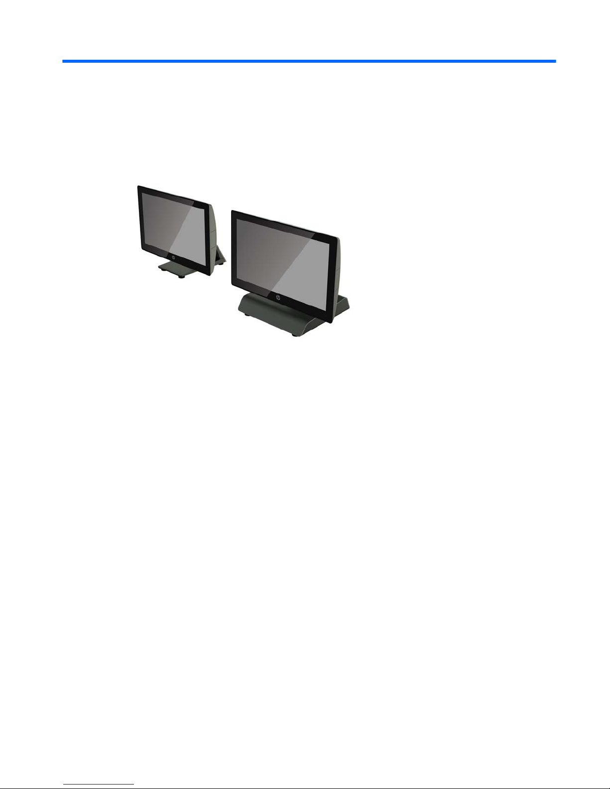
1 Product overview
Standard features
The HP RP9 G1 Retail System includes the following features.
●
Integrated All-in-One (AiO) form factor
●
Designed for long-term deployment within general retail, hospitality, and other markets
●
15.6” (Model 9015) and 18.5” (Model 9018) base models with Projected Capacitive touch technology
and 1366 x 768 resolution
●
VESA mounting holes (100 mm x 100 mm)
●
Choice of ergonomic stand, compact stand, or no stand (Display Head unit only)
●
Optional Integrated HP peripherals:
◦
Integrated magnetic strip reader (left mount or right mount options, encryption capable)
◦
2 x 20 LCD customer facing display (rear top mount or bottom mount with extension arm)
◦
7" LCD customer facing display (rear top mount or bottom mount with extension arm)
◦
Two integrated barcode scanners (one with left mount or right mount options, and one bottom
mount only)
◦
Integrated webcam (top mount only)
◦
Integrated biometric ngerprint reader (left mount or right mount options)
●
DDR4 2133 MHz Memory, up to 32GB maximum RAM
●
Operating system choices:
◦
Embedded 8.1 Industry ProRetail 64-bit
◦
FreeDos 2.0
◦
POSReady 7 32-bit
Standard features 1
Page 8

◦
POSReady 7 64-bit
◦
Windows 10 IoT Enterprise for Retail 64-bit
◦
Windows 10 Pro 64-bit
◦
Windows 10 Pro downgrade to Windows 7 Pro 32-bit
◦
Windows 10 Pro downgrade to Windows 7 Pro 64-bit
◦
Windows 10 Pro downgrade to Windows 8.1 Pro 64-bit
◦
Windows 7 Professional Edition 32-bit
◦
Windows 7 Professional Edition 64-bit
◦
Windows 8.1 Pro 64-bit
●
One M.2 slot for optional WLAN
●
Two USB 2.0 ports and two USB 3.0 ports
●
One 24V powered USB port and three 12V powered USB ports, two powered serial ports, and one cash
drawer port
●
Audio line-in and line-out ports
●
One DisplayPort for secondary display
●
One 2.5” internal storage bay for SATA HDD or SSD
●
Two M.2 internal storage bays
●
Cable management features
●
ENERGY STAR compliant
2 Chapter 1 Product overview
Page 9

Unfolding the ergonomic stand
If your model includes an ergonomic stand, the system is shipped with the stand in the folded position. Follow
the steps below to unfold the stand.
1. Unfold the stand to the desired position.
2. Route the DC power cord through the cable retainer and connect the cord to the rear I/O power
connector.
Unfolding the ergonomic stand 3
Page 10
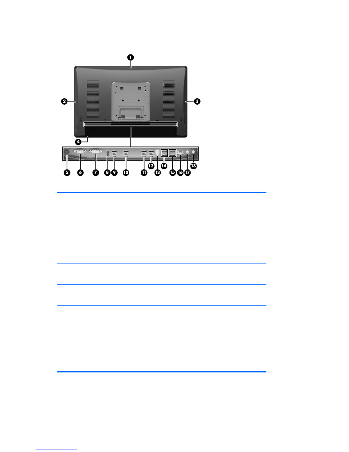
Rear components
1 Top USB port for optional HP integrated USB
webcam, 7” CFD, or 2 x 20 CFD (behind rear cover)
10 Powered USB 12V (B) used if the optional
bottom mount barcode scanner is installed
2 Side USB port for optional HP integrated USB
barcode scanner, MSR, or biometric reader
(behind rear cover)
11 Powered USB 12V (C)
3 Side USB port for optional HP integrated USB
barcode scanner, MSR, or biometric reader
(behind rear cover)
12 Powered USB 24V
4 Power button 13 Cash drawer connector
5 DC In power connector 14 USB 2.0 ports
6 Powered serial port (COM A) 15 USB 3.0 ports
7 Powered serial port (COM B) 16 RJ-45 network connector
8 DisplayPort (for secondary display) 17 Audio line in connector
9 Powered USB 12V (A) 18 Audio line out connector
NOTE: The powered serial ports can be congured for 0V, 5V, or 12V.
NOTE: The 24-volt Powered USB connector and the 12-volt Powered USB connector are keyed dierently as
a precaution to prevent connection errors.
NOTE: The cash drawer connector is covered by a sticker that must be removed to connect the cash drawer
cable.
CAUTION: The cash drawer connector is similar in size and shape to a modem jack. To avoid damage to the
computer, DO NOT plug a network cable into the cash drawer connector.
4 Chapter 1 Product overview
Page 11

2 Hardware upgrades
Tools needed
A Torx or at blade screwdriver can be used for procedures described in this guide.
Warnings and cautions
Before performing upgrades be sure to carefully read all of the applicable instructions, cautions, and
warnings in this guide.
WARNING! To reduce the risk of personal injury from electrical shock, hot surfaces, or re:
Disconnect the power cord from the wall outlet and allow the internal system components to cool before
touching.
Do not plug telecommunications or telephone connectors into the network interface controller (NIC)
receptacles.
Do not disable the power cord grounding plug. The grounding plug is an important safety feature.
Plug the power cord in a grounded (earthed) outlet that is easily accessible at all times.
To reduce the risk of serious injury, read the Safety & Comfort Guide. It describes proper workstation, setup,
posture, and health and work habits for computer users, and provides important electrical and mechanical
safety information. This guide is located on the Web at
http://www.hp.com/ergo.
WARNING! Energized and moving parts inside.
Disconnect power to the equipment before removing the enclosure.
Replace and secure the enclosure before turning power back on to the device.
CAUTION: Static electricity can damage the electrical components of the computer or optional equipment.
Before beginning these procedures, ensure that you are discharged of static electricity by briey touching a
grounded metal object. See Electrostatic discharge on page 43 for more information.
When the computer is plugged into an AC power source, voltage is always applied to the system board. You
must disconnect the power cord from the power source and wait approximately 30 seconds before opening
the computer to prevent damage to internal components.
Tools needed 5
Page 12
Removing and attaching the ergonomic and compact stands
The RP9 can be attached to a wall, swing arm, pole-mounted bracket, or other mounting xture by removing
the stand (when ordered attached to the system unit). The RP9 supports the VESA industry standard 100 mm
spacing between mounting holes.
This apparatus is intended to be supported by UL or CSA Listed wall mount bracket. HP recommends that you
use an HP Quick Release mounting bracket for wall mounting (part number EM870AA).
CAUTION: To attach a third-party mounting solution to the RP9, four 4 mm, 0.7 pitch, and 10 mm long
screws are required. Longer screws must not be used because they may damage the system. It is important to
verify that the manufacturer’s mounting solution is compliant with the VESA standard and is rated to support
the weight of the system.
Follow the steps below to remove the stand, mount the RP9 to a wall mount or swing arm, and to install the
stand.
1. Shut down the computer properly through the operating system, then turn o any external devices.
2. Disconnect the power cord from the power outlet.
CAUTION: Regardless of the power-on state, voltage is always present on the system board as long as
the system is plugged into an active AC outlet. You must disconnect the power cord and wait
approximately 30 seconds for the power to drain to avoid damage to the internal components of the
computer.
3. Disconnect all cables from the rear I/O connectors.
4. To remove the ergonomic stand, lay the RP9 face down on a at surface covered by a soft clean cloth.
Push up the release latch on the rear of the display head (1), tilt the stand back (2), and then lift up from
the display (3).
6 Chapter 2 Hardware upgrades
Page 13
5. To remove the compact stand, lay the RP9 face down on a at surface covered by a soft clean cloth. Push
up the release latch on the rear of the display head (1), tilt the stand back (2), and then lift up from the
display (3).
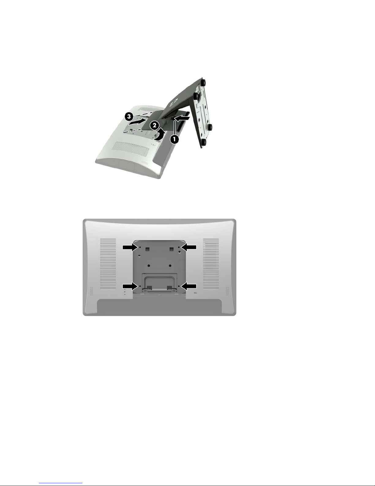
6. To mount the display head to a wall or swing arm, use the 100 mm x 100 mm VESA mounting holes on
the rear of the display head.
Removing and attaching the ergonomic and compact stands 7
Page 14
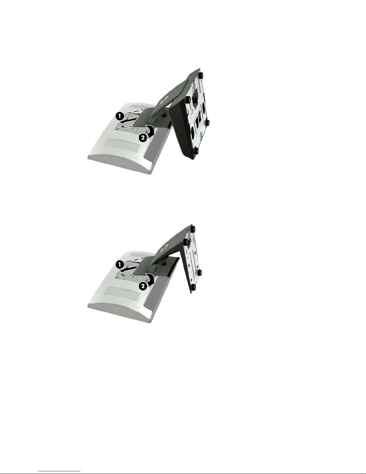
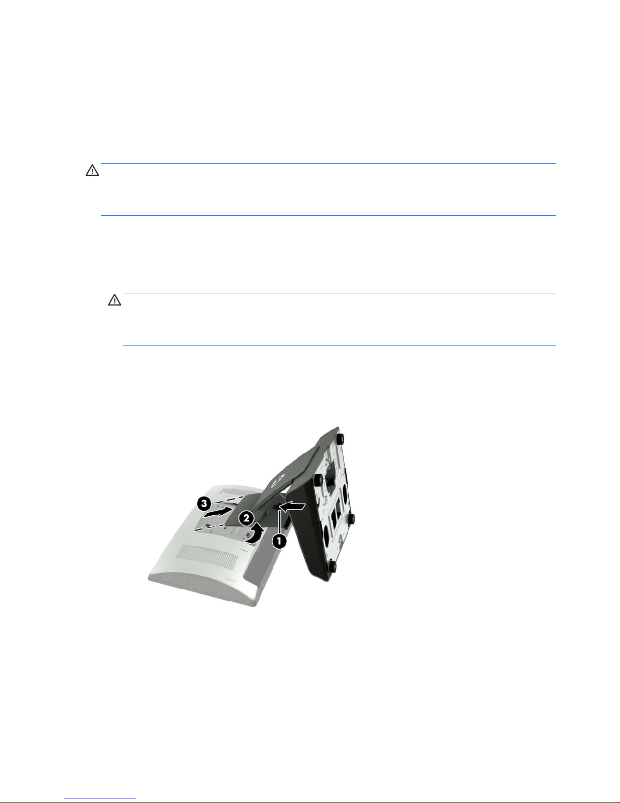
7. To attach the ergonomic stand, lay the RP9 face down on a at surface covered by a soft clean cloth.
Slide the tabs on the top of the stand mount into the slots on the display head (1), and then rotate the
bottom of the stand mount down onto the display head so that it snaps in place (2).
8. To attach the compact stand, lay the RP9 face down on a at surface covered by a soft clean cloth. Slide
the tabs on the top of the stand mount into the slots on the display head (1), and then rotate the bottom
of the stand mount down onto the display head so that it snaps in place (2).
8 Chapter 2 Hardware upgrades
Page 15
Routing cables (ergonomic stand)
1. Shut down the computer properly through the operating system, then turn o any external devices.
2. Disconnect the power cord from the power outlet.
CAUTION: Regardless of the power-on state, voltage is always present on the system board as long as
the system is plugged into an active AC outlet. You must disconnect the power cord and wait
approximately 30 seconds for the power to drain to avoid damage to the internal components of the
computer.
3. Connect the cables to the appropriate rear connectors.
NOTE: Tilt the display head back for easy access to the rear connectors.
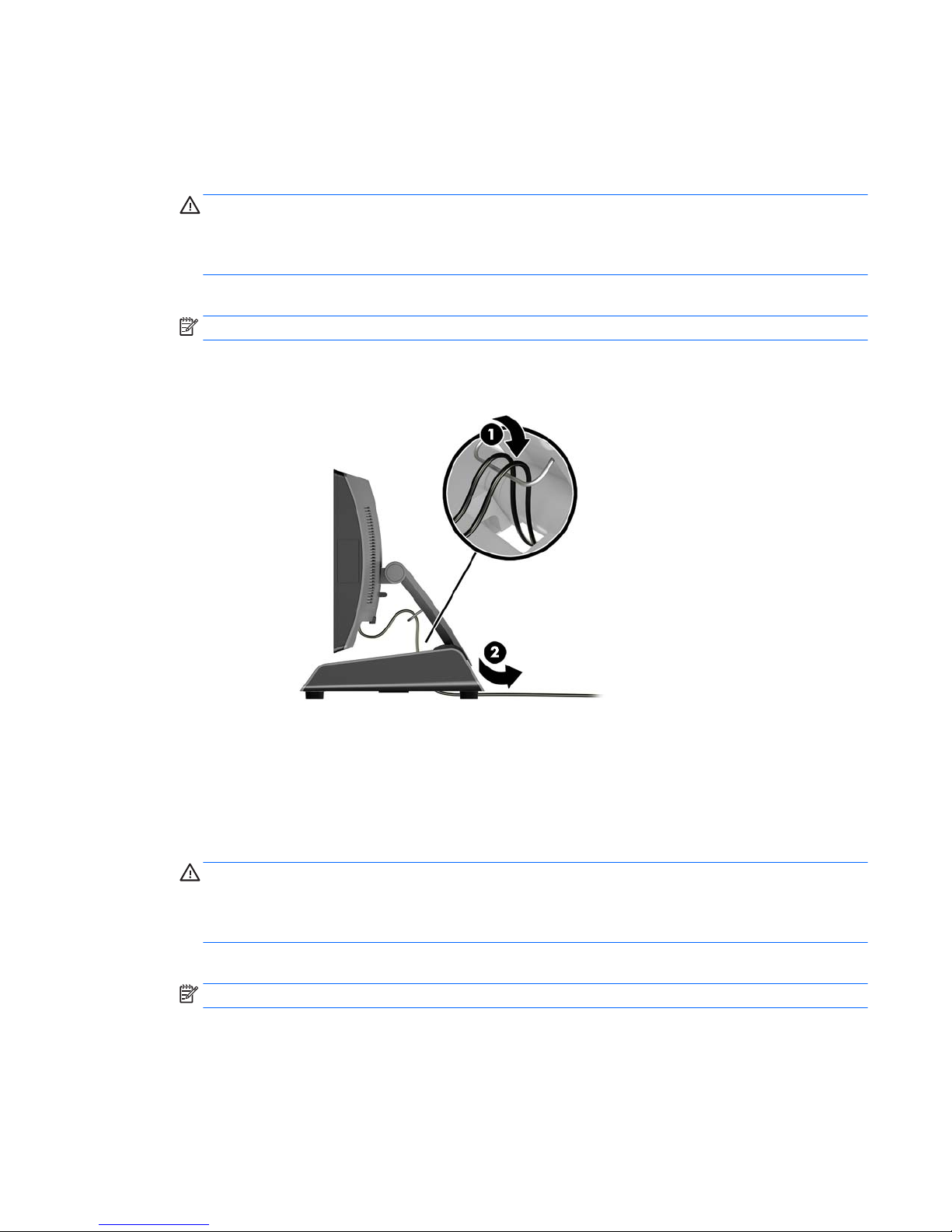
4. Route the cables from the connectors on the rear panel through the cable retainer on the neck of the
stand (1), and then through the hole in the center of the base and out the underside of the base (2).
5. Reconnect the power cord and press the power button.
Routing cables (compact stand)
1. Shut down the computer properly through the operating system, then turn o any external devices.
2. Disconnect the power cord from the power outlet.
CAUTION: Regardless of the power-on state, voltage is always present on the system board as long as
the system is plugged into an active AC outlet. You must disconnect the power cord and wait
approximately 30 seconds for the power to drain to avoid damage to the internal components of the
computer.
3. Connect the cables to the appropriate rear connectors.
NOTE: Tilt the display head back for easy access to the rear connectors.
4. Snap o the cable routing cover on the neck of the stand (1).
5. Route the cables from the connectors on the rear panel down the neck of the stand, and then through
the hole in the center of the base and out the underside of the base (2).
Routing cables (ergonomic stand) 9
Page 16
6. Snap the cable routing cover onto the neck of the stand to cover the cables (3).
7. Reconnect the power cord and press the power button.
Removing and replacing the power supply (ergonomic stand)
1. Shut down the computer properly through the operating system, then turn o any external devices.
2. Disconnect the power cord from the power outlet.
CAUTION: Regardless of the power-on state, voltage is always present on the system board as long as
the system is plugged into an active AC outlet. You must disconnect the power cord and wait
approximately 30 seconds for the power to drain to avoid damage to the internal components of the
computer.
3. Unplug the DC power cable from the connector on the rear of the display head.
4. Pull up on the center of the cover on the right side of the base and rotate the cover upward.
10 Chapter 2 Hardware upgrades
Page 17

5. Pull up on the center of the cover on the left side of the base and rotate the cover upward.
6. Lay the RP9 face down on a at surface covered by a soft clean cloth. Lift the pull tab and loosen the
screw on the bottom plate of the stand (1), then lift the bottom of the plate up (2), and then pull the
plate o the stand (3).
Removing and replacing the power supply (ergonomic stand) 11
Page 18

7. Unplug the AC power cord from the side of the power supply (1), and then lift the power supply out of
the stand’s base (2).
8. Route the xed side of the new power supply’s power cord through the hole in the center of the base and
connect it to the DC power connector on the rear panel (1). Place the new power supply into the stand’s
base (2), and then connect the AC power cord to the side of the power supply (3) and route the cord
through the retainer slot on the base.
12 Chapter 2 Hardware upgrades
Page 19

9. Slide the tabs on the base plate into the slots on the base (1), rotate the plate onto the base (2) , and
then tighten the base plate screw (3).
10. Snap the right side cover back onto the stand’s base.
Removing and replacing the power supply (ergonomic stand) 13
Page 20

11. Snap the left side cover back onto the stand’s base.
12. Connect the power cord to an electrical outlet.
Installing an optional HP integrated USB barcode scanner,
magnetic strip reader (MSR), biometric reader, or webcam
Only install HP approved integrated USB modules designed for these USB ports. The USB ports do not support
optical drives or hard drives.
The integrated barcode scanner, integrated MSR, and integrated biometric reader can be installed on the left
or right side of the display head. The integrated webcam can only be installed on the top of the display head.
There is a separate integrated barcode scanner that can be installed on the bottom of the display head.
Installing an optional HP integrated USB module on the sides or top of the display
head
The procedure for installing a module is the same for all modules, whether it is on the left side, the right side,
or the top of the display head.
1. Shut down the computer properly through the operating system, then turn o any external devices.
2. Disconnect the power cord from the power outlet.
CAUTION: Regardless of the power-on state, voltage is always present on the system board as long as
the system is plugged into an active AC outlet. You must disconnect the power cord and wait
approximately 30 seconds for the power to drain to avoid damage to the internal components of the
computer.
3. Disconnect all cables from the rear I/O connectors.
14 Chapter 2 Hardware upgrades
Page 21

4. Press the two rear cover latches outward (1). Slide the rear cover up, and then lift it o the display head
(2).
5. Remove the two screws that secure the port cover (1), and then pull the port cover o the display head
(2).
NOTE: You may need to gently loosen the port cover from inside of the screw holes with a at
screwdriver.
Installing an optional HP integrated USB barcode scanner, magnetic strip reader (MSR), biometric reader,
or webcam
15
Page 22

6. Insert the USB connector on the module into the USB port (1), and then secure the module with the two
screws that were previously removed (2).
7. Align the tabs on the rear cover with the slots on the display head while placing the cover on the display
head, and then slide the cover down so that it snaps in place.
8. Reconnect all cables to the rear I/O connectors.
9. Reconnect the power cord and press the power button.
16 Chapter 2 Hardware upgrades
Page 23

Installing an optional HP integrated USB barcode scanner on the bottom of the
display head
1. Shut down the computer properly through the operating system, then turn o any external devices.
2. Disconnect the power cord from the power outlet.
CAUTION: Regardless of the power-on state, voltage is always present on the system board as long as
the system is plugged into an active AC outlet. You must disconnect the power cord and wait
approximately 30 seconds for the power to drain to avoid damage to the internal components of the
computer.
3. Disconnect all cables from the rear I/O connectors.
4. Slide the cover on the barcode scanner down and then lift the cover up to remove it (1). Plug the barcode
scanner into the rear I/O Powered USB 12V (B) connector (2), and then secure the barcode scanner with
the screw provided (3). Replace the barcode scanner cover (4).
5. Reconnect all cables to the rear I/O connectors.
6. Reconnect the power cord and press the power button.
Installing an optional HP integrated USB barcode scanner, magnetic strip reader (MSR), biometric reader,
or webcam
17
Page 24

Installing a 2 x 20 LCD or 7” LCD customer facing display (CFD)
A short extension arm CFD can be attached to the top of the display head or a long extension arm CFD can be
attached to the bottom of the stand’s base. The procedure for installing a CFD is the same, whether it is a 2 x
20 or 7” LCD.
Installing a top mount CFD
1. Shut down the computer properly through the operating system, then turn o any external devices.
2. Disconnect the power cord from the power outlet.
CAUTION: Regardless of the power-on state, voltage is always present on the system board as long as
the system is plugged into an active AC outlet. You must disconnect the power cord and wait
approximately 30 seconds for the power to drain to avoid damage to the internal components of the
computer.
3. Disconnect all cables from the rear I/O connectors.
4. Press the two rear cover latches outward (1). Slide the rear cover up, and then lift it o the display head
(2).
18 Chapter 2 Hardware upgrades
Page 25

5. Remove the two screws that secure the top port cover (1), and then pull the port cover o the display
head (2).
NOTE: You may need to gently loosen the port cover from inside of the screw holes with a at
screwdriver.
6. Align the tabs on the rear cover with the slots on the display head while placing the cover on the display
head, and then slide the cover down so that it snaps in place.
Installing a 2 x 20 LCD or 7” LCD customer facing display (CFD) 19
Page 26

7. Remove the cover from the CFD arm by pulling back the top of the cover (1) and then the bottom of the
cover. Insert the USB connector on the CFD into the USB port (2), and then secure the CFD with the screw
provided (3). Replace the arm cover (4) by snapping on the top of the cover and then the bottom of the
cover.
8. Reconnect all cables to the rear I/O connectors.
9. Reconnect the power cord and press the power button.
Installing a bottom mount CFD
1. Shut down the computer properly through the operating system, then turn o any external devices.
2. Disconnect the power cord from the power outlet.
CAUTION: Regardless of the power-on state, voltage is always present on the system board as long as
the system is plugged into an active AC outlet. You must disconnect the power cord and wait
approximately 30 seconds for the power to drain to avoid damage to the internal components of the
computer.
3. Unplug the power cable from the connector on the rear of the display head.
4. Lay the RP9 face down on a at surface covered by a soft clean cloth.
20 Chapter 2 Hardware upgrades
Page 27

5. Slide the CFD bracket onto the underside of the base (1), and then secure the bracket with the screw (2).
6. Route the CFD cable up through the center hole in the base and connect it to a USB port on the rear I/O.
7. Reconnect the power cord and press the power button.
Installing a 2 x 20 LCD or 7” LCD customer facing display (CFD) 21
Page 28

Installing memory
The computer comes with at least one preinstalled double data rate 4 synchronous dynamic random access
memory (DDR4-SDRAM) small outline dual inline memory module (SODIMM). There are two memory sockets
on the system board that can be populated with up to 32GB of memory.
DDR4-SDRAM SODIMMs
For proper system operation, the SODIMMs must be:
●
industry-standard 260-pin
●
unbuered non-ECC PC4-17000 DDR4-2133 MHz-compliant
●
1.2 volt DDR4-SDRAM SODIMMs
The SODIMMs must also:
●
support CAS latency 15 DDR4 2133 MHz (15-15-15 timing)
●
contain the mandatory Joint Electronic Device Engineering Council (JEDEC) specication
In addition, the computer supports:
●
512-Mbit, 1-Gbit, 2-Gbit, 4-Gbit, and 8-Gbit non-ECC memory technologies
●
single-sided and double-sided SODIMMs
●
The following SODIMMs are oered:
◦
4GB DDR4-2133 SODIMM (1 x 4GB) RAM
◦
8GB DDR4-2133 SODIMM (2 x 4GB) RAM
◦
8GB DDR4-2133 SODIMM (1 x 8GB) RAM
◦
16GB DDR4-2133 SODIMM (1 x 16GB) RAM
◦
16GB DDR4-2133 SODIMM (2 x 8GB) RAM
◦
32GB DDR4-2133 SODIMM (2 x 16GB) RAM
NOTE: The system will not operate properly if you install unsupported SODIMMs.
Removing and installing a SODIMM
CAUTION: You must disconnect the power cord and wait approximately 30 seconds for the power to drain
before replacing the memory module. Regardless of the power-on state, voltage is always supplied to the
memory module as long as the computer is plugged into an active AC outlet. Adding or removing the memory
module while voltage is present may cause irreparable damage to the memory module or system board.
The memory module socket has gold-plated metal contacts. When upgrading the memory, it is important to
use a memory module with gold-plated metal contacts to prevent corrosion and/or oxidation resulting from
having incompatible metals in contact with each other.
Static electricity can damage the electronic components of the computer or optional cards. Before beginning
these procedures, ensure that you are discharged of static electricity by briey touching a grounded metal
object. For more information, refer to
Electrostatic discharge on page 43.
When handling a memory module, be careful not to touch any of the contacts. Doing so may damage the
module.
22 Chapter 2 Hardware upgrades
Page 29

1. Shut down the computer properly through the operating system, then turn o any external devices.
2. Disconnect the power cord from the power outlet.
CAUTION: You must disconnect the power cord and wait approximately 30 seconds for the power to
drain before replacing the memory module. Regardless of the power-on state, voltage is always
supplied to the memory module as long as the computer is plugged into an active AC outlet. Adding or
removing a memory module while voltage is present may cause irreparable damage to the memory
module or system board.
3. Disconnect all cables from the rear I/O connectors.
4. Press the two rear cover latches outward (1). Slide the rear cover up, and then lift it o the display head
(2).
5. Use the nger slots on the rear metal shield to pull the top of the shield up, and then lift the shield o
the display head.
Installing memory 23
Page 30

6. To remove a SODIMM, press outward on the two latches on each side of the SODIMM (1), and then pull
the SODIMM out of the socket (2).
7. To install a SODIMM, slide the new SODIMM into the socket at approximately a 30° angle (1), and then
press the SODIMM down into the socket (2) so that the latches lock it in place.
NOTE: A memory module can be installed in only one way. Match the notch on the module with the tab
on the memory socket.
8. To replace the rear metal shield, slide the outer tabs on each side of the bottom of the shield under the
metal framework on the display head and the center tab on each side above the metal framework (1),
and then rotate the top of the shield onto the display head so that it snaps in place (2).
24 Chapter 2 Hardware upgrades
Page 31

9. Align the tabs on the rear cover with the slots on the display head while placing the cover on the display
head, and then slide the cover down so that it snaps in place.
10. Reconnect all cables to the rear I/O connectors.
11. Reconnect the power cord and press the power button.
The computer automatically recognizes the additional memory when you turn on the computer.
Installing memory 25
Page 32

Removing and installing a 2.5-inch hard drive
CAUTION: If you are replacing a hard drive, be sure to back up the data from the old drive so that you can
transfer the data to the new drive.
1. Shut down the computer properly through the operating system, then turn o any external devices.
2. Disconnect the power cord from the power outlet.
CAUTION: Regardless of the power-on state, voltage is always present on the system board as long as
the system is plugged into an active AC outlet. You must disconnect the power cord and wait
approximately 30 seconds for the power to drain to avoid damage to the internal components of the
computer.
3. Disconnect all cables from the rear I/O connectors.
4. Press the two rear cover latches outward (1). Slide the rear cover up, and then lift it o the display head
(2).
5. Use the nger slots on the rear metal shield to pull the top of the shield up, and then lift the shield o
the display head.
26 Chapter 2 Hardware upgrades
Page 33

6. Disconnect the cable from the rear of the drive (1), pull the arm back at the rear of the drive (2), and then
slide the drive back and lift it out of the drive bay (3).
7. If replacing the drive, remove the four mounting screws from the drive and install them in the new drive.
NOTE: If you need mounting screws for the drive, four extra mounting screws are installed on the drive
bay frame.
Removing and installing a 2.5-inch hard drive 27
Page 34

8. Place the drive down into the drive bay, slide the drive forward (1), and then connect the cable to the
rear of the drive (2).
9. To replace the rear metal shield, slide the outer tabs on each side of the bottom of the shield under the
metal framework on the display head and the center tab on each side above the metal framework (1),
and then rotate the top of the shield onto the display head so that it snaps in place (2).
28 Chapter 2 Hardware upgrades
Page 35

10. Align the tabs on the rear cover with the slots on the display head while placing the cover on the display
head, and then slide the cover down so that it snaps in place.
11. Reconnect all cables to the rear I/O connectors.
12. Reconnect the power cord and press the power button.
Removing and installing an M.2 storage device
There are two M.2 storage device connectors located under the 2.5” drive bay.
1. Shut down the computer properly through the operating system, then turn o any external devices.
2. Disconnect the power cord from the power outlet.
CAUTION: Regardless of the power-on state, voltage is always present on the system board as long as
the system is plugged into an active AC outlet. You must disconnect the power cord and wait
approximately 30 seconds for the power to drain to avoid damage to the internal components of the
computer.
3. Disconnect all cables from the rear I/O connectors.
Removing and installing an M.2 storage device 29
Page 36

4. Press the two rear cover latches outward (1). Slide the rear cover up, and then lift it o the display head
(2).
5. Use the nger slots on the rear metal shield to pull the top of the shield up, and then lift the shield o
the display head.
30 Chapter 2 Hardware upgrades
Page 37

6. Remove the 2.5” drive if one is installed. Disconnect the cable from the rear of the drive (1), pull the arm
back at the rear of the drive (2), and then slide the drive back and lift it out of the drive bay (3).
7. To remove an M.2 storage device, remove the screw that secures the device to the system board (1) so
that the end pops up (2), and then slide the device out of the connector (3).
NOTE: Due to the small size of the screw, a magnetized screwdriver may be helpful to remove the
screw.
Removing and installing an M.2 storage device 31
Page 38

8. To install an M.2 storage device, slide the pins on the storage device into the system board connector
while holding the device at approximately a 30° angle (1). Rotate the other end of the device down (2),
and then secure the device with the screw that was either previously removed or preinstalled in the
screw hole (3).
9. Replace the 2.5” drive if it was removed. Place the drive down into the drive bay, slide the drive forward
(1), and then connect the cable to the rear of the drive (2).
32 Chapter 2 Hardware upgrades
Page 39

10. To replace the rear metal shield, slide the outer tabs on each side of the bottom of the shield under the
metal framework on the display head and the center tab on each side above the metal framework (1),
and then rotate the top of the shield onto the display head so that it snaps in place (2).
11. Align the tabs on the rear cover with the slots on the display head while placing the cover on the display
head, and then slide the cover down so that it snaps in place.
12. Reconnect all cables to the rear I/O connectors.
13. Reconnect the power cord and press the power button.
Removing and installing an M.2 storage device 33
Page 40

Replacing the battery
The battery that comes with the computer provides power to the real-time clock. When replacing the battery,
use a battery equivalent to the battery originally installed in the computer. The computer comes with a 3-volt
lithium coin cell battery.
WARNING! The computer contains an internal lithium manganese dioxide battery. There is a risk of re and
burns if the battery is not handled properly. To reduce the risk of personal injury:
Do not attempt to recharge the battery.
Do not expose to temperatures higher than 60°C (140°F).
Do not disassemble, crush, puncture, short external contacts, or dispose of in re or water.
Replace the battery only with the HP spare designated for this product.
CAUTION: Before replacing the battery, it is important to back up the computer CMOS settings. When the
battery is removed or replaced, the CMOS settings will be cleared.
Static electricity can damage the electronic components of the computer or optional equipment. Before
beginning these procedures, ensure that you are discharged of static electricity by briey touching a
grounded metal object.
NOTE: The lifetime of the lithium battery can be extended by plugging the computer into a live AC wall
socket. The lithium battery is only used when the computer is NOT connected to AC power.
HP encourages customers to recycle used electronic hardware, HP original print cartridges, and rechargeable
batteries. For more information about recycling programs, go to http://www.hp.com/recycle.
1. Shut down the computer properly through the operating system, then turn o any external devices.
2. Disconnect the power cord from the power outlet.
CAUTION: Regardless of the power-on state, voltage is always present on the system board as long as
the system is plugged into an active AC outlet. You must disconnect the power cord and wait
approximately 30 seconds for the power to drain to avoid damage to the internal components of the
computer.
3. Disconnect all cables from the rear I/O connectors.
4. Press the two rear cover latches outward (1). Slide the rear cover up, and then lift it o the display head
(2).
34 Chapter 2 Hardware upgrades
Page 41

5. Use the nger slots on the rear metal shield to pull the top of the shield up, and then lift the shield o
the display head.
6. To release the battery from its holder, squeeze the metal clamp that extends above one edge of the
battery. When the battery pops up, lift it out (1).
7. To insert the new battery, slide one edge of the replacement battery under the lip of the holder with the
positive side up. Push the other edge down until the clamp snaps over the other edge of the battery (2).
Replacing the battery 35
Page 42

8. To replace the rear metal shield, slide the outer tabs on each side of the bottom of the shield under the
metal framework on the display head and the center tab on each side above the metal framework (1),
and then rotate the top of the shield onto the display head so that it snaps in place (2).
9. Align the tabs on the rear cover with the slots on the display head while placing the cover on the display
head, and then slide the cover down so that it snaps in place.
10. Reconnect all cables to the rear I/O connectors.
11. Reconnect the power cord and press the power button.
36 Chapter 2 Hardware upgrades
Page 43

Installing a port cover
The rear I/O port cover is available from HP. To install the port cover, snap the port cover onto the rear panel
over the ports (1) and secure it with the screw (2).
Securing the RP9 to a counter top
1. Shut down the computer properly through the operating system, then turn o any external devices.
2. Disconnect the power cord from the power outlet.
CAUTION: Regardless of the power-on state, voltage is always present on the system board as long as
the system is plugged into an active AC outlet. You must disconnect the power cord and wait
approximately 30 seconds for the power to drain to avoid damage to the internal components of the
computer.
3. If securing an ergonomic stand, there are two screw holes accessible through the center of the stand’s
base. Fasten the stand to the counter top using the appropriate fastening devices (not provided by HP)
for your surface.
Installing a port cover 37
Page 44

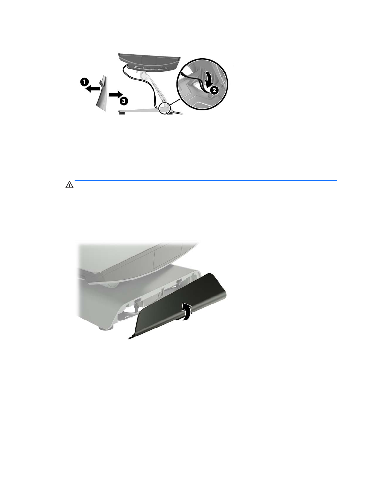
4. If securing a compact stand, snap the cover o the neck of the stand (1), and then slide the base cover
forward and lift it o the base (2).
5. Fasten the compact stand to the counter top using the appropriate fastening devices (not provided by
HP) for your surface.
38 Chapter 2 Hardware upgrades
Page 45

6. Slide the base cover back onto the base of the compact stand (1), and then snap the neck cover onto the
neck of the stand (2).
7. Reconnect the power cord and press the power button.
Installing an external security lock
Cable lock
A cable lock can be used to secure the RP9 to an external object.
Installing an external security lock 39
Page 46

Padlock
A padlock can be used to secure the RP9 to an external object.
1. Install the padlock security loop on the rear panel. Place the base of the loop into the slots on the rear
panel (1), and then secure the loop to the rear panel with the screw (2).
NOTE: The padlock security loop and screw are provided with the RP9.
2. Connect a cable that is attached to an external object to the padlock and insert the padlock into the
security loop.
40 Chapter 2 Hardware upgrades
Page 47

3 Conguring the software
Touch screen calibration
HP recommends that you calibrate the touch screen before using the system to ensure that the touch point
registers on the screen where the stylus or nger touches the screen. If at any time you nd that the touch
point is not registering properly, you may need to repeat the calibration process.
Calibration for Windows 7 Professional and Embedded POSReady 7
To calibrate the touch module in Windows 7 Professional and Embedded POSReady 7:
1. Open the Start menu, tap the Control Panel link and type “calibrate” in the Search box. Under Tablet PC
Settings, tap the Calibrate the screen for pen or touch input link. In the Tablet PC Settings dialog box,
tap the Calibrate button, then proceed to step 2.
2. Follow the on-screen instructions to press the target marks on the touch screen. At the end of the
calibration process, the touch module should be aligned with the video and the touch points will be
accurate.
Calibration for Windows 8.1 Professional and Embedded 8.1 Industry Pro Retail
To calibrate the touch module in Windows 8.1 Professional and Embedded 8.1 Industry Pro Retail:
1. Launch the Control Panel. You can type “Control Panel” in the Search box to access it.
2. In the Control Panel type “calibrate” in the Search box. Under Tablet PC Settings, tap the Calibrate the
screen for pen or touch input link. In the Tablet PC Settings dialog box, tap the Calibrate button, then
proceed to step 3.
3. Follow the on-screen instructions to press the target marks on the touch screen. At the end of the
calibration process, the touch module should be aligned with the video and the touch points will be
accurate.
Calibration for Windows 10 Professional and Windows 10 IoT Enterprise for Retail
To calibrate the touch module in Windows 10 Professional and Windows 10 IoT Enterprise for Retail:
1. Launch the Control Panel. You can type “Control Panel” in the Search box to access it.
2. In the Control Panel type “calibrate” in the Search box. Under Tablet PC Settings, tap the Calibrate the
screen for pen or touch input link. In the Tablet PC Settings dialog box, tap the Calibrate button, then
proceed to step 3.
3. Follow the on-screen instructions to press the target marks on the touch screen. At the end of the
calibration process, the touch module should be aligned with the video and the touch points will be
accurate.
Touch screen calibration 41
Page 48

Conguring all optional HP integrated USB peripheral modules
(HP integrated USB barcode scanner, magnetic strip reader
(MSR), biometric reader, or webcam)
To congure the integrated USB peripheral, refer to the HP Point of Sale Conguration Guide (available in
English only). The guide is located with the documentation on your retail computer and at
http://www.hp.com/support. To access the guide on the retail computer, select Start > HP Point of Sale
Information.
NOTE: Check http://www.hp.com/support for updated software or documentation that became available
between the time your product was manufactured and the time it was delivered to you.
Conguring powered serial ports
The serial ports can be congured as standard (non-powered) serial ports or powered serial ports. Some
devices use a powered serial port. If the serial port is congured as a powered port, devices that support a
powered serial interface do not require an external power source.
CAUTION: The system must be powered o before connecting or disconnecting serial port devices.
NOTE: The computer ships with all serial ports congured in standard non-powered serial mode (0 Volts) by
default.
The serial ports can be congured using the Computer F10 Setup utility. Under the Onboard Devices menu,
you are given the option to select the following three settings for each individual serial port.
●
0 Volts
●
5 Volts
●
12 Volts
CAUTION: Unplug all devices currently connected to the powered serial ports and reboot the computer
before changing the serial port voltage settings in the Computer F10 Setup utility.
NOTE: To access the Computer F10 Setup utility, restart the computer and press the F10 key as soon as the
HP logo screen is displayed (before the computer boots to the operating system).
42 Chapter 3 Conguring the software
Page 49

A Electrostatic discharge
A discharge of static electricity from a nger or other conductor may damage system boards or other staticsensitive devices. This type of damage may reduce the life expectancy of the device.
Preventing electrostatic damage
To prevent electrostatic damage, observe the following precautions:
●
Avoid hand contact by transporting and storing products in static-safe containers.
●
Keep electrostatic-sensitive parts in their containers until they arrive at static-free workstations.
●
Place parts on a grounded surface before removing them from their containers.
●
Avoid touching pins, leads, or circuitry.
●
Always be properly grounded when touching a static-sensitive component or assembly.
Grounding methods
There are several methods for grounding. Use one or more of the following methods when handling or
installing electrostatic-sensitive parts:
●
Use a wrist strap connected by a ground cord to a grounded workstation or computer chassis. Wrist
straps are exible straps with a minimum of 1 megohm +/- 10 percent resistance in the ground cords. To
provide proper ground, wear the strap snug against the skin.
●
Use heelstraps, toestraps, or bootstraps at standing workstations. Wear the straps on both feet when
standing on conductive oors or dissipating oor mats.
●
Use conductive eld service tools.
●
Use a portable eld service kit with a folding static-dissipating work mat.
If you do not have any of the suggested equipment for proper grounding, contact an HP authorized dealer,
reseller, or service provider.
NOTE: For more information on static electricity, contact an HP authorized dealer, reseller, or service
provider.
Preventing electrostatic damage 43
Page 50

B Computer operating guidelines, routine
care and shipping preparation
Computer operating guidelines and routine care
Follow the guidelines below to properly set up and care for the computer:
●
HP recommends a 17 mm clearance from the ns on the rear panel for heat dissipation.
●
Keep the HP RP9 Retail System away from excessive moisture, direct sunlight, and extremes of heat and
cold.
●
Never operate the computer with any access panels removed.
●
Do not stack computers on top of each other or place computers so near each other that they are subject
to each other’s re-circulated or preheated air.
●
If the computer is to be operated within a separate enclosure, intake and exhaust ventilation must be
provided on the enclosure, and the same operating guidelines listed above will still apply.
●
Keep liquids away from the RP9 Retail System.
●
Never cover the ns on the rear panel of the computer with any type of material.
●
Install or enable power management functions of the operating system or other software, including
sleep states.
●
Shut down the computer before you do either of the following:
◦
Wipe the exterior of the computer with a soft, damp cloth as needed. Using cleaning products may
discolor or damage the nish.
◦
Occasionally clean the ns on the rear panel to keep them free of lint, dust, and other foreign
matter that may inhibit heat dissipation from the ns.
NOTE: For more information on your retail system care and maintenance, refer to “Retail Point of Sales
Systems - Routine Care and Maintenance” available at http://www.hp.com/support.
Touch screen maintenance
Keep your display and touch sensor clean. The touch sensor requires very little maintenance. HP recommends
that you periodically clean the glass touch sensor surface. Be sure to turn o your display before cleaning.
Typically, an isopropyl alcohol and water solution ratio of 50:50 is the best cleaning agent for your touch
sensor. It is important to avoid using any caustic chemicals on the touch sensor. Do not use any vinegarbased solutions.
Apply the cleaner with a soft, lint-free cloth. Avoid using gritty cloths. Always dampen the cloth and then
clean the sensor. Be sure to spray the cleaning liquid onto the cloth, not the sensor, so that drips do not seep
inside the display or stain the bezel.
44 Appendix B Computer operating guidelines, routine care and shipping preparation
Page 51

Shipping preparation
Follow these suggestions when preparing to ship the computer:
1. Back up the hard drive les. Be sure that the backup media is not exposed to electrical or magnetic
impulses while stored or in transit.
NOTE: The hard drive locks automatically when the system power is turned o.
2. Remove and store all removable media.
3. Turn o the computer and external devices.
4. Disconnect the power cord from the electrical outlet, then from the computer.
5. Disconnect the system components and external devices from their power sources, then from the
computer.
6. Pack the system components and external devices in their original packing boxes or similar packaging
with suicient packing material to protect them.
Shipping preparation 45
Page 52

Index
B
barcode scanner
installation 14
battery
removing and installing 34
biometric reader
installation 14
C
compact stand
removing and replacing 6
routing cables 9
securing to counter top 37
computer operating guidelines 44
customer facing display (CFD)
installation 18
E
electrostatic discharge, preventing
damage 43
ergonomic stand
power supply removal and
replacement 10
removing and replacing 6
routing cables 9
securing to counter top 37
unfolding 3
F
features 1
H
hard drive
removing and installing 26
I
installation guidelines 5
integrated USB peripherals
conguring 42
installing 14, 18
M
M.2 storage device
removing and installing 29
magnetic strip reader (MSR)
installation 14
memory
removing and installing 22
specications 22
P
port cover 37
R
rear components 4
S
security locks 39
serial ports, conguring for power
42
shipping preparation 45
T
touch screen
calibration 41
maintenance 44
V
ventilation guidelines 44
W
wall mount 6
webcam
installation 14
46 Index
 Loading...