

Page 1

User Guide
hp rp7405/7410 Servers
Third Edition
Manufacturing Part Number: A6752-96008
21102
USA
© Copyright 2002
Page 2

Legal Notices
The information in this document is subject to change without notice.
Hewlett-Packard makes no warranty of any kind with regard to this manual, including, but not limited to, the
implied warranties of merchantability and fitness for a particular purpose. Hewlett-Packard shall not be held
liable for errors contained herein or direct, indirect, special, incidental or consequential damages in
connection with the furnishing, performance, or use of this material.
Restricted Rights Legend. Use, duplication or disclosure by the U.S. Government is subject to restrictions
as set forth in subparagraph (c) (1) (ii) of the Rights in Technical Data and Computer Software clause at
DFARS 252.227-7013 for DOD agencies, and subparagraphs (c) (1) and (c) (2) of the Commercial Computer
Software Restricted Rights clause at FAR 52.227-19 for other agencies.
HEWLETT-PACKARD COMPANY 3000 Hanover Street Palo Alto, California 94304 U.S.A.
Copyright Notices. ©copyright 1983-2002 Hewlett-Packard Company, all rights reserved.
Reproduction, adaptation, or translation of this document without prior written permission is prohibited,
except as allowed under the copyright laws.
ii
Page 3

1. Introduction
hp rp7405/rp7410 Overview . . . . . . . . . . . . . . . . . . . . . . . . . . . . . . . . . . . . . . . . . . . . . . . . . . . . . . . . . . . . 2
Cell Board . . . . . . . . . . . . . . . . . . . . . . . . . . . . . . . . . . . . . . . . . . . . . . . . . . . . . . . . . . . . . . . . . . . . . . . . . 3
System Backplane. . . . . . . . . . . . . . . . . . . . . . . . . . . . . . . . . . . . . . . . . . . . . . . . . . . . . . . . . . . . . . . . . . . 4
I/O Subsystem . . . . . . . . . . . . . . . . . . . . . . . . . . . . . . . . . . . . . . . . . . . . . . . . . . . . . . . . . . . . . . . . . . . . . . 4
hp rp7405 Servers . . . . . . . . . . . . . . . . . . . . . . . . . . . . . . . . . . . . . . . . . . . . . . . . . . . . . . . . . . . . . . . . . . . . 5
Detailed hp rp7405/rp7410 Description . . . . . . . . . . . . . . . . . . . . . . . . . . . . . . . . . . . . . . . . . . . . . . . . . . . 6
Cell Board . . . . . . . . . . . . . . . . . . . . . . . . . . . . . . . . . . . . . . . . . . . . . . . . . . . . . . . . . . . . . . . . . . . . . . . . . 7
Cells and nPartitions . . . . . . . . . . . . . . . . . . . . . . . . . . . . . . . . . . . . . . . . . . . . . . . . . . . . . . . . . . . . . . . . 9
System Backplane. . . . . . . . . . . . . . . . . . . . . . . . . . . . . . . . . . . . . . . . . . . . . . . . . . . . . . . . . . . . . . . . . . 11
I/O Subsystem . . . . . . . . . . . . . . . . . . . . . . . . . . . . . . . . . . . . . . . . . . . . . . . . . . . . . . . . . . . . . . . . . . . . . 11
Package Description . . . . . . . . . . . . . . . . . . . . . . . . . . . . . . . . . . . . . . . . . . . . . . . . . . . . . . . . . . . . . . . . 14
2. Installation
Unpacking the Server . . . . . . . . . . . . . . . . . . . . . . . . . . . . . . . . . . . . . . . . . . . . . . . . . . . . . . . . . . . . . . . . 18
Unpacking a Racked Server . . . . . . . . . . . . . . . . . . . . . . . . . . . . . . . . . . . . . . . . . . . . . . . . . . . . . . . . . . 18
Unpacking a Non-Racked Server. . . . . . . . . . . . . . . . . . . . . . . . . . . . . . . . . . . . . . . . . . . . . . . . . . . . . . 22
Installing Server Into the Rack . . . . . . . . . . . . . . . . . . . . . . . . . . . . . . . . . . . . . . . . . . . . . . . . . . . . . . . 28
Installing the Cable Management Arm (CMA) . . . . . . . . . . . . . . . . . . . . . . . . . . . . . . . . . . . . . . . . . . . 29
Installing Add-On Products . . . . . . . . . . . . . . . . . . . . . . . . . . . . . . . . . . . . . . . . . . . . . . . . . . . . . . . . . . 30
Connecting AC Input Power . . . . . . . . . . . . . . . . . . . . . . . . . . . . . . . . . . . . . . . . . . . . . . . . . . . . . . . . . . . 34
MP Core I/O Connections . . . . . . . . . . . . . . . . . . . . . . . . . . . . . . . . . . . . . . . . . . . . . . . . . . . . . . . . . . . . . 36
MP/SCSI Connections. . . . . . . . . . . . . . . . . . . . . . . . . . . . . . . . . . . . . . . . . . . . . . . . . . . . . . . . . . . . . . . 36
LAN/SCSI Connections . . . . . . . . . . . . . . . . . . . . . . . . . . . . . . . . . . . . . . . . . . . . . . . . . . . . . . . . . . . . . 36
Management Processor Access. . . . . . . . . . . . . . . . . . . . . . . . . . . . . . . . . . . . . . . . . . . . . . . . . . . . . . . . 36
Setting Up the CE Tool (PC) . . . . . . . . . . . . . . . . . . . . . . . . . . . . . . . . . . . . . . . . . . . . . . . . . . . . . . . . . 37
Standby Power and Logging in to the MP. . . . . . . . . . . . . . . . . . . . . . . . . . . . . . . . . . . . . . . . . . . . . . . 38
Configuring LAN Information for the MP. . . . . . . . . . . . . . . . . . . . . . . . . . . . . . . . . . . . . . . . . . . . . . . 40
Verifying Presence of the Cell Boards . . . . . . . . . . . . . . . . . . . . . . . . . . . . . . . . . . . . . . . . . . . . . . . . . . 42
Powering On the hp rp7405/rp7410 Server . . . . . . . . . . . . . . . . . . . . . . . . . . . . . . . . . . . . . . . . . . . . . . . 44
Selecting a Boot Partition using the Management Processor . . . . . . . . . . . . . . . . . . . . . . . . . . . . . . . . 45
Verifying the System Configuration using Boot Console Handler (BCH) . . . . . . . . . . . . . . . . . . . . . . . 46
Booting HP-UX using Boot Console Handler (BCH) . . . . . . . . . . . . . . . . . . . . . . . . . . . . . . . . . . . . . . . . 47
Contents
3. Troubleshooting
Common Installation Problems. . . . . . . . . . . . . . . . . . . . . . . . . . . . . . . . . . . . . . . . . . . . . . . . . . . . . . . . . 50
The Server Does Not Power On . . . . . . . . . . . . . . . . . . . . . . . . . . . . . . . . . . . . . . . . . . . . . . . . . . . . . . . 51
The Server Powers On But Then Shuts Down with a Fault Light . . . . . . . . . . . . . . . . . . . . . . . . . . . 51
hp rp7405/rp7410 LED Indicators . . . . . . . . . . . . . . . . . . . . . . . . . . . . . . . . . . . . . . . . . . . . . . . . . . . . . 51
4. Removal and Replacement
Shutting Down nPartitions and Powering Off Hardware Components . . . . . . . . . . . . . . . . . . . . . . . . . 58
Shutting Down an nPartition. . . . . . . . . . . . . . . . . . . . . . . . . . . . . . . . . . . . . . . . . . . . . . . . . . . . . . . . . 58
Powering Off Hardware Components . . . . . . . . . . . . . . . . . . . . . . . . . . . . . . . . . . . . . . . . . . . . . . . . . . 59
Removing and Replacing the Top Cover . . . . . . . . . . . . . . . . . . . . . . . . . . . . . . . . . . . . . . . . . . . . . . . . . . 61
Removing the Top Cover. . . . . . . . . . . . . . . . . . . . . . . . . . . . . . . . . . . . . . . . . . . . . . . . . . . . . . . . . . . . . 62
iii
Page 4

Contents
Replacing the Top Cover. . . . . . . . . . . . . . . . . . . . . . . . . . . . . . . . . . . . . . . . . . . . . . . . . . . . . . . . . . . . . 62
Removing and Replacing a Disk Drive . . . . . . . . . . . . . . . . . . . . . . . . . . . . . . . . . . . . . . . . . . . . . . . . . . . 63
Removing a Disk Drive. . . . . . . . . . . . . . . . . . . . . . . . . . . . . . . . . . . . . . . . . . . . . . . . . . . . . . . . . . . . . . 64
Replacing a Disk Drive. . . . . . . . . . . . . . . . . . . . . . . . . . . . . . . . . . . . . . . . . . . . . . . . . . . . . . . . . . . . . . 64
Removing and Replacing a CD/DVD Drive. . . . . . . . . . . . . . . . . . . . . . . . . . . . . . . . . . . . . . . . . . . . . . . . 66
Removing a CD/DVD Drive . . . . . . . . . . . . . . . . . . . . . . . . . . . . . . . . . . . . . . . . . . . . . . . . . . . . . . . . . . 67
Replacing a CD/DVD . . . . . . . . . . . . . . . . . . . . . . . . . . . . . . . . . . . . . . . . . . . . . . . . . . . . . . . . . . . . . . . 68
Removing and Replacing a Front Smart Fan Assembly . . . . . . . . . . . . . . . . . . . . . . . . . . . . . . . . . . . . . 69
Removing a Front Smart Fan Assembly . . . . . . . . . . . . . . . . . . . . . . . . . . . . . . . . . . . . . . . . . . . . . . . . 70
Replacing a Front Smart Fan Assembly . . . . . . . . . . . . . . . . . . . . . . . . . . . . . . . . . . . . . . . . . . . . . . . . 70
Removing and Replacing a Rear Smart Fan Assembly . . . . . . . . . . . . . . . . . . . . . . . . . . . . . . . . . . . . . . 71
Removing a Rear Smart Fan Assembly. . . . . . . . . . . . . . . . . . . . . . . . . . . . . . . . . . . . . . . . . . . . . . . . . 72
Replacing a Rear Smart Fan Assembly . . . . . . . . . . . . . . . . . . . . . . . . . . . . . . . . . . . . . . . . . . . . . . . . . 72
Removing and Replacing a PCI Smart Fan Assembly . . . . . . . . . . . . . . . . . . . . . . . . . . . . . . . . . . . . . . . 73
Removing a PCI Smart Fan Assembly. . . . . . . . . . . . . . . . . . . . . . . . . . . . . . . . . . . . . . . . . . . . . . . . . . 74
Replacing a PCI Smart Fan Assembly. . . . . . . . . . . . . . . . . . . . . . . . . . . . . . . . . . . . . . . . . . . . . . . . . . 74
Removing and Replacing a Bulk Power Supply . . . . . . . . . . . . . . . . . . . . . . . . . . . . . . . . . . . . . . . . . . . . 75
Removing a BPS . . . . . . . . . . . . . . . . . . . . . . . . . . . . . . . . . . . . . . . . . . . . . . . . . . . . . . . . . . . . . . . . . . . 76
Replacing a BPS . . . . . . . . . . . . . . . . . . . . . . . . . . . . . . . . . . . . . . . . . . . . . . . . . . . . . . . . . . . . . . . . . . . 76
Removing and Replacing a PCI Power Module (Brick) . . . . . . . . . . . . . . . . . . . . . . . . . . . . . . . . . . . . . . 77
Removing a PCI Power Module (Brick) . . . . . . . . . . . . . . . . . . . . . . . . . . . . . . . . . . . . . . . . . . . . . . . . . 78
Replacing a PCI Power Module (Brick) . . . . . . . . . . . . . . . . . . . . . . . . . . . . . . . . . . . . . . . . . . . . . . . . . 78
Removing and Replacing the PCI Voltage Regulator Modules . . . . . . . . . . . . . . . . . . . . . . . . . . . . . . . . 79
Removing PCI VRM . . . . . . . . . . . . . . . . . . . . . . . . . . . . . . . . . . . . . . . . . . . . . . . . . . . . . . . . . . . . . . . . 79
Replacing the PCI VRM . . . . . . . . . . . . . . . . . . . . . . . . . . . . . . . . . . . . . . . . . . . . . . . . . . . . . . . . . . . . . 79
Removing and Replacing a PCI Card . . . . . . . . . . . . . . . . . . . . . . . . . . . . . . . . . . . . . . . . . . . . . . . . . . . . 81
Removing and Replacing a PCI Card . . . . . . . . . . . . . . . . . . . . . . . . . . . . . . . . . . . . . . . . . . . . . . . . . . 81
Removing and Replacing the Mass Storage Backplane. . . . . . . . . . . . . . . . . . . . . . . . . . . . . . . . . . . . . . 84
Removing the Backplane . . . . . . . . . . . . . . . . . . . . . . . . . . . . . . . . . . . . . . . . . . . . . . . . . . . . . . . . . . . . 84
Replacing the Backplane . . . . . . . . . . . . . . . . . . . . . . . . . . . . . . . . . . . . . . . . . . . . . . . . . . . . . . . . . . . . 86
Removing and Replacing a MP/SCSI Board. . . . . . . . . . . . . . . . . . . . . . . . . . . . . . . . . . . . . . . . . . . . . . . 87
Removing a MP/SCSI board. . . . . . . . . . . . . . . . . . . . . . . . . . . . . . . . . . . . . . . . . . . . . . . . . . . . . . . . . . 88
Replacing a MP/SCSI Board . . . . . . . . . . . . . . . . . . . . . . . . . . . . . . . . . . . . . . . . . . . . . . . . . . . . . . . . . 88
A. Replaceable Parts
B. System Specifications
Dimensions and Weights . . . . . . . . . . . . . . . . . . . . . . . . . . . . . . . . . . . . . . . . . . . . . . . . . . . . . . . . . . . . . . 94
Electrical Specifications. . . . . . . . . . . . . . . . . . . . . . . . . . . . . . . . . . . . . . . . . . . . . . . . . . . . . . . . . . . . . . . 95
Grounding . . . . . . . . . . . . . . . . . . . . . . . . . . . . . . . . . . . . . . . . . . . . . . . . . . . . . . . . . . . . . . . . . . . . . . . . 95
Circuit Breaker . . . . . . . . . . . . . . . . . . . . . . . . . . . . . . . . . . . . . . . . . . . . . . . . . . . . . . . . . . . . . . . . . . . . 95
System AC Power Specifications . . . . . . . . . . . . . . . . . . . . . . . . . . . . . . . . . . . . . . . . . . . . . . . . . . . . . . 95
Environmental Specifications . . . . . . . . . . . . . . . . . . . . . . . . . . . . . . . . . . . . . . . . . . . . . . . . . . . . . . . . . . 97
Temperature and Humidity . . . . . . . . . . . . . . . . . . . . . . . . . . . . . . . . . . . . . . . . . . . . . . . . . . . . . . . . . . 97
Cooling. . . . . . . . . . . . . . . . . . . . . . . . . . . . . . . . . . . . . . . . . . . . . . . . . . . . . . . . . . . . . . . . . . . . . . . . . . . 97
Typical Power Dissipation and Cooling. . . . . . . . . . . . . . . . . . . . . . . . . . . . . . . . . . . . . . . . . . . . . . . . . 98
iv
Page 5

Acoustic Noise Specification. . . . . . . . . . . . . . . . . . . . . . . . . . . . . . . . . . . . . . . . . . . . . . . . . . . . . . . . . . 98
Air Flow. . . . . . . . . . . . . . . . . . . . . . . . . . . . . . . . . . . . . . . . . . . . . . . . . . . . . . . . . . . . . . . . . . . . . . . . . . 98
C. Site Preparation
Electrical Considerations. . . . . . . . . . . . . . . . . . . . . . . . . . . . . . . . . . . . . . . . . . . . . . . . . . . . . . . . . . . . . 102
Electrical Load Requirements (Circuit Breaker Sizing) . . . . . . . . . . . . . . . . . . . . . . . . . . . . . . . . . . . . 103
Power Quality. . . . . . . . . . . . . . . . . . . . . . . . . . . . . . . . . . . . . . . . . . . . . . . . . . . . . . . . . . . . . . . . . . . . . . 104
Sources of Electrical Disturbances . . . . . . . . . . . . . . . . . . . . . . . . . . . . . . . . . . . . . . . . . . . . . . . . . . . 104
Power System Protection . . . . . . . . . . . . . . . . . . . . . . . . . . . . . . . . . . . . . . . . . . . . . . . . . . . . . . . . . . . 104
Distribution Hardware . . . . . . . . . . . . . . . . . . . . . . . . . . . . . . . . . . . . . . . . . . . . . . . . . . . . . . . . . . . . . . 105
Wire Selection . . . . . . . . . . . . . . . . . . . . . . . . . . . . . . . . . . . . . . . . . . . . . . . . . . . . . . . . . . . . . . . . . . . . 105
Raceway Systems (electrical conduits) . . . . . . . . . . . . . . . . . . . . . . . . . . . . . . . . . . . . . . . . . . . . . . . . 105
Building Distribution . . . . . . . . . . . . . . . . . . . . . . . . . . . . . . . . . . . . . . . . . . . . . . . . . . . . . . . . . . . . . . 105
Power Routing. . . . . . . . . . . . . . . . . . . . . . . . . . . . . . . . . . . . . . . . . . . . . . . . . . . . . . . . . . . . . . . . . . . . 105
Grounding Systems . . . . . . . . . . . . . . . . . . . . . . . . . . . . . . . . . . . . . . . . . . . . . . . . . . . . . . . . . . . . . . . . . 106
Power Distribution Safety Grounding . . . . . . . . . . . . . . . . . . . . . . . . . . . . . . . . . . . . . . . . . . . . . . . . . 106
Cabinet Performance Grounding (High frequency Ground). . . . . . . . . . . . . . . . . . . . . . . . . . . . . . . . 106
Equipment Grounding Implementation Details . . . . . . . . . . . . . . . . . . . . . . . . . . . . . . . . . . . . . . . . . 108
System Installation Guidelines. . . . . . . . . . . . . . . . . . . . . . . . . . . . . . . . . . . . . . . . . . . . . . . . . . . . . . . . 109
Wiring Connections. . . . . . . . . . . . . . . . . . . . . . . . . . . . . . . . . . . . . . . . . . . . . . . . . . . . . . . . . . . . . . . . 109
Data Communications Cables . . . . . . . . . . . . . . . . . . . . . . . . . . . . . . . . . . . . . . . . . . . . . . . . . . . . . . . 109
Environmental Elements . . . . . . . . . . . . . . . . . . . . . . . . . . . . . . . . . . . . . . . . . . . . . . . . . . . . . . . . . . . . 110
Computer Room Preparation . . . . . . . . . . . . . . . . . . . . . . . . . . . . . . . . . . . . . . . . . . . . . . . . . . . . . . . . 110
Basic Air Conditioning Equipment Requirements . . . . . . . . . . . . . . . . . . . . . . . . . . . . . . . . . . . . . . . 110
Air Conditioning System Guidelines . . . . . . . . . . . . . . . . . . . . . . . . . . . . . . . . . . . . . . . . . . . . . . . . . . 111
Air Conditioning System Types . . . . . . . . . . . . . . . . . . . . . . . . . . . . . . . . . . . . . . . . . . . . . . . . . . . . . . 111
Basic Air Distribution Systems . . . . . . . . . . . . . . . . . . . . . . . . . . . . . . . . . . . . . . . . . . . . . . . . . . . . . . 111
Air Conditioning System Installation . . . . . . . . . . . . . . . . . . . . . . . . . . . . . . . . . . . . . . . . . . . . . . . . . 112
Humidity Level . . . . . . . . . . . . . . . . . . . . . . . . . . . . . . . . . . . . . . . . . . . . . . . . . . . . . . . . . . . . . . . . . . . 112
Air Conditioning Ducts. . . . . . . . . . . . . . . . . . . . . . . . . . . . . . . . . . . . . . . . . . . . . . . . . . . . . . . . . . . . . 113
Dust and Pollution Control . . . . . . . . . . . . . . . . . . . . . . . . . . . . . . . . . . . . . . . . . . . . . . . . . . . . . . . . . 113
Electrostatic Discharge (ESD) Prevention . . . . . . . . . . . . . . . . . . . . . . . . . . . . . . . . . . . . . . . . . . . . . 114
Acoustics . . . . . . . . . . . . . . . . . . . . . . . . . . . . . . . . . . . . . . . . . . . . . . . . . . . . . . . . . . . . . . . . . . . . . . . . 115
Computer Room Safety . . . . . . . . . . . . . . . . . . . . . . . . . . . . . . . . . . . . . . . . . . . . . . . . . . . . . . . . . . . . . . 116
Fire Protection . . . . . . . . . . . . . . . . . . . . . . . . . . . . . . . . . . . . . . . . . . . . . . . . . . . . . . . . . . . . . . . . . . . 116
Lighting Requirements for Equipment Servicing . . . . . . . . . . . . . . . . . . . . . . . . . . . . . . . . . . . . . . . . 116
Facility Characteristics . . . . . . . . . . . . . . . . . . . . . . . . . . . . . . . . . . . . . . . . . . . . . . . . . . . . . . . . . . . . . . 117
Floor Loading . . . . . . . . . . . . . . . . . . . . . . . . . . . . . . . . . . . . . . . . . . . . . . . . . . . . . . . . . . . . . . . . . . . . 117
Windows . . . . . . . . . . . . . . . . . . . . . . . . . . . . . . . . . . . . . . . . . . . . . . . . . . . . . . . . . . . . . . . . . . . . . . . . 119
Space Requirements. . . . . . . . . . . . . . . . . . . . . . . . . . . . . . . . . . . . . . . . . . . . . . . . . . . . . . . . . . . . . . . . . 120
Delivery Space Requirements . . . . . . . . . . . . . . . . . . . . . . . . . . . . . . . . . . . . . . . . . . . . . . . . . . . . . . . 120
Operational Space Requirements . . . . . . . . . . . . . . . . . . . . . . . . . . . . . . . . . . . . . . . . . . . . . . . . . . . . 120
Zinc Particle Contamination . . . . . . . . . . . . . . . . . . . . . . . . . . . . . . . . . . . . . . . . . . . . . . . . . . . . . . . . . . 122
Contents
Index . . . . . . . . . . . . . . . . . . . . . . . . . . . . . . . . . . . . . . . . . . . . . . . . . . . . . . . . . . . . . . . . . . . . . . 123
v
Page 6

Contents
vi
Page 7

Tab les
Table 1. Revisions. . . . . . . . . . . . . . . . . . . . . . . . . . . . . . . . . . . . . . . . . . . . . . . . . . . . . . . . . . . . . . . . .viii
Table 1-1. hp rp7405 Servers. . . . . . . . . . . . . . . . . . . . . . . . . . . . . . . . . . . . . . . . . . . . . . . . . . . . . . . . . 5
Table 1-2. hp rp7405-to-rp7410 Upgrades . . . . . . . . . . . . . . . . . . . . . . . . . . . . . . . . . . . . . . . . . . . . . . 5
Table 1-3. hp rp7405/rp7410 DIMMs . . . . . . . . . . . . . . . . . . . . . . . . . . . . . . . . . . . . . . . . . . . . . . . . . . 9
Table 1-4. PCI Slot Types. . . . . . . . . . . . . . . . . . . . . . . . . . . . . . . . . . . . . . . . . . . . . . . . . . . . . . . . . . . 13
Table 2-1. hp rp7405/rp7410 DIMMs . . . . . . . . . . . . . . . . . . . . . . . . . . . . . . . . . . . . . . . . . . . . . . . . . 32
Table 3-1. Front Panel LEDs . . . . . . . . . . . . . . . . . . . . . . . . . . . . . . . . . . . . . . . . . . . . . . . . . . . . . . . . 51
Table 3-2. BPS LEDs . . . . . . . . . . . . . . . . . . . . . . . . . . . . . . . . . . . . . . . . . . . . . . . . . . . . . . . . . . . . . . 52
Table 3-3. PCI Power Supply LEDs. . . . . . . . . . . . . . . . . . . . . . . . . . . . . . . . . . . . . . . . . . . . . . . . . . . 52
Table 3-4. System, Standby, and I/O Fan LEDs . . . . . . . . . . . . . . . . . . . . . . . . . . . . . . . . . . . . . . . . . 53
Table 3-5. SINC POST LEDs. . . . . . . . . . . . . . . . . . . . . . . . . . . . . . . . . . . . . . . . . . . . . . . . . . . . . . . . 53
Table 3-6. OL* LEDs . . . . . . . . . . . . . . . . . . . . . . . . . . . . . . . . . . . . . . . . . . . . . . . . . . . . . . . . . . . . . . 54
Table 3-7. OL* LEDs States. . . . . . . . . . . . . . . . . . . . . . . . . . . . . . . . . . . . . . . . . . . . . . . . . . . . . . . . . 54
Table 3-8. MP Core I/O LEDs . . . . . . . . . . . . . . . . . . . . . . . . . . . . . . . . . . . . . . . . . . . . . . . . . . . . . . . 54
Table 3-9. LAN/SCSI LEDs . . . . . . . . . . . . . . . . . . . . . . . . . . . . . . . . . . . . . . . . . . . . . . . . . . . . . . . . . 55
Table 4-1. Front Smart Fan Assembly LED Indications . . . . . . . . . . . . . . . . . . . . . . . . . . . . . . . . . . 69
Table 4-2. Rear Smart Fan Assembly LED Indications . . . . . . . . . . . . . . . . . . . . . . . . . . . . . . . . . . . 71
Table 4-3. Smart Fan Assembly LED Indications . . . . . . . . . . . . . . . . . . . . . . . . . . . . . . . . . . . . . . . 73
Table 4-4. PCI Power Module LED Indications . . . . . . . . . . . . . . . . . . . . . . . . . . . . . . . . . . . . . . . . . 77
Table A-1. hp rp7405/rp7410 Field Replaceable Unit (FRU) List . . . . . . . . . . . . . . . . . . . . . . . . . . . 90
Table B-1. hp rp7405/rp7410 Server Dimensions and Weights. . . . . . . . . . . . . . . . . . . . . . . . . . . . . 94
Table B-2. hp rp7405/rp7410 Component Weights. . . . . . . . . . . . . . . . . . . . . . . . . . . . . . . . . . . . . . . 94
Table B-3. Power Cords . . . . . . . . . . . . . . . . . . . . . . . . . . . . . . . . . . . . . . . . . . . . . . . . . . . . . . . . . . . . 95
Table B-4. AC Power Specifications . . . . . . . . . . . . . . . . . . . . . . . . . . . . . . . . . . . . . . . . . . . . . . . . . . 96
Table B-5. System Power Requirements. . . . . . . . . . . . . . . . . . . . . . . . . . . . . . . . . . . . . . . . . . . . . . . 96
Table B-6. Typical hp rp7405/rp7410 Configurations . . . . . . . . . . . . . . . . . . . . . . . . . . . . . . . . . . . . 98
Table C-1. Computer Room Environment. . . . . . . . . . . . . . . . . . . . . . . . . . . . . . . . . . . . . . . . . . . . . 112
Table C-2. Effect of Humidity on ESD Charge Levels . . . . . . . . . . . . . . . . . . . . . . . . . . . . . . . . . . . 114
Table C-3. Floor Loading Term Definitions . . . . . . . . . . . . . . . . . . . . . . . . . . . . . . . . . . . . . . . . . . . 117
Table C-4. Typical Raised Floor Specifications. . . . . . . . . . . . . . . . . . . . . . . . . . . . . . . . . . . . . . . . . 118
vii
Page 8

Table s
viii
Page 9

Figures
Figure 1. Declaration of Conformity . . . . . . . . . . . . . . . . . . . . . . . . . . . . . . . . . . . . . . . . . . . . . . . . . . . xi
Figure 2. Japanese RFI . . . . . . . . . . . . . . . . . . . . . . . . . . . . . . . . . . . . . . . . . . . . . . . . . . . . . . . . . . . . xii
Figure 3. Korean RFI . . . . . . . . . . . . . . . . . . . . . . . . . . . . . . . . . . . . . . . . . . . . . . . . . . . . . . . . . . . . . .xiii
Figure 4. Taiwan Area EMC . . . . . . . . . . . . . . . . . . . . . . . . . . . . . . . . . . . . . . . . . . . . . . . . . . . . . . . . xiv
Figure 5. C-Tick Label . . . . . . . . . . . . . . . . . . . . . . . . . . . . . . . . . . . . . . . . . . . . . . . . . . . . . . . . . . . . . xvi
Figure 1-1. hp rp7405/rp7410 Server (front view) . . . . . . . . . . . . . . . . . . . . . . . . . . . . . . . . . . . . . . . . 2
Figure 1-2. hp rp7405/rp7410 Server (without front bezel) . . . . . . . . . . . . . . . . . . . . . . . . . . . . . . . . . 3
Figure 1-3. hp rp7410 8-Way Block Diagram . . . . . . . . . . . . . . . . . . . . . . . . . . . . . . . . . . . . . . . . . . . . 6
Figure 1-4. Cell Controller. . . . . . . . . . . . . . . . . . . . . . . . . . . . . . . . . . . . . . . . . . . . . . . . . . . . . . . . . . . 7
Figure 1-5. Cell Board . . . . . . . . . . . . . . . . . . . . . . . . . . . . . . . . . . . . . . . . . . . . . . . . . . . . . . . . . . . . . . 7
Figure 1-6. Memory Subsystem. . . . . . . . . . . . . . . . . . . . . . . . . . . . . . . . . . . . . . . . . . . . . . . . . . . . . . . 8
Figure 1-7. Internal Disks . . . . . . . . . . . . . . . . . . . . . . . . . . . . . . . . . . . . . . . . . . . . . . . . . . . . . . . . . . 10
Figure 1-8. System Backplane Block Diagram. . . . . . . . . . . . . . . . . . . . . . . . . . . . . . . . . . . . . . . . . . 11
Figure 1-9. I/O Subsystem Architecture . . . . . . . . . . . . . . . . . . . . . . . . . . . . . . . . . . . . . . . . . . . . . . . 12
Figure 1-10. Right-Front View of hp rp7405/rp7410 . . . . . . . . . . . . . . . . . . . . . . . . . . . . . . . . . . . . . 15
Figure 1-11. Left-Rear View of hp rp7405/rp7410 . . . . . . . . . . . . . . . . . . . . . . . . . . . . . . . . . . . . . . . 16
Figure 2-1. Removing the Polystraps and Cardboard . . . . . . . . . . . . . . . . . . . . . . . . . . . . . . . . . . . . 19
Figure 2-2. Removing the Shipping Bolts and Plastic Cover . . . . . . . . . . . . . . . . . . . . . . . . . . . . . . 20
Figure 2-3. Preparing to Roll Off the Pallet. . . . . . . . . . . . . . . . . . . . . . . . . . . . . . . . . . . . . . . . . . . . 21
Figure 2-4. Securing the Cabinet . . . . . . . . . . . . . . . . . . . . . . . . . . . . . . . . . . . . . . . . . . . . . . . . . . . . 22
Figure 2-5. RONI Lifter . . . . . . . . . . . . . . . . . . . . . . . . . . . . . . . . . . . . . . . . . . . . . . . . . . . . . . . . . . . . 23
Figure 2-6. Server with Shipping Box Removed . . . . . . . . . . . . . . . . . . . . . . . . . . . . . . . . . . . . . . . . 23
Figure 2-7. Remove Cushions for Lift Access . . . . . . . . . . . . . . . . . . . . . . . . . . . . . . . . . . . . . . . . . . 24
Figure 2-8. Raising a Server Off the Pallet . . . . . . . . . . . . . . . . . . . . . . . . . . . . . . . . . . . . . . . . . . . . 25
Figure 2-9. Lifting the Server to the Rack. . . . . . . . . . . . . . . . . . . . . . . . . . . . . . . . . . . . . . . . . . . . . 25
Figure 2-10. Positioning the Lift handles . . . . . . . . . . . . . . . . . . . . . . . . . . . . . . . . . . . . . . . . . . . . . 26
Figure 2-11. Inserting the Pins Into the Rack. . . . . . . . . . . . . . . . . . . . . . . . . . . . . . . . . . . . . . . . . . 27
Figure 2-12. Lift Handles Mounted . . . . . . . . . . . . . . . . . . . . . . . . . . . . . . . . . . . . . . . . . . . . . . . . . . 27
Figure 2-13. Lifting the Server. . . . . . . . . . . . . . . . . . . . . . . . . . . . . . . . . . . . . . . . . . . . . . . . . . . . . . 28
Figure 2-14. Cable Management Arm. . . . . . . . . . . . . . . . . . . . . . . . . . . . . . . . . . . . . . . . . . . . . . . . . 29
Figure 2-15. Attaching CMA to Rack . . . . . . . . . . . . . . . . . . . . . . . . . . . . . . . . . . . . . . . . . . . . . . . . . 29
Figure 2-16. Attaching CMA to the Server . . . . . . . . . . . . . . . . . . . . . . . . . . . . . . . . . . . . . . . . . . . . 30
Figure 2-17. Embedded Disks . . . . . . . . . . . . . . . . . . . . . . . . . . . . . . . . . . . . . . . . . . . . . . . . . . . . . . . 31
Figure 2-18. Cell Board (Two processors and CC Shown) . . . . . . . . . . . . . . . . . . . . . . . . . . . . . . . . . 32
Figure 2-19. DIMM Loading Sequence . . . . . . . . . . . . . . . . . . . . . . . . . . . . . . . . . . . . . . . . . . . . . . . . 33
Figure 2-20. Power Cord Configuration . . . . . . . . . . . . . . . . . . . . . . . . . . . . . . . . . . . . . . . . . . . . . . . 34
Figure 2-21. Power Source vs. Power Distribution. . . . . . . . . . . . . . . . . . . . . . . . . . . . . . . . . . . . . . . 35
Figure 2-22. Front Panel Display . . . . . . . . . . . . . . . . . . . . . . . . . . . . . . . . . . . . . . . . . . . . . . . . . . . . 39
Figure 2-23. MP Main Menu . . . . . . . . . . . . . . . . . . . . . . . . . . . . . . . . . . . . . . . . . . . . . . . . . . . . . . . 40
Figure 2-24. The lc Command Screen . . . . . . . . . . . . . . . . . . . . . . . . . . . . . . . . . . . . . . . . . . . . . . . . . 41
Figure 2-25. The ls Command Screen . . . . . . . . . . . . . . . . . . . . . . . . . . . . . . . . . . . . . . . . . . . . . . . . . 42
Figure 2-26. The du Command Screen . . . . . . . . . . . . . . . . . . . . . . . . . . . . . . . . . . . . . . . . . . . . . . . . 43
Figure 4-1. Top Cover. . . . . . . . . . . . . . . . . . . . . . . . . . . . . . . . . . . . . . . . . . . . . . . . . . . . . . . . . . . . . . 61
ix
Page 10

Figures
Figure 4-2. Top Cover Retaining Screws . . . . . . . . . . . . . . . . . . . . . . . . . . . . . . . . . . . . . . . . . . . . . . 62
Figure 4-3. Disk Drive Location . . . . . . . . . . . . . . . . . . . . . . . . . . . . . . . . . . . . . . . . . . . . . . . . . . . . . 63
Figure 4-4. Disk Drive Detail . . . . . . . . . . . . . . . . . . . . . . . . . . . . . . . . . . . . . . . . . . . . . . . . . . . . . . . 64
Figure 4-5. CD/DVD Location . . . . . . . . . . . . . . . . . . . . . . . . . . . . . . . . . . . . . . . . . . . . . . . . . . . . . . . 66
Figure 4-6. CD/DVD Detail . . . . . . . . . . . . . . . . . . . . . . . . . . . . . . . . . . . . . . . . . . . . . . . . . . . . . . . . . 67
Figure 4-7. CD/DVD Detail . . . . . . . . . . . . . . . . . . . . . . . . . . . . . . . . . . . . . . . . . . . . . . . . . . . . . . . . . 68
Figure 4-8. Front Smart Fan Assembly Locations . . . . . . . . . . . . . . . . . . . . . . . . . . . . . . . . . . . . . . . 69
Figure 4-9. Front Fan Detail . . . . . . . . . . . . . . . . . . . . . . . . . . . . . . . . . . . . . . . . . . . . . . . . . . . . . . . . 70
Figure 4-10. Rear Smart Fan Assembly Locations. . . . . . . . . . . . . . . . . . . . . . . . . . . . . . . . . . . . . . . 71
Figure 4-11. Rear Fan Detail . . . . . . . . . . . . . . . . . . . . . . . . . . . . . . . . . . . . . . . . . . . . . . . . . . . . . . . . 72
Figure 4-12. PCI Smart Fan Assembly Location . . . . . . . . . . . . . . . . . . . . . . . . . . . . . . . . . . . . . . . . 73
Figure 4-13. PCI Smart Fan Assembly Detail . . . . . . . . . . . . . . . . . . . . . . . . . . . . . . . . . . . . . . . . . . 74
Figure 4-14. BPS Location . . . . . . . . . . . . . . . . . . . . . . . . . . . . . . . . . . . . . . . . . . . . . . . . . . . . . . . . . . 75
Figure 4-15. BPS Detail . . . . . . . . . . . . . . . . . . . . . . . . . . . . . . . . . . . . . . . . . . . . . . . . . . . . . . . . . . . . 76
Figure 4-16. PCI Power Module Location . . . . . . . . . . . . . . . . . . . . . . . . . . . . . . . . . . . . . . . . . . . . . . 77
Figure 4-17. PCI Power Module Detail . . . . . . . . . . . . . . . . . . . . . . . . . . . . . . . . . . . . . . . . . . . . . . . . 78
Figure 4-18. Locating the VRMs on PCI Backplane. . . . . . . . . . . . . . . . . . . . . . . . . . . . . . . . . . . . . . 79
Figure 4-19. PCI Cards . . . . . . . . . . . . . . . . . . . . . . . . . . . . . . . . . . . . . . . . . . . . . . . . . . . . . . . . . . . . 81
Figure 4-20. PCI Gate Detail. . . . . . . . . . . . . . . . . . . . . . . . . . . . . . . . . . . . . . . . . . . . . . . . . . . . . . . . 82
Figure 4-21. Locating Internal Disks . . . . . . . . . . . . . . . . . . . . . . . . . . . . . . . . . . . . . . . . . . . . . . . . . 84
Figure 4-22. Locating the Mass Storage Backplane. . . . . . . . . . . . . . . . . . . . . . . . . . . . . . . . . . . . . . 85
Figure 4-23. Mass Storage Backplane. . . . . . . . . . . . . . . . . . . . . . . . . . . . . . . . . . . . . . . . . . . . . . . . . 85
Figure 4-24. MP/SCSI Location. . . . . . . . . . . . . . . . . . . . . . . . . . . . . . . . . . . . . . . . . . . . . . . . . . . . . . 87
Figure 4-25. MP/SCSI Detail. . . . . . . . . . . . . . . . . . . . . . . . . . . . . . . . . . . . . . . . . . . . . . . . . . . . . . . . 88
Figure B-1. Airflow Diagram . . . . . . . . . . . . . . . . . . . . . . . . . . . . . . . . . . . . . . . . . . . . . . . . . . . . . . . . 99
Figure C-1. Raised Floor Ground System . . . . . . . . . . . . . . . . . . . . . . . . . . . . . . . . . . . . . . . . . . . . . 108
Figure C-2. Cabinet Dimensions . . . . . . . . . . . . . . . . . . . . . . . . . . . . . . . . . . . . . . . . . . . . . . . . . . . . 120
Figure C-3. Footprint . . . . . . . . . . . . . . . . . . . . . . . . . . . . . . . . . . . . . . . . . . . . . . . . . . . . . . . . . . . . . 121
x
Page 11

Preface
Page 12

Revision History
Table 1 Revisions
Revision Part Number Release Date Description
Third A6752-96008 November 2002 Corrected power cord and power reqirements section.
Corrected DIMM oading order. Other general
corrections.
Second A6752-96002 August 2002 Changed title, revised entire book
First A6752-91001 February 2002 Initial release
viii
Page 13

Notational Conventions
WARNING Warnings highlight procedures or information necessary to avoid injury to
personnel. The warning should tell the reader exactly what will result from what
actions and how to avoid them.
CAUTION A caution highlights procedures or information necessary to avoid damage to equipment,
damage to software, loss of data, or invalid test results.
NOTE A note highlights supplemental information.
ix
Page 14

Safety and Regulatory
Regulatory Model: RSVLA-0102
For your protection, this product has been tested to various national and international regulations and
standards. The scope of this regulatory testing includes electrical/mechanical safety, radio frequency
interference, acoustics, and know hazardous materials.Where applicable, approvals obtained from third-party
test agencies are shown on the product label.
Safety in Material Handling
WARNING Do not lift the cabinet manually. To avoid physical injury you must use a mechanical
lifting device.
WARNING Use care when working with hazardous voltages. This equipment may be configured
with dual input line sources. Hazardous voltages and energy maybe present even
after the removal of a single input source. Trained service personnel must follow the
service guidelines.
WARNING Do not stand in front of the equipment as it is rolled off the pallet onto the ramps.
When removing the equipment from the shipping pallet, follow the guidelines
specified in the Installation Procedures section of the appropriate equipment
guides.
x
Page 15
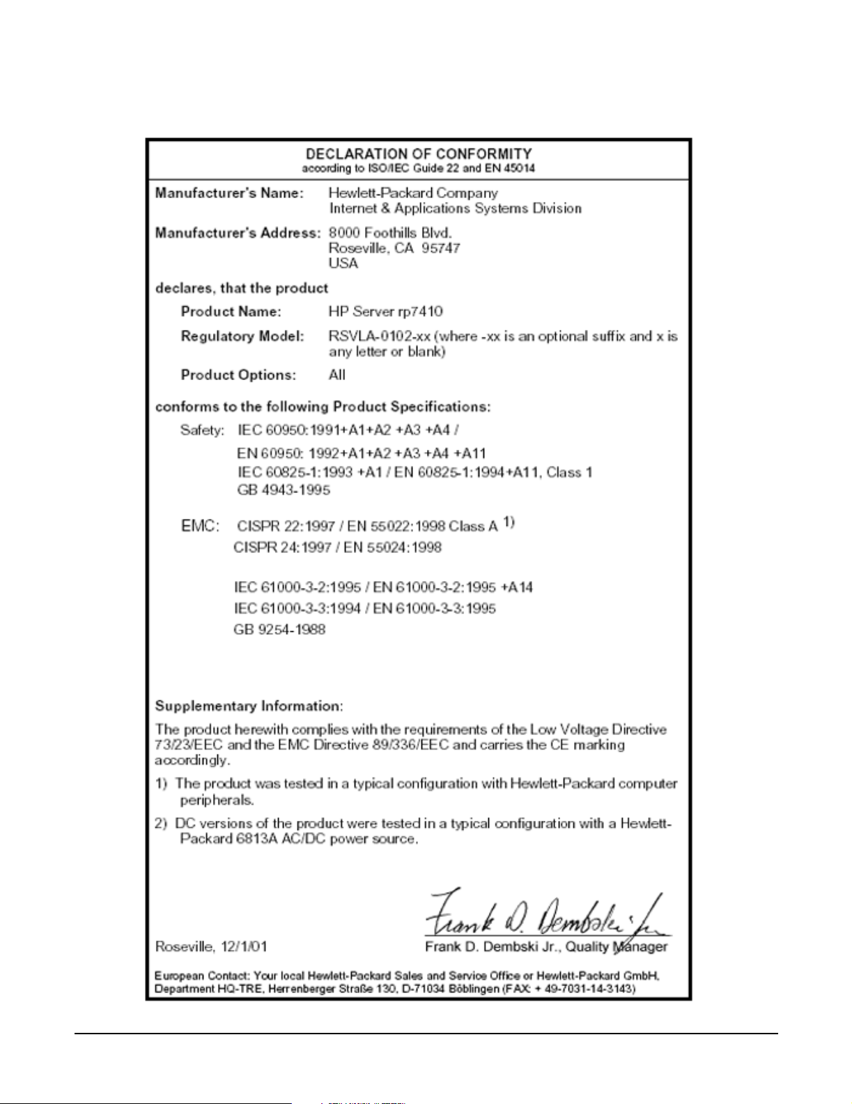
Figure 1 Declaration of Conformity
xi
Page 16

USA Radio Frequency Interference
FCC Notice
The Federal Communications Commission (in 47 CFR Part 15 subpart B) has specified that the following
notice be brought to the attention of the users of this product.
NOTE This equipment has been tested and found to comply with the limits for a Class A digital
device, pursuant to Part 15 of the FCC Rules. These limits are designed to provide reasonable
protection against harmful interference when the equipment is operated in a commercial
environment. This equipment generates, uses, and can radiate radio frequency energy and, if
not installed and used in accordance with the instruction manual, may cause harmful
interference to radio communications. Operation of this equipment in a residential area is
likely to cause harmful interference in which case the user will be required to correct the
interference at his own expense.
The user is cautioned that changes or modifications not expressly approved by Hewlett-Packard could result
in the equipment being noncompliant with FCC Class A requirements and void the user’s authority to
operated the equipment.
Japanese Radio Frequency Interference
VCCI
This equipment is in the Class A category information technology equipment based on the rules of Voluntary
Control Council For Interference by Information Technology Equipment (VCCI). When used in a residential
area, radio interference may be caused. In this case, user may be required to take appropriate corrective
actions.
Figure 2 Japanese RFI
xii
Page 17

Korean RFI Statement
Certification Number: E - AAAAA - BB - CCCC
• E: EMC registration
• AAAAA: equipment codes (RRL notice, 2000.10.26)
• BB: certification year
• CCCC: registration number
Figure 3 Korean RFI
Translation
Class A Equipment:
Please note that this equipment has been approved for business purpose with regards to electromagnetic
interference, if purchased un error for use in residential area, you may wish to exchange the equipment where
you purchase it.
Class B Equipment:
Please note that this equipment has been approved for non-business with regards to electromagnetic
interference. So, this equipment can be allowed to use all area as well as residential area.
European Union RFI Statement
This is a Class A product. In a domestic environment this product may cause radio interference in which case
the user may be required to take adequate measures.
Canada RFI Statement
This Class A digital apparatus complies with Canadian ICES-003.
Notice relative aux interférences radioélectriques (Canada)
Cet appareil numéric de la classe A est conforme à la norme NMB-003 du Canada.
xiii
Page 18

BSMI (Taiwan Area)
This product is fully compliant to CNS 13438 (CISPR 22: 1993) Class A. The EMC label is in the form shown
in Figure 4.
Figure 4 Taiwan Area EMC
NOTE Electrical practices and suggestions in this guide are based on North American practices. For
countries outside North America, local electrical codes will take precedence over North
American electrical codes.
An example would be the recommendation that the PE (protective earthing) conductor be green
with yellow stripes. This requirement is a North American directive and does not override the
local code requirements for a country outside North America.
Throughout this manual, the [LAHJ] acronym will be used to indicate Local Authority Has Jurisdiction.
Acoustics (Germany)
Acoustic Noise (A-weighted Sound Pressure Level LpA) measured at the bystander position, normal
operation, to ISO 7779: LpA = 59 dB.
Geräuschemission (Deutschland)
Lärmangabe (Schalldruckpegel LpA) gemessen am fiktiven Arbeitsplatz bei normalem Betrieb nach
DIN 45635, Teil 19: LpA = 59 dB.
IT Power System
This product has not been evaluated for connection to an IT power system (an AC distribution system having
no direct connection to earth according to IEC 60950).
TT, TN-C, and TN-C-S Power Systems
These products should not be connected to power systems that switch open the return lead when the return
lead also functions as the protective earth (PE). A separate PE ground wire must be connected to the
equipment at the designated PE terminal tie point.
xiv
Page 19

Installation Conditions
See installation instructions before connecting this equipment to the input supply.
Voir la notice d’installation avant de raccorder au réseau.
WARNING NORDIC Class 1 Equipment
Denmark: Før tilslutning af de øvrige ledere, se medfølgende
installationsvejledning.
WARNING NORDIC Class 1 Equipment
Sweden: Apparaten skall anslutas till jordat uttag, när den ansluts till ett nätverk.
Network Connected Equipment
The installation must provide a ground connection for the network equipment.
CAUTION Sweden: Apparaten skall anslutas till jordat uttang när deb abskuts till ett nätverk.
CAUTION Norway: Apparaten skall anslutas till jordat uttang nar deb abskuts till ett natverk.
xv
Page 20

Lithium Battery Caution
WARNING Observe the correct polarity when changing the lithium battery. There is a danger of
explosion if battery is installed incorrectly.
Replace only with the same or equivalent type recommended by the manufacturer.
Dispose of used batteries according to the manufacturer’s instructions and local
disposal requirements.
IMPORTANT Switzerland: Annex 4.10 of SR 814.013 applies to batteries.
Australian C-Tick Label
Figure 5 C-Tick Label
xvi
Page 21

Laser Safety
NOTE If a Fibre Channel I/O card is present, the following laser safety statement applies.
This product contains a laser internal to the Optical Link Module (OLM) for connection to the Fibre
communications port.
In the USA, the OLM is certified as a Class 1 laser product conforming to the requirements contained in the
Department of Health and Human Services (DHHS) regulation 21 CFR, Subchapter J. The certification is
indicated by a label on the plastic OLM housing.
Outside the USA, the OLM is certified as a Class 1 laser product conforming to the requirements contained in
IEC 60825-1:1993 and EN 60825-1:1994, including Amendment 11:1996.
NOTE If a DVD is present, the following laser safety statement applies.
This product contains a laser internal to the Digital Versatile Disc (DVD) housing.
In the USA, the DVD is certified as a Class 1 laser product conforming to the requirements contained in the
Department of Health and Human Services (DHHS) regulation 21 CFR, Subchapter J. The certification is
indicated by a label on the DVD housing.
Outside the USA, the DVD is certified as a Class 1 laser product conforming to the requirements contained in
IEC 60825-1:1993+A1 and EN 60825-1:1994+A11.
xvii
Page 22

xviii
Page 23

1 Introduction
The hp rp7410 is a member of Hewlett-Packard’s business-critical computing platform family: a mid-range,
mid-volume server, positioned as an upgrade to the current N-Class product in the PL-1X product line. It
provides increased performance over its predecessor but in a smaller volume. Its shallower depth allows it to
fit in a standard rack. In addition to the hp rp7410, Hewlett-Packard offers a series of cost-effective servers
based on the hp rp7410 with somewhat less performance. See “hp rp7405 Servers” on page 5.
Chapter 1
1
Page 24

Introduction
hp rp7405/rp7410 Overview
hp rp7405/rp7410 Overview
The hp rp7405/rp7410 is a 10U, 8-way SMP, rack-mount server that accommodates up to 32 GB of memory (64
GB available at a later date); PCI-4X I/O; and internal peripherals including disks and DVD/tape. Its high
availability features include N+1 hot-pluggable fans and power, redundant power cords, and hot-pluggable
PCI cards and internal disks. It uses the PA8700 PA-RISC processors.
Figure 1-1 hp rp7405/rp7410 Server (front view)
2
Chapter 1
Page 25

Figure 1-2 hp rp7405/rp7410 Server (without front bezel)
Introduction
hp rp7405/rp7410 Overview
Improvements over its predecessor, N4000, include:
• Better availability and up time
• Depth optimized (shallower, fewer racking issues)
• Performance density increase
• Performance increase
• Internal removable media
• More internal disks
• Optimal power cord quantity (2 min., 4 max)
• Enabled for cell hot-plug, dual-partition, dual and/or redundant MP Core I/O
• More PCI slots (up to 16)
• Upgradeable to PCI-X
• Superset of MP Core I/O functionality
Cell Board
The cell board contains the processors, main memory, and the CC ASIC that interfaces the processors and
memory to the off-board I/O. The CC provides a crossbar connection, which allows communication with other
cell boards in the system. It connects to the PDH and SINC hardware. Each cell board holds up to 16 DIMMS.
There can be one or two cell boards installed in a server. The cell boards have hot-plug capability.
Chapter 1
3
Page 26

Introduction
hp rp7405/rp7410 Overview
System Backplane
The system backplane comprises the system clock generation logic, the system reset generation logic,
DC-to-DC converters, power monitor logic, and two Local Bus adaptor (LBA) link-to-PCI converter ASICs. It
also includes connectors for attaching the cell boards, PCI backplane, MP Core I/O MP/SCSI boards, SCSI
cables, bulk power, chassis fans, front panel display, intrusion switches, and the system scan card. Unlike
Superdome or the rp8400, there are no XBC chips on the system backplane. The “crossbar-less” back-to-back
CC connection increases performance and reduces costs.
There are only two sets of cell board connectors, because the server has only two cells
Also, only half of the MP Core I/O board set connects to the system backplane. The MP/SCSI boards plug into
the backplane, while the LAN/SCSI boards plug into the PCI Backplane.
I/O Subsystem
All of the I/O is integrated into the system by way of the PCI busses. The CC on each cell board communicates
with one SBA over the SBA link. The SBA link consists of both an inbound and an outbound link with an
effective bandwidth of approximately 1 GB/sec. The SBA converts the SBA link protocol into “ropes”. SBA can
support up to 16 of these high-speed bi-directional links for a total aggregate bandwidth of approximately 4
GB/sec. The LBA acts as a bus bridge, supporting either one or two ropes, and capable of driving either
PCI-2x Turbo (33 MHz x 64 bits) or PCI-4 Twin Turbo (66 MHz x 64 bits) respectively.
4
Chapter 1
Page 27

Introduction
hp rp7405 Servers
hp rp7405 Servers
Hewlett-Packard offers a cost-effective server based on the hp rp7410 by employing a reduced number of
processors, memory, core I/O, or power supplies as indicated in Table 1-1.These servers provide a somewhat
reduced performance than the fully functional hp rp7410 servers.
Table 1-1 hp rp7405 Servers
Server Product Number Description
rp7405 2-way system A7111A Includes rp7405 SMP base system, two 650-MHz PA-RISC
processors, 4-GB memory (2 x 2GB memory modules), two
73-GB 10k internal disks, one DVD drive, one cell board, one
core I/O, and two power supplies
rp7405 4-way system A7112A Includes rp7405 SMP base system, four 650-MHz PA-RISC
processors, 8-GB memory (4 x 2 GB memory modules), four
73-GB 10k internal disks, one DVD drive, two cell boards,
two core I/O, and two powers supplies
rp7405 8-way system A7113A Includes rp7405 SMP base system, eight 650-MHz PA-RISC
processors, 16-GB memory (8 x 2 GB memory modules), four
73-GB 10k internal disks, one DVD drive, two cell boards,
two core I/O, and two power supplies
These servers may be upgraded with additional processors/cell boards, memory, core I/O, etc. according to the
corporate price list.
In addition, these servers may be upgraded to fully functional hp rp7410 servers with the kits given in
Tab le 1- 2 .
Table 1-2 hp rp7405-to-rp7410 Upgrades
Kit Description Upgrade Part Number
Upgrade kit from 2-way rp7405 to rp7410 750 MHz upgrade A7144A
875 MHz upgrade A7145A
Upgrade kit from 4-way rp7405 to rp7410 750 MHz upgrade A7146A
875 MHz upgrade A7147A
Upgrade kit from 8-way rp7405 to rp7410 750 MHz upgrade A7148A
875 MHz upgrade A7149A
Chapter 1
5
Page 28

Introduction
Detailed hp rp7405/rp7410 Description
Detailed hp rp7405/rp7410 Description
Figure 1-3 hp rp7410 8-Way Block Diagram
6
Chapter 1
Page 29

Introduction
Detailed hp rp7405/rp7410 Description
Cell Board
The cell board contains the processors, main memory, and the cell controller (CC) ASIC that interfaces the
processors and memory to the off-board I/O. Shown in Figure 1-4 is the CC. This is the heart of the cell board.
The CC provides a crossbar connection, which allows communication with other cell boards in the system. It
connects to the PDH and SINC hardware. Each cell board holds up to 16 DIMMs. There can be one or two cell
boards installed in an system. The cell boards have hot-plug capability.
Figure 1-4 Cell Controller
Figure 1-5 Cell Board
Chapter 1
7
Page 30

Introduction
Detailed hp rp7405/rp7410 Description
The hp rp7405/rp7410 has a 48V distributed power system and receives the 48V power from the system
backplane board. The cell board contains DC-to-DC converters to generate the required voltage rails. The
DC-to-DC converters on the cell board do not provide N+1 redundancy.
The cell board contains several major buses including:
• Runway buses for each of the four processors
• Two memory buses (one going to each half of the main memory array)
• Incoming and outgoing I/O bus that goes off board to a SBA chip
• Incoming and outgoing crossbar bus that goes off board to the other cell boards
• PDH bus that goes to the PDH/SINC circuitry
All of these buses come together at the CC chip.
Due to space limitations on the cell board the PDH/SINC circuitry resides on a riser board that plugs at a
right angle into the cell board. The cell board also includes clock circuits, test circuits and de-coupling
capacitors.
Figure 1-6 shows a simplified view of the memory subsystem. It consists of two independent access paths,
each path having its own address bus, control bus, data bus, and DIMMs. In practice, the CC runs the two
paths 180 degrees out of phase with respect to each other to facilitate pipelining in the CC. Address and
control signals are fanned out through register ports to the SDRAMs on the DIMMs.
Data transferred between the CC and SDRAM passes through custom VLSI circuits (M2) that are bit-sliced;
four form one 72-bit CC memory data bus. These circuits perform speed and width conversion between the
SDRAM and MID busses. They also perform the write (tag update) portion of a read-modify-write (RMW)
access. The CC memory data busses are bi-directional and run at 250 MT/s (million transfers per second).
These links are self-clocked in that a pair of clock strobes is passed along with the data so that phase
realignment can be done by the receiver.
Figure 1-6 Memory Subsystem
8
Chapter 1
Page 31

Introduction
Detailed hp rp7405/rp7410 Description
PDH Riser Board
The PDH riser board is a daughter card for the cell board. It contains a micro-processor memory interface
microcircuit, processor-dependent hardware (PDH) including the processor dependant code (PDC) Flash
memory, and a manageability micro-controller, called SINC, with associated circuitry. The PDH obtains cell
board configuration information from cell board signals and from the cell's LPM. See the PDH Riser Board
ERS for operational details.
The memory interface microcircuit is the heart of the PDH. It provides the CC access to the PDH space by a
4-bit, 50-75 MHz bus. This microcircuit also supports an interrupt mechanism to the CC that can interrupt a
processor for the PDH. It provides access to the FLASH ROM and scratch RAM memory chips together with
the external registers and an interface to an I
the system. It also controls system reset and initialization signals, as well as the low-level debugger (LDB)
port, UART, semaphore register, and GPIO pins. It is the primary master for a Serial Presence Detect bus.
The PDH supports up to 4 MB of address space for ROM (FLASH) to hold the PDC firmware.
The non-volatile memory and scratch RAM have been combined and placed in a 512KB battery-backed SRAM
DIMMs
Custom designed by Hewlett-Packard, each DIMM contains 36x4 SDRAM memory components similar to
PC-133 memory but qualified to run at 125MHz. They have an low-voltage TTL interface. The CEC does not
support traditional DRAMs.
2
C micro controller (SINC) that monitors sensors throughout
The hp rp7405/rp7410 supports DIMMs with 128, 256, 512, and 1024 Mbit devices. Table 1-3 shows each
DIMM supported with its associated capacity, the resulting total system capacity, and the memory component
density.
DIMMs must be loaded in sets of four at specific locations. For best performance, loading sets of eight DIMMs
is recommended.
Table 1-3 hp rp7405/rp7410 DIMMs
DIMM Capacity Total Capacity Memory Component Density
512 Mbyte 16 Gbytes 128 Mbit
1G Byte 32 Gbytes 256 Mbit
Main Memory Performance Latency to main memory is an important parameter in determining overall
system performance. With memory busses running at 125 MHz, the latency for a page hit is 8.5 cycles (68ns),
the latency for a page closed is 11.5 cycles (92ns), and the latency for a page miss is 14.5 cycles (116ns).
Cells and nPartitions
NOTE In the following discussion, the term “cell” refers to a cell board.
A cell board that has an I/O link to a bootable device and a console (usually supplied by an MP Core I/O card)
is a potential boot cell. The cell that contains the boot console I/O path is the called the root cell. Both cells are
potential root cells. The primary or default root cell in a single nPartition system is the bottom cell (cell 1).
An nPartition (also called a Protection Domain) is a cell(s) running the same OS and sharing processes and
memory space among the components. Each nPartition must have one root cell and may have both. The hp
rp7405/rp7410 has only two possible nPartition configurations: single or dual. The additional cell that may be
part of the nPartition does not require I/O links nor MP Core I/O cards.
Chapter 1
9
Page 32

Introduction
Detailed hp rp7405/rp7410 Description
In the single nPartition case, if two cells are present, either cell may be the root cell, assuming the both cells
have MP Core I/O functionality present. If only one cell is present, that cell is the root cell (and should be cell
1).
In the dual nPartition case (two cells required), each nPartition consists of one cell, and each cell must be a
root cell. The ability to interconnect two cells in one nPartition or isolate the cells in a dual nPartition system
provides system configuration flexibility. System partitioning is configured by the system management
processor.
Internal Disk Devices for hp rp7405/rp7410
As Figure 1-4 shows, in an hp rp7405/rp7410 cabinet the top internal disk drives connect to cell 1 through the
MP Core I/O for cell 1 (for 1/0/0/3/0.6) and the LAN/SCSI card in slot 1_8 (I/O chassis 1 slot 8, for
1/0/1/0/0/1/1.6). Both of the bottom disk drives (0/0/0/3/0.6 and 0/0/0/3/0.5) connect to cell 0 through the MP
core I/O for cell 0. A CD/DVD-ROM drive or DAT drive connects to cell 1 through the core I/O card for cell 1,
thus it can be accessed through the cell 1 nPartition only.
Figure 1-7 Internal Disks
Drive 1-1
Path: 1/0/0/3/0.6
Drive 1-2
Path: 1/0/1/0/0/1/1.6
Removable media path
DVD: 1/0/0/3/1.2
DAT: 1/0/0/3/1.3
Drive 0-2
Path: 0/0/0/3/0.5
Drive 0-1
Path: 0/0/0/3/0.6
10
Chapter 1
Page 33

Introduction
Detailed hp rp7405/rp7410 Description
System Backplane
The system backplane comprises the system clock generation logic, the system reset generation logic,
DC-to-DC converters, power monitor logic, and two LBA link-to-PCI converter ASICs. It also includes
connectors for attaching the cell boards, PCI backplane, MP Core I/O MP/SCSI boards, SCSI cables, bulk
power, chassis fans, front panel display, intrusion switches, and the system scan card.
Figure 1-8 System Backplane Block Diagram
System backplane
MP Core I/O
MP/SCSI
PCI backplane
Cell board 0
MP Core I/O
MP/SCSI
Cell board 1
Cell boards are perpendicular
to the system backplane.
Bulk power supply
Only half of the MP Core I/O board set connects to the system backplane. The MP/SCSI boards plug into the
backplane, while the LAN/SCSI boards plug into the PCI backplane.
Clocks and Reset
The system backplane contains reset and clock circuitry that propagates through the whole system. The
central clocks drive all major chip set clocks. Therefore, these circuits represent a system wide single point of
failure.
I/O Subsystem
The cell board-to-I/O path runs from the CC to the SBA, from the SBA to the ropes, from the ropes to the LBA,
and from the LBA to the PCI buses. The CC on each cell board communicates with one SBA over the SBA
link. The SBA link consists of both an inbound and an outbound link with an effective bandwidth of
approximately 1 GB/sec. The SBA converts the SBA link protocol into “ropes.” The SBA can support up to 16
of these high-speed bi-directional rope links for a total aggregate bandwidth of approximately 4 GB/sec. The
LBA acts as a bus bridge, supporting either one or two ropes and capable of driving either PCI-2x Turbo (33
MHz x 64 bits) or PCI-4 Twin Turbo (66 MHz x 64 bits) respectively
Chapter 1
11
Page 34

Introduction
Detailed hp rp7405/rp7410 Description
.
Figure 1-9 I/O Subsystem Architecture
The server supports two internal SBAs. The SBAs generate 32 rope busses (16 per SBA). The 32 available
internal rope busses are divided in the following manner:
• Two ropes are routed as single rope bundles to support PCI-2x Turbo (264 MB/sec. bandwidth, 64-bit
transfers at 33 MHz) for the MP Core I/O boards for SCSI/LAN.
• Two ropes are routed as single rope bundles to two LBAs to support two slots operating at PCI-2x for
MP/SCSI.
• The remaining 28 ropes are bundled in two rope pairs to 14 LBAs to support 14 slots operating at PCI-4x
(528 MB/sec., 64-bit transfers at 66 MHz).
The hp rp7405/rp7410 uses Hewlett-Packard’s proprietary adaptive signaling concept, also known as the
Universal PCI slot concept (not to be confused with the Universal PCI card). Circuitry on the backplane
senses a standard connector, keyed for 5V, to determine the type of the cards inserted. The circuitry controls
the voltage rail supplied to the connector for powering the card’s I/O pads, VIO. The card can either be of the
5V only, or universal type. 5V only cards require VIO to be 5V, whereas universal cards operate 5V as well as
3.3V. To take advantage of the 66-MHz potential of universal cards, one must operate those cards at 3.3V. The
control circuitry on the backplane, therefore, provides 5V to the slot when a 5V-only card is present, or 3.3V
when a universal card is present. Firmware controls the setting of the slot’s clock rate.
12
Chapter 1
Page 35

Introduction
Detailed hp rp7405/rp7410 Description
This concept allows maximum connectivity for mainstream 5V-only, 33 MHz, 32 bit (PCI-1x) and 64-bit
(PCI-2x) cards, as well as full I/O bandwidth utilization through the use of 64-bit, 66 MHz (PCI-4x) universal
cards.
Table 1-4 PCI Slot Types
Slot# Device:
0_1 PCI-4x, Twin Turbo 64-bit, 66 MHz, 3.3V-only, 3.3V connector, Hot Swap Slot.
0_2 PCI-4x, Twin Turbo 64-bit, 66 MHz, 3.3V-only, 3.3V connector, Hot Swap Slot.
0_3 PCI-4x, Twin Turbo 64-bit, 66 MHz, 3.3V-only, 3.3V connector, Hot Swap Slot.
0_4 PCI-4x, Twin Turbo 64-bit, 66 MHz, 3.3V-only, 3.3V connector, Hot Swap Slot.
0_5 PCI-4x, Twin Turbo 64-bit, 66 MHz, 3.3V-only, 3.3V connector, Hot Swap Slot.
0_6 PCI-4x, Twin Turbo 64-bit, 66 MHz, 3.3V-only, 3.3V connector, Hot Swap Slot.
0_7 PCI-4x, Twin Turbo 64-bit, 66 MHz, 3.3V-only, 3.3V connector, Hot Swap Slot.
0_8 PCI-2x, Turbo 64-bit, 33 MHz, Adaptive Signaling, 5V connector, Hot Swap Slot.
1_1 PCI-4x, Twin Turbo 64-bit, 66 MHz, 3.3V-only, 3.3V connector, Hot Swap Slot.
1_2 PCI-4x, Twin Turbo 64-bit, 66 MHz, 3.3V-only, 3.3V connector, Hot Swap Slot.
1_3 PCI-4x, Twin Turbo 64-bit, 66 MHz, 3.3V-only, 3.3V connector, Hot Swap Slot.
1_4 PCI-4x, Twin Turbo 64-bit, 66 MHz, 3.3V-only, 3.3V connector, Hot Swap Slot.
1_5 PCI-4x, Twin Turbo 64-bit, 66 MHz, 3.3V-only, 3.3V connector, Hot Swap Slot.
1_6 PCI-4x, Twin Turbo 64-bit, 66 MHz, 3.3V-only, 3.3V connector, Hot Swap Slot.
1_7 PCI-4x, Twin Turbo 64-bit, 66 MHz, 3.3V-only, 3.3V connector, Hot Swap Slot.
1_8 PCI-2x, Turbo 64-bit, 33 MHz, Adaptive Signaling, 5V connector, Hot Swap Slot.
MP/SCSI MP Core I/O Board
The hp rp7405/rp7410 accommodates two sets of MP Core I/O functionality. Each MP Core I/O board set
consists of a MP/SCSI board and a Procurium LAN/SCSI board. At least one MP/SCSI board is required
(independent of partitions) An additional MP/SCSI board can be added as well (and is required in a dual
partition system). Both MP/SCSI boards are oriented vertically and plug into the system backplane. The
MP/SCSI board incorporates a dual Ultra160 SCSI controller and is hot pluggable.
Procurium LAN/SCSI Board
At least one Procurium LAN/SCSI board is required for the minimum system configuration; two are required
in a dual partition system. The Procurium board is a standard PCI form factor card with PCI card edge
connectors. The PCI backplane has one slot location reserved for the required Procurium board and another
that can accommodate either a Procurium board or any other supported add-in PCI card. The Procurium
board is hot pluggable.
Chapter 1
13
Page 36

Introduction
Detailed hp rp7405/rp7410 Description
Mass Storage (Disk) Backplane
Internal mass storage connections (to disks) are routed on the mass storage backplane, having connectors and
termination logic. All disks are hot pluggable. The hp rp7405/rp7410 accommodates one internal removable
media device. Therefore, only one power connector for a removable media device is required on the mass
storage backplane. The mass storage backplane incorporates a circuit that allows power to the internal
removable media device to be programmatically cycled.
Package Description
Dimensions
The dimensions of the hp rp7405/rp7410 are as follows:
• Width: 44.45 cm (17.5 inches), constrained by EIA standard 19 inch racks.
• Depth: Defined by cable management constraints to fit into standard 36 inch deep racks (Rittal/Compaq,
Rosebowl I):
25.5 inches from front rack column to PCI connector surface:
26.7 inches from front rack column to MP Core I/O connector surface
30 inches overall package dimension, including 2.7 inches protruding in front of the front rack columns.
• Height: 10U – 5.4 cm = 43.91 cm (17.287 inches). This is the appropriate height for a product that
consumes 10U of rack height while allowing adequate clearance between products directly above and
below this product. Fitting four server units per 2 m rack and upgrade of current 10U height products in
the future are the main height constraints.
System Chassis
The mass storage section located in the front allows access to removable mass storage devices without
removal of the bezel (not shown.) This is especially helpful when the system is mounted in the lowest position
in a rack. The mass storage bay accommodates one 5.25-inch removable media device and up to four 3.5-inch
hard drives. The front panel display board, containing LEDs and the system power switch, is located directly
above the 5.25-inch removable media bay.
Below the mass storage section and behind a removable bezel are two PCI DC-to-DC power converters.
The bulk power supply section is partitioned by a sealed metallic enclosure located in the bottom of the
package. This enclosure houses the 2N fully redundant BPSs.
14
Chapter 1
Page 37

Figure 1-10 Right-Front View of hp rp7405/rp7410
Front panel
display board
Introduction
Detailed hp rp7405/rp7410 Description
PCI cards
Cell boards
PCI DC-to-DC
converters
Bulk powers supplies
The PCI I/O card section, located towards the rear, is accessed by removing the top cover.
The PCI OLR fan modules are located in front of the PCI cards. These six 9.2 cm fans are housed in plastic
carriers. They are configured in two rows of three fans.
The MP/SCSI MP Core I/O boards are positioned vertically at the rear of the chassis.
The PCI card bulkhead connectors are located in the top rear portion of the product volume.
Four OLR system fan modules, externally attached to the chassis, are 15 cm (6.5-inch) fans. Two fans are
mounted on the front surface of the chassis and two are mounted on the rear surface.
Redundant line cords attach to the floating AC connector module at the bottom rear. Two 20-amp cords are
required to power the server. Two additional line cords provide redundancy.
Slide
A cable harness that connects from the rear of the BPSs to the system backplane provides DC power
distribution.
Access the system backplane is accomplished by removing the left side cover. The system backplane inserts by
a guide/insertion mechanism using a single large jack screw assembly.
SCSI ribbon-cable assemblies route from the mass storage area to the backside of the system backplane and
to the Procurium PCI MP Core I/O card.
Chapter 1
15
Page 38

Introduction
Detailed hp rp7405/rp7410 Description
Cell boards are accessed from the right side of the chassis behind a removable side cover.
Figure 1-11 Left-Rear View of hp rp7405/rp7410
System backplane
MP Core I/O MP/SCSIs
16
Chapter 1
Page 39

2 Installation
Chapter 2
17
Page 40

Installation
Unpacking the Server
Unpacking the Server
Hewlett-Packard shipping containers are designed to protect their contents under normal shipping
conditions. After the equipment arrives, carefully inspect each carton for signs of shipping damage. A tilt
indicator is installed on each carton shipped. The beads in the indicator will roll to the upper position if the
container has been tilted to an angle that could cause equipment damage. The tilt indicator itself will have
two windows and each window under normal conditions will show four beads present. If a carton has been
mishandled, accidentally dropped, or knocked against something, the tilt indicator will indicate missing
beads. If damage is found, document the damage with photographs and contact the transport carrier
immediately.
Examine the server cabinet for visible shipping damage. After unpacking the cabinet, check for damage that
may have been obscured by the shipping container. If damage is found after visual inspection, document the
damage with photographs and contact the transport carrier immediately.
If the equipment has any damage, a damage claim form must be obtained by the customer from the shipping
representative. The customer should complete the form and return it to the shipping representative.
NOTE The server may come already racked, or ready for rack installation.
Unpacking a Racked Server
This section contains information pertaining to unpacking the cabinet.
WARNING Wear protective glasses while cutting the plastic bands around the shipping
container. These bands are under tension. When cut, they can spring back and cause
serious eye injury.
NOTE Position the pallet allowing for enough space to roll the cabinet off the pallet before starting.
Remove the cabinet using the following procedure:
Step 1. Cut the polystrap bands around the shipping container.
Step 2. Lift the cardboard top cap from the shipping box. See Figure 2-1.
Step 3. Remove the corrugated wrap from the pallet.
Step 4. Remove the packing materials.
18
Chapter 2
Page 41

Installation
Unpacking the Server
CAUTION The plastic wrapping material should be cut off rather than pulled off. Pulling the
plastic covering off represents an ESD hazard.
Figure 2-1 Removing the Polystraps and Cardboard
Chapter 2
19
Page 42

Installation
Unpacking the Server
Step 5. Remove four bolts holding down the ramps and remove the ramps. See Figure 2-2.
Figure 2-2 Removing the Shipping Bolts and Plastic Cover
20
Chapter 2
Page 43

Unpacking the Server
Step 6. Remove the six bolts from the base attaching the rack to the pallet. See Figure 2-3.
Figure 2-3 Preparing to Roll Off the Pallet
Installation
WARNING Make sure that the leveling feet on the rack are raised before you roll the
rack down the ramp and any time you roll the rack on the casters. Use
caution when rolling the cabinet off the ramp. A single server in the cabinet
weighs approximately 400 pounds. It is strongly recommended that two
people roll the cabinet off the pallet.
Chapter 2
21
Page 44

Installation
Unpacking the Server
Securing the Cabinet
Once in position, secure and stabilize the cabinet using the leveling feet at the corners of the base and install
the anti-tip mechanisms on the bottom front and rear of the rack.
Figure 2-4 Securing the Cabinet
Unpacking a Non-Racked Server
NOTE Hewlett-Packard recommends the use of a lifter, such as a RONI Company model 17000 SP 400
lifting device, when moving a non-racked system, shown in Figure 2-5. If no lifter is available,
install the lift handle panels provided with the system.
Unloading with a Lifter
Use the following procedure to unload the server from the pallet using a lifter.
WARNING Use caution when using a lifter. Because of the weight of the server, it must be
centered on the lifter forks before raising it off the pallet to avoid injury.
Never extend more than one server from the same cabinet while installing or
servicing either an hp rp7405/rp7410 or another server product. Failure to follow
these instructions could result in the cabinet tipping over.
22
Chapter 2
Page 45

Figure 2-5 RONI Lifter
Installation
Unpacking the Server
Step 1. Follow the instructions on the outside of the server packaging to remove the banding and carton top
from the server pallet.
Figure 2-6 Server with Shipping Box Removed
Step 2. Remove all cartons from the pallet leaving only the server.
Chapter 2
23
Page 46

Installation
Unpacking the Server
Step 3. Observe Figure 2-7. Remove the two foam cushion for lift access.
Figure 2-7 Remove Cushions for Lift Access
Remove cushion
Remove cushion
Clearance for RonI lift is 28”x5”
Step 4. Insert the lifter forks under the server.
Step 5. Carefully roll the lift forward until it is fully positioned against the side of the server.
24
Chapter 2
Page 47

Step 6. Slowly raise the server off the pallet until it clears the pallet cushions.
Figure 2-8 Raising a Server Off the Pallet
Installation
Unpacking the Server
Step 7. Roll the lifter and server away from the pallet. Do not raise the server any higher than necessary
when moving it over to the rack.
Figure 2-9 Lifting the Server to the Rack
NOTE If you are installing the system in a rack, refer to the hp J1530A Rack Integration Kit
Installation Guide.
Chapter 2
25
Page 48

Installation
Unpacking the Server
Unloading with Lift Handle Panels
WARNING Use this procedure only if no Hewlett-Packard approved lift is available. This
procedure should only be attempted by two (2) authorized Hewlett-Packard service
people.
Before attempting this procedure, it is recommended that you first remove all Cell
Boards and AC power supplies. Instructions for removing these components can be
found in the Removal and Replacement chapter of the service manual. Check with
local safety regulations before attempting to move the system using the lift handle
panels.
Failure to observe these precautions can cause serious injury to personnel or
damage to equipment.
CAUTION Unpack the server in an ESD safe environment. Observe all ESD safety precautions before
attempting this procedure. Failure to follow ESD safety precautions could result in damage to
the server.
Step 1. Remove both side covers. If present, remove the front panel.
Step 2. Locate lift handles and remove from storage plate.
Step 3. Orient lift handle panels such that when installed, the handles hang downward at 90 degrees and
lock in a horizontal position during lifting.
Figure 2-10 Positioning the Lift handles
26
Chapter 2
Page 49

Installation
Unpacking the Server
Step 4. With one handle in each hand, install the pin end of the panel into the backside of the front rack
mount ears on the chassis.
Figure 2-11 Inserting the Pins Into the Rack
Step 5. Pull the spring plunger out, move the handles apart and install the shoulder washer end of the
panel into the keyway feature.
Figure 2-12 Lift Handles Mounted
Chapter 2
27
Page 50

Installation
Unpacking the Server
Step 6. Continue to pull the handles apart until the spring plunger snaps into final position. The spring
plunger will drop down into the recess position.
Step 7. Check that the handles are secure by pressing the handles together and moving back and forth.
Check to see if lift handle panel breaks free of chassis.
Step 8. Repeat the steps above for the other handle
Step 9. To lift the server, rotate the handles 90 degrees to horizontal position.
NOTE If you are installing the system in a rack, refer to the installation guide, hp J1530A,
rack installation kit (lower case intended).
Step 10. After moving the server, remove the lift handle panels from the chassis and reinstall the server
covers and front bezel. Refer to installation guide, hp J1530A, rack installation kit (lower case
intended).
Figure 2-13 Lifting the Server
Installing Server Into the Rack
Any hp rp7405/rp7410 server that is to be installed into a rack is shipped with equipment slides. With every
set of slides comes an installation guide: installation guide, hp J1530A, rack installation kit (lower case
intended). Follow the steps in this installation guide to determine where and how to place the server into the
rack.
28
Chapter 2
Page 51

Installation
Unpacking the Server
Installing the Cable Management Arm (CMA)
Once the server is installed in the rack, the CMA must be installed on the rear of the server. Follow the
instructions for installing the CMA can be found in the installation guide, hp J1530A, rack installation kit
(lower case intended).
Figure 2-14 Cable Management Arm
Cable Management Arm
Step 1. Attach CMA to the rack using T-25 Torx screws.
Figure 2-15 Attaching CMA to Rack
Chapter 2
29
Page 52

Installation
Unpacking the Server
Step 2. Attach the other end of the CMA to the server using the thumb screws that came with the CMA.
Figure 2-16 Attaching CMA to the Server
Installing Add-On Products
This section explains load orders and dependencies for add-on products. For physical installation procedures,
refer to that components replacement procedure in Chapter 4, “Removal and Replacement.”
If installing add-on products to an existing server, follow operating system backup and shutdown procedures
before powering off the server.
Cell Boards
The server requires at least one cell board to operate. Install the first cell board slot 1 (lower slot) and the
second cell board in slot 0 (upper). Cell Board 0 enables the PCI cards in Chassis 0 and Cell Board 1 enables
the PCI cards in Chassis 1.
MP Core I/O Cards
MP Core I/O consists of two cards that must be installed in pairs: the MP/SCSI and the LAN/SCSI.
The first (primary) set of MP Core I/O cards is installed as follows: MP/SCSI in MP/SCSI slot 1 (lower slot)
and LAN/SCSI in PCI slot 8 of Chassis 1 (from the rear, the extreme right-hand PCI slot).
The second set of MP Core I/O cards is installed as follows: MP/SCSI in MP/SCSI slot 0 and LAN/SCSI in PCI
slot 1 of Chassis 0. Cell Board 0 is required to enable the MP/SCSI slot 0 (upper slot) and LAN/SCSI slot 1 in
Chassis 0 (from the rear, the extreme left-hand PCI slot).
30
Chapter 2
Page 53

Installation
Unpacking the Server
Embedded Disks
The hp rp7405/rp7410 server can operate in the diskless (LAN boot) mode. If disks are to be installed, the top
two disks are driven by the primary MP Core I/O set. Install the first embedded disk in the top left location.
Install the second embedded disk in the top right location.
Figure 2-17 Embedded Disks
Drive 1-1
Path: 1/0/0/3/0.6
Drive 1-2
Path: 1/0/1/0/0/1/1.6
Drive 0-2
Path: 0/0/0/3/0.5
Drive 0-1
Path: 0/0/0/3/0.6
Chapter 2
31
Page 54

Installation
Unpacking the Server
Processors
Each cell board can hold up to four processors. Processor slots are numbered 0-3. Install processors in
ascending order: slot 0, 1, 2, and 3. It is not necessary to balance the number of processors across both cell
boards.
Figure 2-18 Cell Board (Two processors and CC Shown)
Cell Controller
Processor 1
Processor 0
DIMMs
Each cell board can hold up to four quads (or ranks) of DIMMs. A rank is a group of four DIMMs. Each DIMM
within a rank must be the same capacity. The slots within each rank are numbered a,b,c,d. Install DIMMs in
ascending order: rack 0, 1, 2 and 3. It is not necessary to balance the number of DIMMs across both cell
boards. For Example: one rank = slots 0a, 0b, 0c and 0d.
Valid Memory Configurations DIMMs must be loaded in sets of four at specific locations. For best
performance, loading sets of 8 DIMMs is recommended.
Processor 3
Processor 2
Table 2-1 hp rp7405/rp7410 DIMMs
DIMM Capacity Total Capacity Memory Component Density
512 Mbyte 16 GBytes 128 Mbit
1G Byte 32 Gbytes 256 Mbit
The hp rp7405/rp7410 is capable of supporting as little as 2 Gbytes of main memory using four 512 MByte
DIMMs and one cell board and as much as 32 Gbytes using all 16 DIMM slots on both cell boards with 1GB
DIMMs.
32
Chapter 2
Page 55

Installation
Unpacking the Server
Different densities of main DIMMs can be mixed within a system, but each set of four DIMMs must be
identical. A set of DIMMs is defined as the group of four DIMMs that must be loaded together on a cell board.
Each cell board has four sets of DIMM slots, and they must be populated in order. Figure 2-19 shows the order
in which the DIMM slots must be populated.
Figure 2-19 DIMM Loading Sequence
Block 1 shows the minimum memory configuration per cell board. Each cell board, therefore, could have up to
four different density DIMMs (if there were that many), as long as each set of four are identical. Box 2 and
Box 4 show the more optimal memory configurations, because loading DIMMs in sets of eight takes
advantage of the pipelined structure of the memory interface of the CC.
Chapter 2
33
Page 56

Installation
Connecting AC Input Power
Connecting AC Input Power
The hp rp7405/rp7410 has five line cord configurations:
• All four line cords
• Cords A0 and A1 only
• Cords B0 and B1 only
• Cords A0 and B0 only
• Cords A1 and B1 only
A single-line-cord configuration is not allowed.
Figure 2-20 Power Cord Configuration
A0 A1 B0 B1
The power cord configuration is passed to the operating system using the pwrgrd (Power Grid) command.
Each of the five selections in the pwrgrd command matches one of the configurations. The appropriate option
should be selected for the actual line cord configuration. With the correct configuration selected, the LEDs
should be green. when the pwrgrd command is invoked, the following menu is displayed.
IMPORTANT Options 1 and 2 are for Hewlett-Packard internal use only. Do not select these options.
prompt> pwrgrd
Power grid configuration preference.
1. Grid A only (Cords A0,A1 required)
2. Grid B only (Cords B0,B1 required)
3. Grids A & B (Cords A0,A1,B0,B1 required)
4. Cords A0 & B0 only
5. Cords A1 & B1 only
Select Option:
34
Chapter 2
Page 57

Installation
Connecting AC Input P ower
If two separate power sources are available, the two power supplies can be plugged into the separate power
sources, increasing system reliability should one power source fail.
Figure 2-21 Power Source vs. Power Distribution
BPS 0 BPS 1
A0
220 VAC*
A1
220 VAC*
B0
220 VAC*
B1
220 VAC*
Rear of Cabinet
*180-269 VAC
WARNING Voltage is present at various locations within the server whenever a power source is
connected. This voltage is present even when the main power switch is in the off
position. Failure to observe this warning could result in personal injury or damage
to equipment.
NOTE System firmware will prevent boot when a single power cord configuration is detected.
Chapter 2
35
Page 58

Installation
MP Core I/O Connections
MP Core I/O Connections
Each hp rp7405/rp7410 can have up to two MP Core I/O board sets installed. This allows for two partitions to
be operating, or allows for MP Core I/O redundancy in a single partition configuration. Each MP Core I/O
board set consists of two boards: the MP/SCSI board and the LAN/SCSI board. The MP/SCSI board is
oriented vertically and accessed from the back of the server. The LAN/SCSI is accessed from the PCI
expansion card bay. Only the primary MP core I/O board set (MP/SCSI slot 1 & LAN/SCSI slot 8, Chassis 1) is
required for a single partition implementation. The secondary MP/SCSI board is not necessary for full
operation, however, without the secondary MP/SCSI board only two internal disks can be accessed.
MP/SCSI Connections
The MP/SCSI board is required to update firmware, access the console, turn partition power on/off, access all
but one of the internal peripherals, and utilize other features of the system.
Connections to the MP/SCSI board include the following:
• DB25 Connector; via the M cable.
This RS232 connector provides connections for a local console, external modem, and a UPS. The server
end of the M cable terminates in a DB25 connector. The opposite side of the cable terminates in 3 DB9
connectors labeled CONSOLE, UPS, and REMOTE.
• 10/100 Base-T LAN RJ45 connector (for LAN and Web Console access).
This LAN uses standby power and is active when AC is present and the front panel power switch is off.
• Internal LVD Ultra 160 SCSI channel for connections to internal mass storage.
• Internal SE Ultra SCSI channel for connection to internal removable media device.
LAN/SCSI Connections
The LAN/SCSI board is a PCI form factor card that provides the basic external I/O connectivity for the
system.
Connections to the LAN/SCSI board include the following:
• PCI-X to PCI-X Bridge for multi-device compatibility
• Internal LVD Ultra 160 SCSI channel for connections to internal mass storage.
• External LVD Ultra 160 SCSI channel connected to a 68-pin VHDCI connector
• 10/100/1000 Base-T LAN RJ45 connector.
The primary LAN interface is located on the LAN/SCSI board installed in the rightmost slot when viewing
the system from the back.
Management Processor Access
NOTE In order to access the Management Processor for the initial installation, the M cable must first
be connected to the DB25 connector located on the Primary MP/SCSI board. The Primary
MP/SCSI board is located in the lower MP/SCSI board slot.
36
Chapter 2
Page 59

Installation
MP Core I/O Connections
Setting Up the CE Tool (PC)
The CE Tool is usually a laptop. It allows communication with the Management Processor (MP) in the hp
rp7405/rp7410. The MP monitors the activity of either a one partition or a multiple partition configuration.
During installation, communicating with the MP enables such tasks as:
• Verifying that the components are present and installed correctly
• Setting LAN IP addresses
• Shutting down cell board power
Communication with the MP is established by connecting the CE Tool to the Local RS-232 port on the MP
Core I/O card.
Setting CE Tool Parameters
After powering on the CE Tool, ensure the communications settings are as follows:
• 8/none (parity)
• 9600 baud
• na (Receive)
•na (Transmit)
Chapter 2
37
Page 60

Installation
MP Core I/O Connections
If the CE Tool is a laptop using Reflection 1, check or change these communications settings using the
following procedure:
1. From the Reflection 1 Main screen, pull down the Connection menu and select Connection Setup.
2. Select Serial Port.
3. Select Com1.
4. Check the settings and change, if required.
Go to More Settings to set Xon/Xoff. Click OK to close the More Settings window.
5. Click OK to close the Connection Setup window.
6. Pull down the Setup menu and select Terminal (under the Emulation tab).
7. Select any HP terminal type.
Preferred types are HP70092, HP70096 or HP70094, HP70098, VT100.
8. Click Apply.
This option is not highlighted if the terminal type you want is already selected.
9. Click OK.
Connecting the CE Tool to the Local RS-232 Port on the MP
This connection allows direct communications with the MP. Only one window can be created on the CE
Tool to monitor the MP. When enabled, it provides direct access to the MP and any partition.
Use the following procedure to connect the CE Tool to the Local RS-232 Port on the MP:
1. Connect one end of a null modem cable (9-pin to 9-pin) (Part Number 5182-4794) to the M cable connector
labeled CONSOLE.
2. Connect the other end of the RS-232 cable to the CE Tool.
Standby Power and Logging in to the MP
After connecting the serial device, it is possible to login to the Management Processor (MP). Housekeeping
power (also known as standby power) is generated as soon as AC power is applied to the server. Because the
MP uses standby power, it is possible to login to the MP even when the power switch is in the OFF position.
The power switch is a DC power switch that controls +48v DC.
Before powering up the hp rp7405/rp7410 server for the first time:
1. Verify that the AC voltage at the input source is within specifications for each hp rp7405/rp7410 being
installed.
2. If not already done so, power on the serial display device.
The preferred tool is the CE tool running Reflection 1.
To power up the MP, set up a communications link, and login to the MP:
1. Connect the server to AC power.
38
Chapter 2
Page 61

Installation
MP Core I/O Connections
On the front of the hp rp7405/rp7410, a solid green Standby Power, a solid green MP Present, and a
flashing amber Attention light will illuminate after about 30 seconds.
Figure 2-22 Front Panel Display
2. Check the bulk power supply LED for each BPS.
When on, the breakers distribute power to the BPSs. AC power is present at the BPSs:
• When power is first applied. Note the BPS LEDs will be flashing amber.
• After 30 seconds has elapsed. Note the flashing amber BPS LED for each BPS becomes a flashing
green LED
Refer to power cord policies to interpret LED indicators.
3. Login to the MP:
a. Enter Admin at the login prompt. This term is case sensitive.
It takes a few moments for the MP prompt to appear. If it does not, make sure the laptop serial device
settings are correct: 8 bits, no parity, 9600 baud, and na for both Receive and Transmit. Then, try
again.
b. Enter Admin at the password prompt. This term is case sensitive.
Chapter 2
39
Page 62

Installation
MP Core I/O Connections
The MP Main Menu appears:
Figure 2-23 MP Main Menu
MP login: Admin
MP password:
Welcome to the
rp7410
Management Processor
(c) Copyright 1995-2001 Hewlett-Packard Co., All Rights Reserved.
MP MAIN MENU:
CO: Consoles
VFP: Virtual Front Panel
CM: Command Menu
CL: Console Logs
SL: Show chassis Logs
HE: Help
X: Exit Connection
MP>
Configuring LAN Information for the MP
To set the MP LAN IP address:
1. At the MP Main Menu prompt (MP>), enter cm. From the MP Command Menu prompt (MP:CM>), enter
lc (for LAN configuration).
The screen displays the default values and asks if you want to modify them. It is a good idea to write
down the information, as it may be required for future troubleshooting.
NOTE If the Command Menu is not shown, enter q to return to the MP Main Menu, then enter cm
40
Chapter 2
Page 63

Enter lc and press the Return key. The following screen appears:
Figure 2-24 The lc Command Screen
Installation
MP Core I/O Connections
NOTE The value in the “IP address” field has been set at the factory. The customer must provide
the actual LAN IP address.
2. At the prompt, Do you want to modify the configuration for the customer LAN?, enter y.
The current IP address is shown; then the following prompt appears: Do you want to modify it? (Y/[N])
3. Enter y.
4. Enter the new IP address.
The customer shall provide this address for network interface 0.
5. Confirm the new address.
6. Enter the MP Network name.
This is the host name for the customer LAN. The name can be as many as 64 characters, and include
alpha numerics, - (dash), _ (under bar),. (period), or a space. It is recommended that the name be a
derivative of the complex name. For example, Acme.com_MP.
7. Enter the LAN parameters for Subnet mask and Gateway address.
This information shall come from the customer.
8. Once step 7 is completed, the system will indicate the parameters have been updated and return to the
MP Command Menu prompt (MP:CM>)
9. To check the LAN parameters and status, enter the ls command at the MP Command Menu prompt
(MP:CM>).
Chapter 2
41
Page 64

Installation
MP Core I/O Connections
10. A screen similar to the following will appear allowing verification of the settings:
Figure 2-25 The ls Command Screen
To return to the MP main menu, enter ma.
To exit the MP, enter x at the MP main menu.
Verifying Presence of the Cell Boards
To perform this activity, either connect to the management processor (MP) using a console or connect the CE
Tool (laptop) to the RS-232 Local port on the MP.
After login to the MP, verify that the MP detects the presence of all the cells installed in the cabinet. It is
important for the MP to detect the cell boards. If it does not, the partitions will not boot.
To determine if the MP detects the cell boards:
1. At the MP prompt, enter cm .
This displays the Command Menu. Among other things, the Command Menu allows one to view or modify
the configuration and/or look at utilities controlled by the MP.
To look at a list of the commands available, enter he. You may have to press Enter to see more than one
screen of commands. Use the Page Up and Page Down keys to view the previous or next screen of
commands. To exit the Help Menu, enter q.
2. From the command prompt (MP:CM>), enter du.
42
Chapter 2
Page 65

Installation
MP Core I/O Connections
The du command displays the MP Bus topology. A screen similar to the following appears:
Figure 2-26 The du Command Screen
3. There will be an asterisk (*) in the column marked MP.
4. Verify that there is an asterisk (*) for each of the cells installed in the cabinet, by comparing what is in the
Cells column with the cells physically located inside the cabinet.
Figure 5-9 shows that cells are installed in slots 0 and 1. In the cabinet, there should be cells physically
located in slots 0 and 1.
Chapter 2
43
Page 66

Installation
Powering On the hp rp7405/rp7410 Server
Powering On the hp rp7405/rp7410 Server
After powering on the Management Processor (MP) (+3.3 V HKP), and checking that the MP detects the
presence of the cell boards, power up the server.
If using a LAN crossover cable with the laptop, review server activity for each partition configured, as it
powers up and boots. Windows can be opened for the complex and for each partition. It is recommended that
at least two windows be opened.
• A window showing all activity in the complex. Following the installation procedure in this manual, will
have a window open already on the laptop.
To display activity for the complex:
1. If not already done, open a separate Reflection 1 window and connect to the MP.
2. From the MP Main Menu, select the VFP command with the s option.
• A window showing activity for a single partition.
To display activity for each partition as it powers up:
1. Open a separate Reflection 1 window and connect to the MP.
2. Select the VFP command and choose the partition desired to view.
There should be no activity on the screen at this point in the installation process.
NOTE More than one window cannot be opened using a serial display device.
To power on the server:
1. Switch the power switch at the front of the server to On. The following events occur:
• Power is applied to the server.
• Processor Dependent Code (PDC) starts to run on each cell.
• Cell self test executes.
• Hardware initializes for the server.
• Console communication is established.
2. When activity on the Reflection 1 screen stops, return to the MP Main Menu by typing Ctrl-B.
3. Enter co to enter console mode.
4. Enter the partition number of the partition to boot.
5. Press Enter.
44
Chapter 2
Page 67

Installation
Selecting a Boot Partition using the Management Processor
Selecting a Boot Partition using the Management Processor
At this point in the installation process, the hardware is set up, the Management Processor (MP) is connected
to the LAN, the AC and DC power have been turned on, and the selftest is completed. Now the configuration
can be verified.
After DC is powered on and the selftest is complete, use the MP to select a boot partition.
1. From the MP Main Menu, enter cm.
2. From the MP Command Menu, enter bo.
3. Select the partition to boot. Partitions may be booted in any order.
4. Return to the MP Main menu by typing ma from the MP Command menu
5. Exit the MP by typing co at the MP Main Menu.
Exiting the MP should automatically bring you to the Boot Console Handler Main menu.
Chapter 2
45
Page 68

Installation
Verifying the System Configuration using Boot Console Handler (BCH)
Verifying the System Configuration using Boot Console Handler
(BCH)
From the BCH main menu, type in to go the Information Menu. Use the corresponding command from the
menu to verify the type and quantity of processors, memory and I/O cards:
• PR (Processors)
• ME (Memory)
• IO (Check the PCI Device Information to determine if the values match the devices installed in the
server)
Once the parameters have been verified, use the ma command to return to the BCH Main Menu.
46
Chapter 2
Page 69

Installation
Booting HP-UX using Boot Console Handler (BCH )
Booting HP-UX using Boot Console Handler (BCH)
If Instant Ignition was ordered, HP-UX will have been installed in the factory at the Primary Path address. If
HP-UX is at a path other than the Primary Path, use the pa (path) command (from the Configuration Menu)
to set boot path.
1. Main Menu: Enter command or Menu> co
2. Configuration Menu> pa pri xx/xx/xx
3. Configuration Menu> ma
Once the Primary Path has been set, use the bo (boot) command (from the Main Menu) to boot HP-UX.
1. Main Menu: Enter command or Menu> bo pri
2. The following prompt appears:
Do you wish to stop at the ISL prompt prior to booting (y/n)?
Enter n.
NOTE If the partition fails to boot, or if the server was shipped without instant ignition, you may have
to boot from a DVD that contains the operating system and other necessary software.
Chapter 2
47
Page 70

Installation
Booting HP-UX using Boot Console Handler (BCH)
48
Chapter 2
Page 71

3 Troubleshooting
Chapter 3
49
Page 72

Troubleshooting
Common Installation Problems
Common Installation Problems
The following sections contain general procedures to help you locate installation problems.
CAUTION Replace the top cover before operating the server, even for a short time. Otherwise, overheating
can damage chips, boards, and mass storage devices. However, you can safely remove the PCI
access panel while the server is running to remove and replace PCI hot-plug boards. For any
other service activity requiring access to the processor baseboard or I/O backplane, power down
the server and observe all safety precautions.
Most problems are the result of incorrect system and SCSI subsystem configurations.
To troubleshoot an installation problem, perform the following checks in the order given:
1. Check all cable and power connections, including those in the rack, etc.
2. Ensure the server is configured properly.
Check the Setup Utility. If the error is a network-related problem, determine if the server has enough
memory and hard disk drive capacity.
3. Verify all cables and boards are securely plugged into the appropriate connectors or slots.
4. Remove all extra options such as disk drives one at a time, checking its affect on the server.
5. Unplug the power cord, wait 20 seconds, plug the power cord in again, and restart the server.
6. If you suspect a hardware error, follow these steps:
a. Log users off the LAN and power down the server.
b. Extend the server out of the rack and remove the top cover.
c. Simplify the hp rp7405/rp7410 to the minimum configuration.
The minimum configuration consists of the following:
•One cell
• Two processors
• One quad of memory DIMMS (size 256MB or larger)
• One MP/SCSI card
• One LAN/SCSI card
•System Backplane
• PCI Backplane
•One BPS
•Two PCI power modules
• Two power cords.
7. Remove all third-party options, and reinstall each one, one at a time, checking the server after each
installation.
8. Replace the top cover and reconnect the power cord and other cables.
50
Chapter 3
Page 73

Troubleshooting
Common Installation Problems
9. Boot the server and if it does not function properly, refer to the following procedures.
The Server Does Not Power On
Use these steps to check for power related problems:
1. Check each bulk power supply’s (BPS) LED.
The LED is located in the lower left hand corner of the power supply face. Table 3-2 shows the states of
the LEDs.
2. Check that the power supply and both power cords are plugged in to the chassis.
The Server Powers On But Then Shuts Down with a Fault Light
Use this checklist to check for the following problems when the server powers on and then off:
1. Check that a conductive item has not been dropped or left inside the server chassis.
2. Check the connections on all boards.
3. Check the system backplane for bent pins.
hp rp7405/rp7410 LED Indicators
The server has LEDs that indicate the health of the server. This section defines those LEDs.
Front Panel LEDs
There are seven LEDs located on the front panel.
Tab l e 3- 1 Fr ont Pan e l LE Ds
LED Driven By State Description
Bulk Power Good GPM On Green 48V Good (LED works even if SP is not installed, or
installed and not active)
Off 48V Off
Standby Power Good GPM On Green 3.3V SB Good (LED works even if SP is not
installed, or installed and is not active)
Off 3.3V Off
SP Active GPM On Green At least one SP is installed and Active
Off No SPs are installed or at least one is installed but
not active
Remote SP via GPM On Green Dial-in (remote) console enabled
Off Dial-in (remote) console is disabled, or SP not
installed, or SP installed and not active
Attention SP via GPM Flash Yellow Chassis log alert unread
Off No alert, or SP not installed, or SP installed and not
active
Chapter 3
51
Page 74

Troubleshooting
Common Installation Problems
Table 3-1 Front Panel LEDs (Continued)
LED Driven By State Description
Run PDC/SP via
GPM
Faul t PDC / S P v i a
GPM
Bulk Power Supply LEDs
There is a single three-color LED on each bulk power supply.
On Green One or more partition running
Off No partition running, or SP not installed, or SP
installed and not active
Flash Red One or more Partitions have reported a fault
Off No Partitions running, or SP not installed, or SP
installed and not active
Tab l e 3- 2 BP S L EDs
LED Indication Description
Blink Green BPS in standby state and no faults or warnings
Green BPS in run state (48 volt output enabled) and no faults or
warnings
Blink Yellow BPS in standby or run state and warning(s) present but no faults
Yellow BPS in standby state and recoverable fault(s) present but no
non-recoverable faults
Blink RED BPS state may be unknown, non-recoverable fault(s) present
Red Not Used (therefore BPS Failure)
Off BPS state unknown, (therefore BPS Fault or Failure)
PCI Power Supply LEDs
There are three LEDs on the PCI power supply. Green and yellow LEDs follow OL* operation. A multi-color
LED reports warnings and faults.
Table 3-3 PCI Power Supply LEDs
LED Driven By State Description
Power Each Supply On Green All output voltages generated by the power
supply are within limits.
Off Output voltages are turned off
Attention SP via PCI LPM Yellow See Table 3-7.
52
Chapter 3
Page 75

Common Installation Problems
Table 3-3 PCI Power Supply LEDs (Continued)
LED Driven By State Description
Fault Each Supply Flash Yellow The temperature within the power supply is
above the lower threshold.
On Yellow The temperature of the power supply is
approaching the thermal limit
Flash Red Power supply has shut down due to an over
temperature condition, a failure to regulate the
power within expected limits, or a
current-limit condition.
On Red Not Used
Off No Faults
System, Standby, and I/O Fan LEDs
There is a single three-color LED on each System, Standby, and I/O Fan.
Table 3-4 System, Standby, and I/O Fan LEDs
Troubleshooting
LED Driven By State Description
Fan Status Fan On Green Normal
Flash Yellow Predictive Failure
Flash Red Failed
Off No Power
SINC POST LEDs
The four SINC POST LEDs (Green) display the current state of the SINC firmware.
Table 3-5 SINC POST LEDs
LED Driven By State Description
SINC POST SINC Off 3.3V SB Off
All On SINC is reset or dead
0x1-0xE SINC POST State
Chapter 3
53
Page 76

Troubleshooting
Common Installation Problems
OL* LEDs
Table 3-6 OL* LEDs
Location LED Driven By State Description
Chassis Beside
Cell and On Cell
PCI OL* Board PCI Slot Power LBA On Green Slot is powered
MP Core I/O
Panel
PCI/Cell LED OL*
Cell Board Power Cell LPM On Green 3.3V SB and Cell_Pwr_Good
3.3V SB off, or 3.3V SB on and no
Cell_Pwr_Good
Cell Attention SP via GPM Yellow See Table 3-7.
Off Slot is not powered
PCI Slot Attention LBA Off Normal
Yel l ow S e e Ta bl e 3 -7 .
PCI Slot Power LBA On Green Core is powered
Off Core is not powered
PCI Slot Attention LBA Off Normal
Yel l ow S e e Ta bl e 3 -7 .
Table 3-7 OL* LEDs States
State
Power
(Green)
Attention (Yellow)
Normal Operation (powered) On Off
Fault Detected, power on On Flashing
Slot Selected, power on, NOT Ready for OL* On On
Power off or Slot Available Off Off
Fault Detected, power off Off Flashing
Ready for OL* Off On
MP Core I/O LEDs
The MP Core I/O LEDs are located on the MP Core I/O Panel.
Table 3-8 MP Core I/O LEDs
LED Driven By State Description
Management Processor
Power Good
54
3.3SB On Green 3.3V SB is on
Off 3.3V SB off
Chapter 3
Page 77

Table 3-8 MP Core I/O LEDs (Continued)
LED Driven By State Description
Troubleshooting
Common Installation Problems
Management Processor
Active
Management Processor
POST
MP LAN 100BT SP LAN Controller On Green SP LAN in 100BT Mode
MP LAN 10BT SP LAN Controller On Green SP LAN in 10BT Mode
MP LAN Link OK SP LAN Controller On Green SP LAN Link OK
MP LAN Activity SP LAN Controller On Green SP LAN Data Activity
System SCSI Diffsense System SCSI Controller On Green On=LVD, Off=Single Ended
System SCSI TermPower System SCSI Controller On Green Terminators are powered
SelfTest On Yellow Yellow during POST of failure
LAN/SCSI (PCI Slot) LEDs
The LAN/SCSI LEDs are located on the PCI Panel.
SP On Green Service Processor on this MP
Core I/O Board is managing box.
Off SP is not managing box.
SP Off SP is reset or off
0x1-0xF Green SP POST Code
Table 3-9 LAN/SCSI LEDs
LED Driven By State Description
System LAN 1000BT System LAN Controller On Green System LAN in 1000BT Mode
System LAN 100BT System LAN Controller On Green System LAN in 100BT Mode
System LAN 10BT System LAN Controller On Green System LAN in 10BT Mode
System LAN Link OK System LAN Controller On Green System LAN link OK
System LAN Activity System LAN Controller On Green System LAN Data Activity
System LAN Full Duplex System LAN Controller On Green System LAN in full duplex mode
System SCSI Diffsense System SCSI
Controller
System SCSI TermPower System SCSI
Controller
On Green On=LVD, Off=Single ended
On Green Terminators are powered
Chapter 3
55
Page 78

Troubleshooting
Common Installation Problems
56
Chapter 3
Page 79

4 Removal and Replacement
Chapter 4
57
Page 80

Removal and Replacement
Shutting Down nPartitions and Powering Off Hardware Components
Shutting Down nPartitions and Powering Off Hardware Components
When you remove and replace hardware you may need to shut down one or more nPartitions on the server. In
some cases you also will need to power off hardware components as part of the remove and replace procedure.
This section gives details on how to ensure that an nPartition is properly shut down, and it also describes how
to power off (and power on) hardware components.
Shutting Down an nPartition
This procedure is for checking an nPartition’s boot status and, if needed, shutting down HP-UX on the
nPartition.
Step 1. Advise the customer that the system (one or more nPartitions) must be shut down for repairs.
Ensure that the customer has a current backup, and inform the customer of the anticipated
downtime.
Step 2. Login to the server’s service processor (MP).
Step 3. Use the Virtual Front Panel (VFP) to view the current state of the nPartition that you will shut
down.
From the MP Main menu, enter VFP to access the Virtual Front Panel menu, and select the
nPartition whose boot state you want to view.
Control-b (^B) to exit the VFP display.
Type
• If an nPartition has booted HP-UX, or if it is in the process of launching HP-UX, you must shut
down HP-UX on the nPartition.
When HP-UX is running on an nPar, its VFP displays “HP-UX heartbeat” with a blinking
asterisk (*) to indicate its interactivity.
In this case, proceed with the next step.
• If the nPartition is at its Boot Console Handler (BCH) interface, then HP-UX has already been
shut down.
• If the nPartition currently is booting, then you should wait for it to reach the BCH interface
and—if necessary—interrupt auto-boot when you see the “Attempting to boot” and “To
discontinue, press any key within 10 seconds” messages.
If the nPartition is at the BCH menu interface then HP-UX is shut down. Otherwise, proceed with
the next step to shut down HP-UX.
Step 4. From the MP Main menu, enter CO and select the console for the nPartition you plan to shut down.
You should have access to the HP-UX login prompt (or command line) when using the nPartition’s
console. If you have no interactivity at the console, HP-UX may be halted or hung.
Step 5. At the nPartition’s console, login to HP-UX and shut down the operating system.
After making arrangements with the customer, issue the shutdown command to shut down and
halt HP-UX on the nPartition.
58
Chapter 4
Page 81

Removal and Replacement
Shutting Down nPartit ions and Poweri ng Off Hardware Components
For example, the shutdown -h 240 command will shut down and halt HP-UX on the nPartition
after waiting for a grace period of four minutes (240 seconds).
To reboot the nPartition after it is halted, use the MP Command menu’s RS command to restart the
nPartition. (This allows the nPartition to reset and boot to its BCH interface; if auto-boot is
configured it also boots HP-UX.)
Powering Off Hardware Components
This procedure is for powering off and powering on components that are to be removed and replaced.
Step 1. Login to the server’s service processor (MP).
Step 2. If the component you will power off is assigned to an nPartition, then use the Virtual Front Panel
(VFP) to view the current boot state of the nPartition.
HP-UX on the nPartition must be shut down before you power off any of the hardware assigned to
the nPartition.
Once you are certain the nPartition is not running HP-UX, you can power off components that
belong to the nPartition.
Refer to the procedure Shutting Down an nPartition for details on determining the nPartition boot
state and shutting down HP-UX.
Step 3. Access the MP Command menu.
From the MP Main menu enter CM to access the Command menu.
Step 4. Use the MP Command menu’s PS command to check details about the hardware component you
plan to power off.
The PS command enables you to check the status of the cabinet, system backplane, MP Core I/O,
PCI power domains — or bricks — in the I/O card cage, and cells.
Step 5. Use the MP Command menu’s PE command to power off the hardware component.
Using the PE command you can power on or off the cabinet (including all cells and I/O in the
cabinet), individual cells, or PCI power domains (bricks).
Using the Command menu’s PE command to manage cabinet power is equivalent to using the front
panel power switch.
Step 6. If you need to disable all power in the entire cabinet, you also must disconnect all power cords in
order to disable all housekeeping power.
NOTE Ensure that all power cords are labeled to indicate which receptacle each cord plugs
into. Because of power redundancy capabilities it is important that each power cord
plugs into its proper receptacle.
Also, ensure that the cabinet power has been turned off before disconnecting any
power cords.
Step 7. Perform the hardware removal and replacement procedure for the powered off component.
Step 8. If needed, reconnect all power cords to the receptacles where they belong.
Chapter 4
59
Page 82

Removal and Replacement
Shutting Down nPartitions and Powering Off Hardware Components
Step 9. Use the MP Command menu’s PE command to power on the hardware component that you powered
off.
Step 10. Use the MP Command menu’s PS command to confirm the status of the newly replaced component.
NOTE You may need to allow time for some components to complete power on self tests
(POST) before a complete status is available.
60
Chapter 4
Page 83

Removal and Replacement
Removing and Replacing the Top Cover
Removing and Replacing the Top Cover
It is necessary to remove and replace one or more of the covers to access the components within the server
chassis.
CAUTION Observe all ESD safety precautions before attempting this procedure. Failure to follow ESD
safety precautions could result in damage to the server.
Figure 4-1 Top Cover
Chapter 4
61
Page 84

Removal and Replacement
Removing and Replacing the Top Cover
Removing the Top Cover
Figure 4-2 Top Cover Retaining Screws
Step 1. Loosen the retaining screws securing the cover to the rear of the chassis.
Step 2. Slide the cover toward the rear of the chassis.
Step 3. Lift the cover up and away from the chassis.
Replacing the Top Cover
Step 1. Slide the cover into position. It should easily slide into position; however, a slow firm pressure will
be needed to properly seat the cover.
Step 2. Tighten the retaining screws securing the cover to the chassis.
62
Chapter 4
Page 85

Removal and Replacement
Removing and Replacing a Disk Drive
Removing and Replacing a Disk Drive
The disk drives are located in the front of the chassis. The nPartition must be shutdown to remove or replace
the drive that serves as the boot disk. Refer to “Shutting Down nPartitions and Powering Off Hardware
Components” for more information. The remainder of the internal disk drives are hot pluggable.
CAUTION Observe all ESD safety precautions before attempting this procedure. Failure to follow ESD
safety precautions could result in damage to the server.
Figure 4-3 Disk Drive Location
Chapter 4
63
Page 86

Removal and Replacement
Removing and Replacing a Disk Drive
Removing a Disk Drive
Figure 4-4 Disk Drive Detail
Step 1. Disengage the front locking latch on the disk drive by pushing the release tab to the right and the
latch lever to the left.
Step 2. Pull forward on the front locking latch and carefully slide the disk drive from the chassis.
Replacing a Disk Drive
NOTE Sometimes using the diskinfo and ioscan commands will produce encached data. To resolve
this, these commands should be run when the disk drive is removed.
Step 1. Before installing the disk drive, enter the following command:
#diskinfo -v /dev/rdsk/cxtxdx
Step 2. Enter the following command:
#ioscan -f
The response message after running this command is:
NO_HW
Step 3. Make sure the front locking latch is open, then position the disk drive in the chassis.
Step 4. Slide the disk drive into the chassis; a slow firm pressure will be needed to properly seat the
connection.
Step 5. Depress the front locking latch to secure the disk drive in the chassis.
Step 6. Spin up the disk by entering one of the following commands:
#diskinfo -v /dev/rdsk/cxtxdx
#ioscan -f
64
Chapter 4
Page 87

#pvcreate
#vgcfgrestore
Removal and Replacement
Removing and Replacing a Disk Drive
Chapter 4
65
Page 88

Removal and Replacement
Removing and Replacing a CD/DVD Drive
Removing and Replacing a CD/DVD Drive
The CD/DVD is located in the front of the chassis. The system power to this component must be removed
before attempting to remove or replace it. Refer to “Shutting Down nPartitions and Powering Off Hardware
Components” for more information.
CAUTION Observe all ESD safety precautions before attempting this procedure. Failure to follow ESD
safety precautions could result in damage to the server.
Figure 4-5 CD/DVD Location
CD/DVD
66
Chapter 4
Page 89

Removing a CD/DVD Drive
Figure 4-6 CD/DVD Detail
Removal and Replacement
Removing and Replacing a CD/DVD Drive
Step 1. To remove the CD/DVD, depress the front locking latch to loosen the drive from the chassis.
Step 2. Disengage the cables from the rear of the CD/DVD.
Step 3. Slide the drive from the chassis.
Chapter 4
67
Page 90

Removal and Replacement
Removing and Replacing a CD/DVD Drive
Replacing a CD/DVD
Figure 4-7 CD/DVD Detail
Step 1. Connect the cables to the rear of the CD/DVD.
Step 2. Slide the drive in the chassis.
CAUTION Before attempting to install the drive into the chassis, position the data cable over
the top of the drive in order to avoid pinching the cable during installation.
Step 3. The drive easily slides into the chassis; however, a slow firm pressure is needed to properly seat the
drive.
Step 4. Depress the front locking latch to secure the disk drive in the chassis.
68
Chapter 4
Page 91

Removal and Replacement
Removing and Replacing a Front Smart Fan Assembly
Removing and Replacing a Front Smart Fan Assembly
The Front Smart Fan Assembly is located in the front of the chassis. The fan assembly is a hot swappable
component.
CAUTION Observe all ESD safety precautions before attempting this procedure. Failure to follow ESD
safety precautions could result in damage to the server.
Figure 4-8 Front Smart Fan Assembly Locations
FAN 0
LED
Front View
LED
FAN 1
Table 4-1 Front Smart Fan Assembly LED Indications
LED
State
On Green Fan is at speed and in sync or not at speed less than 6 seconds
Flash
Yellow
Flash Red Fan failed/stalled or has run slow or fast for greater than 6 seconds
Off Fan is not installed or no power is applied to fan
Fan is not keeping up with speed/sync pulse for greater than 6 seconds
Meaning
Chapter 4
69
Page 92

Removal and Replacement
Removing and Replacing a Front Smart Fan Assembly
Removing a Front Smart Fan Assembly
Figure 4-9 Front Fan Detail
Step 1. Push the Fan Release Pin away from the fan.
Step 2. Slide the fan away from the connector.
Step 3. Pull the fan away from the chassis.
Replacing a Front Smart Fan Assembly
Step 1. Position the fan assembly on the chassis fan guide pins.
Step 2. Slide the fan into the connector.
Step 3. Verify that the Fan Release Pin is in the locked position.
NOTE The fan LED should show fan is operational (green).
70
Chapter 4
Page 93

Removal and Replacement
Removing and Replacing a Rear Smart Fan Assembly
Removing and Replacing a Rear Smart Fan Assembly
The Rear Smart Fan Assembly is located in the rear of the chassis. The Fan assembly is a hot swappable
component.
CAUTION Observe all ESD safety precautions before attempting this procedure. Failure to follow ESD
safety precautions could result in damage to the server.
Figure 4-10 Rear Smart Fan Assembly Locations
FAN 2
FAN 3
Rear View
LED
LED
Table 4-2 Rear Smart Fan Assembly LED Indications
LED
State
On Green Fan is at speed and in sync or not at speed less than 6 seconds
Flash
Yellow
Flash Red Fan failed/stalled or has run slow or fast for greater than 6 seconds
Off Fan is not installed or no power is applied to fan
Fan is not keeping up with speed/sync pulse for greater than 6 seconds
Meaning
Chapter 4
71
Page 94

Removal and Replacement
Removing and Replacing a Rear Smart Fan Assembly
Removing a Rear Smart Fan Assembly
Figure 4-11 Rear Fan Detail
Step 1. Push the Fan Release Pin away from the fan.
Step 2. Slide the fan away from the connector.
Step 3. Pull the fan away from the chassis.
Replacing a Rear Smart Fan Assembly
Step 1. Carefully position the fan assembly on the chassis fan guide pins.
Step 2. Slide the fan into the connector.
Step 3. Verify that the Fan Release Pin is in the locked position.
NOTE A green fan LED indicates the fan is operational.
72
Chapter 4
Page 95

Removal and Replacement
Removing and Replacing a PCI Smart Fan Assembly
Removing and Replacing a PCI Smart Fan Assembly
The PCI Smart Fan Assembly is located in the rear of the PCI cardcage. The Fan assembly is a hot swappable
component.
CAUTION Observe all ESD safety precautions before attempting this procedure. Failure to follow ESD
safety precautions could result in damage to the server.
Figure 4-12 PCI Smart Fan Assembly Location
Tab l e 4- 3 Sm ar t Fan Asse mbl y LED Ind ica t ion s
LED
State
On Green Fan is at speed and in sync or not at speed less than 6 seconds
Flash
Yellow
Flash Red Fan failed/stalled or has run slow or fast for greater than 6 seconds
Off Fan is not installed or no power is applied to fan
Fan is not keeping up with speed/sync pulse for greater than 6 seconds
Meaning
Chapter 4
73
Page 96

Removal and Replacement
Removing and Replacing a PCI Smart Fan Assembly
Removing a PCI Smart Fan Assembly
Figure 4-13 PCI Smart Fan Assembly Detail
Step 1. Securely grasp the two thumb holds on the fan assembly.
NOTE The two right side fans, as viewed from the front, are located very close to the
chassis. It may be necessary to use a tool such as a flatblade screwdriver to assist in
removing them.
Step 2. Slide the fan upward from the chassis.
Replacing a PCI Smart Fan Assembly
Step 1. Carefully position the fan assembly in the chassis.
Step 2. The fan easily slides into the chassis; however, a slow firm pressure will be needed to properly seat
the connection.
NOTE A green fan LED indicates the fan is operational.
74
Chapter 4
Page 97

Removal and Replacement
Removing and Replacing a Bulk Po wer Supply
Removing and Replacing a Bulk Power Supply
The bulk power supply is located in the front of the chassis. The BPS is a hot swappable component.
CAUTION Observe all ESD safety precautions before attempting this procedure. Failure to follow ESD
safety precautions could result in damage to the server.
Figure 4-14 BPS Location
BPS Locations
IMPORTANT When a BPS is pulled from the server and then immediately re-inserted, the server can report
an overcurrent condition and shut down.
Chapter 4
75
Page 98

Removal and Replacement
Removing and Replacing a Bulk Power Supply
Removing a BPS
Figure 4-15 BPS Detail
Step 1. Pull the extraction levers located on the upper front outer portion of the BPS.
Step 2. Slide the BPS forward using the extractions levers to remove it from the chassis.
Replacing a BPS
Step 1. Verify that the extraction levers are in the open position, then insert the BPS into the empty slot.
NOTE The BPS easily slides into the chassis; however, a slow firm pressure will be needed
to properly seat the connection.
Step 2. Ensure the BPS has seated by closing the extraction levers.
NOTE BPS LED should show BPS operational and no fault. BPS LED should be GREEN.
76
Chapter 4
Page 99

Removal and Replacement
Removing and Replacing a PCI Power Mod ule (Brick)
Removing and Replacing a PCI Power Module (Brick)
The PCI power module is located in the front of the chassis. The PCI power module is a hot pluggable
component.
CAUTION Observe all ESD safety precautions before attempting this procedure. Failure to follow ESD
safety precautions could result in damage to the server.
Figure 4-16 PCI Power Module Location
Table 4-4 PCI Power Module LED Indications
LED LED State Meaning
Power LED (Green)
Off Power module failure
On Normal operation
Fault LED (Multi-color) Off Normal operation
Blink amber Module internal failure
PCI Power Modules
Chapter 4
Amber Module internal failure
Bink red Module internal failure
77
Page 100

Removal and Replacement
Removing and Replacing a PCI Power Module (Brick)
Removing a PCI Power Module (Brick)
Figure 4-17 PCI Power Module Detail
Step 1. Securely grasp the handle on the front of the power module.
Step 2. Firmly depress the securing thumb latch.
Step 3. Slide the module from the chassis.
Replacing a PCI Power Module (Brick)
Step 1. Carefully position the power module in the chassis and depress the thumb latch.
Step 2. The module easily slides into the chassis; however, a slow firm pressure will be needed to properly
seat the connection.
Step 3. Release the thumb latch.
NOTE PCI power module LED should show power module is operational and the green LED
should be on.
78
Chapter 4
 Loading...