

Page 1

May 1997 Edition
Split
Format
HP LaserJet Family
Quick Reference
Service Guide
Page 2

HP LaserJet
Family Quick
Reference
Service Guide
i
Page 3

Trademark Credits
PCL is a registered trademark of Hewlett-Packard Company.
Resolution Enhancement is a trademark of Hewlett-Packard Company.
Adobe and PostScript are registered trademarks of Adobe Systems, Inc. in the U.S. and other countries.
HP Vectra Personal Computer is a product of Hewlett-Packard Company.
IBM , IBM LAN Server and TokenRing are registered trademarks of International Business Machines
Corporation.
IBM PC is a product of International Business Machines Cor poration.
Microsof t is a U.S. registered trademark of Microsoft Corporation.
Micr os of t LA N M an age r and MS-DOS are U.S. registered trademarks of Microsoft Corporation.
Macintosh is a registered t rademark of Apple Computers Inc.
AppleTalk is a registered trademark of Apple Computers Inc.
3Com 3+ Op en an d 3Com are trademarks of 3Com Corporation.
Ethernet is a registered trademark of Xerox Corporation.
NetWare and Novel l are registered trademarks of Novell Corporation.
Ordering other Manuals
This
LaserJet Quick Reference Service Guide
LaserJet Service Engineer quickly troubleshoot common printer problems.
While this reference is intended to provid e all the information the Service
Engineer will need for on-site repair of HP LaserJet products, it is not i ntended
to replace the service manual for any HP LaserJet product . For detailed
information about the HP LaserJet Products described in this guide, see the
user’s or service manual for that product.
Servic e man uals for HP Laser Jet pr odu ct s are av ail able fro m
Hewlett-Packard’s Support Materials Organization (SMO). The Service Parts
Order Desk number is:
1-800-227-8164 (U.S. Only)
Outside U.S. contact local HP Sale s and Service office.
has been created to help the
ii
Page 4

Sect ion A
This section supports the following printers:
LaserJet 5/5M/5N
LaserJet 5P/5MP
LaserJet 6P/6MP
LaserJet 5L
LaserJet 5Si/5Si MX
LaserJet 5Si Mopier
LaserJet 6L
Minimal support is provided for the LaserJet Companion
iii
Page 5

iv
Page 6

Contents for Section A
1A E rro r Code s
Error listings, descriptions, and recommended actions.
2A Service Mo de
How to access Service Mode and related functions.
3A Power Supply Checks
DC voltages, test points, and tools.
4A I/O In form ation
Printer interface and cabling infor mation.
5A Media Specifications
Supported sizes and s pecifications fo r paper and special medi a.
6A Toner Cartridge Information
Cartridge weights, capacities, and potential service issues.
7A Printer Options and User Replaceable Parts
Support matrix and part numbers for access ories.
8A Service Parts
Selected high-usage replacement parts.
9A Service Notes Summary & Technical Tips
Some of the most common (o r troublesome) service issues.
10A Print Image Defects
Image defect samples, suspect causes, and remedies.
11A Wiring Diagr ams
Main wiring schematics.
12A Service/Support Resources and Training
How and where to get training, support, and materials.
13A LaserJet Companion Supplement
LaserJet Companion information and specifications.
v
Page 7
This guide provides:
Service tips and information for troubleshooting common problems.
Part number s and locati ons for common replacement parts.
Printer and media specifications.
Wiring diagrams that detail signal flow and show the interaction of the
different printer assemblies.
A guide to service support information from Hewlett-Packard.
This guide will be updated on a regular basis as the service needs change, as
new products are introduced, and as information becomes available.
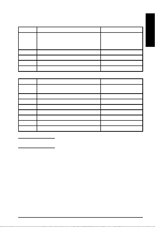
Reference
Name used
in this Guide
LJ 5P/5MP*/
6P/6MP*
LJ 5L C3941A 4K C3941-99001
LJ 5/5M*/5N C3916A/C3917A/
LJ 5Si/5SiMX*/
5Si Mopier
LJ 6L C3990A 6K C3990-90991
Model Number
C3150A/C3155A/
C3980A/C3982A
C3952A
C3166A/C3167A
C4076A/C4077A
Maximum
Pgs per
Month
12k C3980-90956
35K C3916-90984
100K C4077-90945
Service
Manual P art
Number
*Macintosh compatible.
vi
Page 8

1A
Error Codes
Error Codes
1A-1
Page 9
Error Codes
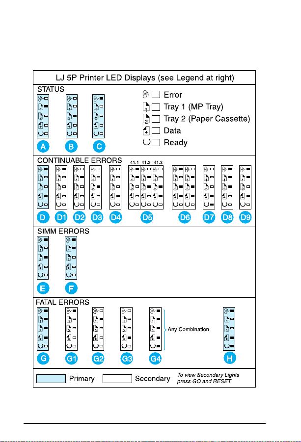
LJ 5P Printer LED Displays
For more details, refer to the page number list ed with each display letter .
If the error and data lights are both lit, simultaneously press [Go] and [Reset] to
display the Data Error pattern.
1A-2
Page 10

Error Codes
Legend (5P Display Lights)
STATUS MESSAGES
Paper Out (Tray 1)
A
(see page 1A-10)
Paper Out (Tray 2)
B
(see page 1A-10)
CONTINUABLE ERRORS
When the ERROR and DATA LEDs are on, press the Go and RESET
buttons. Follow the instructions for the secondary light patterns shown.
Primary Light Pattern (see note)
D
Error 20 (Mem Overflow)
D1
(see page 1A-13)
Error 21(Print Overrun)
D2
(see page 1A-13)
Error 22(I/O Error)
D3
(see page 1A-14)
Error 40
D4
(see page 1A-16)
SIMM ERRORS
Remove all SIMMs and power cycle the printer. Retry operation. Replace
SIMMs one at a time to locate the defective module. Refer to the Service
Manual for details.
Error 53-0 ROM Error
E
(see note above)
Error 53-1 RAM Error
F
(see note above)
FATAL ERRORS
When the DATA, TRAY2, TRAY1, and ERROR LEDs are on, press the GO and
RESET buttons. Follow the instructions for the seconda ry light patterns shown.
Primary Light Pattern (see note)
G
Error 50 Fuser
G1
(see page 1A-18)
Error 57/58 (Main Mtr)
G2
(see pages 1A-21/22)
Printer Open (page 1A-8)
C
or
No Toner Cartridge (page
1A-8)
or
Paper Jam (page 1A-11)
Error 41.1, 41.2, 41.3
D5
(see page 1A-17)
Error 68, 68.1
D6
(see page 1A-26)
Error 51 (Beam Detect)
D7
(see page 1A-18)
Error 52 (Scanner
D8
Malfunction)
(see page 1A-19)
Error 55
D9
(see page 1A-21)
Error 61.1/62.1
G3
(see page 1A-22)
All other errors
G4
(see 79 Error, pg 1A-27)
Error 63 Service Error
H
(see page 1A-22)
1
A
1A-3
Page 11
Error Codes
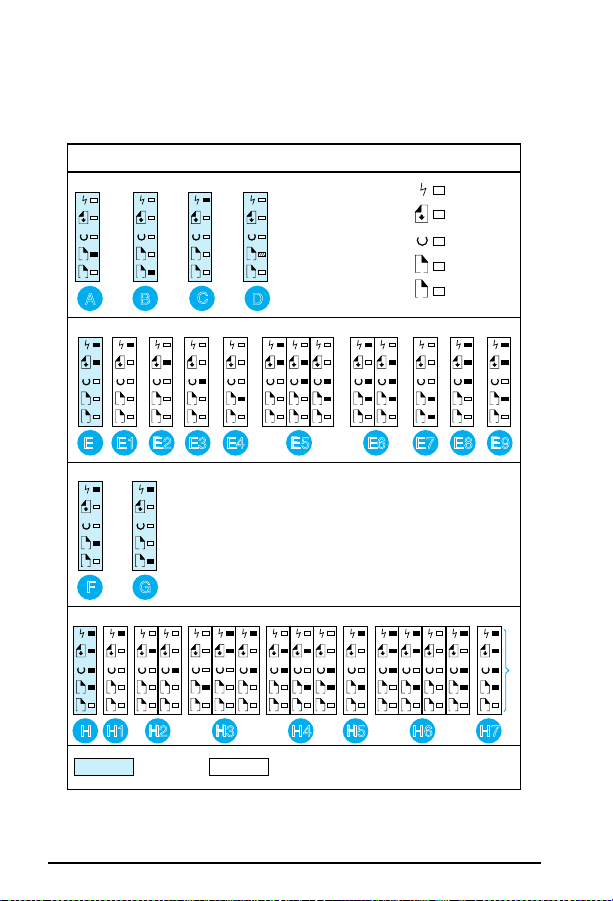
LJ 6P Printer LED Displays
For more details, refer to the page number list ed with each display letter .
If the error and data lights are both lit, simultaneously press [Go] and [Reset/Job
Cancel] to display the Data Err or pattern.
LJ 6P Printer LED Displays (see Legend at right)
STATUS
1
1
1
2
2
A
B
1
2
2
C
Tray 1
D
LED Blinking
CONTINUABLE ERRORS
1
1212121
2
E1 E2 E3 E4 E5 E7 E8 E9
E
2
121
12121212121
2
E6
SIMM ERRORS
1
1
2
2
G
F
FATAL ERRORS
11223
3
*
Error
Data
Ready
Tray 1
1
Tray 2
2
2
= Any other combination
121
H
1A-4
121
121
2
2
1
2
2
H1 H2 H3
Primary Secondary
121
2
2
121
2
2
2
1
1
H4 H5 H6 H7
To view Secondary Lights
press GO and RESET/JOB
CANCEL buttons simultaneously.
*
1
121
2
Page 12

Legend (6P Display Lights)
Error Codes
STATUS MESSAGES
Paper Out (Tray 1)
A
(see page 1A-10)
Paper Out (Tray 2)
B
(see page 1A-10)
CONTINUABLE ERRORS
When the ERROR and DATA LEDs are on, press the Go and RESET/JOB
CANCEL buttons. Follow the instructions for the secondary light patterns.
Primary Light Pattern (see note)
E
Error 20 (Mem Overflow)
E1
(see page 1A-13)
Error 21(Print Overrun)
E2
(see page 1A-13)
Error 22(I/O Error)
E3
(see page 1A-14)
Error 40
E4
(see page 1A-16)
SIMM ERRORS
Remove all SIMMs and power cycle the printer. Retry operation. Replace
SIMMs one at a time to locate the defective module. Refer to the Service
Manual for details.
Error 53-0 ROM Error
F
(see note above)
Error 53-1 RAM Error
G
(see note above)
FATAL ERRORS
When DATA, READY, TRAY1, and ERROR LEDs are on, press GO and
RESET/JOB CANCEL. Follow the instructions for the secondar y light patterns.
Primary Light Pattern (see note)
H
Error 50 Fuser
H1
(see page 1A-18)
Error 57/58 (Main Mtr)
H2
(see page 1A-21/22)
Error 61.x (x=1, 2, 3 SIMM)
H3
(see page 1A-22)
Printer Open (page 1A-8)
C
or
No Toner Cartridge (page
1A-8)
or
Paper Jam (page 1A-11)
Manual Feed (page 1A-30 )
D
Error 41.1, 41.2, 41.3
E5
(see page 1A-17)
Error 68, 68.1
E6
(see page 1A-26)
Error 51 (Beam Detect)
E7
(see page 1A-18)
Error 52 (Scanner
E8
Malfunction)
(see page 1A-19)
Error 55
E9
(see page 1A-21)
Error 62.x (x=1, 2, 3 SIMM)
H4
(see page 1A-23 )
Error 62.0
H5
(see page 1A-23 )
Error 63, 64, 64, 65
H6
(see page 1A-23 through 24)
All other errors
H7
(see pages 1A-26 through 30)
1
A
1A-5
Page 13
Error Codes
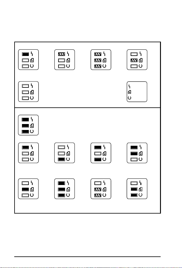
LJ 5L/6L Printer LED Displays
For more details, refer to the legend on the followi ng page, which will
refer you to recommended actions.
STATUS MESSAGES
A. Error LED is on.
*Unclearable error.
B. Error LED is
blinking.
C. All LEDs are
blinking.
D. Data LED is
blinking.
Error
Data
Ready
E. All LEDs are off. LED Legend
ERROR AND SERVICE MESSAGES
A. Error LED is on.
*Unclearable error.
E. Data LED is on. F. All LEDs are on. G. Data and
When all lights are on, there is a Service Error. Press and hold
the Front Panel Button to display the LED error code pattern.
The code will be shown only while the button is pressed. The
following pictures show the possible LED error patterns.
B. Ready LED isonC. Error an d
Ready LEDs are
on.
Ready LEDs are
blinking.
D. Error and Data
LEDs are on.
H. Formatter Error
* An unclearable error is not strictly a service message. It will appear without
all three lights being displayed first. See letter A in Status and Error sections.
1A-6
Page 14
Error Codes
5L LED Patterns for St at us and Error Messages
Status Messages
Item Description Recommended Action
A Paper Out
Door Open
No EP Cartridge
Paper Jam
B Memory Error See page 1A-13
C Incompatible Memory Card See page 1A-21
D Manual Feed See page 1A-29
E Sleep Mode See page 1A-28
Error an d Service Messages
Item Description Recommended Action
A Unclearable Error
Engine Error
B ROM/RAM Error See page 1A-20
C Fuser Error See page 1A-18
D Beam Error See page 1A-18
E Scanner Error See page 1A-19
F Formatter Error See page 1A-23
G F irmware Error See page 1A-29
H Formatter Error See page 1A-2223
See page 1A-10
See page 1A-8
See page 1A-8
See page 1A-11
See page 1A-30
See page 1A-16
1
A
Note
Before troubleshooting any Service Error, power
cycle the printer to see if the error persists.
1A-7
Page 15

Error Codes Clear Jam Staple
Optional Output Bin X
Error Code Tables (LJ 5 series and newer)
Clear Jam Staple
Option al Ou tput Bin X
5 Si Mopier
1. Clear the jam.
2. Check the staple cartridge.
3. Check stapler and cabling.
4. Check Stapling Unit Control PCA.
5. Replace the entire Stapling Unit as required.
Close P rinter Cove r/Pr inter Open
All Printers
1. Printer Door open.
Check that toner cart ridge is full y seated and tha t the covers are fir mly
clos ed.
2. Defective DC Power Supply.
3. Defective DC Controller.
4. Actuator or tab missing or broken.
5. Defective Paper Control PCA.
Install Toner Cartridge/No Cartridge
All Printers
1. Reseat or install new toner cartridge.
2. Dirty or defective High Voltage contacts.
3. Defective High Voltage Power Supply.
5
1. Defective DC Controller.
Install T r ay 2
5
1. Lower Cassette (T ray 3) selected and printer detected Paper Cassette
(Tray 2) not installed.
Install or reseat PC (Tray 2), which is the paper guide for the LC (Tray 3).
2. Improperly fitted PC.
Firmly rese at t he PC.
1A-8
Page 16

Error Codes Out of Staples Optional Output X
Out of Staples Optional Output X
5Si Mopier
1. Re pla ce th e st apl e ca rtri dge .
2. If message continues after cartrige has been replaced, check stapler,
T op Cover Assembly, and cabling.
3. Check Stapling Unit Control PCA.
4. Replace the entire Stapling Unit as required.
Output Operation Condition x.yy
5Si Mopier
x= output device number
yy=condition code
For the Multi-Bin Mailbox:
01 = Face-Up Tray not installed
Note: Refer to the 2000-Sheet Input Unit and Multi-Bin Mailbox/Mailbox
with Stapler T rouble shooting Chec ks for more info rmation.
Remove Paper Jam
5
1. See 13 Paper Jam — All Printers
2. Rear Door open.
3. Broken or missing Cassette Paper Out Sensor Flag.
4. 500 sheet lower cassette not properly adjusted (see Service Note
C2001A-01A)
Adjust tr ay follo wing ser vice no te.
5. Check transfer roller to ensure it is seated properly.
6. Bad Input Sensor (PS1), Fuser Exit Sernosr (PS3), or with jams from
the MP T ra y (T ray 1), bad Pape r En d Se nsor (PS5 ).
1
A
Staple Limit Reached
5Si Mopier
1. Send only print jobs of 20 pages or less to the stapler.
Stapler Align Error
5Si Mopier
1. Remove the paper from the stapler and resend the job.
1A-9
Page 17

Error Codes Stapler Malfunction
Stapler Malfunction
5Si Mopier
1. Clear the stapler jam and resend the job.
Stapler Supply Out
5Si Mopier
1. Load a new staple cartridge.
Toner Low
5/5Si
1. Toner is uneven in cartridge.
2. Malfunctioning Toner Cartridge contact points.
3. Defective HV Power Suppl y.
Tray x Emp ty/x L oad/Pap er Out
ALL Printers
1. Paper or Paper T ray empty or not seated correctly.
2. Sensor Arm stuck or broken.
3. Defective tray size sensing or configuration.
V erify tra y tabs and swit ches at right re ar (or right front) of tray slot o r
configure tray from control panel.
4. Defective Paper Control/Sensor PCA.
W armin g Up
5/5Si
1. Separate all accessories.
2. Power cycle the printer.
3. Defective formatter.
4. Defective DC Controller.
5. Defective power supply.
1A-10
Page 18

Error Codes 13 Paper Jam/Remove Paper Jam
13 Pape r J am/Rem ove Paper Jam
ALL Printers
1. Out of spec media.
2. Dirty or obstructed paper path.
Clean paper path components, check transfer roller is seated properly.
3. Worn Pickup (or other) Rollers and/or Separation Pad.
4. Wrong length paper or incorrect software paper size selected.
5. Defective Exit Sensor or flag.
6. Defective Input (paper out) Sensor doesn’t sense paper out.
7. Paper Casse ttes not c orr ectly load ed.
8. Bad solenoid operation.
V erify proper solenoid operation and replace as necessary.
9. Bad gear(s) or gears not meshing in drive train.
Repl ace bad gear s, ch eck tone r car tri dge gears for da mage .
10. Bad Main Motor or Drive Circuit.
11. Bad Delivery Mechanism or coupler gear to main drive.
12. Bad Main Motor Drive Circuitry.
13. Defective DC Controller.
5P/6P
1. Paper fragment under oblique rollers (top or front).
Remove rollers and clear out paper.
5L/5P/6P
1. If all flags move properly and connectors are seated and the error
persists, replace the DC Conroller .
13.x Pa per J am
5 Si
Note: When troubleshooting the LJ 5 Si, always troubleshoot the error log
message. See the LJ 5 Si Service Manual for detailed error log information.
X=Locat ion o f jam
=Non-specific jam
0
=Paper feed/paper late jam—paper late arriving at PS 2; lo cated in
1
paper pickup unit. Inspect paper path. Verify flag movement.
=Paper feed 2 paper late jam—paper late arriving at PS 2, which is the
2
registration photo sensor. Remove toner and lift up green lever to access
sensor flag. Verify flag movement.
=Fuser output paper late jam—paper late arriving at PS 1403, which is
3
in th e fusin g ass embl y . V e rif y flag mov eme nt.
1
A
1A-11
Page 19

Error Codes 18 MIO Not Ready
4=Fuser output paper stopped jam
5, 6=Duplex module paper jam. PS 1402 face-down delivery photo
sensor is located in the face-down delivery assembly . Inspect diverter
drive assembly. V erify paper path from fuser to top of face-down bin is
clear and fl ag mov es f reely.
7-10= Duplex module paper jam. Paper is diverted to the duplex
module after leaving the fusing assembly. Paper is turned around in the
duplexer and refed into the printer’s paper path. Reseat the duplex
module. If problems persist, replace the complete duplex assembly.
11=External input device paper jam
If the control panel displays a 13.1 1 Paper Jam message, the printer will
list additional error codes in the error log. These can be printed or viewed.
2000 Sheet Input Tray Paper Jam Error is related to the first device in the
C-Link daisy chain. In the supported configuration this device should be
the 2000-sheet high-capacity tray. Ver ify that Tr ay 4 lifts to its feed
position. Inspect flags in vertical transfer door.
12=External output device paper jam
If the control panel displays a 13.12 Paper Jam message, the printer will
list additional error code s in the error log. These can be printed or viewed.
Multi-Bin Mailbox/stapl er paper jam. Error is related to th e second or
third device on the C-Link daisy chain. In the supported configuration,
this second device should be the Multi-Bin Mailbox. Verify that all bins
are in position and the “scan bar” is complete. V erif y that the Multi-Bin
Mailbox completes its power up sequence. In the supported
configuration, the stapler is the third device in the C-Link daisy chain.
V erify the st apler completes its power- up sequence.
13=Fuser accordion jam. Inspect paper path before and after fuser.
14=Printer could not auto eject paper. Inspect entire paper path for
paper or debris.
18 MIO Not Rea dy
5/5Si
1. Printer is not connect ed to active LAN.
Connect printer to LAN or terminate connection using a BNC
T-Connector with two 50 Ohm resistors.
2. MIO card is misaligned or defective.
Reseat or replace MIO card.
1A-12
Page 20

Error Codes 18 MIO Init
18 MI O Init
5/5Si
1. Error message remains after 5 minutes.
Check network card or host.
20 Error/Mem Overflow
ALL Printers
1. Large print job exceeding memory capacity.
V erify SIMMs seate d. Add mem ory , re move soft fonts, d ecrease
resolution, or simplify print job. Adjust image adapt and page protect
settings, if available.
5
1. Too much data or data too complex.
Turn image adapt and page protect to ON or AUTO (can be set within the
Remote C ontrol Panel). Press [GO] to resume print ing.
5L/6L
1. Set Enhanced I/O to Auto Mode (PCL mode).
Resend print job. If Auto-Cont inue variable is on with in PJL, the printer
will continue to print after 10 seconds. If off, press the Front Panel Button
to continue printing.
21 Error/Print Overrun
ALL Printers
1. Too complex print job.
Simplify print job or add memory.
5Si
1. Too complex print job.
Enable Page Protect from Cont rol Panel and from softw are (may require
additional memory).
5
1. Too much data or data too complex.
Turn i mage adapt and page protect to ON or AUTO (c an be set wi thi n the
Remote Control Panel). Press [GO] to resu me printing.
5P/5L/6P/6L
1. Use remote control panel to turn Page Protect to Auto or On.
1
A
1A-13
Page 21

Error Codes 22 Error/ I/O Config Error/Par I/O Error / MIO Error
22 Error/ I/O Config Error/Par I/O Error / MIO
Error
ALL Printers
1. I/O config for the computer or printer is incorrect.
Refer to manual for proper configuration.
2. Wrong or damaged I/O Cable.
Replace I/O cable with specified cable (IEEE1284).
3. Computer is powered off.
Power computer on.
4. Damaged printer I/O port.
Replace I/O PCA or Formatter .
5P , 5, 6P
1. The computer and printer are not communicating because of improper
signal protocols. Indicates a loose cable connection or a bad or poor
quality cable.
Reseat the cable and make sure you are using a high-quality cable (IEEE
1284).
5Si
1. Using a non-HP MIO device.
Repl ac e w it h a H P M IO d e vi ce .
23 I/O Not Rea dy
ALL Printers
1. I/O card is unable to accept data or is not connected to the network.
Check I/O Ca rd s eating an d rep lace if nece ssary.
24 Job Memory Full
ALL Printers
1. Complex printer job.
Add memory or simplify print job.
25 XXXMem Full
ALL Printers
1. Complex printer job.
Add memory or simplify print job.
1A-14
Page 22

Error Codes 30 PS Error 16
30 PS Er ror 16
ALL Printers
1. An I/O time out or prom pt for use r in teraction (e.g., man ual feed) has
been exceeded.
Check I/O connections and whether media requests are being made.
30 PS Er ror 22 or 25
ALL Printers
1. Unexpected PostScript firmware error .
Replace PostScript SIMM.
30 PS Error XX (All Other)
ALL Printers
1. PCL file being sent to printer while in PostScrip t mode or bad
PostScript file or application error.
Check configuration, applicat ion, and print fil es.
30.1.1 Disk Failure
5 Si
1. Optional di sk failed self tes t.
Press [ Select] to continue.
40 Err or (data trans fer e rro r)
ALL Printers
1. Computer and printer may be set to different baud rates.
Refer to manual to reset baud rates.
2. Computer is powered off.
Power computer on.
3. Unseated or defective MIO card.
Remove, reseat , or repla ce MIO card.
4. Indicates an abnormal connection break occurred while transferring
data from the computer.
Press [Continue] or [GO] on the printe r to clear the error message.
1
A
1A-15
Page 23

Error Codes 40.x MIO Error
40.x MI O Err or
5Si
1. Add normal connection break in the specified MIO card occured.
If x=1; HP MIO port 1 (upper slot)
If x=2; HP MIO port 2 (lower slot)
Press [Select] to continue or power cycl e the printer . If the error pers ists,
repl ace MI O card .
41 Error (temporary print engine failure)
ALL Printers
1. Momentary error.
Reset by pressing the [Continue] or [Go] key.
5P/6P
1. A temporary error occurred while printing.
This error most commonly occurs when the printer picks two sheets of
paper at once. The page containing the error is reprinted automatically.
Remove the page from the output tray and press [GO] on the printer.
5L/6L
1. Temporary Error
Power cycle the printer . If the error persists, reseat the Formatter to the
DC Controll er PCA.
2. Engine Error
Replace the Formatte r PCA. If the error pers ists, replace the DC
Controller PCA.
41.x Error
5, 5S i
1. If x= 1; Defective connections.
Reseat J205, J206, J207 and Laser/Scanner connections.
2. If x=2; Beam Detect malfuction.
Reseat connectors, including laser scanning assembly.
3. If x=3; Paper size selection does not match installed paper or paper
multifeed.
Check for paper jams, multifeeds, or missfeeds.
Insert correct siz e paper .
One of the cassettes is overfull or improperly adjusted.
4. If x=4; Sync error.
Reseat DC Controller and Formatter connections.
1A-16
Page 24

Error Codes 50 Error / 50 Service (Fuser Malfunction)
5. If x=5; Video sync or undetermined error.
Reseat DC Controller and Formatter connections.
50 Error / 50 Service (Fuser Malfunction)
ALL Printers
1. Temporary error.
Power off for 20 mi nutes to clear tem porary 50 Error .
2. Low/unstable power (e.g. brownout).
Locate/verify stable power source.
5
1. Defective Fuser or Pwer Supply.
Replace Fuser followed by P ower Supply if probem persists.
2. Temporary error.
Short C202 (LJ 4) or C205 (LJ 4 Plus) on the DC Controller to bypass
Error 50 time delay .
5P/6P
1. Defective Fuser.
2. Defective DC Controller.
5L/6L
1. Check the r esistan ce betw een pins 1 and 2 from co nnector J102 of the D C
Controller and the Thermistor .
If no r esist ance, rep lace t he heati ng el emen t. If resis tan ce is c orr ect,
repl ace th e DC C ontr ol ler .
50.x Fuser Error
5Si
1. Fuser malfunction.
If x=1; Fuser low t emperature fa ilure.
If x=2; W arm up fa ilure.
If x=3; Over temperature failure.
If x=4; Bad fuser.
Power printer off for 20 mintues, then back on.
V erify th e fuser is inst alled correct ly and fully se ated.
Reseat or repla ce the fuser ca ble assembly .
1
A
1A-17
Page 25

Error Codes 51 Error (loss of beam detect)
51 Error (loss of beam detect)
5
1. Faulty Laser/Scanner Cable Connectors.
2. Defective Laser/Scanner Assembly.
5P , 5L,6P , 6L
1. Temporary error.
Power-cycle the printer .
2. Laser/Scanner Assembly not seated.
3. Defective Laser/Scanner Assembly.
Replace the Laser/Sc anner Assembly (or cable —5L only).
4. Defective DC Controller PCA (5L, 5SI only)
51.x E rror
5Si
1. Laser subsystem problem.
If x=1; Beam detect malfunction.
If x=2; Laser malfunction.
Press [Select] to resume operation. (If AU T OCONT=ON)
If error persists:
Check cable from DC C ontr ol ler t o la ser scan ner .
Repl ace la ser scanne r ass embl y .
Repl ace DC C ont roll er P CA.
52 Error (incorrect scanner speed)
5
1. Faulty Laser/Scanner Cable.
2. Defective Laser/Scanner Assembly.
5P , 5L, 6P , 6L
1. Temporary error.
Power-cycle the printer .
2. Improperly fitted Scanning Assembly.
3. Scanner cable problem.
4. Defective Laser/Scanner Assembly.
5. Defective DC Controller PCA.
1A-18
Page 26
52.x E rror
5Si
1. Scanner subsystem problem.
If x=1; Scanner startup failure.
If x=2; Scanner rotatio n failure.
Switch the printer off and back on.
If the error conti nues:
Check cable from DC Control ler to lase r scanner assem bly .
Repl ace la ser scanne r ass embl y .
Repl ace DC C ont roll er P CA.
53.XY . ZZ Error
5/5Si/5P/6P
1. SIMM malfunction.
T able 1-1 53.XY .ZZ Error fo r 5, 5Si
X (Hardware Type)
x=0, ROM 0=Unsupported memory
x=1, RAM
x=2, Flash
Y (Hardware Device)
y=0 Internal mem.
(Formatter PCA)
y=1 SIMM Slot 1
y=2 SIMM Slot 2
y=3 SIMM Slot 3
y=4 SIMM Slot 4
ZZ (Error Nu mber)
1=Unrecognized memory
2=Unsupported mem. size
3=Failed RAM test
4=Exceeded max RAM size
5=Exceeded max ROM size
6=Invalid SIMM speed
7=SIMM report ing info. incorrectly
8=SIMM RAM parity error
9=SIMM ROM mapped to an unsupported address
10=SIMM address conflict
11=ROM out of bounds
12=Could not make temporary mapping
Error Codes 52.x Error
1
A
5L/6L
1. An error has been found in the RAM or ROM.
Power-cycle the printer .
2. Defective or incompatible memory card.
Power off the printer, remove any additional memory, then power back
on. If the message cle ars replace th e memory card.
3. Defective Formatter PCA.
5, 5P , 5Si, 6P
1. SIMM malfunction.
V erify S IMM board is inst alled correct ly .
Repl ace th e SIM M tha t cau sed th e err or .
1A-19
Page 27

Error Codes 54 Error
54 Error
5Si
1. Defective Duplexer.
Repl ace dup le xer .
55 Error (internal communication pr oblem)
ALL Printers
1. Loose/bad cable.
2. Defective DC Controller PCA.
3. Defective Formatter PCA.
4. Defective Paper Input PCA.
5. Defective Main Motor.
56.x Error
5Si
1. Invalid input source or output destination has been selected.
If x=1; invalid input source.
If x=2; invalid output destination.
Check input and output devices.
Reselect a valid device.
57 Error
5L/6L
1. Incompatible memory card.
Remove card and replace it with a 1, 2, 4, or 8 MB, 5V , 70 nsec. or faster
card.
5, 5P , 6P
1. Main motor not fuctioning properly.
Check for any binding in motor or gear train. Check connection to DC
Controller , then repl ace main motor or DC Con troller as nece ssary .
1A-20
Page 28

Error Codes 57.x Service
57.x Ser vice
5Si
1. Faulty Fan Mot or x.
Check Fan number x, main or duplexor fan, and replace if necessary.
5
1. Main Motor Fa ilure .
58 Servic e
5, 5P , 6P
1. Improperly fitted Fan Cable.
Check/reseat Fan Cable.
2. Defective Fan.
58.x Printer Error
5Si
1. Tray lifter malfunction.
If x=1; Tray 2 lifter malfunction.
If x=2; Tray 3 lifter malfunction.
If x=3; Tray 1 lifter malfunction.
If x=4; Tray 4 lifter malfunction.
Press [ Sele ct ] to co nt inue .
Repair or replace tray/lif ter .
59.x Printer Error
5Si
1. Main motor malfuncti on.
If x=1; Main motor startu p failure.
If x=2; Main motor rot ation failure .
Switch the printer off, then back on.
If the message persists:
Check cabling between the main motor and DC Controller.
Repl ace th e main mot or .
Repl ace th e DC C ontr ol ler .
1
A
1A-21
Page 29

Error Codes 61.x Service
61.x Ser vice
ALL Printers
1. Improperly fitted SIMM in slot x.
2. Defective SIMM in slot x.
3. Defective Formatter.
Note: If x=0, SIMM slot counldnot be determined.
62.x Service / Printer Error
ALL Printers
1. Improperly fitted SIMMs or Font Cartridge.
2. Defective Internal Memory. (x=0)
Repl ace For mat ter PCA.
3. Defective SIMM Slot X.
63 Servic e
5, 5P , 6P
1. Defective Formatter PCA.
Replace Formatter PC A.
5L/6L
1. Defective Formatter PCA.
Power cycle the printer. Disconnect the parallel I/O cable and run a self
test. If the error persists , replace the Format ter PCA.
64 Servic e / Printe r Err or
ALL Printers
1. Defective Formatter PCA.
5Si
1. Defective DC Controller PCA.
65 Servic e
All Printers
1. Defective Formatter PCA.
1A-22
Page 30

Error Codes 65 Printer Error
65 Printer Error
5, 5Si, 5P , 6P
1. Indicates a dynamic RAM error .
Switch the printer off, then back on.
If the message persists, replace the Formatte r PCA.
66.x.yy D evice Error
5Si
If the control panel displays a 66.x.yy Device Error message, the printer
will list addition al error codes in the error log . These can be printed or
viewed .
Indicates a paper handling error. Printer is unable to communicate with
the external paper handling PCA. Verify C-Link cables are installed
correctly . Print the PCL Configu ration Page and note which installed
devices are not present on the Configuration Page.
x=paper handling device
0=external paper handling PCA (EPH)
1=first device attached to EPH
2=second device attached to EPH
3=third device attached to EPH
4=fourth device attached to EPH
5=fifth device attached to EPH
Switch the printer and paper handling devices off, then on. If the message
persists:
yy=paper handling device error code
1
A
If yy=1-22, 24:
Check cabling between the printer and the device.
Check the me chan ical int erf ace bet wee n the print er a nd th e devi ce.
Replace the external paper handling PCA.
If yy=23:
Check cabling and mechanical interface between printer and device.
Replace the external paper handling PCA.
Repeat steps 1 and 2 to isolate defective device.
Repai r or r epl ace d efect iv e devi ce.
If yy=31:
Printer not supported by paper handling device 1.
1A-23
Page 31

Error Codes 67 Service / Printer Error
If yy=32:
Printer not supported by paper handling device 2.
If yy=33:
Printer not supported by paper handling device 3.
If yy=34:
Printer not supported by paper handling device 4.
If yy=35:
Printer not supported by paper handling device 5.
For error codes 31-35: Verify that the device is supported.
If device is supported, follow steps under yy=23.
If yy=41:
Device 1 reports invalid configuration.
If yy=42:
Device 2 reports invalid configuration.
If yy=43:
Device 3 reports invalid configuration.
If yy=44:
Device 4 reports invalid configuration.
If yy=45:
Device 5 reports invalid configuration.
For error codes 41-4 5:
V erify proper configuration for device.
If configuration is correct, follow steps under yy=23.
67 Servic e / Printe r Err or
5
1. Defective Formatter PCA.
Reseat any accesso ries. If erro r persists, re place Forma tter PCA.
5Si
1. FRU’s not ins talled pro perly .
Reinstall FRU’ s.
1A-24
Page 32

Error Codes 68 Error / Service
68 Error / Service
ALL Printers
1. Defective Formatter PCA.
5, 5P , 5 Si, 6P
1. (68 Error) - error in NVRAM.
Check Control Panel setting s. Replace Formatter if p roblem persists.
5, 5S i
1. (68 SERVICE) -NVRAM full.
Cycle printer power . If probl em persists, perform NVRAM initia lization
by holding down the [Item] (or {Job Cancel] on the LJ 5) while powering
on the printer. All Control Panel settings (including Service Mode
settings) will require resetting following this procedure.
5P/6P
1. (68 SERVICE) -NVRAM full.
Perform a NVRAM initialization by holdin g down the RESET button for
more than 20 seconds while powering on the printer.
69 Servic e
ALL Printers
1. Defective I/O PCA.
Remove optional I/O PCA, then re-test.
2. Defective Formatter PCA.
Replace Formatter PC A.
70-71 E rr or
ALL Printers
1. Personality cartridge in SIMM slot incompatible.
5Si
1. Faulty MIO cards.
1
A
72 Servic e
ALL Printers
1. Defective Formatter PCA.
Replace Formatter PC A.
1A-25
Page 33

Error Codes 79 Service
79 Servic e
ALL Printers
1. Software/drivers, Memory PCA’ s, Font-Macro-Personality,
Cartridges, optional I/O cards. Defective toner cartridge.
Remove any accessories (font cartridges, memory PCAs SIMMs etc.)
plugged in to the Formatter and reprint file. If problem persists verify
proper setup with application vendor.
2. Defective Formatter PCA.
5 SI
Unrecoverable firmware error occurred.
1. Cycle power .
2. Reseat or replace the interface cable and cycle power.
3. Remove the SIMMs one at a time and cycle power .
4. Remove the MIO Card(s) one at a time and cycle power.
5. T ry using the pa rallel inte rface, if possib le.
6. With the MIO cards out of the printer , perform a COLD RESET.
7. If error continues, replace the formatter. Write down the page count
and serial number.
80 MIO Failu re
ALL Printers
1. Improper MIO connection.
Inspect pins on formatter MIO connection.
2. Defective MIO Card.
3. Defective Formatter PCA.
81 Error
ALL Printers
1. Defective Formatter PCA
89 PostScript ROM Failure
ALL Printers (except 5L and 6L)
1. Bent / broken pins on PostScript ROMs.
Inspect PostScript ROMs/SIMM for bent or broken pins.
2. Improperly located ROMs/SIMM.
Check that ROMs/ SI MM are i n cor rect loc ati on and ori ent ati on.
1A-26
Page 34

Error Codes All LEDs off (blank display).
3. Temporary error.
Cycle P ower .
4. Defective PostScript ROMs/SIMM.
All LEDs off (blank display).
5L/6L
1. Printer is in Sleep Mode.
Press Front Panel Button or open the EP Door
2. No power is supplied to printer.
Check power cord connections and power source.
3. Determine if print engine is functional.
Print an engine test; if successful, replace Formatter PCA.
4. Defective Contr ol Panel PCA cabl e.
5. Chec k f u ses o n DC C ont ro ll er.
6. Defective Formatter PCA.
7. Defective DC Controller.
All LEDs on (without pressing the front panel
button).
5L/6L
1. This is a service error .
Press down on the front panel button to display the error LED code. This
code will be shown only while the button is pressed.
2. All LEDs remain on while pressing the front panel button.
Cycle power . If error pers ists, replace the formatter .
Blank Display
ALL Printers
1. No power.
Check AC and DC volt ages .
2. Defective display panel, related cabling, or drive circuitry.
Check input voltages which illuminate the Display Panel.
3. Faulty display, cable, Formatter , or DC Controller.
1
A
1A-27
Page 35

Error Codes Data and Ready LEDs are blinking
Data an d Ready L EDs are blinki ng
5L/6L
1. Firmware Error
Note the LED pattern, Bi-Tronics error code, printer condition, data sent,
and any other information that may help isolate the error . Contact
HP technical support with this information.
Data LED is blinking
5L/6L
1. The printer is set to manual feed.
Insert paper into the manual feed slot. Ensure correct paper is loaded in
the printer . Press and release the Front Panel Button. If manual feed is
not desired, turn off the setting in the software application.
2. Printer is stuck on manual fe ed
Press the front panel button to override the manual feed request and to
feed paper from the paper casset te.
3. Defective Input Paper Sensor (PS1) or defective Front Oblique Roller
Assemb ly .
Replace PS1 or Fro nt Obli que Roller Ass embly .
Displa y Is All Bloc k Chara cters
ALL Printers
1. Display cable defective or disconnected.
Reseat or replace Display Panel cable.
2. Defective C ontro l Pa nel.
3. Defective Formatter PCA.
Check and re plac e as ne ede d.
Error LED is on co ntinuously
5L, 6L
1. Power cycle the printer.
2. Bad connection between formatter and AC Controller.
3. Defective formatter.
4. Defective AC controller.
1A-28
Page 36

Error Codes Tray 1 LED is Blinking
T ray 1 LED is Blink ing
6P
1. The printer is set to manual feed. Insert paper into Tray 1 and press the
GO button.
1
A
1A-29
Page 37

Error Codes Tray 1 LED is Blinking
1A-30
Page 38

2A
Service Mode
Service Mode
2A - 1
Page 39

Service Mode
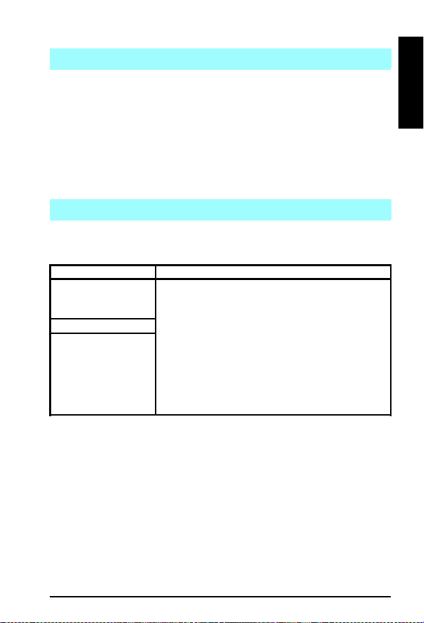
The following can be executed while in the Service Mode
Print a Service Mode Self Test.
Verify the Page Count. (The page count is also displayed on the
standard self test.)
Set the Page Count.
Set the Cold Reset Default (LJ 5). This sets the factory default paper
size. Use when replacing non-U.S. Formatters.
Set the Diagnostic Function (LJ 5). On/Off (for software developers
use only).
Demo Page=On/Off (LJ 5). Removes the Demo Page option from the
self test menu.
The following illustrates the procedure used to initiate Service Mode.
A
PowerOff Printer
Hold Keys Down Simultaneously While Powering Printer On Press Keys Sequentially
B
B
B
LJ 5
Menu + Value +
(Power)
D
LJ5is now in Servicemode.
EC
LJ 5Si
LJ5Si
Mopier
Figure 2-1
Items + Select(Power)
Notes:
Service Mode not available on the LJ 5L.
Service Mode in the LJ 5P can only be done via software (PJL commands).
Please consult the Service Manual.
Howto access Service Mode
1. Power off theprinter (A).
2. Press thetwoor threekeys referenced (B) simultaneously, whilepoweringtheprinteron (C).
3. Press key (D) if required.
4. Press key (E) if required.
After a few seconds the printer's display should say "Service Mode".
6L, 5P, 6P
,
Accessing Service Mode
LJ5Si is now in
Servicemode.
EC
EC
There is no Service Mode or NVRAM on the LaserJet 5L, 6L, 5P , or 6P
printers. These page counts are retained only while plugged in; page count is
lost when the printer is unplugged.
2A - 2
Page 40

Service Mode
Setting the Page Count
(except on the LJ 5L, 5P, 6P, 6L)
The page count is stored in the printer’s Non-Volatile Memory . If it becomes
necessary to replace the Formatter PCA, the page count should be reset to the
printer’s original page count to reflect the age of the print engine. Use the
following procedure to set the page count.
1 When 00 S MODE
to modify the page count.
2 PA GES=XXXXXX will be displayed.
currently stored in the printer’s Non-V ola tile Memory . The underlined
character denotes the cursor position.
3 Press [+] (or [AL T] [- ]) to scroll unti l the correct valu e is displayed for the
underlined digit.
4 Press the [ENTER] key to select the corre ct value. The cursor will
automatically move one place to the right.
5 Set each digit in the same manner. When the last digit’ s value has been
selected, the display will return to 00 SMODE or SERVI CE MODE.
6 Press the [ON LINE] key to exit Service Mode.
or SERVI CE MODE is displayed, click the [MENU] key
XXXXXX represents the page count
Setting the Cold Reset Default Paper Size
The initial default paper size f or the Formatter PCAs in Eur ope is A4. When
replacing Formatte rs whose default is set for A 4, (Europe an Formatters), s et the
customization variable to A4. When the cu stomization variable is set to A4, t he
Cold Reset procedure can not reset the paper size to Letter . T o set th e
custom iz ati on var iab le:
(LJ 5 Only)
1 Turn off the printer.
2 Hold the Go key down while powering ON the printer.
3 The message FACTORY DEFAULT S BEI NG RES T ORE D is displayed. The
Cold Reset does not take effect u ntil the REA D Y message is displayed.
4 When the REA DY message is displayed, the default settings have been
returned to the factory defaults and the printer is ready to accept new
settings.
2
A
2A - 3
Page 41

Service Mode
(LJ 5Si)
1 Enter the Service Mode as described previously.
2 Press [MENUS] to acce ss the Service Menu.
3 Press [ITEMS] to step through the menu until COLD RESET
PAPER=LET T ER* is displayed.
4 Press [+] to toggle between Letter and A4 paper.
5 Press [SELECT] to activate your choic e.
6 Press [ON LINE] to exit Service Mode.
7 Perf orm a C old Reset to a cti vate new ch oi ce.
2A - 4
Page 42

3A
Power Supply Chec ks
Power Supply
Checks
3A - 1
Page 43

Power Supply Checks
LaserJet 5
Pin 1
3
2
45
6
TB 201
Figure 3A - 3
DC Power Supply Checks (LJ 5) TB201 on DC Controller
The operating voltages of the LJ 5 can be verified by:
1 Listening for the exhaust fan. A rotating fan indicates that the +5V dc and
the +24A V dc are present. (The fan runs on +24A V dc.)
2 Listen for the Main Motor . If the Main Motor runs, +24B V dc is enabled.
The 24A V dc must be present.
TB201
Voltage Color Pin Number
+5 V dc Brown 1,2
+24 V dc Red 3
Ground Blue 4, 5, 6
3A - 2
Page 44

Power Supply Chec ks
LaserJet 5P
The DC Power Supply circuitry, located on the DC Controller PCA, generates
+5V dc, and +12V dc, used as follows:
+5V dc:
Formatter PCA
Photosensors
DC Controller Circuitry
Laser/Scanner Assembly
+12V dc AS (after switch):
High Voltage Power Supply
Main Motor
+12V dc BS (before switch):
Solenoids
Fan (Through Laser/Scanner Assembly)
Fusing
heater
3
A
VBS=Voltage Before Switch
VAS=Voltage After Switch
Figure 3A - 4
LJ 5P Power System Block Diagram
3A - 3
Page 45

Power Supply Checks
LaserJet 5L/6L
The DC Controller PCA c oordinates all print e ngine activities, drives the laser,
and coordinates print data from the Formatter PCA with the image formation
process. The DC Controller also includes both ac and dc power supply and
distribution circuitry. The DC Controller controls the following systems and
functions:
Print Engine Control
Laser and Scanner Dri ve
Paper Motion Photosensors (Paper Out, Paper Registratio n, and Paper
Exit Sensors)
Motor
Power System
AC Power Distribution
DC Power Distribution
Overcurrent/Undervoltage Protection
SleepMode
High Voltage Power Distribution
AC Driver
Supply
+5V
+12V
Low-Voltage
Figure 3-5
3A - 4
DC Controller Loads
Page 46

Power Supply Chec ks
LaserJet 5Si
The AC and DC ppower supply circuits are contained in the Low V oltage
Power Supply (L VPS). Th e high voltages requir ed for image form ation are
generated by the High Voltage Power Supply (HVPS). The Low V oltage Power
Supply and Distribution System is illustrated below.
3
A
Figure 3-6
Low Voltage Power Distribution System
3A - 5
Page 47

Power Supply Checks
3A - 6
Page 48

4A
I/O Information
I/O Information
4A - 1
Page 49

I/O Information
Bidirectional Parallel Interface
(LJ 5, 5P, 5L, 5Si, 6P, 6L)
The Bidirectional parallel interface (IEEE-1284 Compliant) is compatible with
Centronics parallel inte rfaces. T o take advantage of its enhanced capabilit ies such as bidirectional communicati on - the following must be provide d:
Software application support for these features.
An IEEE-1284 compliant parallel cable with the correct pin
configuration (see below).
HP helped develop the IEEE-1284 sta ndard and is one of the first companies to
introduce products that are compliant with it. HP offers four IEEE-1284
compl ian t par all el c able s, sh own b elow :
IEEE-1284 Compliant Parallel Cable s
Part Number Length Connector Type
C2950A 2 meters Host A to printer B (large) connector
C2951A 3 meters Host A to printer B (large) connector
C2946A 3 meters Host A to printer C (small) connector
C2947A 10 meters Host A to printer C (small) connector
4A - 2
Page 50

I/O Information
RS-232-C/RS-422-A Serial Interface
Common Serial I/O Cables
The following serial cabl ing schematics are typical of IBM (AT/XT) and
compatible personal computers using the standard (9/25) pin serial RS-232C
interface.
Printer
(Male connector)
Chassis Ground
TD
RD
DSR
Sig Gnd
DTR
1
2
3
6
7
20
(Pins not shown are not used)
Computer
(Female Connector)
1 Chassis Ground
3RD
2TD
20 DTR
7 Sig Gnd
5 Clear to Send
6 DSR
Printer
(Male connector)
TD
RD
DSR
Sig Gnd
DTR
2
3
6
7
20
(Pins not shown are not used)
25 to 9-Pin Serial Adapter (P/N C2809A)
The pin-outs for the adapter are shown below:
Computer
(Female Connector)
2RD
3TD
4 DTR
5 Sig Gnd
6 DSR
8 Clear to Send
4
A
4A - 3
Page 51

I/O Information
Serial I/O Specifications
Handshaking Protocol
Data Format
Parity
Support e d Baud Rates
*LJ 5 & Newer: Supports to 57,600 Baud
RS-232-C: Xon/Xoff (software) and Data
Terminal Ready (hardware)
RS-422-A: Xon/Xoff (software) only
The signal logic or “sense” of the DTR line is
switchable to either active HIGH (the factory
default) or active LOW from the printer’s control
panel.
Asynchronous, with one start bit, eight data bits,
and one stop bit
Not used
300, 600, 1200, 2400, 4800, 9600, 19200,
57600*
Maximum I/O Cable Lengths
Serial RS-232
Parallel (non-IEEE 1284)
RS-422
50 feet (15 meters)
4000 feet (1,200 meters)
10 feet (3 meters)
Configuring the Computer’s Interface
The following information applies to IB M PC and compatible co mputer systems.
Use MS-DOS EDIT o r a simil ar pro gram to enter the appropr iate DOS M ODE
commands in the computer’s AUTOEXEC.BAT file. Step-by-step instructions
are provided in the printer’s Gettin g Started or Setting Up manual.
For parallel communication enter:
MODE LPT1:,,B (Note: change “B” to “P”if < DOS 4.0.)
For serial communication enter:
MODE COMn:9600,N,8,1,B (Note: change “B” to “P” if < DOS 4.0.)
MODE LPT1:=COMn
where n=1, 2 or 3 depending on which port is used
(that is, COM1, COM2 or COM3)
4A - 4
Page 52

I/O Information
Verifying Communication
MS-DOS
To verify communication between an MS DOS computer and an HP LaserJet
printer:
1 Power on the computer.
2 Pow er on the pr in ter.
3 W ait until th e printer displays 00 READY.
4 At the DOS prompt, type DIR >PRN and press [ENTER] key. (The
printer’s Form Feed light should illuminate.)
5 If necessary, take the printer off line and press the Form Feed key to eject
the page.
Infrared Communications (5, 5P, and 6P
Only)
The LaserJet 5, 5P , and 6P feature an infrare d (IR) port that is compliant with
the IrDA (Infrared Data Association) standard (though the LaserJet 5 requires
an additional tranceiver pod). Just above the port (located on the lower left
corner of the LJ 5P and LJ 6P or pod on the LJ 5) is a status light that indicates
when the port is activated.
Note
The IrD A stand ard for infrar ed co mmu nica tio ns
represents an emerging technology. Older
non-IrDA-compliant portable devices may not be
compatible with these printers.
Troubleshooting IR Printing Problems
IR printing problems may be caused by any of the several system components
or by lack of proper configuration. The followin g checklist will help determine
the source of the problem.
1 V erify the user is operating the printer and PC as described in the User’s
Manual: less than one meter between devices, and not more than +/-15
degrees from direct center.
2 V erify the host PC or laptop and the printer are IrDA-compliant and have
the necessary hardware components for IR communication.
4A - 5
4
A
Page 53

I/O Information
3 V erify the IR software has been loaded on the primary device (system
software from the PC manu facturer).
4 V erify the host PC or laptop is properly configured. Check the port
assignment, the IRQ level, and the base address value. Check both the
DOS AUTOEXEC.BA T and CONFIG.SYS files, and the Win dows
system configuration.
IR Test Tool
If all thes e elem ent s are p rop erl y inst all ed an d co nfi gur ed, us e the I R T e ste r to
test the IrDA protocol transmission and device operation. This tool for
troubleshooting IR communication problems has been developed by Genoa
Technology, Inc., in cooperation with Hewlett-Packard. The part number is
5062-4661 and can be ordered through HP Parts Direct Ordering (see inside
back cover).
To test the peripheral device:
1 Put the LaserJet printer in Ready Mode.
2 Press the “Peripheral T est” button on the tester. Th e LEDs on the tester
will sequence.
If the “P ASS” LED lights, the test was successful, indicating that
communication with the printer’s IR port is functioning normally. A self-test
page will print as a result of the test.
If the “TEST” LED goes out and the “P ASS” LED fails to ligh t, the printer’ s IR
port is not functioning correctly.
To te st the host computer:
1 Place the tester on a table in front of the PC’s IR port.
2 Press the “C omput er T est ” butto n. The teste r wil l seque nce the L EDs.
If the “P ASS” LED lights, the test was successful, indicating that
communication with the computer’s IR port is functioning normally.
If the “TEST” LED goes out and the “P ASS” LED fails to ligh t, the host’ s IR
port is not functioning correctly.
4A - 6
Page 54

5A
Media Specifications
Media
Specifications
5A - 1
Page 55

Media Specifications
Introduction
Media that does not meet the specifications listed below may increase the
incidents of paper jams, cause premature wear to the printe r, and increase repair
costs. Hewlett-Packard recommends testing of any print media before buying
large quantities.
Paper Sizes
Metric System
Size Metric Dimensions U.S. Dimensions
A0 841 x 1189 mm 33.1 x 46.8 in
A3 297 x 420 mm 11.7 x 16.5 in
A4 210 x 297 mm 8.3 x 11.7 in
A5 148 x 210 mm 5.8 x 8.3 in
B4 (ISO) 250 x 353 mm 9.8 x 13.9 in
B5 (ISO) 176 x 250 mm 6.9 x 9.8 in
Imperial (U.S.) S ystem
Size U.S. Dimensions
Ledger 11 x 17 in 279 x 432 mm
Legal 8.5 x 14 in 216 x 356 mm
Letter 8.5 x 11 in 216 x 279 mm
Executive 7.25 x 10.5 in 184 x 267 mm
JIS B4** 10.1 x 14.3 in 257 x 364 mm
JIS B5** 7.2 x 10.1 in 182 x 257 mm
J Postcard* 3.9 x 5.8 in 100 x 148 mm
J Double Postcard* 5.8 x 7.9 in 148 x 200 mm
* J - Japanes e
** JIS Japa nese In du stry S tand ar d
Metric D
Dimensions
5A - 2
Page 56

Media Specifications
Paper Specifications
Category Specifications
Acid Content: 5.5 pH to 8.0 pH
Basis Weight:
LJ 5 Tray 1 16-36 lbs (60-135 g/m2)
LJ 5P Paper Cassette
LJ 5L/6L Paper Output Bin
LJ 5 Tray 2
LJ 5Si Tray 2, Tray 3, Tray 4*
*(Opt. 2000 sheet feeder)
LJ 6P Tray 2
LJ 5 Tray 3 1 6-24 lbs (60-90 g/m2)
LJ 5L/6L, Front Output Slot
LJ 6P Tray 1
LJ 5Si, Tray 1 16-53 lbs (60 to 199 g/m2)
Caliper 3.0–7.0 mils (0.094–0.18 mm)
Curl
In ream Flat within 0.2 in. (5 mm)
Cut Edge Conditions Cut with sharp blades with no visible fray.
Fusing Compatibility M ust not scorch, melt, offset or release hazardous
Grain Long grain
Moisture Content 4% to 6% by weight
Smoothness 100–250 Sheffield
For complete pape r sp ecificatio ns for all LaserJet pri nters, s ee the LaserJet
Family Paper Specifications Guide, HP part number 5021-0368.
(5P may use media up to 42 lb with Sheffield rating
of 100 to 180 in the manual feed slot only)
16-28 lbs (60-105 g/m2)
16-43 lbs (60 to 163 g/m2)
emissions when heated to 200°C (392°F) for 0.1
second.
5A - 3
5
A
Page 57

Media Specifications
Paper Smoothness Comparisons
Smoothness is typically expressed in terms of Sheffield, Gurley, Bekk, or
Bendtsen units. HP LaserJet printers generally re quire a smoothness of
between 100-250 Sheffield.
Figure 5-1
5A - 4
Interrelation Among Air-Leak Smoothness Methods
Page 58
Media Specifications
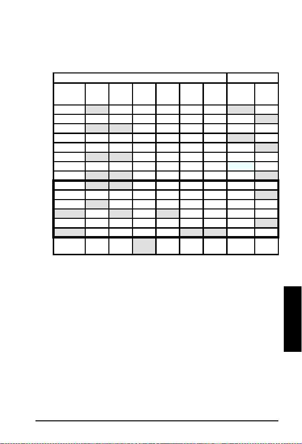
Paper Weight Equivalence Table
(Approximate)
Shaded areas indicate a standard weight for that grade.
US Weights (lb) or Thickness (mm) Metric Wt (g/m2)
PostCard *
thickness
1
2
3
4
5
6
7
8
9
10
11
12
13
14
15**
* US Post Card measurements are approximate. Use for reference only.
** This media weight (row 15) may perform to your satisfaction but is beyond the printer’s
specifications. Printing with this media weight will not damage the printer.
Bond WtText
16 41 22 27 33 37 60 60
17 43 24 29 35 39 64 64
20 50 28 34 42 46 75 75
21 54 30 36 44 49 80 80
22 56 31 38 46 51 81 81
24 60 33 41 50 55 90 90
27 68 37 45 55 61 100 100
28 70 39 49 58 65 105 105
32 80 44 55 67 74 120 120
34 86 47 58 71 79 128 128
36 90 50 62 75 83 135 135
.18 39 100 55 67 82 91 148 148
.19 42 107 58 72 87 97 157 157
.20 43 110 60 74 90 100 163 163
.23 47 119 65 80 97 108 176 176
CoverWtBristol WtIndex WtTagWtEurope Japan
Book
Wt
5A - 5
5
A
Page 59

Media Specifications
Understanding Ream Labels
Standard ream and carton labels contain such standard information as:
A Grade
B Basis weight
C Size
D Printing surface (as indicated by the ream arrow)
E Basis weigh t (repeat ed)
F Grain (long or short)
G Number of sheets
AB C
GF E D
Figure 5-2
5A - 6
Ream Label Example
Page 60

Media Specifications
Paper Troubleshooting
Paper problems are sometimes difficult to detect. The following series of steps
will help isolate paper-induced problems versus printer problems:
Isolat e a paper path.
Isolat e a paper brand.
Isolate a paper type.
Evaluate paper user practices.
Evaluate environmental conditions.
Some simple tips:
Turn the paper over and print on the other s ide (this often corrects
excess paper curl.
Rotate the paper 180 (end for end) to feed a different leading edge (can
help correct for multi-sheet feeding problems).
Papers to Avoid
NCR self-carbon (or “carbonless” paper).
Paper that has been preprinted (such as letterhead) with ink that will not
withstand fuser heat (200°C/392°F for 0.1 second).
Plastic-fiber paper.
Embos sed paper .
Paper with cutouts or perforations.
Chemicall y treated paper.
Coated paper.
Synthetic paper.
Multi-part forms.
Odd size d pa pe r .
If your printer is having trouble with paper jams, multi-feeds, or misfeeds, use
HP’s paper: HP 20# Multi-Purpose Paper, part # 9300-2092; HP 24# LaserJet
Paper, part # 9300-2091.
5A - 7
5
A
Page 61

Media Specifications
General Tips
Paper Curl
Paper curl is the result of the heating process used to bond the print image
(toner) to the paper, combined with the path paper must negotiate through the
printer .
Actions that can be perfo rmed to reduce curl a re as follows:
1 Turn the paper over in the input tray. Some paper packages (ream) have
an arrow indicating the preferred printing side. Experiment to determine
which orientation yields the least curl.
2 Try a different output paper path (if available for your printer). Using the
“face-u p” o utp ut pa th may yiel d mor e acce pt able resul ts th an th e st andar d
“face-down” output tray. Note that the LJ 5, 5M, and 5N printers have no
alternative output paper path. Use the LJ 5L/6L Front Output Slot and
Paper Input Support if output is curled or wrinkled.
3 Protect the paper from adve rse environmental cond itions prior to use.
Paper designed for laser printing has an initial moisture content of 4-6%
which is maintained as long as it is stored properly . Once the paper h as
been removed from its packagin g, it will dry out or absorb additi onal
moisture, depending on the environment. Excess moisture in the paper
will increase the amount of curl.
4 Try a different type or brand of print media. Not all paper is designed for
laser printing.
Much of the paper curl induced by the laser printer’s fusing process will tend to
relax within the first 24 hours foll owing printing. However , the curl on the
leading edge of the page may remain more permanent because it tends to
remain in contact with the fusin g roller for longe r periods of time.
Consult your printer’s User’s Manual and the “HP LaserJet Printer Family
Paper Specification Guide,” part number 5021-0368 for more information.
5A - 8
Page 62

Media Specifications
Envelope Specifications
Category Specifications
Basis Weight 20 to 24 lbs (75 to 90 g/m2) single layer
Caliper 3.3 to 5.5 mils (0.084 to 0.14 mm) single layer thickness
Curl Less than 0.2 in. (5 mm) curl across entire surface.
Finishing Accurate, sharply creased folds with no more than
Fusing
Compatibility
Moisture Content 4% to 6% by weight
Paper Must meet all the normal paper specifications.
Smoothness 100 to 250 Sheffield
Envelope Sizes
Metric System
Size Metric Dimensions U.S. Dimensions
DL 110 X 220 mm 4.3 x 8.6 in
C5 162 x 229 mm 6.4 x 9.1 in
B5 176 x 250 mm 7.0 x 9.9 in
Imperial (U.S.) System
Size U.S. Dimensions Metric Dimensions
Commercial #10 4.1 x 9.5 in 105 x 241 mm
Monarch #7 3/4 3.9 x 7.5 in 98 x 191 mm
two thicknesses of paper at the leading edge.
Must not scorch, melt, offset or release hazardous
emissions when heated to 200°C (392°F) for 0.1 second.
Envelopes to Avoid
With clasps, snaps, or tie strings.
With transparent windows, holes, perforations, or cutouts.
Having a n open flap with adhes ive exposed.
Using pap er, inks, adhesives, or materi als that discolor, melt, offset or
release hazardous emissions when exposed to 200°C (392°F) for 0.1
second.
Extremely smooth, shiny, rough, textured, or deeply embossed.
Very rough, textured, or deeply embossed envelopes.
Damaged, wri nkled, or irreg ularly shaped.
Use of encapsulating adhesives that do not require moistening, but rely
instead on pressure to seal them.
5
A
5A - 9
Page 63

Media Specifications
Printer Malfunctions Due to Envelopes
Printer malfunctions caused by envelopes can best be avoided by the following
preve nti ve meas ur es:
Carefully feeding the envelope into the printer.
Being aware of envelope construction.
The fol lowi ng summ arize s pr event ati ve acti ons f or ea ch ca se.
Envelope Feeding
Envelopes may be manually fed through the printer or an envelope tray
or a feed er ma y be us ed.
Closely inspect the leading edge of the envelopes before feeding them
into the printer. Ensure the leading edge is flat. Watch for envelope
curl and dog ears. Flatten the leading edge of the en velope before
printing.
Be patient, in manual feed mode the printer displays a message when it
is ready to accept the next envelope. Always wa it for this message to
appear bef ore inserting th e next envelope.
Do not allow a large quantity of envelopes to accumulate in the output
tray.
On most printers, the rear (or front) output tray should be used when
available when printing envelopes not the top (face down) output.
Envelope Construction
Corner folds must be well-creased, with no more than two thicknesses
of paper.
Envelopes must lay flat.
Paper gr ain should be diagonal to the feed direction.
Adhesives must meet HP specifications for fusing compatibility.
Basis weight must not exceed 24 pounds.
Under no circumstances should envelopes have clasps, snaps, t i e
strings, or windows; nor should t hey use synthetic materials.
5A - 10
Page 64

Media Specifications
Label Specifications
Category Specifications
Adhesive Must not be on any external surfaces of the label
Caliper Must not exceed 0.007 in. (0.18 mm)
Curl In ream: flat within 0.2 in (5 mm)
Finishing Precision Cut sheet within 0.031 in. (0.79 mm) of nominal
Fusing Compatibility All adhesives, carrier sheets, top sheets, and
Packaging Moisture proof wrap to preserve properties.
Printer Malfunctions Due to Adhesiv e Labels
As with envelopes, printer malfunctions caused by adhesive labels can best be
avoided through prevention. To prevent paper jams and feed problems, labels
must:
Be cut long grain (as oppose d to short grain).
Totally cover the carrier sheet (no spaces between labels, or removed
labels).
Contain no excessive glue. (The adhesive should be acrylic-based
emulsion and should not come into direct contact with the printer.)
Meet HP specifications for fusing compatibility.
Meet HP specifications for caliper.
Have a carrier sheet that is not too smooth.
The flat paper path (manual feed slot and rear, or front, face-up
delivery door) is the recommended printing method.
before, during, or after printing. Label
construction and die-cutting must not allow
labels to peel off during transport, printing, or
fusing.
and 0.20° square.
other materials used in label construction must
be compatible with the heat and pressure of the
fusing process. Materials must not discolor,
melt, offset, or release hazardous emissions
when heated to 392°F (200°C) for 0.1 second.
5
A
5A - 11
Page 65

Media Specifications
Transparency Specifications
Category Specifications
Caliper 3.9 to 4.3 mils (0.100 to 0.110 mm)
Cutting Angle
Finishing Precision Cut sheet to within 0.03 in. (0.8 mm) of nominal
Fusing Compatibility Overhead transparency material must be
90° ± 0.2°
and ± 0.2° of square.
compatible with the heat and pressure of the
fusing process. Materials must not discolor,
melt, offset material, or release hazardous
emissions when heated to 392° F (200° C ) for
0.1 second.
Printer Malfu nctions Due to Transparen cies
To prev ent pri nter malf unc tio ns du e to t ran spar enci es:
Use the straightest paper path to avoid curling and other problems.
Use transparencies with the correct resistiv ity.
Use transparencies which meet HP specif ication s fo r f us ing
compatibility.
Remove each printed s heet from the tray and p lace it on a flat surface
before printing the next sheet.
HP Paper Training Video Tape
HP has developed a training video focusing on how paper is manufactured and
how the manufacturing process rela tes to its use in HP LaserJet Printers. Part
numbers are shown below.
The Paper Video explains the
manufacturing process.
5A - 12
Part No.
5961-0711 NTSC Version
5961-0712 PAL Version
Version
(VHS Format)
Page 66

6A
Toner Cartridge Information
Toner Car tridge
Information
6A - 1
Page 67

Toner Cartridge Information
Cartridge Weights/Page Counts
HP LaserJet Product Cartridge Full Weight Empty Weight Page Count
5L/6L C3906 A EP-A 730 gm (25. 7
5P/6P C3903A EP-V 9 20 gm (32. 8
5 92298A EP-E 150 0 gm (52 .9
5Si C3909A EP-W 3034 gm (1 06 .8
oz.)
oz)
oz)
oz)
630 gm (22 oz) 2 ,500
740 gm (26 oz) 4,000
1220 gm (43 oz) 6,800
2315 gm (81.5
oz)
@ 5%
Coverage
15,000
Potential Toner Cartridge Issues
Banding
When printing with a laser printer , the toner is appli ed across the page in
horizontal strips. The page is moved through the printer and toner is continually
applied. When printing text, or black pages a large amount of toner is deposited
on the page. As the amount of toner deposited on the page decreases, slight
speed variations become more apparent. As the resolution (dots per inch) and
the speed (pages per minute) increase, a variation in patt ern intensity may
appear on the page as lines or bands.
The bands are more visible in certain gray-scale patterns. High speed printers,
that are capable of printing high resolution grayscale patterns, are more likely to
display the p attern variat ions. C hanging t he gray-scale pat tern or re ducing the
resolution may si gnificant ly reduce t he amount o f banding t hat occurs.
Character Voids
Small gaps or voids may appear in some of the characters when printing on
media other than standard photocopier paper. These “character voids” occur
because some print media does not accept the transfer of toner as well as others.
To minimize the occurrence of character voids, avoid media with a rough finish.
Use media that is within Hewlett-Packard’ s paper specif ications listed in the
User’s Manual. If the finish is too rough, th e surface will consist of large
inconsistencies. If the finish is too smooth , toner will not adhere well.
Adjusting the print density may effect the severity of character voids.
6A - 2
Page 68

Toner Cartridge Information
Toner Cracking
When paper is folded and the crease happens to line up with a line of text it is
possible with certain types of paper for the text to break along the line, giving
the appearance of a white line through the text. Papers which do not meet the
smoothness (100-250 Sheffield, 100-500 Bendtsen) and/or W ax Pick (>11
Dennison) are likely to exhibit th is effect more than other s.
Toner in the HP LaserJet printer s is comprised of minute particles of pi gmented
plastic material (styrene) and iron oxide. When the toner is subjected to the
fusing temperature, these individual iron-impregnated plastic particles become
part of a larger plastic image on the page. When the printed page is
subsequently folded, the plastic image must also give, in some fashion, in order
to accommodate the fold. If the print image has been well -set into the paper ,
this resulting break in the plasti c will not be apparent. However, if the toner is
unable to adequately penetrate the paper fibers or if, in the process of folding
the paper, the paper fibers behind the toner break away from the page itself, the
result will be a “white line” through the image. There are several ways to
minimize this effect:
Ensure paper being used meets ALL of the specifications provided in
the HP LaserJet Printer Family Paper Specification Guide, part
number 5021-0368, in parti cular the smoothn es s and wax pick.
A lighter density setting will ensure that the toner image will be
comprised of less plastic material, thus minimizing the resulting effect
of trying to fold the toner image.
A lighter character stroke width might also help for the same reasons
given above.
MICR (Magnetic Ink Character Recognition) paper may fix toner
crackin g problems (see also HP MICR User’s Guide, HP part number
5091-3857).
Paper with a laid finish will normally cause problems when doing xerographic
(laser) printing, particularly due to its surface roughness. Relatively “stiff”
papers (as compared to a xerographic bond paper) are not ideal for folding in
the first place and again will present problems when attempting to do so with a
toner image applied to the surfa ce.
6A - 3
6
A
Page 69

Toner Cartridge Information
Post Image Transfer
After printing a document on an HP LaserJet printer, folding it, and sending it
through the mail, a portion of the print im age may be transferred to opposing
surfa ces o f the f old ed doc ume nt.
EXPLANATION:
The laser printing process uses a pigmented plastic powder (toner) to form a
print image that is first transferre d to a sheet of paper (or other print medium)
and th en me lte d (fus ed) o nt o the surfac e of t he p aper to for m a per mane nt
image. Though paper is usually thought of as being “soft”, it is actually quite
abrasive. When the printed page is folded, movement under pressure between a
paper surface and the toner image may cause the paper to abrade (scratch) the
toner, causing a transfer of the toner material onto the opposing surface of the
paper. This can be demonstrated by rubbing a print image against (or into) a
clean sheet of paper.
Some machinery, such as that used by the US Postal Service to sort mail, can
apply the necessary pressure and agitation to cause this toner image transfer
phenomenon.
RESOLUTION:
The potential for this problem can be significantly reduced by minimizing the
amount (or height) of toner used to produce the print image, using a paper that
is less abrasive, and/or ensuring optimal fusing of the toner (print) image to the
paper.
The amount of toner used to produce a print image is controlled by the print
density dial, slide, or Control Pane l settings in the HP LaserJet p rinters. The
print density should be adjusted for a LIGHTER image to reduce the amount
(height) of toner prone to abrasive transfer.
The HP LaserJet printers have been designed for optimum results with
xerographic (or “laser”) bond papers, such as XEROX 4024 photocopy paper.
The properties of this type of paper (surface roughness, composition, moisture
content, etc.) are such that the other causes of potential toner transfer are
minimized. Photocopy papers are typically less abrasive than other types of
paper (such as “writing bond”) and are also formulated to ensure optimal fusing
of the toner image. Using other types of paper will generally yield less than
optimal results in laser print ers. For help in selecting paper suitabl e for use in
the HP LaserJet printers, refer to the HP LaserJet Printer Family Paper
Specification Guide - part number 5021-0368. This guide can be ordered by
calling HP Parts Direct at 800-227-8164 in the U.S., or HP Distribution at
970-339-7009.
6A - 4
Page 70

Toner Cartridge Information
There is presently no way to entirely eliminat e the possibility of tone r transfer
due to the way in which laser printing is accomplished. However, using these
techniques should yield more satisfactory results and will often reduce the
problem to imperceptible le vels.
Gray Background on Env elo pes
Poor print quality is normally the result of using envelopes that are of the
incorrect weight or finish. The paper used in the envelope’s construction may be
either too heavy, too rough or too slick, embossed, or made in such a way that it
is incompatible with the high temperatures encountered in toner fusing. In the
end, the toner just doesn’t adhere well to the surface. Also, when using heavier
envelopes, a gray background may appear on the front (or print side) of the
envelope. To reduce the gray background, the print density may need to be set to
a darker setting. (On the LaserJet 5, ‘‘5’’ is the darkest setting and “1’’ is the
lightest.)
6A - 5
6
A
Page 71

Toner Cartridge Information
Recycling Program
The HP Toner Cartridge Recycling Program is here. The U. S., Canada, Europe,
and Australia now have recycling programs. The old Toner Cartridge and
cleaning pad should be put in the silver wrapper and box that the new cartridge
came in and se nt ba ck f or re cycl in g.
THE U.S.
CANADA
AUSTRALIA
EUROPE
Note
There is a brochure that explains the recycling program in the U.S. The
part number is 5091-1325EUS. The customer sends back used Toner
Cartridges via UPS at no cost to the customer using shipping labels
sent in the brochure. The Toner Cartridges can be sent one at a time
or in volume shipments. Some of the parts are recycled to make new
cartridges. Other parts are melted for re-use as raw material. If the
customer has any questions, and to receive the free recycling
brochure, refer them to the Customer Information Center at
1-800-752-0900.
Canada uses Federal Express for their recycling program. At least 8
but no more than 40 Toner Cartridges can be sent at one time.
Shipments of less than eight cartridges are at the shipper’s expense.
Call Federal Express at 1-800-GoFedEx (1-800-463-3339) to arrange
free pickup of the bundled cartridges. Fill out a Federal Express
Waybill or obtain a preprinted one from your dealer.
In Alberta, B.C., Manitoba, NWT,
Saskatchewan, and the Yukon,
send the bundles to:
In the Atlantic provinces,
Ontario and Quebec
send the bundles to:
For more information call: Canada wide: 1-800-387-3867
Australian customers send their Toner Cartridges to their local HP
dealer. If more than 30 cartridges a month are used, the local dealer
can be contacted for instructions on how to have the cartridges picked
up directly from the customer’s site. For further information, contact the
dealer or local HP sales office.
The recycling program in Europe currently includes these countries:
Germany, Switzerland, Austria, United Kingdom, the Netherlands, and
Sweden. If more than 30 cartridges a month are used, the local dealer
can be contacted for instructions on how to have the cartridges picked
up directly from the customer’s site. For further information, contact the
dealer or local HP sales office.
Hewlett-Packard Toner Cartridge
Recycling Program
6551 Westminister Hwy,
Unit 160
Richmond, B.C. V7C 4V4
Acct. No.: 1246-1740-5
Hewlett-Packard Toner Cartridge
Recycling Program
6600 Goreway Drive, Unit C
Mississauga, Ontario L4V 1S6
Acct. No.: 1246-1740-5
Dept. 129
Toronto: 1-800-678-9430
Ext. 4981
Recycling inform atio n is now also i nclu ded in t he
toner cartridge package.
6A - 6
Page 72

Toner Cartridge Information
Re-fill Statement
Hewlett-Packard toner cartridges have been designed to maximize the
reliability of the HP LaserJet printer by including all of the components that
need fr equ ent r epl acem ent o r adj ustm ent wi th in t he ca rtri dge . Whi le we
recognize that all parts of this crit ical printer mechanism wil l not wear
consistently, the HP toner cartridge has been designed to optimize the
exceptional print quality that is synonymous with the HP LaserJet printer name.
While Hewlett-Packard does not prohibit the use of refilled toner cartridges
during the warranty period or under a maintenance contract, we also do not
recommend their use fo r the followi ng reasons:
1 The HP LaserJet toner cartridge is not designed to be refilled or
remanufactur ed.
2 Hewlett-Packard has no contro l or process to ensure that a refill ed toner
cartridge will function at the high level of reliabilit y of a new HP LaserJet
toner cartridge. Hewlett-Packard also cannot predict what the long-term
effect on the printer’ s reliability could be from using diff erent toner
formulations found in refilled cartridges. Because the HP LaserJet printer
has the highest reliability reputation in the industry, we are concerned
about any usage that might affect this reputation.
3 Hewlett-Packard has no control over the actua l print quality of a refill ed
toner cartridge. The print qua lity of the HP LaserJet t oner cartrid ge
directly influen ces the customer’s perc eption of the HP LaserJet printer
itself. The high print quality of the HP LaserJet printer is one o f the
primary reasons for the success of the product and we are keenly
interested in maintaining th at image.
6A - 7
6
A
Page 73

Toner Cartridge Information
The entire family of HP LaserJet printers are covered under a standard one-year
warranty from the date of purchase. Hewlett-Packard offers optional
maintenance contracts after the one-year warranty expires. The use of refilled
toner cartridges alone does not affect either the warranty or any maintenance
contract purchased from HP . However , if an HP LaserJet pr inter failur e or
damage is found to be directly attributed to the use of a refilled toner
cartridge, the repair will not be covered under the warranty or by the
maintenance contract. Rather, standard time and material char ges will be
applied to service the printer fo r that particu lar failure or damage.
Hewlett-Packard is constantly striving to provide the highest quality printer
products possible. The HP LaserJet printer family was designed for optimum
output performance when the printing mechanism is periodically replaced with
a new HP toner cartridge. The HP toner cartridge is designed specifically to
enhance the output from the HP LaserJet family of printers. We know that the
highest quality print results will be obtained when new HP toner cartridges are
used with HP Laser Jet pri nters .
6A - 8
Page 74

Printer Options and User Replaceable Parts
7A
Printer Opt ions
and User
Replaceable
Parts
7A- 1
Page 75

Printer Options and User Replaceable Parts
Product
Memory
Language
Emulation
Boards
I/O
Envelope
Feeder
Duplex
Service
Maint./ PM
Kits
Cleaning
Tool
Disk Drive
Sheet
Feeder/
Stacker
Product
Number
C2063A 1MB SIMM 36 Bit C2063A
C2064A 2 MB SIMM 36 Bit C2064A
C2065A 4 MB SIMM 36 Bit C2065A
C2066A 8 MB SIM M 36 Bit (IIISi S/ N 3200 & up) C2066A
C3130A 1MB SIMM 32 Bit C3130-60001
C3131A 2 MB SIMM 32 Bit C3131-60001
C3132A 4 MB SIMM 32 Bit C3132-60001
C3133A 8 MB SIMM 32 Bit C3133-60001
C3146A 16 MB SIMM 32 Bit C3146A
C3939A 1 MB JEIDA C3939A
C3938A 2 MB JEIDA C3938A
C3148A 4 MB JEIDA C3148A
C3930A 2MB FLASH SIMM C3930A
C3931A 4MB FLASH SIMM C3931A
C3152A PostScript Level 2 SIMM C3152-69001*
C3169A PostScript Level 2 SIMM C3169A-69001*
C3918A PostScript Level 2 SIMM C3918-69001*
C3987A PostScript Level 2 SIMM C3987-96001*
J2550A JetDirect Card for Ethernet/10Base-T J2550-69001*
J2552A JetDi re c t Car d fo r 1 0B a se - T/ BN C/ L T a lk J2552-69001*
J2555A JetDirect Card for Token Ring J2555-69002*
J2374C JetDirect Network Software/HP-UX N/A
J2375C JetDirect Network Software/Sun Unix N/A
J2382A/B JetDirec t EX for
J2591A JetDi re c t EX fo r
C3927A Envelope Feeder C3927-69001*
C3765A Envelope Feeder C3765-60501
C3920A Duplexer Upgrade
C3762A Duplexer Upgrade C3762-60501
C3971A Servic e M ain t enance Kit with 110V fuser C3971-69001*
C3972A Servic e M ain t enance Kit with 220V fuser C3972-69001*
C2965A Disk Drive C2965-69001*
C3763A 2000 Sheet Input (Tray 4)
Product Description
Ethernet/10Base-T/BNC
Ethernet/10Base-T/BNC
Service Maintenance Kit with 110V fuser C3916-69001*
Service Maintenance Kit with 220V fuser C3916-69002*
5P Cleaning Brush RF5-0593-000CN
Service
Part Numb er
J2382-69003 *
J2591A
7A - 2
Page 76

Printer Options and User Replaceable Parts
5 5P 5L 5Si 6P 6L
•
•
•
•
•
•
•
•
•
•
•
•
••
••
••
••
••
•
•
•
•
•
•
•
•
•
••
••
••
•
•
••
••
••
••
••
••
•
•
7
A
•
•
•
•
•
•
•
•
•
•
•
•
•
7A- 3
Page 77

Printer Options and User Replaceable Parts
Product
Paper
Trays
I/O
Cables
Toner
Prod or P art
Number
R75-4000-000CN Universal Paper Cassette
C3921A Optional Lower Cassette w/ Tray 3
C3924A 250 Sheet Universal Cassette
R77-0003-000CN Tray 2
R77-0004-000CN Tray 3
R98-4000-000CN Universal Paper Cassette
C2950A Parallel IEEE-1284 compliant A to B (2.0 m)
C2951A Parallel IEEE-1284 compliant A to B (3.0 m)
C2946A Parallel IEEE-1284 compliant A to C (3.0 m)
C2947A Parallel IEEE-1284 compliant A to C (10.0 m)
C2933A Serial 25 pin-F / 9 pin-M
C2932A Serial 9 pin-F / 9 pin-M
92298A HP Toner Cartridge
C3903A HP Toner Cartridge
C3906A HP Toner Cartridge
C3909A HP Toner Cartridge
Product Description
7A - 4
Page 78

Printer Options and User Replaceable Parts
5 5P 5L 5Si 6P 6L
•
•
••••••
••••••
•
•
•
•
•
•
•
•
•
••
••
•
•
•
7
A
7A- 5
Page 79

Printer Options and User Replaceable Parts
7A - 6
Page 80

8A
Parts
8A - 1
Page 81

A F
B G
C H
D I
A AE J
Figure 8A - 1
8A - 2
Common Hardware
Page 82

Common Hardware
XB1-2300-606CN M3 x 5mm Pan-head Phillips
A
XB1-2300-507CN M3 x 5mm Pan-head Phillips
A
XB1-2300-607CN BH3 x 6mm Pan-head Phillips
A
0515-1895 M3 x 8mm Pan-head Phillips
A
XB1-2301-407CN M4 x 14mm Pan-head Phillips
A
XB1-2400-606CN M4 x 6mm Pan-head Phillips
A
XB1-2400-809CN M4 x 8mm Pan-head Phillips
A
0515-1912 M4 x 8mm Pan-head Phillips
A
XB1-1300-807CN M3 x 8 mm Pan-head Phillips
A
XA9-0434-000CN M3 x 4mm Washer-head Phillips
B
XA9-0267-000CN M3 x 6mm Washer-head Phillips
B
XA9-0253-000CN M3 x 8mm Washer-head Phillips
B
XA9-0542-000CN M3 x 10mm Washer-head Phillips
B
XA9-0540-000CN M4 x 8mm Washer-head Phillips
B
XA9-0653-000CN M3 x 6mm Star-washer Phillips
C
XA9-0389-000CN M3 x 8mm Star-washer Phillips
C
XA9-0654-000CN M3 x 10mm Star-washer Phillips
C
XA9-0192-000CN M4 x 6mm Star-washer Phillips
C
XA9-0828-000CN M3 x 6mm Star-washer Phillips
C
RBI-5552-000CN M3 Shoulder Screw Phillips
D
RAI-7636-000CN M3 Shoulder Screw Phillips
D
RBI-5489-000CN M3 x 4mm Shoulder Screw Phillips
D
XA9-0342-000CN M3 x 8mm Shoulder Screw Phillips
D
XB4-7300-609CN M3 x 6mm Self-tapping Phillips
E
XB4-7400-809CN M4 x 8mm Self-tapping Phillips
E
XB4-7401-009CN M4 x 10mm Self-tapping Phillips
E
XB4-7401-007CN M4 x 10mm Self-tapping Phillips
E
XB4-7401-209CN M4 x 12mm Self-tapping Phillips
E
XB6-7300-607CN M3 x 6mm Self-tapping Phillips
E
XA9-0253-000CN M3 x 8mm Loose Flat/Lock Washer Phillips
F
XA9-0584-000CN M3 x 12mm Loose Flat/Lock Washer Phillips
F
FA9-1449-000CN Star-washer trus-head Phillips
G
XB1-2302-507CN M3 x 25mm Trus-head Phillips
G
XB6-7300-809CN M3 x 8mm Trus-head Phillips
G
XA9-0326-000CN M3 x 4mm Trus-head Phillips
G
XB6-7300-807CN M3 x 8mm Trus-head Phillips
G
XD2-1100-242CN 2.4mm Retaining Ring (e-type)
H
XD2-1100-322CN 3.2mm Retaining Ring (e-type)
H
XD2-1100-402CN 4.0mm Retaining Ring (e-type)
H
XD2-1100-502CN 5.0mm Retaining Ring (e-type)
H
XD2-1100-642CN 6.4mm Retaining Ring (e-type)
H
XG9-0260-000CN Retaining Ring (e-type)
H
XD2-2300-507CN 5.0mm Grip Ring (c-type)
H
XA9-0375-000CN 3m x 25 mm Loose Flat/Star Washer Phillips
I
XA9-0686-000CN M3 x 6mm Hexhead Screw
J
XA9-0724-000CN M3 x 8 mm Hexhead Screw
J
XA9-0824-000CN M3 x 10mm Hexhead Screw
J
XA9-0813-000CN M3 x 8mm Hexhead Screw w/ washer
J
Common Hardwa re
8
A
8A - 3
Page 83

LJ 5 Parts
LJ 5 Parts
A
Figure 8A - 2
RG5-0475-060CN Paper Output Sensor Assembly
A
RG5-2189-000CN Paper Output Assembly
B
C2037-69004* DC Controller PCA
C
C2037-69008* Laser/Scanner Assembly
D
C3919-69001* Formatter PCA
E
RB1-2205-000CN Tray 1 Pickup Roller
RB1-7911-000CN Tray 2 Pickup Roller
RB1-7983-000CN Tray 3 Pickup Roller
RB1-2133-000CN Paper Out Sensor Flag
RF5-0343-000CN Tray 1 Separation Pad
RF5-0349-000CN Transfer Roller
B
LJ 5 Parts
LJ 5 Parts
* Rebuilt part, require s exchange
C
D
E
8A - 4
Page 84

LJ 5 Parts
A
B
C
D
E
8
A
F
I
Figure 8A - 3
G
H
LJ 5 Parts
8A - 5
Page 85

LJ 5 Parts
C2037-69001*
A
C2037-69002*
RH7-1169-000CN Main Motor
B
C2037-69006*
C
C2037-69007*
C3916-69005* Paper Feed Assembly
D
RG5-2238-000CN Display Assembly (without overlay)
E
RG5-0469-020CN Transfer Guide Assembly
F
RG5-0512-070CN Paper Control PCA
G
RG5-0514-000CN Sensor PCA
H
C2037-69009* High Voltage PCA
I
Rebuilt part, requires exchan ge
*
110V Fusing Assembly
240V Fusing Assembly
110V Power Supply
240V Power Supply
8A - 6
Page 86

LJ 5 Duplexer Parts
LJ 5 Parts
A
B
C
D
EF
Figure 8A - 4
A
B
C
D
E
F
G
H
I
J
K
L
LJ 5 Duplexer (cross section)
RH7-1235-000CN Switchback Fan
RF1-3814-000CN Switchback Stepper Motor (M2)
RG1-3529-000CN Switchback Sensor Cable
RF1-3808-000CN Switchback Solenoid (SL1)
RF1-3813-000CN Rear Holding Tray Motor (M3)
RG1-3503-000CN Power Supply Assembly
RG1-3582-000CN Duplex Control PCA
RA2-2072-000CN Timing Belt
RA2-2076-000CN Sensor Arm
WG8-5210-000CN Photosensor (PS2)
RG1-3530-000CN Paper Pickup Cable
RF1-3815-000CN Front Holding Tray Motor (M1)
GHIJK
L
8
A
8A - 7
Page 87

LJ 5P/6P Parts
LJ 5P/6P Parts
A B
Figure 8A - 5
8A - 8
C D E F
LJ 5P/6P Parts
Page 88
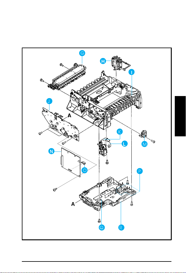
LJ 5P/6P Parts
G
H
I
J
8
A
K
R
Figure 8A - 6
N
T
O
LJ 5P/6P Parts (continued)
L
Q
R
M
P
8A - 9
Page 89

LJ 5P/6P Parts
RG5-1799-000CN 5P
A
RG5-2786-000CN 6P
RF5-1290-000CN 5P
B
RF5-0596-000CN 6P
RG5-1786-000CN Mirror Assembly
C
C3150-69005* 5P
D
C3980-69005* 6P
R75-4000-000CN 5P
E
R98-1001-000CN 6P
C3903A Toner Cartridge
F
C3150-69003* 5P
G
C3150-69004* 5P
C3980-69003* 6P
C3980-69004* 6P
RG5-1801-000CN 5P
H
RG5-2776-000CN 6P
RG5-1698-000CN
I
RF5-1283-000CN
RG5-1713-000CN 5P
J
RG5-2778-000CN 6P
RG5-1692-000CN 5P
K
RG5-2796-000CN 6P
RG5-1693-000CN 5P
RG5-2790-000CN 6P
RB1-6332-000CN Pick-up Roller (tray 2)
L
RB1-2205-000CN Tray 1 Roller
M
C3151-69001* 5P
N
C3981-69001* 6P
RG5-1719-000CN High Voltage Connector Assembly
P
RH7-1258-000CN 5P
RH7-5160-000C 6P
C3150-69001* 5P
R
C3150-69002* 5P
C3980-69001* 6P
C3980-69002* 6P
RG5-1702-000CN 5P
RG5-1703-000CN 5P
RG5-2802-000CN 6P
RG5-2803-000CN 6P
RG5-1801-000CN 5P
RG5-2776-000CN 6P
RG5-0593-000CN
RB1-5939-000CN
5062-4661
Motor Assembly
Motor Assembly
Transfer Roller Assembly
Transfer Roller Assembly
Laser Scanner Assembly (exchange)
Laser Scanner Assembly (exchange)
Complete Tray 2 Assembly
Complete Tray 2 Assembly
Complete Fuser Assembly (100-120V) (exchange)
Complete Fuser Assembly (220-240V) (exchange)
Complete Fuser Assembly (100-120V) (exchange)
Complete Fuser Assembly (220-240V) (exchange)
Fan Assembly
Fan Assembly
Top Oblique Roller Assembly
Static Charge Eliminator
Gear Train Assembly
Gear Train Assembly
Pick-up Assembly (tray 2)
Pick-up Assembly (tray 2)
Complete Tray 1 Pickup Assembly
Complete Tray 1 Pickup Assembly
Formatter PCA (exchange)
Formatter PCA (exchange)
Tray 1 Solenoid (SL2)
Tray 1 Solenoid (SL2)
DC Controller PCA (110-120V) (exchange)
DC Controller PCA (220-240V) (exchange)
DC Controller PCA (110-120V) (exchange)
DC Controller PCA (220-240V) (exchange)
Hot Roller 120V
Hot Roller 220V
Hot Roller 120V
Hot Roller 220V
Fan
Fan
Brush, Mirror
Sensor Arm, Tray 1
Infrared Communication Test Tool
LJ 5P/6P Parts (see Figures 8A-5&6)
Rebuilt part, requires exchan ge
*
**Cover assembly does not include items C, E, and F.
8A - 10
Page 90

LJ 5L/6L Parts
LJ 5L/6L Parts
8
A
Figure 8-7
LJ 5L/6L Parts
8A - 11
Page 91

LJ 5L/6L Parts
RB1-7177-000CN Paper Feed Frame
A
RG5-1940-000CN 5L
B
RG5-3486-000CN 6L
C3941-69001 5L
C
RG5-3506-000CN 6L
C3941-69002 5L
C
RG5-3509-000CN 6L
RF5-1534-000CN Transfer Roller
D
RF5-1530-000CN 5L
D
RF5-2358-000CN 6L
RG5-1942-000CN 5L
E
RG5-3485-000CN 6L
RG5-2012-000CN 5L
F
RG5=3474-000CN 6L
RG5-2028-000CN Control Panel PCA
G
RG5-2013-000CN 5L
H
RG5-3475-000CN 6L
C3942-67902 5L
C3991-60001 6L
C3942-69002 5L Formatter (exchange)
RG5-1964-000CN 5L
RG5-3459-000CN 6L
RG5-1965-000CN 5L
RG5-3463-000CN 6L
RH7-1282-000CN 5L
RH7-1320-000CN 6L
RF5-1516-000CN 5L
RF5-2362-000CN 6L
RG5-2000-000CN 5L
RG5-3494-000CN 6L
C3941-69003 5L Laser Scanner (exchange)
RY7-5005-000CN Gear Kit #1
RY7-5006-000CN 5L
RY7-5036-000CN 6L
RY7-5007-000CN Fuser Release Kit
RY7-5008-000CN Separation Pad Kit
RY7-5009-000CN Input Sensor Arm Kit
RG5-2029-000CN Paper Pickup Cable
RG5-2031-000CN 5L
RG5-3662-000CN 6L
RG5-2032-000CN Thermistor Cable
LJ 5L/6L Parts (see Figure 8-7)
Pick-up Roller Assembly
DC Controller PCA, exchange (110V)
DC Controller PCA, exchange (220V)
Transfer Roller Guide
Feed Assembly
Delivery Assembly
Separation Guide Assembly
Formatter (new)
Heating Element (110V)
Heating Element (220V)
Main Motor
Pressure Roller
Laser Scanner (new)
Gear Kit #2
Door Sensor Cable
8A - 12
Page 92

RG5-2033-000CN Motor Cable
RG5-2034-000CN 5L
RG5-3661-000CN 6L
RG5-2035-000CN 5L Laser Cable
RG5-2036-000CN 5L
RG5-3499-000CN 6L
RG5-2037-000CN 5L Door Switch Cable
Scanner Cable
Control Panel Cable
LJ 5L/6L Parts
8
A
8A - 13
Page 93

LJ 5Si Parts
LJ 5Si Parts
Figure 8-8
8A - 14
LJ 5Si Parts
Page 94

Ref Part Number Description
RF5-1412-000CN Transfer Roller
A
RH7-1260-000CN Main Motor
B
RG5-1874-000CN Face-Down Delivery Assembly
C
C3166-69001 Fusing Assembly 100-120v, Exchange
D
C3166-69002 Fusing Assembly 220-240v, Exchange
D
RG5-1834-000CN Feeder Assembly
E
RG5-1833-000CN Registration Assembly
F
C3166-69009 Tray 1 Pick Up Assembly, Exchange
G
RB1-6730-000CN Tray 1 Feed Roller
H
RF5-1455-000CN Tray 1 Separation Pad
I
C3166-69004 Paper Input Unit (PIU), Exchange
J
RG5-1847-000CN Main Gear Assembly
K
RG5-1887-000CN Transfer Roller Assembly
L
RG5-1884-000CN Tray 1 PCA
M
LJ 5Si Parts
8
A
8A - 15
Page 95

LJ 5Si Parts
LJ 5Si Parts
Figure 8-9
Ref Part Number Description
A
B
C
D
E
LJ 5Si Parts
C3166-69006 Laser/Scanner Assembly, Exchange
RH7-1266-000CN Fan 1
RG5-1846-000CN Switch/Sensor PCA
C3166-69005 High Voltage Power Supply, Exchange
C3166-69010 DC Controller PCA, Exchange
RG5-2433-000CN Front Panel (Control Panel Display) not shown
8A - 16
Page 96

LJ 5Si Parts
LJ 5Si Parts
8
A
Figure 8-10
Ref Part Number Description
A
A
B
C
D
E&F
LJ 5Si Parts
C3166-69007 Low Voltage Power Supply, 110-120v,
C3166-69008 Low Voltage Power Supply, Universal,
C3168-69005 Formatter, Exchange
RH7-1271-000CN Fan 3
RH7-1266-000CN Fan 2
RG5-1845-000CN Paper Size Sensing PCA, Trays 2 and 3
Exchange
Exchange
8A - 17
Page 97

LJ 5Si Mopier Parts
LJ 5Si Mopier Parts
G
H
F
E
D
I
C
Figure 8-11
8A - 18
B
A
LJ 5Si Mopier Paper Handling Components
Page 98

LJ 5Si Mopier Parts
Ref
A
B
C
C
D
E
F
G
H
H
I
Part Number
/Product Number
C3763A
C-3763-69501
RG5-2155-000CN Tray 4 Assembly
C3764-69100 Multi-Bin Mailbox (exchange)
C3766-69515 Mailbox with Stapler (exchange)
RB1-6822-000CN Duplex Unit Roller 1
C3762-60501 Duplex Unit
C3766-69500 Stapling Unit (exchange)
RB1-6491-000CN Face Up Bin
C3764-60504 External Paper Handling PCA
C40776-60500 External Paper Handling PCA
C3765-60501 Envelope Feeder
2000 Sheet Input Unit Assembly
(exchange)
(Multi-Bin Mailbox)
(Mailbox with Stapler)
Description
8
A
8A - 19
Page 99

LJ 5Si Mopier Parts
8A - 20
Page 100

9A
Service Notes
Summary and
Technical Tips
9A - 1
 Loading...