

HP ProLiant DL380 Gen9 User Manual

HPE ProLiant DL380 Gen9 Server
Abstract
This document is for the person who installs, administers, and troubleshoots servers and storage systems. Hewlett Packard Enterprise
Part Number: 768830-007
November 2016
Edition: 7
User Guide
assumes you are qualified in the servicing of computer equipment and trained in recognizing hazards in products with hazardous energy
levels.

© Copyright 2014, 2016 Hewlett Packard Enterprise Development LP
The information contained herein is subject to change without notice. The only warranties for Hewlett Packard Enterprise products and services
are set forth in the express warranty statements accompanying such products and services. Nothing herein should be construed as constituting
an additional warranty. Hewlett Packard Enterprise shall not be liable for technical or editorial errors or omissions contained herein.
Links to third-party websites take you outside the Hewlett Packard Enterprise website. Hewlett Packard Enterprise has no control over and is not
responsible for information outside the Hewlett Packard Enterprise website.
Microsoft® and Windows® are either registered trademarks or trademarks of Microsoft Corporation in the United States and/or other countries.
Linux® is the registered trademark of Linus Torvalds in the U.S. and other countries.
Red Hat® is a registered trademark of Red Hat, Inc. in the United States and other countries.
Java is a registered trademark of Oracle and/or its affiliates.
SD and microSD are trademarks or registered trademarks of SD-3C in the United States, other countries or both.
VMware is a registered trademark or trademark of VMware, Inc. in the United States and/or other jurisdictions.
Intel® and Xeon® are trademarks of Intel Corporation in the U.S. and other countries.

Contents
Component identification .......................................................................................................................... 7
Front panel components ........................................................................................................................................... 7
Front panel LEDs and buttons .................................................................................................................................. 9
UID button functionality ............................................................................................................................... 10
Power fault LEDs ......................................................................................................................................... 11
Access the optional HPE Systems Insight Display ................................................................................................. 11
Systems Insight Display LEDs ............................................................................................................................... 12
Systems Insight Display LED combinations ........................................................................................................... 13
Rear panel components ......................................................................................................................................... 14
Rear panel LEDs .................................................................................................................................................... 14
Flex slot battery backup module LEDs and buttons ............................................................................................... 15
System board components ..................................................................................................................................... 16
System maintenance switch ........................................................................................................................ 17
NMI functionality .......................................................................................................................................... 17
DIMM slot locations ..................................................................................................................................... 18
NVDIMM LEDs ............................................................................................................................................ 18
Non-hot-plug PCI riser board slot definitions ............................................................................................... 19
SAS and SATA device numbers ............................................................................................................................ 20
Hot-plug drive LED definitions ................................................................................................................................ 23
NVMe SSD components ........................................................................................................................................ 24
Hot-plug fans .......................................................................................................................................................... 24
Operations .............................................................................................................................................. 26
Powering up the server .......................................................................................................................................... 26
Power down the server ........................................................................................................................................... 26
Extend the server from the rack ............................................................................................................................. 26
Remove the server from the rack ........................................................................................................................... 27
Remove the access panel ...................................................................................................................................... 27
Install the access panel .......................................................................................................................................... 28
Access the product rear panel ................................................................................................................................ 28
Opening the cable management arm .......................................................................................................... 28
Remove the fan cage ............................................................................................................................................. 29
Remove the hot-plug fan ........................................................................................................................................ 30
Remove the PCI riser cage .................................................................................................................................... 30
Install the PCI riser cage ........................................................................................................................................ 31
Secure the full-length expansion board retainer ..................................................................................................... 32
Remove the air baffle ............................................................................................................................................. 32
Install the air baffle ................................................................................................................................................. 33
Setup ...................................................................................................................................................... 35
Optional services .................................................................................................................................................... 35
Optimum environment ............................................................................................................................................ 35
Space and airflow requirements .................................................................................................................. 35
Temperature requirements .......................................................................................................................... 36
Power requirements .................................................................................................................................... 36
Electrical grounding requirements ............................................................................................................... 37
Connecting a DC power cable to a DC power source ................................................................................. 37
Rack warnings ........................................................................................................................................................ 38
Identifying the contents of the server shipping carton ............................................................................................ 38
Installing hardware options ..................................................................................................................................... 39
Installing the server into the rack ............................................................................................................................ 39
Installing the operating system ............................................................................................................................... 40
Powering on and selecting boot options in UEFI Boot Mode ................................................................................. 41
Powering on and selecting boot options ................................................................................................................. 41
Registering the server ............................................................................................................................................ 42
Contents 3

Hardware options installation .................................................................................................................. 43
Hewlett Packard Enterprise product QuickSpecs ................................................................................................... 43
Introduction ............................................................................................................................................................. 43
Hot-plug drive guidelines ........................................................................................................................................ 43
Drive options .......................................................................................................................................................... 43
Removing the hard drive blank .................................................................................................................... 44
Installing a hot-plug SAS or SATA drive ...................................................................................................... 44
Removing a hot-plug SAS or SATA hard drive............................................................................................ 45
Installing the NVMe drives ........................................................................................................................... 45
6SFF NVMe Express Bay drive cage ..................................................................................................................... 46
Installing the airflow labels........................................................................................................................... 47
Installing the Express Bay drive cage.......................................................................................................... 48
Redundant hot-plug power supply option ............................................................................................................... 55
High-performance fan option .................................................................................................................................. 56
Processor and fan option ....................................................................................................................................... 58
Memory options ...................................................................................................................................................... 63
Memory-processor compatibility information ............................................................................................... 64
SmartMemory .............................................................................................................................................. 65
Memory subsystem architecture.................................................................................................................. 66
DIMM ranks ................................................................................................................................................. 67
Identifying DIMM and NVDIMMs ................................................................................................................. 67
Memory configurations ................................................................................................................................ 68
General DIMM and NVDIMM-N slot population guidelines ......................................................................... 70
Identifying the processor type...................................................................................................................... 71
Memory installation...................................................................................................................................... 71
Universal media bay option .................................................................................................................................... 75
2-slot PCI riser cage option .................................................................................................................................... 78
3-slot PCI riser cage option .................................................................................................................................... 80
GPU enablement kit ............................................................................................................................................... 82
Eight-bay SFF front drive cage option for bay 1 ..................................................................................................... 87
Eight-bay SFF front drive cage option for bay 2 ..................................................................................................... 91
Three-bay LFF rear drive cage option .................................................................................................................... 94
Two-bay SFF front drive cage option ..................................................................................................................... 99
Two-bay SFF rear drive cage option .................................................................................................................... 103
Systems Insight Display power switch module option .......................................................................................... 110
Location Discovery Services ear option ............................................................................................................... 112
Smart Storage Battery .......................................................................................................................................... 114
FlexibleLOM option .............................................................................................................................................. 115
Expansion board options ...................................................................................................................................... 117
Removing an expansion slot blank ............................................................................................................ 117
Installing an expansion board .................................................................................................................... 118
HPE H240 Smart HBA/P440, P840 Smart Array Controller ................................................................................. 119
HPE P440ar/P840ar Flexible Smart Array Controller ........................................................................................... 121
12G SAS Expander Card ..................................................................................................................................... 123
Rear serial port option .......................................................................................................................................... 130
M.2 SSD Enablement Board option ..................................................................................................................... 131
Installing an SSD module on the M.2 SSD Enablement Board ................................................................. 131
Installing an M.2 SSD enablement board .................................................................................................. 132
Dual 8Gb microSD Enterprise Midline USB device .............................................................................................. 134
750 W Flex Slot Hot Plug Battery Backup Module ............................................................................................... 134
Flex slot battery backup module configuration load support ..................................................................... 134
Installing the FSBBU ................................................................................................................................. 135
HP Trusted Platform Module option ..................................................................................................................... 136
Installing the Trusted Platform Module board ............................................................................................ 137
Retaining the recovery key/password........................................................................................................ 138
Enabling the Trusted Platform Module ...................................................................................................... 139
Cabling .................................................................................................................................................. 140
Cabling overview .................................................................................................................................................. 140
Two-bay SFF drive cage option cabling ............................................................................................................... 140
Three-bay LFF rear drive cage cabling ................................................................................................................ 144
Contents 4

Eight-bay SFF front drive cage cabling ................................................................................................................ 146
Express Bay Enablement Option cabling options ................................................................................................ 151
8SFF drive cage installed in bay 1 ............................................................................................................ 152
8SFF drive cage installed in bay 1 and 2SFF drives in the rear of the server ........................................... 153
Drive bay 1 is empty .................................................................................................................................. 154
8SFF drive cage installed in bay 1 and 2 SFF drives in the front of the server ......................................... 155
Host Bus Adapter and Controller cabling ............................................................................................................. 155
HPE H240 Smart Host Bus Adapter/Smart Array P440 Controller cabling ............................................... 156
HPE Smart Array P840 Controller cabling................................................................................................. 159
HPE Smart Array P440ar Controller cabling ............................................................................................. 160
HPE Smart Array P840ar Controller cabling ............................................................................................. 164
Universal media bay cabling ................................................................................................................................ 169
150W PCIe power cable option ............................................................................................................................ 172
M.2 SSD Enablement Board option cabling ......................................................................................................... 172
Software and configuration utilities ....................................................................................................... 174
Server mode ......................................................................................................................................................... 174
Product QuickSpecs ............................................................................................................................................. 174
HPE iLO ............................................................................................................................................................... 174
Active Health System ................................................................................................................................ 174
iLO RESTful API support ........................................................................................................................... 175
Integrated Management Log ..................................................................................................................... 176
Intelligent Provisioning ......................................................................................................................................... 176
Insight Diagnostics .................................................................................................................................... 176
Insight Diagnostics survey functionality ..................................................................................................... 177
Erase Utility ............................................................................................................................................... 177
Scripting Toolkit for Windows and Linux .............................................................................................................. 177
Service Pack for ProLiant ..................................................................................................................................... 178
Smart Update Manager ............................................................................................................................. 178
UEFI System Utilities ............................................................................................................................................ 178
Using UEFI System Utilities ....................................................................................................................... 179
Flexible boot control .................................................................................................................................. 179
Restoring and customizing configuration settings ..................................................................................... 179
Secure Boot configuration ......................................................................................................................... 180
Embedded UEFI shell................................................................................................................................ 180
Embedded Diagnostics option ................................................................................................................... 180
iLO RESTful API support for UEFI ............................................................................................................ 181
Re-entering the server serial number and product ID ............................................................................... 181
Utilities and features ............................................................................................................................................. 181
HPE Smart Storage Administrator ............................................................................................................. 181
Automatic Server Recovery ....................................................................................................................... 182
USB support .............................................................................................................................................. 182
Redundant ROM support........................................................................................................................... 183
Keeping the system current .................................................................................................................................. 183
Updating firmware or System ROM ........................................................................................................... 183
Drivers ....................................................................................................................................................... 185
Software and firmware............................................................................................................................... 185
Operating System Version Support ........................................................................................................... 185
Version control........................................................................................................................................... 185
Operating systems and virtualization software support for ProLiant servers ............................................. 186
HPE Technology Service Portfolio ............................................................................................................ 186
Change control and proactive notification ................................................................................................. 186
Troubleshooting .................................................................................................................................... 188
Troubleshooting resources ................................................................................................................................... 188
Battery replacement .............................................................................................................................. 189
Warranty and regulatory information ..................................................................................................... 190
Warranty information ............................................................................................................................................ 190
Regulatory information ......................................................................................................................................... 190
Safety and regulatory compliance ............................................................................................................. 190
Contents 5

Belarus Kazakhstan Russia marking ......................................................................................................... 190
Turkey RoHS material content declaration ................................................................................................ 191
Ukraine RoHS material content declaration .............................................................................................. 191
Specifications ........................................................................................................................................ 192
Environmental specifications ................................................................................................................................ 192
Mechanical specifications ..................................................................................................................................... 192
Power supply specifications ................................................................................................................................. 193
HPE 500W Flex Slot Platinum Hot-plug Power Supply ............................................................................. 194
HPE 800W Flex Slot Platinum Hot-plug Power Supply ............................................................................. 194
HPE 800W Flex Slot Titanium Plus Hot-plug Power Supply ..................................................................... 195
HPE 800W Flex Slot Universal Hot-plug Power Supply ............................................................................ 195
HPE 800W Flex Slot -48VDC Hot-plug Power Supply .............................................................................. 196
HPE 1400W Flex Slot Platinum Plus Hot-plug Power Supply ................................................................... 197
HPE 750W Flex Slot Hot-plug Battery Backup Module ........................................................................................ 197
Hot-plug power supply calculations ...................................................................................................................... 197
Support and other resources ................................................................................................................ 198
Accessing Hewlett Packard Enterprise Support ................................................................................................... 198
Information to collect ................................................................................................................................. 198
Accessing updates ............................................................................................................................................... 198
Websites ............................................................................................................................................................... 198
Customer Self Repair ........................................................................................................................................... 199
Remote support .................................................................................................................................................... 206
Acronyms and abbreviations................................................................................................................. 207
Documentation feedback ...................................................................................................................... 211
Index ..................................................................................................................................................... 212
Contents 6
Component identification
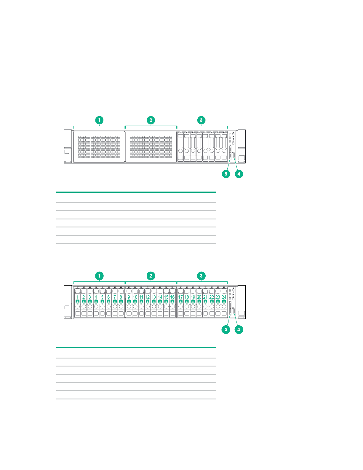
Item
Description
1
Bay 1 (optional drives or universal media bay)
2
Bay 2 (optional drives)
3
Fixed drive bays
4
Front USB 3.0 connector
5
Serial label pull tab
Item
Description
1
Bay 1
2
Bay 2
3
Bay 3, fixed drive bay
4
Front USB 3.0 connector
5
Serial label pull tab
Front panel components
• SFF model (8-drive)
• SFF model (24-drive)
Component identification 7
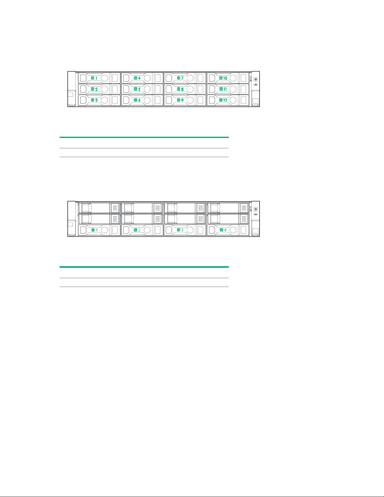
• LFF model (12-drive)
Item
Description
1-12
Drive bays
Item
Description
1-4
Drive bays
• LFF model (4-drive)
Component identification 8

Front panel LEDs and buttons
Item
Description
Status
Power On/Standby button
Solid green = System on
Health LED*
Solid green = Normal
NIC status LED*
Solid green = Link to network
UID button/LED*
Solid blue = Activated
•
•
•
• SFF front panel LEDs and button
1
2
3
4
and system power LED*
Flashing green (1 Hz/cycle per sec) = Performing power on
sequence
Solid amber = System in standby
Off = No power present**
Flashing green (1 Hz/cycle per sec) = iLO is rebooting
Flashing amber = System degraded
Flashing red (1 Hz/cycle per sec) = System critical†
Flashing green (1 Hz/cycle per sec) = Network active
Off = No network activity
Flashing blue:
1 Hz/cycle per sec = Remote management or firmware upgrade
in progress
4 Hz/cycle per sec = iLO manual reboot sequence initiated
8 Hz/cycle per sec = iLO manual reboot sequence in progress
*When all four LEDs described in this table flash simultaneously, a power fault has occurred. For more information,
see "Power fault LEDs (on page 11)."
**Facility power is not present, power cord is not attached, no power supplies are installed, power supply failure has
occurred, or the power button cable is disconnected.
†If the health LED indicates a degraded or critical state, review the system IML or use iLO to review the system health
status.
Off = Deactivated
Component identification 9

• LFF LEDs and button
Item
Description
Status
Health LED*
Solid green = Normal
Power On/Standby button
Solid green = System on
NIC status LED*
Solid green = Link to network
UID button/LED*
Solid blue = Activated
•
•
•
1
Flashing green (1 Hz/cycle per sec) = iLO is rebooting
Flashing amber = System degraded
Flashing red (1 Hz/cycle per sec) = System critical**
2
and system power LED*
Flashing green (1 Hz/cycle per sec) = Performing power on
sequence
Solid amber = System in standby
Off = No power present†
3
Flashing green (1 Hz/cycle per sec) = Network active
Off = No network activity
4
Flashing blue:
1 Hz/cycle per sec = Remote management or firmware upgrade
in progress
4 Hz/cycle per sec = iLO manual reboot sequence initiated
8 Hz/cycle per sec = iLO manual reboot sequence in progress
*When all four LEDs described in this table flash simultaneously, a power fault has occurred. For more information,
see "Power fault LEDs (on page 11)."
**If the health LED indicates a degraded or critical state, review the system IML or use iLO to review the system health
status.
†Facility power is not present, power cord is not attached, no power supplies are installed, power supply failure has
occurred, or the power button cable is disconnected.
Off = Deactivated
UID button functionality
The UID button can be used to display the HPE ProLiant Pre-boot Health Summary when the server will
not power on. For more information, see the HPE iLO 4 User Guide on the Hewlett Packard Enterprise
website (http://www.hpe.com/info/ilo/docs).
Component identification 10
Power fault LEDs
Subsystem
LED behavior
1 flash
Processor
2 flashes
Memory
3 flashes
Riser board PCIe slots
4 flashes
FlexibleLOM
5 flashes
controller/Smart SAS HBA controller
6 flashes
System board PCIe slots
7 flashes
Power backplane or storage backplane
8 flashes
Power supply
9 flashes
The following table provides a list of power fault LEDs, and the subsystems that are affected. Not all
power faults are used by all servers.
System board
Removable HPE Flexible Smart Array
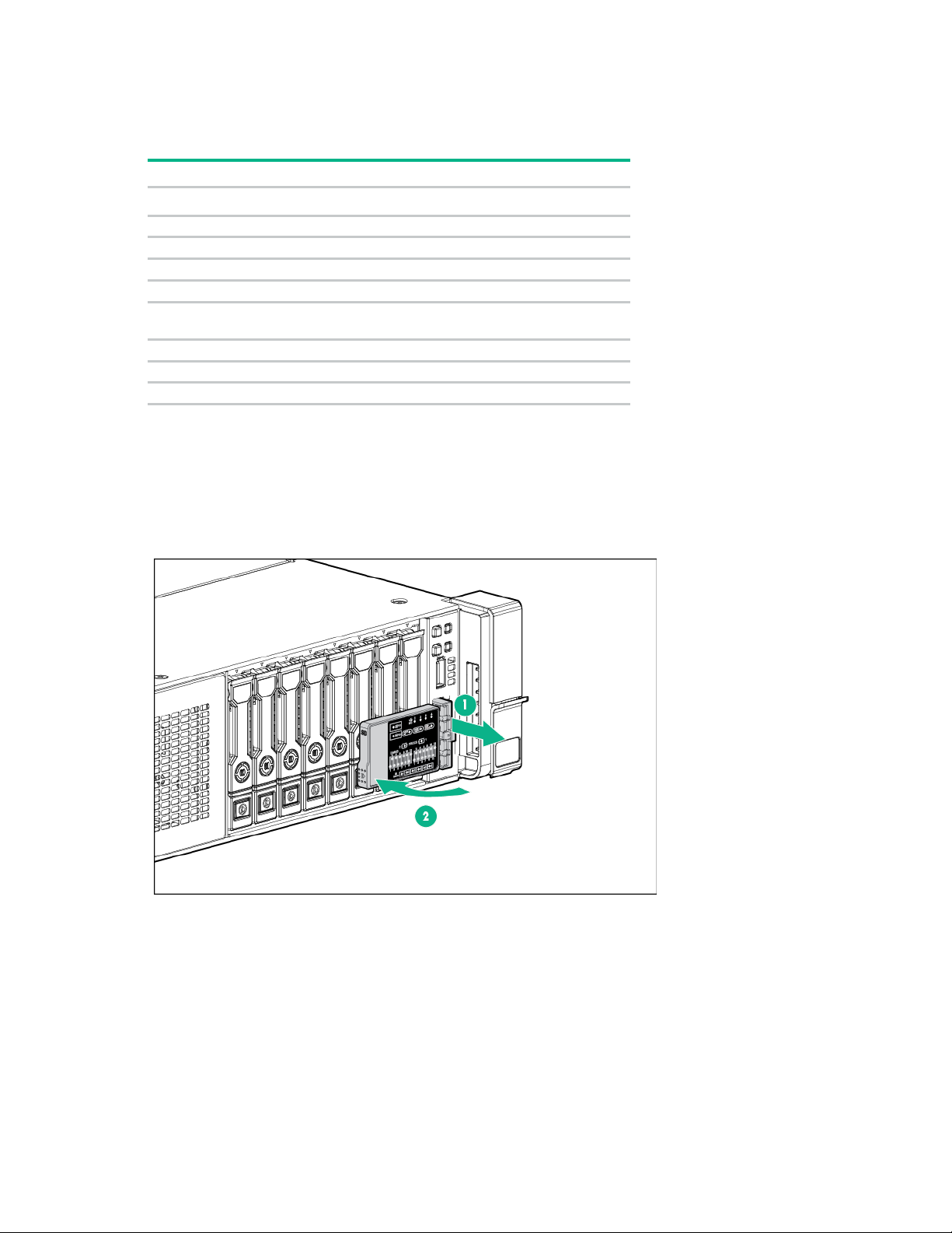
Access the optional HPE Systems Insight Display
To access a pop-out HPE Systems Insight Display on models with this option installed:
1. Press and release the panel.
2. After the display fully ejects, rotate the display to view the LEDs.
Component identification 11
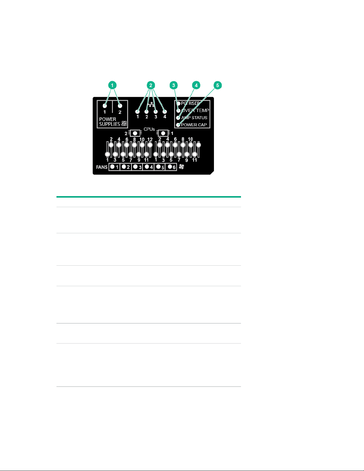
Systems Insight Display LEDs
Item
Description
Status
Power supplies
Off = Normal
NIC link/activity
Off = No link to network. If the power is off,
Over temp
Off = Normal
AMP status
Off = AMP modes disabled
Power cap
Off = System is in standby, or no cap is
All other LEDs
Off = Normal
The Systems Insight Display LEDs represent the system board layout. The display enables diagnosis with
the access panel installed.
1
2
3
4
5
—
Solid amber = Power subsystem
degraded, power supply failure, or input
power lost.
view the rear panel RJ-45 LEDs for status
("Rear panel LEDs" on page 14).
Flashing green = Network link and activity
Solid green = Network link
Solid amber = High system temperature
detected
Solid green = AMP mode enabled
Solid amber = Failover
Flashing amber = Invalid configuration
set.
Solid green = Power cap applied
Amber = Failure
For more information on the activation of
these LEDs, see "Systems Insight Display
LED combinations (on page 13)."
Component identification 12

Systems Insight Display LED combinations
color
Red
Amber
One or more of the following conditions may
•
•
•
•
Amber
Green
Processor in socket X is in a pre-failure
DIMM (amber)
Red
Green
One or more DIMMs have failed.
DIMM (amber)
Amber
Green
DIMM in slot X is in a pre-failure condition.
Amber
Green
The Health Driver has detected a cautionary
Red
Amber
The server has detected a hardware critical
PCI riser (amber)
Red
Green
The PCI riser cage is not seated properly.
Fan (amber)
Amber
Green
One fan has failed or has been removed.
Red
Green
Two or more fans have failed or been
Red
Amber
One or more of the following conditions may
•
•
•
Amber
Green
One or more of the following conditions may
•
•
•
•
Power cap (off)
—
Amber
Standby
Power cap (green)
—
Flashing green
Waiting for power
Power cap (green)
—
Green
Power is available.
amber)
—
Amber
Power is not available.
When the health LED on the front panel illuminates either amber or red, the server is experiencing a
health event. Combinations of illuminated Systems Insight Display LEDs, the system power LED, and the
health LED indicate system status.
Systems Insight
Display LED and
Health LED
System power
LED
Status
Processor (amber)
Processor (amber)
Over temp (amber)
Over temp (amber)
Fan (amber)
Power supply (amber)
Power supply (amber)
exist:
Processor in socket X has failed.
Processor X is not installed in the
socket.
Processor X is unsupported.
ROM detects a failed processor during
POST.
condition.
temperature level.
temperature level.
removed.
exist:
Only one power supply is installed and
that power supply is in standby.
Power supply fault
System board fault
exist:
Redundant power supply is installed
and only one power supply is functional.
AC power cord is not plugged into
redundant power supply.
Redundant power supply fault
Power supply mismatch at POST or
power supply mismatch through
hot-plug addition
Power cap (flashing
IMPORTANT: If more than one DIMM slot LED is illuminated, further troubleshooting is
required. Test each bank of DIMMs by removing all other DIMMs. Isolate the failed DIMM by
replacing each DIMM in a bank with a known working DIMM.
Component identification 13
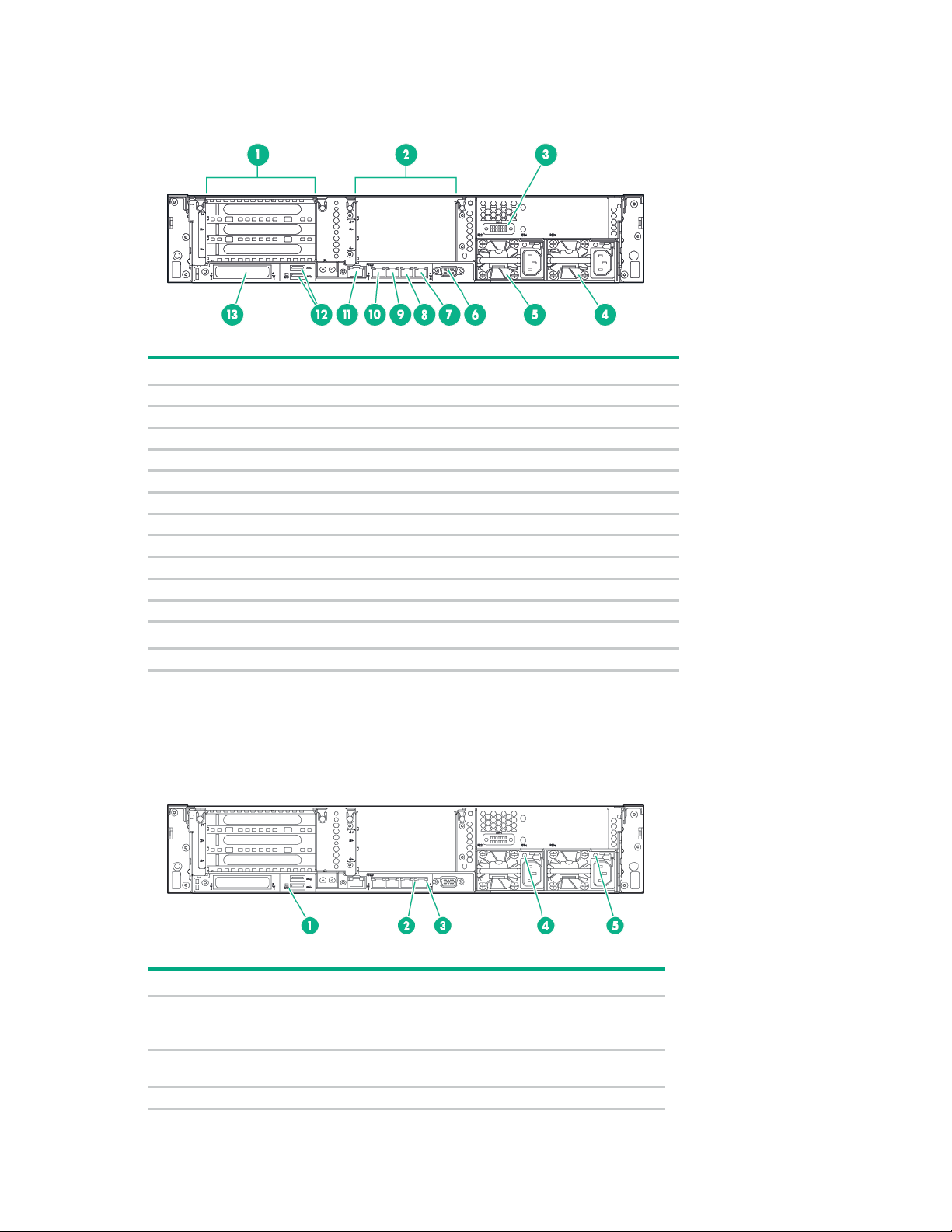
Rear panel components
Item
Description
1
PCIe slots 1–3 (top to bottom)
2
Optional PCIe slots 4–6 (top to bottom)*
3
Optional serial port
4
Power supply 1 (PS1)
5
Power supply 2 (PS2)
6
Video connector
7
1Gb RJ-45 port 4
8
1Gb RJ-45 port 3
9
1Gb RJ-45 port 2
10
1Gb RJ-45 port 1
11
iLO connector
USB 3.0 connectors
13
FlexibleLOM option
Item
Description
Status
UID LED
Off = Deactivated
NIC link LED
Off = No network link
3
NIC activity LED
Off = No network activity
12
*Requires second processor
Rear panel LEDs
1
2
Solid blue = Activated
Flashing blue = System being managed remotely
Green = Network link
Component identification 14
Item
Description
Status
Solid green = Link to network
Flashing green = Network activity
Power supply 2
Off = System is off or power supply has failed.
Power supply 1
Off = System is off or power supply has failed.
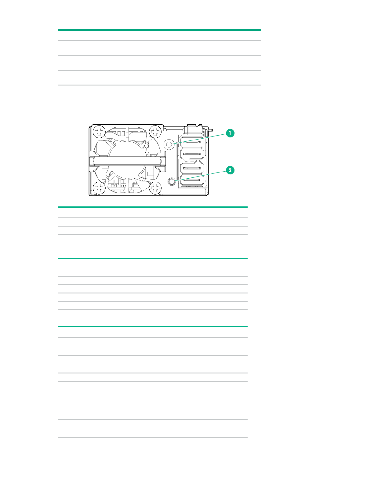
Item
Description
1
FSBBU module LED
2
Battery check button
0
< 5
1
<= 30
2
31 – 69
3
>= 70
•
•
•
•
Solid amber
Online mode and charger is ON
•
•
•
•
•
4
5
LED
LED
Solid green = Normal
Solid green = Normal
Flex slot battery backup module LEDs and buttons
When the battery check button is pressed, the LED indicates the state of the battery. The number of times
that the LED flashes indicates the state of charge.
# of LED
State of charge (%)
flashes
The state of the LED indicates the FSBBU operating mode.
LED Mode/State
Off
Flashing amber
Ship/storage mode
Cycle power operating
Battery diagnostic
Active mode
Flashing green Discharge mode
Solid green
RSOC—70-100% frequency=0.5Hz; duty=0.5
RSOC—31-69% frequency=1Hz; duty=0.5
RSOC—0-30% frequency=1.5Hz; duty=0.5
Online mode and charger is OFF
Battery is fully charged
Component identification 15
LED
Mode/State
Flashing red
Auxiliary path A/B protection
Solid red
FSBBU fault or other protections
For more information about the FSBBU module, see "750 W Flex Slot Hot Plug Battery Backup Module
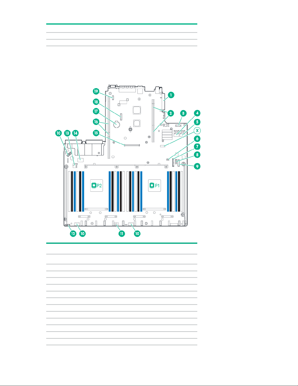
FlexibleLOM connector
2
Primary (processor 1) PCI riser connector
3
Optical front VGA/USB 2.0 connector
4
x4 SATA port 1
5
x4 SATA port 2
6
Backplane presence detect connector
7
Optical/SATA port 5
8
SATA port 4
9
Front power/USB 3.0 connector
10
Drive backplane power connector
11
HPE Smart Storage Battery connector
12
Optional Location Discovery Services connector
13
MicroSD card slot
(on page 134)."
System board components
Item Description
1
Component identification 16
Item Description
14
Dual internal USB 3.0 connector
15
Smart Array/HBA connector
16
Secondary processor (processor 2) PCI riser connector
17
System battery
18
TPM connector
19
Optional serial port connector
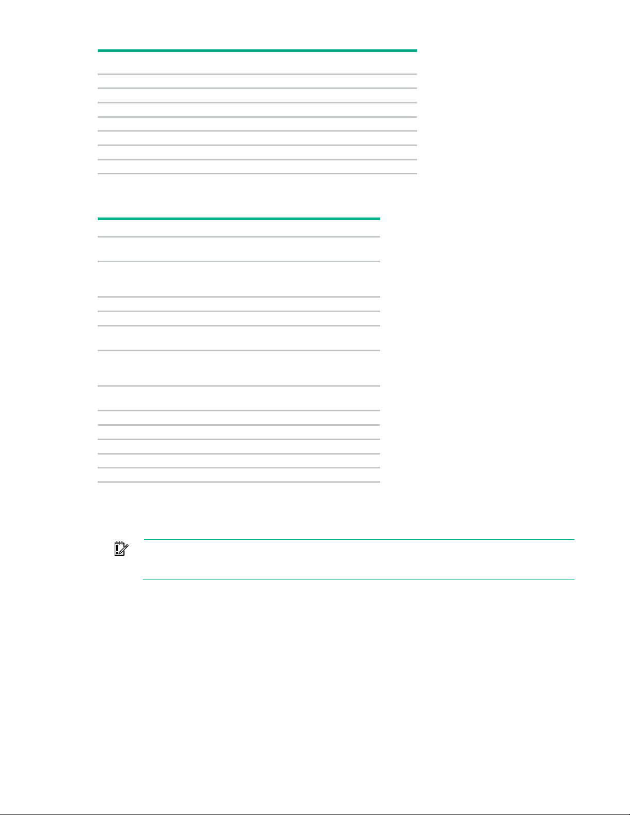
X
System maintenance switch
Off
Off = iLO security is enabled.
Off
Off = System configuration can be
S3
Off
Reserved
S4
Off
Reserved
Off
Off = Power-on password is enabled.
Off
Off = No function
Off
Off = Set default boot mode to UEFI.
S8
—
Reserved
S9
—
Reserved
S10
—
Reserved
S11
—
Reserved
S12
—
Reserved
Before using the S7 switch to change to Legacy BIOS Boot Mode, be sure the
HPE Dynamic Smart Array B140i Controller is disabled. Do not use the B140i controller when
System maintenance switch
Position Default Function
S1
S2
S5
S6
S7
On = iLO security is disabled.
changed.
On = System configuration is locked.
On = Power-on password is disabled.
On = ROM reads system
configuration as invalid.
On = Set default boot mode to legacy.
You can access the redundant ROM by setting S1, S5, and S6 to On.
When system maintenance switch S6 is set to the On position, the system is prepared to erase all system
configuration settings from both CMOS and NVRAM.
IMPORTANT:
the server is in Legacy BIOS Boot Mode.
NMI functionality
An NMI crash dump enables administrators to create crash dump files when a system is hung and not
responding to traditional debug mechanisms.
Crash dump log analysis is an essential part of diagnosing reliability problems, such as hangs in operating
systems, device drivers, and applications. Many crashes freeze a system, and the only available action
for administrators is to cycle the system power. Resetting the system erases any information that could
support problem analysis, but the NMI feature preserves that information by performing a memory dump
before a hard reset.
Component identification 17
To force the OS to invoke the NMI handler and generate a crash dump log, the administrator can use the
•
•
2
Reserved
iLO Virtual NMI feature.
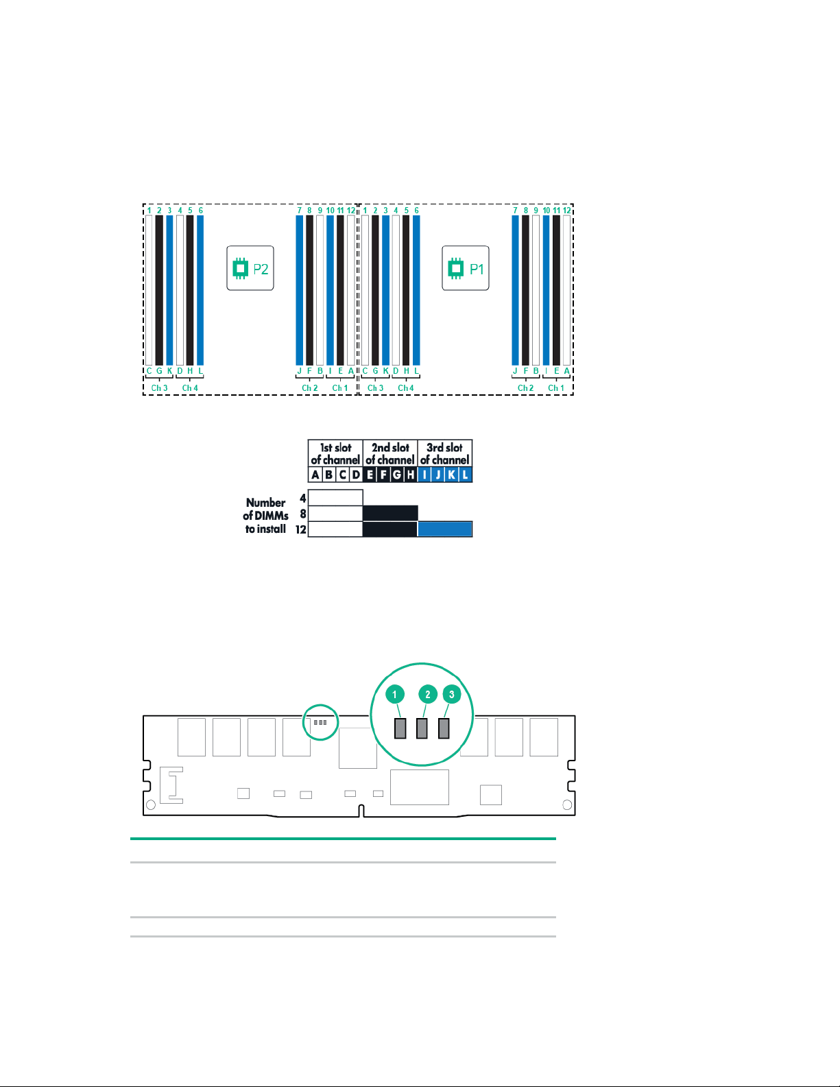
DIMM slot locations
DIMM slots are numbered sequentially (1 through 12) for each processor. The supported AMP modes use
the letter assignments for population guidelines.
NVDIMM LEDs
When the server boots up, all LEDs flash three times. Any LED activity not described in this section
indicates a possible error.
Item LED definitions
1
Fast-flashing blue = A backup is in progress. Do not remove the
NVDIMM.
Slow-flashing blue (1 flash/15 seconds) = Normal operation.
Component identification 18
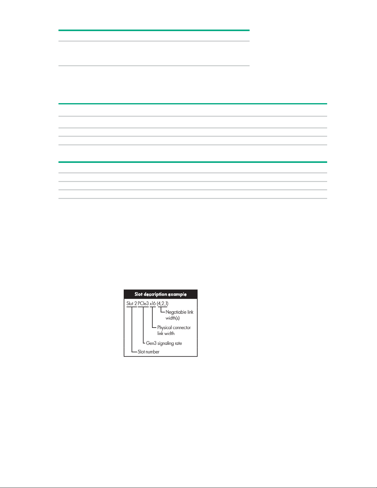
Item
LED definitions
•
•
PCIe3 x16 (8,4,2,1)
—
2 - HL/FH
PCIe3 x16 (8,4,2,1)
PCIe3 x16 (16,8,4,2,1)
3 - HL/FH
PCIe3 x8 (8,4,2,1)
PCIe3 x8 (8,4,2,1)
PCIe 3-slot riser cage*
4 - FL/FH
PCIe3 x16 (16,8,4,2,1)
5 - HL/FH
PCIe3 x16 (16,8,4,2,1)
6 - HL/FH
PCIe3 x8 (8,4,2,1)
3
Solid or flashing green = Power is available to the NVDIMM. Do not
remove the NVDIMM.
Off = Power is not available to the NVDIMM.
Non-hot-plug PCI riser board slot definitions
• Primary riser cage connector, connected to processor 1
PCIe 3-slot riser cage* Optional PCIe 2-slot x16 riser cage
1 - FL/FH
• Secondary riser cage connector, connected to processor 2 (processor 2 must be installed)
*The server ships with one PCIe3 riser cage installed in the primary riser cage connector.
Notes:
• "Primary" denotes the riser cage is installed in the primary riser connector.
• "Secondary" denotes the riser cage is installed in the secondary riser connector.
• Installing the riser cages listed in the table above in either the primary or secondary riser connectors
determines the form factor of the PCI expansion boards supported by those riser cages.
• FL/FH denotes full-length, full-height. HL/FH denotes half-length, full-height.
Component identification 19
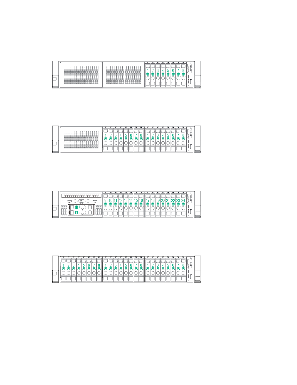
SAS and SATA device numbers
• 8SFF device bay numbering
• Optional 16SFF device bay numbering
• Optional 16SFF device bay numbering with SAS expander solution used
• Optional 24SFF device bay numbering
Component identification 20
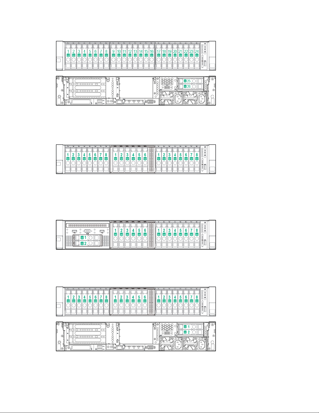
• Optional 24SFF device bay numbering with SAS expander solution used
• 6SFF NVMe Express Bay Enablement Option device numbering with 8SFF drive cage installed in
bay 1
• 6SFF NVMe Express Bay Enablement Option device numbering with 2SFF drive cage installed in
universal media bay 1
• 6SFF NVMe Express Bay Enablement Option device numbering with 2SFF drives installed at the
rear of the server
Component identification 21
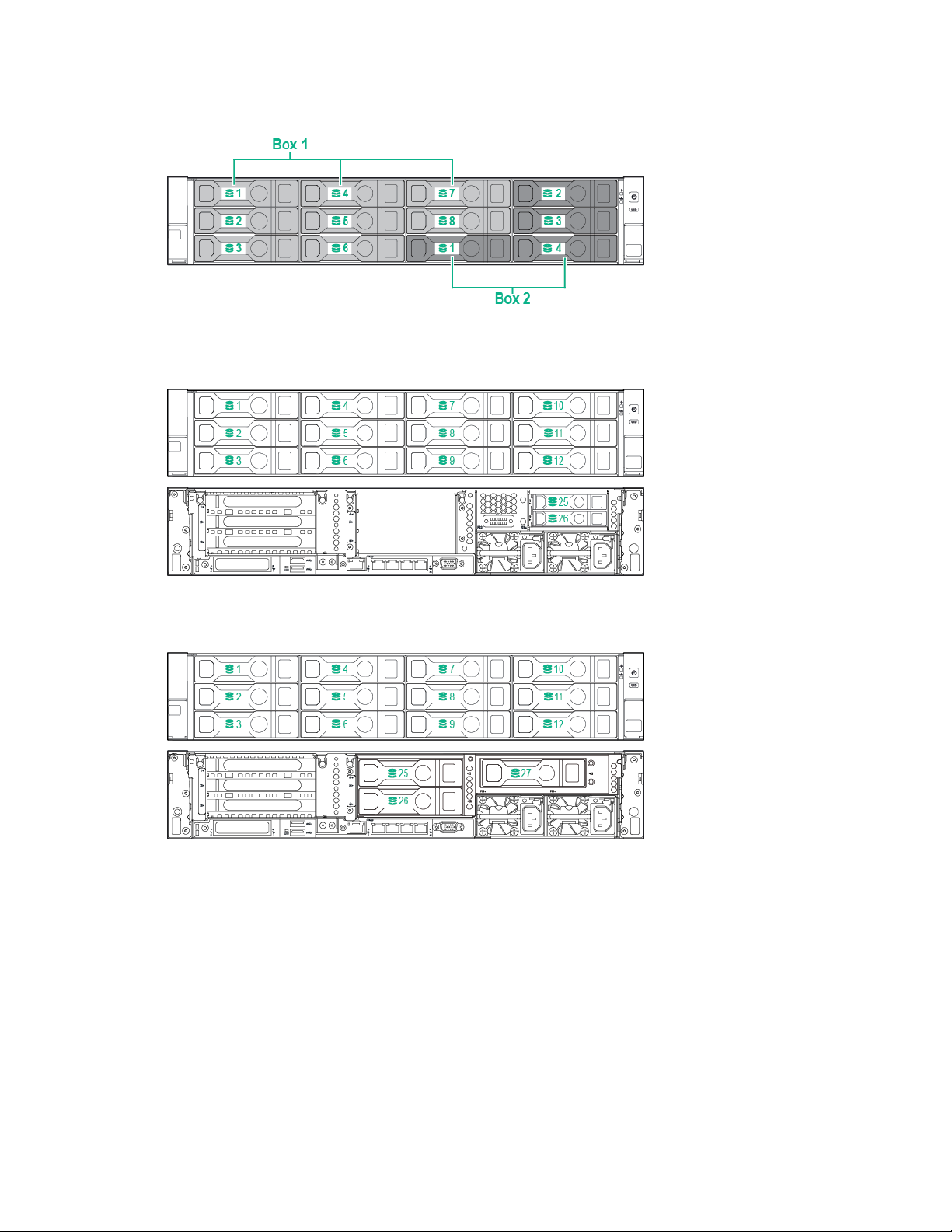
• 12LFF device bay numbering
• 12LFF device bay numbering with 2-bay rear SAS expander solution used
• 12LFF device bay numbering with 3-bay rear SAS expander solution used
Component identification 22
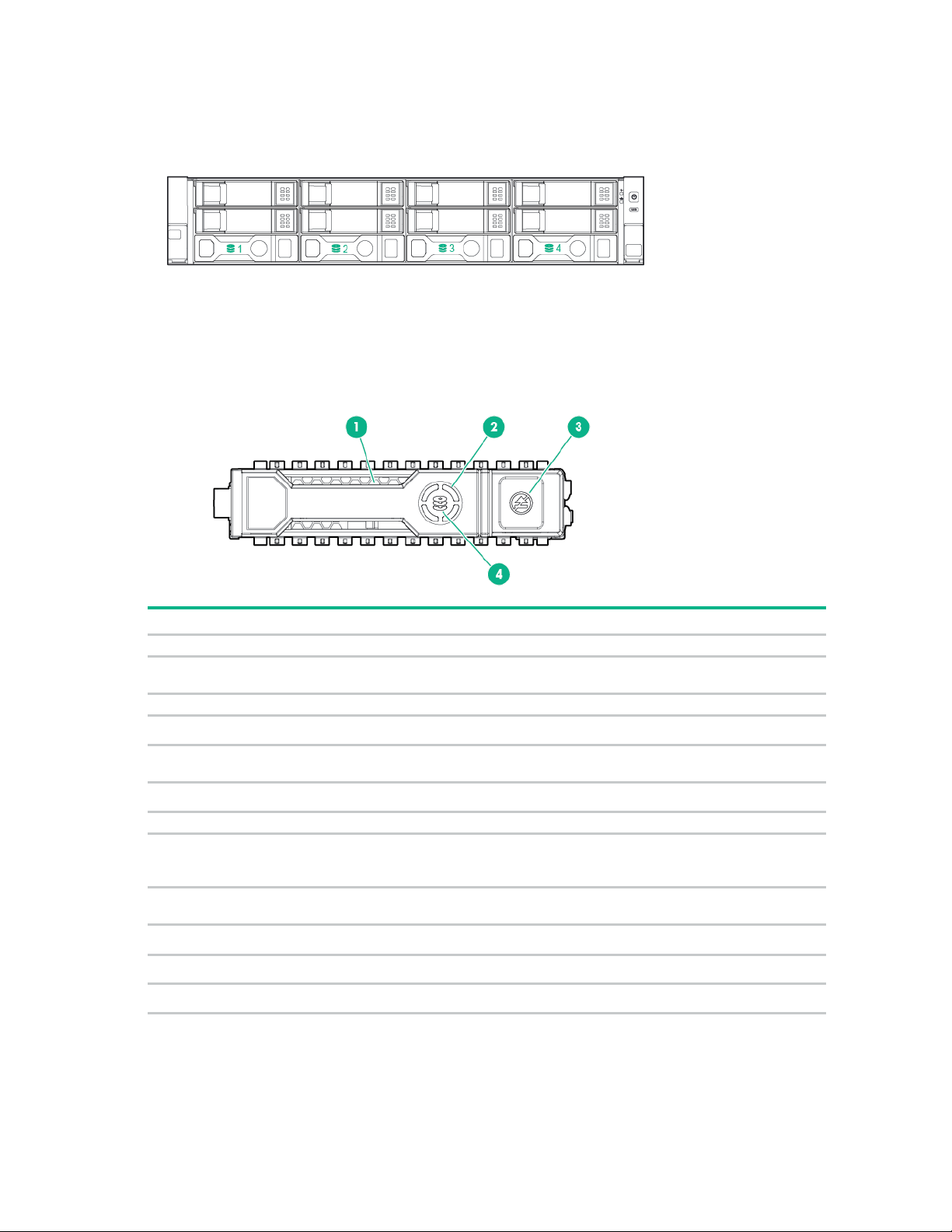
• 4LFF device bay numbering
Item
LED
Status
Definition
1
Locate
Solid blue
The drive is being identified by a host application.
Flashing blue
The drive carrier firmware is being updated or requires an
2
Activity ring
Rotating green
Drive activity.
Off
No drive activity.
Do not remove
Solid white
Do not remove the drive. Removing the drive causes one or
Off
Removing the drive does not cause a logical drive to fail.
4
Drive status
Solid green
The drive is a member of one or more logical drives.
Flashing green
The drive is rebuilding or performing a RAID migration, strip size
Flashing
The drive is a member of one or more logical drives and predicts
Flashing amber
The drive is not configured and predicts the drive will fail.
Solid amber
The drive has failed.
Off
The drive is not configured by a RAID controller.
Hot-plug drive LED definitions
3
update.
more of the logical drives to fail.
amber/green
migration, capacity expansion, or logical drive extension, or is
erasing.
the drive will fail.
Component identification 23
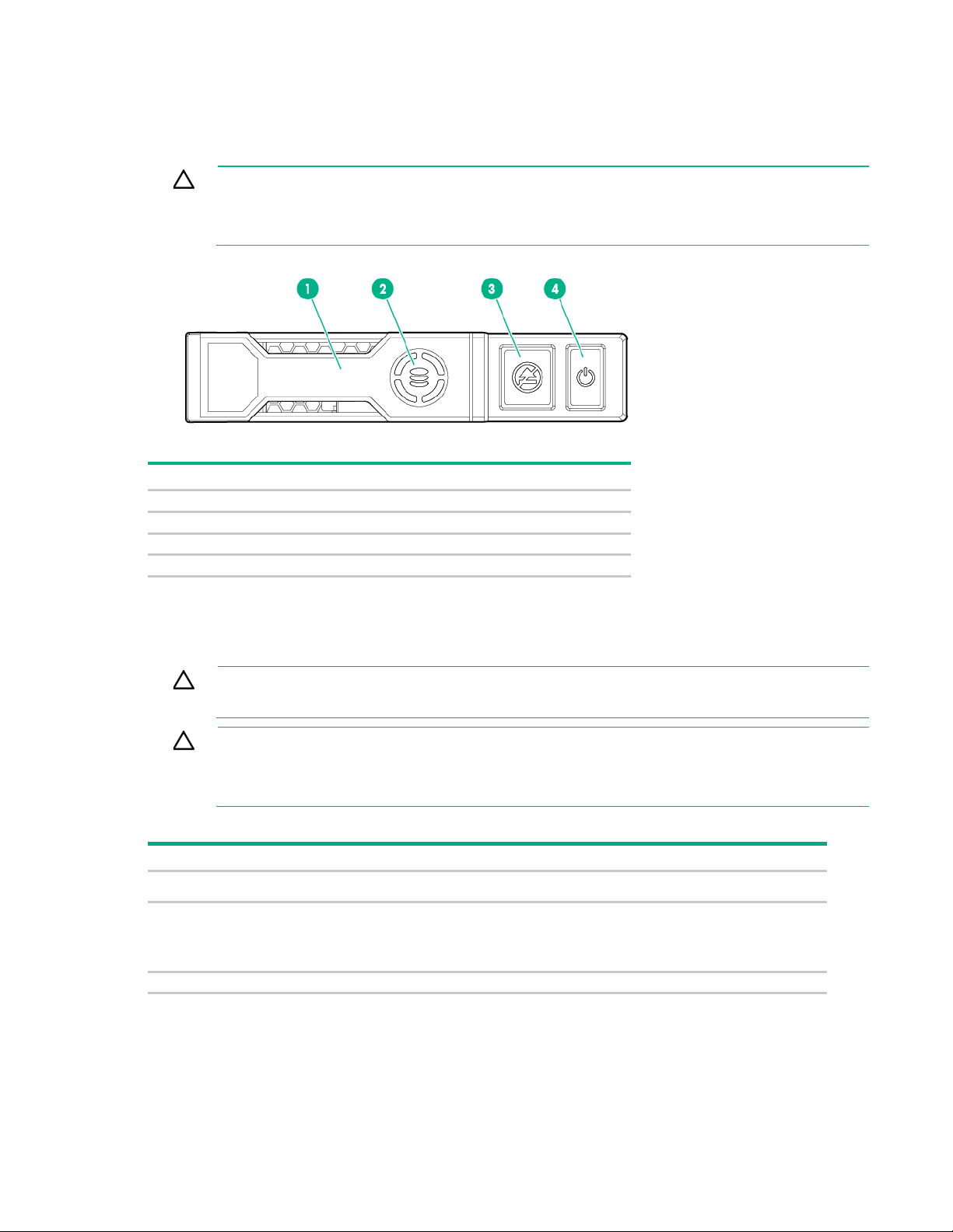
NVMe SSD components
button LED is flashing. The Do Not Remove button LED flashes to indicate the device is still in
Item
Description
1
Release lever
2
Activity ring
3
Do Not Remove button
4
Power button
To avoid damage to server components, fan blanks must be installed in fan bays
Configuration
Fan bay 1
Fan bay 2
Fan bay 3
Fan bay 4
Fan bay 5
Fan bay 6
Fan blank
Fan blank
Fan
Fan
Fan
Fan
fans
Fan
Fan
Fan
Fan
Fan
Fan
2 processors
Fan
Fan
Fan
Fan
Fan
Fan
The NVMe SSD is a PCIe bus device. A device attached to a PCIe bus cannot be removed without
allowing the device and bus to complete and cease the signal/traffic flow.
CAUTION: Do not remove an NVMe SSD from the drive bay while the Do Not Remove
use. Removal of the NVMe SSD before the device has completed and ceased signal/traffic
flow can cause loss of data.
Hot-plug fans
CAUTION:
1 and 2 in a single-processor configuration.
CAUTION: To avoid damage to the equipment, do not operate the server for extended
periods of time if the server does not have the optimal number of fans installed. Although the
server might boot, Hewlett Packard Enterprise does not recommend operating the server
Valid fan configurations are listed in the following table.
1 processor
without the required fans installed and operating.
1 processor, 24 SFF or
12 LFF configuration
with high-performance
Component identification 24
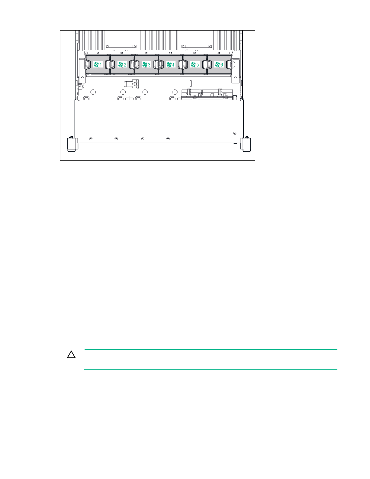
For a single-processor configuration, excluding 24-SFF and 12-LFF configurations, four fans and two
blanks are required in specific fan bays for redundancy. A fan failure or missing fan causes a loss of
redundancy. A second fan failure or missing fan causes an orderly shutdown of the server.
For a dual-processor configuration or single-processor 24-SFF or 12-LFF configurations, six fans are
required for redundancy. A fan failure or missing fan causes a loss of redundancy. A second fan failure or
missing fan causes an orderly shutdown of the server.
The high-performance fans are used for 24-SFF and 12-LFF drive configurations and might be necessary
for the following installations:
• Optional GPU riser installations
• ASHRAE compliant configurations
For more information, see the Hewlett Packard Enterprise website
(http://www.hpe.com/servers/ASHRAE).
The server supports variable fan speeds. The fans operate at minimum speed until a temperature change
requires a fan speed increase to cool the server. The server shuts down during the following
temperature-related scenarios:
• At POST and in the OS, iLO performs an orderly shutdown if a cautionary temperature level is
detected. If the server hardware detects a critical temperature level before an orderly shutdown
occurs, the server performs an immediate shutdown.
• When the Thermal Shutdown feature is disabled in the BIOS/Platform Configuration (RBSU), iLO
does not perform an orderly shutdown when a cautionary temperature level is detected. Disabling
this feature does not disable the server hardware from performing an immediate shutdown when a
critical temperature level is detected.
CAUTION: A thermal event can damage server components when the Thermal Shutdown
feature is disabled in the BIOS/Platform Configuration (RBSU).
Component identification 25
Operations
To reduce the risk of personal injury or equipment damage, be sure that the rack
Powering up the server
To power up the server, press the Power On/Standby button.
Power down the server
Before powering down the server for any upgrade or maintenance procedures, perform a backup of
critical server data and programs.
IMPORTANT: When the server is in standby mode, auxiliary power is still being provided to
the system.
To power down the server, use one of the following methods:
• Press and release the Power On/Standby button.
This method initiates a controlled shutdown of applications and the OS before the server enters
standby mode.
• Press and hold the Power On/Standby button for more than 4 seconds to force the server to enter
standby mode.
This method forces the server to enter standby mode without properly exiting applications and the
OS. If an application stops responding, you can use this method to force a shutdown.
• Use a virtual power button selection through iLO.
This method initiates a controlled remote shutdown of applications and the OS before the server
enters standby mode.
Before proceeding, verify that the server is in standby mode by observing that the system power LED is
amber.
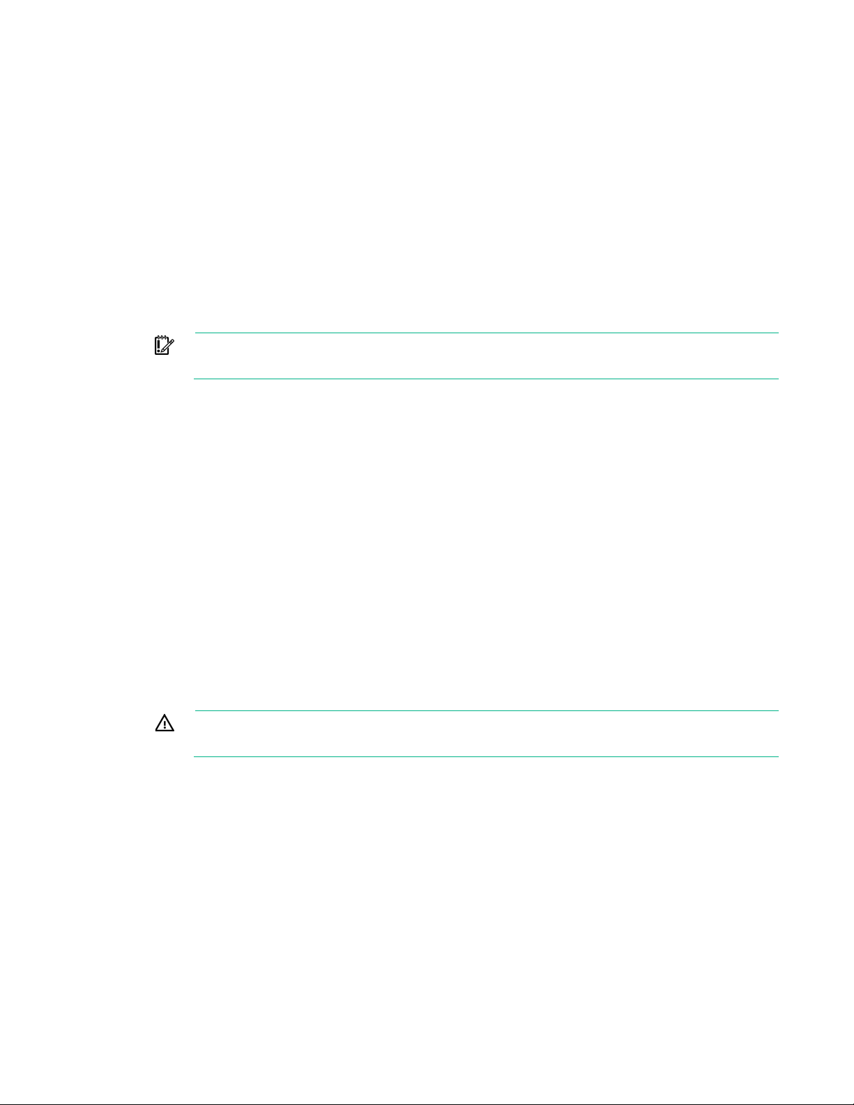
Extend the server from the rack
WARNING:
is adequately stabilized before extending a component from the rack.
1. Pull down the quick release levers on each side of the server.
Operations 26
removed. Operating the server in this manner results in improper airflow and improper cooling
2.
Extend the server from the rack.
3. After performing the installation or maintenance procedure, slide the server back into the rack, and
then press the server firmly into the rack to secure it in place.
WARNING: To reduce the risk of personal injury, be careful when pressing the server
rail-release latches and sliding the server into the rack. The sliding rails could pinch your
fingers.
Remove the server from the rack
To remove the server from a Hewlett Packard Enterprise, Compaq-branded, Telco, or third-party rack:
1. Power down the server (on page 26).
2. Extend the server from the rack (on page 26).
3. Disconnect the cabling and remove the server from the rack. For more information, see the
documentation that ships with the rack mounting option.
4. Place the server on a sturdy, level surface.
Remove the access panel
WARNING: To reduce the risk of personal injury from hot surfaces, allow the drives and the
internal system components to cool before touching them.
CAUTION: Do not operate the server for long periods with the access panel open or
To remove the component:
1. Power down the server (on page 26).
2. Extend the server from the rack (on page 26).
3. Open or unlock the locking latch, slide the access panel to the rear of the chassis, and remove the
that can lead to thermal damage.
access panel.
Operations 27
Install the access panel
1. Place the access panel on top of the server with the hood latch open. Allow the panel to extend past
the rear of the server approximately 1.25 cm (0.5 in).
2. Push down on the hood latch. The access panel slides to a closed position.
3. Tighten the security screw on the hood latch.
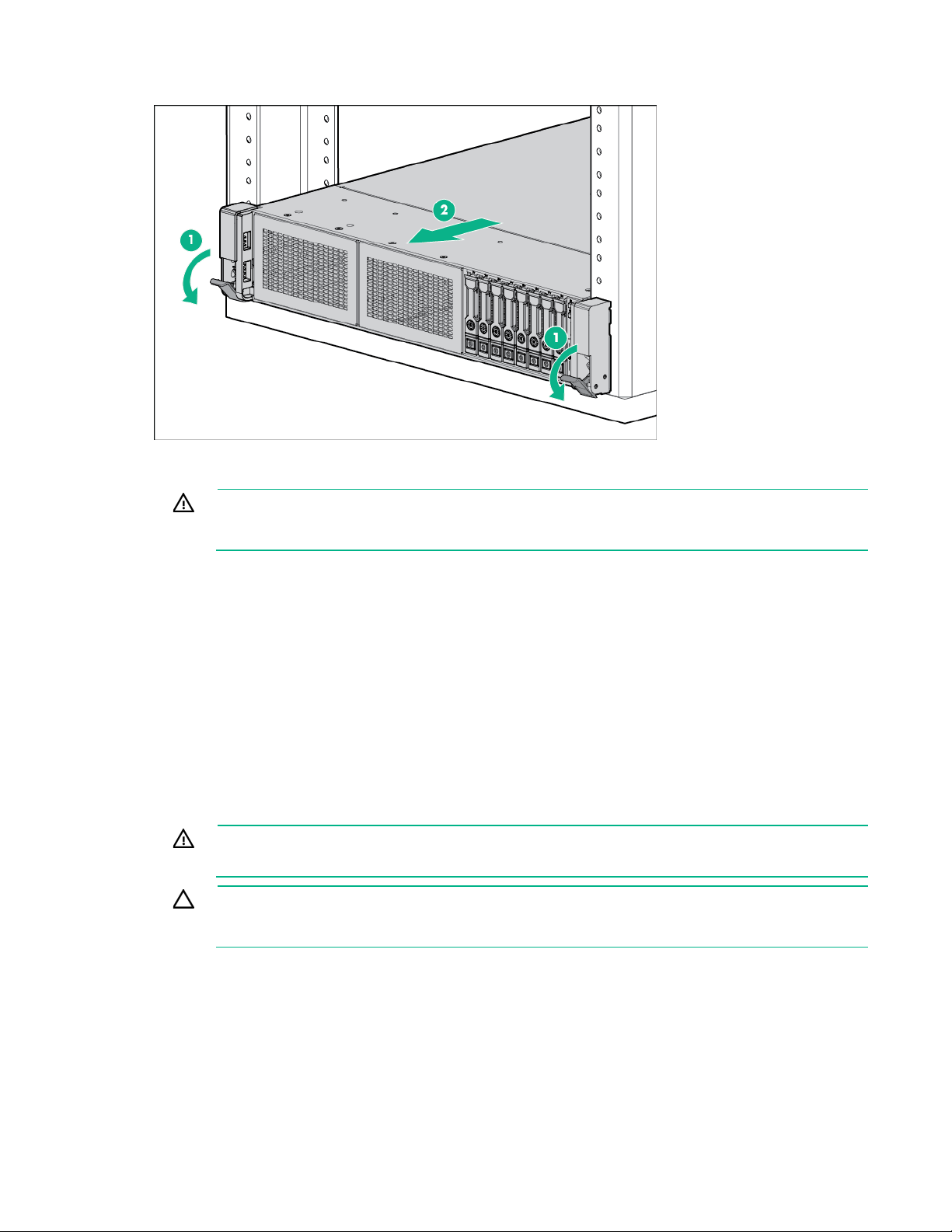
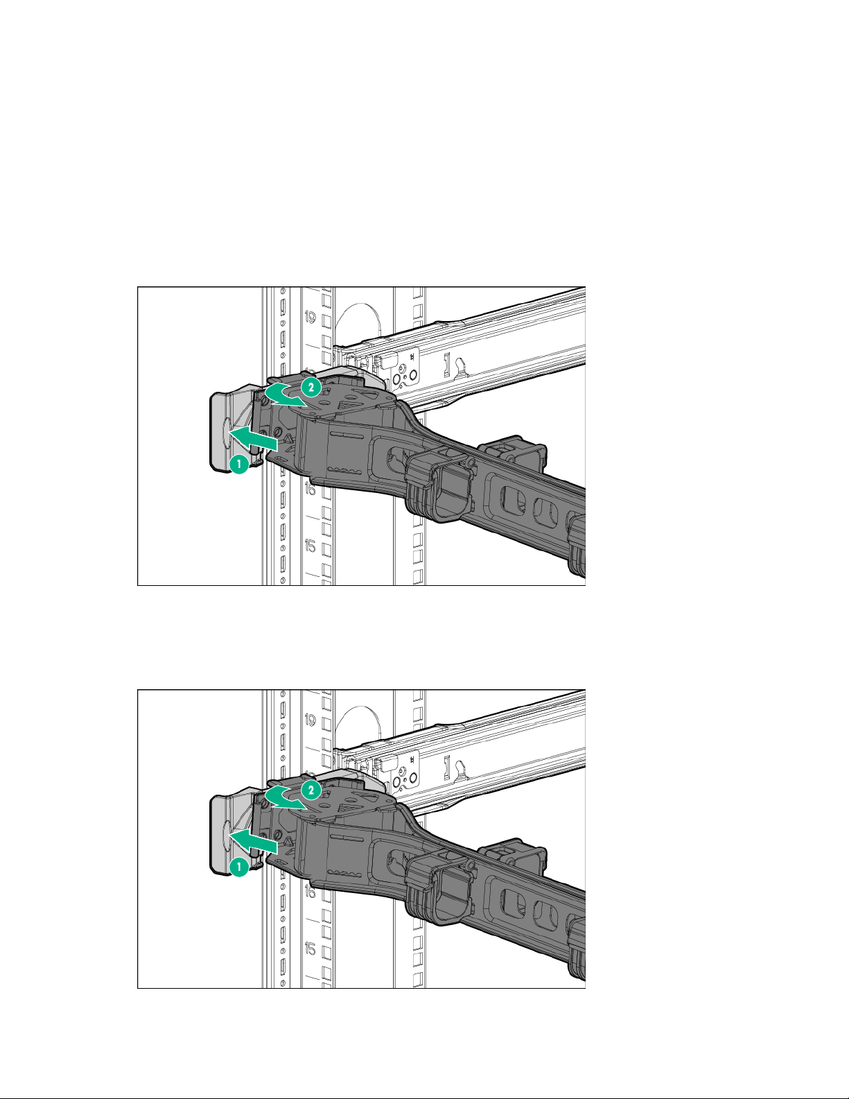
Access the product rear panel
To access the product rear panel, release the cable management arm and swing the arm away from the
rack as indicated.
Opening the cable management arm
To access the server rear panel:
1. Release the cable management arm.
Operations 28
2.
Open the cable management arm. The cable management arm can be right-mounted or
left-mounted.
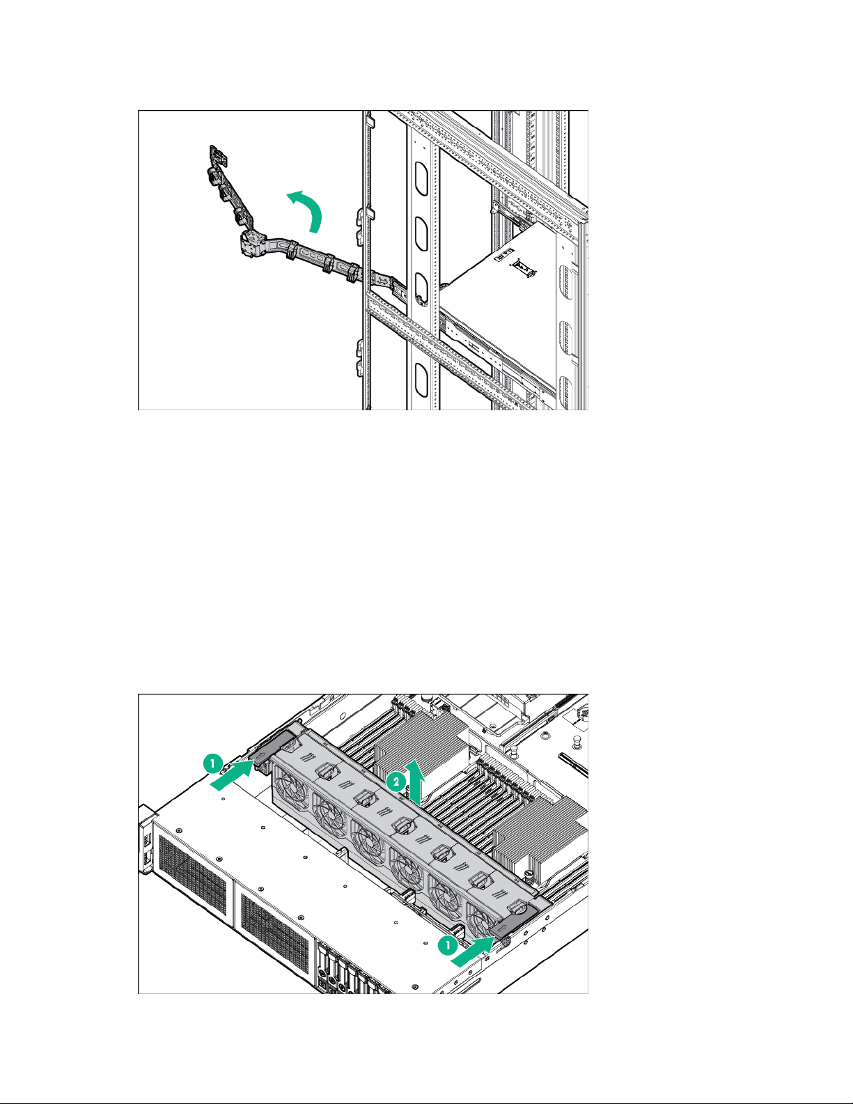
Remove the fan cage
To remove the component:
1. Power down the server (on page 26).
2. Remove all power:
a. Disconnect each power cord from the power source.
b. Disconnect each power cord from the server.
3. Do one of the following:
o Extend the server from the rack (on page 26).
o Remove the server from the rack (on page 27).
4. Remove the access panel (on page 27).
5. Remove the fan cage.
Operations 29
CAUTION: Do not operate the server for long periods with the access panel open or
removed. Operating the server in this manner results in improper airflow and improper cooling
removed. Operating the server in this manner results in improper airflow and improper cooling
that can lead to thermal damage.
IMPORTANT: For optimum cooling, install fans in all primary fan locations. For more
information, refer to the fan locations table ("Hot-plug fans" on page 24).
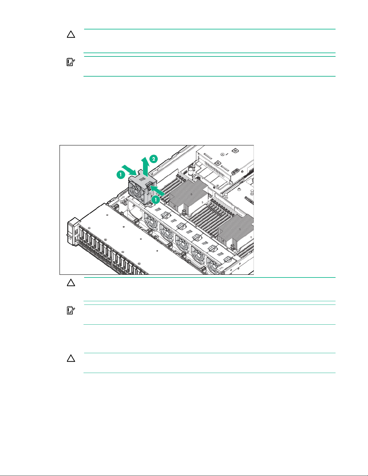
Remove the hot-plug fan
To remove the component:
1. Extend the server from the rack (on page 26).
2. Remove the access panel (on page 27).
3. Remove the fan.
CAUTION: Do not operate the server for long periods with the access panel open or
that can lead to thermal damage.
IMPORTANT: For optimum cooling, install fans in all primary fan locations. For more
information, refer to the fan locations table ("Hot-plug fans" on page 24).
Remove the PCI riser cage
CAUTION: To prevent damage to the server or expansion boards, power down the server
and remove all AC power cords before removing or installing the PCI riser cage.
1. Power down the server (on page 26).
2. Remove all power:
a. Disconnect each power cord from the power source.
b. Disconnect each power cord from the server.
3. Do one of the following:
o Extend the server from the rack (on page 26).
Operations 30
 Loading...