

Page 1

HP ProLiant DL380 Generation 3 Server
User Guide
July 2003 (Third Edition)
Part Number 303130-003
Page 2

© 2003 Hewlett-Packard Development Company, L.P.
Microsoft, MS-DOS, Windows, and Windows NT are trademarks of Microsoft Corporation in the U.S. and
other countries.
Intel and Xeon are trademarks of Intel Corporation in the U.S. and other countries.
Hewlett-Packard Company shall not be liable for technical or editorial errors or omissions contained
herein. The information in this document is provided “as is” without warranty of any kind and is subject to
change without notice. The warranties for HP products are set forth in the express limited warranty
statements accompanying such products. Nothing herein should be construed as constituting an additional
warranty.
July 2003 (Third Edition)
Part Number 303130-003
Audience Assumptions
This guide is for the person who installs, administers, and troubleshoots servers. HP assumes you
are qualified in the servicing of computer equipment and trained in recognizing hazards in
products with hazardous energy levels.
Page 3

3
Contents
Server Component Identification 9
Server Features.....................................................................................................................................9
Front Panel Components....................................................................................................................10
Front Panel LEDs and Buttons........................................................................................................... 11
Rear Panel Components..................................................................................................................... 13
Rear Panel LEDs and Buttons............................................................................................................ 15
System Board Components................................................................................................................ 17
System Maintenance Switch................................................................................................... 18
NMI Switch ............................................................................................................................18
Chassis ID Switch................................................................................................................... 19
DIMM Slots............................................................................................................................ 19
System Board LEDs........................................................................................................................... 20
System LEDs and Internal Health LED Combinations...................................................................... 22
SCSI Backplane Components ............................................................................................................ 24
SCSI Backplane LEDs....................................................................................................................... 25
Hot-Plug SCSI Hard Drive LEDs ......................................................................................................26
Hot-Plug SCSI Hard Drive LED Combinations.................................................................................28
Internal PCI Hot Plug LEDs and Button............................................................................................29
PCI Hot Plug LED Status Combinations ........................................................................................... 30
PCI Riser Cage LED.......................................................................................................................... 31
Remote Management Connector........................................................................................................ 31
Identifying Hot-Plug Fans.................................................................................................................. 32
Hot-Plug Fan LED ............................................................................................................................. 33
Power Converter Module LED .......................................................................................................... 34
Battery-Backed Write Cache Enabler LEDs...................................................................................... 34
Battery-Backed Write Cache Enabler LED Statuses .........................................................................35
Server Operations 37
Powering Up the Server ..................................................................................................................... 37
Powering Down the Server ................................................................................................................ 37
Extending the Server from the Rack ..................................................................................................38
Removing the Access Panel............................................................................................................... 40
Installing the Access Panel ................................................................................................................40
Removing the PCI Riser Cage ........................................................................................................... 40
Installing the PCI Riser Cage............................................................................................................. 42
Page 4

4 HP ProLiant DL380 Generation 3 Server User Guide
Server Setup 45
Optional Installation Services ............................................................................................................ 45
Rack Planning Resources................................................................................................................... 46
Optimum Environment ......................................................................................................................47
Space and Airflow Requirements ...........................................................................................47
Temperature Requirements..................................................................................................... 48
Power Requirements...............................................................................................................49
Electrical Grounding Requirements........................................................................................50
Rack Warnings................................................................................................................................... 50
Identifying the Contents of the Server Shipping Carton .................................................................... 51
Installing Hardware Options ..............................................................................................................52
Installing the Server into the Rack..................................................................................................... 52
Powering Up and Configuring the Server..........................................................................................62
Installing the Operating System......................................................................................................... 63
Registering the Server........................................................................................................................ 63
Hardware Options Installation 65
Introduction........................................................................................................................................ 65
Processor Option................................................................................................................................ 65
Memory Options ................................................................................................................................ 69
Online Spare Memory Configuration .....................................................................................70
DIMM Installation Guidelines................................................................................................ 70
Installing DIMMs ................................................................................................................... 71
Hot-Plug SCSI Hard Drive Options................................................................................................... 72
SCSI IDs................................................................................................................................. 72
Removing a Hard Drive Blank ............................................................................................... 73
Removing a Hot-Plug SCSI Hard Drive................................................................................. 74
Installing a Hot-Plug SCSI Hard Drive ..................................................................................74
Hot-Plug Tape Drive Option.............................................................................................................. 75
Battery-Backed Write Cache Enabler Option .................................................................................... 77
Redundant Hot-Plug Fans .................................................................................................................. 79
Installation Requirements .......................................................................................................81
Identifying Hot-Plug Fans ...................................................................................................... 81
Installing Redundant Hot-Plug Fans.......................................................................................82
Redundant Hot-Plug AC Power Supply Option................................................................................. 84
DC Power Supply Option ..................................................................................................................87
Expansion Board Options ..................................................................................................................91
Removing Expansion Slot Cover 1......................................................................................... 91
Removing Expansion Slot Covers 2 and 3 .............................................................................92
Installing a Non-Hot-Plug Expansion Board .......................................................................... 94
Installing PCI Hot Plug Expansion Boards............................................................................. 95
Server Cabling 99
Hot-Plug SCSI Hard Drive Cabling...................................................................................................99
Page 5

Contents 5
Integrated Simplex SCSI Cabling......................................................................................... 100
Integrated Duplex SCSI Cabling .......................................................................................... 101
PCI Simplex SCSI Cabling................................................................................................... 101
PCI Duplex SCSI Cabling .................................................................................................... 102
Installing the SCSI Terminator Board .................................................................................. 103
Removing the SCSI Terminator Board................................................................................. 104
CD-ROM Drive Cabling.................................................................................................................. 105
Diskette Drive Cabling..................................................................................................................... 106
Power Button/LED Cabling ............................................................................................................. 106
PCI Hot Plug Backplane Cabling..................................................................................................... 107
RILOE II Cabling ............................................................................................................................108
Internal Power Cabling .................................................................................................................... 108
External Storage Cabling ................................................................................................................. 109
Server Configuration and Utilities 111
ROM-Based Setup Utility................................................................................................................ 111
Using RBSU ......................................................................................................................... 112
Auto-Configuration Process ................................................................................................. 116
Boot Options......................................................................................................................... 117
Configuring Online Spare Memory ...................................................................................... 118
Re-Entering the Server Serial Number ................................................................................. 118
Redundant ROM Support................................................................................................................. 119
Safety and Security Benefits................................................................................................. 119
Access to Redundant ROM Settings..................................................................................... 119
ROMPaq Utility ............................................................................................................................... 120
System Online ROM Flash Component Utility ...............................................................................121
USB Support ....................................................................................................................................121
SmartStart Software ......................................................................................................................... 122
SmartStart Autorun Menu..................................................................................................... 122
SmartStart Scripting Toolkit................................................................................................. 123
Enterprise Diagnostics LX32 Utility ....................................................................................124
Drivers .............................................................................................................................................124
Option ROM Configuration for Arrays............................................................................................ 124
Management Agents ........................................................................................................................125
Insight Manager 7 ............................................................................................................................ 125
Automatic Server Recovery-2.......................................................................................................... 126
Survey Utility................................................................................................................................... 126
Integrated Management Log ............................................................................................................ 126
Server Specific Troubleshooting 129
Minimum Hardware Configuration..................................................................................................129
Server Error Messages ..................................................................................................................... 130
When the Server Does Not Start...................................................................................................... 130
Page 6

6 HP ProLiant DL380 Generation 3 Server User Guide
Diagnostic Steps............................................................................................................................... 132
Is the System Power LED Amber?....................................................................................... 134
Is the System Power LED Green? ........................................................................................ 135
Is the External Health LED Green? ...................................................................................... 135
Is the Internal Health LED Green? ....................................................................................... 136
Is the Monitor Displaying Information? ............................................................................... 137
Problems After Initial Boot.............................................................................................................. 137
System Cannot Load SmartStart........................................................................................... 138
SmartStart Fails During Installation ..................................................................................... 138
SmartStart Cannot Load Operating System.......................................................................... 139
ROMPaq Disaster Recovery ............................................................................................................ 139
Other Information Resources........................................................................................................... 140
Battery Replacement 141
Regulatory Compliance Notices 143
Regulatory Compliance Identification Numbers.............................................................................. 143
Federal Communications Commission Notice................................................................................. 144
FCC Rating Label................................................................................................................. 144
Class A Equipment ...............................................................................................................144
Class B Equipment ...............................................................................................................145
Declaration of Conformity for Products Marked with the FCC Logo, United States Only ............. 145
Modifications ...................................................................................................................................146
Cables............................................................................................................................................... 146
Mouse Compliance Statement..........................................................................................................146
Canadian Notice (Avis Canadien).................................................................................................... 146
European Union Notice.................................................................................................................... 147
Japanese Notice................................................................................................................................ 148
BSMI Notice ....................................................................................................................................148
Laser Device Notices ....................................................................................................................... 148
Laser Safety Warnings.......................................................................................................... 149
Compliance with CDRH Regulations................................................................................... 149
Compliance with International Regulations..........................................................................149
Laser Product Label.............................................................................................................. 149
Laser Information ................................................................................................................. 150
Battery Replacement Notice ............................................................................................................150
Electrostatic Discharge 151
Preventing Electrostatic Discharge .................................................................................................. 151
Grounding Methods to Prevent Electrostatic Discharge .................................................................. 152
Server Specifications 153
Server Specifications........................................................................................................................153
Environmental Specifications .......................................................................................................... 154
Page 7

Contents 7
Technical Support 155
Related Documents .......................................................................................................................... 155
HP Contact Information................................................................................................................... 155
Before You Contact HP ...................................................................................................................155
Acronyms and Abbreviations 157
Index 161
Page 8

Page 9

9
Server Component Identification
In This Section
Server Features ......................................................................................................................... 9
Front Panel Components ........................................................................................................10
Front Panel LEDs and Buttons ............................................................................................... 11
Rear Panel Components..........................................................................................................13
Rear Panel LEDs and Buttons ................................................................................................ 15
System Board Components ....................................................................................................17
System Board LEDs ...............................................................................................................20
System LEDs and Internal Health LED Combinations .......................................................... 22
SCSI Backplane Components................................................................................................. 24
SCSI Backplane LEDs............................................................................................................25
Hot-Plug SCSI Hard Drive LEDs........................................................................................... 26
Hot-Plug SCSI Hard Drive LED Combinations..................................................................... 28
Internal PCI Hot Plug LEDs and Button ................................................................................ 29
PCI Hot Plug LED Status Combinations................................................................................ 30
PCI Riser Cage LED...............................................................................................................31
Remote Management Connector ............................................................................................31
Identifying Hot-Plug Fans ...................................................................................................... 32
Hot-Plug Fan LED.................................................................................................................. 33
Power Converter Module LED...............................................................................................34
Battery-Backed Write Cache Enabler LEDs ..........................................................................34
Battery-Backed Write Cache Enabler LED Statuses.............................................................. 35
Server Features
The HP ProLiant DL380 Generation 3 server combines the latest Intel Xeon
processors with Hyper-Threading technology, PCI-X expansion slots, PCI Hot
Plug, Integrated Lights-Out (iLO), Online Spare Memory support, embedded
Smart Array 5i Plus Controller with optional transportable battery-backed write
cache, simplex/duplex SCSI backplane, dual integrated Gigabit NICs, optional
hot-plug redundant power and cooling, and rapid deploy rails for HP, Compaq
branded, telco, and third-party racks.
Page 10
10 HP ProLiant DL380 Generation 3 Server User Guide
For more information on the server, refer to the Documentation CD or the
QuickSpecs on the HP website
(http://h18000.www1.hp.com/products/servers/proliantdl380/
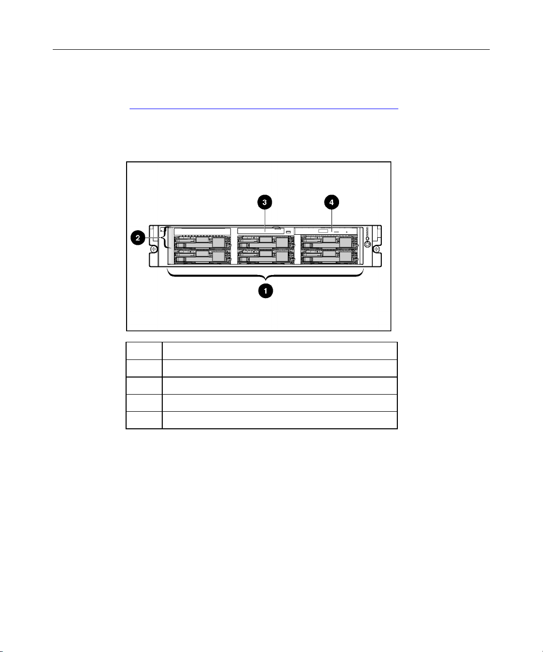
Front Panel Components
).
Item Description
1 Hard drive bays
2 Bay for tape drive or hard drive and tape drive blank
3 Diskette drive
4 CD-ROM drive
Page 11
Server Component Identification 11
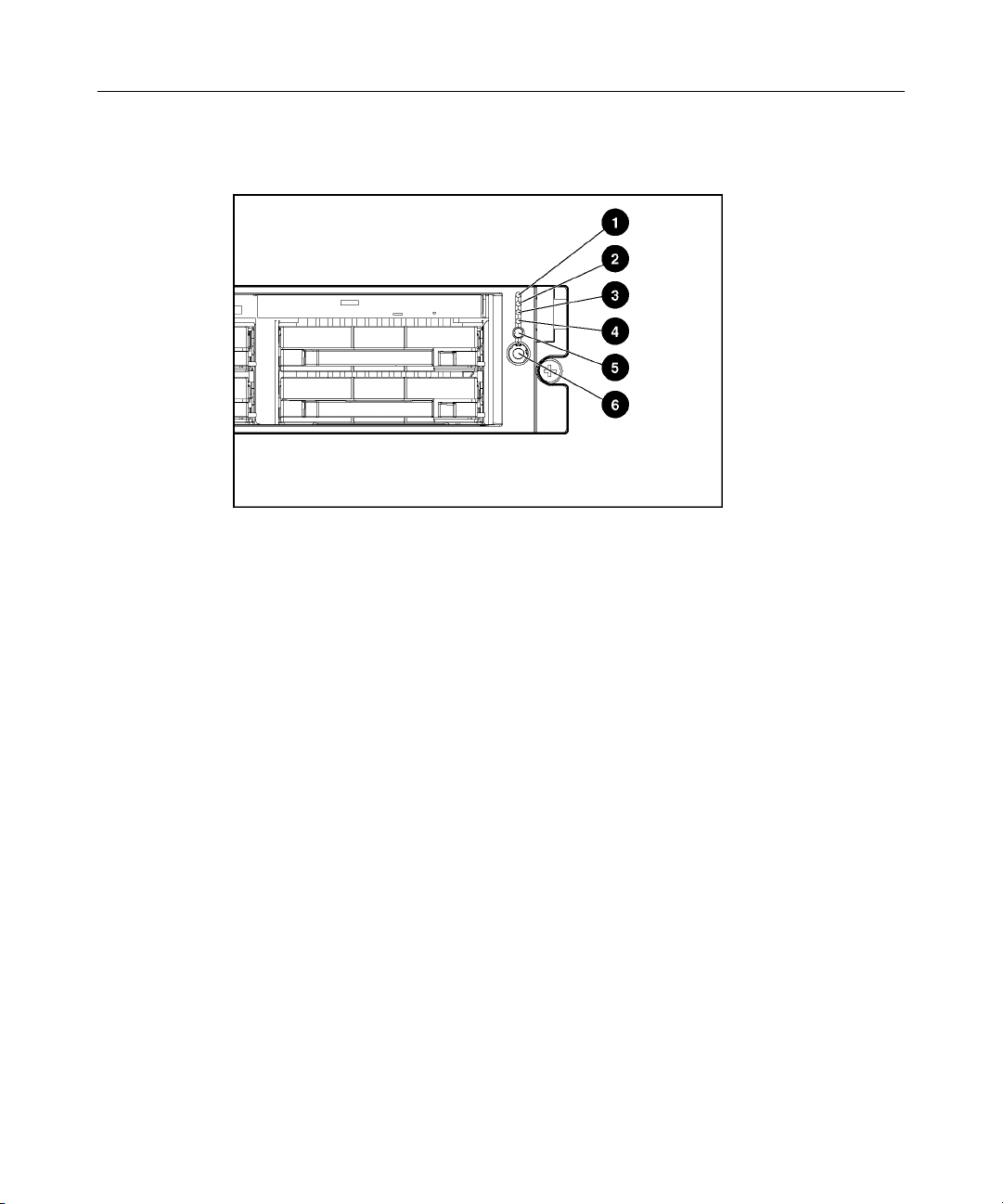
Front Panel LEDs and Buttons
Page 12

12 HP ProLiant DL380 Generation 3 Server User Guide
Item Description Status
1 Internal health LED Green = Normal
Amber = System degraded. Refer to system board LEDs to
identify component in degraded state.
Red = System critical. Refer to system board LEDs to identify
component in critical state.
2 External health LED
(power supply)
Green = Normal
Amber = Power redundancy failure
Red = Critical power supply failure
3 NIC 1 link/activity LED Green = Network link
Flashing = Network link and activity
Off = No link to network. If power is off, view the rear panel
RJ-45 LEDs for status.
4 NIC 2 link/activity LED Green = Network link
Flashing = Network link and activity
Off = No link to network. If power is off, view the rear panel
RJ-45 LEDs for status.
5 UID LED button Blue = Activated
Flashing = System remotely managed
6 Power On/Standby
button/system power LED
Off = Deactivated
Green = System on
Amber = System shut down, but power still applied
Off = Power cord not attached or power supply failure
Page 13
Server Component Identification 13
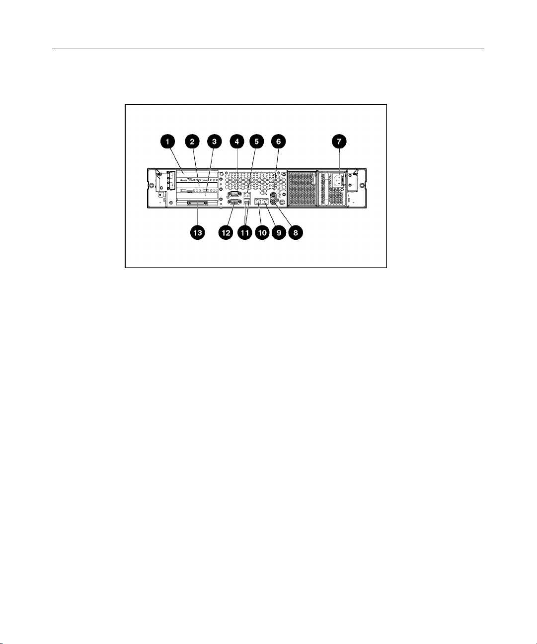
Rear Panel Components
Page 14

14 HP ProLiant DL380 Generation 3 Server User Guide
Item Description Connector Color
1 Hot-plug PCI-X expansion slot 3
(bus 6) 64-bit/100-MHz 3.3V
2 Hot-plug PCI-X expansion slot 2
(bus 6) 64-bit/100-MHz 3.3V
3 Non-hot-plug PCI-X expansion slot 1
(bus 3) 64-bit/133-MHz 3.3V
N/A
N/A
N/A
4 Serial connector Teal
5 iLO connector N/A
6 Mouse connector Green
7 Power cord connector N/A
8 Keyboard connector Purple
9 NIC 1 connector N/A
10 NIC 2 connector N/A
11 USB connectors Black
12 Video connector Blue
13 VHDCI SCSI connector (port 1) N/A
Page 15
Server Component Identification 15
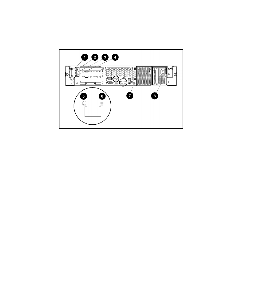
Rear Panel LEDs and Buttons
Page 16

16 HP ProLiant DL380 Generation 3 Server User Guide
Item Description LED Color Status
1 PCI Hot Plug fault LED
(slot 3)
2 PCI Hot Plug power LED
(slot 3)
3 PCI Hot Plug fault LED
(slot 2)
4 PCI Hot Plug power LED
(slot 2)
Amber On = Expansion board failed
Off = Normal
Green On = Power is applied to the slot
Flashing = Power is cycling
Off = Power is not applied to the slot
Amber On = Expansion board failed
Off = Normal
Green On = Power is applied to the slot
Flashing = Power is cycling
Off = Power is not applied to the slot
5 RJ-45 link LED Green On = Linked to network
Off = Not linked to network
6 RJ-45 activity LED Green On or flashing = Network activity
Off = No network activity
7 UID LED button Blue On = Activated
Flashing = System remotely managed
Off = Deactivated
8 Power supply LED Green On = Power turned on and power supply
functioning properly
Off = One or more of the following conditions
exists:
•
AC power unavailable
•
Power supply failed
•
Power supply in standby mode
•
Power supply exceeded current limit
Page 17
Server Component Identification 17
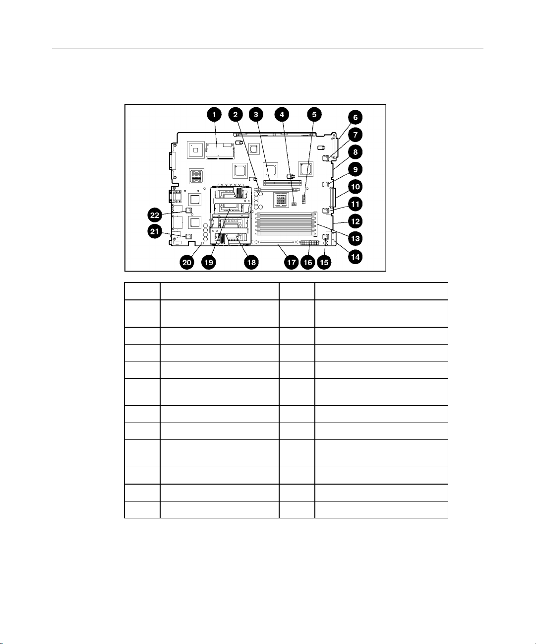
System Board Components
Item Description Item Description
1 Smart Array 5i Plus
Memory Module
2 PPM 2 slot 13 DIMM slots (1-6)
3 PCI riser cage connector 14 Power supply signal connector
4 Chassis ID switch 15 Fan 6 connector
5 System maintenance
switch
6 SCSI connector (port 2) 17 PPM 1 slot
7 Fan 3 connector 18 Processor 1 socket
8 CD-ROM drive system
connector
9 Fan 4 connector 20 NMI switch
10 SCSI connector (port 1) 21 Fan 2 connector
11 Fan 5 connector 22 Fan 1 connector
12 Diskette drive system
connector
16 System power connector
19 Processor 2 socket
Page 18

18 HP ProLiant DL380 Generation 3 Server User Guide
System Maintenance Switch
Position Default Function
S1 Off Off = iLO security is enabled.
On = iLO security is disabled.
S2 Off Off = System configuration can be
changed.
On = System configuration is
locked.
S3 Off Reserved
S4 Off Off = Booting from diskette is
controlled by RBSU.
On = Booting from diskette is
enabled and RBSU is overridden.
S5 Off Off = Power-on password is
enabled.
On = Power-on password is
disabled.
NMI Switch
S6 Off Off = No function
On = Clear NVRAM.*
* If you clear NVRAM, you must re-enter the server serial number
through RBSU ("Re-Entering the Server Serial Number" on page
118).
The NMI switch allows administrators to perform a memory dump before
performing a hard reset. Crash dump analysis is an essential part of eliminating
reliability problems, such as hangs or crashes in operating systems, device
drivers, and applications. Many crashes freeze a system, requiring you to do a
hard reset. Resetting the system erases any information that would support root
cause analysis.
Page 19
Server Component Identification 19
Systems running Microsoft Windows operating systems experience a blue screen
trap when the operating system crashes. When this happens, Microsoft
recommends that system administrators perform an NMI event by pressing a
dump switch. The NMI event enables a hung system to become responsive again.
Chassis ID Switch
The chassis ID switch on the system board is reserved for use by authorized
technicians only. Do not modify the switch setting.
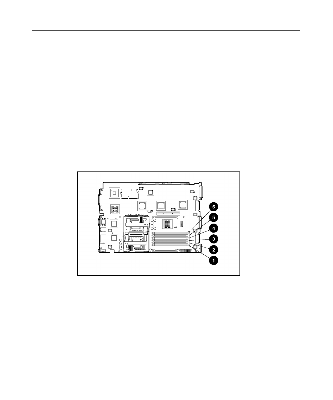
DIMM Slots
DIMM slots are numbered sequentially (1 through 6) and the paired banks are
identified by the letters A, B, and C.
Page 20
20 HP ProLiant DL380 Generation 3 Server User Guide
Item Description
1 DIMM slot 1A
2 DIMM slot 2A
3 DIMM slot 3B
4 DIMM slot 4B
5 DIMM slot 5C
6 DIMM slot 6C
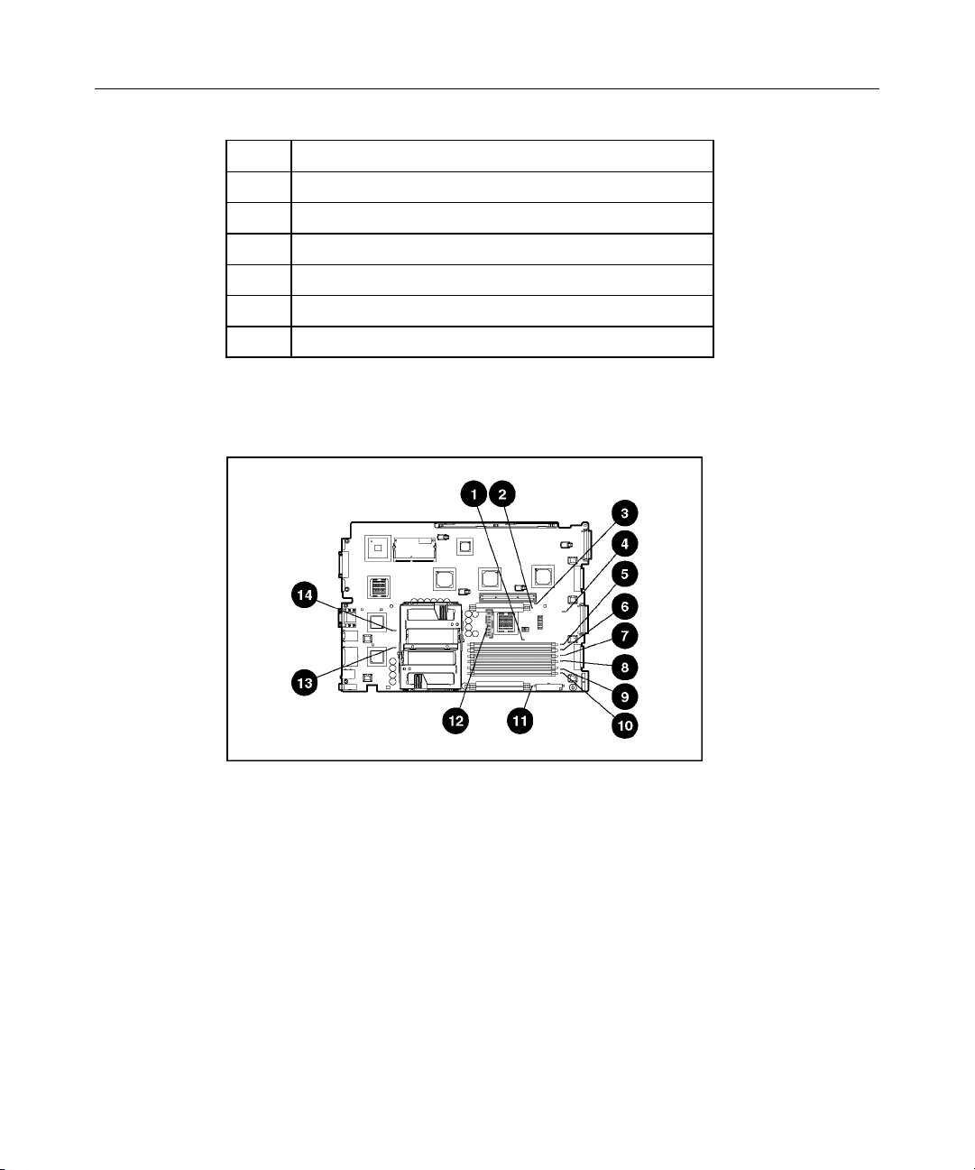
System Board LEDs
Page 21

Server Component Identification 21
Item LED Description Status
1 Online spare memory Amber = Failover, online spare memory in
use
Green = Enabled, but not in use
Off = Disabled
2 PPM 2 failure Amber = PPM failed
Off = Normal
3 Riser interlock Amber = PCI riser cage not seated
Off = PCI riser cage is seated
4 Overtemperature Amber = Cautionary or critical temperature
level detected
Off = Temperature OK
5 DIMM 6C failure Amber = Memory failed
Off = Normal
6 DIMM 5C failure Amber = Memory failed
Off = Normal
7 DIMM 4B failure Amber = Memory failed
Off = Normal
8 DIMM 3B failure Amber = Memory failed
Off = Normal
9 DIMM 2A failure Amber = Memory failed
Off = Normal
10 DIMM 1A failure Amber = Memory failed
Off = Normal
11 PPM 1 failure Amber = PPM failed
Off = Normal
12 iLO diagnostic LEDs Refer to the HP Integrated Lights-Out User
Guide on the Documentation CD.
13 Processor 1 failure Amber = Processor failed
Off = Normal
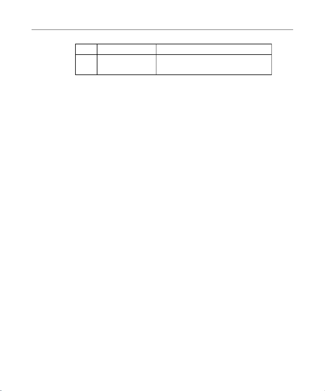
Page 22
22 HP ProLiant DL380 Generation 3 Server User Guide
Item LED Description Status
14 Processor 2 failure Amber = Processor failed
Off = Normal
System LEDs and Internal Health LED Combinations
When the internal health LED on the front panel illuminates either amber or red,
the server is experiencing a health event. Combinations of illuminated system
LEDs and the internal health LED indicate system status.
The front panel health LEDs indicate only the current hardware status. In some
situations, Insight Manager 7 may report server status differently than the health
LEDs because the software tracks more system attributes.
Page 23

Server Component Identification 23
System LED and
Color
Internal Health
LED Color
Status
Processor failure,
socket X (Amber)
Amber Processor in socket X is in a pre-failure condition.
Processor failure,
both sockets (Amber)
PPM failure, slot X
(Amber)
DIMM failure, slot X
(Amber)
Amber •
Red One or more of the following conditions may exist:
•
Processor in socket X has failed.
•
Processor in socket X failed over to the offline spare.
•
Processor X is not installed in the socket.
•
Processor X is unsupported.
•
ROM detects a failed processor during POST.
Red Processor types are mismatched.
Red • • PPM in slot X has failed.
PPM is not installed in slot X, but the corresponding
processor is installed.
Red • • DIMM in slot X has failed.
DIMM in slot X is an unsupported type, and no valid
memory exists in another bank.
DIMM in slot X has reached single-bit correctable
error threshold.
•
DIMM in slot X is in a pre-failure condition.
•
DIMM in slot X is an unsupported type, but valid
memory exists in another bank.
DIMM failure, all slots
in one bank (Amber)
Overtemperature
(Amber)
Riser interlock
(Amber)
Online spare memory
(Amber)
Power converter
module (Amber)
Red No valid or usable memory is installed in the system.
Red • • The Health Driver has detected a cautionary
temperature level.
The server has detected a hardware critical
temperature level.
Red PCI riser cage is not seated.
Amber Bank X failed over to the online spare memory bank.
Red Power converter module has failed.
Page 24
24 HP ProLiant DL380 Generation 3 Server User Guide
System LED and
Color
Fan (Amber) Amber Redundant fan has failed.
Red The minimum fan requirements are not being met. One
SCSI configuration
error (Amber)
Internal Health
LED Color
Red SCSI cabling or terminator configuration is incorrect for
Status
or more fans have failed or are missing.
SCSI backplane.
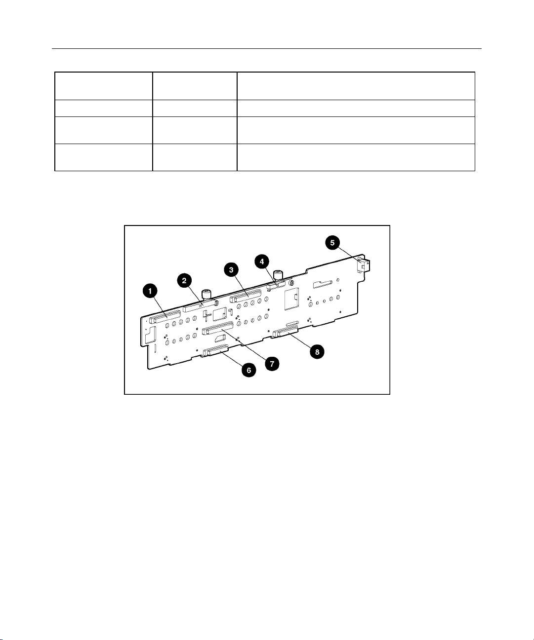
SCSI Backplane Components
Page 25
Server Component Identification 25
Item Description
1 SCSI connector (port 2)
2 CD-ROM drive connector
3 SCSI connector (port 1)
4 Diskette drive connector
5 Power connector
6 CD-ROM drive system connector
7 SCSI connector (used with a jumper or terminator
board)
8 Diskette drive system connector
SCSI Backplane LEDs
Page 26
26 HP ProLiant DL380 Generation 3 Server User Guide
Item LED Description Status
1 SCSI configuration On = Simplex
Off = Duplex
2 SCSI configuration error On = SCSI cabling or terminator
configuration is incorrect
Off = SCSI cabling or terminator
configuration is correct
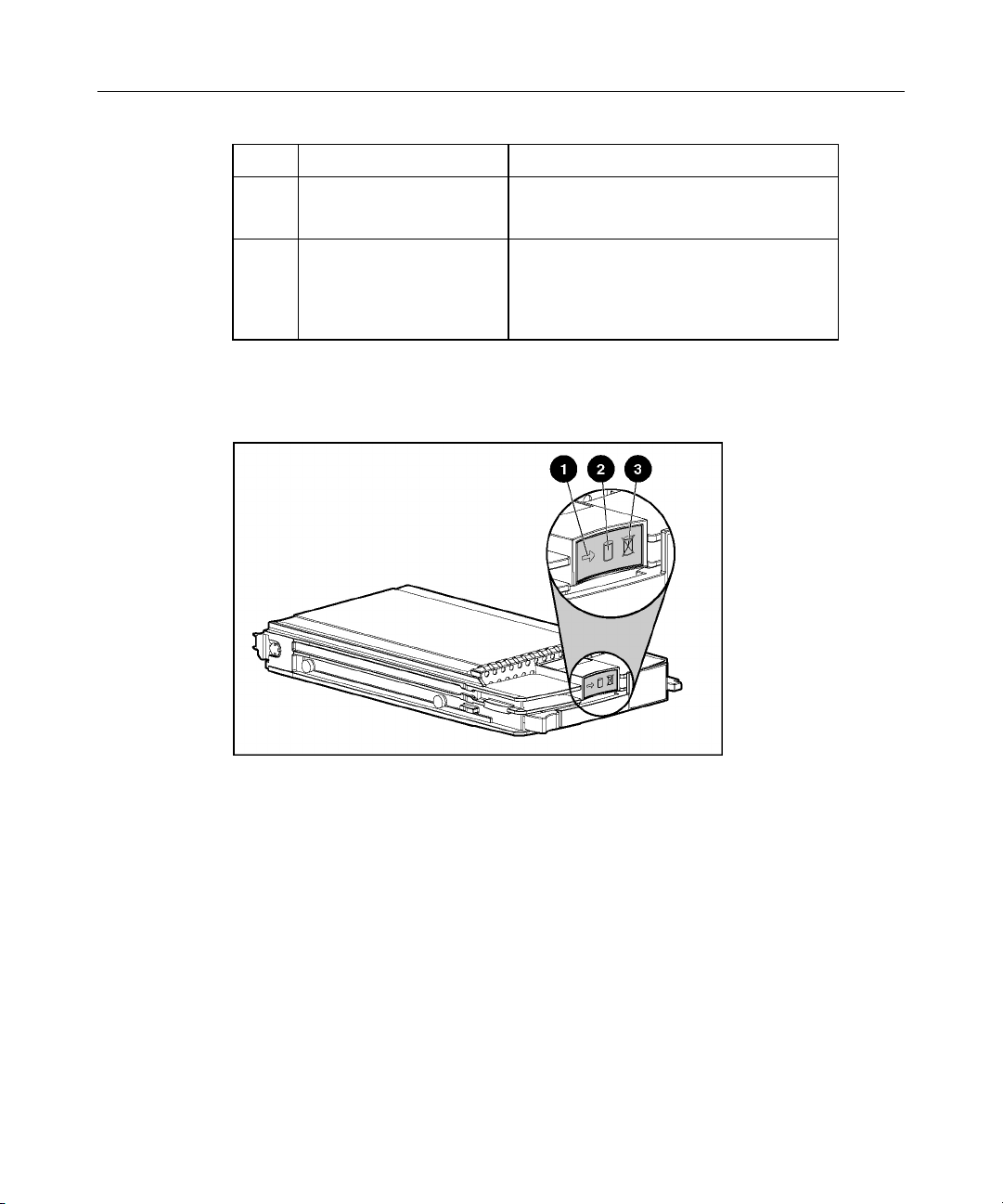
Hot-Plug SCSI Hard Drive LEDs
Page 27

Server Component Identification 27
Item LED Description Status
1 Activity status On = Drive activity
Flashing = High activity on the drive or
drive is being configured as part of an
array.
Off = No drive activity
2 Online status On = Drive is part of an array and is
currently working.
Flashing = Drive is actively online.
Off = Drive is offline.
3 Fault status On = Drive failure
Flashing = Fault-process activity
Off = No fault-process activity
Page 28

28 HP ProLiant DL380 Generation 3 Server User Guide
Hot-Plug SCSI Hard Drive LED Combinations
Activity
LED (1)
Online
LED (2)
Fault
LED (3)
Interpretation
On, off,
or
flashing
On, off,
or
flashing
On or
flashing
On Off Off
Flashing Flashing Flashing
Off Off On The drive has failed and been placed offline.
On or off Flashing A predictive failure alert has been received for this drive.
Replace the drive as soon as possible.
On Off The drive is online and is configured as part of an array.
If the array is configured for fault tolerance and all other drives in
the array are online, and a predictive failure alert is received or a
drive capacity upgrade is in progress, you may replace the drive
online.
Flashing Off
Do not remove the drive. Removing a drive may terminate the
current operation and cause data loss.
The drive is rebuilding or undergoing capacity expansion.
Do not remove the drive.
The drive is being accessed, but (1) it is not configured as part of
an array; (2) it is a replacement drive and rebuild has not yet
started; or (3) it is spinning up during the POST sequence.
Do not remove the drive. Removing a drive may cause data
loss in non-fault-tolerant configurations.
Either (1) the drive is part of an array being selected by an array
configuration utility; (2) Drive Identification has been selected in
Insight Manager; or (3) drive firmware is being updated.
You may replace the drive.
Off Off Off Either (1) the drive is not configured as part of an array; (2) the
drive is configured as part of an array, but it is a replacement drive
that is not being accessed or being rebuilt yet; or (3) the drive is
configured as an online spare.
If the drive is connected to an array controller, you may replace
the drive online.
Page 29
Server Component Identification 29
Internal PCI Hot Plug LEDs and Button
Item Description Status
1 Fault LED
(Amber)
2 Power LED
(Green)
3 PCI Hot Plug
button
On = Expansion board failed.
Off = Normal
On = Power is applied to the slot.
Flashing = Power is cycling.
Off = Power is not applied to the
slot.
N/A
Page 30

30 HP ProLiant DL380 Generation 3 Server User Guide
PCI Hot Plug LED Status Combinations
Power LED
(Green)
On Off No The power to the slot is on and the slot is functioning
On On No The power to the slot is on, but the slot needs attention for a
Flashing On or off No The power to the slot is being turned off or on, which may
Off On Yes The power to the slot is off, but the slot needs attention for a
Off Off Yes The power to the slot is off.
Fault LED
(Amber)
OK to
open?
Slot Status
normally. Do NOT open the slot release lever.
possible problem with the slot, board, or driver. DO NOT
open the slot release lever.
Examine the logs and Insight Manager 7. If the expansion
board is faulty, remove or replace the board.
take several seconds. DO NOT open the slot release lever.
To cancel the operation, press the PCI Hot Plug button.
possible problem with the slot, board, or driver.
Page 31

Server Component Identification 31
PCI Riser Cage LED
CAUTION: To prevent damage to the server or expansion
boards, power down the server and remove all AC power cords before
removing or installing the PCI riser cage.
Status
On = AC power connected
Off = AC power disconnected
Remote Management Connector
The 30-pin remote management connector, located on the PCI riser cage, is used
to cable the Remote Insight Lights-Out Edition II option. For more information,
refer to "RILOE II Cabling (on page 108)" or the Remote Insight Lights-Out
Edition II User Guide on the Documentation CD.
Page 32

32 HP ProLiant DL380 Generation 3 Server User Guide
Identifying Hot-Plug Fans
Page 33

Server Component Identification 33
Item Description Zone Configuration
1 Fan 1 Processor Redundant
2 Fan 2 Processor Primary
3 Fan 3 I/O Redundant
4 Fan 4 I/O and processor Primary (shared)
5 Fan 5 Processor Primary
6 Fan 6 Processor Primary
7 Fan 7 Power supply and
8 Fan 8 Power supply Redundant
Hot-Plug Fan LED
Status
Primary (shared)
processor
Green = Operating normally
Amber = Failed
Off = No power
Page 34

34 HP ProLiant DL380 Generation 3 Server User Guide
Power Converter Module LED
Status
Amber = Failed
Off = Operating normally
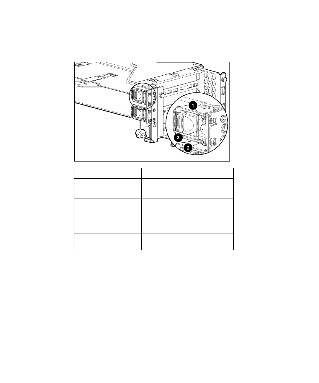
Battery-Backed Write Cache Enabler LEDs
Page 35

Server Component Identification 35
Item LED Color
1 Amber
2 Green
For LED status information, refer to "Battery-Backed Write Cache Enabler LED
Statuses (on page 35)."
Battery-Backed Write Cache Enabler LED Statuses
Server Status LED Status Battery Module Status
Server is on and has normal run
Green = On Fast charging
time
Green = Off Trickle charging
Amber = On A short exists in the connection of one or more
of the four button cells within the battery
module
Amber = Blinking An open exists in the circuit between the
positive and negative terminals of the battery
module
Amber = Off Normal
Server is on and is in the first 30
seconds after power up
Server is off and is in data
retention mode
Green = On
Amber = On
Amber = Blinking every
15 seconds
Temporary lock-out state; data was lost due to
cable being detached
User data held in write cache is being backed
up
Page 36

Page 37

37
Server Operations
In This Section
Powering Up the Server.......................................................................................................... 37
Powering Down the Server.....................................................................................................37
Extending the Server from the Rack....................................................................................... 38
Removing the Access Panel ...................................................................................................40
Installing the Access Panel .....................................................................................................40
Removing the PCI Riser Cage................................................................................................ 40
Installing the PCI Riser Cage .................................................................................................42
Powering Up the Server
To power up the server, press the Power On/Standby button.
Powering Down the Server
WARNING: To reduce the risk of personal injury, electric
shock, or damage to the equipment, remove the power cord to
remove power from the server. The front panel Power On/Standby
button does not completely shut off system power. Portions of the
power supply and some internal circuitry remain active until AC
power is removed.
IMPORTANT: If installing a hot-plug device, it is not necessary to
power down the server.
1. Back up the server data.
2. Shut down the operating system as directed by the operating system
documentation.
3. If the server is installed in a rack, press the UID LED button on the front
panel (1). Blue LEDs illuminate on the front and rear panels of the server.
Page 38

38 HP ProLiant DL380 Generation 3 Server User Guide
4. Press the Power On/Standby button to place the server in standby mode (2).
When the server activates standby power mode, the system power LED
changes to amber.
5. If the server is installed in a rack, locate the server by identifying the
illuminated rear UID LED button.
6. Disconnect the power cords.
The system is now without power.
Extending the Server from the Rack
1. Loosen the thumbscrews that secure the server faceplate to the front of the
rack.
2. Extend the server on the rack rails until the server rail-release latches engage.
Page 39

Server Operations 39
WARNING: To reduce the risk of personal injury or
equipment damage, be sure that the rack is adequately stabilized
before extending a component from the rack.
WARNING: To reduce the risk of personal injury, be
careful when pressing the server rail-release latches and sliding
the server into the rack. The sliding rails could pinch your fingers.
3. After performing the installation or maintenance procedure, slide the server
back into the rack:
a. Press the server rail-release latches and slide the server fully into rack.
b. Secure the server by tightening the thumbscrews.
Page 40

40 HP ProLiant DL380 Generation 3 Server User Guide
Removing the Access Panel
WARNING: To reduce the risk of personal injury from hot
surfaces, allow the drives and the internal system components to
cool before touching them.
CAUTION: Do not operate the server for long periods without
the access panel. Operating the server without the access panel results
in improper airflow and improper cooling that can lead to thermal
damage.
1. Power down the server if performing a non-hot-plug installation or
maintenance procedure ("Powering Down the Server" on page 37).
2. Extend the server from the rack, if applicable ("Extending the Server from
the Rack" on page 38).
3. Lift up on the hood latch handle and remove the access panel.
Installing the Access Panel
1. Place the access panel on top of the server with the hood latch open. Allow
the panel to extend past the rear of the server approximately 1.25 cm (0.5 in).
2. Push down on the hood latch. The access panel slides to a closed position.
Removing the PCI Riser Cage
CAUTION: To prevent damage to the server or expansion
boards, power down the server and remove all AC power cords before
removing or installing the PCI riser cage.
1. Power down the server ("Powering Down the Server" on page 37).
2. Extend the server from the rack, if applicable ("Extending the Server from
the Rack" on page 38).
3. Remove the access panel ("Removing the Access Panel" on page 40).
Page 41

Server Operations 41
4. Disconnect any internal or external cables connected to any existing
expansion boards.
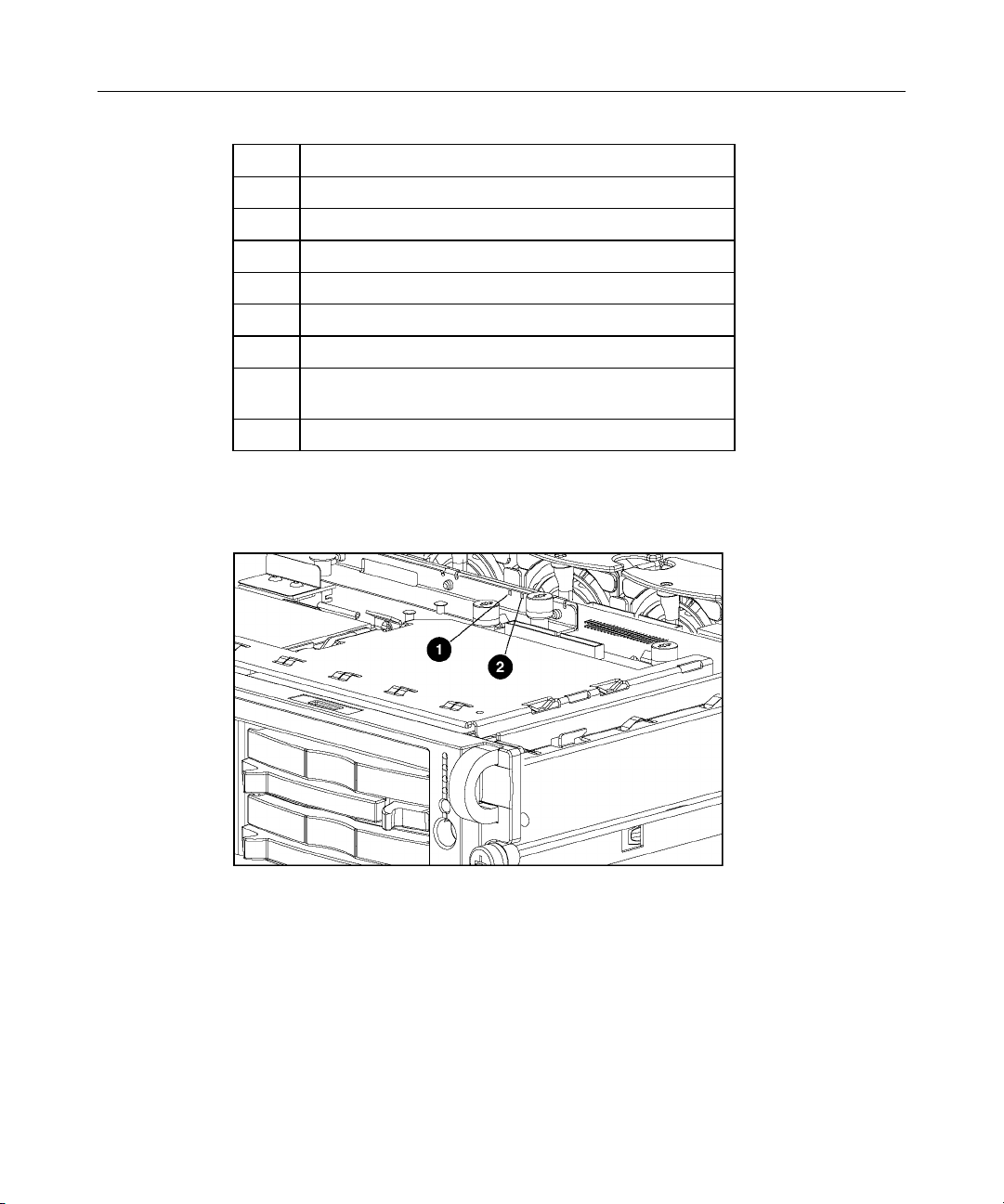
5. Lift the PCI riser cage thumbscrews (1) and turn them counter-clockwise (2).
6. Remove the PCI riser cage (3).
Page 42

42 HP ProLiant DL380 Generation 3 Server User Guide
Installing the PCI Riser Cage
CAUTION: To prevent damage to the server or expansion
boards, power down the server and remove all AC power cords before
removing or installing the PCI riser cage.
1. Align the PCI riser cage with the chassis and slide it into place.
2. Tighten the thumbscrews to secure the PCI riser cage:
a. Lift the thumbscrew knobs (1).
b. Turn the thumbscrews clockwise while pressing down, until tightened
(2).
Page 43

Server Operations 43
c. Turn the thumbscrews counterclockwise to lower thumbscrew knobs (3).
Page 44

Page 45

45
Server Setup
In This Section
Optional Installation Services................................................................................................. 45
Rack Planning Resources .......................................................................................................46
Optimum Environment ........................................................................................................... 47
Rack Warnings .......................................................................................................................50
Identifying the Contents of the Server Shipping Carton.........................................................51
Installing Hardware Options................................................................................................... 52
Installing the Server into the Rack .........................................................................................52
Powering Up and Configuring the Server ..............................................................................62
Installing the Operating System .............................................................................................63
Registering the Server ............................................................................................................63
Optional Installation Services
You may choose to have HP install the system. The installation service can be
purchased as a Care Pack packaged service or as a customized service agreement
to meet your specific requirements. Some of the Care Pack services are as
follows:
•
Hardware installation services
•
Hardware and operating system installation for ProLiant servers
•
Installation and start-up services for some operating systems
•
Installation and start-up services for Insight Manager
This optional hardware installation service is available in all countries where HP
has a direct or indirect service presence. The service may be ordered from and
provided by an authorized service reseller or, in the United States only, the
service may be ordered by calling 1-800-652-6672. In the United States, HP
makes all the arrangements to have the system installed by qualified guaranteed
service providers. For more information, refer to the HP website
(http://www.hp.com/hps
).
Page 46

46 HP ProLiant DL380 Generation 3 Server User Guide
For a list of operating systems, supported by the server, refer to the HP website
(ftp://ftp.compaq.com/pub/products/servers/os-support-matrix-310.pdf
Rack Planning Resources
The rack resource kit ships with all HP branded or Compaq branded 9000,
10000, and H9 series racks. A summary of the content of each resource follows:
• The Rack Builder Pro Configuration Tool enables you to simulate potential
rack configurations based on your input and provides the following
information:
− Graphical preview of properly configured racks
− Site planning data, including power requirements, cooling mandates, and
physical specifications
− Ordering information, including required components, part numbers, and
appropriate quantities
For more information, refer to the HP website
(http://www.hp.com/products/servers/platforms
).
).
• • The Installing Rack Products video provides a visual overview of operations
required for configuring a rack with rack-mountable components. It also
provides the following important configuration steps:
− Planning the site
− Installing rack servers and rack options
− Cabling servers in a rack
− Coupling multiple racks
The Rack Products Documentation CD enables you to view, search, and print
documentation for HP and Compaq branded racks and rack options. It also
helps you set up and optimize a rack in a manner that best fits your
environment.
If you intend to deploy and configure multiple servers in a single rack, refer to
the white paper on high-density deployment on the HP website
(http://www.hp.com/products/servers/platforms
).
Page 47

Server Setup 47
Optimum Environment
When installing the server in a rack, select a location that meets the
environmental standards described in this section.
Space and Airflow Requirements
To allow for servicing and adequate airflow, observe the following space and
airflow requirements when deciding where to install a rack:
•
Leave a minimum clearance of 63.5 cm (25 in) in front of the rack.
•
Leave a minimum clearance of 76.2 cm (30 in) behind the rack.
•
Leave a minimum clearance of 121.9 cm (48 in) from the back of the rack to
the back of another rack or row of racks.
HP servers draw in cool air through the front door and expel warm air through
the rear door. Therefore, the front and rear rack doors must be adequately
ventilated to allow ambient room air to enter the cabinet, and the rear door must
be adequately ventilated to allow the warm air to escape from the cabinet.
CAUTION: To prevent improper cooling and damage to the
equipment, do not block the ventilation openings.
When there is vertical space in the rack not filled by a server or rack component,
the gaps between the components cause changes in airflow through the rack and
across the servers. Cover all gaps with blanking panels to maintain proper
airflow.
CAUTION: Always use blanking panels to fill empty vertical
spaces in the rack. This arrangement ensures proper airflow. Using a
rack without blanking panels results in improper cooling that can lead to
thermal damage.
The 9000 and 10000 Series racks provide proper server cooling from flowthrough perforations in the front and rear doors that provide 64 percent open area
for ventilation.
Page 48

48 HP ProLiant DL380 Generation 3 Server User Guide
CAUTION: When using a Compaq branded 7000 Series rack,
you must install the high airflow rack door insert [P/N 327281-B21 (42U)
or P/N 157847-B21 (22U)] to provide proper front-to-back airflow and
cooling.
CAUTION: If a third-party rack is used, observe the following
additional requirements to ensure adequate airflow and to prevent
damage to the equipment:
• • Front and rear doors—If the 42U server rack includes closing front
and rear doors, you must allow 5,350 sq cm (830 square inches) of
holes evenly distributed from top to bottom to permit adequate
airflow (equivalent to the required 64 percent open area for
ventilation).
Side—The clearance between the installed rack component and the
side panels of the rack must be a minimum of 7 cm (2.75 inches).
Temperature Requirements
To ensure continued safe and reliable equipment operation, install or position the
system in a well-ventilated, climate-controlled environment.
The maximum recommended ambient operating temperature (TMRA) for most
server products is 35°C (95°F). The temperature in the room where the rack is
located must not exceed 35°C (95°F).
CAUTION: To reduce the risk of damage to the equipment
when installing third-party options:
• • Do not permit optional equipment to impede airflow around the
server or to increase the internal rack temperature beyond the
maximum allowable limits.
Do not exceed the manufacturer’s TMRA.
Page 49

Server Setup 49
Power Requirements
Installation of this equipment must comply with local and regional electrical
regulations governing the installation of information technology equipment by
licensed electricians. This equipment is designed to operate in installations
covered by NFPA 70, 1999 Edition (National Electric Code) and NFPA-75, 1992
(code for Protection of Electronic Computer/Data Processing Equipment). For
electrical power ratings on options, refer to the product rating label or the user
documentation supplied with that option.
WARNING: To reduce the risk of personal injury, fire, or
damage to the equipment, do not overload the AC supply branch
circuit that provides power to the rack. Consult the electrical
authority having jurisdiction over your facility’s wiring and
installation requirements.
CAUTION: Protect the server from power fluctuations and
temporary interruptions with a regulating uninterruptible power supply
(UPS). This device protects the hardware from damage caused by
power surges and voltage spikes and keeps the system in operation
during a power failure.
When installing more than one server, you may need to use additional power
distribution devices to safely provide power to all devices. Observe the following
guidelines:
•
Balance the server power load between available AC supply branch circuits.
•
Do not allow the overall system AC current load to exceed 80 percent of the
branch circuit AC current rating.
•
Do not use common power outlet strips for this equipment.
•
Provide a separate electrical circuit for the server.
Page 50

50 HP ProLiant DL380 Generation 3 Server User Guide
Electrical Grounding Requirements
The server must be grounded properly for proper operation and safety. In the
United States, you must install the equipment in accordance with NFPA 70, 1999
Edition (National Electric Code), Article 250, as well as any local and regional
building codes. In Canada, you must install the equipment in accordance with
Canadian Standards Association, CSA C22.1, Canadian Electrical Code. In all
other countries, you must install the equipment in accordance with any regional
or national electrical wiring codes, such as the International Electrotechnical
Commission (IEC) Code 364, parts 1 through 7. Furthermore, you must be sure
that all power distribution devices used in the installation, such as branch wiring
and receptacles, are listed or certified grounding-type devices.
Because of the high ground-leakage currents associated with multiple servers
connected to the same power source, HP recommends the use of a power
distribution unit (PDU) that is either permanently wired to the building’s branch
circuit or includes a nondetachable cord that is wired to an industrial-style plug.
NEMA locking-style plugs or those complying with IEC 60309 are considered
suitable for this purpose. Using common power outlet strips for the server is not
recommended.
Rack Warnings
damage to the equipment, be sure that:
•
•
•
•
WARNING: To reduce the risk of personal injury or
The leveling jacks are extended to the floor. •
The full weight of the rack rests on the leveling jacks.
The stabilizing feet are attached to the rack if it is a single-rack
installation.
The racks are coupled together in multiple-rack installations.
Only one component is extended at a time. A rack may become
unstable if more than one component is extended for any
reason.
Page 51

Server Setup 51
WARNING: To reduce the risk of personal injury or
equipment damage when unloading a rack:
At least two people are needed to safely unload the rack from
•
the pallet. An empty 42U rack can weigh as much as 115 kg
(253 lb), can stand more than 2.1 m (7 ft) tall, and may become
unstable when being moved on its casters.
•
Never stand in front of the rack when it is rolling down the ramp
from the pallet. Always handle the rack from both sides.
Identifying the Contents of the Server Shipping Carton
Unpack the server shipping carton and locate the materials and documentation
necessary for installing the server. All the rack-mounting hardware necessary for
installing the server into the rack is included with the rack or the server.
The contents of the server shipping carton include:
•
Server
•
Printed setup documentation, Documentation CD, and software products
•
Power cord
•
Rack-mounting hardware
In addition to these supplied items, you may need:
•
Application software diskettes
Page 52

52 HP ProLiant DL380 Generation 3 Server User Guide
• Options to be installed
Item Description
1 Server rails
2 Left and right standard rack rail assemblies
3 Cable management arm
4 Rack template
Installing Hardware Options
Install any hardware options before initializing the server. For options installation
information, refer to the option documentation. For server-specific information,
refer to "Hardware Options Installation (on page 65)."
Installing the Server into the Rack
Follow the steps in this section if you are installing the server into a rack with
square holes. If you are installing the server into a rack with round holes, order
the appropriate rack installation option kit, and then refer to the installation
instructions that ship with the option kit for more information.
Page 53

Server Setup 53
NOTE: The steps in this section work with most third-party racks with
square holes. If they do not work with the rack you are using, order the
option kit for racks with round holes.
If you are installing the server into a telco rack, order the appropriate option kit at
the RackSolutions.com website (http://www.racksolutions.com/hp
). Follow the
server-specific instructions on the website to install the rack brackets. After
installing the brackets, follow the steps in this section.
WARNING: When installing a server in a telco rack, be
sure that the rack frame is adequately secured to the top and
bottom of the building structure.
1. Mark the rack.
CAUTION: Always plan the rack installation so that the
heaviest item is on the bottom of the rack. Install the heaviest item first,
and continue to populate the rack from the bottom to the top.
Page 54

54 HP ProLiant DL380 Generation 3 Server User Guide
NOTE: Rack components are removed for clarity.
2. Secure each server rail to the server.
3. Secure the left and right standard rack rails to the appropriate side of the
rack.
4. Extend the slides from the standard rack rails, and then slide the server rails
into the slides.
Page 55

Server Setup 55
WARNING: To reduce the risk of personal injury or
equipment damage, be sure that the rack is adequately stabilized
before sliding the server rails into the rack rails.
CAUTION: Be sure to keep the server parallel to the floor
when sliding the server rails into the rack rails. Tilting the server up or
down could result in damage to the rails.
5. Press the rail-release latches and slide the server into the rack.
Page 56

56 HP ProLiant DL380 Generation 3 Server User Guide
WARNING: To reduce the risk of personal injury, be
careful when pressing the server rail-release latches and sliding
the server into the rack. The sliding rails could pinch your fingers.
6. Secure the server to the rack.
Page 57

Server Setup 57
7. Secure the cable management arm bracket to the server.
NOTE: Cable management arm is removed for clarity.
8. Secure the cable management bracket to the rail.
9. Connect peripheral devices to the server.
Page 58

58 HP ProLiant DL380 Generation 3 Server User Guide
WARNING: To reduce the risk of electric shock, fire, or
damage to the equipment, do not plug telephone or
telecommunications connectors into RJ-45 connectors.
IMPORTANT: If the RILOE II board is installed in the server, be sure
that you attach the video cable to the video connector on the rear of the
RILOE II board. The standard video connector on the server rear panel
is not used when the RILOE II board is installed. For more information,
refer to the HP Remote Insight Lights-Out Edition II User Guide on the
Documentation CD.
Page 59

Server Setup 59
Item Description Connector Color
1 Hot-plug PCI-X expansion slot 3
(bus 6) 64-bit/100-MHz 3.3V
2 Hot-plug PCI-X expansion slot 2
(bus 6) 64-bit/100-MHz 3.3V
3 Non-hot-plug PCI-X expansion slot 1
(bus 3) 64-bit/133-MHz 3.3V
4 Serial connector Teal
5 iLO connector N/A
6 Mouse connector Green
7 Power cord connector N/A
8 Keyboard connector Purple
9 NIC 1 connector N/A
10 NIC 2 connector N/A
11 USB connectors Black
12 Video connector Blue
13 VHDCI SCSI connector (port 1) N/A
N/A
N/A
N/A
10. Connect the power cord to the back of the server.
11. If you chose not to install the cable management arm, install the power cord
anchor.
Page 60

60 HP ProLiant DL380 Generation 3 Server User Guide
a. Secure the power cord anchor to the server, and then insert the tie wrap
into the groove on the power cord anchor.
NOTE: Peripheral device cables are removed for clarity.
b. Place the power cord across the tie wrap at the following locations:
21.59 cm (8.5 inches) from the end of the redundant power supply cord
27.94 cm (11 inches) from the end of the primary power supply cord
Page 61

Server Setup 61
NOTE: If using the power cord anchor, be sure to leave enough slack
in the power cord so that the redundant power supply can be removed
without disconnecting the power cord from the primary power supply.
c. Secure the tie wrap around the power cord to prevent accidental
disengagement.
12. Secure cables to the cable management arm.
13. Connect the power cord to the AC power source.
Page 62

62 HP ProLiant DL380 Generation 3 Server User Guide
WARNING: To reduce the risk of electric shock or damage
to the equipment:
Do not disable the power cord grounding plug. The grounding
•
plug is an important safety feature.
•
Plug the power cord into a grounded (earthed) electric outlet
that is easily accessible at all times.
•
Unplug the power cord from the power supply to disconnect
power to the equipment.
•
Do not route the power cord where it can be walked on or
pinched by items placed against it. Pay particular attention to
the plug, electric outlet, and the point where the cord extends
from the server.
Powering Up and Configuring the Server
To power up the server, press the Power On/Standby button.
While the server boots, RBSU and the ORCA utility are automatically
configured to prepare the server for operating system installation. To configure
these utilities manually:
•
Press the F8 key when prompted during the array controller initialization to
configure the array controller using ORCA. The array controller defaults to
RAID 0 with one drive installed and RAID 1 with more than one drive
installed.
•
Press the F9 key when prompted during the boot process to change the server
settings, such as the settings for language and operating system, using RBSU.
The system is set up by default for the English language and a Microsoft
Windows 2000 installation.
For more information on the automatic configuration, refer to the HP ROM-
Based Setup Utility User Guide located on the Documentation CD.
Page 63

Server Setup 63
Installing the Operating System
To operate properly, the server must have a supported operating system. For the
latest information on supported operating systems, refer to the HP website
(ftp://ftp.compaq.com/pub/products/servers/os-support-matrix-310.pdf
Two methods are available to install an operating system on the server:
• • SmartStart assisted installation—Insert the SmartStart CD into the CD-ROM
drive and reboot the server.
Manual installation—Insert the operating system CD into the CD-ROM drive
and reboot the server. This process may require you to obtain additional
drivers from the HP website (http://www.hp.com/support
).
Follow the on-screen instructions to begin the installation process.
For information on using these installation paths, refer to the SmartStart
installation poster in the ProLiant Essentials Foundation Pack, included with the
server.
).
Registering the Server
Register the server at the HP website (http://register.hp.com).
Page 64

Page 65

65
Hardware Options Installation
In This Section
Introduction ............................................................................................................................65
Processor Option ....................................................................................................................65
Memory Options..................................................................................................................... 69
Hot-Plug SCSI Hard Drive Options .......................................................................................72
Hot-Plug Tape Drive Option ..................................................................................................75
Battery-Backed Write Cache Enabler Option.........................................................................77
Redundant Hot-Plug Fans....................................................................................................... 79
Redundant Hot-Plug AC Power Supply Option .....................................................................84
DC Power Supply Option....................................................................................................... 87
Expansion Board Options....................................................................................................... 91
Introduction
If more than one option is being installed, read the installation instructions for all
of the hardware options and identify similar steps to streamline the installation
process.
WARNING: To reduce the risk of personal injury from hot
surfaces, allow the drives and the internal system components to
cool before touching them.
properly ground the server before beginning any installation procedure.
Improper grounding can cause electrostatic discharge.
Processor Option
The server supports single- and dual-processor operation. With two processors
installed, the server supports boot functions through the processor installed in
processor socket 1. However, if processor 1 fails, the system automatically boots
from processor 2 and provides a processor failure message.
CAUTION: To prevent damage to electric components,
Page 66

66 HP ProLiant DL380 Generation 3 Server User Guide
The server uses PPMs as DC-to-DC converters to provide the proper power to
each processor. Each PPM must be installed in the slot adjacent to its processor.
CAUTION: To prevent thermal instability and damage to the
server, do not separate the processor from the heatsink. The processor,
heatsink, and retaining clip make up a single assembly.
CAUTION: To prevent possible server malfunction and
damage to the equipment, do not mix processors of different types.
IMPORTANT: If upgrading processor speed, update the system ROM
before installing the processor.
IMPORTANT: Processor socket 1 and PPM slot 1 must be populated
at all times or the server will not function properly.
IMPORTANT: Always install a PPM when you install a processor. The
system fails to boot if the PPM is missing.
To install a processor:
1. Power down the server ("Powering Down the Server" on page 37).
2. Extend the server from the rack, if applicable ("Extending the Server from
the Rack" on page 38).
3. Remove the access panel ("Removing the Access Panel" on page 40).
4. Open the processor retaining bracket.
Page 67

Hardware Options Installation 67
5. Release the processor locking lever.
CAUTION: Failure to open the processor locking lever
completely prevents the processor from seating during installation,
leading to hardware damage.
6. Install the processor.
Page 68

68 HP ProLiant DL380 Generation 3 Server User Guide
CAUTION: To prevent possible server malfunction or damage
to the equipment, be sure to completely close the processor locking
lever.
IMPORTANT: Processor 2 is oriented 180 degrees from processor 1.
7. Close the processor retaining bracket.
8. Open the latches on the corresponding PPM slot.
Page 69

Hardware Options Installation 69
9. Install the PPM.
NOTE: The appearance of compatible PPMs may vary.
10. Install the access panel ("Installing the Access Panel" on page 40).
Memory Options
You can expand server memory by installing PC2100 Registered DDR SDRAM
DIMMs. The system supports up to six DIMMs.
NOTE: The Advanced Memory Protection option in RBSU provides
additional memory protection beyond Advanced ECC. By default, the
server is set to Advanced ECC Support. Refer to "ROM-Based Setup
Utility (on page 111)," on the Documentation CD, for more information.
The server supports two types of memory configurations:
• • Standard memory configuration for maximum performance
− 2.4-GHz and 2.8-GHz models—up to 6 GB active memory (six 1-GB
memory modules)
− 3.06-GHz or greater models—up to 12 GB of active memory (six 2-GB
memory modules)
Online spare memory configuration for maximum availability
Page 70

70 HP ProLiant DL380 Generation 3 Server User Guide
− 2.4-GHz and 2.8 GHz models— up to 4 GB active memory and 2 GB
online spare memory
− 3.06-GHz or greater models—up to 8 GB of active memory and 4 GB of
online spare memory
Refer to "DIMM Slots (on page 19)" for DIMM slot locations and bank
assignments.
Online Spare Memory Configuration
In the online spare configuration, the ROM automatically configures the last
populated bank as the spare memory. If only banks A and B are populated,
bank B is the spare bank. If banks A, B, and C are populated, bank C is the spare
bank. If DIMMs in a non-spare bank exceed the limit for the single-bit
correctable errors threshold as defined by the Pre-Failure Warranty, the system
copies the memory contents of the failing bank to the spare bank. The system
then deactivates the failing bank and automatically switches over to the spare
bank.
For online spare memory support, you must observe the following guidelines:
•
The ROM must be up to date.
•
DIMMs installed in a spare bank must be of equal or greater capacity than
the DIMMs installed in other banks.
For example, if bank A is populated with two 256-MB DIMMs and bank B is
populated with two 512-MB DIMMs, bank C must be populated with two
512-MB or greater DIMMs in order for online spare memory support to
function properly.
After installing DIMMs, use RBSU to configure the system for online spare
memory support ("Configuring Online Spare Memory" on page 118).
DIMM Installation Guidelines
You must observe the following guidelines when installing additional memory:
•
Always install memory in pairs of two identical DIMMs.
Page 71

Hardware Options Installation 71
•
Install only PC2100 Registered DDR SDRAM DIMMs, 2.5 volts, 72 bits
wide, and ECC.
•
Install DIMMs with the same speed.
•
Install DIMMs into both slots within a single bank. Install DIMMs in order.
•
Upgrade memory by installing DIMM pairs into banks in sequential bank
order, starting with bank B.
For online spare memory support, you must also observe additional guidelines
("Online Spare Memory Configuration" on page 70).
Installing DIMMs
1. Power down the server ("Powering Down the Server" on page 37).
2. Extend the server from the rack, if applicable ("Extending the Server from
the Rack" on page 38).
3. Remove the access panel ("Removing the Access Panel" on page 40).
4. Open the DIMM slot latches.
5. Install the DIMM.
6. Install the access panel ("Installing the Access Panel" on page 40).
Page 72

72 HP ProLiant DL380 Generation 3 Server User Guide
7. If you are installing DIMMs in an online spare configuration, use RBSU to
configure this feature ("Configuring Online Spare Memory" on page 118).
Hot-Plug SCSI Hard Drive Options
When adding SCSI hard drives to the server, observe the following general
guidelines:
•
A maximum of 14 SCSI devices per channel can be added.
•
Each SCSI drive must have a unique ID. The system automatically sets all
SCSI IDs.
•
The SCSI ID for each hot-plug hard drive is set automatically to the next
sequential ID number in a series beginning with ID0.
•
If only one SCSI hard drive is used, install it in the bay with the lowest
number.
•
Hot-plug hard drives must be either Wide Ultra2 or Ultra3 SCSI types.
Mixing these types with other drive standards degrades the overall
performance of the drive subsystem.
SCSI IDs
•
Drives must be the same capacity to provide the greatest storage space
efficiency when drives are grouped together into the same drive array.
The server supports single- or dual-channel hard drive configurations. The
single-channel configuration (simplex) supports up to six hard drives on one
channel. The dual-channel configuration (duplex) supports two hard drives on
one channel (SCSI IDs 0 and 1) and up to four hard drives on the other channel
(SCSI IDs 2 through 5).
Page 73

Hardware Options Installation 73
The SCSI IDs for both simplex and duplex configurations are illustrated. Always
populate hard drive bays starting with the lowest SCSI ID.
Removing a Hard Drive Blank
CAUTION: To prevent improper cooling and thermal damage,
do not operate the server unless all bays are populated with either a
component or a blank.
Page 74

74 HP ProLiant DL380 Generation 3 Server User Guide
Removing a Hot-Plug SCSI Hard Drive
CAUTION: To prevent improper cooling and thermal damage,
do not operate the server unless all bays are populated with either a
component or a blank.
1. Determine the status of the hard drive from the hot-plug hard drive LEDs
("Hot-Plug SCSI Hard Drive LEDs" on page 26).
2. Back up all server data on the hard drive.
3. Remove the hard drive.
Installing a Hot-Plug SCSI Hard Drive
1. Remove the existing hard drive blank or hard drive from the drive bay
("Removing a Hard Drive Blank" on page 73, "Removing a Hot-Plug SCSI
Hard Drive" on page 74).
Page 75

Hardware Options Installation 75
2. Install the hard drive.
3. Determine the status of the hard drive from the hot-plug hard drive LEDs
("Hot-Plug SCSI Hard Drive LEDs" on page 26).
4. Resume normal server operations.
Hot-Plug Tape Drive Option
1. Remove the existing hard drive blank or hard drive from the upper-left drive
bay ("Removing a Hard Drive Blank" on page 73, "Removing a Hot-Plug
SCSI Hard Drive" on page 74).
Page 76

76 HP ProLiant DL380 Generation 3 Server User Guide
2. Remove the tape drive blank.
3. Install the tape drive.
Page 77

Hardware Options Installation 77
Battery-Backed Write Cache Enabler Option
The Battery-Backed Write Cache Enabler, also known as the battery module,
provides transportable data protection, increases overall controller performance,
and maintains any cached data for up to 72 hours. The NiMH batteries in the
battery module are continuously recharged through a trickle-charging process
whenever the system power is on. Under normal operating conditions, the battery
module lasts for 3 years before replacement is necessary.
For information on battery module LEDs, refer to "Battery-Backed Write Cache
Enabler LEDs (on page 34)" on the Documentation CD.
CAUTION: To prevent damage to the equipment or server
malfunction, do not add or remove the battery module while an array
capacity expansion, RAID level migration, or stripe size migration is in
progress.
CAUTION: After the server is powered down, wait 15 seconds
and then check the amber LED before unplugging the cable from the
battery module. If the amber LED blinks after 15 seconds, do not
remove the cable from the battery module. The battery module is
backing up data, and data will be lost if the cable is detached.
IMPORTANT: The battery module may have a low charge when
installed. In this case, a POST error message is displayed when the
server is powered up, indicating that the battery module is temporarily
disabled. No action is necessary on your part. The internal circuitry
automatically recharges the batteries and enables the battery module.
This process may take up to 4 hours. During this time, the array
controller will function properly but without the performance advantage
of the battery module.
NOTE: The data protection and the time limit also applies if a power
outage occurs. When power is restored to the system, an initialization
process writes the preserved data to the hard drives.
To install the Battery-Backed Write Cache Enabler:
1. Power down the server ("Powering Down the Server" on page 37).
2. Extend the server from the rack, if applicable ("Extending the Server from
the Rack" on page 38).
Page 78

78 HP ProLiant DL380 Generation 3 Server User Guide
3. Remove the access panel ("Removing the Access Panel" on page 40).
4. Remove the battery module bracket from the server.
5. Install the battery module into the bracket.
Page 79

Hardware Options Installation 79
6. Connect the cable and install the battery module assembly into the server.
7. Install the access panel ("Installing the Access Panel" on page 40).
8. Power up the server ("Powering Up the Server" on page 37).
Refer to the option documentation for more information.
Redundant Hot-Plug Fans
The server supports redundant hot-plug fans to provide proper airflow to the
system if a primary fan fails. The server airflow is divided into three zones:
processor, I/O, and power supply. Shared fans 4 and 7 each provide airflow for
two zones. If a shared fan fails, the failure is experienced in both zones.
In the standard configuration, five fans cool the server: fans 2, 4, 5, 6, and 7 in
the processor zone; fan 4 in the I/O zone; and fan 7 in the power supply zone.
For the redundant configuration, fans 1, 3, and 8 (one fan per zone) are added to
cool the server. This allows the server to continue operation in non-redundant
mode if only one fan fails per zone.
The server shuts down in the following scenarios:
• At POST:
Page 80

80 HP ProLiant DL380 Generation 3 Server User Guide
− The BIOS suspends the server for 5 minutes if it detects a cautionary
temperature level. If the cautionary temperature level is still detected
after 5 minutes, the BIOS performs an orderly shutdown and then
restarts. This process repeats until the cautionary temperature level is no
longer detected.
− The BIOS performs an orderly shutdown if the following minimum
requirements are not met: one working fan in the I/O zone, five working
fans in the processor zone, and one working fan in the power supply
zone.
− The server performs an immediate shutdown if it detects a critical
temperature level.
IMPORTANT: An immediate shutdown is a hardware-controlled
function and it overrides any firmware or software actions.
• In the operating system:
− With the Health Driver loaded and Thermal Shutdown enabled in RBSU,
the Health Driver performs an orderly shutdown if it detects a cautionary
temperature level. If the server detects a critical temperature level before
the orderly shutdown occurs, the server performs an immediate
shutdown. Additionally, the Health Driver performs an orderly shutdown
if the following minimum requirements are not met: one working fan in
the I/O zone, five working fans in the processor zone, and one working
fan in the power supply zone.
− With the Health Driver loaded and Thermal Shutdown disabled in
RBSU, the server performs an immediate shutdown if it detects a critical
temperature level.
− Without Health Driver loaded, the server performs an immediate
shutdown if it detects a critical temperature level.
IMPORTANT: An immediate shutdown is a hardware-controlled
function and it overrides any firmware or software actions.
Page 81

Hardware Options Installation 81
Installation Requirements
WARNING: To reduce the risk of electric shock, personal
injury, and damage to the equipment:
Do not attempt to service any parts of the equipment other than
•
those specified in the following procedure. Any other activities
may require that you shut down the server and remove the
power cord.
•
Installation and maintenance of this product must be performed
by individuals who are knowledgeable about the procedures,
precautions and hazards associated with the product.
You must observe the following requirements when installing redundant hot-plug
fans:
•
To ensure optimum cooling, populate the primary fan locations, 2, 4, 5, 6,
and 7, before populating the redundant locations.
•
If a primary fan fails, replace the nonfunctioning fan before installing fans in
redundant locations.
Identifying Hot-Plug Fans
Page 82

82 HP ProLiant DL380 Generation 3 Server User Guide
Item Description Zone Configuration
1 Fan 1 Processor Redundant
2 Fan 2 Processor Primary
3 Fan 3 I/O Redundant
4 Fan 4 I/O and processor Primary (shared)
5 Fan 5 Processor Primary
6 Fan 6 Processor Primary
7 Fan 7 Power supply and
processor
8 Fan 8 Power supply Redundant
Installing Redundant Hot-Plug Fans
1. Extend the server from the rack, if applicable ("Extending the Server from
the Rack" on page 38).
2. Remove the access panel ("Removing the Access Panel" on page 40).
Primary (shared)
Page 83

Hardware Options Installation 83
WARNING: The potential for personal injury exists if a hot
surface is contacted. Use caution while performing hot-plug
procedures.
3. Install the fan.
4. Be sure that the fan LED is green ("Hot-Plug Fan LED" on page 33).
5. Install the access panel ("Installing the Access Panel" on page 40).
6. Be sure that the front panel internal health LED is green ("Front Panel LEDs
and Buttons" on page 11).
Page 84

84 HP ProLiant DL380 Generation 3 Server User Guide
Redundant Hot-Plug AC Power Supply Option
CAUTION: To prevent improper cooling and thermal damage,
do not operate the server unless all bays are populated with either a
component or a blank.
1. Unlock the hinge on the cable management arm and swing the arm away
from the server.
2. Remove the power supply blank.
Page 85

Hardware Options Installation 85
WARNING: To reduce the risk of personal injury from hot
surfaces, allow the power supply or power supply blank to cool
before touching it.
3. Remove the protective cover from the connector pins on the power supply.
WARNING: To reduce the risk of electric shock or damage
to the equipment, do not connect the power cord to the power
supply until the power supply is installed.
4. Slide the power supply into the power supply bay.
Page 86

86 HP ProLiant DL380 Generation 3 Server User Guide
5. Connect the power cord to the power supply.
6. Route the power cord through the cable management arm or power cord
anchor.
NOTE: If using the power cord anchor, be sure to leave enough slack
in the power cord so that the redundant power supply can be removed
without disconnecting the power cord from the primary power supply.
7. Lock the cable management arm into the operating position.
8. Connect the power cord to the power source.
9. Be sure that the power supply LED is green ("Rear Panel LEDs and Buttons"
on page 15).
10. Be sure that the front panel external health LED is green ("Front Panel LEDs
and Buttons" on page 11).
Page 87

Hardware Options Installation 87
DC Power Supply Option
WARNING: A risk of personal injury from electric shock
and hazardous energy levels exists. The installation of options and
routine maintenance and service of this product must be
performed by individuals who are knowledgeable about the
procedures, precautions, and hazards associated with DC power
products.
WARNING: To reduce the risk of electric shock, fire, and
damage to the equipment, this product must be installed in
accordance with the following guidelines:
This power supply is intended only for installation in HP
•
servers located in a restricted access location.
•
This power supply is not intended for direct connection to the
DC supply branch circuit. It should only be connected to a
power distribution unit (PDU) that provides an independent
overcurrent-protected output for each DC power supply. Each
output overcurrent-protected device in the PDU must be
suitable for interrupting fault current available from the DC
power source and must be rated no more than 20A.
•
This power supply is designed to be connected only to a DC
power source that can be classified as SELV or TNV, in
accordance with applicable national requirements for
Information Technology Equipment and Telecommunications
Equipment. Generally, these requirements are based on the
International Standard for Information Technology Equipment,
IEC 60950, and/or the European Telecommunication Standard
ETS 300 132-2. The DC source is to have one pole
(Neutral/Return) reliably connected to earth ground in
accordance with local/regional electric codes and/or
regulations.
•
The green/yellow lead of the power cable assembly must be
connected to a suitable ground/earth terminal located within
the rack or cabinet. This terminal must be connected to a
suitable building ground/earth terminal in accordance with
local/regional electric codes/regulations. Do not rely on the
rack or cabinet chassis to provide adequate ground/earth
continuity.
To install a DC power supply:
Page 88

88 HP ProLiant DL380 Generation 3 Server User Guide
1. Unlock the hinge on the cable management arm and swing the arm away
from the server.
2. Identify the power supply configuration:
− If AC power supplies are installed, power down the server, disconnect
power cables from the back of the server, and continue with the next
step.
− If replacing a non-redundant DC power supply, power down the server,
disconnect the power cable from the back of the server, and then skip to
step 6.
− If adding a redundant DC power supply, continue with the next step.
− If replacing a redundant DC power supply, disconnect the power cord
from the redundant power supply and skip to step 6.
3. Determine the needed length of the DC power cord:
WARNING: To reduce the risk of electric shock or damage
to the equipment, do not connect the power cord to the power
supply until the power supply is installed.
a. Place the power supply end of the DC power cord near the power supply
bay area of the server. Do not plug the DC power cord into a power
supply.
Page 89

Hardware Options Installation 89
b. Route the power cord through the cable management arm, or power cord
anchor, to a PDU or other suitable DC power source. Do not plug the DC
power cord into the power source.
NOTE: If using the power cord anchor, be sure to leave enough slack
in the power cord so that the redundant power supply can be removed
without disconnecting the power cord from the primary power supply.
c. Trim the DC power cord as required.
4. Connect the free end of the DC power cord to the PDU or other suitable DC
power source.
5. Connect the free end of the green/yellow safety wire to a suitable earth
ground.
IMPORTANT: If the power supply fails to operate, the blue and black
wires may be connected incorrectly. When connected properly, the
black wire should be at a higher potential (more positive) relative to the
blue wire. The power supply features reverse polarity protection so that
no damage occurs if the power supply is connected incorrectly.
Page 90

90 HP ProLiant DL380 Generation 3 Server User Guide
Item Description
1 -48 V DC cable from facility power source
2 -48 V return cable from facility power source
3 Blue cable from power supply
4 Black cable from power supply
5 Green/yellow cable from power supply connecting to
rack chassis terminal block
6. Remove the existing power supply or power supply blank.
7. Remove the protective cover from the connector pins on the new power
supply.
Page 91

Hardware Options Installation 91
8. Slide the power supply into the power supply bay.
9. Connect the DC power cord to the power supply.
10. Lock the cable management arm into the operating position.
11. Power up the server if it was previously powered down ("Powering Up the
Server" on page 37).
12. Be sure that the power supply LED is green ("Rear Panel LEDs and Buttons"
on page 15).
13. Be sure that the front panel external health LED is green ("Front Panel LEDs
and Buttons" on page 11).
Expansion Board Options
The server supports PCI and PCI-X expansion boards.
IMPORTANT: The optional RILOE II board can be installed only in
slot 1. If you plan to install a RILOE II board in the future, leave slot 1
Removing Expansion Slot Cover 1
1. Power down the server ("Powering Down the Server" on page 37).
unpopulated.
Page 92

92 HP ProLiant DL380 Generation 3 Server User Guide
2. Extend or remove the server from the rack ("Extending the Server from the
Rack" on page 38).
3. Remove the access panel ("Removing the Access Panel" on page 40).
4. Remove the PCI riser cage ("Removing the PCI Riser Cage" on page 40).
CAUTION: To prevent damage to the server or expansion
boards, power down the server and remove all AC power cords before
removing or installing the PCI riser cage.
5. Remove the expansion slot cover.
CAUTION: To prevent improper cooling and thermal damage,
do not operate the server unless all PCI slots have either an expansion
slot cover or an expansion board installed.
To replace the component, reverse the removal procedure.
Removing Expansion Slot Covers 2 and 3
1. Extend or remove the server from the rack ("Extending the Server from the
Rack" on page 38).
2. Remove the access panel ("Removing the Access Panel" on page 40).
Page 93

Hardware Options Installation 93
3. Open the PCI riser cage door.
CAUTION: To prevent improper cooling and thermal damage,
do not operate the server unless all PCI slots have either an expansion
slot cover or an expansion board installed.
4. Remove the expansion slot cover.
To replace the component, reverse the removal procedure.
Page 94

94 HP ProLiant DL380 Generation 3 Server User Guide
Installing a Non-Hot-Plug Expansion Board
1. Power down the server ("Powering Down the Server" on page 37).
2. Extend the server from the rack, if applicable ("Extending the Server from
the Rack" on page 38).
3. Remove the access panel ("Removing the Access Panel" on page 40).
4. Remove the PCI riser cage ("Removing the PCI Riser Cage" on page 40).
CAUTION: To prevent damage to the server or expansion
boards, power down the server and remove all AC power cords before
removing or installing the PCI riser cage.
5. Remove the expansion slot cover for expansion slot 1 ("Removing
Expansion Slot Cover 1" on page 91).
6. Unlock the PCI retaining clip.
Page 95

Hardware Options Installation 95
7. Install the expansion board.
8. Lock the PCI retaining clip.
9. Install the PCI riser cage ("Installing the PCI Riser Cage" on page 42).
10. Connect any required internal or external cables to the expansion board.
Refer to the documentation that ships with the expansion board.
11. Close the PCI riser cage door.
12. Install the access panel ("Installing the Access Panel" on page 40).
Installing PCI Hot Plug Expansion Boards
The server supports PCI Hot Plug technology, which works together with the
server operating system to allow replacement, addition, and upgrade of
expansion boards without powering down the server.
The server must have all the following to be PCI Hot Plug-capable:
•
PCI Hot Plug system hardware (available in this server)
•
PCI Hot Plug device drivers installed from the SmartStart CD
•
Operating system with PCI Hot Plug support
For more information, refer to the PCI Hot Plug Administration Guide on the
Documentation CD.
Page 96

96 HP ProLiant DL380 Generation 3 Server User Guide
To install a hot-plug expansion board:
1. Extend the server from the rack, if applicable ("Extending the Server from
the Rack" on page 38).
2. Remove the access panel ("Removing the Access Panel" on page 40).
3. Open the PCI riser cage door.
4. Press the PCI Hot Plug button to remove power from the slot. When the
green power LED on the slot stops flashing, power has been removed from
the slot.
5. Remove the expansion slot cover from the slot, if installed ("Removing
Expansion Slot Covers 2 and 3" on page 92).
Page 97

Hardware Options Installation 97
6. Unlock the PCI retaining clip.
7. Install the expansion board.
8. Lock the PCI retaining clip.
9. Connect any required internal or external cables to the expansion board.
Refer to the documentation that ships with the expansion board.
10. Close the slot release lever.
11. Press the PCI Hot Plug button and wait for the power LED to illuminate
green without flashing.
Page 98

98 HP ProLiant DL380 Generation 3 Server User Guide
12. Close the PCI riser cage door.
13. Install the access panel ("Installing the Access Panel" on page 40).
Page 99

99
Server Cabling
In This Section
Hot-Plug SCSI Hard Drive Cabling .......................................................................................99
CD-ROM Drive Cabling ......................................................................................................105
Diskette Drive Cabling ......................................................................................................... 106
Power Button/LED Cabling.................................................................................................. 106
PCI Hot Plug Backplane Cabling ......................................................................................... 107
RILOE II Cabling .................................................................................................................108
Internal Power Cabling......................................................................................................... 108
External Storage Cabling......................................................................................................109
This section provides guidelines that help you make informed decisions about
cabling the server and hardware options to optimize performance.
For information on cabling peripheral components, refer to the white paper on
high-density deployment at the HP website
(http://www.hp.com/products/servers/platforms
Hot-Plug SCSI Hard Drive Cabling
IMPORTANT: If a simplex or duplex cabling configuration is not cabled
correctly, the SCSI configuration error LED will illuminate. Refer to
"SCSI Backplane LEDs (on page 25)" to locate the LED.
NOTE: The server ships with one long SCSI cable, two identical short
SCSI cables, and a small terminator board to cable the server in the
following configurations.
The simplex/duplex SCSI backplane supports four cabling configurations,
including:
• • Integrated simplex
Integrated duplex
).
Page 100

100 HP ProLiant DL380 Generation 3 Server User Guide
• • PCI simplex
PCI duplex
Integrated Simplex SCSI Cabling
In the integrated simplex cabling configuration, the embedded Smart Array 5i
Plus Controller controls up to six hard drives through one SCSI bus. The server
ships standard with this configuration.
NOTE: The server ships with the required cables.
Item Component description SCSI IDs managed
1 Short SCSI cable 0, 1, 2, 3, 4, 5
2 Short SCSI cable used to
N/A
jumper the two SCSI buses
together
NOTE: The short SCSI cables are identical.
 Loading...