


HP ProLiant DL360 Generation 3 Server
Maintenance and Service Guide
September 2003 (Fourth Edition)
Part Number 293948-004
HP CONFIDENTIAL Codename: Conv-ERTL Part Number: 293948-004 Last Saved On: 9/18/03 9:28 AM

© 2003 Hewlett-Packard Development Company, L.P.
Microsoft, Windows, and Windows NT are U.S. registered trademarks of Microsoft Corporation.
Hewlett-Packard Company shall not be liable for technical or editorial errors or omissions contained herein. The
information in this document is provided “as is” without warranty of any kind and is subject to change without
notice. The warranties for HP products are set forth in the express limited warranty statements accompanying such
products. Nothing herein should be construed as constituting an additional warranty.
HP ProLiant DL360 Generation 3 Server Maintenance and Service Guide
September 2003 (Fourth Edition)
Part Number 293948-004
HP CONFIDENTIAL Codename: Conv-ERTL Part Number: 293948-004 Last Saved On: 9/18/03 9:28 AM

Contents
About This Guide
Audience Assumptions............................................................................................................................... vii
Technician Notes........................................................................................................................................ vii
Where to Go for Additional Help.................................................................................................................ix
Integrated Management Log ..................................................................................................................ix
Telephone Numbers...............................................................................................................................ix
Chapter 1
Illustrated Parts Catalog
Mechanical Components Exploded View ................................................................................................. 1-1
System Components Exploded View ........................................................................................................ 1-2
System Components Spare Parts List........................................................................................................ 1-3
Chapter 2
Removal and Replacement Procedures
Electrostatic Discharge Information.......................................................................................................... 2-1
Symbols on Equipment ............................................................................................................................. 2-2
Rack Warnings and Precautions................................................................................................................ 2-3
Server Warnings and Precautions.............................................................................................................. 2-3
Preparation Procedures.............................................................................................................................. 2-4
Hot-Plug Devices................................................................................................................................ 2-4
Non-Hot-Plug Devices........................................................................................................................ 2-4
Powering Down the Server ................................................................................................................. 2-4
Removing the Server from the Rack................................................................................................... 2-6
Server Access Panel............................................................................................................................ 2-7
Processor Fan Module ............................................................................................................................... 2-8
Mass Storage Devices ............................................................................................................................. 2-10
Drive Locations................................................................................................................................. 2-10
Hard Drive Blank.............................................................................................................................. 2-11
Hot-Plug U320 SCSI Hard Drives.................................................................................................... 2-11
Optical Device .................................................................................................................................. 2-13
Optical Device Ejector...................................................................................................................... 2-15
Diskette Drive ................................................................................................................................... 2-18
Hot-Plug Power Supplies ........................................................................................................................ 2-19
PCI Riser Board Assembly...................................................................................................................... 2-22
Replacing an Expansion Board......................................................................................................... 2-22
I/O System Fan Assembly ....................................................................................................................... 2-24
Power Converter Module ........................................................................................................................ 2-25
HP ProLiant DL360 Generation 3 Server Maintenance and Service Guide iii
HP CONFIDENTIAL Codename: Conv-ERTL Part Number: 293948-004 Last Saved On: 9/18/03 9:28 AM

Contents
Optical Device/Diskette Drive Interface Board .......................................................................................2-28
SCSI Backplane Board ............................................................................................................................2-30
DIMMs.....................................................................................................................................................2-31
Processors ................................................................................................................................................2-34
Processor Power Module .........................................................................................................................2-38
Battery-Backed Write Cache Enabler ...................................................................................................... 2-40
Battery...................................................................................................................................................... 2-41
System Board........................................................................................................................................... 2-43
Re-entering the Server Serial Number .....................................................................................................2-44
Chapter 3
Cable Routing Diagram
Server Cable Routing.................................................................................................................................3-1
Chapter 4
Diagnostic Tools
Diagnostic Tools Overview .......................................................................................................................4-1
Automatic Server Recovery-2....................................................................................................................4-1
Insight Manager 7 ......................................................................................................................................4-1
Integrated Management Log ......................................................................................................................4-2
Integrated Lights-Out Technology............................................................................................................. 4-2
Option ROM Configuration for Arrays .....................................................................................................4-3
ProLiant Essentials Rapid Deployment Pack.............................................................................................4-3
ROM-Based Setup Utility..........................................................................................................................4-3
ROMPaq Utility ......................................................................................................................................... 4-4
Smart Components for Remote ROM Flash ..............................................................................................4-4
SmartStart Software ...................................................................................................................................4-4
SmartStart Autorun Menu ...................................................................................................................4-5
SmartStart Scripting Toolkit................................................................................................................4-5
Enterprise Diagnostics LX32 Utility ................................................................................................... 4-5
Chapter 5
LEDs, Switches, and Jumpers
Status Indicators......................................................................................................................................... 5-1
Front Panel LED Indicators................................................................................................................. 5-1
Rear Panel LED Indicators..................................................................................................................5-3
System Board LEDs ............................................................................................................................5-4
Switches .....................................................................................................................................................5-5
System Maintenance Switch (SW2).................................................................................................... 5-6
Hot-Plug Redundant Power Supply/PCI Switch (SW1) Settings........................................................ 5-6
Debug LED Switch (SW3) Settings .................................................................................................... 5-7
Clearing and Resetting System Password Settings..............................................................................5-7
Clearing and Resetting System Configuration Settings ......................................................................5-8
Setting the NIC Operating Mode.........................................................................................................5-8
iv HP ProLiant DL360 Generation 3 Server Maintenance and Service Guide
HP CONFIDENTIAL Codename: Conv-ERTL Part Number: 293948-004 Last Saved On: 9/18/03 9:28 AM

Chapter 6
Specifications
Operating and Performance Specifications for the HP ProLiant DL360 Generation 3 Server ................. 6-1
Index
Contents
HP ProLiant DL360 Generation 3 Server Maintenance and Service Guide v
HP CONFIDENTIAL Codename: Conv-ERTL Part Number: 293948-004 Last Saved On: 9/18/03 9:28 AM

This maintenance and service guide can be used for reference when servicing HP ProLiant
DL360 Generation 3 servers.
WARNING: To reduce the risk of personal injury from electric shock and hazardous
energy levels, only authorized service technicians should attempt to repair this
equipment. Improper repairs can create conditions that are hazardous.
Audience Assumptions
This guide is for service technicians. HP assumes you are qualified in the servicing of
computer equipment and trained in recognizing hazard in products with hazardous energy
levels and are familiar with weight and stability precautions for rack installations.
Technician Notes
WARNING: Only authorized technicians trained by HP should attempt to repair this
equipment. All troubleshooting and repair procedures are detailed to allow only
subassembly/module-level repair. Because of the complexity of the individual boards
and subassemblies, no one should attempt to make repairs at the component level or
to make modifications to any printed wiring board. Improper repairs can create a safety
hazard.
WARNING: To reduce the risk of personal injury from electric shock and hazardous
energy levels, do not exceed the level of repairs specified in these procedures.
Because of the complexity of the individual boards and subassemblies, do not attempt
to make repairs at the component level or to make modifications to any printed wiring
board. Improper repairs can create conditions that are hazardous.
WARNING: To reduce the risk of electric shock or damage to the equipment:
• Disconnect power from the system by unplugging all power cords from the power
supplies.
• Do not disable the power cord grounding plug. The grounding plug is an important
safety feature.
• Plug the power cord into a grounded (earthed) electrical outlet that is easily
accessible at all times.
About This Guide
HP ProLiant DL360 Generation 3 Server Maintenance and Service Guide vii
HP CONFIDENTIAL Codename: Conv-ERTL Part Number: 293948-004 Last Saved On: 9/18/03 9:28 AM

About This Guide
CAUTION: To properly ventilate the system, you must provide at least 7.6 cm (3.0 in.) of
clearance at the front and back of the server.
CAUTION: The computer is designed to be electrically grounded (earthed). To ensure proper
operation, plug the AC power cord into a properly grounded AC outlet only.
NOTE: Any indications of component replacement or printed wiring board modifications may void any
warranty.
viii HP ProLiant DL360 Generation 3 Server Maintenance and Service Guide
HP CONFIDENTIAL Codename: Conv-ERTL Part Number: 293948-004 Last Saved On: 9/18/03 9:28 AM

Where to Go for Additional Help
In addition to this guide, the following information sources are available:
• User documentation
• Service Quick Reference Guide
• Service training guides
• Service advisories and bulletins
• QuickFind information services
• Insight Manager software
Integrated Management Log
The server includes an integrated, nonvolatile management log that contains fault and
management information. The contents of the Integrated Management Log (IML) can be
viewed with Insight Manager.
About This Guide
Telephone Numbers
For the name of your nearest HP authorized reseller:
• In the United States, call 1-800-345-1518.
• In Canada, call 1-800-263-5868.
For HP technical support:
• In the United States and Canada, call 1-800-652-6672.
• Outside the United States and Canada, refer to
www.hp.com.
HP ProLiant DL360 Generation 3 Server Maintenance and Service Guide ix
HP CONFIDENTIAL Codename: Conv-ERTL Part Number: 293948-004 Last Saved On: 9/18/03 9:28 AM
Illustrated Parts Catalog
This chapter provides the illustrated parts breakdown and spare parts list for the
HP ProLiant DL360 Generation 3 server. Refer to Table 1-1 for the names and part numbers
of the referenced spare parts.
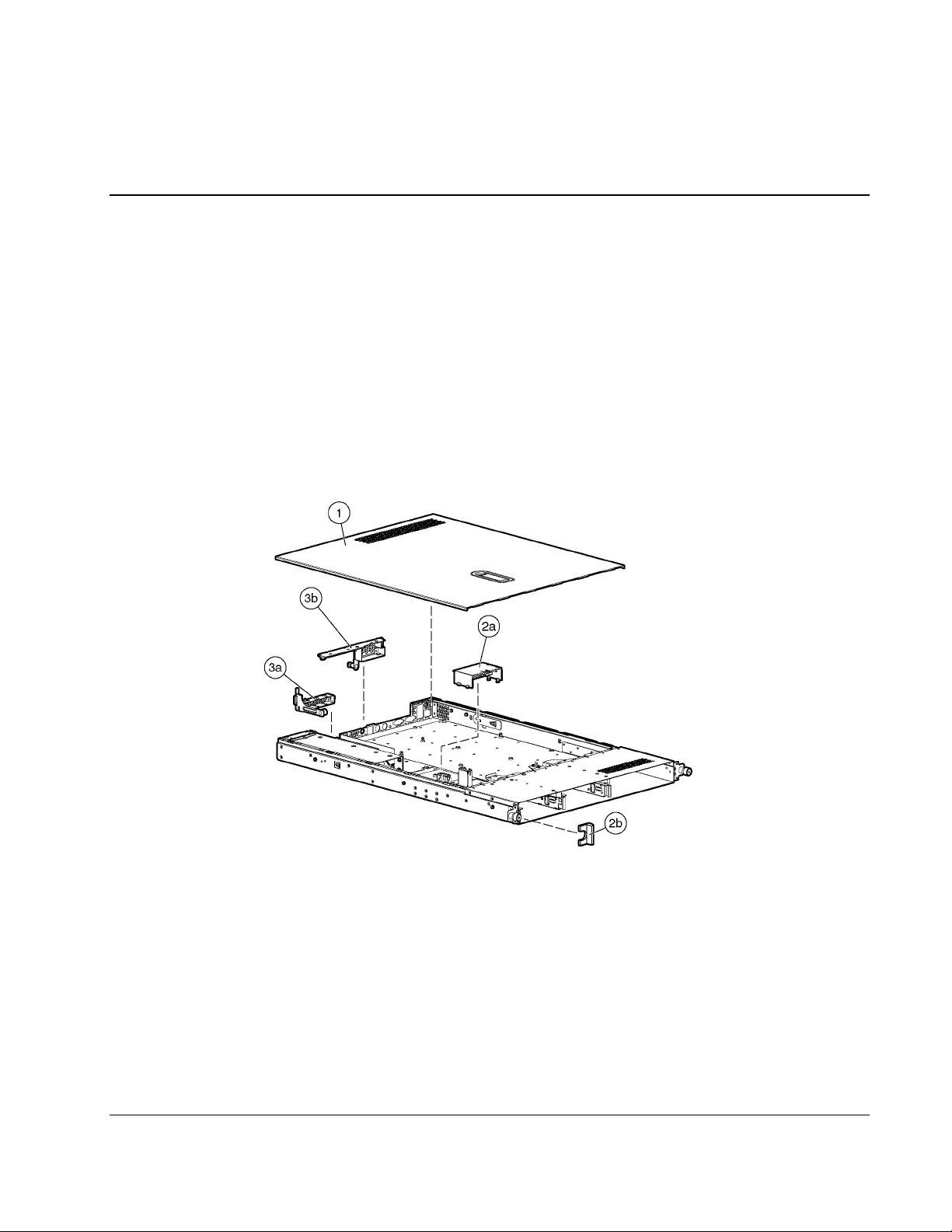
Mechanical Components Exploded View
1
Figure 1-1: Mechanical components exploded view
HP ProLiant DL360 Generation 3 Server Maintenance and Service Guide 1-1
HP CONFIDENTIAL Codename: M-ERTL Part Number: 293948-003 Last Saved On: 9/18/03 9:26 AM
Illustrated Parts Catalog
Table 1-1: Mechanical Components Spare Parts List
Item Description Spare Part Number
1 Access panel 307526-001
2
3
Plastics kit
a) Power supply fan baffle
b) Left bezel
Hardware kit
a) Power supply blank
b) PCI blank
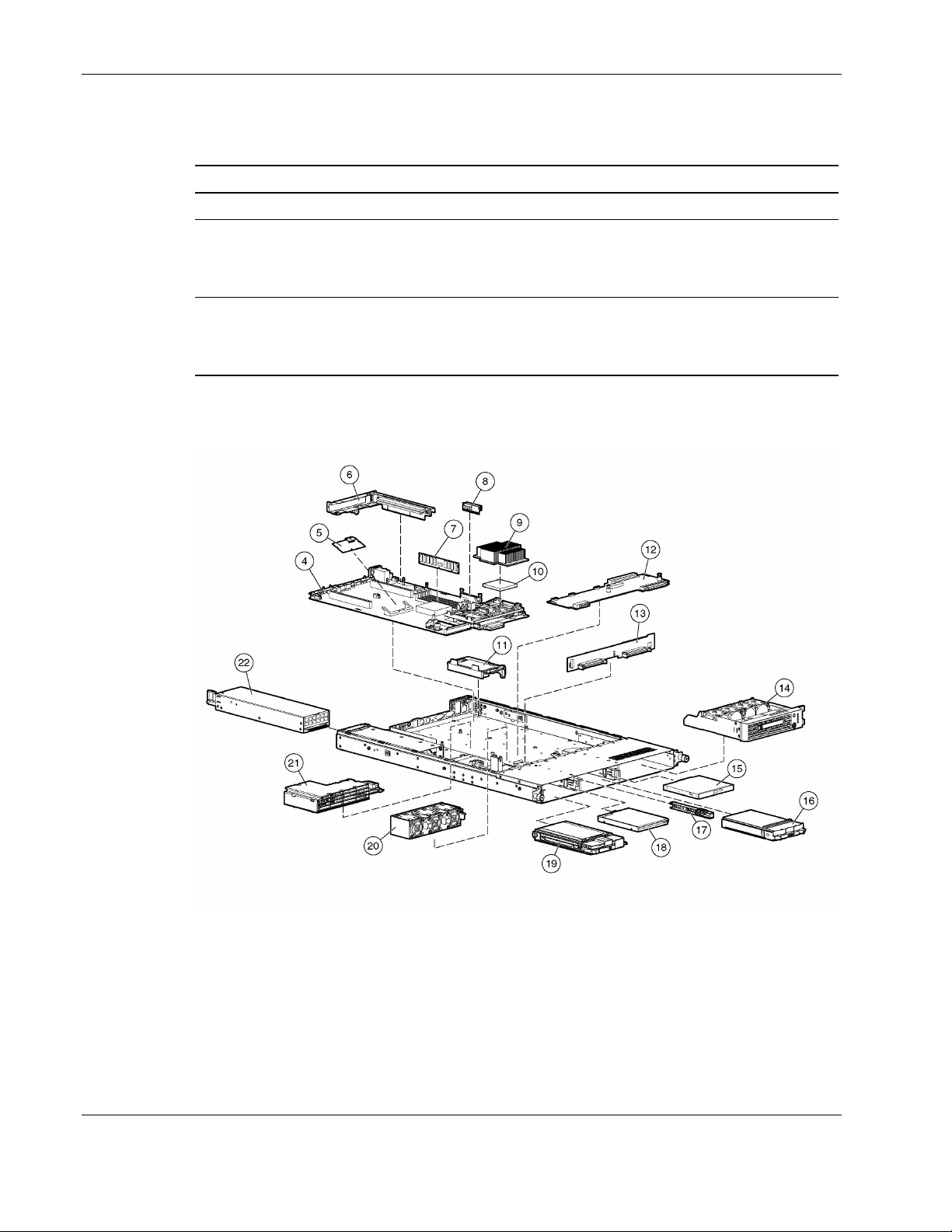
System Components Exploded View
305451-001
305452-001
Figure 1-2: System components exploded view
1-2 HP ProLiant DL360 Generation 3 Server Maintenance and Service Guide
HP CONFIDENTIAL Codename: M-ERTL Part Number: 293948-003 Last Saved On: 9/18/03 9:26 AM

System Components Spare Parts List
Table 1-2: System Components Spare Parts List
Item Description Spare Part Number
4 System board 305439-001
5 SmartArray 5i plus memory module 260741-001
6 PCI riser board assembly 305442-001
7
a) 256-MB PC2100 266-MHz DDR SDRAM DIMM 300699-001
b) 512-MB PC2100 266-MHz DDR SDRAM DIMM* 300700-001
c) 1-GB PC2100 266-MHz DDR SDRAM DIMM* 300701-001
d) 2-GB PC2100 266-MHz DDR SDRAM DIMM* 300702-001
8 Processor power module 305445-001
9 Heatsink 305448-001
10
a) 2.40-GHz, 533-MHz, 512-K cache processor 305438-001
b) 2.80-GHz, 533-MHz, 512-K cache processor * 305437-001
c) 3.06-GHz, 533-MHz, 512-K cache processor * 325148-001
d) 3.06-GHz, 533-MHz, 1-MB cache processor * 341764-001
e) 3.20-GHz, 533-MHz, 1-MB cache processor * 349335-001
(Reserved)
11 Battery-backed write cache battery module 260740-001
12 Optical device/diskette drive interface board 305450-001
13 SCSI backplane board 305443-001
14 Processor fan module 305449-001
15
a) CD-ROM drive 228508-001
b) DVD-ROM drive* 268795-001
16 Hard drive blank 313046-001
17 Optical drive ejector 305451-001
18 Diskette drive 305440-001
19
a) 18-GB, 15-K hard drive* 289240-001
b) 36-GB, 10-K hard drive* 289041-001
c) 36-GB, 15-K hard drive* 289241-001
DIMM
Processor with heatsink
Optical device
U320 SCSI hard drive
Illustrated Parts Catalog
continued
HP ProLiant DL360 Generation 3 Server Maintenance and Service Guide 1-3
HP CONFIDENTIAL Codename: M-ERTL Part Number: 293948-003 Last Saved On: 9/18/03 9:26 AM

Illustrated Parts Catalog
Table 1-2: System Components Spare Parts List continued
Item Description Spare Part Number
d) 72-GB, 10-K hard drive* 289042-001
f) 146-GB, 10K hard drive* 289044-001
20 System fan assembly 307525-001
21 Power converter module 305446-001
22 325-W power supply 305447-001
23 400-W DC power supply* 338887-001
24 System board battery* 234556-001
25 Country kit* 309480-001
26 Return kit* 173842-001
27 Fixed rail kit* 310619-001
28 Sliding rails and cable management solution* 310618-001
29 Telco rack mounting kit* 252367-001
30 Optical device/diskette drive cable* 305444-001
e) 72-GB, 15-K hard drive* 289243-001
* Not shown
1-4 HP ProLiant DL360 Generation 3 Server Maintenance and Service Guide
HP CONFIDENTIAL Codename: M-ERTL Part Number: 293948-003 Last Saved On: 9/18/03 9:26 AM

Removal and Replacement Procedures
This chapter provides subassembly/module-level removal and replacement procedures for the
HP ProLiant DL360 Generation 3 server. After completing all necessary removal and
replacement procedures, it is recommended that server diagnostic programs be run to verify
that all components are operating correctly.
The following diagnostic programs, from the SmartStart and Support Software CD, may be
used:
•
System Configuration Utility
•
Array Diagnostic Utility (ADU)
In addition, the Server Diagnostics program may be run. This program is available at
www.hp.com/support.
Electrostatic Discharge Information
2
A discharge of static electricity can damage static-sensitive devices or micro circuitry. Proper
packaging and grounding techniques are necessary to prevent damage. To prevent
electrostatic damage, observe the following precautions:
•
Transport products in static-safe containers such as conductive tubes, bags, or boxes.
•
Keep electrostatic-sensitive parts in their containers until they arrive at static-free
stations.
•
Cover workstations with approved static-dissipating material. Use a wrist strap connected
to the work surface and properly grounded tools and equipment.
•
Keep the work area free of nonconductive materials such as ordinary plastic assembly
aids and foam packing.
•
Always be properly grounded when touching a static-sensitive component or assembly.
•
Avoid touching pins, leads, or circuitry.
•
Always place drives PCB assembly-side down.
•
Use conductive field service tools.
HP ProLiant DL360 Generation 3 Server Maintenance and Service Guide 2-1
HP CONFIDENTIAL Codename: M-ERTL Part Number: 293948-003 Last Saved On: 9/18/03 9:30 AM
Removal and Replacement Procedures
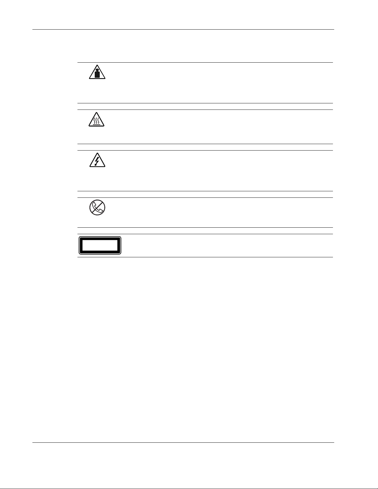
Symbols on Equipment
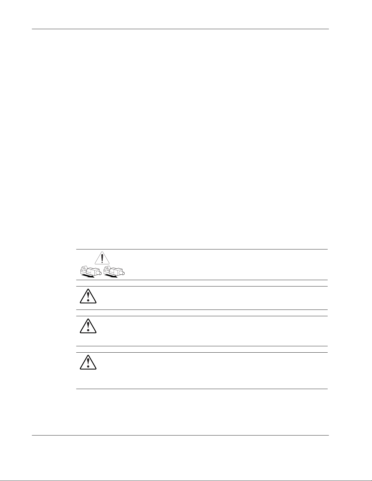
This symbol indicates that the component exceeds the recommended weight for
one individual to handle safely.
Weight in kg
Weight in lb
WARNING: To reduce the risk of personal injury or damage to the equipment,
observe local occupational health and safety requirements and guidelines for
manual material handling.
This symbol indicates the presence of a hot surface or hot component. If this
surface is contacted, the potential for injury exists.
WARNING: To reduce the risk of injury from a hot component, allow the surface
to cool before touching.
This symbol indicates the presence of hazardous energy circuits or electric
shock hazards. Refer all servicing to qualified personnel.
WARNING: To reduce the risk of injury from electric shock hazards, do not open
this enclosure. Refer all maintenance, upgrades, and servicing to qualified
personnel.
This symbol on an RJ-45 receptacle indicates a network interface connection.
WARNING: To reduce the risk of electric shock, fire, or damage to the equipment,
do not plug telephone or telecommunications connectors into this receptacle.
CLASS 1 LASER PRODUCT
This label or equivalent is located on the surface of your CD-ROM drive. This label
indicates that the product is classified as a Class 1 Laser Product.
2-2 HP ProLiant DL360 Generation 3 Server Maintenance and Service Guide
HP CONFIDENTIAL Codename: M-ERTL Part Number: 293948-003 Last Saved On: 9/18/03 9:30 AM
Rack Warnings and Precautions
WARNING: To reduce the risk of personal injury or damage to equipment, always
ensure that the rack is adequately stabilized before extending a component outside the
rack. A rack may become unstable if more than one component is extended for any
reason. Extend only one component at a time.
WARNING: To reduce the risk of personal injury or damage to the equipment, be sure
that:
• The leveling jacks are extended to the floor.
• The full weight of the rack rests on the leveling jacks.
• The stabilizers are attached to the rack, if it is a single rack installation.
• The racks are coupled together in multiple rack installations.
WARNING: When installing the server in a telco rack, make certain that the rack frame
is adequately secured to the building structure at the top and bottom.
WARNING: To reduce the risk of personal injury or damage to the equipment, at least
two people are needed to safely unload the rack from the pallet. An empty 42U rack
weighs 115 kg (253 lb), is over 2.1m (7 ft) tall, and may become unstable when being
moved on its casters. Do not stand in front of the rack as it rolls down the ramp from
the pallet, but handle the rack from both sides.
Removal and Replacement Procedures
Server Warnings and Precautions
WARNING: To reduce the risk of personal injury from hot surfaces, allow the hot-plug
drives and the internal system components to cool before touching.
WARNING: To reduce the risk of electric shock or damage to the equipment:
• Do not disable the power cord grounding plug. The grounding plug is an important
safety feature.
• Plug the power cord into a grounded (earthed) electrical outlet that is easily
accessible at all times.
• Unplug the power cord from each power supply to disconnect power to the
equipment.
CAUTION: Protect the server from power fluctuations and temporary interruptions with a
regulating uninterruptible power supply (UPS). This device protects the hardware from
damage caused by power surges and voltage spikes and keeps the system in operation
during a power failure.
CAUTION: HP servers
Proper cooling will not be achieved if the system access panel is removed.
must always be operated with the system access panel closed.
HP ProLiant DL360 Generation 3 Server Maintenance and Service Guide 2-3
HP CONFIDENTIAL Codename: M-ERTL Part Number: 293948-003 Last Saved On: 9/18/03 9:30 AM
Removal and Replacement Procedures
Preparation Procedures
Before removing any serviceable parts, determine whether the part is a hot-plug device or a
non-hot-plug device.
Hot-Plug Devices
The hot-plug devices on ProLiant DL360 Generation 3 servers are the U320 SCSI hard drives
and power supplies. U320 SCSI hard drives and power supplies can be serviced without
removing the server from the rack.
IMPORTANT: It is not necessary to turn off the server to replace hot-plug hard drives.
Non-Hot-Plug Devices
Optical devices can be replaced with the server power in standby mode and can be replaced
without the need to remove the server from the rack.
To service all other non-hot-plug devices, the server must be powered down completely and
removed from the rack.
Powering Down the Server
Prior to performing most kinds of maintenance, it is necessary to power down the server.
WARNING: To reduce the risk of injury from electric shock, remove the
power cord to completely disconnect power from the system.
WARNING: To reduce the risk of personal injury or damage to the equipment, ensure
that only one component is extended at a time. A rack may become unstable if more
than one component is extended for any reason.
WARNING: Because the rack allows you to stack computer components in a vertical
rather than a horizontal plane, you must take precautions to provide for rack stability
and safety to protect both personnel and property. Heed all cautions and warnings
throughout the installation instructions that came with the server.
WARNING: To reduce the risk of personal injury or damage to the equipment: If the
server is removed from the rack for device accessibility, remove the server from the
rack and place it on a sturdy table or workbench. Refer to the HP ProLiant DL360
Generation 3 Setup and Installation Guide for further information on working with
racks.
2-4 HP ProLiant DL360 Generation 3 Server Maintenance and Service Guide
HP CONFIDENTIAL Codename: M-ERTL Part Number: 293948-003 Last Saved On: 9/18/03 9:30 AM
Removal and Replacement Procedures
CAUTION: The system power in the server does not completely shut off from the front
Power On/Standby switch. Moving the switch from On to Standby leaves some portion of the
power supply and some internal circuitry active. Disconnect all power cords from the server to
remove all power from the system.
CAUTION: Electrostatic discharge may damage electronic components. Be sure you are
properly grounded before beginning any installation procedure. For more information, refer to
“Electrostatic Discharge Information” earlier in this chapter.
To power down the server:
1. Shut down the operating system as directed in the operating system instructions.
CAUTION: Whenever installing hardware or performing maintenance
procedures requiring access to internal components, it is recommended that all
server data be backed up to avoid loss.
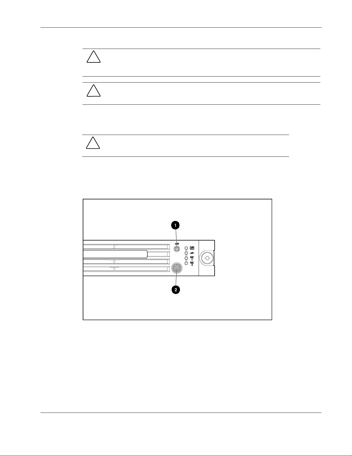
2. Press the Unit Identification switch on the server front panel (1). An LED illuminates
blue on the server front and rear panels.
3. Press the server Power On/Standby switch (2) to power down the server. The Power
On/Off LED (2) changes from green to amber, indicating standby mode.
Figure 2-1: Activating the Front Unit Identification LED and
powering down the server
HP ProLiant DL360 Generation 3 Server Maintenance and Service Guide 2-5
HP CONFIDENTIAL Codename: M-ERTL Part Number: 293948-003 Last Saved On: 9/18/03 9:30 AM
Removal and Replacement Procedures
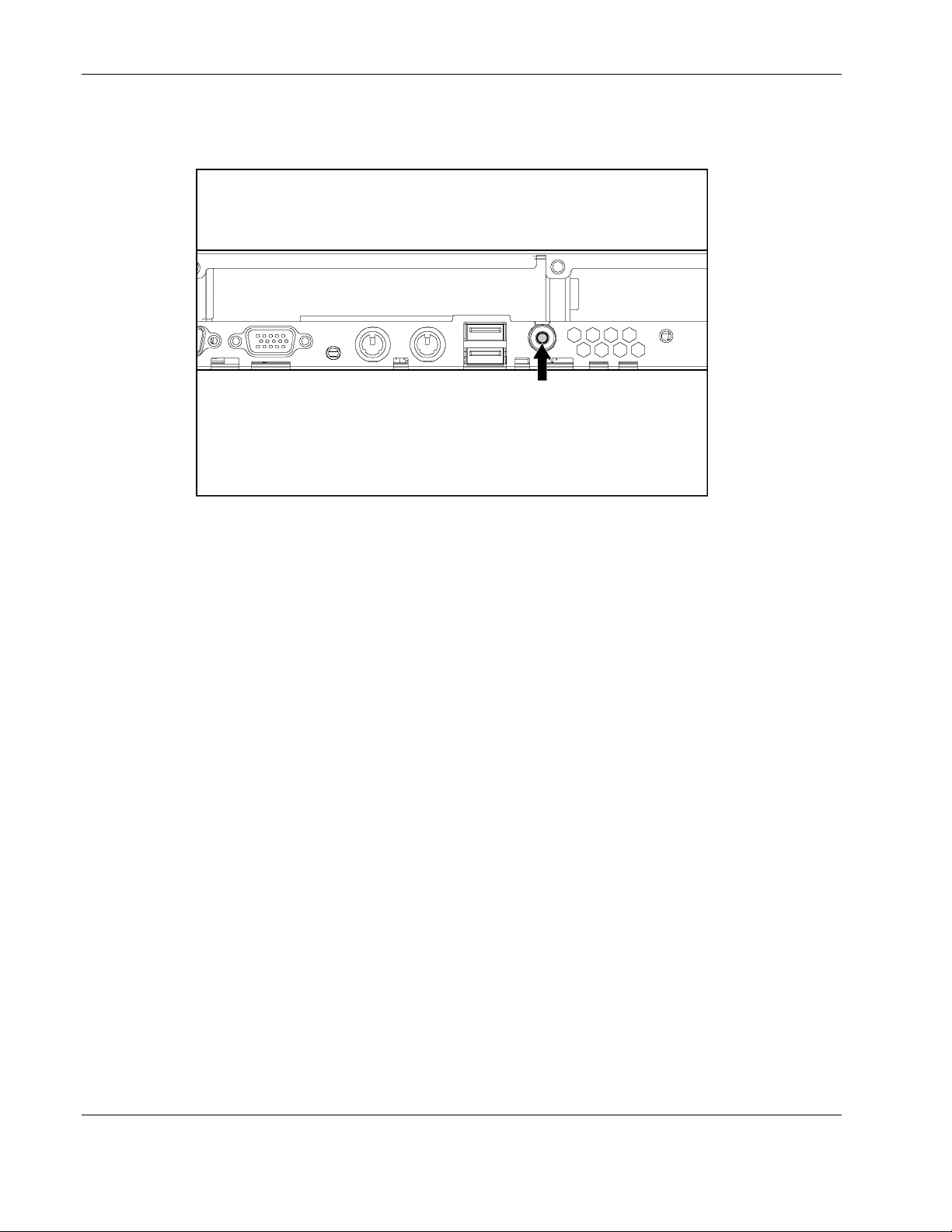
4. At the rear of the server, locate the illuminated Rear Unit Identification LED switch that
identifies the server being serviced.
Figure 2-2: Rear Unit Identification LED switch
5. Disconnect power cord(s).
Removing the Server from the Rack
To remove the server from the rack:
1. If the server has a sliding rail solution:
a. Disconnect all remaining cables from the server rear panel (including cables
extending from expansion boards).
b. Loosen the thumbscrews securing the server to the rack.
c. Slide the server out of the rack until the rail locks engage.
d. Press and hold the rail locks, extend the server until it clears the rack.
2. If the server has a universal rail solution:
a. Disconnect all remaining cables from the server rear panel (including cables
extending from expansion boards), moving from left to right.
2-6 HP ProLiant DL360 Generation 3 Server Maintenance and Service Guide
HP CONFIDENTIAL Codename: M-ERTL Part Number: 293948-003 Last Saved On: 9/18/03 9:30 AM
Removal and Replacement Procedures
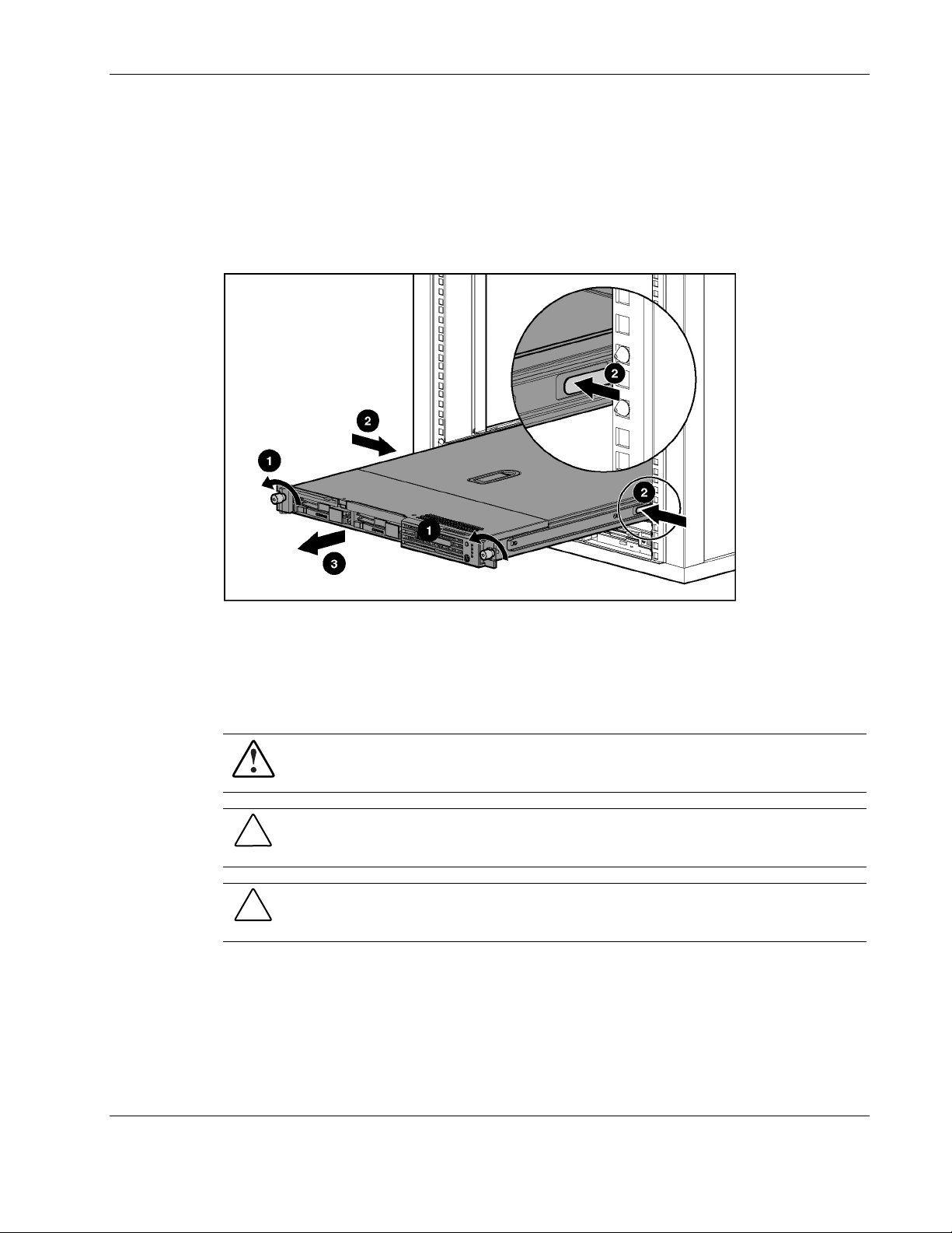
b. Move to the front of the rack and loosen the thumbscrews securing the server to the
rack (1).
c. Grasp the front panel thumbscrews, and extend the server from the rack. The cables
remain clamped in the cable tray. The rail release latches engage automatically.
d. Press in and hold the rail release latches (2).
e. Extend the server completely out of the rack (3), and set it on a flat, level surface.
Figure 2-3: Removing the server from the rack
Reverse these procedures to replace the server into the rack.
Server Access Panel
WARNING: To reduce the risk of personal injury from hot surfaces, allow the internal
system components to cool before touching them.
CAUTION: Before removing the server access panel, be sure that the server is powered
down and that the power cord is disconnected from the server or the electrical outlet.
CAUTION: Electrostatic discharge can damage electronic components. Be sure you are
properly grounded before beginning any installation procedure.
HP ProLiant DL360 Generation 3 Server Maintenance and Service Guide 2-7
HP CONFIDENTIAL Codename: M-ERTL Part Number: 293948-003 Last Saved On: 9/18/03 9:30 AM
Removal and Replacement Procedures
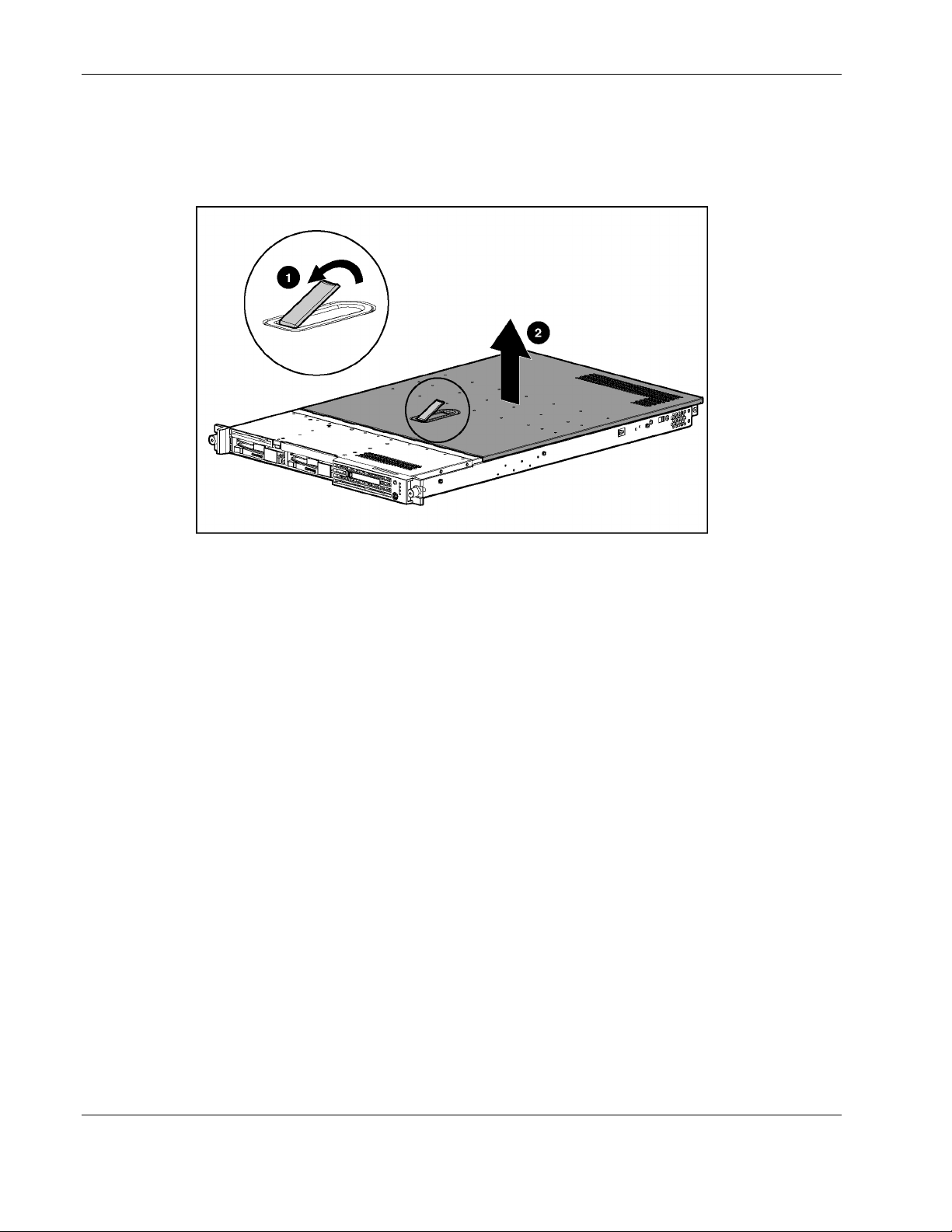
To remove the access panel:
1. Lift up on the hood latch (1). The access panel will slide toward the back of the chassis.
2. Lift up to remove the access panel (2).
Figure 2-4: Removing the server access panel
Reverse steps 1 and 2 to replace the access panel.
Processor Fan Module
To remove the processor fan module:
1. Power down the server. Refer to “Powering Down the Server” earlier in this chapter.
2. Remove the server from the rack. Refer to “Removing the Server from the Rack” earlier
in this chapter.
3. Remove the access panel. Refer to “Server Access Panel” earlier in this chapter.
2-8 HP ProLiant DL360 Generation 3 Server Maintenance and Service Guide
HP CONFIDENTIAL Codename: M-ERTL Part Number: 293948-003 Last Saved On: 9/18/03 9:30 AM
Removal and Replacement Procedures
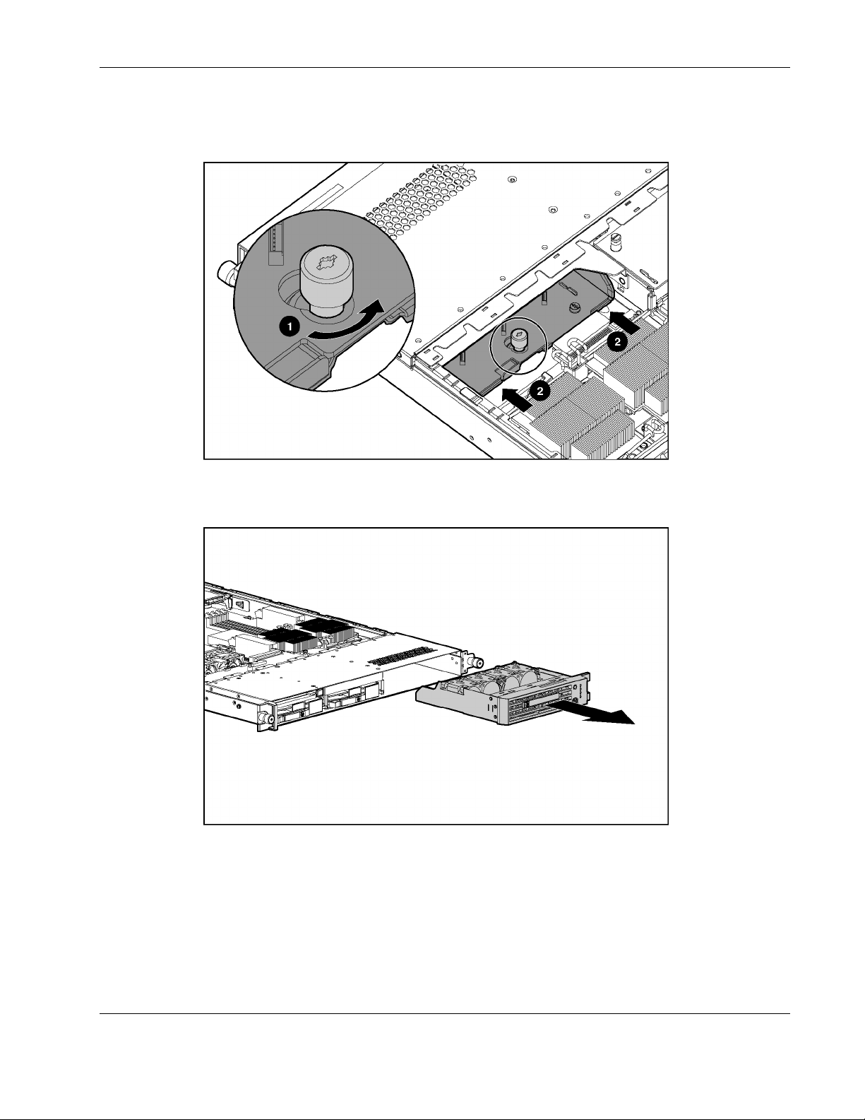
4. Loosen the thumbscrew (1) securing the processor fan module to the chassis.
5. Press the processor fan module from the rear (2) to release it from the system board.
Figure 2-5: Loosening the processor fan module thumbscrew
6. Remove the processor fan module from the chassis.
Figure 2-6: Removing the processor fan module
Reverse steps 1 through 6 to install the processor fan module.
HP ProLiant DL360 Generation 3 Server Maintenance and Service Guide 2-9
HP CONFIDENTIAL Codename: M-ERTL Part Number: 293948-003 Last Saved On: 9/18/03 9:30 AM
Removal and Replacement Procedures
Mass Storage Devices
The ProLiant DL360 Generation 3 server can support the following mass storage devices:
•
(Up to) Two hot-plug U320 SCSI hard drives
•
A low-profile optical device
•
A low-profile, 3.5-inch, 1.44-MB diskette drive
This section describes the drive cage positions and removal and replacement procedures for
these mass storage devices.
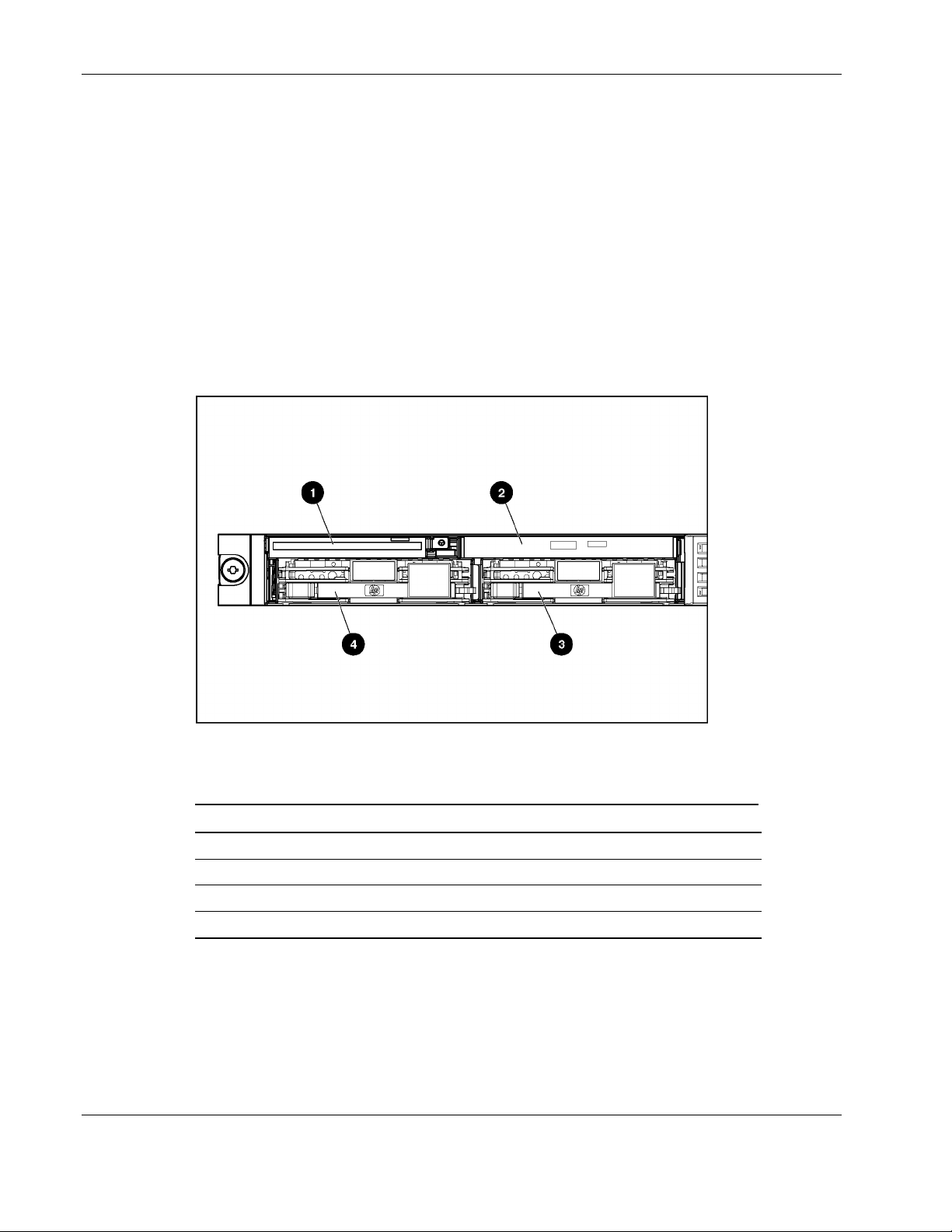
Drive Locations
Figure 2-7: Server drive locations
Table 2-1: Server Drive Locations
Location Description
1 Low-profile 3.5-inch, 1.44-MB diskette drive
2 Low-profile optical device
3 Hot-plug U320 SCSI hard drive, SCSI ID 0
4 Hot-plug U320 SCSI hard drive, SCSI ID 1
2-10 HP ProLiant DL360 Generation 3 Server Maintenance and Service Guide
HP CONFIDENTIAL Codename: M-ERTL Part Number: 293948-003 Last Saved On: 9/18/03 9:30 AM
Hard Drive Blank
To remove a hard drive blank:
1. Press the release button (1).
2. Pull the blank out of the drive bay (2).
Removal and Replacement Procedures
CAUTION: Do not operate the server without a hard drive or a hard drive blank installed.
Failure to install a hard drive or a hard drive blank can lead to improper cooling and may
damage the system.
Figure 2-8: Removing a hard drive blank
To replace the hard drive blank, slide the blank into the bay until it locks into place.
Hot-Plug U320 SCSI Hard Drives
To assess a hard drive’s status, you must observe and understand the hot-plug hard drive
status LEDs. For a detailed explanation of hard drive status LEDs, refer to the HP ProLiant
DL360 Generation 3 Server Setup and Installation Guide.
WARNING: Read “Hot-plug Hard Drive Replacement Guidelines” in the Servers
Troubleshooting Guide prior to removing a hard drive.
CAUTION: Do not operate the server without a hard drive or a hard drive blank installed.
Failure to install a hard drive or a hard drive blank can lead to improper cooling and may
damage the system.
HP ProLiant DL360 Generation 3 Server Maintenance and Service Guide 2-11
HP CONFIDENTIAL Codename: M-ERTL Part Number: 293948-003 Last Saved On: 9/18/03 9:30 AM

Removal and Replacement Procedures
To remove a hot-plug U320 SCSI hard drive:
1. Press the button on the hard drive to release the drive latch (1).
2. Open the drive latch on the hard drive (2).
3. Pull the hard drive to remove it from the server (3).
Figure 2-9: Removing a hot-plug U320 SCSI hard drive
IMPORTANT: The ProLiant DL360 Generation 3 server supports HP Universal U320 drives only.
Compaq branded Ultra3 or HP branded U160 hot-plug drives are not supported.
2-12 HP ProLiant DL360 Generation 3 Server Maintenance and Service Guide
HP CONFIDENTIAL Codename: M-ERTL Part Number: 293948-003 Last Saved On: 9/18/03 9:30 AM

Removal and Replacement Procedures
To replace the hard drive:
1. Slide the hard drive into the open bay (1).
2. Close the drive latch to secure the hard drive into the server (2).
Figure 2-10: Installing a hot-plug U320 SCSI hard drive
Optical Device
The server supports a diskette drive and an optical device. The optical device and the diskette
drive may be removed independently.
CAUTION: Do not operate the server without an optical device installed. Failure to install an
optical device can lead to improper cooling and may damage the system.
HP ProLiant DL360 Generation 3 Server Maintenance and Service Guide 2-13
HP CONFIDENTIAL Codename: M-ERTL Part Number: 293948-003 Last Saved On: 9/18/03 9:30 AM

Removal and Replacement Procedures
To remove the optical device:
1. Press the Power On/Standby switch to place the server in standby mode. Refer to
“Powering Down the Server” earlier in this chapter.
2. Push the optical device ejector button to release the optical device (1).
NOTE: Access to the optical device ejector button is intentionally restricted. Push the optical
device ejector button with a small flat object such as a key or pen to eject the optical drive.
3. Grasp the optical device and remove it from the optical device bay (2).
Figure 2-11: Removing the optical device
2-14 HP ProLiant DL360 Generation 3 Server Maintenance and Service Guide
HP CONFIDENTIAL Codename: M-ERTL Part Number: 293948-003 Last Saved On: 9/18/03 9:30 AM

Removal and Replacement Procedures
To replace the optical device:
1. Align the optical device with the optical device bay and slide the device into the chassis
until it is fully seated.
Figure 2-12: Aligning and installing the optical device
2. Press the Power/On Standby switch to power on the server, and resume normal
operations.
Optical Device Ejector
To remove the optical device ejector:
1. Power down the server. Refer to “Powering Down the Server” earlier in this chapter.
2. Remove the optical device. Refer to “Optical Device” earlier in this chapter.
3. Remove all hard drive blanks and hot-plug U320 SCSI hard drives. Refer to “Hard Drive
Blank” and “Hot-Plug U320 SCSI Hard Drives” earlier in this chapter.
4. Partially extend the server to gain access to the screws securing the optical device ejector
to the chassis.
HP ProLiant DL360 Generation 3 Server Maintenance and Service Guide 2-15
HP CONFIDENTIAL Codename: M-ERTL Part Number: 293948-003 Last Saved On: 9/18/03 9:30 AM

Removal and Replacement Procedures
5. Remove the screws securing the optical device ejector to the chassis.
Figure 2-13: Removing optical device ejector screws
6. Press the tab on the side of the optical device ejector (1) to release it from the chassis.
NOTE: Access to the tab on the side of the optical device ejector is restricted. To push in the tab
on the optical device ejector, use a small flat object such as a key, screwdriver, or pen.
7. Lower the optical device ejector and remove it from the chassis (2).
Figure 2-14: Removing the optical device ejector from the chassis
2-16 HP ProLiant DL360 Generation 3 Server Maintenance and Service Guide
HP CONFIDENTIAL Codename: M-ERTL Part Number: 293948-003 Last Saved On: 9/18/03 9:30 AM

Removal and Replacement Procedures
8. Press the tab on the side of the optical device ejector (1).
9. Slide the optical device ejector into the slot in the chassis (2) until the tab clicks in to
place.
Figure 2-15: Inserting the optical device ejector into the chassis
10. Replace the screws securing the optical device ejector to the chassis.
Figure 2-16: Replacing the optical device ejector screws
HP ProLiant DL360 Generation 3 Server Maintenance and Service Guide 2-17
HP CONFIDENTIAL Codename: M-ERTL Part Number: 293948-003 Last Saved On: 9/18/03 9:30 AM

Removal and Replacement Procedures
Diskette Drive
To remove the diskette drive:
CAUTION: Do not operate the server without a diskette drive installed. Failure to install a
diskette drive can lead to improper cooling and may damage the system.
1. Power down the server. Refer to “Powering Down the Server” earlier in this chapter.
2. Remove the server from the rack. Refer to “Removing the Server from the Rack” earlier
in this chapter.
3. Remove the access panel. Refer to “Server Access Panel” earlier in this chapter.
4. Remove the hot-plug U320 SCSI hard drive located below the diskette drive. Refer to
“Hot-Plug U320 SCSI Hard Drives” earlier in this chapter.
5. Remove the diskette drive retaining screw (1).
6. Push the diskette drive from the rear to release it from the backplane connector, and pull
the diskette drive out of the chassis (2).
Figure 2-17: Removing the diskette drive
2-18 HP ProLiant DL360 Generation 3 Server Maintenance and Service Guide
HP CONFIDENTIAL Codename: M-ERTL Part Number: 293948-003 Last Saved On: 9/18/03 9:30 AM

To replace the diskette drive:
1. Slide the diskette drive into the open bay (1).
2. Replace the diskette drive retaining screw (2).
Figure 2-18: Installing the diskette drive
Removal and Replacement Procedures
3. Replace the hot-plug U320 SCSI hard drive. Refer to “Hot-Plug U320 SCSI Hard
Drives” earlier in this chapter.
4. Replace the access panel. Refer to “Server Access Panel” earlier in this chapter.
5. Replace the server in the rack. Refer to “Removing the Server from the Rack” earlier in
this chapter.
6. Connect the power cord(s).
7. Press the Power On/Standby switch to power on the server and resume normal
operations.
Hot-Plug Power Supplies
The procedures in this section assume that the server is configured with two power supplies.
To remove a power supply:
1. Disconnect the power cord.
HP ProLiant DL360 Generation 3 Server Maintenance and Service Guide 2-19
HP CONFIDENTIAL Codename: M-ERTL Part Number: 293948-003 Last Saved On: 9/18/03 9:30 AM

Removal and Replacement Procedures
2. If you are removing the power supply from hot-plug power supply bay 1, and there is a
sliding rail solution in place:
a. Loosen the cable retractor thumbscrew (1).
b. Pull the cable retractor back, away from the server chassis, and then away from the
rack rail (2).
Figure 2-19: Moving the cable retractor to access the power supply
in hot-plug power supply bay 1 (cables removed for clarity)
3. Grasp the handle on the power supply.
4. Push the power supply ejector button (1).
5. Pull the power supply from the server (2).
Figure 2-20: Removing a power supply (cables removed for clarity)
2-20 HP ProLiant DL360 Generation 3 Server Maintenance and Service Guide
HP CONFIDENTIAL Codename: M-ERTL Part Number: 293948-003 Last Saved On: 9/18/03 9:30 AM

Removal and Replacement Procedures
To install a hot-plug power supply:
1. Remove the protective cover from the connector on the power supply.
2. Slide the power supply into the chassis until it snaps into place.
Figure 2-21: Installing a power supply (cables removed for clarity)
3. If you are replacing the power supply from hot-plug power supply bay 1, and there is a
sliding rail solution in place:
a. Push the cable retractor toward the rack rail and toward the chassis (1).
b. Tighten the cable retractor thumbscrew (2).
Figure 2-22: Returning the cable retractor (cables removed for
clarity)
HP ProLiant DL360 Generation 3 Server Maintenance and Service Guide 2-21
HP CONFIDENTIAL Codename: M-ERTL Part Number: 293948-003 Last Saved On: 9/18/03 9:30 AM

Removal and Replacement Procedures
4. Connect the power cord.
PCI Riser Board Assembly
The procedures in this section assume that the server is configured with two PCI riser board
assemblies.
To remove the PCI riser board assembly:
1. Power down the server. Refer to “Powering Down the Server” earlier in this chapter.
2. Remove the server from the rack. Refer to “Removing the Server from the Rack” earlier
in this chapter.
3. Remove the access panel. Refer to “Server Access Panel” earlier in this chapter.
4. Loosen the PCI riser board thumbscrew (1).
5. Lift the front of the assembly slightly (2), and then pull it out from the server chassis PCI
expansion board slot (3).
Figure 2-23: Removing the PCI riser board assembly
Reverse steps 1 through 5 to replace the PCI riser board assembly.
Replacing an Expansion Board
To replace an expansion board:
1. Power down the server. Refer to “Powering Down the Server” earlier in this chapter.
2. Remove the server from the rack. Refer to “Removing the Server from the Rack” earlier
in this chapter.
3. Remove the access panel. Refer to “Server Access Panel” earlier in this chapter.
2-22 HP ProLiant DL360 Generation 3 Server Maintenance and Service Guide
HP CONFIDENTIAL Codename: M-ERTL Part Number: 293948-003 Last Saved On: 9/18/03 9:30 AM

Removal and Replacement Procedures
4. Remove the appropriate PCI riser board assembly. Refer to “PCI Riser Board Assembly”
earlier in this chapter.
5. Slide the expansion board out of the slot.
Figure 2-24: Removing an expansion board from the PCI riser
board assembly
6. Align the expansion board with the guiding groove.
7. Slide the expansion board into the slot until the board firmly seats.
Figure 2-25: Installing an expansion board into the PCI riser board
assembly
8. Install the PCI riser board assembly into the appropriate PCI expansion board slot. Refer
to “PCI Riser Board Assembly” earlier in this chapter.
HP ProLiant DL360 Generation 3 Server Maintenance and Service Guide 2-23
HP CONFIDENTIAL Codename: M-ERTL Part Number: 293948-003 Last Saved On: 9/18/03 9:30 AM

Removal and Replacement Procedures
I/O System Fan Assembly
To remove the I/O system fan assembly:
1. Power down the server. Refer to “Powering Down the Server” earlier in this chapter.
2. Remove the server from the rack. Refer to “Removing the Server from the Rack” earlier
in this chapter.
3. Remove the access panel. Refer to “Server Access Panel” earlier in this chapter.
4. Remove the PCI riser board assembly. Refer to “PCI Riser Board Assembly” earlier in
this chapter.
5. Disconnect the fan power cables from the optical device/diskette drive interface
board (1).
6. Disconnect the optical device/diskette drive interface board power cable from the optical
device/diskette drive interface board (2).
7. Remove the optical device/diskette drive interface board power cable from the clip on the
side of the I/O fan assembly (3).
Figure 2-26: Disconnecting cables from the optical device/diskette
drive interface board
2-24 HP ProLiant DL360 Generation 3 Server Maintenance and Service Guide
HP CONFIDENTIAL Codename: M-ERTL Part Number: 293948-003 Last Saved On: 9/18/03 9:30 AM

Removal and Replacement Procedures
8. Press in the retaining clips on either side of the I/O system fan assembly (1) and lift the
assembly from the chassis (2).
Figure 2-27: Removing the I/O system fan assembly
Reverse steps 1 through 8 to replace the fan assembly.
Power Converter Module
To remove the power converter module:
1. Power down the server. Refer to “Powering Down the Server” earlier in this chapter.
2. Remove the server from the rack. Refer to “Removing the Server from the Rack” earlier
in this chapter.
3. Remove the access panel. Refer to “Server Access Panel” earlier in this chapter.
HP ProLiant DL360 Generation 3 Server Maintenance and Service Guide 2-25
HP CONFIDENTIAL Codename: M-ERTL Part Number: 293948-003 Last Saved On: 9/18/03 9:30 AM

Removal and Replacement Procedures
4. If your server is configured with hot-plug power supplies:
a. Remove both hot-plug power supplies. Refer to “Hot-Plug Power Supplies” earlier in
this chapter.
b. Press down on the tab on the power supply fan baffle (1).
c. Slide the baffle toward the back of the chassis, and remove it (2).
Figure 2-28: Removing the power supply fan baffle
5. If your server is configured with a PCI riser board assembly in PCI expansion board
slot 2:
a. Remove the hot-plug power supply. Refer to “Hot-Plug Power Supplies” earlier in
this chapter.
b. Remove the PCI riser board assembly from PCI expansion board slot 2. Refer to
“PCI Riser Board Assembly” earlier in this chapter.
2-26 HP ProLiant DL360 Generation 3 Server Maintenance and Service Guide
HP CONFIDENTIAL Codename: M-ERTL Part Number: 293948-003 Last Saved On: 9/18/03 9:30 AM

Removal and Replacement Procedures
6. Disconnect the optical device/diskette drive interface board power cable (1).
7. Remove the optical device/diskette drive interface board power cable from the clip on the
side of the I/O fan assembly (2).
Figure 2-29: Disconnecting the optical device/diskette drive
interface board power cable
8. Loosen the thumbscrew securing the power converter module to the chassis (1).
9. Slide the power converter module toward the rear of the chassis and remove it (2).
Figure 2-30: Removing the power converter module from the
chassis
HP ProLiant DL360 Generation 3 Server Maintenance and Service Guide 2-27
HP CONFIDENTIAL Codename: M-ERTL Part Number: 293948-003 Last Saved On: 9/18/03 9:30 AM

Removal and Replacement Procedures
10. While holding the power converter, disconnect the power supply signal cable and the
system power cable from the system board.
Figure 2-31: Disconnecting the power supply signal cable and the
system power cable from the system board
Reverse steps 1 through 10 to replace the power converter module.
Optical Device/Diskette Drive Interface Board
To remove the optical device/diskette drive interface board:
1. Power down the server. Refer to “Powering Down the Server” earlier in this chapter.
2. Remove the server from the rack. Refer to “Removing the Server from the Rack” earlier
in this chapter.
3. Remove the access panel. Refer to “Server Access Panel” earlier in this chapter.
4. Remove the optical device and diskette drives. Refer to “Optical Device” and “Diskette
Drive” earlier in this chapter.
2-28 HP ProLiant DL360 Generation 3 Server Maintenance and Service Guide
HP CONFIDENTIAL Codename: M-ERTL Part Number: 293948-003 Last Saved On: 9/18/03 9:30 AM

Removal and Replacement Procedures
5. Disconnect the I/O system fan assembly power cables (1) and the optical device/diskette
drive interface board power cable (2).
Figure 2-32: Disconnecting I/O system fan assembly and power
converter module power cables
6. Disconnect the optical device/diskette drive cable (1).
7. Loosen the thumbscrews securing the interface board to the server chassis (2).
8. Pull the interface board forward, tip it, and remove it from the server chassis (3).
Figure 2-33: Removing the optical device/diskette drive interface
board from the chassis
Reverse steps 1 through 8 to replace the optical device/diskette interface board.
HP ProLiant DL360 Generation 3 Server Maintenance and Service Guide 2-29
HP CONFIDENTIAL Codename: M-ERTL Part Number: 293948-003 Last Saved On: 9/18/03 9:30 AM

Removal and Replacement Procedures
SCSI Backplane Board
To remove the SCSI backplane board:
1. Power down the server. Refer to “Powering Down the Server” earlier in this chapter.
2. Remove the server from the rack. Refer to “Removing the Server from the Rack” earlier
in this chapter.
3. Remove the access panel. Refer to “Server Access Panel” earlier in this chapter.
4. Remove the optical device/diskette drive interface board. Refer to “Optical
Device/Diskette Drive Interface Board” earlier in this chapter.
5. Lift the SCSI backplane board until it clears the server.
Figure 2-34: Removing the SCSI backplane
Reverse steps 1 through 5 to replace the SCSI backplane.
2-30 HP ProLiant DL360 Generation 3 Server Maintenance and Service Guide
HP CONFIDENTIAL Codename: M-ERTL Part Number: 293948-003 Last Saved On: 9/18/03 9:30 AM

DIMMs
Removal and Replacement Procedures
The ProLiant DL360 Generation 3 server ships standard with two Double Data Rate (DDR)
Synchronous DRAM (SDRAM) Dual Inline Memory Modules (DIMMs) installed in DIMM
sockets 1 and 2 (Bank A). Figure 2-35 and Table 2-2 show the location of the DIMM slots on
the system board.
Observe the following guidelines when installing additional memory:
•
DDR SDRAM DIMMs must be 266 MHz, PC2100, 3.3 volts, and 72-bits wide, with
Error Correction Code (ECC). No other DIMMS are compatible with the server.
•
Use only 256-MB, 512-MB, 1-GB, or 2-GB DDR SDRAM DIMMs.
•
DIMMs must be installed in pairs and be of the same size. Install DIMMs only in one
direction. Be sure to match the notch on the module with the tab on the DIMM slot.
Before seating the DIMM in the slot, ensure that the module key is fully inserted.
•
Use only HP DDR SDRAM DIMMs. DIMMs from other sources may affect data
integrity.
•
Install DDR SDRAM DIMM modules one at a time, in sequential order, starting with
DIMM socket 1.
Figure 2-35: DIMM sockets identified on the system board
Table 2-2: DIMM Socket Identification
Item Description
1A DIMM socket 1A populated
2A DIMM socket 2A populated
3B DIMM socket 3B
4B DIMM socket 4B
HP ProLiant DL360 Generation 3 Server Maintenance and Service Guide 2-31
HP CONFIDENTIAL Codename: M-ERTL Part Number: 293948-003 Last Saved On: 9/18/03 9:30 AM

Removal and Replacement Procedures
CAUTION: Electrostatic discharge may damage electronic components. Be sure you are
properly grounded before beginning any installation procedure. Refer to “Electrostatic
Discharge Information” earlier in this chapter.
IMPORTANT: A memory module can be installed only one way. Be sure to match the key slots on the
module with the tabs on the memory slot. Push the module down into the slot, ensuring that the module
is fully inserted and properly seated.
IMPORTANT: DIMMs must be installed in pairs and must be of the same size.
IMPORTANT: DIMMs must be 266 MHz, PC2100 DDR SDRAM, 3.3 volts, 72-bits wide, and ECC.
To remove a DIMM:
1. Power down the server. Refer to “Powering Down the Server” earlier in this chapter.
2. Remove the server from the rack. Refer to “Removing the Server from the Rack” earlier
in this chapter.
3. Remove the access panel. Refer to “Server Access Panel” earlier in this chapter.
4. Open the DIMM slot latches (1).
5. Lift the DIMM from the expansion socket (2).
Figure 2-36: Removing a DIMM from the expansion socket
2-32 HP ProLiant DL360 Generation 3 Server Maintenance and Service Guide
HP CONFIDENTIAL Codename: M-ERTL Part Number: 293948-003 Last Saved On: 9/18/03 9:30 AM

Removal and Replacement Procedures
To install a DIMM:
1. Align the key slot in the bottom edge of the DIMM with the tab in the expansion socket.
2. Insert the DIMM at the same angle as the DIMM socket on the system board (1).
3. Press the DIMM firmly until the latches close (2).
Figure 2-37: Installing a DDR SDRAM DIMM into the expansion
socket
HP ProLiant DL360 Generation 3 Server Maintenance and Service Guide 2-33
HP CONFIDENTIAL Codename: M-ERTL Part Number: 293948-003 Last Saved On: 9/18/03 9:30 AM

Removal and Replacement Procedures
Processors
This server can support up to two processors. Each processor has an associated processor
power module (PPM) that must be present for proper operation of the server.
Figure 2-38: Processor and PPM socket locations
Table 2-3: Processor and PPM Sockets
Item Description
1 PPM socket 1 (must always be populated)
2 Processor socket 1 (must always be populated)
3 Processor socket 2
4 PPM socket 2
Note: A PPM must be installed when a new processor is installed.
WARNING: To reduce the risk of personal injury from hot surfaces, allow the internal
system components to cool before touching.
CAUTION: Processor socket 1 must be populated at all times. Failure to follow this process
results in the system failing to boot and halting during the Power-On Self-Test (POST). This
error will result in the system not functioning properly.
2-34 HP ProLiant DL360 Generation 3 Server Maintenance and Service Guide
HP CONFIDENTIAL Codename: M-ERTL Part Number: 293948-003 Last Saved On: 9/18/03 9:30 AM

Removal and Replacement Procedures
To remove a processor:
1. Power down the server. Refer to “Powering Down the Server” earlier in this chapter.
2. Remove the server from the rack. Refer to “Removing the Server from the Rack” earlier
in this chapter.
3. Remove the access panel. Refer to “Server Access Panel” earlier in this chapter.
4. Unlatch processor heatsink retaining clips (1).
5. Remove the heatsink (2).
Figure 2-39: Removing a heatsink
HP ProLiant DL360 Generation 3 Server Maintenance and Service Guide 2-35
HP CONFIDENTIAL Codename: M-ERTL Part Number: 293948-003 Last Saved On: 9/18/03 9:30 AM

Removal and Replacement Procedures
6. Unlatch the socket locking lever (1).
7. Lift the processor from the socket (2).
Figure 2-40: Unlocking and removing a processor
CAUTION: Always use a new heatsink when replacing processors. Failure to use new
components may result in damage to the processor.
CAUTION: Make sure the processor locking lever is open before inserting the processor into
the processor socket. Attempting to insert the processor with the processor locking lever
closed may result in damage to the processor.
2-36 HP ProLiant DL360 Generation 3 Server Maintenance and Service Guide
HP CONFIDENTIAL Codename: M-ERTL Part Number: 293948-003 Last Saved On: 9/18/03 9:30 AM

To replace the processor:
1. Install the processor into the socket (1).
2. Close the processor locking lever (2).
Removal and Replacement Procedures
Figure 2-41: Installing and locking a processor in the socket
CAUTION: Heatsinks have an integrated, plastic-covered thermal pad. Remove the plastic
cover from the new heatsink to expose the adhesive side of the thermal pad before placing
the heatsink on the processor.
3. Remove the protective covering from the heatsink.
Figure 2-42: Removing the heatsink protective covering
HP ProLiant DL360 Generation 3 Server Maintenance and Service Guide 2-37
HP CONFIDENTIAL Codename: M-ERTL Part Number: 293948-003 Last Saved On: 9/18/03 9:30 AM

Removal and Replacement Procedures
4. Install the heatsink (1).
CAUTION: Before closing the heatsink retaining clip, be sure the processor socket locking
lever is closed. Do not force the lever closed; it should close without resistance. Forcing the
lever closed may result in damage to the processor socket, requiring replacement of the
system board.
5. Close the processor heatsink retaining clips (2).
Figure 2-43: Installing the heatsink onto the processor and closing
the locking latches
Processor Power Module
Each processor has an associated PPM. Figure 2-38 shows the location of the processors and
PPMs on the system board.
To replace a PPM:
1. Power down the server. Refer to “Powering Down the Server” earlier in this chapter.
2. Remove the server from the rack. Refer to “Removing the Server from the Rack” earlier
in this chapter.
3. Remove the access panel. Refer to “Server Access Panel” earlier in this chapter.
2-38 HP ProLiant DL360 Generation 3 Server Maintenance and Service Guide
HP CONFIDENTIAL Codename: M-ERTL Part Number: 293948-003 Last Saved On: 9/18/03 9:30 AM

4. Open the PPM locking latches (1).
5. Lift the PPM from the socket (2).
Figure 2-44: Removing a processor power module
Removal and Replacement Procedures
6. Install a new PPM into the socket (1).
7. Close the locking latches (2).
Figure 2-45: Installing a processor power module
NOTE: PPMs with the same part number may look different, but they are functionally equivalent.
HP ProLiant DL360 Generation 3 Server Maintenance and Service Guide 2-39
HP CONFIDENTIAL Codename: M-ERTL Part Number: 293948-003 Last Saved On: 9/18/03 9:30 AM

Removal and Replacement Procedures
Battery-Backed Write Cache Enabler
1. Power down the server. Refer to “Powering Down the Server” earlier in this chapter.
2. Remove the server from the rack. Refer to “Removing the Server from the Rack” earlier
in this chapter.
3. Remove the access panel. Refer to “Server Access Panel” earlier in this chapter.
4. Remove the PCI riser board assembly from slot 1. Refer to “PCI Riser Board Assembly”
earlier in this chapter.
5. Remove the battery module cable from the battery-backed write cache (BBWC) cable
clip (1).
6. Disconnect the BBWC cable from the SmartArray 5i Plus Controller connector (2) and
the BBWC battery module (3).
Figure 2-46: Disconnecting the battery-backed write cache cable
2-40 HP ProLiant DL360 Generation 3 Server Maintenance and Service Guide
HP CONFIDENTIAL Codename: M-ERTL Part Number: 293948-003 Last Saved On: 9/18/03 9:30 AM

Removal and Replacement Procedures
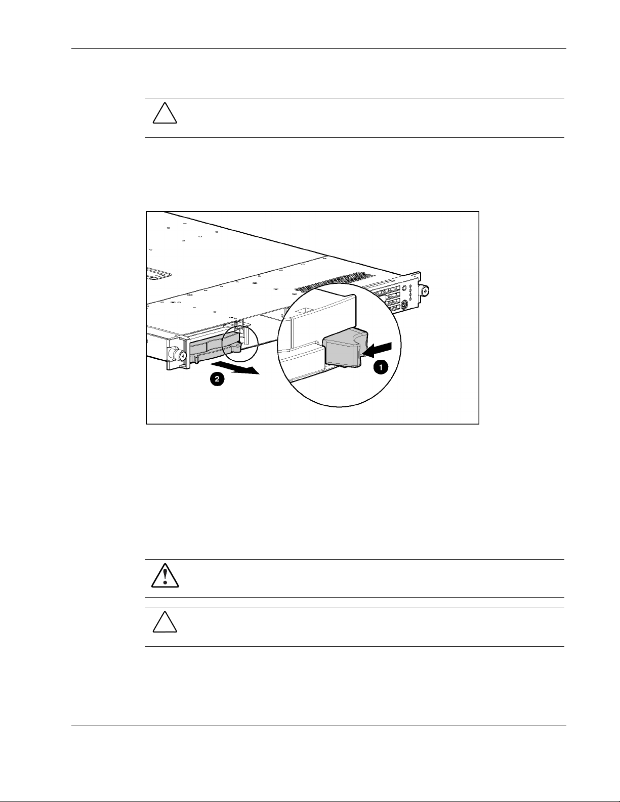
7. Pull the latch on the BBWC battery module (1).
8. Slide the BBWC battery module toward the front and away from the chassis (2), and
remove from the chassis.
Battery
Figure 2-47: Removing the BBWC battery module from the chassis
Reverse steps 1 through 8 to install the BBWC battery module.
The ProLiant DL360 Generation 3 server has one memory device that requires a battery for
retaining stored information. When your server no longer automatically displays the correct
date and time, you may need to replace the battery that provides power to the real-time clock.
With normal use, battery life is usually about 5 to 10 years. Replace used batteries with HP
540-milliampere-hour lithium, 3 V replacement batteries (P/N 179322-001).
WARNING: To reduce the risk of electric shock or equipment damage:
• Do not disable the power cord grounding plug. The grounding plug is an
important safety feature.
• Plug the power cord into a grounded (earthed) electrical outlet that is
easily accessible at all times.
• Disconnect power from the server by unplugging the power cord from
either the electrical outlet or the server.
HP ProLiant DL360 Generation 3 Server Maintenance and Service Guide 2-41
HP CONFIDENTIAL Codename: M-ERTL Part Number: 293948-003 Last Saved On: 9/18/03 9:30 AM

Removal and Replacement Procedures
To replace a battery:
1. Power down the server. Refer to “Powering Down the Server” earlier in this chapter.
2. Remove the server from the rack. Refer to “Removing the Server from the Rack” earlier
in this chapter.
3. Remove the access panel. Refer to “Server Access Panel” earlier in this chapter.
4. Remove the battery-backed write cache enabler battery pack. Refer to “Battery-Backed
Write Cache Enabler” earlier in this chapter
5. Locate the battery holder on the system board.
Figure 2-48: Battery location
6. Remove the existing battery.
Figure 2-49: Removing the system battery
2-42 HP ProLiant DL360 Generation 3 Server Maintenance and Service Guide
HP CONFIDENTIAL Codename: M-ERTL Part Number: 293948-003 Last Saved On: 9/18/03 9:30 AM

7. Reverse steps 5 and 6 to install a replacement battery.
8. Reverse steps 1 through 3 to complete the installation.
9. Run the ROM-Based Setup Utility to reconfigure the system with the new battery.
System Board
To replace the system board:
1. Power down the server. Refer to “Powering Down the Server” earlier in this chapter.
2. Remove the server from the rack. Refer to “Removing the Server from the Rack” earlier
in this chapter.
3. Remove the access panel. Refer to “Server Access Panel” earlier in this chapter.
4. Remove the processor fan module. Refer to “Processor Fan Module” earlier in this
chapter.
5. Remove the SCSI backplane board. Refer to “SCSI Backplane Board” earlier in this
chapter.
6. Remove the I/O system fan assembly. Refer to “I/O System Fan Assembly” earlier in this
chapter.
Removal and Replacement Procedures
7. Remove the power converter module. Refer to “Power Converter Module” earlier in this
chapter.
8. Loosen the system board thumbscrew (1).
9. Slide the system board toward the front of the chassis, tip it up, and remove it from the
chassis (2).
Figure 2-50: Removing the system board
Reverse steps 1 through 9 to install the system board.
HP ProLiant DL360 Generation 3 Server Maintenance and Service Guide 2-43
HP CONFIDENTIAL Codename: M-ERTL Part Number: 293948-003 Last Saved On: 9/18/03 9:30 AM

Removal and Replacement Procedures
IMPORTANT: The server serial number must be re-entered through RBSU after replacing the system
board. Refer to the “Re-entering the Server Serial Number” section.
Re-entering the Server Serial Number
After replacing the server I/O module or clearing the NVRAM, the server serial number must
be re-entered. To re-enter the serial number:
1. During the server startup sequence, press the F9 key to access RBSU.
2. Select the System Options menu.
3. Select Serial Number. The following warning is displayed:
WARNING! WARNING! WARNING! The serial number is loaded into the
system during the manufacturing process and should NOT be
modified. This option should ONLY be used by qualified service
personnel. This value should always match the serial number
sticker located on the chassis.
Press the Enter key to clear the warning.
4. Enter the serial number and press the Enter key.
5. Press the Escape key to close the menu.
6. Press the Escape key to exit RBSU.
7. Press the F10 key to confirm exiting RBSU. The server will automatically reboot.
2-44 HP ProLiant DL360 Generation 3 Server Maintenance and Service Guide
HP CONFIDENTIAL Codename: M-ERTL Part Number: 293948-003 Last Saved On: 9/18/03 9:30 AM

Server Cable Routing
CAUTION: When routing cables, always ensure that the cables are not in a
position where they will be pinched or crimped.
Figure 3-1 identifies the proper routing of the cables for the HP ProLiant DL360 Generation 3
server.
3
Cable Routing Diagram
Figure 3-1: Routing of server cables
HP ProLiant DL360 Generation 3 Server Maintenance and Service Guide 3-1
HP CONFIDENTIAL Codename: M-ERTL Part Number: 293948-003 Last Saved On: 9/18/03 9:52 AM

This chapter provides an overview of the diagnostic and management tools available for the
HP ProLiant DL360 Generation 3 server. For more detailed information and procedures, refer
to the Servers Troubleshooting Guide on the Documentation CD.
Diagnostic Tools Overview
The following tools are available to diagnose problems, test hardware, and monitor and
manage server operations.
Automatic Server Recovery-2
Automatic Server Recovery-2 (ASR-2) is a feature that causes the system to restart when a
catastrophic operating system error occurs, such as a blue screen, ABEND (abnormal end), or
panic. A system fail-safe timer, the ASR-2 timer starts when the system management driver,
also known as the health driver, is loaded. When the operating system is functioning properly,
the system periodically resets the timer. However, when the operating system fails, the timer
expires and restarts the server.
4
Diagnostic Tools
ASR-2 increases server availability by restarting the server within a specified time after a
system hang or shutdown. At the same time, the Insight Manager 7 console notifies the user
by sending a message to a designated pager number, that ASR-2 has restarted the system. The
ASR-2 can be disabled from the Insight Manager 7 console or through RBSU.
Insight Manager 7
Insight Manager 7 is a Web-based application that allows system administrators to
accomplish normal administrative tasks from any remote location, using a Web browser.
Insight Manager 7 provides device management capabilities that consolidate and integrate
management data from HP and third-party devices.
For additional information, refer to the Management CD in the ProLiant Essentials
HP ProLiant DL360 Generation 3 Server Maintenance and Service Guide 4-1
Foundation Pack.

Diagnostic Tools
Integrated Management Log
The Integrated Management Log (IML) records hundreds of events and stores them in an
easy-to-view form. The IML timestamps each event with 1-minute granularity.
Recorded events in the IML can be viewed from within:
•
Insight Manager 7
•
Survey Utility
•
Operating system-specific IML viewers
— For NetWare: IML Viewer
— For Windows: Event Viewer or IML Viewer
— For Linux: IML Viewer Application
•
Enterprise Diagnostics LX32 Utility
For more information, refer to the Servers Troubleshooting Guide on the Documentation CD,
or the Management CD in the ProLiant Essentials Foundation Pack.
Integrated Lights-Out Technology
Integrated Lights-Out (iLO) technology is a standard component of selected ProLiant servers
that provides server health and remote server manageability. The iLO subsystem includes an
intelligent microprocessor, secure memory, and a dedicated network interface. This design
makes iLO technology independent of the host server and its operating system. The iLO
subsystem provides remote access to any authorized network client, sends alerts, and
provides other server management functions.
Using iLO technology, it is possible to:
•
Remotely power up, power down, or reboot the host server.
•
Send alerts from the iLO subsystem, regardless of the state of the host server.
•
Access advanced troubleshooting features through the iLO interface.
•
Launch a Web browser and Simple Network Management Protocol (SNMP) alerting.
•
Diagnose iLO using Insight Manager 7.
For more information about iLO technology features, refer to the Integrated Lights-Out User
Guide on the Documentation CD or at
www.hp.com/servers/lights-out.
4-2 HP ProLiant DL360 Generation 3 Server Maintenance and Service Guide

Option ROM Configuration for Arrays
Before installing an operating system, use the Option ROM Configuration for Arrays
(ORCA) utility to create the first logical drive, assign RAID levels, and establish online spare
configurations.
ORCA provides support for the following functions:
•
Configuring one or more logical drives using physical drives on one or more SCSI buses
•
Viewing the current logical drive configuration
•
Deleting a logical drive configuration
ORCA will default to the standard drive configuration if none is specified.
For more information about array controller configuration, refer to the Smart Array 5i Plus
Controller and Battery-Backed Write Cache Enabler User Guide, or the ROM-Based Setup
Utility User Guide on the Documentation CD.
ProLiant Essentials Rapid Deployment Pack
Diagnostic Tools
The ProLiant Essentials Rapid Deployment Pack software is the preferred method for rapid,
high-volume server deployments. The Rapid Deployment Pack software integrates two
powerful products: Altiris eXpress Deployment Server and the ProLiant Integration Module.
The Altiris eXpress Deployment Server console’s intuitive graphical user interface provides
simplified point-and-click and drag-and-drop solutions that enable the deployment of target
servers remotely, perform imaging or scripting functions, and maintain software images.
For more information about the ProLiant Essentials Rapid Deployment Pack, refer to the
documentation that ships on the ProLiant Essentials Rapid Deployment Pack CD.
ROM-Based Setup Utility
The ROM-Based Setup Utility (RBSU) performs a wide range of configuration activities,
including the following:
•
Configuring system devices and installed options
•
Viewing system information
•
Selecting the operating system
•
Selecting the primary boot controller
•
Managing storage options
•
Configuring online spare memory
For more information on RBSU, refer to the ROM-Based Setup Utility User Guide on the
HP ProLiant DL360 Generation 3 Server Maintenance and Service Guide 4-3
Documentation CD.

Diagnostic Tools
ROMPaq Utility
Flash ROM upgrades the firmware (BIOS) with system or option ROMPaq utilities. To
upgrade the BIOS, insert a ROMPaq diskette into the diskette drive and boot the system.
The ROMPaq utility checks the system and provides a choice (if more than one exists) of
available ROM revisions. This procedure is the same for both system and option ROMPaq
utilities.
For more information about the ROMPaq utility, refer to
Smart Components for Remote ROM Flash
The Smart Components for Remote ROM Flash tool enable system administrators to
efficiently upgrade system or controller ROM images across a wide range of servers and
array controllers. This tool has the following features:
•
Works offline and online
•
Supports Microsoft Windows NT, Windows 2000, Novell NetWare, and Linux
operating systems
•
Integrates with other software maintenance, deployment, and operating system tools
•
Automatically checks for hardware, firmware, and operating system dependencies, and
installs only the correct ROM upgrades required by each target server
To download the tool and for more information, refer to
SmartStart Software
SmartStart software is a CD-based, single-server method for installing system software,
thereby achieving a well-integrated server and ensuring maximum dependability and
supportability. The SmartStart CD contains tools that diagnose problems with the server,
configure storage arrays, and update the system ROM.
www.hp.com.
www.hp.com.
4-4 HP ProLiant DL360 Generation 3 Server Maintenance and Service Guide

Diagnostic Tools
SmartStart software can:
•
Install selected server operating systems using packaged product CDs.
Install the latest optimized drivers.
•
Create and copy standard server configuration scripts using the Scripting Toolkit and
•
Configuration Replication Utility.
Test server hardware using the new Enterprise Diagnostics LX32 Utility.
•
Update the latest system or option ROM using the ROM Update Utility.
•
Install software drivers directly from the CD. With systems that have internet connection,
•
the SmartStart Autorun Menu provides access to the complete list of ProLiant System
Software on the website.
For more information about SmartStart software, refer to
SmartStart Autorun Menu
The SmartStart Autorun Menu can access the latest system software directly from the
operating system environment, simply by inserting the SmartStart CD into a configured
system. The Autorun Menu can:
Install the latest ProLiant Support Packs.
•
Download specific drivers and utilities.
•
SmartStart Scripting Toolkit
The SmartStart Scripting Toolkit is a set of Microsoft MS-DOS-based utilities that configure
and deploy servers in a customized, predictable, and unattended manner. These utilities
provide scripted server and array replication for mass server deployment and duplicate the
configuration of a source server onto target systems with minimum user interaction.
For more information, and to download the SmartStart Scripting Toolkit, refer to
www.hp.com.
Enterprise Diagnostics LX32 Utility
www.hp.com/servers/smartstart.
The Enterprise Diagnostics LX32 Utility displays information about the server hardware and
tests the system to be sure that it is operating properly. Access the Enterprise Diagnostics
LX32 Utility from the SmartStart CD or from
www.hp.com
For more information, refer to the Management CD in the ProLiant Essentials
Foundation Pack.
HP ProLiant DL360 Generation 3 Server Maintenance and Service Guide 4-5

Status Indicators
The HP ProLiant DL360 Generation 3 server contains the following sets of LED indicators,
which indicate the status of hardware components and settings:
•
Front panel LED indicators
•
Rear panel LED indicators
•
System board LEDs
Use the following sections to determine the location and status of LEDs on the server.
Front Panel LED Indicators
The set of six LEDs on the front of the server indicates server status. The following figure
and table identify and describe the location and function of the LEDs.
5
LEDs, Switches, and Jumpers
Figure 5-1: Identifying the front panel LED indicators
HP ProLiant DL360 Generation 3 Server Maintenance and Service Guide 5-1

LEDs, Switches, and Jumpers
Table 5-1: Identifying the Front Panel LED Indicators
Item LED Status
1 Unit Identification
LED/button
2 Internal health LED Red = System critical. Refer to system board LEDs to
3 External health LED
(power supply)
4 NIC 1 link/activity LED Green = Network link
5 NIC 2 link/activity LED Green = Network link
6 Power On/Standby
button/system
power LED
Blue = Activated
Blinking = System remotely managed
Off = Deactivated
identify component in critical state.
Amber = System degraded. Refer to system board LEDs to
identify component in degraded state.
Green = Normal
Amber = Power redundancy failure
Green = Normal
Blinking = Network link and activity
Off = No link to the network. If power is off, view the rear
panel RJ-45 LEDs.
Blinking = Network link and activity
Off = No link to the network. If the power is off, view the rear
panel RJ-45 LEDs.
Amber = System shut down, but power still applied
Green = System on
Off = Power cord not attached or power supply failure
5-2 HP ProLiant DL360 Generation 3 Server Maintenance and Service Guide

Rear Panel LED Indicators
The server rear panel contains five LEDs: one for the rear unit identification LED switch, two
for the iLO connector, and two for the RJ-45 connectors. Use the following figure and table
to identify each LED.
LEDs, Switches, and Jumpers
Figure 5-2: Identifying the rear panel LED indicators
Table 5-2: Rear Panel LED Indicators
Item LED Status
1 iLO link On = Link
Off = No Link
2 iLO activity Off = No Activity
Blinking = Activity
3 10/100/1000
NIC 1
4 10/100/1000
NIC 2
5 Rear Unit
Identification
LED switch
Green = Network link
Blinking = Network link and activity
Off = No link to the network
Green = Network link
Blinking = Network link and activity
Off = No link to the network
Blue = Activated
Blinking = System remotely managed
Off = Deactivated
HP ProLiant DL360 Generation 3 Server Maintenance and Service Guide 5-3

LEDs, Switches, and Jumpers
System Board LEDs
The system board contains various LEDs, which display current conditions of the server.
These are identified in the illustration and table below.
Figure 5-3: Locating the system board LEDs and switches
Table 5-3: System Board LEDs and Switches
Item Description
1 Interlock LED
2 System debug LEDs (8 total)
3 DIMM error LEDs (4 total)
4 PPM 1 error LED
5 CPU 1 error LED
6 CPU 2 error LED
7 Overtemperature error LED
8 CPU fan failure LED
9 PPM 2 error LED
10 I/O fan failure LED
11 Debug LED switch (SW3)
12 Hot-plug redundant power supply/PCI install switch (SW1)
13 System maintenance switch (SW2)
5-4 HP ProLiant DL360 Generation 3 Server Maintenance and Service Guide

Switches
LEDs, Switches, and Jumpers
The system board contains three switchbanks that may need to be modified to set
configuration or to trigger special functions. These switches can cause problems if they are
not correctly set.
When adding or removing a component or changing a security feature, the server must be
reconfigured to recognize these changes. If the system configuration is incorrect, the server
may not work properly, and you may receive error messages on the screen.
IMPORTANT: Reserved switches are provided for use by HP authorized service providers
only and should not be changed from the indicated default settings.
Refer to Figure 5-3 and Table 5-3 for locations on the system board of the switches.
The following subsections provide reference information about setting the system board
switches and jumpers, which is part of the reconfiguration process, along with running the
ROM-Based Setup Utility (RBSU).
HP ProLiant DL360 Generation 3 Server Maintenance and Service Guide 5-5

LEDs, Switches, and Jumpers
System Maintenance Switch (SW2)
The system maintenance switch (SW2) is an eight-position switch used for system
maintenance. Refer to the labels attached to the inside of the server access panel for the
proper system configuration switch settings. The following table shows the shipping
configuration of SW2.
Table 5-4: System Maintenance Switch (SW2) Settings
Position Function Default Description
S1 iLO service
override
S2 Configuration lock Off Off = System configuration can be changed
S3 Reserved On Reserved
S4 Floppy disable Off Off = Disable floppy boot
S5 Password override Off Off = Honor RBSU password setting
S6 Reset configuration Off Off = No function
S7 Reserved Off Reserved
S8 Reserved Off Reserved
Note: “On” activates the function.
Off Off = No function
On = Override iLO security enabled
On = System configuration is locked
On = Override RBSU setting and enable floppy boot
On = Override RBSU setting and override password
prompts
On = ROM reads system configuration as invalid,
reset configuration
Hot-Plug Redundant Power Supply/PCI Switch (SW1) Settings
The hot-plug redundant power supply/PCI switch (SW1) is a four-position switch used for
system maintenance. Refer to the labels attached to the inside of the server access panel for
the proper switch settings. Table 5-5 shows the shipping configuration of SW1.
Table 5-5: Hot-Plug Redundant Power Supply/PCI Install Switch (SW1) Settings
Position Function Default Description
S1 Reserved Off Reserved
S2 Reserved On Reserved
S3 Reserved Off Reserved
S4 Identify PCI slot or redundant
power supply support
5-6 HP ProLiant DL360 Generation 3 Server Maintenance and Service Guide
Off Off = Normal (PCI slot 2 supported)
On = Hot-plug redundant power supply
installed

Debug LED Switch (SW3) Settings
The Debug LED switch (SW3) is a four-position switch used for system maintenance. S1 and
S2 function as a pair. The default positions on this switch are Off and Reserved, and they are
not modified by the user. Table 5-6 shows the configurations of SW3.
Table 5-6: Debug LED Switch (SW3) Settings
Position Function Setting Description
S1/S2 Debug LED switch Off/Off Port 84
Off/On SmartArray 5i diagnostic LEDs
On/Off iLO diagnostic LEDs
On/On Port 84
S3 Reserved Off Reserved
S4 Reserved Off Reserved
Clearing and Resetting System Password Settings
LEDs, Switches, and Jumpers
It may be necessary to clear and reset the system password.
IMPORTANT: This method of clearing and resetting system passwords is necessary only if
the current password is not known.
Otherwise, when prompted, the password can be entered followed by a forward slash (/). This
operation removes the current password and allows one of the following to be performed:
• Enter the RBSU and set the password to a new value.
• Leave the password value blank to disable the password feature.
When the system switch position S5 is set to the On position, the system is prepared to clear
the system password.
1. Power down the server.
2. Set the switch at position 5 to the On position.
3. Restart the server, and wait for confirmation.
4. Power down the server.
5. Set the switch at position 5 to the default Off position.
6. Restart the server. The password is cleared.
HP ProLiant DL360 Generation 3 Server Maintenance and Service Guide 5-7

LEDs, Switches, and Jumpers
Clearing and Resetting System Configuration Settings
It may be necessary at some time to clear and reset system configuration settings. When the
system switch position S6 is set to the On position, the system is prepared to erase all system
configuration settings from both CMOS and NVRAM.
IMPORTANT: Clearing CMOS and/or NVRAM deletes the configuration information. Refer to
the HP ProLiant DL360 Generation 3 Server Setup and Installation Guide for complete
instructions on configuring the server.
To clear and reset the system configuration settings, follow the procedures outlined in the
“Clearing and Resetting System Password Settings” section earlier in this chapter, replacing
switch position S6 for S5. After completing the steps, press the F9 key to run the RBSU and
reset all system configuration settings.
NOTE: For complete instructions on how to use RBSU, refer to the ROM-Based Setup Utility User
Guide found in the ProLiant Essentials Foundation pack.
Setting the NIC Operating Mode
The NIC operating modes do not have to be set because the controllers automatically
differentiate between the 10-Mb, 100-Mb and 1-Gb environments.
5-8 HP ProLiant DL360 Generation 3 Server Maintenance and Service Guide

6
Specifications
Operating and Performance Specifications for the HP ProLiant DL360 Generation 3 Server
Table 6-1: Operating and Performance Specifications
Specifications
Dimensions
Height 4.32 cm 1.70 in
Depth 69.22 cm 27.25 in
Width 42.62 cm 16.78 in
Weight (maximum) 16.78 kg 37 lb
Weight (no drives installed) 12.47 kg 27.5 lb
Input requirements
Rated input voltage 100 VAC to 240 VAC —
Rated input frequency 50 Hz to 60 Hz —
Rated input current 3.8 A (110 V) to
Rated input power 425 W —
BTUs per hour 1458 —
—
1.9 A (220 V)
continued
HP ProLiant DL360 Generation 3 Server Maintenance and Service Guide 6-1

Specifications
Table 6-1: Operating and Performance Specifications continued
Specifications
Power supply output
Temperature range
Relative humidity (noncondensing)
Maximum wet-bulb temperature 28°C 82.4°F
NOTE: Operating temperature has an altitude derating of 1°C per 304.8 M
(1,000 ft). No direct sunlight. Storage maximum humidity of 95% is based on a
maximum temperature of 45°C. Altitude minimum for storage is 70 KPa.
Rated steady-state power 325 W —
Maximum peak power 325 W —
Operating (Refer to note) 10°C to 35°C 50°F to 95°F
Shipping (Refer to note) -40°C to 60°C -40°F to 140°F
Operating (Refer to note) 10% to 90% —
Nonoperating (Refer to note) 5% to 95% —
6-2 HP ProLiant DL360 Generation 3 Server Maintenance and Service Guide

A
access panel
removing 2-8
replacing 2-8
activating unit identification switches 2-5
ASR-2 (Automatic Server Recovery-2) 4-1
B
battery
location on system board 2-42
part number 2-41
replacing 2-43
battery-backed write cache enabler
removing 2-40
replacing 2-41
BIOS upgrade 4-4
blanks
hard drive 2-11
PCI 1-2
power supply 1-2
C
cable retractor
removing 2-20
replacing 2-21
cable routing diagram 3-1
CMOS, clearing 5-8
component-level repairs vii
configuration of system 4-3
current, rated input 6-1
D
debug LED switch 5-7
deployment software 4-3
diagnostic tools 4-1
diagnostics utility 4-5
dimensions, server 6-1
DIMMs
identification 2-31
installation guidelines 2-31
population order 2-31
Index
removing 2-32
replacing 2-33
slot latches 2-32
sockets 2-31
diskette drive
removing 2-18
replacing 2-19
E
ejecting lever, processor 2-36
electrostatic discharge 2-1
Enterprise Diagnostics LX32 Utility 4-5
expansion board in a PCI riser board assembly
removing 2-22
replacing 2-23
F
fan assembly
removing 2-24
replacing 2-25
flash ROM 4-4
floppy disk drive See diskette drive
frequency, rated input 6-1
front panel LEDs See LEDs
G
grounding
caution viii
guidelines 2-1
plug vii
H
hard drive
removing 2-12
replacing 2-13
hard drive blank
removing 2-11
replacing 2-11
hardware kit 1-2
health driver 4-1
HP ProLiant DL360 Generation 3 Server Maintenance and Service Guide Index-1

Index
heatsink
caution 2-36
removing 2-35
replacing 2-37
help resources ix
hot-plug devices, U320 SCSI hard drive 2-4
hot-plug power supplies See power supplies
hot-plug U320 SCSI hard drive See hard drive
HP authorized reseller ix
humidity, server 6-2
I
I/O system fan assembly See fan assembly
icons, symbols on equipment 2-2
iLO See Integrated lights-Out
IML See Integrated Management Log
input requirements 6-1
Insight Manager 7 4-1
Integrated Lights-Out (iLO) 4-2
Integrated Management Log (IML) 4-2
K
kits
country 1-4
fixed rail 1-4
hardware 1-2
plastics 1-2
Telco rack mounting 1-4
L
LEDs
front panel 5-1
network activity 5-3
network link 5-3
rear panel 5-3
rear unit identification 5-3
rear unit identification switch 2-6
system board 5-4
left bezel 1-2
locating, unit identification switches 2-5
low-profile diskette drive See diskette drive
M
mass storage devices See storage devices
mechanical components 1-1
mechanical components exploded view,
illustrated 1-1
memory See also DIMMs
installation guidelines 2-31
installation order 2-31
removing 2-32
replacing 2-33
N
Network Interface Controllers (NICs)
LEDs, activity status 5-3
LEDs, link status 5-3
setting the operating mode 5-8
non-hot-plug devices 2-4
O
optical device
removing 2-14
replacing 2-15
optical device/diskette drive interface board
removing 2-28
replacing 2-29
Option ROM Configuration for Arrays (ORCA) 4-3
ORCA See Option ROM Configuration for Arrays
P
part numbers 1-2, 1-3
parts catalog, illustrated 1-1
password protection
clear and reset 5-7
how to set up 5-7
PCI blank 1-2
PCI riser board assembly
removing 2-22
replacing 2-22
plastics kit 1-2
Power On/Standby switch 2-5
power supply
blank 1-2
fan baffle 1-2
output power 6-2
removing 2-19
replacing 2-21
power, rated input 6-1
PPM See processor power module
processor fan module
removing 2-8
replacing 2-9
processor power module
removing 2-38
replacing 2-39
socket locations 2-34
processors
removing 2-35
replacing 2-37
socket locations 2-34
ProLiant Essentials Rapid Deployment Pack 4-3
Index-2 HP ProLiant DL360 Generation 3 Server Maintenance and Service Guide

Index
R
rated input
current 6-1
frequency 6-1
power 6-1
voltage 6-1
rear panel, LEDs 5-3
rear unit identification LED switch 2-6
Remote ROM Flash, Smart Components 4-4
removing
access panel 2-8
battery 2-42
battery-backed write cache enabler 2-40
DIMMs 2-32
diskette drive 2-18
expansion board in a PCI riser board
assembly 2-22
fan assembly 2-24
hard drive 2-12
hard drive blank 2-11
heatsink 2-35
memory 2-32
optical device 2-14
optical device/diskette drive interface
board 2-28
PCI riser board assembly 2-22
power converter module 2-25
power supply 2-19
processor 2-35
processor fan module 2-8
processor power module 2-38
SCSI backplane board 2-30
server from the rack 2-6
system board 2-43
replacing
battery 2-43
battery-backed write cache enabler 2-41
DIMMs 2-33
diskette drive 2-19
expansion board in a PCI riser board
assembly 2-23
fan assembly 2-25
hard drive 2-13
hard drive blank 2-11
heatsink 2-37
memory 2-33
optical device 2-15
optical device/diskette drive interface
board 2-29
PCI riser board assembly 2-22
power supply 2-21
processor 2-37
processor fan module 2-9
processor power module 2-39
SCSI backplane board 2-30
server into the rack 2-7
system board 2-44
requirements, input 6-1
ROM-Based Setup Utility (RBSU) 4-3
ROMPaq utility 4-4
S
SCSI backplane board
removing 2-30
replacing 2-30
serial number, re-entering 2-44
server
dimensions 6-1
drive locations 2-10
maximum peak power 6-2
maximum wet-bulb temperature 6-2
operating temperature range 6-2
power supply output power 6-2
powering down 2-5
rated input current 6-1
rated input frequency 6-1
rated input power 6-1
rated input voltage 6-1
rated steady state power 6-2
relative humidity, nonoperating 6-2
relative humidity, operating 6-2
removing from the rack 2-6
replacing into the rack 2-7
shipping temperature range 6-2
size 6-1
temperature range 6-2
weight 6-1
Smart Components for Remote ROM Flash 4-4
SmartStart Autorun Menu 4-5
SmartStart Scripting Toolkit 4-5
SmartStart software 4-4
socket locations
processor 2-34
processor power module 2-34
socket locking lever 2-36
specifications 6-1
status LEDs See LEDs
switches
debug LED (SW3) 5-7
Power On/Standby 2-5
redundant power supply/PCI (SW1) 5-6
system maintenance (SW2) 5-6
symbols on equipment 2-2
HP ProLiant DL360 Generation 3 Server Maintenance and Service Guide Index-3

Index
system board
battery 2-41
battery replacement 2-42
LEDs 5-4
removing 2-43
replacing 2-44
system components exploded view, illustrated 1-2
T
technical support
Canada ix
other countries ix
United States ix
technician notes vii
telephone numbers ix
temperature, server 6-2
U
unit identification switches
LEDs, front 2-5
LEDs, rear 2-5, 5-3
V
ventilation clearances viii
voltage, rated input 6-1
W
warranty viii
weight, server 6-1
wet-bulb temperature, server 6-2
Index-4 HP ProLiant DL360 Generation 3 Server Maintenance and Service Guide
 Loading...