

Page 1

Notice
The information in this guide is subject to change without notice.
Compaq Computer Corporation shall not be liable for technical or editorial
errors or omissions contained herein; nor for incidental or consequential
damages resulting from the furnishing, performance, or use of this
material.
This guide contains information protected by copyright. No part of this
guide may be photocopied or reproduced in any form without prior written
consent from Compaq Computer Corporation.
Copyright 1992 Compaq Computer Corporation.
All rights reserved. Printed in the U.S.A.
COMPAQ, SYSTEMPRO, FASTART
Registered U.S. Patent and Trademark Office.
ProSignia and QVision are trademarks of Compaq Computer Corporation.
The software described in this guide is furnished under a license agreement
or nondisclosure agreement. The software may be used or copied only in
accordance with the terms of the agreement.
Product names mentioned herein may be trademarks and/or registered
trademarks of their respective companies.
MAINTENANCE AND SERVICE GUIDE
COMPAQ ProSignia Family of PC Servers
First Edition (September 1992)
Text Number 144257-001
Page 2

Preface
This MAINTENANCE AND SERVICE GUIDE is a troubleshooting guide that can be
used for reference when servicing COMPAQ ProSignia Family of Personal
Computer Servers.
Compaq Computer Corporation reserves the right to make changes to the
COMPAQ ProSignia PC Servers without notice.
Symbols
The following text and symbols mark special messages throughout this guide:
>>>>>>>>>>>>>>>>>>>>>>>>>>>>>>>>> WARNING <<<<<<<<<<<<<<<<<<<<<<<<<<<<<<<<<
Text set off in this manner indicates that failure to follow directions in
the warning could result in bodily harm or loss of life.
>>>>>>>>>>>>>>>>>>>>>>>>>>>>>>>>> CAUTION <<<<<<<<<<<<<<<<<<<<<<<<<<<<<<<<<
Text set off in this manner indicates that failure to follow directions
could result in damage to equipment or loss of data.
>>>>>>>>>>>>>>>>>>>>>>>>>>>>>>>>>>>>><<<<<<<<<<<<<<<<<<<<<<<<<<<<<<<<<<<<<<
IMPORTANT: Text set off in this manner presents clarifying information or
specific instructions.
NOTE: Text set off in this manner presents commentary, sidelights, or
interesting points of information.
Technician Notes
>>>>>>>>>>>>>>>>>>>>>>>>>>>>>>>>> WARNING <<<<<<<<<<<<<<<<<<<<<<<<<<<<<<<<<
Only authorized technicians trained by Compaq should attempt to repair this
equipment. All troubleshooting and repair procedures are detailed to allow
only subassembly/module level repair. Because of the complexity of the
individual boards and subassemblies, no one should attempt to make repairs
at the component level or to make modifications to any printed wiring
board. Improper repairs can create a safety hazard. Any indications of
component replacement or printed wiring board modifications may void any
warranty.
>>>>>>>>>>>>>>>>>>>>>>>>>>>>>>>>> CAUTION <<<<<<<<<<<<<<<<<<<<<<<<<<<<<<<<<
To properly ventilate your system, you must provide at least 3 inches
(7.62 cm) of clearance at the front and back of the computer.
>>>>>>>>>>>>>>>>>>>>>>>>>>>>>>>>> CAUTION <<<<<<<<<<<<<<<<<<<<<<<<<<<<<<<<<
The computer is designed to be electrically grounded. To ensure proper
operation, plug the AC power cord into a properly grounded AC outlet only.
>>>>>>>>>>>>>>>>>>>>>>>>>>>>>>>>>>>>><<<<<<<<<<<<<<<<<<<<<<<<<<<<<<<<<<<<<<
Locating Additional Information
Page 3

The following documentation is available to support these products:
o Documentation Set
o MS-DOS VERSION 5 REFERENCE GUIDE
o MS OS/2 STANDARD VERSION 1.2
o TECHNICAL REFERENCE GUIDE
o COMPAQ SERVICE QUICK REFERENCE GUIDE
o Service Training Guides
o COMPAQ SERVICE ADVISORIES AND BULLETINS
o COMPAQ QuickFind
Page 4

Chapter 1 Illustrated Parts Catalog
REFER TO ADDENDUM
Page 5

Chapter 2 Removal and Replacement Procedures
REFER TO ADDENDUM
This chapter provides subassembly/module-level removal and replacement
procedures for the COMPAQ ProSignia PC Server. After completing all
necessary removal and replacement procedures, run the DIAGNOSTICS program
to verify that all components operate properly.
NOTE: Refer to the support software guide for procedures on using the
COMPAQ System Configuration utility when installing or removing
expansion boards, mass storage devices, and Extended Industry
Standard Architecture (EISA) options.
To service the COMPAQ ProSignia Personal Computer System, you will need the
following:
o Torx T-15 screwdriver
o Ethernet loop back plug
o EISA Configuration software
o Diagnostics software
o Drive Array Advanced Diagnostics software
ELECTROSTATIC DISCHARGE INFORMATION
A discharge of static electricity can damage static-sensitive devices or
micro-circuitry. Proper packaging and grounding techniques are necessary
precautions to prevent damage. To prevent electrostatic damage observe the
following precautions:
o Transport products in static-safe containers such as conductive tubes,
bags, or boxes.
o Keep electrostatic-sensitive parts in their containers until they arrive
at static-free stations.
o Cover work stations with approved static-dissipating material. Provide a
wrist strap connected to the work surface and properly grounded tools and
equipment.
o Keep work area free of non-conductive materials such as ordinary plastic
assembly aids and styrofoam.
o Always be properly grounded when touching a static sensitive component or
assembly.
o Avoid touching pins, leads or circuitry.
o Always place drives' PCB assembly side down on the foam.
o Use conductive field service tools.
Page 6
PREPARATION PROCEDURES
Before beginning any of the removal and replacement procedures, complete
the following steps:
1. Turn the computer and any peripheral devices off.
2. Disconnect the AC power cord from the AC outlet then from the system
unit.
3. Disconnect all external peripheral devices from the computer.
REMOVAL AND REPLACEMENT PROCEDURES
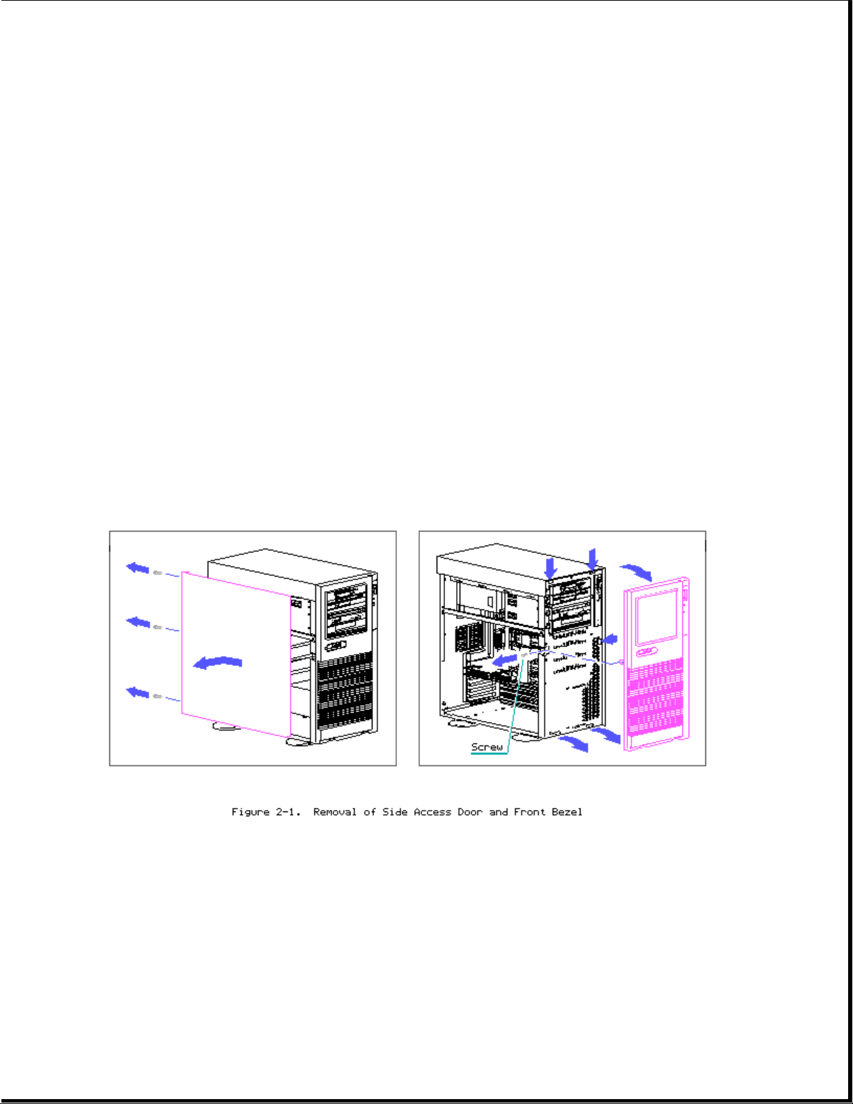
Side Access Door/Front Bezel
>>>>>>>>>>>>>>>>>>>>>>>>>>>>>>>>> WARNING <<<<<<<<<<<<<<<<<<<<<<<<<<<<<<<<<
High voltage present. Extreme care must be taken when running the COMPAQ
ProSignia PC Server without the system unit cover on.
>>>>>>>>>>>>>>>>>>>>>>>>>>>>>>>>>>>>><<<<<<<<<<<<<<<<<<<<<<<<<<<<<<<<<<<<<<
1. Loosen thumb screws (3) on back bezel.
2. Slide side access door back and then out.
3. Remove front bezel retaining screw (1).
4. Pull front bezel off at the three pressure points shown in figure.
System Unit Cover Removal
Page 7
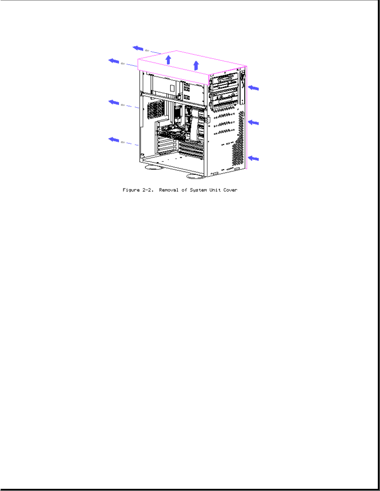
1. Remove side access door.
2. Unscrew Torx T-15 screws (4) at back panel.
3. Slide system unit cover backward and then up.
4. Reverse steps for replacing system unit cover.
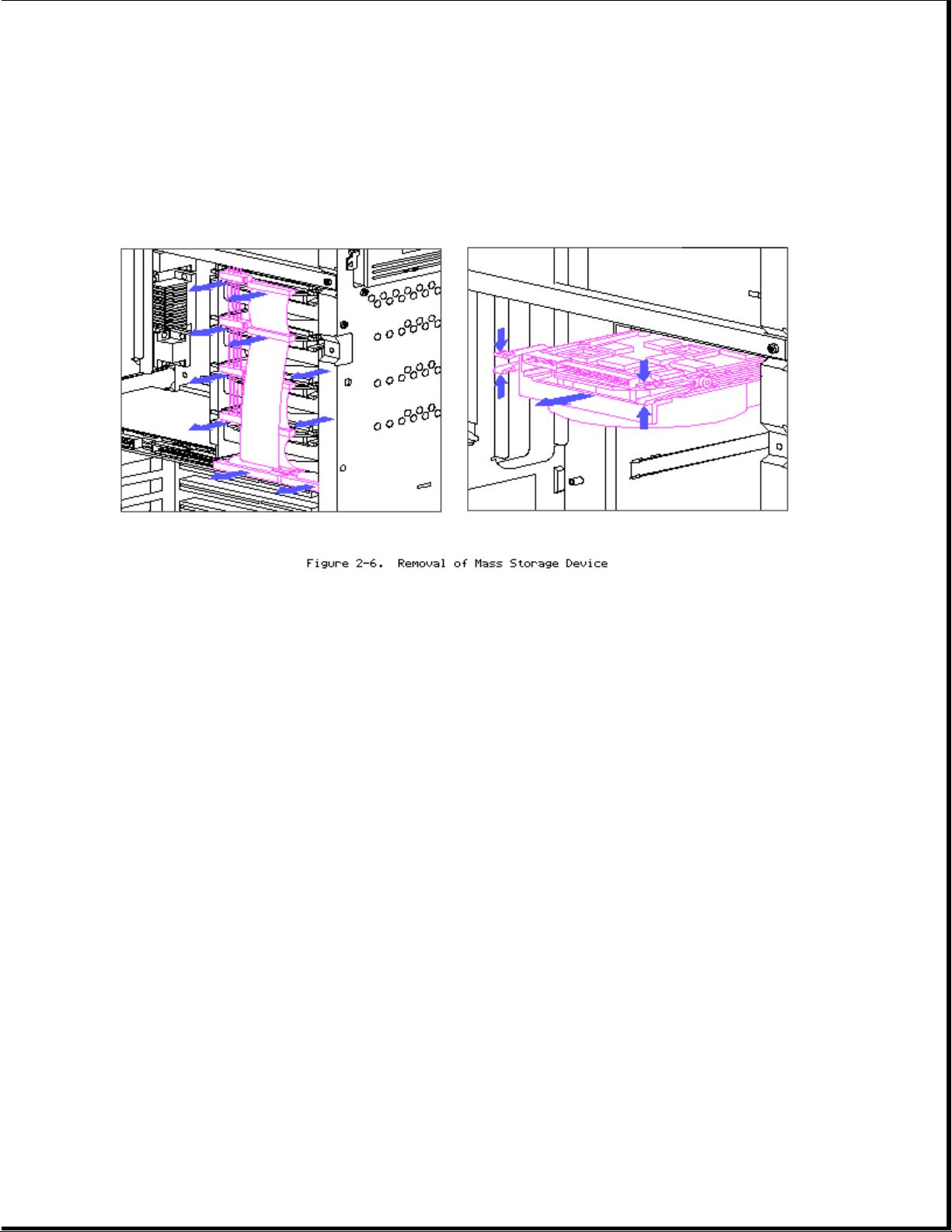
Mass Storage Devices
The COMPAQ ProSignia PC Server contains two areas for mass storage devices:
the removable media area and the side access drive bays.
Page 8
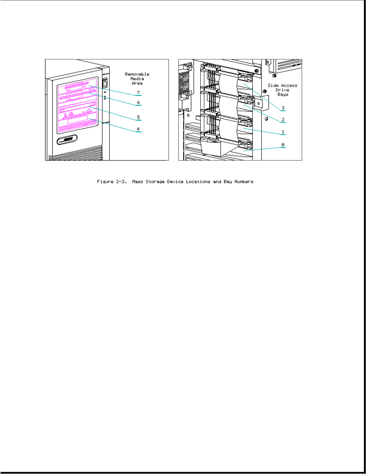
Removable Media Bays
Figure 2-3 shows the Removable Media Bays are located at the top of the
unit in the front panel. Table 2-1 shows the supported mass storage
devices and locations for the removable media bays.
Table 2-1. Removable Media Bay Configurations
===========================================================================
Mass Storage Device Storage Bays
7654
---------------------------------------------------------------------------
1.44-Megabyte Diskette Drive X X
1.2-Megabyte Diskette Drive X X
3.5-Inch Hard Drive X X X
525-Megabyte Tape Drive X X X
5.0-Gigabyte Digital Audio Tape (DAT) Drive X X X
===========================================================================
Page 9
1. Remove side access door and front bezel.
2. Disconnect power and signal cables from rear of drive.
3. Remove retaining screws (2).
4. Slide mass storage device out.
5. Reverse steps for installation.
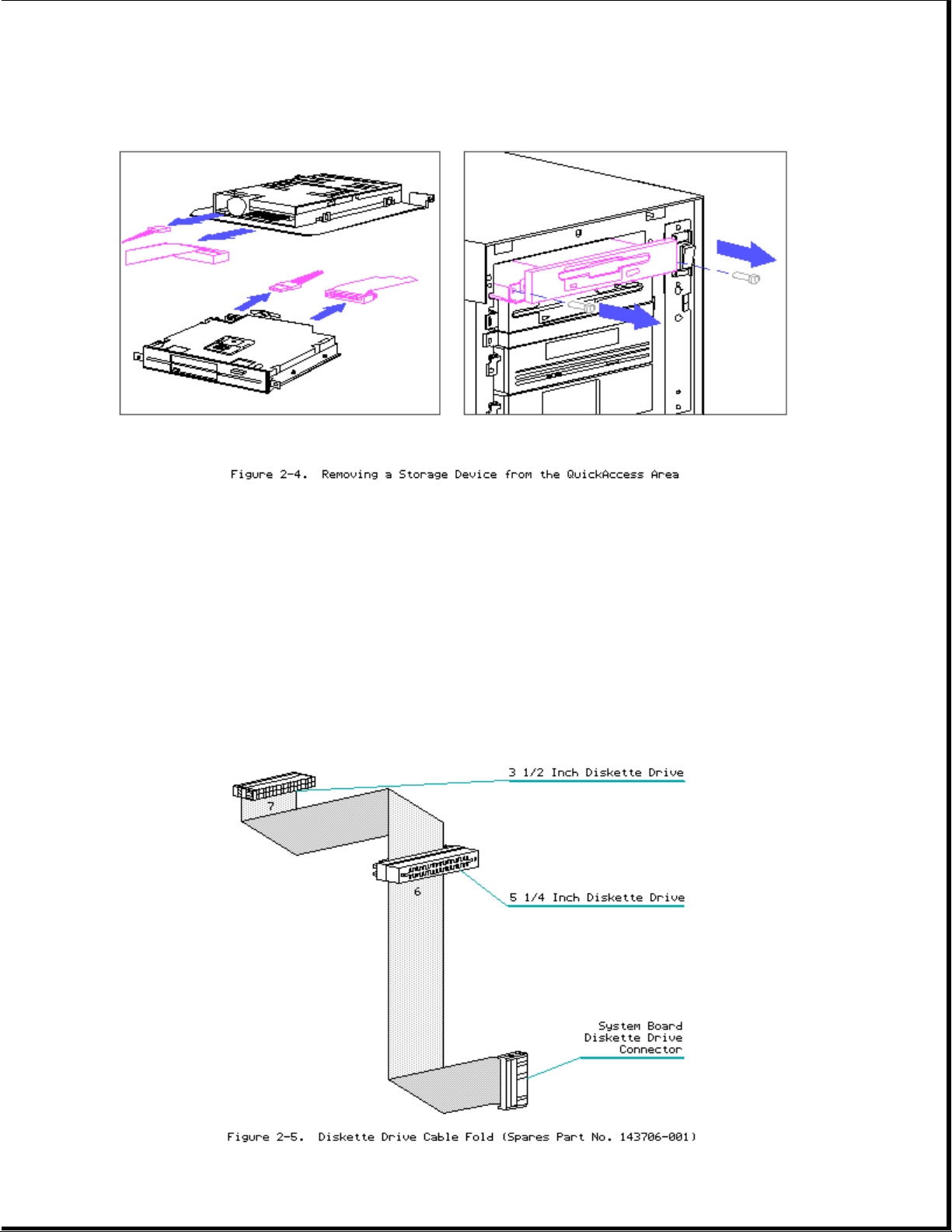
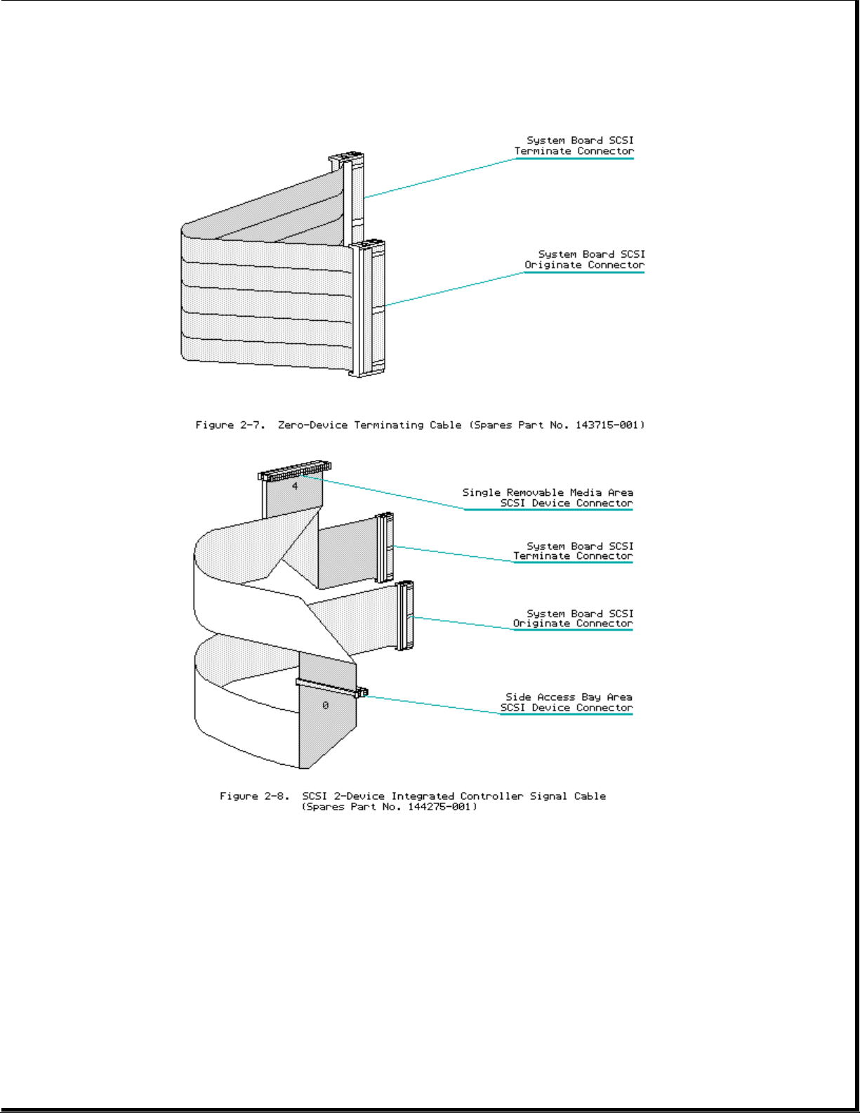
Cable Folding Diagrams for Removable Media Bays
Page 10
Side Access Drive Bays
The side access drive bay area is located behind the side access door and
can hold up to four half height snap-in hard drives.
1. Disconnect power and signal cables.
2. Remove hard drives by squeezing drive retaining clips and sliding
drives out.
3. Reverse order for installing drives.
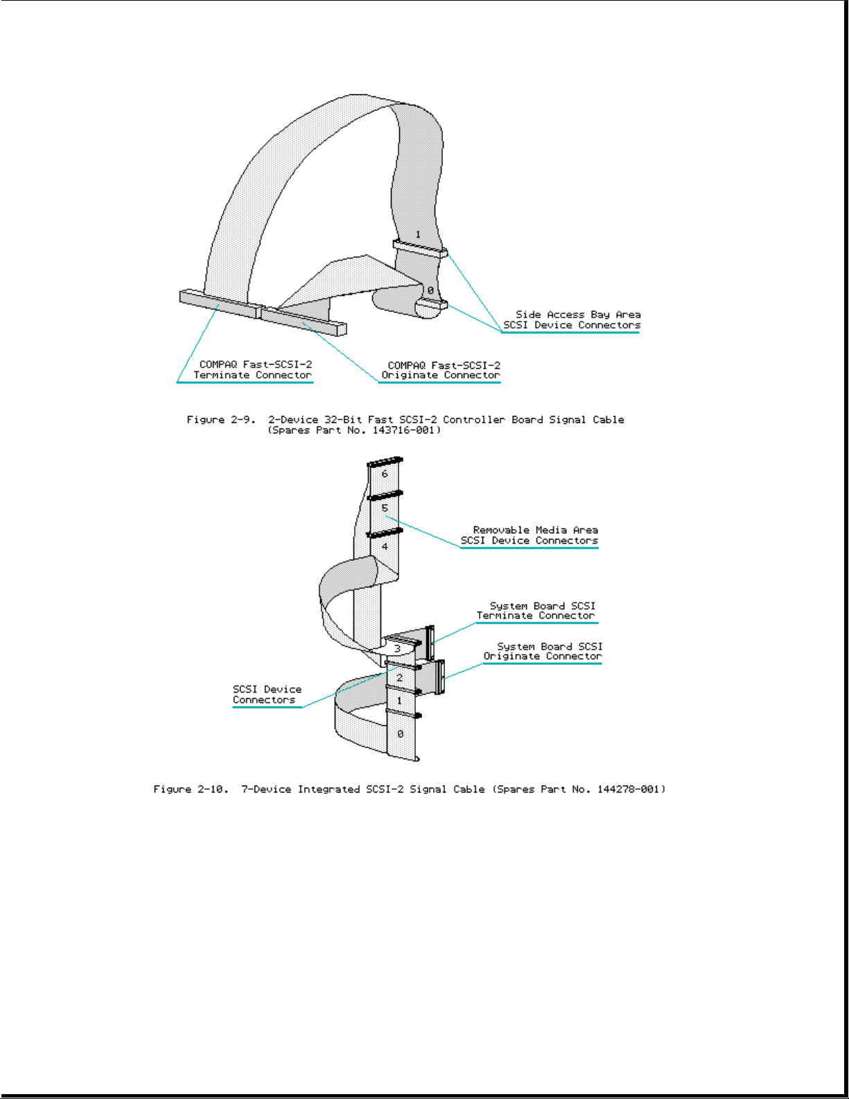
Cable Folding Diagrams for SCSI Devices and Side Access Drive Bays
Page 11
Page 12
Page 13
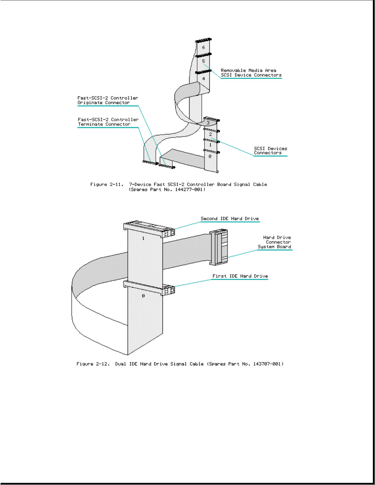
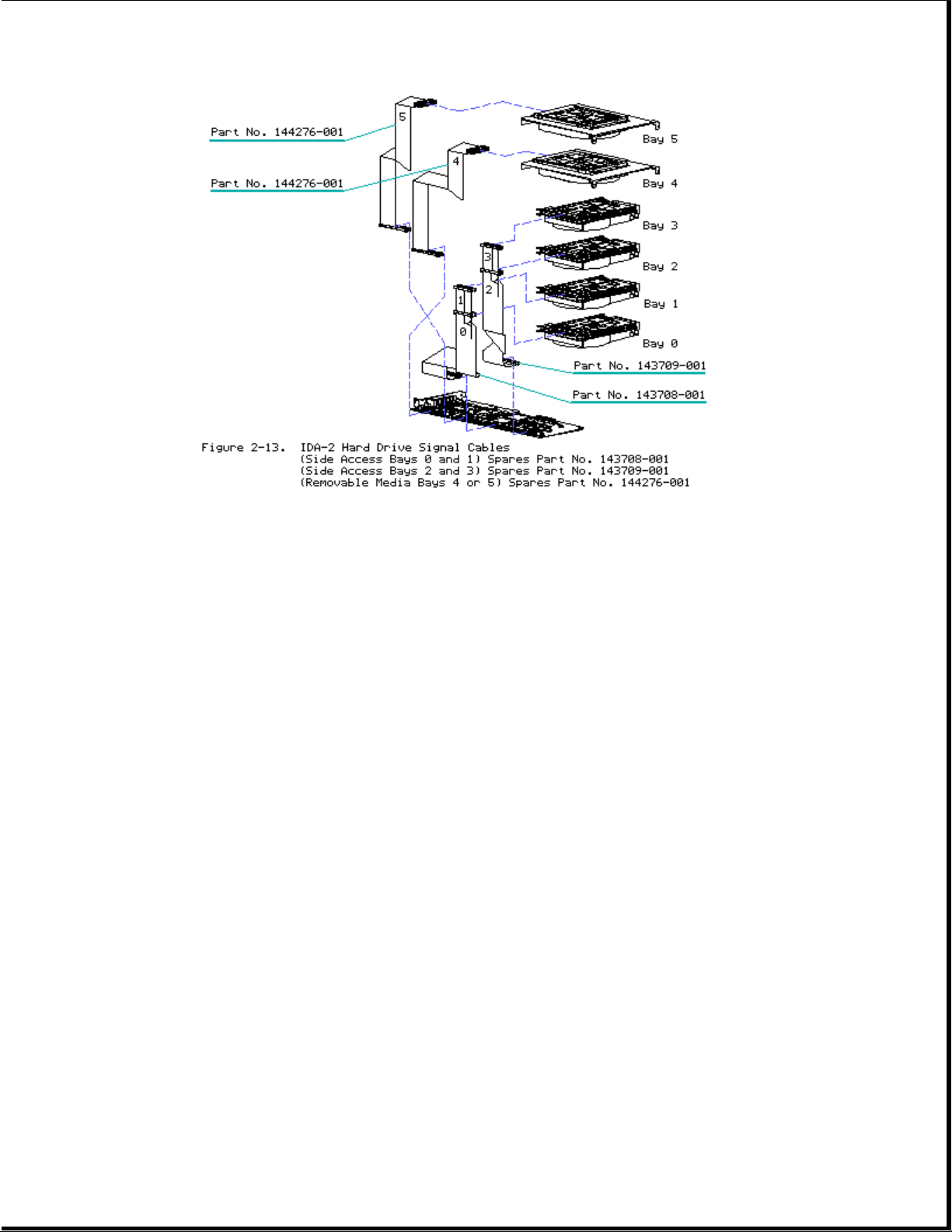
Cable Folding Diagrams for IDE Drives
Cable Folding Diagrams for IDA-2 Drives
Page 14
Boards
Memory
The COMPAQ ProSignia PC Server comes standard with either 4 or 8 megabytes
of system memory (depending on model). Memory can be expanded to a maximum
of 128 megabytes by installing any combination of 1-, 2-, 4-, 8-, 16-, or
32-Megabyte industry-standard SIMM modules in the four SIMM sockets on the
system board.
NOTE: The COMPAQ ProSignia supports a maximum of 128 MB of system RAM. The
standard 4 or 8 megabytes of system board memory will be ignored if
all 4 SIMM sockets have 32-MB SIMMs installed.
NOTE: COMPAQ only supports 16-MB SIMMS that use 16-megabit DRAM chips.
SIMM modules that use 4-megabit DRAM chips are not supported.
Page 15
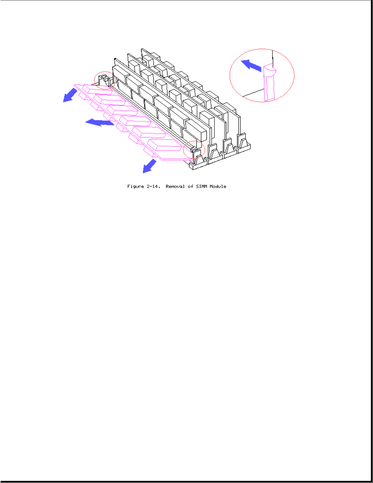
1. Remove all cables located near memory connectors.
2. Press SIMM connector latches outward.
3. Tilt SIMM module forward.
4. Lift SIMM module out.
5. To replace SIMM module reverse steps.
6. Run COMPAQ EISA Configuration utility if installed memory size has
changed.
Table 2-2 shows a sample of typical memory configurations for the COMPAQ
ProSignia PC Server.
Table 2-2. Example of SIMM Upgrade Combinations
===========================================================================
Total Memory Standard SIMM SIMM SIMM SIMM
System Socket 1 Socket 2 Socket 3 Socket 4
Memory
---------------------------------------------------------------------------
8 MB 4 MB 4-MB
12 MB 4 MB 4-MB 4-MB
16 MB 4 MB 8-MB 4-MB
24 MB 4 MB 16-MB 4-MB
36 MB 4 MB 32-MB
52 MB 4 MB 32-MB 16-MB
60 MB 4 MB 32-MB 16-MB 8-MB
68 MB 4 MB 32-MB 32-MB
76 MB 4 MB 32-MB 32-MB 8-MB
84 MB 4 MB 32-MB 32-MB 16-MB
92 MB 4 MB 32-MB 32-MB 16-MB 8-MB
100 MB 4 MB 32-MB 32-MB 32-MB
Page 16
116 MB 4 MB 32-MB 32-MB 32-MB 16-MB
128 MB 4 MB * 32-MB 32-MB 32-MB 32-MB
---------------------------------------------------------------------------
12 MB 8 MB 4-MB
16 MB 8 MB 8-MB
24 MB 8 MB 16-MB
36 MB 8 MB 16 MB 8-MB 4-MB
40 MB 8 MB 32-MB
56 MB 8 MB 32-MB 16-MB
64 MB 8 MB 32-MB 16-MB 8-MB
72 MB 8 MB 32-MB 32-MB
88 MB 8 MB 32-MB 32-MB 16-MB
104 MB 8 MB 32-MB 32-MB 32-MB
112 MB 8 MB 32-MB 32-MB 32-MB 8-MB
120 MB 8 MB 32-MB 32-MB 32-MB 16-MB
128 MB * 8 MB * 32-MB 32-MB 32-MB 32-MB
---------------------------------------------------------------------------
* The standard 4 or 8 megabytes of system board memory will be ignored if
all 4 SIMM sockets have 32-MB SIMMs installed.
===========================================================================
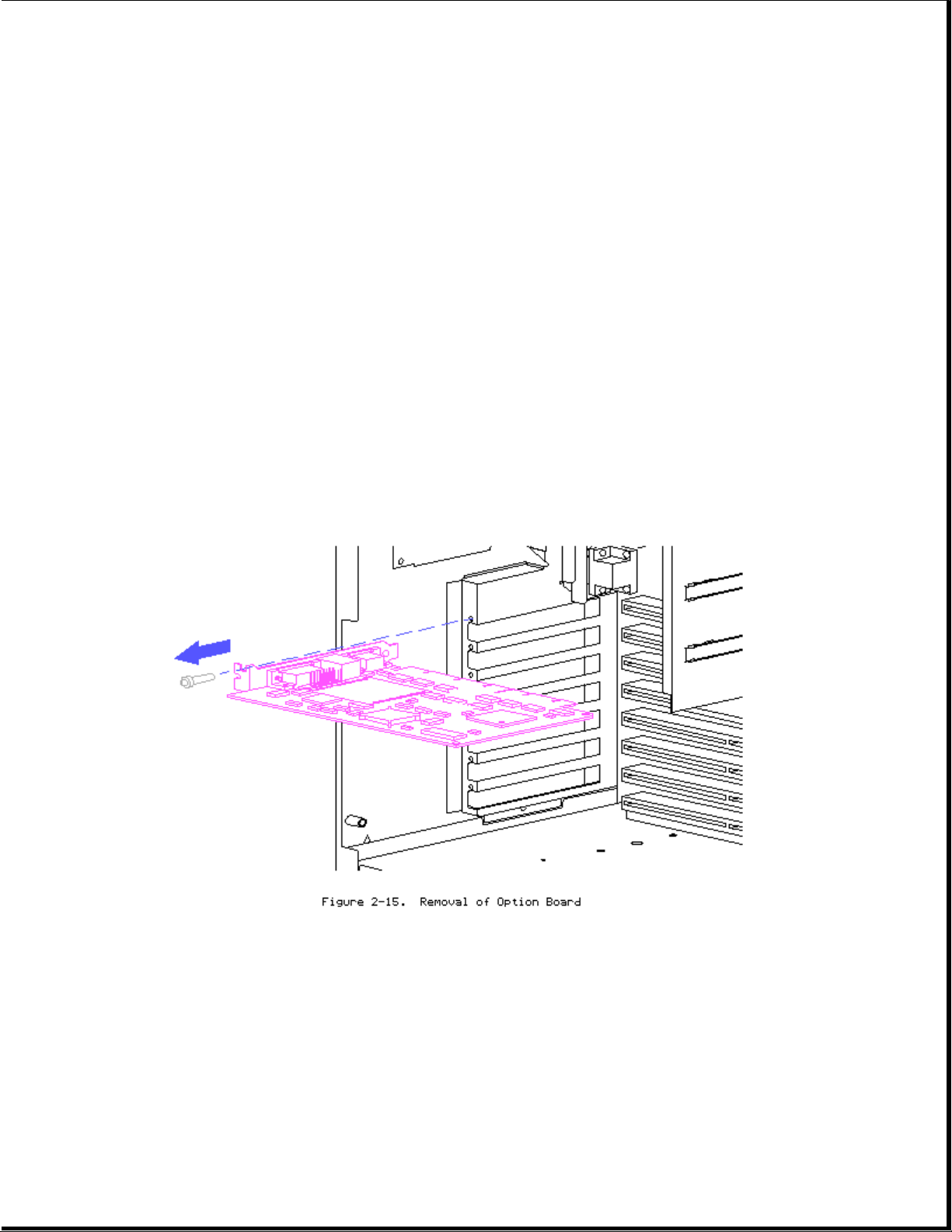
Option Boards
1. Remove any cables connected to board.
2. Remove retaining screw.
3. Pull board straight out.
System Board
Page 17
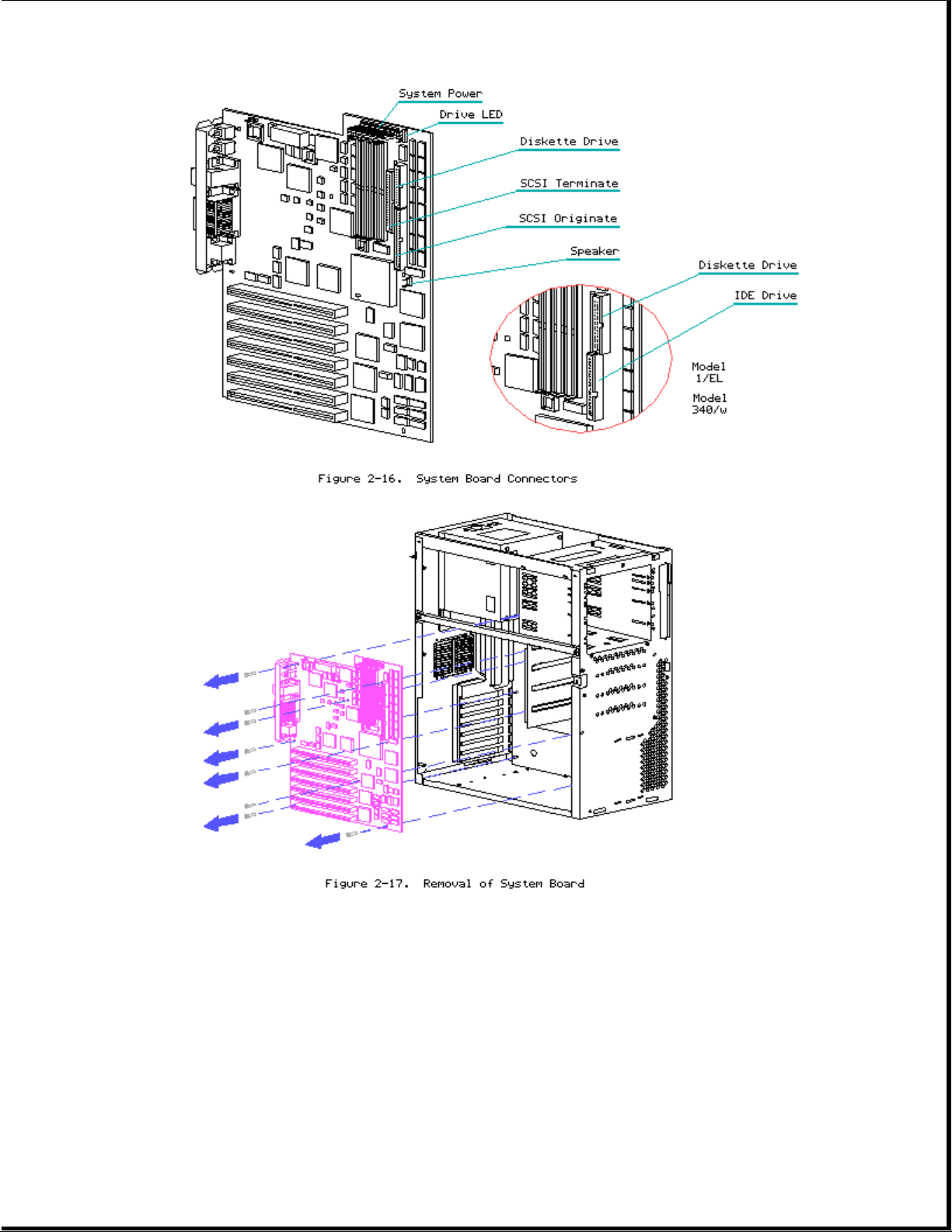
1. Remove all expansion boards.
2. Disconnect all cables from system board (Refer to Figure 2-16).
3. Remove retaining screws (8).
4. Lift board out being careful to avoid chassis and loose cables.
5. Reverse order to replace system board.
MISCELLANEOUS PARTS
Page 18
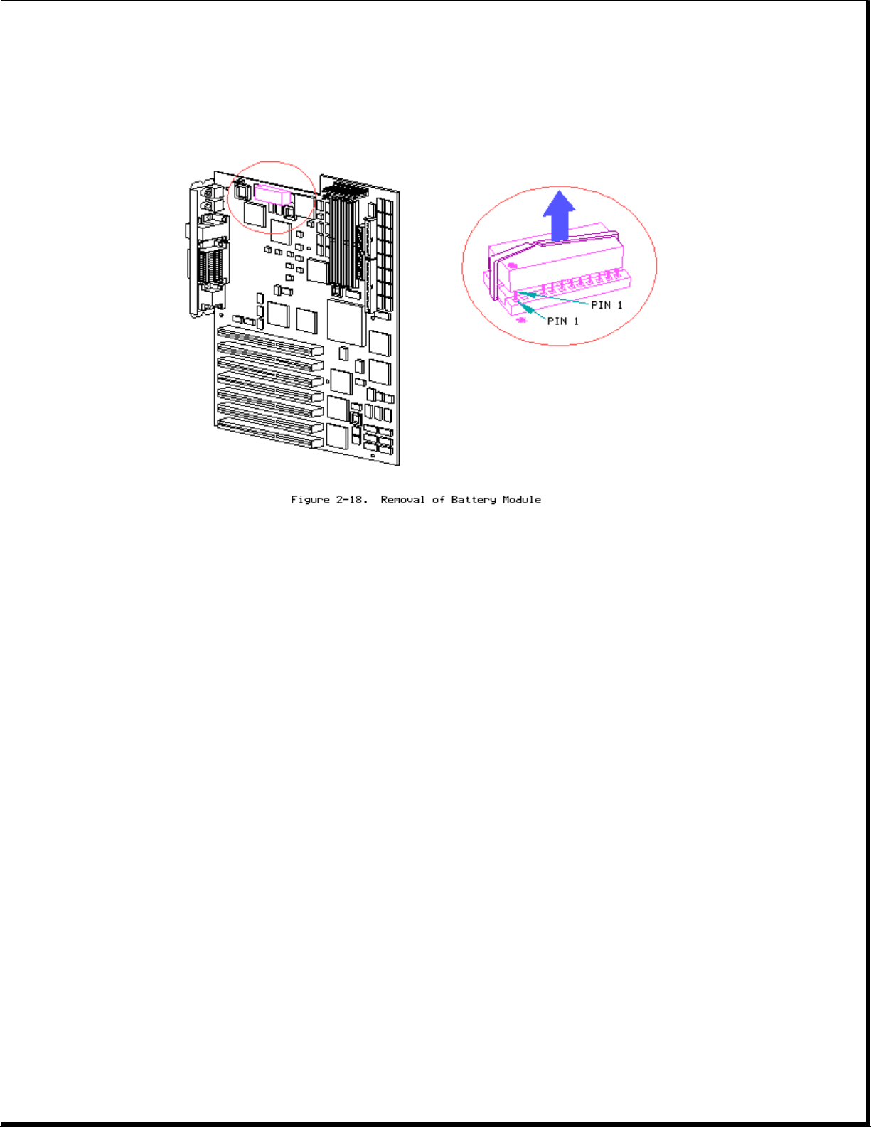
Battery/Clock Module
Removing the Battery/Clock Module
>>>>>>>>>>>>>>>>>>>>>>>>>>>>>>>>> WARNING <<<<<<<<<<<<<<<<<<<<<<<<<<<<<<<<<
The battery/clock module contains a lithium battery that may explode if
mishandled. Do not abuse, recharge, disassemble, or dispose of in fire or
heat above 90oC, incinerate, or expose to water or fire. Use only
replacement battery/clock modules supplied by Compaq Computer Corporation
(part no. 107872-001). Disposal of the battery/clock module should be
accomplished within compliance of local regulations or returned to Compaq
Computer Corporation by established parts return methods.
>>>>>>>>>>>>>>>>>>>>>>>>>>>>>>>>>>>>><<<<<<<<<<<<<<<<<<<<<<<<<<<<<<<<<<<<<<
NOTE: After replacing battery the COMPAQ EISA Configuration utility must be
run.
Power Supply
Page 19
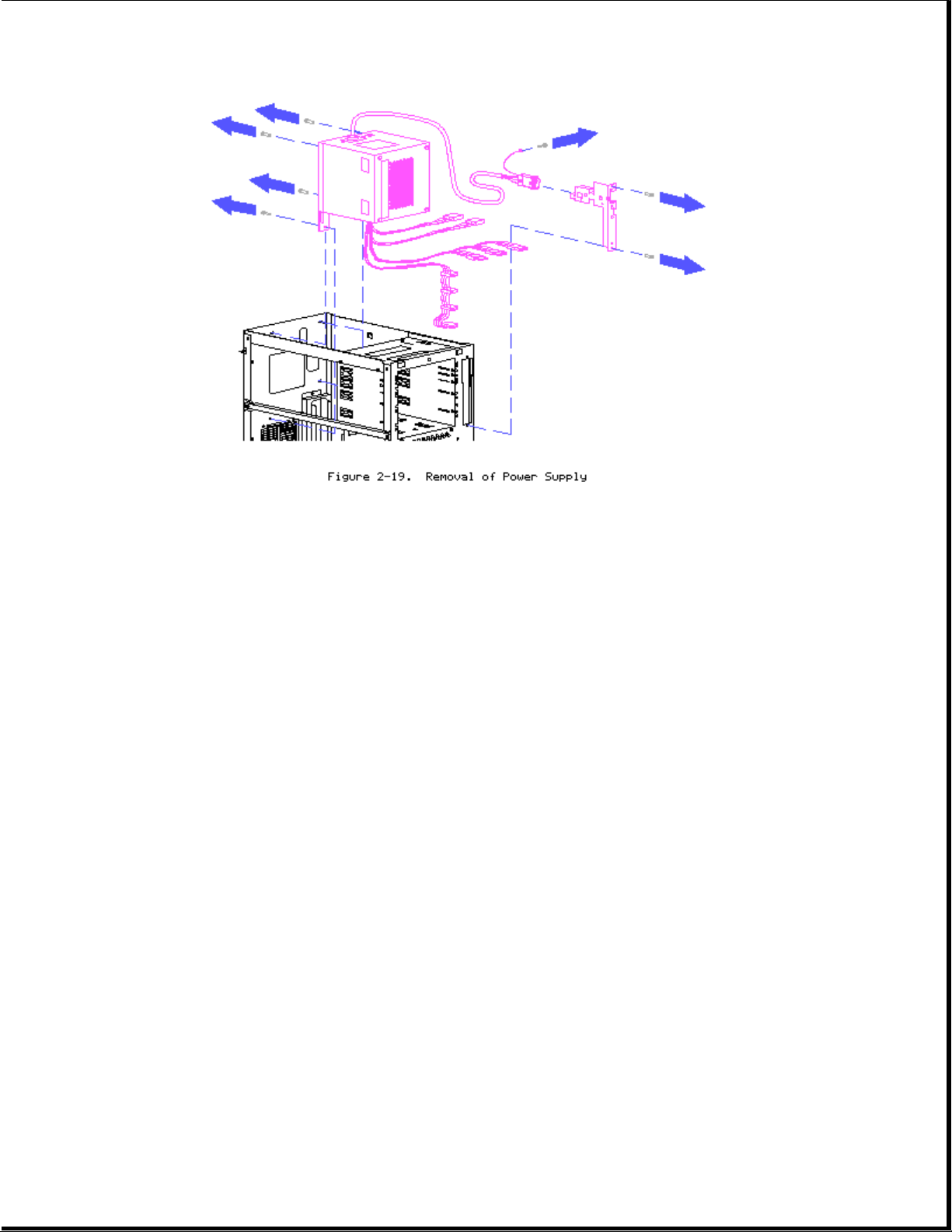
1. Turn power off and remove power cord from rear of unit.
2. Remove side access panel/front bezel/system unit cover.
3. Disconnect all power connectors from boards and or peripheral devices.
4. Remove front power switch bracket retaining screws (2).
5. Pull bracket out and remove power switch, grounding connector, and
cable from bracket.
6. Remove screws at rear of power supply (4).
7. Lift power supply out pulling switch and cable through chassis.
8. Reverse order for replacement.
NOTE: When replacing power supply, make sure that the power switch cable is
properly threaded through the bracket strain relief.
Page 20

Page 21

Chapter 3 Diagnostic Tools
This chapter describes software and firmware diagnostic tools available for
COMPAQ PC Server products. These include:
o Power-On Self-Test (POST)
o Diagnostics (DIAGS)
o Drive Array Advanced Diagnostics (DAAD)
o Automatic Server Recovery
o ROMPaq utility to upgrade flash ROMS
POWER-ON SELF-TEST (POST)
POST is a series of diagnostic tests that run automatically on COMPAQ
computers when the system is turned on. POST checks the following
assemblies to ensure that the computer system is functioning properly:
o Keyboard
o Power supply
o System board
o Memory
o Memory expansion boards
o Controllers
o Diskette drives
o Hard drives
If POST finds an error in the system, an error condition is indicated by an
audible and/or visual message. If an error code is displayed on the screen
during POST or after resetting the system, follow the instructions in
Table 3-1. The error messages and codes listed in Table 3-1 include all
codes generated by COMPAQ products. Your system will only generate those
codes which are applicable to your configuration and options.
Table 3-1. POST Error Messages
===========================================================================
Error Code Probable Source Action
of Problem
---------------------------------------------------------------------------
A Critical Error occurred A catastrophic system Run Diagnostics.
prior to this power-on error, which caused Replace failed assembly
the server to crash, as indicated.
has been logged.
---------------------------------------------------------------------------
A Correctable Memory Corrected Advanced ECC No action is required.
Error occurred prior to memory error has been Run Diagnostics and
the power-on logged. inspect the corrected
memory error. Probable
SIMM failure; replace
if required during
scheduled maintenance.
---------------------------------------------------------------------------
101-ROM Error System ROM checksum Run Diagnostics.
Replace failed assembly
as indicated or, contact
Page 22

your service provider.
---------------------------------------------------------------------------
101-I/O ROM Error Options ROM checksum Run Diagnostics.
Replace failed assembly
as indicated or, contact
your service provider.
---------------------------------------------------------------------------
102-System Board Failure DMA, timers, etc. Replace the system
board. Run the COMPAQ
EISA Configuration
Utility.
---------------------------------------------------------------------------
162-System Options Error No diskette drive or Run the EISA
mismatch in drive type Configuration Utility
and correct.
---------------------------------------------------------------------------
162-System Options Not Configuration Run the EISA
Set incorrect Configuration Utility
and correct.
---------------------------------------------------------------------------
163-Time & Date Not Set Invalid time or date Run the EISA
in configuration Configuration Utility
memory. and correct.
---------------------------------------------------------------------------
164-Memory Size Error Configuration memory Run the EISA
incorrect Configuration Utility
and correct.
---------------------------------------------------------------------------
170-EISA Expansion Device EISA Expansion board Check board for
Not Responding failure. secure installation.
Replace the failed
board if necessary.
---------------------------------------------------------------------------
Error Code Probable Source Action
of Problem
---------------------------------------------------------------------------
172-EISA Configuration Nonvolatile Run the EISA
Nonvolatile Memory configuration corrupt Configuration Utility
Invalid Initialization or jumper installed. and correct.
Aborted
---------------------------------------------------------------------------
173-EISA Slot ID Mismatch Board replaced, Run the EISA
configuration not Configuration Utility
updated. and correct.
---------------------------------------------------------------------------
174-EISA Configuration/ EISA board not found. Run the EISA
Slot Mismatch Device Not Configuration Utility
Found and correct.
---------------------------------------------------------------------------
175-EISA Configuration/ EISA board added, Run the EISA
Slot Mismatch Device configuration not Configuration Utility
Found updated. and correct.
---------------------------------------------------------------------------
176-Slot with Not EISA board in slot Run the EISA
Readable ID Yields Valid that should contain Configuration Utility
ID an ISA board. and correct.
---------------------------------------------------------------------------
177-Configuration Not Incomplete EISA Run the EISA
Complete Configuration. Configuration Utility
and correct.
Page 23

---------------------------------------------------------------------------
178-Processor Processor type or Run the EISA
Configuration Invalid step does not match Configuration Utility
configuration memory. and correct.
---------------------------------------------------------------------------
179-System Revision A board was installed Run the EISA
Mismatch which has a different Configuration Utility
revision date. and correct.
---------------------------------------------------------------------------
201-Memory Error RAM failure Run Diagnostics.
---------------------------------------------------------------------------
203-Memory Address Error RAM failure Run Diagnostics.
---------------------------------------------------------------------------
205-Processor Slot X Cache memory error. Replace the processor
Cache Memory Error board in the slot
indicated.
---------------------------------------------------------------------------
10 205-Memory Error Cache memory Run Diagnostics and
controller or RAM replace failed assembly.
failure
---------------------------------------------------------------------------
206-Processor Slot X Cache memory Replace the processor
Cache Controller Error controller or RAM board in the slot
failure. indicated.
---------------------------------------------------------------------------
Error Code Probable Source Action
of Problem
---------------------------------------------------------------------------
207-Invalid Memory Memory module Verify placement of
Configuration installed incorrectly. memory modules.
---------------------------------------------------------------------------
208-Invalid Memory Speed The speed of the The speed of the
`xxyy - memory is too slow, memory modules must be
where: xx00 = 60, 70 or 80 ns.
expansion board SIMMs Verify the speed of
are too slow, or 00yy the memory modules
= system board SIMMs installed and replace.
are too slow; xx and
yy have corresponding
bit set.
---------------------------------------------------------------------------
209-NCA RAM Error RAM failure Run Diagnostics and
replace failed
assembly.
---------------------------------------------------------------------------
212-Processor Slot X Processor in Slot X Replace the processor
System Processor Failed failure. in the slot indicated.
---------------------------------------------------------------------------
213-Processor Slot X- System processor Install processor in
System Processor Not configured for slot the slot indicated or
Installed indicated is missing. run the EISA
Configuration Utility
to remove the processor
from the .CFG file.
---------------------------------------------------------------------------
301-Keyboard Error Keyboard failure. Turn off the computer,
then reconnect the
keyboard.
---------------------------------------------------------------------------
301-Keyboard Error or Keyboard failure. Replace the keyboard.
Page 24

Test Fixture Installed
---------------------------------------------------------------------------
ZZ-301-Keyboard Error Keyboard failure. 1. A key is stuck.
(ZZ represents the Try to free it.
Keyboard Scan Code.) 2. Replace the
keyboard.
---------------------------------------------------------------------------
303-Keyboard Controller System board, Check with your
Error keyboard, or mouse Authorized COMPAQ
controller failure. Reseller.
---------------------------------------------------------------------------
304-Keyboard or System Keyboard, keyboard 1. Make sure the
Unit Error cable, or system board keyboard is
failure. attached.
2. Run Diagnostics to
determine which is
in error.
3. Replace the part
indicated.
--------------------------------------------------------------------------40X-Parallel Port X Both external and Run the EISA
Address Assignment internal ports are Configuration Utility.
Conflict assigned to parallel
port X
--------------------------------------------------------------------------Error Code Probable Source Action
of Problem
--------------------------------------------------------------------------402-Monochrome Adapter Monochrome display Replace the monochrome
Failure controller. display controller.
--------------------------------------------------------------------------501-Display Adapter Video display Replace the video board.
Failure controller.
--------------------------------------------------------------------------601-Diskette Controller Diskette controller 1. Make sure the
Error circuitry failure. diskette drive
cables are attached.
2. Replace the diskette
drive and/or cable.
3. Replace the system
board.
--------------------------------------------------------------------------602-Diskette Boot Diskette in drive A Replace the diskette.
not bootable.
--------------------------------------------------------------------------605-Diskette Drive Type Mismatch in drive Run the EISA
Error type. Configuration Utility to
set diskette type
correctly.
--------------------------------------------------------------------------607-No Response Received Configuration error. Run the EISA
at Primary Address From Configuration Utility.
External Floppy
Controller. Internal
Floppy Controller Has
Enabled.
--------------------------------------------------------------------------611-Primary Floppy Port Configuration error. Run the EISA
Address Assignment Configuration Utility
Conflict and correct.
Page 25

--------------------------------------------------------------------------612-Secondary Floppy Configuration error. Run the EISA
Port Address Assignment Configuration Utility
Conflict and correct.
--------------------------------------------------------------------------702-A coprocessor has Installed coprocessor Run the EISA
been detected that was not configured. Configuration Utility
not reported by CMOS. and correct.
--------------------------------------------------------------------------703-CMOS Reports A Coprocessor or 1. Run the EISA
Coprocessor That Has configuration error. Configuration
Not Been Detected By Utility and correct.
POST 2. Replace the
coprocessor.
--------------------------------------------------------------------------1151-COM Port 1 Both external and Run the EISA
internal serial ports Configuration Utility
are assigned to COM1. and correct.
--------------------------------------------------------------------------1152-COM Port 2 Both external and Run the EISA
internal serial ports Configuration Utility
are assigned to COM2. and correct.
--------------------------------------------------------------------------Error Code Probable Source Action
of Problem
--------------------------------------------------------------------------1153-COM Port 3 Both external and Run the EISA
internal serial ports Configuration Utility
are assigned to COM3. and correct.
--------------------------------------------------------------------------1154-COM Port 4 Both external and Run the EISA
internal serial ports Configuration Utility
are assigned to COM4. and correct.
--------------------------------------------------------------------------1701-SCSI Controller A test on the Run Diagnostics.
Failure Controller failed. Replace failed assembly
as indicated or, contact
your service provider.
--------------------------------------------------------------------------1771-Primary Disk Port Internal and external Run the EISA
Address Assignment hard drive controllers Configuration Utility
Conflict are both assigned to and correct.
the primary address.
--------------------------------------------------------------------------1772-Secondary Disk Port Address Assignment Run the EISA
Conflict. Internal Configuration Utility
and external hard and correct.
drive controllers are
both assigned to the
secondary address.
--------------------------------------------------------------------------1777-Slot # Drive Array Configuration error. Run the EISA
Controller has been Configuration Utility
upgraded. Run System and correct.
Configuration Utility
--------------------------------------------------------------------------1778-Slot # Drive Array This message appears No action necessary.
resuming Automatic Data whenever a controller
Recovery process reset or power cycle
occurs while Automatic
Page 26

Data Recovery is in
progress.
--------------------------------------------------------------------------1779-Slot # Drive Array Intermittent drive If this message
Replacement drive(s) failure and/or appears and drive X
detected OR previously possible loss of has not been replaced,
failed drive now appears data. this indicates an
to be operational: Drive intermittent drive
X. Restore data from failure. This message
backup if replacement also appears once
drive has been installed. immediately following
drive replacement
whenever data must be
restored from backup.
--------------------------------------------------------------------------1780-Disk 0 Failure Hard drive/format Run Diagnostics.
error. Replace failed assembly
as indicated or, contact
your service provider.
--------------------------------------------------------------------------Error Code Probable Source Action
of Problem
--------------------------------------------------------------------------1781-Disk 1 Failure Hard drive/format Run Diagnostics.
error. Replace failed assembly
as indicated or, contact
your service provider.
--------------------------------------------------------------------------1782-Disk Controller Hard disk drive Run Diagnostics.
circuitry error. Replace failed assembly
as indicated or, contact
your service provider.
--------------------------------------------------------------------------1783-Slot # Drive Array Drive Array If message appears
Controller Failure Controller is following a ROM
defective or not installation, ROM is
installed properly. defective or not
installed properly.
Otherwise, replace the
IDA-2.
--------------------------------------------------------------------------1784-Slot # Drive Array Defective drive Check for loose cables.
Drive Failure, Physical and/or cables. Replace defective drive
drive replacement X and/or cable(s).
needed: Drive X
--------------------------------------------------------------------------1785-Slot # Drive Array Configuration error. Run the EISA
Not Configured Configuration Utility
and correct.
--------------------------------------------------------------------------1786-Drive Array Interim Data Recovery Press F1 key to allow
Recovery Needed mode. Data has not Automatic Data Recovery
The following drive(s) been recovered yet. to begin. Data will
need Automatic Data automatically be
Recovery: Drive X. restored to drive X
Select "F1" to continue now that the drive has
with recovery of data been replaced or now
to drive(s). Select "F2" seems to be working.
to continue without -Orrecovery of data to Press the F2 key and the
Page 27

drive(s). system will continue to
operate in the Interim
Data Recovery mode.
--------------------------------------------------------------------------1787-Slot # Drive Array Hard drive X failed 1. Replace drive X as
Operating in Interim or cable is loose or soon as possible.
Recovery Mode. defective. Following 2. Check loose cables.
Physical drive a system restart, this 3. Replace defective
replacement needed: message reminds you cables.
Drive X that drive X is
defective and fault
tolerance is being
used.
--------------------------------------------------------------------------Error Code Probable Source Action
of Problem
--------------------------------------------------------------------------1788-Slot # Drive Drives are not Reinstall the drives
Array Reports Incorrect installed in their correctly as indicated.
Drive Replacement original positions, Press F1 to restart
Drive(s) should have so the drives have the computer with the
been replaced: Drive X been disabled. See drive array disabled.
Drive(s) were note below. -Orincorrectly replaced: Press F2 to use the
Drive Y Select "F1" to drives as configured
continue - drive array and lose all the
will remain disabled. data on them.
Select "F2" to reset
configuration - all
data will be lost.
NOTE: The 1788 error message might also be displayed inadvertently due to a
bad power cable connection to the drive or by noise on the data
cable. If this message was due to a bad power cable connection, but
not due to an incorrect drive replacement, repair the connection and
press F2. Or; If this message was not due to a bad power cable
connection, and no drive replacement took place, this could indicate
noise on the data cable. Check cable for proper routing.
--------------------------------------------------------------------------1789-Slot # Drive Array Cable or hard drive 1. Check the cable
Physical Drive(s) Not failure. connections.
Responding. 2. If cables are
Check cables or replace connected, replace
physical drive X. the drive.
Select "F1" to continue 3. If you do not
- drive array will want to replace the
remain disabled. drives now, press
Select "F2" to fail F2.
drive(s) that are not
responding - Interim
Recovery Mode will be
enabled if configured
for fault tolerance.
--------------------------------------------------------------------------1790-Disk 0 Error Hard drive error or Run the EISA
wrong drive type. Configuration Utility
and Diagnostics and
correct.
--------------------------------------------------------------------------1791-Disk 1 Error Hard drive error or Run the EISA
Page 28

wrong drive type. Configuration Utility
and Diagnostics and
correct.
--------------------------------------------------------------------------Error Code Probable Source Action
of Problem
--------------------------------------------------------------------------1792-Slot # Drive Array This indicates that No action necessary;
- Valid Data Found in while the system was no data has been lost.
Array Accelerator. Data in use, power was Perform orderly system
will automatically be interrupted while system shut-downs to
written to drive array. data was in the Array avoid data remaining
Accelerator memory. in the Array
Power was then Accelerator.
restored within eight
to ten days, and the
data in the Array
Accelerator was
flushed to the drive
array.
--------------------------------------------------------------------------1793-Slot # Drive Array This indicates that Power was not restored
- Array Accelerator while the system was within eight to ten
Battery Depleted. Data in use, power was days. Perform orderly
in Array Accelerator has interrupted while system shut-downs to
been lost. (Error data was in the avoid data remaining in
message 1794 also Array Accelerator the Array Accelerator.
displays.) memory. Array
Accelerator batteries
failed. Data in Array
Accelerator has been
lost.
--------------------------------------------------------------------------1794-Slot # Drive Array This is a warning Replace the Array
Accelerator Battery that the battery Accelerator board if
Charge Low. charge is below 75%. batteries do not
Array Accelerator is Posted writes are recharge within 36
temporarily disabled. disabled. power-on hours.
Array Accelerator will
be reenabled when
battery reaches full
charge.
--------------------------------------------------------------------------1795-Slot # Drive Array This indicates that 1. Match the Array
- Array Accelerator while the system was Accelerator to the
Configuration Error. in use, power was correct drive array.
Data does not correspond interrupted while -Orto this drive array. data was in the Array 2. Run the EISA
Array Accelerator is Accelerator memory. Configuration
temporarily disabled. The data stored in the Utility to clear the
Array Accelerator does data in the Array
not correspond to this Accelerator.
drive array.
--------------------------------------------------------------------------1796-Slot # Drive Array Array Accelerator is 1. Check that the
- Array Accelerator is defective or has been Array Accelerator is
Not Responding. removed. properly seated.
Array Accelerator is 2. Run the EISA
temporarily disabled. Configuration
Utility to
Page 29

reconfigure the
COMPAQ IDA-2
without the Array
Accelerator.
--------------------------------------------------------------------------Error Code Probable Source Action
of Problem
--------------------------------------------------------------------------1797-Slot # Drive Array Hard parity error Array Accelerator is
- Array Accelerator Read while reading data disabled.
Error Occurred. Data from posted writes
in Array Accelerator memory.
has been lost. Array
Accelerator is disabled.
--------------------------------------------------------------------------1798-Slot # Drive Array Hard parity error Array Accelerator
- Array Accelerator while writing data to is disabled.
Write Error Occurred. posted writes memory.
Array Accelerator is
disabled.
--------------------------------------------------------------------------1799-Slot # Drive Array Volume failed due to Press F1 to continue
- Drive(s) Disabled due loss of data in with logical drives
to Array Accelerator posted-writes memory. disabled or F2 to
Data Loss. Select "F1" accept data loss and
to continue with logical reenable logical
drives disabled. Select drive.
"F2" to accept data loss
and to reenable logical
drives.
--------------------------------------------------------------------------Fixed Disk Parameter Extended BIOS data Contact your service
Table or BIOS Error. area being corrupted provider.
System Halted.
--------------------------------------------------------------------------IOCHECK Active, Slot X Defective board in Run Diagnostics.
slot X Replace failed assembly
as indicated.
--------------------------------------------------------------------------Bus Master Time-out Defective board in Run Diagnostics.
Slot X slot X Replace failed assembly
as indicated.
--------------------------------------------------------------------------Parity Check 2-System A RAM parity error Run Diagnostics.
Board Memory. occurred. Replace failed assembly
Parity Check 2-SIMM as indicated.
Memory Modules B, C, D, E
--------------------------------------------------------------------------(Run System Configuration A configuration error Press F10 to run EISA
Utility = "F10" key) occurred during POST. Configuration Utility.
--------------------------------------------------------------------------1600-32-Bit Server Server Manager/R board Run Diagnostics.
Manager/R Board Failure failure. Error code Replace failed assembly
displays after error as indicated or contact
message. your service provider.
--------------------------------------------------------------------------(RESUME = "F1" KEY) As indicated to Press the F1 key.
continue.
===========================================================================
Page 30

DIAGNOSTICS (DIAGS)
Diagnostic error codes occur if the system recognizes a problem while
running the Diagnostics program. These error codes help identify possible
defective subassemblies.
Tables 3-2 through 3-17 list possible error codes, a description of the
error condition, and the action required to resolve the error condition.
In each case, the Recommended Action column lists the steps necessary to
correct the problem. After completing each step, run the Diagnostics
program to verify whether the error condition has been corrected. If the
error code reappears, perform the next step, then run the Diagnostics
program again. Follow this procedure until the Diagnostics program no
longer detects an error condition.
For assistance in the removal and replacement of a particular subassembly,
see Chapter 2, "Removal and Replacement Procedures."
If you encounter an error condition, complete the following steps before
starting problem isolation procedures:
1. Ensure that there is proper ventilation. The computer should have
approximately 3 inches (7 to 8 cm) clearance at the front and back of
the system unit.
2. Turn off the computer and peripheral devices.
3. Disconnect any peripheral devices other than the monitor and keyboard.
Do not disconnect the printer if you want to test it or use it to log
error messages.
4. Delete the power-on password, if set. You will know that the power-on
password is set when a key icon appears on the screen when POST
completes. If this occurs, you must enter the password to continue.
To delete the password, type the current password and press the Enter
key.
5. If you do not have access to the password, you must disable the
power-on password by using the Password Disable switch on the system
board.
6. Install an Ethernet loopback plug when instructed to by Diagnostics
utility. (part no. 142054-001)
7. Run the latest version of Diagnostics.
Table 3-2. Primary Processor Test Error Codes
===========================================================================
Error Description Recommended Action
Code
---------------------------------------------------------------------------
101-xx CPU test failed Replace the processor board and retest.
---------------------------------------------------------------------------
103-xx DMA page registers test Replace the processor board and retest
failed for error codes 103-xx through 106-xx.
104-xx Interrupt controller
Page 31

master test failed
105-xx Port 61 error
106-xx Keyboard controller
self-test failed
---------------------------------------------------------------------------
107-xx CMOS RAM test failed The following steps apply to error
codes 107-xx through 109-xx.
108-xx CMOS interrupt test 1. Replace the battery/clock module
failed and retest.
2. Replace the system board and
109-xx CMOS clock load data test retest.
failed
---------------------------------------------------------------------------
110-xx Programmable timer load Replace the system board and retest
data test failed for error codes 110-xx through 113-xx.
111-xx Refresh detect test
failed
112-xx Speed test slow mode out
of range
113-xx Protected mode test
failed.
---------------------------------------------------------------------------
114-xx Speaker test failed The following steps apply to 114-xx
error codes:
1. Verify the speaker connection.
2. Replace the speaker and retest.
3. Replace the system board and
retest.
--------------------------------------------------------------------------116-xx Cache test failed Replace the system board and retest.
--------------------------------------------------------------------------199-xx Installed devices test The following steps apply to 199-xx
failed error codes:
1. Check the system configuration.
2. Verify cable connections.
3. Check switch and/or jumper
settings.
4. Run the Configuration utility.
5. Replace the processor board and
retest.
6. Replace the system board and
retest.
===========================================================================
Table 3-3. Memory Test Error Codes
===========================================================================
Error Description Recommended Action
Code
--------------------------------------------------------------------------200-xx Invalid memory Reinsert memory modules in correct
configuration location.
--------------------------------------------------------------------------201-xx Memory machine ID test The following steps apply to error
Page 32

failed codes 201-xx and 202-xx:
1. Replace the system ROM and retest.
202-xx Memory system ROM 2. Replace the processor board and
checksum failed retest.
3. Replace the memory expansion board
and retest.
--------------------------------------------------------------------------203-xx Memory write/read test The following steps apply to error
failed codes 203-xx through 210-xx:
1. Replace the memory module and
204-xx Memory address test retest.
failed 2. Replace the processor board and
retest.
205-xx Walking I/O test failed 3. Replace the memory expansion board
and retest.
206-xx Increment pattern test
failed
210-xx Random pattern test
failed
===========================================================================
Table 3-4. Keyboard Test Error Codes
===========================================================================
Error Description Recommended Action
Code
--------------------------------------------------------------------------301-xx Keyboard short test, 8042 The following steps apply to error
self-test failed codes 301-xx through 304-xx:
1. Check the keyboard connection.
302-xx Keyboard long test failed If disconnected, turn off the
computer and connect the keyboard.
303-xx Keyboard LED test, 8042 2. Replace the keyboard and retest.
self-test failed 3. Replace the system board and
retest.
304-xx Keyboard typematic test
failed.
===========================================================================
Table 3-5. Parallel Printer Test Error Codes
===========================================================================
Error Description Recommended Action
Code
--------------------------------------------------------------------------401-xx Printer failed or not The following steps apply to error
connected codes 401-xx through 498-xx:
1. Connect the printer.
402-xx Printer data register 2. Check the power to the printer.
failed 3. Install the loopback connector
and retest.
403-xx Printer pattern 4. Check the switch on the
test failed Serial/Parallel Interface board
(if applicable).
498-xx Printer failed or not 5. Replace the Serial/Parallel
connected Interface board (if applicable).
6. Replace the system board and
retest.
===========================================================================
Table 3-6. Video Display Unit Test Error Codes
Page 33

===========================================================================
Error Description Recommended Action
Code
--------------------------------------------------------------------------501-xx Video controller test The following steps apply to error
failed codes 501-xx through 516-xx:
1. Replace the monitor and retest.
502-xx Video memory test failed 2. Replace the Advanced VGA board
and retest.
503-xx Video attribute test 3. Replace the system board and
failed retest.
504-xx Video character set test
failed
505-xx Video 80 x 25 mode
9 x 14-character cell
test failed
506-xx Video 80 X 25 mode
8 X 8-character cell
test failed
507-xx Video 40 X 25 mode test
failed
508-xx Video 320 X 200 mode color
set 0 test failed
509-xx Video 320 X 200 mode color
set 1 test failed
510-xx Video 640 x 200 mode test
failed
511-xx Video screen memory page
test failed
512-xx Video gray scale test
failed
514-xx Video white screen test
failed
516-xx Video noise pattern test
failed
===========================================================================
Table 3-7. Diskette Drive Error Test Codes
===========================================================================
Error Description Recommended Action
Code
--------------------------------------------------------------------------600-xx Diskette ID drive types The following steps apply to error
test failed codes 600-xx through 698-xx:
1. Replace the diskette and retest.
601-xx Diskette format failed 2. Check and/or replace the diskette
power and signal cables and retest.
602-xx Diskette read test failed 3. Replace the diskette drive and
retest.
Page 34

603-xx Diskette write/read/ 4. Replace the system board and
compute test failed retest.
604-xx Diskette random seek test
failed
605-xx Diskette ID media failed
606-xx Diskette speed test
failed
607-xx Diskette wrap test failed
608-xx Diskette write protect
test failed
609-xx Diskette reset controller
test failed
610-xx Diskette change line test
failed
694-xx Pin 34 is not cut on
360-KB diskette drive
697-xx Diskette type error
698-xx Diskette drive speed not
within limits
--------------------------------------------------------------------------699-xx Diskette drive/media ID The following steps apply to 699-xx
error error codes:
1. Replace the media.
2. Run the Configuration utility.
===========================================================================
Table 3-8. Monochrome Video Board Test Error Codes
===========================================================================
Error Description Recommended Action
Code
--------------------------------------------------------------------------802-xx Video memory test failed The following steps apply to error
codes 802-xx and 824-xx:
824-xx Monochrome video text 1. Replace monitor and retest.
mode test failed 2. Replace the Advanced VGA board and
retest.
3. Replace monochrome board and
retest.
4. Replace the system board and
retest.
===========================================================================
Table 3-9. Serial Test Error Codes
===========================================================================
Page 35

Error Description Recommended Action
Code
--------------------------------------------------------------------------1101-xx Serial port test failed The following steps apply to error
codes 1101-xx through 1109-xx:
1109-xx Clock register test 1. Check the switch settings on the
failed Serial/Parallel Interface board
(if applicable).
2. Replace the Serial/Parallel
Interface board (if applicable).
3. Replace the system board and
retest.
===========================================================================
Table 3-10. Modem Communications Test Error Codes
===========================================================================
Error Description Recommended Action
Code
--------------------------------------------------------------------------1201-xx Modem internal loopback The following steps apply to error
test failed codes 1201-xx through 1210-xx:
1. Refer to the modem documentation
1202-xx Modem time-out test for correct setup procedures.
failed 2. Check the modem line.
3. Replace the modem and retest.
1203-xx Modem external termination
test failed
1204-xx Modem auto originate test
failed
1206-xx Dial multifrequency tone
test failed
1210-xx Modem direct connect test
failed
===========================================================================
Table 3-11. Fixed Disk Drive Test Error Codes
===========================================================================
Error Description Recommended Action
Code
--------------------------------------------------------------------------1700-xx Fixed disk ID drive The following steps apply to error
types test failed codes 1700-xx through 1799-xx:
1. Run the Configuration Utility
1701-xx Fixed disk format test and verify the drive type.
failed 2. Replace the fixed disk drive
signal and power cables and
1702-xx Fixed disk read test retest.
failed 3. Replace the fixed drive
controller and retest.
1703-xx Fixed disk write/read/ 4. Replace the fixed drive and
compare test failed retest.
5. Replace the system board and
1704-xx Fixed disk random seek retest.
test failed
1705-xx Fixed disk controller test
failed
Page 36

1708-xx Fixed disk format bad track
test failed
1709-xx Fixed disk reset controller
test failed
1710-xx Fixed disk park head test
failed
1715-xx Fixed disk head select test
failed
1716-xx Fixed disk conditional
format test failed
1717-xx Fixed disk ECC * test failed
1719-xx Fixed disk power mode test
failed
1736-xx Drive Monitoring failed
1799-xx Invalid fixed disk drive type
failed
--------------------------------------------------------------------------* Error Correction Code
===========================================================================
Table 3-12. CD-ROM Drive Test Error Codes
===========================================================================
Error Description Recommended Action
Code
--------------------------------------------------------------------------1800-xx CD-ROM ID failed The following steps apply to error
codes 1800-xx through 1823-xx:
1803-xx CD-ROM Power failed 1. Replace the CD-ROM and retest.
2. Check and/or replace the signal
1805-xx CD-ROM Read failed cable and retest.
3. Check the switch settings on the
1806-xx CD-ROM SA\Media failed adapter board (if applicable).
4. Replace the tape adapter board
1808-xx CD-ROM Controller (if applicable) and retest.
failed 5. Replace the CD-ROM drive and
retest.
1823-xx CD-ROM random read 6. Replace the system board and
failed retest.
===========================================================================
Table 3-13. Tape Drive Test Error Codes
===========================================================================
Error Description Recommended Action
Code
--------------------------------------------------------------------------1900-xx Tape ID failed The following steps apply to error
codes 1900-xx through 1906-xx:
Page 37

1901-xx Tape servo write failed 1. Replace the tape cartridge and
retest.
1902-xx Tape format failed 2. Check and/or replace the signal
cable and retest.
1903-xx Tape drive sensor test 3. Check the switch settings on the
failed adapter board (if applicable).
4. Replace the tape adapter board
1904-xx Tape BOT/EOT test failed (if applicable) and retest.
5. Replace the tape drive and
1905-xx Tape read test failed retest.
6. Replace the system board and
1906-xx Tape write/read/compare retest.
test failed
===========================================================================
Table 3-14. Advanced VGA Board Test Error Codes
===========================================================================
Error Description Recommended Action
Code
--------------------------------------------------------------------------2402-xx Video memory test failed The following steps apply to error
codes 2402-xx through 2456-xx:
2403-xx Video attribute test 1. Run the Configuration utility.
failed 2. Replace the monitor and retest.
3. Replace the Advanced VGA board or
2404-xx Video character set test other video board and retest.
failed 4. Replace the system board and
retest.
2405-xx Video 80 x 25 mode
9 x 14 character cell
test failed
2406-xx Video 80 x 25 mode
8 x 8 character cell
test failed
2407-xx Video 40 x 25 mode test
failed
2408-xx Video 320 x 320 mode
color set 0 test failed
2409-xx Video 320 x 320 mode
color set 1 test failed
2410-xx Video 640 x 200 mode
test failed
2411-xx Video screen memory page
test failed
2412-xx Video gray scale test
failed
2414-xx Video white screen
test failed
2416-xx Video noise pattern test
failed
Page 38

2417-xx Lightpen text mode test
failed, no response
2418-xx ECG/VGC memory test
failed
2419-xx ECG/VGC ROM checksum test
failed
2420-xx ECG/VGC attribute test
failed
--------------------------------------------------------------------------Error Description Recommended Action
Code
--------------------------------------------------------------------------2421-xx ECG/VGC 640 x 200 graphics The following steps apply to error
mode test failed codes 2402-xx through 2456-xx:
1. Run the Configuration utility.
2422-xx ECG/VGC 640 x 350 16-color 2. Replace the monitor and retest.
set test failed 3. Replace the Advanced VGA board or
other video board and retest.
2423-xx ECG/VGC 640 x 350 64-color 4. Replace the system board and
test failed retest.
2424-xx ECG/VGC monochrome text
mode test failed
2425-xx ECG/VGC monochrome graphics
mode test failed
2431-xx 640 x 480 graphics test
failure
2432-xx 320 x 200 graphics
(256-color mode) test
failure
2448-xx Advanced VGA Controller
test failed
2451-xx 132-column Advanced VGA
test failed
2456-xx Advanced VGA 256-Color
test failed
--------------------------------------------------------------------------2458-xx Advanced VGA Bit BLT Test The following steps apply to error
codes 2458-xx through 2480-xx:
2468-xx Advanced VGA DAC Test 1. Run Setup.
2. Replace the system board and
2477-xx Advanced VGA Data path retest.
Test
2480-xx Advanced VGA DAC Test
===========================================================================
Table 3-15. 32-Bit DualSpeed NetFlex Controller and 32-Bit DualSpeed Token
Ring Controller Test Error Codes
Page 39

===========================================================================
Error Description Recommended Action
Code
--------------------------------------------------------------------------6000-xx Network card ID failed The following steps apply to error
codes 6000-xx through 6089-xx:
6001-xx Network card setup failed 1. Check the controller installation
in the EISA slot.
6002-xx Network card transmit 2. Check the interrupt type and
failed number setting.
3. Check the media connection at
6014-xx Network card the controller and MAU *.
Configuration failed 4. Check the media speed (4/16)
and type (UTP/STP #) settings.
6016-xx Network card Reset failed 5. Check the MAU, cabling, or
other network components.
6028-xx Network card Internal 6. Replace the controller.
failed
6029-xx Network card External
failed
6089-xx Network card Open failed
--------------------------------------------------------------------------* MAU = Multistation Access Unit
# UTP/STP = Unshielded Twisted Pair/Shielded Twisted Pair.
===========================================================================
Table 3-16. Server Manager/R Board Test Error Codes
===========================================================================
Error Description Recommended Action
Code
--------------------------------------------------------------------------7000-11 Processor (80186 Timer) Replace the Server Manager/R board
and retest for error codes 7000-11
7000-12 Processor (80186 through 7000-27.
Registers)
7000-13 Processor (Watch Dog
Timer)
7000-14 Processor (8570 RAM)
7000-15 Processor (8570 RTC)
7000-21 Memory
7000-22 Memory Write/Read
7000-23 Memory Address
7000-24 Memory Refresh Alert
7000-25 Memory Increment
7000-26 Memory Random Data
7000-27 Memory Disturb Address
Page 40

--------------------------------------------------------------------------7000-28 Memory HBM Replace the Server Manager/R board
and retest for error codes 7000-28
7000-33 HBM IO through 7000-46.
7000-34 HBM BMIC
7000-35 HBM Video
7000-41 ser_int
7000-42 ser_int
7000-43 ser_ext
7000-44 ser_ext
7000-45 ser_ext_int
7000-46 ser_ext_int
--------------------------------------------------------------------------Error Description Recommended Action
Code
--------------------------------------------------------------------------7000-51 mdm_int Replace the Server Manager/R board
Enhanced 2400-Baud Integrated Modem
7000-52 mdm_int and retest for error codes
7000-51 through 7000-57.
7000-53 mdm_ext
7000-54 mdm_ext
7000-55 mdm_ext_int
7000-56 mdm_ext_int
7000-57 mdm\c\analog
--------------------------------------------------------------------------7000-61 Voice/DTMF Internal Replace the Server Manager/R board
Loopback Voice ROM for 7000-61 and 7000-62
error codes.
7000-62 Voice/DTMF Internal
Loopback
--------------------------------------------------------------------------7000-78 Host ADC Measurements Replace the Server Manager/R board
battery for 7000-78 and 7000-79
7000-79 Battery error codes.
===========================================================================
Table 3-17. Pointing Device Interface Test Error Codes
===========================================================================
Error Description Recommended Action
Code
--------------------------------------------------------------------------8601-xx Pointing Device Interface The following steps apply for 8601-xx
test failed error codes:
Page 41

1. Replace with a working pointing
device and retest.
2. Replace the system board and
retest.
===========================================================================
DRIVE ARRAY - ADVANCED DIAGNOSTICS (DAAD)
Drive Array - Advanced Diagnostics (DAAD) is a DOS-based tool designed to
run on all COMPAQ products that contain a COMPAQ Intelligent Drive Array
Controller (IDA), COMPAQ Intelligent Drive Array Controller-2 (IDA-2), or
COMPAQ 32-Bit IDA Expansion Controller. The two main functions of DAAD are
to collect all possible information about the array controllers in the
system and to offer a list of all detected problems.
NOTE: Refer to the Drive Array - Advanced Diagnostics User Guide for
complete details and procedures about this diagnostic tool.
DAAD works by issuing multiple commands to the array controllers to
determine if a problem exists. This data can then be saved to a file
and, for severe situations, this file can be sent to Compaq for analysis.
In most cases, DAAD will provide enough information to initiate problem
resolution immediately.
NOTE: DAAD does not write to the drives or destroy data. It does not
change or remove configuration information.
Starting DAAD
To start DAAD:
1. Insert the DAAD diskette into drive A and reboot the system. If you are
at the DOS prompt, enter the following:
A:DAAD
2. A dialog box displays indicating the version of DAAD installed. Press
the Enter key to continue.
To exit without continuing, press the Esc key.
3. If you continue, a "Please Wait" panel will display indicating that
DAAD is identifying the system parameters.
DAAD gathers all the information it can from all of the array
controllers in the system. The time it takes to gather this information
depends on the size of your system.
>>>>>>>>>>>>>>>>>>>>>>>>>>>>>>>>> CAUTION <<<<<<<<<<<<<<<<<<<<<<<<<<<<<<<<<
Do not cycle the power because the utility must perform low-level
operations that, if interrupted, could cause the controller to revert back
to a previous level of firmware if the firmware was soft-upgraded.
Page 42

>>>>>>>>>>>>>>>>>>>>>>>>>>>>>>>>>>>>><<<<<<<<<<<<<<<<<<<<<<<<<<<<<<<<<<<<<<
4. Another "Please Wait" panel will appear to indicate that the utility is
identifying the ROM version. When this completes, the main DAAD screen
will display.
NOTE: To generate a DAAD report without starting the interactive portion of
the utility, enter the following at the DOS prompt: DAAD filename
where filename is the name of the file or report.
Refer to Chapter 3 of the Drive Array - Advanced Diagnostics User Guide for
descriptions of the DAAD screens.
DAAD Diagnostic Messages
The following is a description of the diagnostic messages that may appear
in the dialog box of the Diagnosis menu. Included with each message is a
probable cause and a probable solution or troubleshooting routine.
To view the problems detected by DAAD, select the Diagnosis button. If DAAD
found no problems, a message, "No Problems Detected," will display.
---------------------------------------------------------------------------
Accelerator board not detected
The IDA-2 board did not detect the presence of a configured array
accelerator board.
Install an array accelerator board onto the IDA-2 controller. If you have
an array accelerator board installed, check the seating to ensure that it
has been properly installed onto the IDA-2 board. You may need to run the
COMPAQ EISA Configuration Utility and disable the array accelerator board
to get this message off the screen.
---------------------------------------------------------------------------
Accelerator error log
This is a list of the last 32 parity errors on transfers between the IDA-2
board transfer buffer and memory on the array accelerator board. The
starting memory address, transfer count, and operation (read and write)
displays.
If there are a number of these parity errors, you may need to replace the
array accelerator board.
---------------------------------------------------------------------------
Accelerator parity read errors: n
This message displays the number of times that read memory parity errors
were detected during transfers between the IDA-2 board transfer buffer and
memory on the array accelerator board.
If there are a number of these parity errors, you may need to replace the
array accelerator board.
---------------------------------------------------------------------------
Accelerator parity write errors: n
Page 43

This message displays the number of times that write memory parity errors
were detected during transfers between the IDA-2 board transfer buffer and
memory on the array accelerator board.
If there are a number of these parity errors, you may need to replace the
array accelerator board.
---------------------------------------------------------------------------
Accelerator status: Permanently disabled
The array accelerator board has been permanently disabled. It will remain
disabled until it is reinitialized using the EISA Configuration Utility.
Check the Disable Code field. Run the EISA Configuration Utility to
reinitialize the array accelerator board.
---------------------------------------------------------------------------
Accelerator status: Possible data loss in cache
Possible data loss in cache was detected during power-up due to all of the
batteries being below the sufficient voltage level and no presence of the
identification signatures on the array accelerator board.
There is no way to determine if dirty or bad data was in the cache and is
now lost.
---------------------------------------------------------------------------
Accelerator status: Temporarily disabled
The array accelerator board has been temporarily disabled.
Check the Disable Code field.
---------------------------------------------------------------------------
Accelerator status: Unrecognized status
A status returned from the array accelerator board that DAAD does not
recognize.
Call your Authorized COMPAQ Reseller for the latest copy of DAAD.
---------------------------------------------------------------------------
Accelerator status: Valid data found at reset
Valid data was found in the posted write memory at re-initialization. The
data will be flushed to disk.
This is NOT an error or data loss condition. No action needs to be taken.
---------------------------------------------------------------------------
Accelerator status: Warranty alert
A catastrophic problem has occurred with the array accelerator board. Refer
to the other messages on the Diagnosis screen for the exact meaning of this
message.
Replace the array accelerator board.
---------------------------------------------------------------------------
Page 44

Battery pack X below reference voltage
The indicated battery pack is below the required voltage levels.
Allow for sufficient time for the batteries to recharge (36 hours). If the
batteries have not recharged after 36 hours, replace the battery pack.
---------------------------------------------------------------------------
Battery X not fully charged
The battery is not fully charged.
If 75% of the batteries present are fully charged, the array accelerator is
fully operational. If more than 75% of the batteries are not fully charged,
allow 36 hours to recharge them.
---------------------------------------------------------------------------
Board not attached
The IDA-2 board has been configured for use with an array accelerator
board, but one is currently not attached.
Locate the original array accelerator board and attach it to the IDA-2
board.
---------------------------------------------------------------------------
CMOS present, controller not detected
EISA nonvolatile RAM has a configuration for an array controller but there
is no board in this slot. Either a board has been removed from the system
or a board has been placed in the wrong slot.
Place the array controller in the proper slot or run the EISA Configuration
Utility to reconfigure nonvolatile RAM to reflect the removal or new
position.
---------------------------------------------------------------------------
Compatibility port problem detected
You have the compatibility port configured for this IDA controller. When
DAAD was verifying this interface, a serious problem was detected.
A hardware problem has occurred and you should replace the IDA controller.
---------------------------------------------------------------------------
Configuration signature is zero
DAAD detected that nonvolatile RAM contains a configuration signature that
is zero. Old versions of the EISA Configuration Utility could cause this.
Run the latest version of EISA Configuration Utility to configure the
controller and nonvolatile RAM.
---------------------------------------------------------------------------
Configuration signature mismatch
The array accelerator board has been configured for a different IDA-2
board. The configuration signature on the array accelerator board does not
match the one stored on the IDA-2 board.
Page 45

To recognize the array accelerator board, run the EISA Configuration
Utility.
---------------------------------------------------------------------------
Controller communication failure occurred
DAAD was unable to successfully issue commands to the controller in this
slot.
Check the indicators on the controller. Refer to Chapter 4 of this guide
for a complete description of the indicator definitions.
---------------------------------------------------------------------------
Controller detected. CMOS not present
The EISA nonvolatile RAM is not configured.
Run the EISA Configuration Utility to configure the nonvolatile RAM.
---------------------------------------------------------------------------
Controller firmware needs upgrading
The controller firmware is below the latest recommended version.
Call your Authorized COMPAQ Reseller to obtain the latest upgraded
firmware.
---------------------------------------------------------------------------
Controller firmware needs upgrading
(DAAD Error 102)
You have the correct controller, however, the IDA firmware should be
greater than 1.26.
Call your Authorized COMPAQ Reseller to obtain the latest firmware.
---------------------------------------------------------------------------
Controller is not configured
The controller is not configured. If the controller was previously
configured and you change drive locations, there may be a problem with the
placement of the drives. DAAD examines each physical drive and looks for
drives that have been moved to a different drive bay.
Look for the messages that indicate which drives have been moved. If none
appear and drive swapping did not occur, run the EISA Configuration Utility
to configure the controller and nonvolatile RAM. Do not run the EISA
Configuration Utility if you believe drive swapping has occurred.
---------------------------------------------------------------------------
Controller needs replacing (DAAD Error 102)
The IDA firmware is less than version 0.96.
Replace the controller as soon as possible.
---------------------------------------------------------------------------
Controller needs replacing (DAAD Error 104)
The Intelligent Array Expansion System firmware is less than 1.14.
Page 46

Replace the controller as soon as possible.
---------------------------------------------------------------------------
Controller reported POST error. Error Code: x
The controller returned an error from its internal Power-On Self Tests.
Replace the controller.
---------------------------------------------------------------------------
Controller restarted with a signature of zero
DAAD did not find a valid configuration signature to use to get the data.
Nonvolatile RAM may not be present (unconfigured) or the signature present
in nonvolatile RAM may not match the signature on the controller.
Run the EISA Configuration Utility to configure the controller and
nonvolatile RAM.
---------------------------------------------------------------------------
Disable command issued
Posted writes have been disabled by the issuing of the Accelerator Disable
command. This occurred because of an operating system device driver.
Restart the system. Run the EISA Configuration Utility to reinitialize the
array accelerator board.
---------------------------------------------------------------------------
Drive (bay) X needs replacing (DAAD Error 102)
The 210-megabyte hard drive installed in the computer has firmware of 2.30
or 2.31.
Replace the drive.
---------------------------------------------------------------------------
Drive Monitoring features are unattainable
DAAD was unable to get the monitor and performance data due to a fatal
command problem such as drive time-out, or was unable to get the data due
to these features not being supported on the controller.
Check for other errors (time-outs, etc.). If no other errors occur, upgrade
the firmware to a version that supports monitor and performance, if
desired.
---------------------------------------------------------------------------
Drive Monitoring is NOT enabled for drive bay X
The monitor and performance features have not been enabled.
Run the COMPAQ Diagnostics Utility 8.05 or higher to initialize the monitor
and performance features.
---------------------------------------------------------------------------
Drive time-out occurred on physical drive bay X
DAAD issued a command to a physical drive and the command was never
Page 47

acknowledged.
The drive or cable may be bad. Check the other error messages on the
Diagnosis screen to determine resolution.
---------------------------------------------------------------------------
Drive (bay) X firmware needs upgrading
The firmware on this physical drive is below the latest recommended
version.
Call your Authorized COMPAQ Reseller to obtain the latest upgraded
firmware.
---------------------------------------------------------------------------
Drive (bay) X has invalid M&P stamp
The physical drive has invalid monitor and performance data present.
Run the latest COMPAQ Diagnostics Utility to properly initialize this
drive.
---------------------------------------------------------------------------
Drive X indicates position Y
This message indicates which physical drive appears to be scrambled or in
the wrong drive in a bay that it was originally configured for.
Examine the graphical drive representation on DAAD to determine proper
drive locations. Remove drive X and place it in drive position Y. Rearrange
the drives according to the DAAD instructions.
---------------------------------------------------------------------------
Drive (bay) X RIS copy mismatch
The copies of the RIS on this drive do not match.
This drive may need to be replaced. Check for other errors.
---------------------------------------------------------------------------
Drive (bay) X upload code not readable
An error occurred while DAAD was trying to read the upload code information
from this drive.
If there were multiple errors, this drive may need to be replaced.
---------------------------------------------------------------------------
Duplicate write memory error
Data could not be written to the array accelerator board in duplicate due
to the detection of parity errors. This is not a data loss situation.
Replace the array accelerator board.
---------------------------------------------------------------------------
Error occurred reading RIS copy from drive (bay) X
An error occurred while DAAD was trying to read the RIS from this drive.
Page 48

If there were multiple errors, this drive may need to be replaced.
---------------------------------------------------------------------------
FYI: Drive (bay) X is non-Compaq supplied
The installed drive was not supplied by Compaq.
If problems exist with this drive, replace it with a COMPAQ drive.
---------------------------------------------------------------------------
Identify controller data did not match with CMOS
The identify controller data from the array controller did not match with
the information stored in nonvolatile RAM. This could occur if new,
previously configured drives have been placed in a system that has also
been previously configured. It could also occur if the firmware on the
controller has been upgraded and the EISA Configuration Utility was not
run.
Check the identify controller data under the INSPECT utility. If the
firmware version field is the only thing different between the controller
and nonvolatile RAM data, this is not a problem. Otherwise run the EISA
Configuration Utility.
---------------------------------------------------------------------------
Identify logical drive data did not match with CMOS
The identify unit data from the array controller did not match with the
information stored in nonvolatile RAM. This could occur if new, previously
configured drives have been placed in a system that has also been
previously configured.
Run the EISA Configuration Utility to configure the controller and
nonvolatile RAM.
---------------------------------------------------------------------------
Insufficient adapter resources
The adapter does not have sufficient resources to perform operations to the
array accelerator board. Drive rebuild may be occurring.
Operate the system without the array accelerator board until the drive
rebuild completes.
---------------------------------------------------------------------------
Less than 75% batteries at sufficient voltage
The operation of the array accelerator board has been disabled due to less
than 75% of the battery packs being at the sufficient voltage level.
Allow sufficient time for the batteries to recharge (36 hours). If the
batteries have not recharged after 36 hours, replace the array accelerator
board.
---------------------------------------------------------------------------
Logical drive X failed due to cache error
This logical drive failed due to a catastrophic cache error.
Replace the array accelerator board and reconfigure using the EISA
Page 49

Configuration Utility.
---------------------------------------------------------------------------
Logical Drive X status = FAILED
This status could be issued for several reasons. If this logical drive is
configured for No Fault Tolerance and one or more drives fail, this status
will occur. If mirroring is enabled, and any two mirrored drives fail, this
status will occur. If Data Guarding is enabled, and two or more drives fail
in this unit, this status will occur. This status may also occur if another
configured logical drive is in the WRONG DRIVE REPLACED or LOOSE CABLE
DETECTED state.
Check for drive failures, wrong drive replaced, or loose cable messages. If
there was a drive failure, replace the failed drive(s) and then restore the
data for this logical drive from the tape backup. Otherwise, follow the
wrong drive replaced or loose cable detected procedures.
---------------------------------------------------------------------------
Logical Drive X status = INTERIM RECOVERY
A physical drive in this logical drive has failed. The logical drive is
operating in interim recovery mode and is vulnerable.
Replace the failed drive as soon as possible.
---------------------------------------------------------------------------
Logical Drive X status = LOOSE CABLE DETECTED
A physical drive has a cabling problem.
Turn the system off and attempt to reattach the cable onto the drive. If
this does not work, replace the cable.
---------------------------------------------------------------------------
Logical Drive X status = NEEDS RECOVER
A physical drive failure in this logical drive has failed and has now been
replaced. This drive needs to be rebuilt from the mirror drive or the
parity data.
When booting up the system, select the "F1 - rebuild drive" option to
rebuild the replaced drive.
---------------------------------------------------------------------------
Logical Drive X status = OVERHEATED
Temperature failure of the Intelligent Array Expansion System drives is
beyond safe operating levels and it has shut down to avoid damage.
Check the fans and the operating environment.
---------------------------------------------------------------------------
Logical Drive X status = OVERHEATING
The temperature of the Intelligent Array Expansion System drives is beyond
safe operating levels.
Check the fans and the operating environment.
Page 50

---------------------------------------------------------------------------
Logical Drive X status = RECOVERING
A physical drive in this logical drive has failed and has now been
replaced. The replaced drive is rebuilding from the mirror drive or the
parity data.
Nothing needs to be done. Normal operations can occur.
---------------------------------------------------------------------------
Logical Drive X status = WRONG DRIVE REPLACED
A physical drive in this logical drive has failed. The incorrect drive was
replaced.
Replace the drive that was incorrectly replaced. Then, replace the
original drive that failed with a new drive. Do not run the EISA
Configuration Utility to reconfigure - you will lose data on the drive.
---------------------------------------------------------------------------
Mirror data miscompare
Data was found at reinitialization in the posted write memory, however, the
mirror data compare test failed resulting in data being marked as invalid.
Data loss is possible.
Replace the array accelerator board.
---------------------------------------------------------------------------
Mirrored memory location errors
Soft errors occurred when attempting to read the same data from both sides
of the mirrored memory errors. Data loss will occur.
Replace the array accelerator board.
---------------------------------------------------------------------------
No configuration for Accelerator Board
The array accelerator board has not been configured.
If the array accelerator board is present, run the EISA Configuration
Utility to configure the board.
---------------------------------------------------------------------------
Physical Drive (bay) X error occurred
This message displays detailed information on any drive errors that were
returned to DAAD while issuing drive commands.
Check for other error conditions.
---------------------------------------------------------------------------
Physical drive (bay) X has loose cable
The array controller could not communicate with this drive at power-up.
This drive has not previously failed.
Check all cable connections first. The cables could be bad, loose, or
disconnected. Turn on the system and attempt to reconnect data/power cable
Page 51

to the drive. If this does not work, replace the cable. If that does not
work, the drive may need to be replaced.
---------------------------------------------------------------------------
Physical drive (bay) X is a replacement drive
This drive has been replaced. This message displays if a drive is replaced
in a fault tolerant logical volume.
If the replacement was intentional, allow the drive to rebuild.
---------------------------------------------------------------------------
Physical drive (bay) X is a replacement drive marked OK
This drive has been replaced and marked OK by the firmware. This may occur
if a drive has an intermittent failure (for example, if a drive has
previously failed, then when DAAD is run, the drive starts working again).
Replace the drive.
---------------------------------------------------------------------------
Physical drive (bay) X has failed
The indicated physical drive has failed.
Replace this drive.
---------------------------------------------------------------------------
Physical drive (bay) X is undergoing drive recovery
This drive is being rebuilt from the corresponding mirror or parity data.
Normal operations should occur.
---------------------------------------------------------------------------
Physical drive (bay) X was inadvertently replaced
The physical drive was incorrectly replaced after another drive failed.
Replace the drive that was incorrectly replaced and replace the original
drive that failed. Do not run the EISA Configuration Utility and try to
reconfigure - data will be lost.
---------------------------------------------------------------------------
Set configuration command issued
The configuration of the IDA-2 has been updated. The array accelerator
board remains disabled until it is reinitialized.
Run the EISA Configuration Utility to reinitialize the array accelerator
board.
---------------------------------------------------------------------------
Soft Firmware Upgrade required
DAAD has determined that your controller is running firmware that has been
soft upgraded by the COMPAQ Upgrade Utility. However, the firmware running
is not present on all drives. This could be caused by the addition of new
drives in the system.
Page 52

Run the COMPAQ Upgrade Utility to place the latest firmware on all drives.
---------------------------------------------------------------------------
Threshold for drive (bay) X violated
This message indicates that a monitor and performance threshold for this
drive has been violated.
Check for the particular threshold that has been violated.
---------------------------------------------------------------------------
Threshold violations for drive (bay) X
This is a list of the individual thresholds that have been violated for
this drive.
The drive may need to be replaced. Run the COMPAQ Diagnostics Utility to
determine if the drive has been initialized and the threshold violation
warrants drive replacement.
---------------------------------------------------------------------------
Unknown disable code
A code was returned from the array accelerator board that DAAD does not
recognize.
Call your Authorized COMPAQ Reseller for the latest version of DAAD.
---------------------------------------------------------------------------
Warning bit detected
A monitor and performance threshold violation may have occurred. The status
of a logical drive may not be OK.
Check the other error messages for an indication of the problem.
---------------------------------------------------------------------------
Wrong Accelerator
This could mean that either the adapter was replaced in the wrong slot or
placed in a system that was previously configured with another adapter
type. Included with this message is a message indicating the type of
adapter sensed by DAAD and a message indicating the type of adapter last
configured in EISA nonvolatile RAM.
Check the diagnosis screen for other error messages. Run the EISA
Configuration Utility to update the system configuration.
---------------------------------------------------------------------------
RAPID RECOVERY SERVICES
The COMPAQ ProSignia provides rapid recovery services for diagnosing and
recovering from errors. These tools are available for local and remote
diagnosis and recovery. The following topics are discussed here:
o Automatic Server Recovery (ASR)
o Server Health Logs
Page 53

o EISA Configuration History Files
NOTE: Please refer to the COMPAQ ProSignia User's Reference Guide for
complete details and procedures about this diagnostic tool.
Automatic Server Recovery
The Automatic Server Recovery (ASR) feature can be optionally enabled to
restart a PC Server after a critical hardware or software error has
occurred. If a critical error occurs, the PC Server will record the error
information in the Server Health Logs, reboot the system, and page you. You
can choose to configure the system for either automatic recovery or for
attended local or remote access to diagnostic and configuration tools.
NOTE: ASR is only available on operating systems using the ASR drivers
provided by Compaq.
The following graphic explains how ASR works:
Page 54

Configuring the PC Server for Automatic Server
Recovery (ASR)
When setting up the server to use Automatic Server Recovery (ASR), you must
set the ASR Timer, select the pager number to call, and specify how you
want the PC Server to recover from critical system faults. This selection
process is accomplished through the COMPAQ EISA Configuration Utility.
The ASR depends on an operating system driver that routinely notifies the
ASR hardware that the system is operating properly. You should set the ASR
Timer to allow the ASR to wait a prudent period of time before resetting
the system and activating the recovery process after a fault occurs. If the
time between ASR notifications by the driver exceeds the specified time
period, it will assume a fault has occurred and initiate the recovery
process.
For example, if the ASR Timer is set to 10 minutes, the system will not
reset the PC Server unless 10 minutes elapses with no notification from the
driver that the system is operating properly.
You can select to be paged (modem required) and what mode the PC Server
will be in when it restarts after a critical error. The following sections
describe the different reboot options and the system requirements for each
level.
Unattended Recovery
For unattended recovery, ASR will log the error information to the Critical
Error Log, reset the server, test all memory, automatically deallocate any
bad memory blocks found, page you (if modem is present and paging is
selected), and attempt to reboot the operating system. Often the PC Server
will restart successfully, making this the ideal choice for remote
locations where trained service personnel are not immediately available.
The ASR will only attempt the recovery process a limited number of times.
If the PC Server continues to experience hardware/software errors and the
number of recovery cycles exceed the retry limit, the PC Server will log an
Page 55

error to the Critical Error Log and continue to boot the COMPAQ Utilities
from the hard drive.
The requirements to use this level of the ASR feature are:
o Operating system with ASR support
o ASR configured to load the operating system after reboot
o Optional Hayes compatible modem (only required for paging)
Attended Recovery
For local or remote installations where it is desirable to have you
supervise the recovery, ASR will log the error information to the Critical
Error Log, reset the PC Server, test all memory, automatically deallocate
any bad memory blocks found, page you, boot the COMPAQ Utilities from the
hard drive, and place the modem in auto answer mode. These utilities are
placed on a special system utilities partition on the hard drive during the
system configuration process. If a modem with an auto-answer feature is
installed, you can dial in and remotely diagnose or reconfigure the PC
Server; otherwise, this can be done from the PC Server console. The
requirements to use this level of the ASR feature are:
o Operating System with ASR support
o EISA Configuration Utility and Diagnostics Utility installed on the
system partition of the hard drive
o ASR configured to load the COMPAQ Utilities after reboot
o Optional Hayes compatible modem with auto-answer feature (only required
for remote operations and paging)
For remote operations, the administrator must have access to a
communications software package capable of terminal emulation to a local
terminal with VT100 or ANSI terminal capabilities.
NOTE: If the remote site is using something other than these two packages,
it is still possible to configure remotely as long as the package
contains either an ANSI terminal or VT100 terminal emulator set for
8 data bits, 1 stop bit, and no parity. However, additional setup
not outlined in this document may be required, and functionality may
be reduced.
ASR Security
The standard COMPAQ ProSignia security password features function
differently during Automatic Server Recovery than during a typical system
startup.
During ASR the PC Server will not prompt for the Power-On Password. This
allows the ASR to restart the Operating System or COMPAQ utilities without
user intervention.
Page 56

To maintain system security, the PC Server should be set to boot in Network
Server Mode (an option in the EISA Configuration Utility). This option
ensures that the PC Server keyboard is locked until you enter the Keyboard
Password.
You should also select an Administrator Password (an option in the EISA
Configuration Utility). During attended ASR (local or remote), you must
enter this Administrator Password before any modifications can be made to
the PC Server configuration.
Server Health Logs
The Server Health Logs contain information to help identify and correct any
PC Server failures and correlate hardware changes with PC Server failure.
The Server Health Logs are stored in nonvolatile RAM and consist of the
Critical Error Log and the Revision History Table.
In the event that errors occur, information about the errors are
automatically stored in the Critical Error Log.
Whenever boards or components (that support revision tracking) are updated
to a new revision, the Revision History Table will be updated.
Critical Error Log
The Critical Error Log records noncorrectable memory errors as well as
catastrophic hardware and software errors that typically cause the system
to fail. This information helps you quickly identify and correct the
problem, minimizing downtime.
The log can be viewed through Inspect Utility, Diagnostics Utility, or the
optional INSIGHT Manager and Server Manager/R. The Diagnostics Utility
either resolves the error or suggests corrective action.
The Critical Error Log identifies and records all the following errors.
Each error type is briefly explained below. When any of these errors are
encountered, you should run the Diagnostics Utility.
Table 3-18. Critical Error Log Error Messages
===========================================================================
Error Message Description
---------------------------------------------------------------------------
Automatic Server Recovery Base The system detected a data error in base
Memory Parity Error memory following a reset due to the
Automatic Recovery Services (ASR) Timer
expiration.
---------------------------------------------------------------------------
Automatic Server Recovery The system detected a data error in
Extended Memory Parity Error extended memory following a reset due to
the ASR Timer expiration.
---------------------------------------------------------------------------
Automatic Server Recovery The system ROM was unable to allocate
Memory Parity Error enough memory to create a stack. Then, it
was unable to put a message on the screen
or continue booting the PC Server.
---------------------------------------------------------------------------
Automatic Server Recovery The maximum number of system resets due
Reset Limit Reached to the ASR timer expiration has been
Page 57

reached, resulting in the loading of COMPAQ
Utilities.
---------------------------------------------------------------------------
Error Detected On Boot Up The PC Server detected an error during the
Power-On Self-Test.
---------------------------------------------------------------------------
NMI-Expansion Board Error A board on the expansion bus indicated
an error condition, resulting in a PC
Server failure.
---------------------------------------------------------------------------
NMI-Expansion Bus Master A bus master type expansion board in the
Time-Out indicated slot did not release the bus
after its maximum time, resulting in a PC
Server failure.
---------------------------------------------------------------------------
NMI-Expansion Bus Slave A board on the expansion bus delayed a bus
Time-Out cycle beyond the maximum time, resulting in
a PC Server failure.
---------------------------------------------------------------------------
NMI-Fail-Safe Timer Expiration Software was unable to reset the system
fail-safe timer, resulting in a PC Server
failure.
---------------------------------------------------------------------------
Processor Exception The indicated processor exception occurred.
---------------------------------------------------------------------------
NMI-Processor Parity Error The processor detected a data error,
resulting in a PC Server failure.
---------------------------------------------------------------------------
Server Manager Failure An error occurred in the PC Server
interface with the Server Manager/R.
---------------------------------------------------------------------------
NMI-Software Generated Software indicated a system error,
Interrupt Detected Error resulting in a PC Server failure.
===========================================================================
Revision History Table
Some errors can be resolved by reviewing changes to the COMPAQ ProSignia
configuration. The PC Server has an Automatic Revision Tracking (ART)
feature that helps you review recent changes to the PC Server's
configuration.
One ART feature is the Revision History Table which contains the hardware
version number of the system board and any other EISA boards providing
ART-compatible revision information. The Revision History Table is stored
in nonvolatile RAM and is accessed through Diagnostics, Inspect, the
optional COMPAQ Server Manager/R, and the optional COMPAQ INSIGHT Manager.
The Revision History Table feature allows precise identification of the
components in a PC Server. The table is updated when the system ROM detects
a board version change in an EISA expansion slot. The table also contains
complete version information on the previous configuration. This feature
allows correlation of hardware changes with PC Server failure. The
following information is stored in the Revision History Table:
o Type of board (System or EISA)
o Slot number
o EISA ID
Page 58

o Version
EISA Configuration History Files
The EISA Configuration History Files are a part of the ART feature that
allow you to review modifications to the system configuration.
If a change has been made to the configuration file, the EISA Configuration
Utility will keep a history of the system configuration file. The EISA
Configuration Utility stores the three most recent configurations.
The most recent configuration of the EISA Configuration History Log can be
displayed and printed using the INSPECT utility. All three versions can be
printed for historical purposes or reinstalled through the Maintain
Configuration Utility feature of the EISA Configuration Utility.
ROMPaq
The use of flash ROMs in the COMPAQ ProLinea allows the firmware (BIOS) to
be upgraded with the software utility ROMPaq. To upgrade the ROM, insert
the ROMPaq diskette into drive A and cold boot the system. The ROMPaq
utility will then check the system and provide a choice (if more than one
exists) of ROM revisions that the system can be upgraded to.
>>>>>>>>>>>>>>>>>>>>>>>>>>>>>>>>> CAUTION <<<<<<<<<<<<<<<<<<<<<<<<<<<<<<<<<
Do not turn the power off during a firmware upgrade. A loss of power
during upgrade may corrupt the upgrade.
>>>>>>>>>>>>>>>>>>>>>>>>>>>>>>>>>>>>><<<<<<<<<<<<<<<<<<<<<<<<<<<<<<<<<<<<<<
Page 59

Chapter 4 Switch and Jumper Information
REFER TO ADDENDUM
This chapter provides switch and jumper information for the COMPAQ
ProSignia PC Server.
SYSTEM BOARD
Switch locations on the system board are shown in Figure 4-1.
Switch SW2 is a six-position switch bank (S1-S6), which controls the
security features and configuration of the computer. Switch bank SW4 is a
three position switch bank (S1-S3) that indicates the type and frequency of
the installed microprocessor.
Processor Selection Switch SW4
When upgrading with a new processor, the switch settings for SW4 must be
changed. The settings for supported processors are defined in Table 4-1.
Table 4-1. Processor Switch Settings
===========================================================================
Processor Installed S1 S2 S3
---------------------------------------------------------------------------
486/33 or 486DX2/66 ON OFF ON
Overdrive Processor * OFF ON ON
---------------------------------------------------------------------------
* When available
===========================================================================
System Maintenance Switch SW2
Page 60

Table 4-2 defines the function for each switch setting of SW2. The default
positions are shown with an asterisk.
Table 4-2. System Maintenance Switch Settings
===========================================================================
Sw Function Position Status
---------------------------------------------------------------------------
S1 INTEGRATED VIDEO DISABLE OFF * ENABLED
This switch is ignored and the integrated ON DISABLED
video is disabled if ROM detects an
optional video board installed.
---------------------------------------------------------------------------
S2 LOCK CONFIGURATION OFF * DISABLED
System configuration cannot be changed ON ENABLED
when this switch is on (enabled).
---------------------------------------------------------------------------
S3 RESERVED OFF *
---------------------------------------------------------------------------
S4 DISKETTE BOOT OVERRIDE OFF * DISABLED
System can be booted from diskette drive ON ENABLED
no matter what Configuration reads when
this switch is on (enabled).
---------------------------------------------------------------------------
S5 POWER-ON PASSWORD OFF * DISABLED
Password is set in configuration. ON ENABLED
---------------------------------------------------------------------------
S6 MAINTENANCE. OFF * DISABLED
Invalidates nonvolatile RAM and ON ENABLED
configuration is cleared when this
switch is on (enabled).
===========================================================================
SCSI DEVICES
The 32-Bit Fast-SCSI-2 Controller requires that a SCSI ID be set for each
SCSI device. The SCSI ID is set by jumpers ID2, ID1, and ID0 located on
each SCSI device. Table 4-3 shows the jumper settings for each SCSI ID and
its recommended drive bay. Figure 4-2 shows the physical locations of
jumpers ID2, ID1, and ID0 on supported options.
Table 4-3. Jumper Settings For SCSI ID
===========================================================================
Device in Drive Bay SCSI ID ID2 ID1 ID0
---------------------------------------------------------------------------
7 N/A N/A N/A N/A
6 6 ON ON OFF
5 5 ON OFF ON
4 4 ON OFF OFF
33OFFONON
2 2 OFF ON OFF
1 1 OFF OFF ON
0 0 OFF OFF OFF
===========================================================================
Page 61

COMPAQ 32-BIT NETFLEX CONTROLLER
The COMPAQ 32-Bit NetFlex Controller has one jumper block which selects
between Ethernet or Token Ring.
Page 62

Page 63

Chapter 5 Physical and Operating Specifications
REFER TO ADDENDUM
This section provides operating and performance specifications for the
following components.
o System Unit
o Power Supply
o Hard Drives
o Diskette Drives
o SIMMs
o IDA-2 Controller
o Fast-SCSI-2 Controller
o Drive Array Pairs
o NetFlex Controller
Table 5-1. System Unit Specifications
===========================================================================
Dimensions
Height 21.93 in 55.8 cm
Depth 17.25 in 43.8 cm
Width 8.96 in 22.8 cm
---------------------------------------------------------------------------
Weight
IDE Drive Models 37.0 lb 16.8 kg
SCSI-2 Drive Models 37.0 lb 16.8 kg
IDA-2 Models 39.5 lb 17.9 kg
---------------------------------------------------------------------------
Input Requirements
Nominal Line Voltage 100-120 VAC 220-240 VAC (outside
Range Line Voltage 90 to 132 VAC 180 to 270 VAC
Line Frequency 60 Hz 50 Hz (outside North
Current (nominal) 4.7 A 2.4 A
Fuse 6.3 A 6.3 A
---------------------------------------------------------------------------
Power
Steady-State Power 240 w 240 w
Peak Power 298 w 298 w
---------------------------------------------------------------------------
Temperature Range
Operating 50oF to 104oF 10oC to 40oC
Shipping -22oF to 140oF -30oC to 60oC
---------------------------------------------------------------------------
Relative Humidity (noncondensing)
Operating 20% to 80% 20% to 80%
Nonoperating 5% to 90% 5% to 90%
===========================================================================
North America)
America)
Table 5-2. Power Supply Specifications
===========================================================================
Input Specifications
Nominal Line Voltage 100 to 120 VAC 220 to 240 VAC
Range Input Line 90 to 132 VAC 180 to 270 VAC
Page 64

Frequency Range 47 to 63 Hz 47 to 63 Hz
Power Factor 0.6 0.6
Input Power 225 Watts 225 Watts
Input Current 4.0 at 120 VAC 2.0 at 240 VAC
Inrush Current 80 A at 132 VAC 80 A at 264 VAC
(cold start) (cold start)
Holdup Time 20 ms from zero 20 ms from zero
crossing at 120 VAC crossing at 120 VAC
---------------------------------------------------------------------------
General Specifications
Full Output Rating To 40oC and 5,000 ft
To 32oC and 10,000 ft
(derate linearly)
Minimum Load 4.5 A on + %V Output;
.04 A on 12V output
---------------------------------------------------------------------------
Ambient Temperature Range
Operating 50oF to 122oF 10oC to 50oC
Storage -40oF to 149oF -40oC to 65oC
---------------------------------------------------------------------------
Dielectric Voltage Withstand
Input to Output 3000 VAC/ minute
Input to Ground 1500 VAC/ minute
---------------------------------------------------------------------------
Safety Standard UL 1950; CSA 22.2 #950 or CSA 22.2 #234;
TUV/VDE EN 60 950 (VDE0805/11.91);
EMKO-TUE (74-SEC) 203/91
---------------------------------------------------------------------------
EMI 3 dB below CISPR Publication 22 Class B;
6 dB below BMPT - AmtsblVfg 243/1991
limits; 6 dB below CFR 47, Part 15
Class B limits.
---------------------------------------------------------------------------
Input Transient Susceptibility 2500 V, 1 ms, damped sinusoid 600 V,
Common and Differential 10 ms pulse 20% step change in AC input
Mode (superimposed on AC voltage
line) Differential Mode
===========================================================================
Table 5-3. SIMM Specifications
===========================================================================
Size 1, 2, 4, 8, 16 *, 32 MB
---------------------------------------------------------------------------
Speed 60, 70, 80 ns
---------------------------------------------------------------------------
Width 32 Bits
---------------------------------------------------------------------------
Upgrade Requirement Any combination of SIMMs
---------------------------------------------------------------------------
Minimum Capacity 1 MB
---------------------------------------------------------------------------
Maximum Capacity * 128 MB #
---------------------------------------------------------------------------
Page 65

* COMPAQ only supports 16-MB SIMMS that use 16-megabit DRAM chips. SIMM
modules that use 4-megabit DRAM chips are not supported.
# The COMPAQ ProSignia supports a maximum of 128 MB of system RAM. The
standard 4 or 8 megabytes of system board memory will be ignored if all 4
SIMM sockets have 32-MB SIMMs installed.
===========================================================================
Table 5-4. Internal Diskette Drives
===========================================================================
1.44-MB (standard) 1.2-MB (optional)
---------------------------------------------------------------------------
Size 3 1/2-In 5 1/4-In
---------------------------------------------------------------------------
LED Indicators (front panel) Green Green
---------------------------------------------------------------------------
Read/Write Capacity per Diskette
(high/low density) 1.44 MB/720 KB 1.2 MB/360 KB
---------------------------------------------------------------------------
Drive Supported One One
---------------------------------------------------------------------------
Drive Height One-third One-third
---------------------------------------------------------------------------
Drive Rotation (rpm) 300 360
---------------------------------------------------------------------------
Transfer Rate bits/sec
(high/low) 500 K/250 K 500 K/300 K
---------------------------------------------------------------------------
Bytes/Sector 512 512
---------------------------------------------------------------------------
Sectors/Track (high/low) 18/9 15/9
---------------------------------------------------------------------------
Tracks/Side (high/low) 80/80 80/40
---------------------------------------------------------------------------
Access Times:
Track-to-Track (high/low) 3 ms/6 ms 3 ms/10 ms
Average (high/low) 169/94 ms 148.3 ms/95 ms
Settling Time 15 ms 15 ms
Latency Average 100 ms 84 ms
Cylinders (high/low) 80/80 80/40
Read/Write Heads Two Two
===========================================================================
Table 5-5. IDE Hard Drives
===========================================================================
510-MB 340-MB 210-MB
---------------------------------------------------------------------------
Height Half Half Half
---------------------------------------------------------------------------
Size 3.5 in 3.5 in 3.5 in
---------------------------------------------------------------------------
Drive Type 61 63 51
---------------------------------------------------------------------------
Controller Integrated Integrated Integrated
---------------------------------------------------------------------------
Logical Configuration:
Cylinders 989 659 683
Heads 16 16 16
Sectors per Track 63 63 38
Bytes per Sector 512 512 512
---------------------------------------------------------------------------
Page 66

Interleave 1:1 1:1 1:1
---------------------------------------------------------------------------
Average Seek Time (ms) 12 12 16
===========================================================================
Table 5-6. Drive Array Specifications
===========================================================================
1020-MB Arrays 680-MB Arrays
---------------------------------------------------------------------------
Number of Drives Two 510-MB Two 340-MB
---------------------------------------------------------------------------
Size 3.5 in 3.5 in
---------------------------------------------------------------------------
Logical Configuration
(per physical drive):
Cylinders 989 658
Heads 16 16
Sectors per Track 63 63
Bytes per Sector 512 512
---------------------------------------------------------------------------
Recommended Controller IDA-2 IDA-2
---------------------------------------------------------------------------
Array Transfer Rate (Mbyte/sec) 4 4
---------------------------------------------------------------------------
Average Data Service Rate
(Requests/sec) 120 119
===========================================================================
Table 5-7. COMPAQ 32-Bit Intelligent Drive Array Controller-2 (IDA-2)
===========================================================================
Dimensions:
Height 4.3 in 10.92 cm
Depth 5.0 in 12.7 cm
Width 13.2 in 33.53 cm
Total Weight 13.28 oz 131 g
---------------------------------------------------------------------------
Processor 16-MHz NEC V53
---------------------------------------------------------------------------
Processor RAM 256-Kbyte 70-ns static RAM
---------------------------------------------------------------------------
Data Transfer Buffer 128-Kbyte 25-ns static RAM
---------------------------------------------------------------------------
Drives Supported Up to six (three drive array pairs)
---------------------------------------------------------------------------
Data Transfer Method 32-bit busmaster
---------------------------------------------------------------------------
Maximum Transfer Rate on EISA Bus 33 MB/sec
---------------------------------------------------------------------------
Simultaneous Drive Transfer Channels Four
---------------------------------------------------------------------------
Reliability Features:
Drive Mirroring (RAID 1) Yes
Data Guarding (RAID 4) Yes
Distributed Data Guarding (RAID 5) Yes
---------------------------------------------------------------------------
Drive Failure Alert System Audible Warning and LED Indicators
---------------------------------------------------------------------------
Rear LED Indicators:
Drive Failure Large Amber
Drive Activity Indicators Green
Page 67

Controller Status Indicator Amber
---------------------------------------------------------------------------
Cache Memory for Accelerator 16-bit, 4-MB, 80-ns DRAM,
---------------------------------------------------------------------------
Fault Tolerance Mirrored RAM
---------------------------------------------------------------------------
Batteries Eight 90 MAH Lithium Manganese
Dioxide
---------------------------------------------------------------------------
Battery Supports Memory Without Power 8 to 10 days
---------------------------------------------------------------------------
POST Warning Issued 75 % charge or below
---------------------------------------------------------------------------
Charge Trickle
===========================================================================
Table 5-8. Fast-SCSI-2 Hard Drives
===========================================================================
1050-MB 550-MB 330-MB
---------------------------------------------------------------------------
Height (in/cm) 1.63 in/4.127 cm 1.63 in/4.127 cm 1.63 in/4.127 cm
---------------------------------------------------------------------------
Total Width 4.0 in/10 cm 4.0 in/10 cm 4.0 in/10 cm
(in/cm)
---------------------------------------------------------------------------
Depth (in/cm) 5.75 in/14.605 cm 5.75 in/14.605 cm 5.75 in/14.605 cm
---------------------------------------------------------------------------
Weight (lb/kg) 2.2 lb/1.0 kg 2.2 lb/1.0 kg 2.2 lb/1.0 kg
---------------------------------------------------------------------------
Blocks 2,051.000 1,091,000 644,700
---------------------------------------------------------------------------
Access Time 11 ms 11 ms 14 ms
---------------------------------------------------------------------------
Rotation Speed 5400 RPM 5400 RPM 4400 RPM
===========================================================================
Table 5-9. COMPAQ 32-Bit Fast-SCSI-2 Controller
===========================================================================
Dimensions:
Height 4.5 in 11.43 cm
Depth .375 in .95 cm
Width 10.5 in 26.67 cm
Total Weight 7.13 oz 205 g
---------------------------------------------------------------------------
Drives Supported Seven
---------------------------------------------------------------------------
Data Transfer Method 32-bit bus master
---------------------------------------------------------------------------
SCSI Bus Transfer Rate (maximum) 10 MB/sec
---------------------------------------------------------------------------
Maximum Transfer Rate on EISA Bus 33 MB/sec
---------------------------------------------------------------------------
SCSI Termination Active termination
---------------------------------------------------------------------------
SCSI Connectors 1 external, 2 internal
===========================================================================
Table 5-10. COMPAQ 32-Bit NetFlex Controller
===========================================================================
Dimensions
Page 68

Height 5.1 in 12.9 cm
Depth 7.4 in 18.8 cm
Width .51 in 1.3 cm
---------------------------------------------------------------------------
Total Weight
Ethernet Configuration 5.44 oz 150 g
Token Ring Configuration 5.76 oz 170 g
---------------------------------------------------------------------------
Processor TI TMS380C26
---------------------------------------------------------------------------
Data Transfer Method 32-bit EISA bus master
---------------------------------------------------------------------------
Maximum Transfer Rate on EISA Bus 33 MB/s
---------------------------------------------------------------------------
Standard Network Controller Configuration - Ethernet Interface:
Meets IEEE 802.3 Specifications
Supports AUI (DB-15)
Supports 10Base-T (RJ-45)
---------------------------------------------------------------------------
Optional Network Controller Configuration - Token Ring Interface:
Meets IEEE 802.5 Specifications on STP cable
Meets Proposed Specifications on STP cable
Supports Token Ring Interfaces (4- or 16-megabit per second data
transfer rates)
Supports STP (DB-9)
Supports UTP (RJ-45)
===========================================================================
 Loading...