

HP ProCurve 10/100 12, ProCurve 10/10024, ProCurve 10/100 Hub 24 Installation Manual

HP Networking
Installation Guide
Forworld-widesupportonall
HP Network Connectivity Products
10/100 Hub 12
10/100 Hub 24
HP ProCurve 10/100 Hubs

Roadhw0.bk : ROADHW0.FM Page i Thursday, May 28, 1998 5:40 PM
HP ProCurve 10/100 Hubs
Installation Guide
http://www.hp.com/go/network_city

Roadhw0.bk : ROADHW0.FM Page ii Thursday, May 28, 1998 5:40 PM
© Copyright 1998 Hewlett-Packard Company
All Rights Reserved.
This document contains information which is protected by
copyright. Reproduction, adaptation, or translation without
prior permission is prohibited, except as allowed under the
copyright laws.
Publication Number
5967-2280
July 1998
Applicable Products
HP J3294A 10/100 Hub 12
HP J3295A 10/100 Hub 24
Disclaimer
The information contained in this document is subject to
change without notice.
HEWLETT-PACKARD COMPANY MAKES NO WARRANTY
OF ANY KIND WITH REGARD TO THIS MATERIAL,
INCLUDING, BUT NOT LIMITED TO, THE IMPLIED
WARRANTIES OF MERCHANTABILITY AND FITNESS
FOR A PARTICULAR PURPOSE. Hewlett-Packard shall not
be liable for errors contained herein or for incidental or
consequential damages in connection with the furnishing,
performance, or use of this material.
Hewlett-Packard assumes no responsibility for the use or
reliability of its software on equipment that is not furnished
by Hewlett-Packard.
Warranty
See the Customer Support/Warranty booklet included with
the product.
A copy of the specific warranty terms applicable to your
Hewlett-Packard products and replacement parts can be
obtained from your HP Sales and Service Office or
authorized dealer.
Hewlett-Packard Company
8000 Foothills Boulevard, m/s 5552
Roseville, California 95747-5552
http://www.hp.com/go/network_city

Roadhw0.bk : Roadhw0TOC.fm Page iii Thursday, May 28, 1998 5:40 PM
Contents
1 Introducing the HP ProCurve 10/100 Hubs
Front of the Hubs
Network Ports . . . . . . . . . . . . . . . . . . . . . . . . . . . . . . . . . . . . . . . . . . . . . . 1-3
Port LED Types . . . . . . . . . . . . . . . . . . . . . . . . . . . . . . . . . . . . . . . . . . . . . 1-3
LEDs for the 10/100Base-T Hubs . . . . . . . . . . . . . . . . . . . . . . . . . . . . . . . 1-4
LED Combinations . . . . . . . . . . . . . . . . . . . . . . . . . . . . . . . . . . . . . . . . . . 1-5
Reset Button . . . . . . . . . . . . . . . . . . . . . . . . . . . . . . . . . . . . . . . . . . . . . . . 1-5
Back of the Hubs
Power Connector . . . . . . . . . . . . . . . . . . . . . . . . . . . . . . . . . . . . . . . . . . . 1-5
Features
. . . . . . . . . . . . . . . . . . . . . . . . . . . . . . . . . . . . . . . . . . . . . . . . . . . . . . 1-6
. . . . . . . . . . . . . . . . . . . . . . . . . . . . . . . . . . . . . . . . . . . . . 1-2
. . . . . . . . . . . . . . . . . . . . . . . . . . . . . . . . . . . . . . . . . . . . . . 1-5
2 Installing the Hub
Included Parts
Installation Summary
Installation Precautions . . . . . . . . . . . . . . . . . . . . . . . . . . . . . . . . . . . . . . 2-3
1. Prepare the Installation Site . . . . . . . . . . . . . . . . . . . . . . . . . . . . . . . . 2-4
2. Verify the Hub Operates Correctly . . . . . . . . . . . . . . . . . . . . . . . . . . . 2-5
LED Behavior: . . . . . . . . . . . . . . . . . . . . . . . . . . . . . . . . . . . . . . . . . . 2-5
3. Mount the Hub . . . . . . . . . . . . . . . . . . . . . . . . . . . . . . . . . . . . . . . . . . . 2-6
Rack or Cabinet Mounting . . . . . . . . . . . . . . . . . . . . . . . . . . . . . . . . 2-6
Wall Mounting . . . . . . . . . . . . . . . . . . . . . . . . . . . . . . . . . . . . . . . . . . . 2-8
Horizontal Surface Mounting . . . . . . . . . . . . . . . . . . . . . . . . . . . . . . 2-8
4. Connect the Hub to a Power Source . . . . . . . . . . . . . . . . . . . . . . . . . 2-9
5. Some Basic Troubleshooting . . . . . . . . . . . . . . . . . . . . . . . . . . . . . . . . 2-9
. . . . . . . . . . . . . . . . . . . . . . . . . . . . . . . . . . . . . . . . . . . . . . . . 2-1
. . . . . . . . . . . . . . . . . . . . . . . . . . . . . . . . . . . . . . . . . . 2-2
Sample Network Topologies
Where to Go From Here
. . . . . . . . . . . . . . . . . . . . . . . . . . . . . . . . . . 2-10
. . . . . . . . . . . . . . . . . . . . . . . . . . . . . . . . . . . . . . 2-10
iii

Roadhw0.bk : Roadhw0TOC.fm Page iv Thursday, May 28, 1998 5:40 PM
3 Troubleshooting
Basic Troubleshooting Tips
Diagnosing with the LEDs
Hardware Diagnostic Tests
Testing the Hub by Resetting It . . . . . . . . . . . . . . . . . . . . . . . . . . . . . . . . 3-4
Testing Twisted-Pair Cabling . . . . . . . . . . . . . . . . . . . . . . . . . . . . . . . . . . 3-4
HP Customer Support Services
. . . . . . . . . . . . . . . . . . . . . . . . . . . . . . . . . . . . 3-1
. . . . . . . . . . . . . . . . . . . . . . . . . . . . . . . . . . . . . 3-3
. . . . . . . . . . . . . . . . . . . . . . . . . . . . . . . . . . . . 3-4
A Specifications
B Cables and Connectors
Twisted-Pair Cable/Connector Pin-Outs
Twisted-Pair Cable for Hub (MDI-X) to
Computer (MDI) Network Connection . . . . . . . . . . . . . . . . . . . . . . . . B-2
Twisted-Pair Cable for Hub (MDI-X) to
Hub or Hub (MDI-X) Network Connection . . . . . . . . . . . . . . . . . . . . . B-3
Twisted-Pair Cable Pin Assignments . . . . . . . . . . . . . . . . . . . . . . . . . . B-4
Twisted-Pair Straight-Through Cable . . . . . . . . . . . . . . . . . . . . . . B-4
Twisted-Pair Cross-Over Cable . . . . . . . . . . . . . . . . . . . . . . . . . . . B-4
. . . . . . . . . . . . . . . . . . . . . . . . . . . . . . . . . 3-5
. . . . . . . . . . . . . . . . . . . . . . . B-1
iv
C Safety and EMC Regulatory Statements
Safety Information
Informations concernant la sécurité
Hinweise zur Sicherheit
Considerazioni sulla sicurezza
Consideraciones sobre seguridad
Safety Information (Chinese)
Safety Information (Japanese)
Regulatory Statements
. . . . . . . . . . . . . . . . . . . . . . . . . . . . . . . . . . . . . . . . . . . C-1
. . . . . . . . . . . . . . . . . . . . . . . . . . . C-2
. . . . . . . . . . . . . . . . . . . . . . . . . . . . . . . . . . . . . . C-3
. . . . . . . . . . . . . . . . . . . . . . . . . . . . . . . . C-4
. . . . . . . . . . . . . . . . . . . . . . . . . . . . . C-5
. . . . . . . . . . . . . . . . . . . . . . . . . . . . . . . . . C-6
. . . . . . . . . . . . . . . . . . . . . . . . . . . . . . . C-7
. . . . . . . . . . . . . . . . . . . . . . . . . . . . . . . . . . . . . . . C-8
Index
HP ProCurve J3295A 10/100 Hub 24
HP ProCurve J3294A 10/100 Hub 12
Roadhw0.bk : ROADHW1.FM Page 1 Thursday, May 28, 1998 5:40 PM
Introducing the HP ProCurve 10/100 Hubs
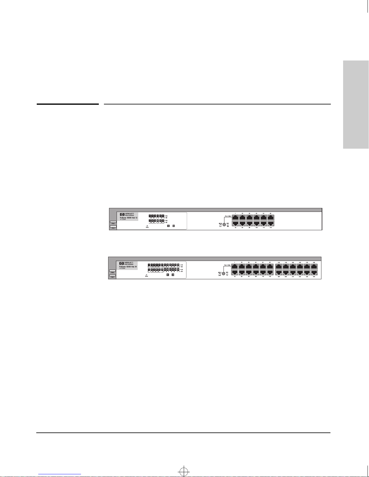
The HP ProCurve J3294A and HP J3295A 10/100 hubs are low-cost multiport,
dual-speed, 10- and 100Mbps repeaters that can be used to build highperformance workgroup networks. These hubs are completely autosensing
and autonegotiating devices that provide the flexibility of adjusting to
different speed settings. The hubs are always half-duplex. This capability is
present provided that the connecting device is autonegotiation-capable or
already configured to half-duplex, and will autonegotiate with other
autonegotiating or half-duplex devices.
1
Introducing the HP ProCurve
10/100 Hubs
The two hub models are:
Throughout this manual, these hubs will be abbreviated as the HP 10/100 hubs.
The HP 10/100 Hub 12 and Hub 24 have twelve and twenty-four dual-speed,
10/100Base-T ports, respectively.
With these hubs you can build a network infrastructure by connecting the hubs
to other hubs, switches, or routers, or you can connect computers, printers,
and servers to these hubs to provide dedicated 10- or 100Mbps bandwidth to
those devices.
1-1
Roadhw0.bk : ROADHW1.FM Page 2 Thursday, May 28, 1998 5:40 PM
Introducing the HP ProCurve 10/100 Hubs
Front of the Hubs
This chapter describes your HP 10/100 hubs:
■ Front and back of the hubs
■ Network Ports
■ Port and Hub LEDs
■ Features
10/100 Hubs
■ Hub operation overview
Introducing the HP ProCurve
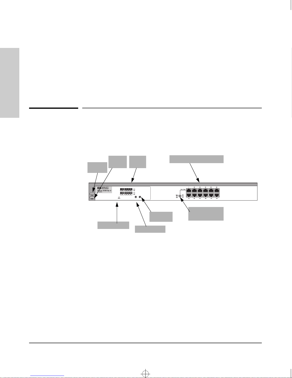
Front of the Hubs
Power
LED
Fault
LED
Reset button
Port
LEDs
Activity LED
Collision
LED
10/100Base-T RJ-45 ports
MDI/MDI-X
Button for Port 1
1-2
Roadhw0.bk : ROADHW1.FM Page 3 Thursday, May 28, 1998 5:40 PM
Introducing the HP ProCurve 10/100 Hubs
Front of the Hubs
Network Ports
The HP 10/100 Network Ports are as follows:
12 or 24 10/100Base-T RJ-45 ports
■
■ one MDI/MDI-X port (port 1).
All the fixed twisted-pair ports are wired as MDI-X. Therefore, to connect end
nodes or other MDI-type devices to these ports, use “straight-through” twistedpair cable; to connect hubs, switches, or other MDI-X-type devices to these
ports, use “crossover” twisted-pair cable. See Appendix B, “Cables and
Connectors” for descriptions of these cables. If you only have straight-through
cable, you can use port 1 with the MDI button depressed to connect hubs with
switches and other hubs. The MDI button crosses the cable pairs so that the
Transmit and Receive pins on connecting devices exchange signals correctly.
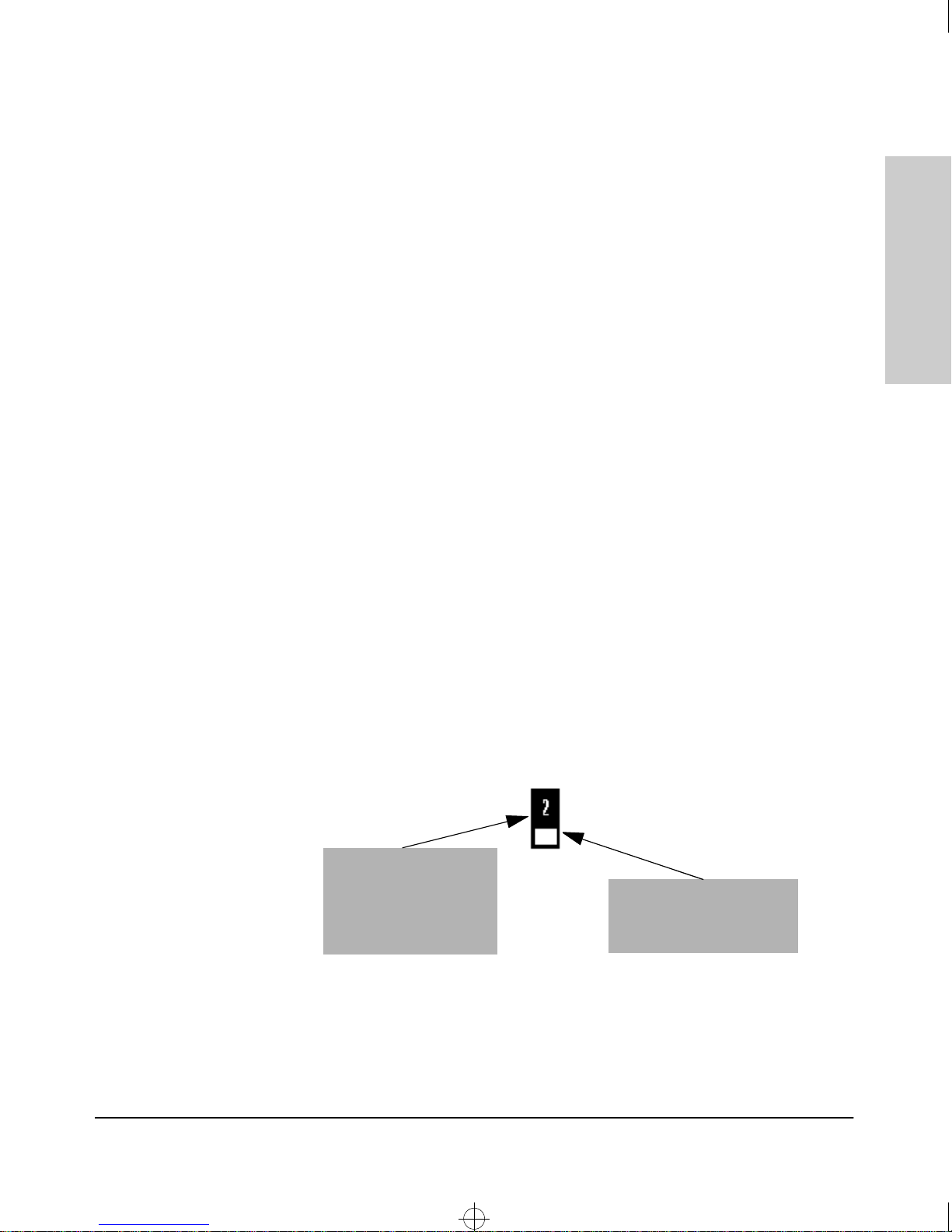
Port LED Types
There are two types of port LEDs:
Link. This LED highlights the port number. When lit, these LEDs indicate the
port has detected another device. If the 100 LED is not lit, then the Link LED
indicates a connection to an attached 10Base-T device.
Introducing the HP ProCurve
10/100 Hubs
100. This LED highlights the rectangle LED under the Link LED. When lit,
these LEDs indicate the port is connected to an attached device operating at
100Mbps. The following figure shows an HP 10/100 LED operating at 100Mbps.
See the following sections for more LED detail.
Link LED. Indicates
whether the port has
detected an attached
device. If the 100 LED is not
lit, then the device is
operating at 10Mbps
100 LED. Indicates whether
the device connected to this
port was detected to be
100Mbps.
1-3

Roadhw0.bk : ROADHW1.FM Page 4 Thursday, May 28, 1998 5:40 PM
Introducing the HP ProCurve 10/100 Hubs
Front of the Hubs
LEDs for the 10/100Base-T Hubs
To see what the LEDs for the HP 10/100 hubs do, see the following table. For
a more extended view of the LEDs, see the table under the section “LED
Combinations.”
Hub Status LED State Meaning
10/100 Hubs
Introducing the HP ProCurve
Power (Green) On The hub is receiving power.
Off The hub is NOT receiving power.
Fault (Orange) Off The normal state. Indicates that there are no fault conditions
on the hub.
On The hub is in self test after being powered on or reset. If on
for a prolonged time (after three seconds), the hub has failed
its self test.
Slow* A port has been partitioned. The Link LED of the partitioned
port also blinks.
Activity (Green) On/Blinking The hub is receiving packets. If it appears as solid, packet
traffic is heavy.
Off The hub is not receiving packets from any attached device.
Collision
(Orange)
Link LEDs
Link On The port detects an attached device.
* The slow blink behavior is a regular pulse once every 1.6 seconds, approximately.
100 LEDs
100Mbps
Indicator LED
On/Blinking The hub has detected two or more packets on the hub have
run into each other on the hub, blocking successful. If the
LED is on solid, a heavy collision rate is occurring.
Off No collisions have been detected on the hub.
Off The port has not detected another device.
Slow Blink* The port has been autopartitioned due to excessive
collisions.
On The port is operating at 100Mbps.
Off If the Link LED is lit, the port is operating at 10Mbps.
If the Link LED is not lit, no attached device is detected.
1-4
Roadhw0.bk : ROADHW1.FM Page 5 Thursday, May 28, 1998 5:40 PM
Introducing the HP ProCurve 10/100 Hubs
Back of the Hubs
LED Combinations
The following table shows the kind of activity that occurs in various LED
illumination combinations:
Link LED 100 LED What is Happening
On Off The port is operating at 10Mbps.
On - Slow Blink Off The port is operating in 10Mbps mode, but has
been partitioned due to excessive collisions.
The Fault LED will also blink.
On On The port is operating at 100Mbps.
On - Slow Blink On - Slow Blink The port is operating in100Mbps mode, but has
been partitioned due to excessive collisions.
The Fault LED will also blink.
Off Off The port does not detect another device.
Reset Button
This button is used to reset the hub while it is powered on. This action clears
any temporary error conditions that may have occurred, restarts the hub and
executes the hub self test. A typical instance of where you might use the Reset
button is in the event of a hub malfunction or error condition.
Introducing the HP ProCurve
10/100 Hubs
Back of the Hubs
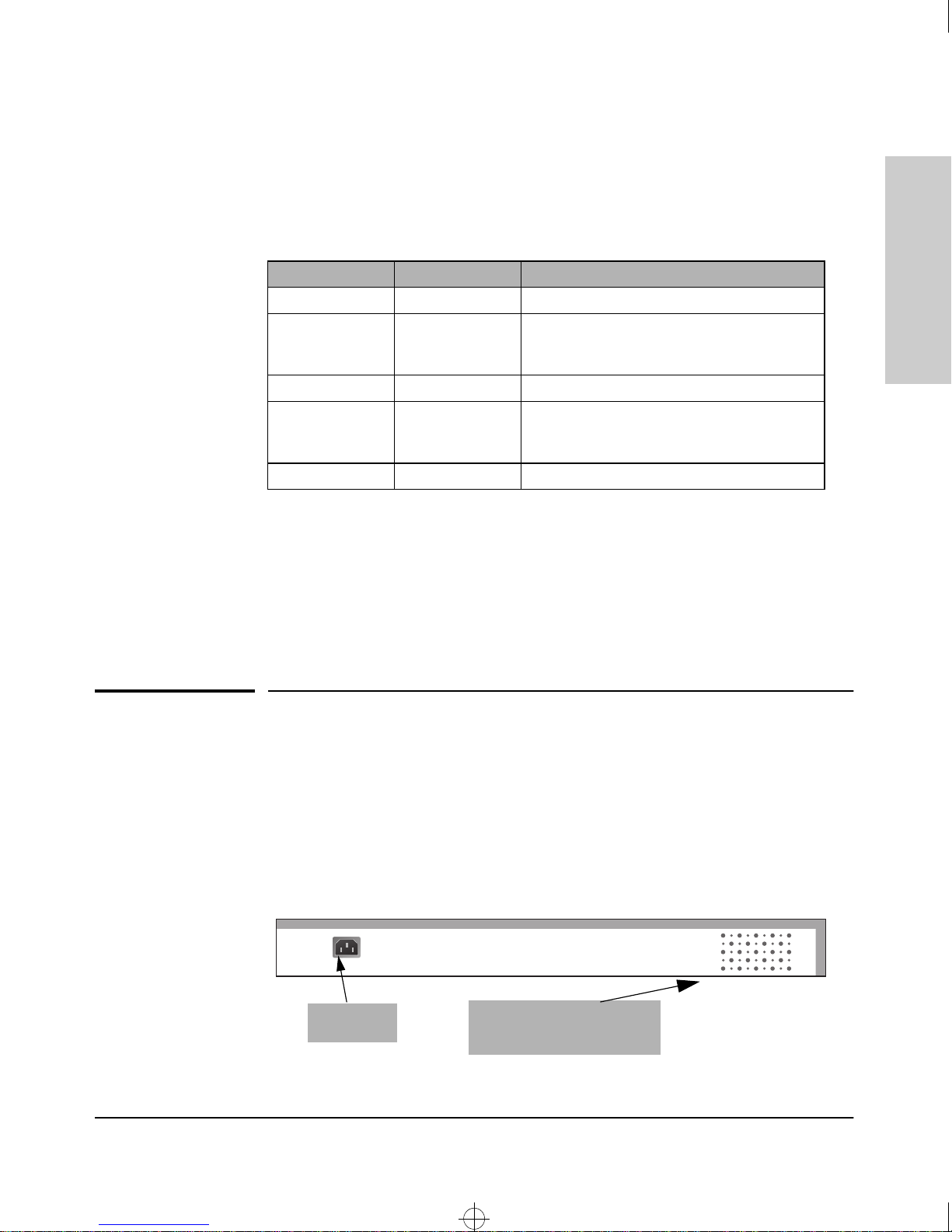
Power Connector
The 10/100 hubs do not have a power switch; they are powered on when
connected to an active AC power source. The hubs automatically adjust to
various voltages (depending on the country) between 100-127 and 200-240
volts and either 50 or 60 Hz. There are no voltage range settings required.
AC Power
Connector
Cooling vents - make sure
these are not obstructed for
proper hub operation
1-5

Roadhw0.bk : ROADHW1.FM Page 6 Thursday, May 28, 1998 5:40 PM
Introducing the HP ProCurve 10/100 Hubs
Features
The power cords and levels of power for the hub are listed below.
Country Power Cord Part Number Voltage/Hz Level
China 8120-8377 220-240 Vac, 50 Hz
USA 8120-6805 110-127 Vac, 60 Hz
Europe 8120-6802 230 Vac, 50 Hz
10/100 Hubs
Australia 8120-6803 220-240 Vac, 50 Hz
Introducing the HP ProCurve
Japan 8120-6804 100 Vac, 50/60 Hz
UK 8120-6801 220-240 Vac, 50 Hz
Switzerland 8120-6807 230 Vac, 50 Hz
Denmark 8120-6806 230 Vac, 50 Hz
Features
The features of the10/100 hubs include:
12 or 24 Ethernet 10/100Base-TX ports with RJ-45 connectors.
■
■ plug-and-play networking—all ports are enabled—just connect the
network cables to active Ethernet or Fast Ethernet network devices and
your network is operational.
■ all ports are autonegotiation-capable.
■ 12 or 24 Link LEDs with companion 100Mbps LEDs.
■ push-button MDI/MDI-X selection.
■ rack- or wall-mountable.
1-6

Roadhw0.bk : ROADHW2.FM Page 1 Thursday, May 28, 1998 5:40 PM
Installing the Hub
The HP J3294A and HP J3295A 10/100 hubs are easy-to-install units. Each
comes with an accessory kit (HP P/N 5183-7210) that includes the brackets
for mounting the hub in a standard 19-inch telco rack or an equipment cabinet,
or on a wall, and it comes with rubber feet so it can be securely located on a
horizontal surface. The brackets are designed to allow mounting the hub in a
variety of orientations.
2
This chapter shows you how to install your 10/100 hub.
Included Parts
The 10/100 hub has the following components shipped with it:
■
HP ProCurve 10/100 Hubs Installation Guide (5967-2280), this manual
■ Customer Support/Warranty booklet (5967-2242)
■ Accessory kit (5183-7210)
• two mounting brackets
• four 10 mm M4 screws to attach the mounting brackets to the hub
• four 5/8-inch number 12-24 screws to attach the hub to a rack
• four rubber feet
Power cord, one of the following:
■
Australia/New Zealand
United Kingdom
China
Continental Europe
Denmark
Japan
Switzerland
United States/Canada/Mexico
(8120-6803)
(8120-6801)
(8120-8377)
(8120-6802)
(8120-6806)
(8120-6804)
(8120-6807)
(8120-6805)
Installing the Hub
2-1

Roadhw0.bk : ROADHW2.FM Page 2 Thursday, May 28, 1998 5:40 PM
Installing the Hub
Installation Summary
Installation Summary
Follow these easy steps to install your hub. The rest of this chapter provides
details on these steps.
1. Prepare the installation site. Make sure that the physical environment
into which you will be installing the hub is properly prepared including
having the correct network cabling ready to connect to the hub, and
having a good location for the hub. Please see page 2-4 for some
installation precautions.
2. Verify that the hub passes self test. This is a simple process of plugging
the hub into a power source and observing that the LEDs on the hub’s
front panel show correct operation.
Installing the Hub
3. Mount the hub. The hub can be mounted in a 19-inch telco rack, in an
equipment cabinet, on a wall, or on a horizontal surface.
4. Connect power to the hub. Once the hub is mounted, plug it in to the
nearby main power source.
5. Connect the network devices. Using the appropriate network cables,
connect other hubs, switches, routers, computers, servers, printers, and
other network devices to the hub ports.
At this point, the hub is fully installed and your network should be up and
running. See the rest of this chapter if you need more detailed information on
any of these installation steps.
2-2

Roadhw0.bk : ROADHW2.FM Page 3 Thursday, May 28, 1998 5:40 PM
Installation Precautions
The following are power requirement precautions.
• If your installation requires a different power cord than the one supplied with the hub,
be sure to use a power cord displaying the mark of the safety agency that defines the
regulations for power cords in your country. The mark is your assurance that the power
cord can be used safely with the hub
• Do not install the hub in an environment where the operating ambient temperature might
exceed 55°C (131°F).
• The hub does not have a power switch; it is powered on when the power cord is plugged
in. The hub's power supply automatically adjusts to any AC power source between 100127 volts and 200-240 volts. There are no voltage range settings to configure.
• When installing the hub, note that the AC outlet must be installed near the equipment
and should be easily accessible.
Installing the Hub
Installation Summary
Installing the Hub
The following are mounting precautions:
• The rack or cabinet should be adequately secured to prevent it from becoming unstable
and/or falling over. The hub should be mounted in a position toward the bottom of the
rack for stability and to make it easier to stack the other hubs on top.
• Before mounting a hub, plan its location and orientation relative to other devices and
equipment. Also consider the cabling that will be attached to the hub and the ports that
will be used. Verify that there is room for the grouped cables to trail out from the side of
the hub. Allow at least 2.54 cm (1 inch) in the front of the hub. In the back of the hub,
allow at least 3.8 cm (1 1/2 inches) of space for the power cord.
• Ensure that the HP 10/100Base-TX Hub does not overload the power circuits, wiring,
and over-current protection. To determine the possibility of overloading the supply
circuits, add together the amperage ratings from the nameplates of all your hubs (and
other equipment) installed on the same circuits and compare the total with the rating
limits for the supply circuits.
• Make sure that the power source circuits are properly grounded, then use the supplied
power cord to connect the HP 10/100Base-TX Hubs to the circuit. See the Safety
Statements in this chapter.
• Do not block airflow around the sides and the back of the unit.
2-3
 Loading...