

Page 1

HP LaserJet P3010 Series Printers
Service Manual
Additional product information:
www.hp.com/support/ljp3010series
Page 2

Page 3

HP LaserJet P3010 Series Printers
Service Manual
Page 4

Copyright and License
© 2009 Copyright Hewlett-Packard
Development Company, L.P.
Trademark Credits
®
is a trademark of Adobe Systems
Adobe
Incorporated.
Reproduction, adaptation, or translation
without prior written permission is prohibited,
except as allowed under the copyright laws.
The information contained herein is subject
to change without notice.
The only warranties for HP products and
services are set forth in the express warranty
statements accompanying such products
and services. Nothing herein should be
construed as constituting an additional
warranty. HP shall not be liable for technical
or editorial errors or omissions contained
herein.
Part number: CE524-90909
Edition 1, 7/2009
Microsoft®, Windows®, Windows® XP, and
Windows Vista® are U.S. registered
trademarks of Microsoft Corporation.
ENERGY STAR and the ENERGY STAR
mark are registered U.S. marks.
Page 5

Conventions used in this guide
TIP: Tips provide helpful hi nts or sh or tcu t s.
NOTE: Notes provide important information to explain a concept or to complete a task.
CAUTION: Cautions indicate procedures that you should follow to avoid losing data or damaging the
product.
WARNING! Warnings alert you to specific procedures that you should follow to avoid personal injury,
catastrophic loss of data, or extensive damage to the product.
ENWW iii
Page 6

iv Conventions used in this guide ENWW
Page 7

Table of contents
1 Theory of operation
Basic operation ...................... ...... ....... ..... ..................................... ....... ...... ..... ...................................... 2
Major printer systems ............. ... .. ... ................. ... ... ... ................. ... .. .... ................ ... ... ... ........ 2
Printer block diagram ........................................................................................................... 2
Sequence of operation ......................................................................................................... 3
Normal sequence of operation ............................................................................ 3
Formatter-control system ................... ...... ....... .. ....... ..... ....... ...... ...... ... ....... ..... ....... ...... ...... .................. 4
Sleep mode .......................................................................................................................... 4
Input/output .......................................................................................................................... 4
CPU ..................................................................................................................................... 4
Memory ................................................................................................................................ 5
Optional hard disk ........... ... ... ... .................. ... ... ... .................. ... ... ... .................. ... 5
Firmware ............................................................................................................. 5
Nonvolatile memory ............................................................................................ 5
PJL overview ................ ... .... .. ................... .. .... ... .................. ... ... ... .................. ... ... ... ............ 5
PML ..................................................................................................................................... 5
Control panel ............ .... ... .................. ... ... ... .................. ... ... ... .................. .... ... .. ................... 5
Engine-control system .............. .... ..... ..... .............................. ..... ..... .... ............................... ................... 6
Motors, fans, clutches, solenoids, switches, and sensors .... ............. .. .. .. ............. .. .. .. ......... 7
DC controller operations ................ .... ...................... .... .... .... ...................... .... .... ... ............. 14
Fuser-control circuit .............. ... ... ................... .... ... .... ................... ... ... ... .................... ... ...... 16
Fuser failure detection ....................................................................................... 17
Fuser temperature control ................................................................................. 18
Fuser protective function ................................................................................... 19
Low-voltage power supply ................................................................................................. 20
Overcurrent/overvoltage protection ................ ............ ....... ........... ........... .......... 21
High-voltage power supply ................ ..... ..... ....... ................................. ..... ....... ..... ............. 22
Formatter ........................................................................................................................... 23
Formatter heartbeat LED .................................................................................. 23
DIMM slots .................. ... ................... ... ... .... .................. ... .... .. ................... ... ... .. 23
Laser/scanner system ................................................. ....... ..... ..... .................................... .. 24
Laser failure detection ................ ... .... ..... ... ......................... ..... ... ..... .................. 25
Image-formation system ........... ..... ..... ............................. ..... ..... ..... ............................. ..... ......... ..... .... 26
Electrophotographic process ........... ...... ...... ....... ..... ....... .. ....... ...... ...... ...... ...... ... ...... ....... .. 26
ENWW v
Page 8

Image formation process ................................................................................................... 27
Latent-image formation stage ........................................................................... 28
Primary charging .............................................................................. 28
Laser beam exposure ............... ...................... .... .... ... ...................... . 28
Developing stage .............................................................................................. 29
Print cartridge ................................................................................... 29
Transfer stage ................................................................................................... 30
Fusing stage ................ ... .................... ... ... ... ................... ... ... ... ......... 30
Cleaning stage .................................................................................. 31
Toner detection ................... ... ..... ..... ..... ............................ ..... ... ..... ............................ ........ 32
Pickup, feed, and delivery system ........................................... .... .... ...... ............................. .... ............ 33
Paper trays .................................... .... ... .. ................... ... ... ... ................... .. ... ... .................... 33
Photo sensors and switches ............ .... ... .... .... ...................... ... .... ... ....................... .... ... .... . 34
Solenoids and clutches ......................................... ... ..... ..... ........................... .... ...... .... ....... 36
Tray 1 or Tray 2 .................................................................................................................................. 38
Pickup and feed unit ................ ... .... ... ... .................... ... ... ... .................... ... .... ... .................. 38
Cassette paper size detection/cassett e pape r detec tion ............................. ...... 38
Cassette pickup ................................................................................................. 38
Tray 1 paper pickup ........................................................................................................... 38
Paper pickup and feed ....................................................................................................... 39
Jam detection ................ .................. .. ... .... .................. .. ... .... ................. ... ... ... .................... 40
Additional tray .......................... ..................................... ....... ...... ..... .................................................... 41
Tray driver PCA ......................................... ... .... ... .................... ... .... ... .................... .... ... ..... 41
Paper pickup and feed ....................................................................................................... 42
Media level and size detection ........................................................................................... 43
Jam detection ................ .................. .. ... .... .................. .. ... .... ................. ... ... ... .................... 43
2 Removal and replacement
Removal and replacement strategy ................................................................................................... 46
General cautions during removal and replacement ........................................................... 46
Electrostatic discharge ...................................................................................... 46
Required tools ................................................................................................... 46
Types of screws ................... .... ... .................. .. .... .................. .. ... ... .................. .. 47
Service approach ............... .... ... .................... ... ... ... ................... .... ... .... ................... ... ... ..................... 48
Before performing service .................................................................................................. 48
After performing service ............................... ...... ..... ..... ................................... ...... ..... ........ 48
Post-service test ..................... ... .................... ... .... ... .................... ... ... ... ..................... ... ..... 48
Print-quality test ...... .. ... ... .. ................ .. ... ... ............... ... .. ... ............... ... ... .. .......... 48
Parts removal order ........................................................................................................... 50
Removal and replacement procedures .................... .... .. ... ................. .. ... ... ................ ... ... .. ................ 52
Print cartridge, cassettes, and sub cover ........................................................................... 52
Print cartridge .................................................................................................... 52
Tray cassette (Tray 2, Tray 3, or Tray 4) .......................................................... 54
vi ENWW
Page 9

Sub cover ....................... .... ... .... ...................... .... .... ... ..................... .... .... .... ...... 55
External panels, covers, doors, formatter PCA, DIMM, and EIO disk ............................... 56
EIO disk ............................... ..... ..... ...... ...... ................................ ..... ..... ....... ....... 56
DIMM cover and DIMM ..................................................................................... 57
Reinstall the DIMM ........................................................................... 58
Formatter cover and formatter PCA .................................................................. 60
Rear-door assembly ..................... ..... ... ......................... ..... ... ......................... ... 62
Left cover .......................................................................................................... 66
Right-rear cover .............. ... .. ... .. ................ .. ... ... ............... ... .. ... ............... ... ... .... 68
Tray 1 (multipurpose tray) cover .............. ... .. .. ............... ... .. ... ............... ... .. ... .... 69
Cartridge-door assembly .................... ......... ... ........ ........ ......... ....... ........ .... ....... 71
Top-right cover ...................... ..................... ... .... ... ...................... ... .... ... ............. 73
Control panel ..................... ......................... ..... .... .... .......................... .... ..... .... ... 74
Front-right and right-side cover assembly ........................... ... .... ... .................... 76
Lower-right cover and bracket ...................... ..... ..... ..... ..... ............................... .. 80
Reinstall the lower-right cover ........ .. ............ ... .. .. ............ ... .. .. .......... 82
Top cover ...................................... ... ... ... ................... ... ... ... ................... ... ... .... .. 84
Main assemblies ............ .... .... .... .... ....................... .... .... .... ....................... .... .... .... .............. 86
Tray 1 (multipurpose tray) pickup roller .................... .... .... ............................. .... 86
Tray 1 (multipurpose tray) separation pad ......... ............. .. .. .. ............. .. ... .. ........ 87
Tray 2, Tray 3, or Tray 4 pickup roller ................... ... ... ... ................ .... .. ... .......... 88
Tray 2, Tray 3, or Tray 4 separation pad ............. ..... ..... ..... ............................. .. 90
Tray 2, Tray 3, or Tray 4 base-plate ro ller assembly ........................................ 91
Transfer roller ......................... .... .......................... ... ...... ... .......................... .... ... 92
USB port PCA ................................................................................................... 94
Power-switch assembly .................... ............................... ..... ..... ..... ................... 96
Main fan, fan duct, and environmental sensor .................................................. 98
Fuser ............................................................................................................... 100
Registration assembly ..................................................................................... 102
Duplex media-feed assembly ........ ... ..... ....................... ... .... .... ........................ 104
Laser/scanner ................................................................................................. 107
Engine control unit (ECU) ............................................................................... 110
Cassette pickup (Tray 2) solenoid or Tray 1 (multipu rpose tray) pickup
solenoid ................... .... ..... ... ........................... .... ..... .... .......................... ..... ..... 115
Fuser motor ..................................................................................................... 117
Sub fan and fan duct ....................................................................................... 118
High-voltage power supply (HVPS) ................................................................. 121
3 Solve problems
Solve problems checklist ............... ..... ..... ..... ..... ............................. ...... .... ..... ................................... 128
Menu map ........................................................................................................................................ 130
Troubleshooting process ............................ ............ ............ ............. ............ ..... ............. ................... 131
Determine the problem source ........................................................................................ 131
Power subsystem ................... ....................... ..... ... .... ...................... .... .... ..... ................... 132
ENWW vii
Page 10

Power-on checks ............................................................................................. 132
Tools for troubleshooting .................................................................................................................. 133
Individual component diagnos tics ...... ..... ......................... .......................... ...................... 133
LED diagnostics .............................................................................................. 133
LED indicators ................................................................................ 133
Formatter heartbeat LED ............ ..................... ... .... ... .................... . 133
HP Jetdirect LEDs .......................................................................... 134
Engine diagnostics .......................................................................................... 134
Engine-test button .......................................................................... 134
Fuser test page ................. ... ................. ... .... .. .................. ... ... ... .................. ... . 135
Paper-path test (and automatic sensors test) .......... ....................................... 136
Sensor test (interactive) .................................................................................. 137
A TOP (Top-of-Page) sensor ............................... ..... .... ..... ............. 140
B Fuser output sensor .................................................................... 141
C Duplex sensor ................ ... ... .................. .... .. ... .................. .... ... ... 142
D Paper width sensor 1 .................................................................. 143
E Tray 3 feed sensor ...................................................................... 144
F Tray 4 feed sensor ...................................................................... 145
G FD tray full sensor ................................ ..... ...... ... ......................... 146
H Face up detect sensor ...... .......................................................... 147
I Cartridge-door open switch .......................................................... 148
J Rear cover open sensor .............................................................. 149
K Tray 1 paper sensor .................................................................... 150
L Tray 2 paper sensor ..................... ............ ............ ....................... 151
M Tray 2 detect switch .................................................................... 152
N Tray 3 paper sensor ...................... ... ..................... .... ... .... ........... 153
O Tray 3 detect switch .................................................................... 154
P Tray 4 paper sensor .................................................................... 155
Q Tray 4 detect switch .................................................................... 156
Print/stop test ............. ... ... ... ... .................. ... ... ... .................. .... ... .. ................... 157
Component tests ............................................................................................. 158
Half self-test .................... ..... ..... .... ..... ............................. ..... ..... ..... . 158
Drum rotation test check ................................................................. 158
Diagnostics menu components test ..... .... ......................... .............. 158
Diagrams ......................................................................................................................... 160
Block diagrams ................................................................................................ 160
Plug/jack locations .......................................................................................... 162
Location of connectors .............. ................... .... ... .... .................... ... .... ... .......... 163
ECU controller connections ....... ............... ... ... .. ................ .. ... .. ....... 163
Locations of major components ...................................................................... 165
General timing charts ...................................................................................... 169
General circuit diagram ........... ... ... ... .................... ... ... .... ................... .... ... ... .... 170
Internal print quality test pages ............. ..... .... ..... .......................... ..... ... ..... ...................... 171
Cleaning page ............... ... ...................... ... .... ... ..................... .... ... .... ............... 172
viii ENWW
Page 11

Configuration page .............. ........................ .... ..... ... .......................... .... .... .... .. 172
Print quality troubleshooting tools .................................................................................... 173
Repetitive image-defect ruler ... ... ............... ................ ............... ................ ...... 173
Control-panel menus ....................................................................................................... 174
Use the menus ................................................................................................ 174
Show Me How menu ....................................................................................... 174
Retrieve job menu ........................................................................................... 175
Information menu ............................................................................................ 176
Paper handling menu ......... .. .. ... ............... .. .. ... ............... .. .. ... ............... .. .. ... .... 177
Manage supplies menu ................................................................................... 177
Configure device menu .......... ................. ... .. ... ................. .. ... ... ................. .. .... 178
Printing menu ................................................................................. 178
Print Quality menu .......... ............. .. .. ... ............ .. ... .. ............. .. .. .. ...... 180
System setup menu ........................................................................ 183
I/O menu ......................................................................................... 187
Resets menu ........................ .. .. .. .............. .. .. ... .............. .. .. ... .......... 194
Diagnostics menu ............................................................................................ 194
Service menu .................................................................................................. 196
Interpret control-panel messages ..... ................. ... ... ... ................. ... .. .... ................. ... ... .. .. 197
Control-panel message types ......................................................................... 197
Control-panel messages ................................................................................. 197
Event-log messages ........................................................................................................ 215
Print an event log ............................................................................................ 215
Show an event log ................. ... .... ... .................... .... ... .... ..................... ... ... .... .. 215
Sample event-log page ....... .. ... ... .. ................. ... ... ... ................ ... ... ... ............... 216
Clear an event log ........................................................................................... 216
Event-log messages ........................................................................................ 217
Clear jams ................... ...................... .... .... ... ....................... ... .... ... ....................... .... ... ..................... 219
Common causes of jams ................................................................................................. 219
Jam locations ............... ... ... .... .... .................... ... ... .... .................... ... .... ... ..................... ..... 220
Clear jams from the input trays ........................................................................................ 222
Clear jams from the duplexer ........................................................................................... 226
Clear jams from the output areas .................................................................................... 231
Clear jams from inside the product .................................................................................. 234
Registration and transfer area ............................ .... .. ... ................... ... ... .... ....... 234
Jam causes and solutions ............................................................................................... 236
Avoid repeated jams ....................................................................................................... 240
Change jam recovery ....................................................................................................... 241
Solve paper-handling problems ........................................................................................................ 242
Product feeds multiple sheets .......................................................................................... 242
Product feeds incorrect page size ........... .. .. ... .. ............... ... .. .. ............... ... ... .. ............... ... 242
Product pulls from incorrect tray ........................ ... .. ... ............... .. ... .. ............... .. ... ... ......... 243
Paper does not feed automatically .................................................................................. 243
Paper does not feed from Tray 2, 3, or 4 ......................................................................... 244
ENWW ix
Page 12

Transparencies or glossy paper will not feed ........ .. ............. .. .. .. ............. .. .. .. ............. .. ... 244
Envelopes jam or will not feed in the product .................................................................. 245
Output is curled or wrinkled ............................................................................................. 245
Product does not duplex or duplexes incorrectly (dupl ex models) .................................. 246
Solve image-quality problems ........ .................... ... ... .... ..................... ... ... ... ..................... ... .... .......... 247
Image defect examples .................... ..... ..... ....... ................................. ....... ..... ....... ........... 247
Clean the product ............................................................................................................................. 254
Solve performance problems ........................................................................................................... 257
Solve connectivity problems ............. .... ............................. .... ..... ..... ............................. ..... ..... .......... 258
Solve direct-connect problems ..... ... ............... ................ ............... ............... ................ ... 258
Solve network problems .................................................................................................. 258
Service mode functions .................................................................................................................... 259
Service menu ...................... .... .... ..... ..... ............................ ..... ..... ... ............................. ..... 259
Product resets ................................ ....... ..... ................................... ..... ....... ..... .................. 260
Restore factory settings .......... ... .............. .. ... .. .............. ... .. .. ............... .. ... .. ..... 260
Hard disk initialization ....... ... .. .. ... .............. ... .. .. ............... ... .. .. ............... .. ... .. ... 260
Skip disk-load .................................................................................................. 260
NVRAM initialization ........................................................................................ 260
Service ID ....................................................................................... 261
Restore service ID .......................................................................... 261
Convert the service ID to an actual date ........................................ 261
Reset serial number ....................................................................... 262
Reset page counts .......................................................................... 262
Product cold reset ........................................................................................... 262
Product updates ................................... .... ... .... ...................... .... ... .... ...................... .... .... .................. 263
Determine the current firmware version .................... ..... ..... .................................. ..... ...... 263
Download new firmware from the HP Web site ............................................................... 263
Transfer the new firmware to the product .................. ... ... ... ................... .... ... ... ................ 263
Use the flash executable file to update the firmware ...................................... 263
Use FTP to upload t he firmware throug h a browser ....................................... 264
Use FTP to upgrade the firmware on a networ k conne cti on ......... . ........ ........ . 264
Use HP Web Jetadmin to upgrade the firmware ............................................. 265
Use Microsoft Windows commands to upgrade the firmware ......................... 265
Upgrade the HP Jetdirect firmware ...................................................... ..... ...... ...... ........... 265
4 Parts and diagrams
Order parts by authorized se rv ic e prov id er s .............. ...................................................................... 268
Order parts, accessories, and supplies ....... ... .. .............. .. ... .. .............. .. ... .. .............. .. .. ... 268
Related documentation and software .............................................................................. 268
Supplies part numbers ..................................................................................................... 268
Accessories part numbers ........... ... ... .... .................. ... ... ... .................. ... .... ... .................. . 269
Whole-unit replacement part numbers ............................................................................. 270
How to use the parts lists and diagrams .......................................................................................... 271
x ENWW
Page 13

Assembly locations ........................ ....... ..... ....... ...... ..................................... ..... ....... ...... ................... 272
Base product (no optional trays or accessories) .............................................................. 272
Base product (optional trays or accessories) ................................................................... 273
Covers .............................................................................................................................................. 274
Internal assemblies (1 of 6) .............................................................................................................. 276
Internal assemblies (2 of 6) .............................................................................................................. 278
Internal assemblies (3 of 6) .............................................................................................................. 280
Internal assemblies (4 of 6) .............................................................................................................. 282
Internal assemblies (5 of 6) .............................................................................................................. 284
Internal assemblies (6 of 6) .............................................................................................................. 286
Input devices .................................................................................................................................... 288
500-sheet input tray (Tray 3 and Tray 4) ......................................................................... 288
Alphabetical parts list ....................................................................................................................... 290
Numerical parts list ........................................................................................................................... 293
Appendix A Service and support
Hewlett-Packard limited warranty statement ... .. ................ ... .. ... ............... .. ... .. ................ ... .. ... ......... 298
HP's Premium Protecti on W arran ty: LaserJet print cartridg e li mited warranty statement . .... .... . ...... 299
End User License Agreement .......................................................................................................... 300
Customer self-repair warranty service ............................. .... ... .... ....................... ... .... ... ..................... 302
Customer support .............. ... .... .... ..................... .... ... .... ...................... .... ... .... ................................... 303
Repack the product .......................................................................................................................... 304
Service information form .................................................................................................................. 305
Appendix B Specifications
Physical specifications .............. ...... .... ..... ....... ...... ...... ...... .... ..... ....... ...... ...... ...... .... ..... .................... 308
Electrical specifications ............. ....... ....... ....... ....... ... ....... ....... ....... ....... ....... ... ........ ....... ................... 308
Acoustic specifications ...... .... ... .... ..................... .... ... .... ..................... ... .... ... ..................... ................ 308
Environmental specifications ....... ....... ....... ....... .... ...... ....... ....... ...... ........ ... ....... ....... ...... ....... ............ 309
Appendix C Regulatory information
FCC regulations ............. .... ... .. .................... ... .... ... ................... ... ... .... ................... ... ... ... .................. 312
Environmental product ste war dship program ................................................................................... 313
Protecting the environment ......... ... ... .................. .... ... .. ................... ... ... .... .................. ... .. 313
Ozone production ............ ... ... ... .. .................. ... ... ... ................. ... ... ... ................. .. .... .. ... .... 313
Power consumption ......................................................................................................... 313
Toner consumption .......................................................................................................... 313
Paper use .................. ... ... ... ... .................. .... ... .. ................... ... ... ... ................... .. ... .... ....... 313
Plastics ............................................................................................................................ 313
HP LaserJet print supplies ............................................................................................... 313
Return and recycling instructions ..................................................................................... 314
United States and Puerto Rico ........................................................................ 314
Multiple returns (more than one cartridge) ..................................... 314
ENWW xi
Page 14

Single returns ................................................................................. 314
Shipping .......................................................................................... 314
Non-U.S. returns ............................................................................................. 314
Paper ............................................................................................................................... 314
Material restrictions ..................................................... ....... ..... ..... .................................... 315
Disposal of waste equipment by users in private households in the European Union .... 315
Chemical substances ....................................................................................................... 315
Material Safety Data Sheet (MSDS) ................................................................................ 316
For more information ....................................................................................................... 316
Declaration of conformity ..................... ..................................... ...... ..... ....... ...................................... 317
Safety statements ........................... ...... ..................................... ..... ....... ....... .................................... 318
Laser safety ............................ ............................. .... ..... ..... ........................... ...... ..... .... .... 318
Canadian DOC regulations ............. .... ..... .... ........................... .... ..... .... ........................... . 318
VCCI statement (Japan) .................................................................................................. 318
Power cord statement (Japan) ......................................................................................... 318
EMC statement (Korea) ................................................................................................... 318
Laser statement for Finland ............................................................................................. 319
Substances Table (China) ............................................................................................... 320
Index ........................................ ..... ....... ...................................... ....... ...... ....... ................................................... 321
xii ENWW
Page 15

1 Theory of operation
Basic operation
●
Formatter-control system
●
Engine-control system
●
Image-formation system
●
Pickup, feed, and delivery system
●
Tray 1 or Tray 2
●
Additional tray
●
ENWW 1
Page 16

Basic operation
Major printer systems
The product contains the following five systems:
Engine-control s y ste m
●
Laser/scanner system
●
Image-formation sys tem
●
Media feed system
●
Option
●
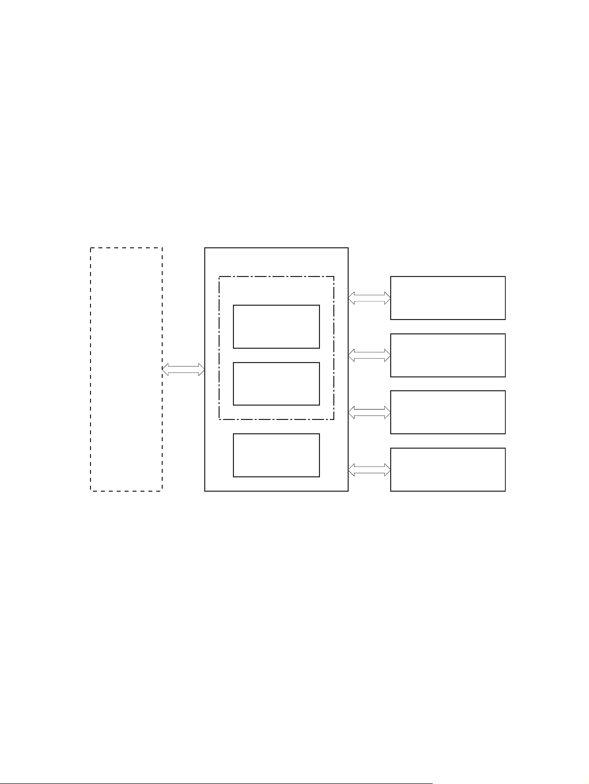
Printer block diagram
Figure 1-1 Printer block diagram
LASER SCANNER SYSTEM
ENGINE CONTROL SYSTEM
IMAGE-FORMATION SYSTEM
MEDIA FEED SYSTEM
OPTION
2 Chapter 1 Theory of operation ENWW
Page 17

Sequence of operation
The DC controller in the engine-control system controls the operational sequences of the printer. The
table below describes durations and operations for each period of a print operation from when the printer
is turned on until the motor stops rotating
Normal sequence of operation
Table 1-1 Sequence of operation
Name Timing Purpose
WAIT From the time the power switch is turned on or the
STBY (standby) From the end of the WAIT or LSTR period until either
INTR (initial
rotation)
PRINT From the end of the INTR period until the last sheet
LSTR (last
rotation)
door is closed until the printer is ready for a print
operation.
a print command is sent or the power switch is turned
off.
From the time the print command is received until the
temperature of the fuser unit reaches its targeted
temperature.
completes the fuser operation.
From the end of the PRINT period until the main motor
stops rotating.
Brings the product to printable condition. The product
performs the following during the operation:
Detects the print cartridge
●
Maintains the product in printable condition.
Starts up the high-voltage biases, the laser/scanner
and the fuser unit for printing.
Forms the image on the photosensitive drum based
on the VIDEO signals from the formatter. Transfers
and fuses the toner image to the paper.
Moves the last printed sheet out of the product.
The product enters the INTR period as the LSTR
period is completed, if the formatter sends another
print command.
ENWW Basic operation 3
Page 18

Formatter-control system
The formatter is responsible for the following procedures:
Controlling sleep mod e
●
Receiving and processing print data from the various product interfaces
●
Monitoring control-pa nel f unc tio ns an d re lay in g pro duc t- sta tus info rm ati on (through the control
●
panel and the network or bidirectional interface)
Developing and coordinatin g data pl acement and timing with the DC control ler PCA
●
Storing font information
●
Communicating with the host computer through the network or the bidirectional interface
●
The formatter receives a print job from the network or bidirectional interface and separates it into image
information and instruc tio ns tha t control the pri nti ng pr oc es s. The DC controller PCA synchr oni ze s the
image-formation system with the paper-input and -output systems, and then signals the formatter to
send the print-image data.
The formatter also provides the electr ic al inter fac e and mo unti ng loc ati ons f or one EIO ca rd an d an
additional DIMM.
Sleep mode
NOTE: In the SYSTEM SETUP menu, this item is termed SLEE P DELAY.
This feature conserves power after the product has been idle for an adjustable period of time. When the
product is in SLEEP DELAY, the control-panel backlight is turned off, but the product retains all settings,
downloaded fonts, and macros. The default setting is for SLEEP DELAY to be enabled, and the product
enters SLEEP DELAY after a 30-minute idle time.
The product exists SLEEP DELAY and enters the warm-up cycle when any of the following events
occur:
A print job, valid data, or a PML or PJL command is received
●
A control-panel button is pressed
●
A cover is opened
●
A paper tray is opened
●
The engine-test switch is pres s ed
●
NOTE: Product error messages override the Sl eep me ssage. The product enters SLEEP DELAY at
the appropriate time, but the error message continues to appear.
Input/output
The product receives print data primarily from the embedded HP Jetdirect print server. The product also
has a USB 2.0 port for connecting directly to a computer.
CPU
The formatter incorporate s a 540 MHz Co ldfi r e proce ssor .
4 Chapter 1 Theory of operation ENWW
Page 19

Memory
The random access memory (RAM) on the formatter PCA contains the page, I/O buffers, and the font
storage area. It stores printin g and font in for mat ion rece iv ed fr om the host sy ste m, and can also serve
to temporarily store a full page of print-image data before the data is sent to the print engine. Memory
capacity can be increased by adding a DIMM to the formatter. Note that adding memory might also
increase the print speed for complex graphics.
NOTE: If the product encounters a problem when managing avai la ble memo ry , a cl ear abl e war ni ng
message appears on the control-panel display.
Optional hard disk
This product supports an opti onal EIO hard disk or an optional se cur e ha rd di sk as an accessory.
Firmware
The firmware is contained on NAND flash memory soldered on the formatter board. A remote firmware
upgrade process is available, which overwrites the firmware in the NAND flash.
Nonvolatile memory
The product uses nonvolatile memory (NVRAM) to store device and user configuration settings. The
contents of NVRAM are retained when the product is turned off or disconnected.
PJL overview
The printer job language (PJL) is an integral part of configuration, in addition to the standard printer
command language (PCL). With standard cabling, the product can use PJL to perform a variety of
functions such as thes e:
Two-way communication with the host computer through a network connection or a USB
●
connection. The product can inform the hos t abou t suc h thin gs as the co ntr ol- pa nel sett ing s, and
the control-panel settings can be changed from the host.
Dynamic I/O switching. The product uses this switching to be configured with a host on each I/O.
●
The product can receive data from more than one I/O simultaneously, until the I/O buffer is full.
This can occur even when the product is offline.
Context-sensitive switching. The product can automatically recognize the personality (PS or PCL)
●
of each job and configure itself to serve that personality.
Isolation of print environment settings from one print job to the next. For example, if a print job is
●
sent to the product in landscape mode, the subsequent print jobs print in landscape mode only if
they are formatted for landscape printing.
PML
The printer management language (PML) allows remote configuration and status read-back through the
I/O ports.
Control panel
The formatter sends and receives product status and command data to and from the control-panel PCA.
ENWW Formatter-control s yste m 5
Page 20
Engine-control system
The engine-control system coordinates all product functions, according to commands that the formatter
sends. The engine-cont rol syst em drive s the laser/scanner sys tem , the im age for m atio n sy stem, and
the pickup/feed/del iver y s y stem.
The engine control system contains the following major components:
Engine-control uni t (E CU)
●
DC controller
◦
Low-voltage power supply
◦
High-vol tage power supply
●
Figure 1-2 Engine-control syst em
ENGINE CONTROL SYSTEM
Formatter
Engine controller
LASER SCANNER SYSTEM
DC controller
IMAGE-FORMATION SYSTEM
Low-voltage
power supply
MEDIA FEED SYSTEM
High-voltage
power supply
OPTION
6 Chapter 1 Theory of operation ENWW
Page 21

Motors, fans, clutches, solenoids, switches, and sensors
Figure 1-3 Motors
Fuser motor
Main motor
Table 1-2 Motors
Description Components driven Fault detection
Main motor (M8001)
Fuser motor (M8002)
Pickup roller
●
Feed roller
●
Transfer roller
●
Photosensitive drum
●
Developing roller
●
Duplex repickup roller (duplex models only)
●
Pressure roller
●
Delivery roller
●
Fuser-delivery roller
●
Duplex-feed roller (duplex models only)
●
Yes
Yes
ENWW Engine-control s y ste m 7
Page 22
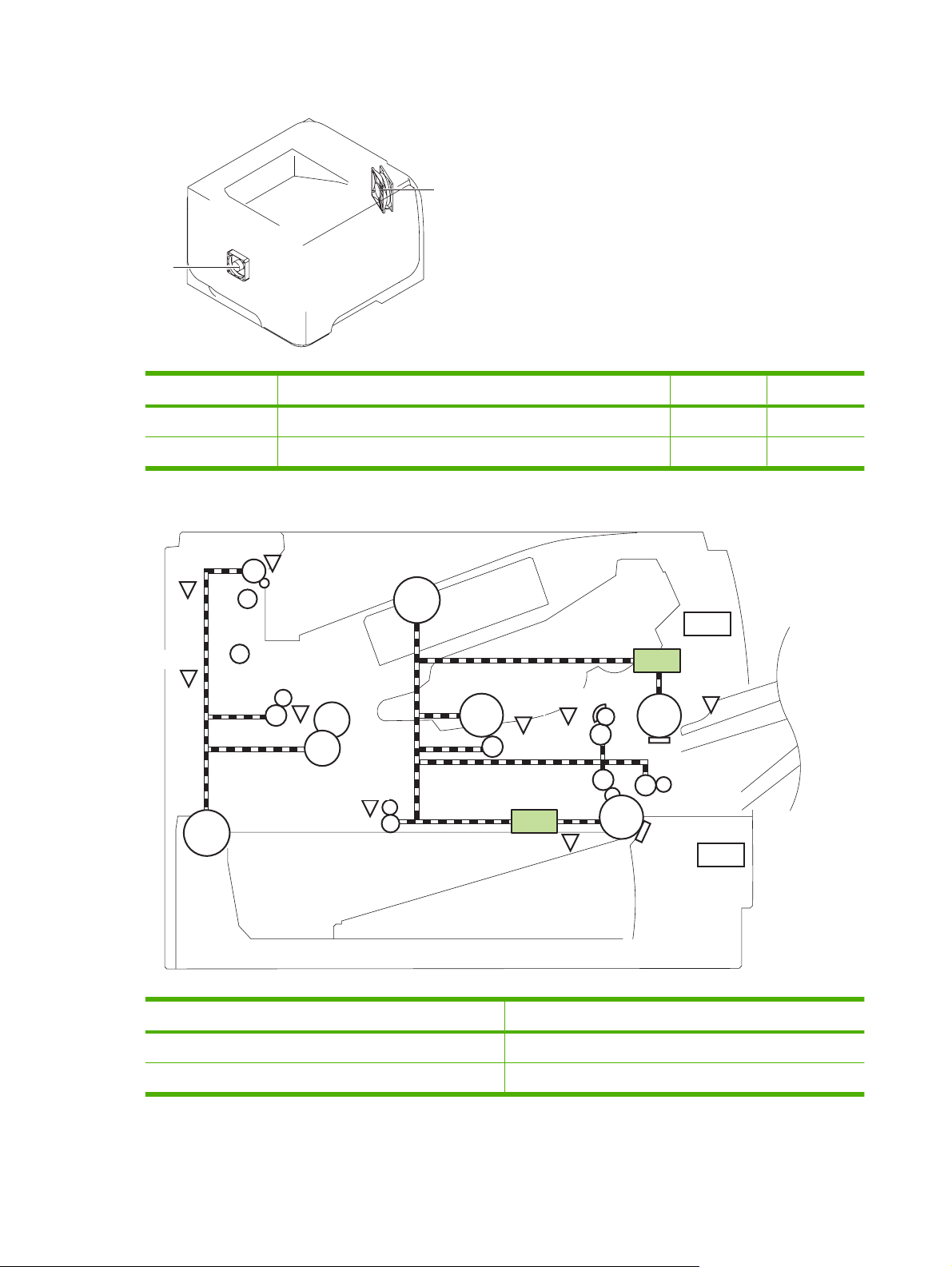
Figure 1-4 Fans
Main fan
Sub fan
Table 1-3 Fans
Description Area cooled Type Speed
Main fan (FM1) Inside the product Intake Full
Sub fan (FM2) Inside the product Intake Full
Figure 1-5 Solenoids and clutches (product)
PS4
PS1
M8001
SW501
PS8001
M8002
PS2
PS502
PS225
SL2
PS215
PS3
SL1
PS205
SW235
Table 1-4 Solenoids and clutches (product)
Item Description
SL1 Tray 1 (multipurpose tray) pickup solenoid
SL2 Cassette (Tray 2) pickup solenoid
8 Chapter 1 Theory of operation ENWW
Page 23
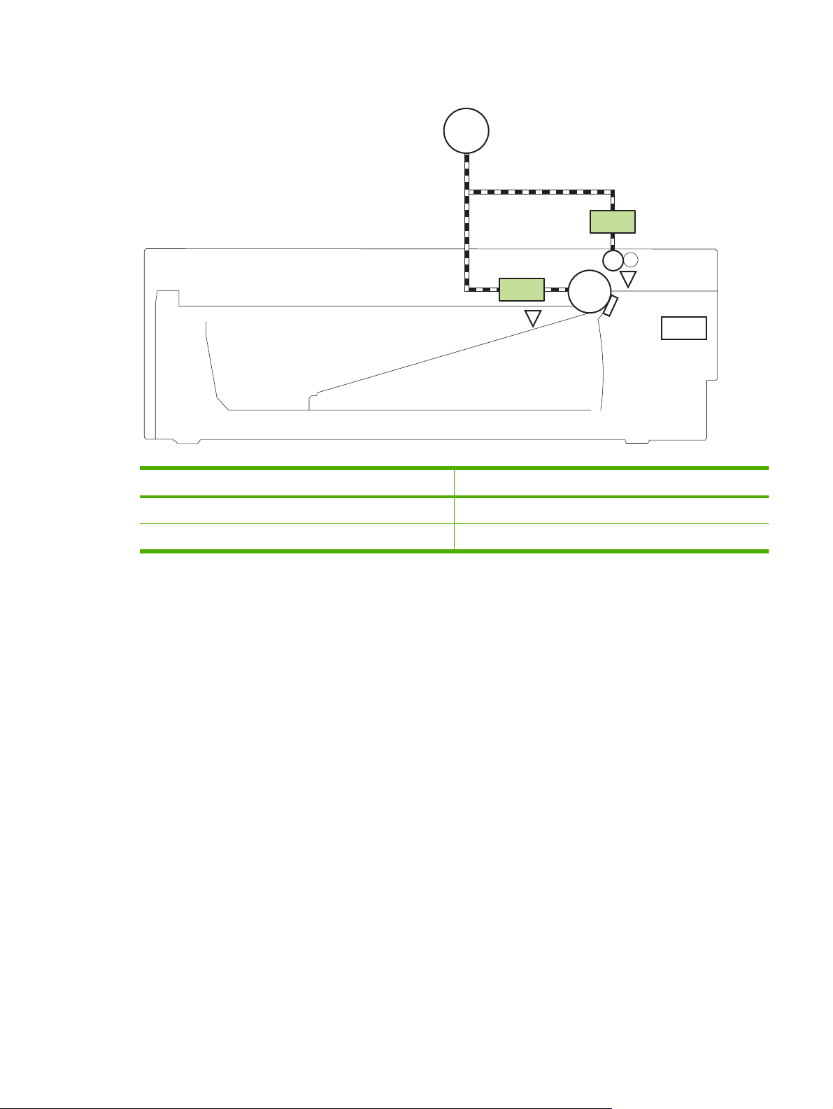
Figure 1-6 Solenoids and clutches (Tray 3 and Tray 4)
M8001
CL1
SL3
PS451
Table 1-5 Solenoids and clutches (Tray 3 and Tray 4)
Item Description
SL3 Paper feeder pickup solenoid
CL1 Paper feeder pickup clutch
1
Tray 3 and Tray 4 are identical 500-sheet input trays.
PS8008
SW461
ENWW Engine-control s y ste m 9
Page 24
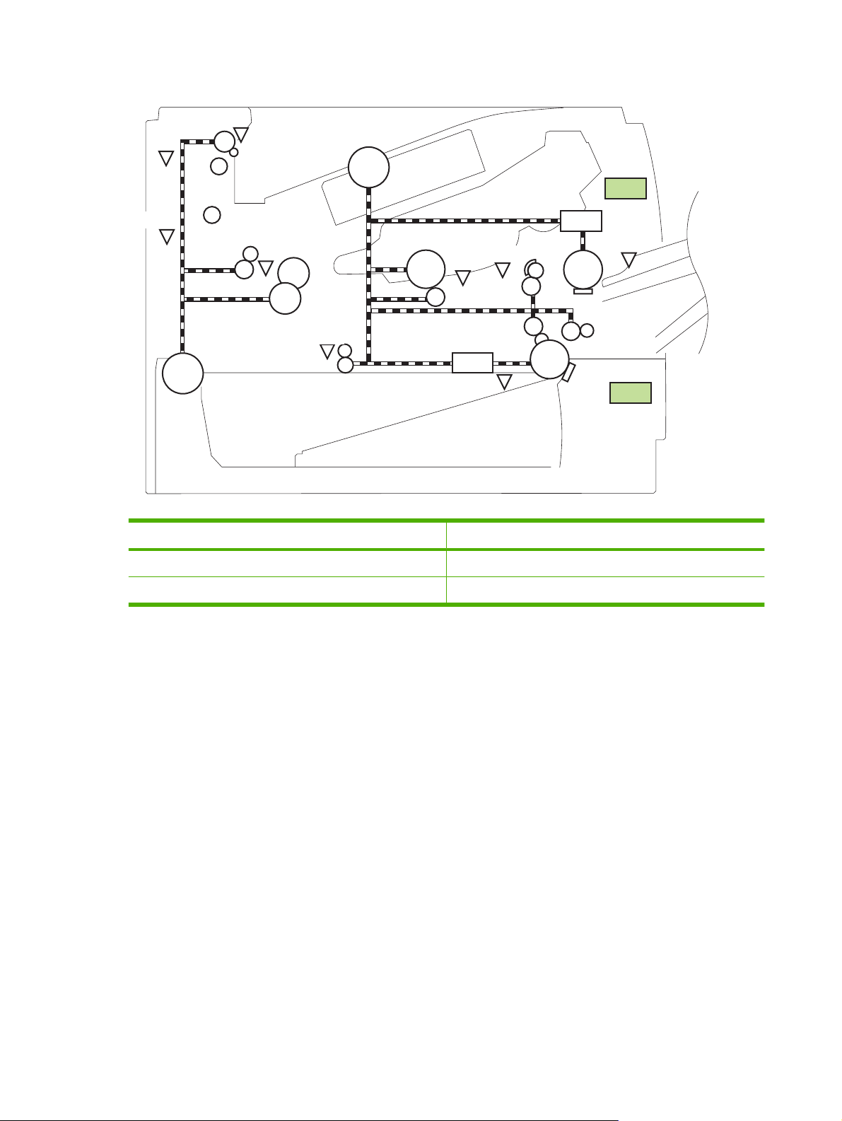
Figure 1-7 Switches (product)
PS4
PS1
M8001
SW501
PS8001
PS2
PS502
M8002
PS225
SL2
PS215
PS3
Table 1-6 Switches (product)
Item Description
SW235 Cassette presence switch
SW501 Cartridge-door switch
SL1
PS205
SW235
10 Chapter 1 Theory of operation ENWW
Page 25
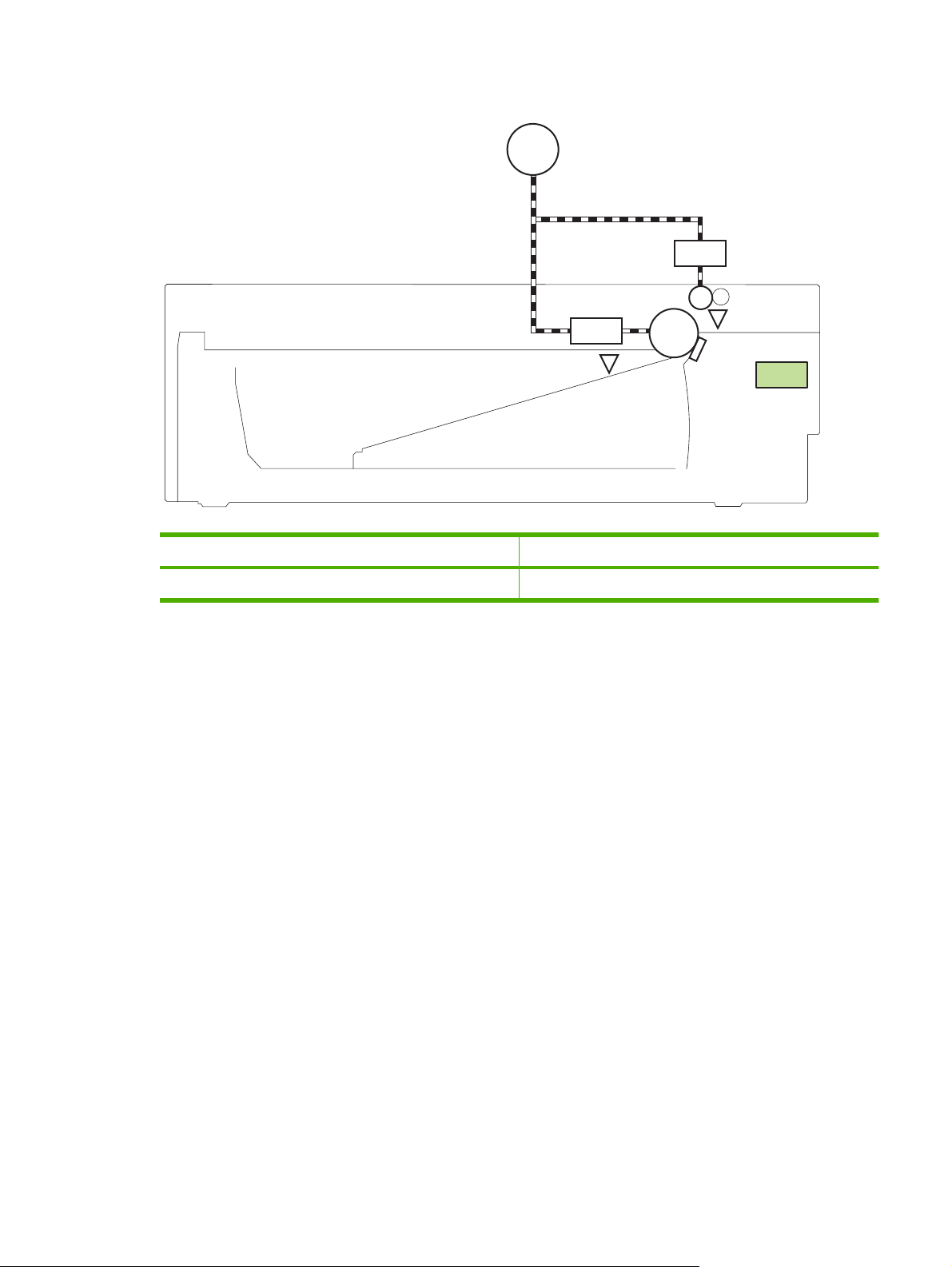
Figure 1-8 Switches (Tray 3 and Tray 4)
M8001
CL1
SL3
PS451
Table 1-7 Switches (Tray 3 and Tray 4)
Item Description
SW461 Paper feeder cassette presence switch
1
Tray 3 and Tray 4 are identical 500-sheet input trays.
PS8008
SW461
ENWW Engine-control s y ste m 11
Page 26
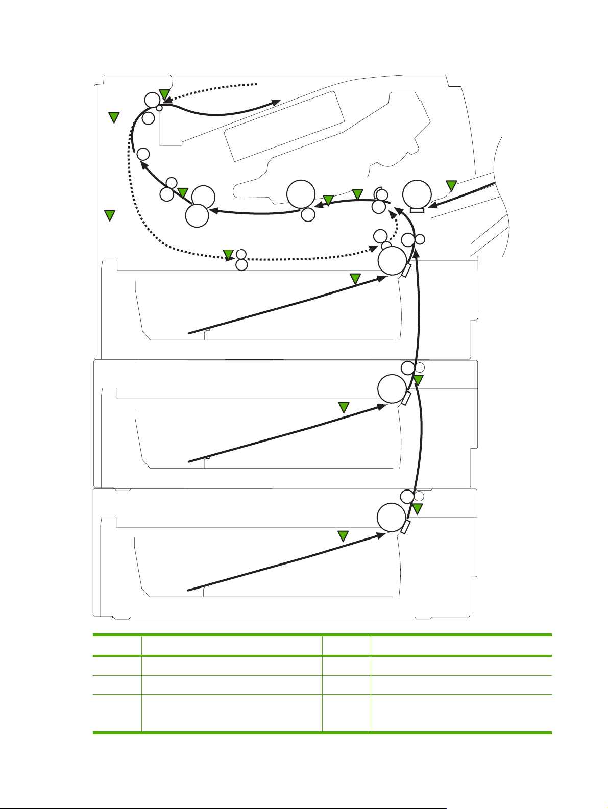
Figure 1-9 Sensors
PS4
PS1
PS8001
PS2
PS502
PS225
PS215
PS205
PS3
PS8008
PS451
PS8008
PS451
Table 1-8 Sensors
Item Description Item Description
PS1 Face-up sensor PS225 Media width sensor
PS2 Fuser delivery sensor PS502 Duplex media-feed sensor (duplex models only)
PS3 Cassette media-presence sensor PS451 Paper feeder cassette media-presence sensor
NOTE: PS451 is used in Tray 3, and Tray 4
12 Chapter 1 Theory of operation ENWW
Page 27

Table 1-8 Sensors (continued)
Item Description Item Description
PS4 Face-down tray media-full sensor PS8001 Rear door sensor
PS205 Tray 1 (multipurpose tray) media-presence
sensor
PS215 Top-of-Page (TOP) sensor
PS8008 Paper feeder media-feed sensor
NOTE: PS8008 is used in Tray 3, and Tray 4
ENWW Engine-control s y ste m 13
Page 28
DC controller operations
The DC controller controls the operational sequences of the product systems.
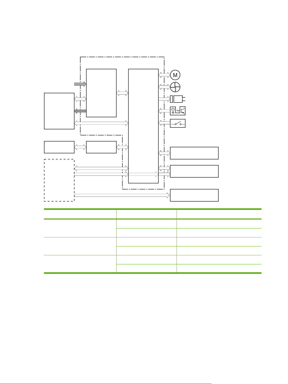
Figure 1-10 DC controller block diagram
Engine controller
Motor
AC input
Fuser
Print cartridge
Formatter
Low-voltage
power supply
High-voltage
power supply
DC controller
Fan
Solenoid
Photointerrupter
Switch
Optional paper-feeder
Laser/scanner
Control panel
Table 1-9 DC controller controlled components
Component Designator Description
Motor M8001 Main motor
M8002 Fuser motor
Fan FM1 Main fan
FM2 Sub fan
Solenoid SL1 Tray 1 (multipurpose tray) pickup solenoid
SL2 Cassette (Tray 2) pickup solenoid
14 Chapter 1 Theory of operation ENWW
Page 29

Table 1-9 DC controller controlled components (continued)
Component Designator Description
Photointerrupter PS1 Face-up sensor
PS2 Fuser delivery sensor
PS3 Cassette media presence sensor
PS4 Face-down tray (output bin) media-full sensor
PS205 Tray 1 (multipurpose tray) presen ce sensor
PS215 Top-Of-Page (TOP) sensor
PS225 Media width sensor
PS451 Paper feeder cassette media-presenc e sensor
NOTE: PS451 is used in Tray 3, and Tray 4
PS502 Duplex media-feed sensor (duplex models only)
PS8001 Rear door sensor
PS8008 Paper feeder media-feed sensor
Switch SW235 Cassette-presence switch
NOTE: PS8008 is used in Tray 3, and Tray 4
SW240 Power sw i tch
SW250 Test Print switch
SW501 Cartridge-door switch
ENWW Engine-control s y ste m 15
Page 30
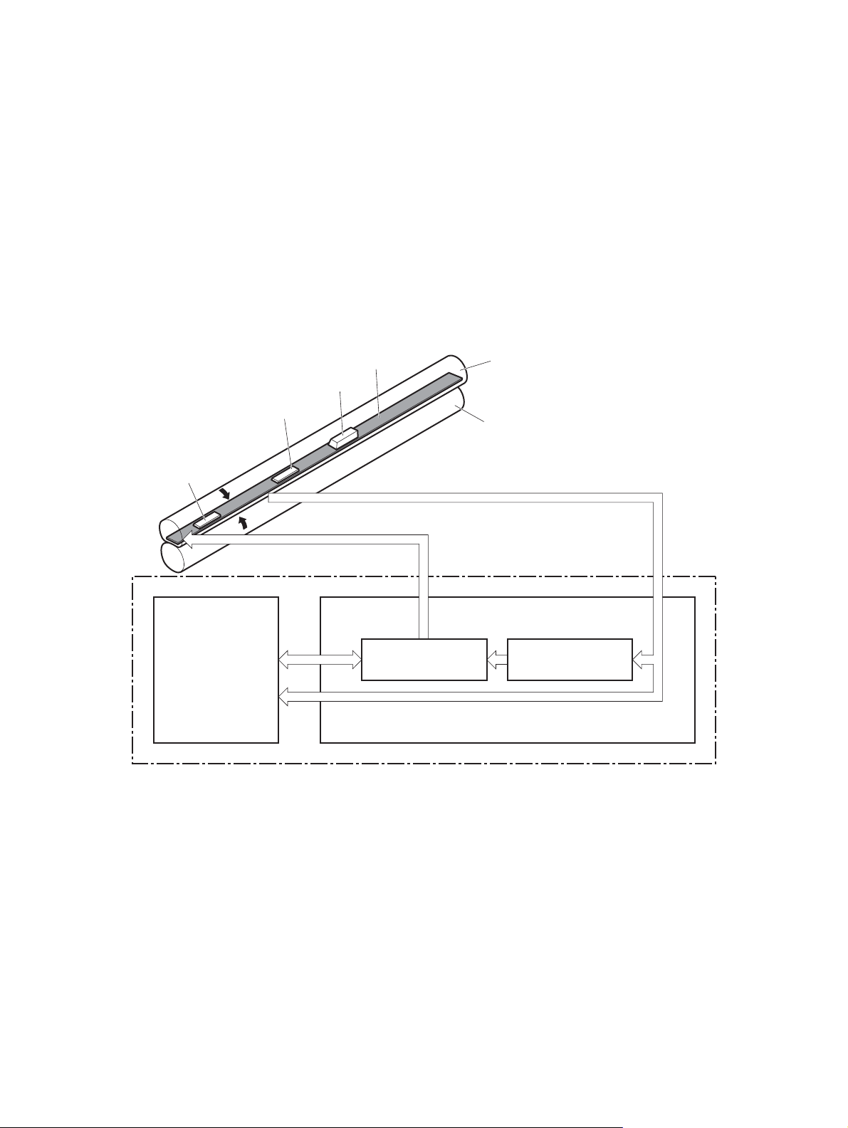
Fuser-control circuit
The fuser-control circui t moni tor s and control s the tem perature in the fuser. The product uses ondemand fusing. The fuser-contr ol ci r cuit consists of the following maj or com pon ents :
Fuser heater (H1); heats the fusing film
●
Thermistor (TH1 and TH2); detects the fuser tem per atu re (co ntact typ e)
●
Main thermistor (TH1); control s the tempe rat ur e in the fuser (c onta ct type)
◦
Sub thermistor (TH2); detects a one-sided temperature rise in the fuser and controls the
◦
temperature in the fuser (contact type)
Thermoswitch (TP1); preve nts abnorma l temperature rise in the fuser ( contac t typ e)
●
Figure 1-11 Fuser co nt r ol circuit
TP1
H1
Fuser film
TH2
DC controller
TH1
FUSER HEATER CONTROL signal
Fuser heater control
circuit
Engine controller unit
Pressure roller
FUSER TEMPERATURE signal
Fuser heater safety
circuit
Fuser control circuit
16 Chapter 1 Theory of operation ENWW
Page 31

Fuser failure detection
The DC controller determines a fuser unit failure, deactivates the FUSER HEATER CONTROL signal,
releases the relay to interrupt power supply to the fuser heater and notifies the formatter of a failure
state when it encounters the f oll owi ng condi tions:
Start-up failure
●
If the main thermistor does not detect a spec ifi ed tem per atu re during the start-up process of
◦
the heater in the wait period.
If the main thermistor does not detect a specified temperature during the heater temperature
◦
control in the initial rotati on peri od.
Abnormal low temperat ur e
●
If the main thermistor detects an abnormal low temperature of the fuser unit during the printing
◦
operation.
If the sub thermistor detects an abnormal low temperature of the fuser unit during the printing
◦
operation.
Abnormal high temperatu re
●
If the main thermistor detects an abn ormal high tem per atu re of the fuser uni t.
◦
If the sub thermistor detects an abno rm al hi gh temp er ature of the fus er unit .
◦
Frequency detection circ uit fa il ur e
●
If a specified frequency of the ZERO CROSSING signal is not detected within a specified
◦
period after the product is turne d on.
ENWW Engine-control s y ste m 17
Page 32

Fuser temperature control
The fuser temperature control maintains the temperature of the fuser heater at its targeted temperature.
The DC controller monitors the FUSER TEMPERATURE (FSRTH1, FSRTH2) signals and sends the
FUSER HEATER CONTROL (FSRD) signal according to the detected temperature. The fuser heater
control circuit controls the fuser heater depending on the signal so that the heater remains at the targeted
temperature.
Figure 1-12 Fuser-heater control circuit
Fuser control circuit
Engine controller unit
DC controller
RL1002
Fuser heater
control circuit
Fuser film
TP1
RL1001
TH2
TH1
Frequency
detection circuit
Relay control
circuit
Fuser heater
safety circuit
ZEROX
RLYD
FSRTH2
FSRTH1
FSRD
H1
Pressure roller
Fuser
H1: Fuser heater
TP1: Thermoswitch
TH1: Main thermistor
TH2: Sub thermistor
18 Chapter 1 Theory of operation ENWW
Page 33

Fuser protective function
The protective function detects an abnormal temperature rise of the fuser unit and interrupts power
supply to the fuser heater.
The following three protective components prevent an abnormal temperature rise of the fuser heater:
DC controller
●
The DC controller interrupts power supply to the fuser heater when it detects an abnormal
◦
temperature of the fuser heater.
Fuser heater safety cir cu it
●
The fuser heater safety circuit interrupts power supply to the fuser heater when the detected
◦
temperature of the main and sub thermistors is abnormal.
Thermoswitch
●
The contact of the thermoswitch is broken to interrupt power supply to the fuser heater when
◦
the thermoswitch detects an abnormal temperature of the fuser heater.
ENWW Engine-control s y ste m 19
Page 34

Low-voltage power supply
The low-voltage power supply (LVPS) converts ac input voltage to dc voltage. The LVPS has two fuses
on the PCA. The LVPS 24 V output is interrupted to the fuser and the high-voltage power supply if the
cartridge-door interlock switch (SW501) is in the off position (cover open).
WARNING! The product power switc h only inte rr upt s dc vo ltage from the LVPS. The ac voltage is
present in the product when the power cord is plugged into a power receptacle and the power switch is
in the off position. You must unplug the product power cord before servicing the product.
Figure 1-13 Low-voltage power supply (LVPS)
Fuse(FU1001)
Low-volt age power supply
Noise filter
Engine controller unit
Fuser control
circuit
Fuser
Noise filter
Protection
circuit
Fuse(FU1002)
+24V generation
circuit
REM24
+3.3V generation
circuit
+5V generation
circuit
+24V
+3.3V
/FDOORSNS
DC controller
Power-switch
control circuit
Power switch
(SW240)
High-voltage
power supply
+24R
Door switch
(SW501)
+24U
+3.3V
+5V
20 Chapter 1 Theory of operation ENWW
Page 35

Overcurrent/overvoltage protection
The low-voltage power supply has a protective function against overcurrent and overvoltage to prevent
failures in the power supply circuit. If an overcurrent or overvoltage condition occurs, the system
automatically cuts off the output voltage.
If the DC power is not being supplied from the low-voltage power supply, the protective function might
be running. In such case, turn off the power switch and unplug the power cord. Do not plug in the power
cord or turn on the power switch again until the cause is found.
WARNING! If you believe the overcurrent or overvoltage protection circuits have been activated, do
not plug in the product power cord or turn on the product power until the cause of the failure is found
and corrected.
In addition, two fuses in the low-voltage power supply protect against overcurrent. If overcurrent flows
into the AC line, the fuses melt and cut off the power distr ibuti on.
ENWW Engine-control s y ste m 21
Page 36

High-voltage power supply
The high-voltage power suppl y (HVPS) applies bia se s to the foll owi ng co mponents:
Primary charging roll er
●
Developing roller
●
Transfer rolle r
●
Fusing film
●
Figure 1-14 High-voltage power supply
Engine controller unit
DC controller
High-voltage power supply
Fuser film bias
charging bias
circuit
Primary
circuit
FSRB
FILMB
PRI
Fuser
Fuser film
Pressure roller
Cartridge
To primary charging roller
To developing roller
Developing
bias circuit
Transfer bias
circuit
DEV
Photosensitive drum
Transfer roller
TR
22 Chapter 1 Theory of operation ENWW
Page 37

Formatter
Formatter heartbeat LED
The heartbeat LED indicates that the formatter is functioning correctly. While the product is initializing
after you turn the product on, the LED blinks rapidly, and then turns off. When the product has finished
the initialization sequence, the heartbeat LED pulses on and off. For more information abut the heartbeat
LED see
DIMM slots
CAUTION: Single inline memory modules (SIMMs) used in previous HP LaserJet products are not
compatible with the product.
The formatter has one dual inline memory module (DIMM) slot for upgrading the product with more
memory.
To find out how much memory is installed in the product, print a configuration page. For more information
about memory, see
Formatter heartbeat LED on page 133.
DIMM cover and DIMM on page 57.
ENWW Engine-control s y ste m 23
Page 38

Laser/scanner system
The laser/scanner sy s tem receives VIDEO signal s fr om the EC U and t he formatter and converts the
signals into latent images on th e photosensitive drum.
The main components of the laser/scanner are the laser unit and the scanner motor unit. The DC
controller sends signals to the laser/scanner to control the functions of these components.
Figure 1-15 Laser/scanner sy st em
Engine controller unit
Formatter
DC controller
BDI signal
VIDEO signal
LASER CONTROL signal
SCANNER MOTOR CONTROL signal
Scanning mirror
BD sensor
Scanner motor unit
Photosensitive drum
Laser unit
24 Chapter 1 Theory of operation ENWW
Page 39

Laser failure detection
The DC controller determines an optical unit failure and notifies the formatter, if the laser/scanner
encounters the follo win g co ndi tio ns :
The scanner motor does not reach a specified rotation within a specified period of the scanner
●
motor start up.
The rotation of the scanner motor is out of specified range for a specified period during the scanner
●
motor drive.
The BD interval is out of a specified value during a print operation.
●
ENWW Engine-control s y ste m 25
Page 40

Image-formation sy stem
Electrophotographic process
The electrophotographic pro cess form s an ima ge on the pa per . Foll owin g ar e the ma jor co mpo nen ts
used in the process:
Print cartrid g e
●
Transfer rolle r
●
Fuser
●
Laser/scanner
●
The DC controller uses the laser/scanner and HVPS to form the toner image on the photosensitive drum.
The image is transferred to the print media and then fused onto the paper.
Figure 1-16 Electrophotographic process blo ck dia gra m
Laser scanner
Laser beam
Cartridge
Fuser
Transfer roller
High-voltage power supply
DC controller
Engine controller unit
26 Chapter 1 Theory of operation ENWW
Page 41

Image formation process
Each of the following process function independently and must be coordinated with the other product
processes. Image formation consists of the following processes:
Latent-image formation block
●
Step 1: primary chargin g
◦
Step 2: laser-beam ex pos ure
◦
Developing block
●
Step 3: developing
◦
Transfer block
●
Step 4: transfer
◦
Step 5: separation
◦
Fusing block
●
Step 6: fusing
◦
Drum cleaning block
●
Step 7: drum cleaning
◦
Figure 1-17 Image formation process
: Media path
: Direction of drum rotation
: Block
: Step
1. Primary charging
Delivery
Drum cleaning
6. Fusing (Fixing)
Fusing (Fixing)
7. Drum cleaning
Latent image formation
2. Laser-beam exposure
5. Separation
Transfer
3. Developing
4. T ransfer
Developing
Pickup
ENWW Image-formation system 27
Page 42

Latent-image formation stage
During the latent-image formation stage, the laser/scanner forms an invisible image on the
photosensitive drum in the pr int car t ri dge .
Primary charging
Step 1: DC and AC biases are applied to the primary charging roller, which transfers a uniform negative
potential to the photosensitive drum.
Figure 1-18 Primary ch ar gin g
Primary charging roller
Photosensitive drum
Laser beam exposure
Step 2: The laser beam scans the photosensitive drum to neutralize negative charges on parts of the
drum surface. An electrostatic latent image is formed on the drum where negative charges were
neutralized.
Figure 1-19 Laser beam exposure
Primary charging bias
Laser beam
Unexposed area Exposed area
28 Chapter 1 Theory of operation ENWW
Page 43

Developing stage
Print cartridge
Step 3: In the print cartridge, the developing cylinder comes in contact with the photosensitive drum to
deposit toner onto the electro sta tic late nt im age .
Figure 1-20 Print cartridge
Blade
Exposed area Unexposed area
Unexposed area
Toner acquires a negative charge from the friction that occurs when the developing roller rotatesagainst
the developing blade. The developing bias is applied to the developing roller to make a potential
difference between the developing roller and the photosensitive drum. The negatively charged toner is
attracted to the latent image on the photos ens it iv e dru m bec ause t he dru m surf a ce has a hig her
potential.
Developing roller
Photosensitive drum
Exposed area
Developing bias
ENWW Image-formation system 29
Page 44

Transfer stage
Step 4: The transfer charging roller, to which a DC positive bi as is appl ied , impa rts a positive charge
on the print media. When the print media comes in contact with the photosensitive drum, the toner is
transferred to the print media.
Figure 1-21 Transfer
Step 5: The elasticity of the print media causes its se parati on from the photosensitive drum. A s tati c
charge eliminator aid s se par ati on by weak en ing any el ec tro sta tic adhe si on.
Photosensitive
drum
Media
Transfer roller
Transfer bias
Figure 1-22 Separation
Static charge eliminator
Fusing stage
Step 6: The DC negative bias applied to the fusing film strengthens the holding force of the toner on the
print media and prevents the toner fr om s catter ing .
Photosensitive
drum
Media
Transfer roller
30 Chapter 1 Theory of operation ENWW
Page 45

The product uses an on-demand fuser method. The toner image is permanently affixed to the printing
paper by heat and pressure.
Figure 1-23 Fusing
Cleaning stage
Fuser heater
Brush
Fuser film
Toner
Media
Pressure roller
Fuser bias
Step 7: The cleaning blade scrapes the residual toner off of the photosensitive drum and deposits it into
the waste toner case.
Figure 1-24 Drum cleaning
Cleaning blade
Toner collection box
Photosensitive
drum
ENWW Image-formation system 31
Page 46

Toner detection
The product uses a nonvolati le memo ry tag bui lt in to the prin t car tr id ge. Pr i nt- ca rtr id ge det ec tion
happens when the engine controller detects the presence of a genuine HP print-cartridge that contains
a memory tag. Toner detection happens as the engine controller reads or writes the data that is stored
on the memory tag. The engine controller renews the information in the prescribed timing and reads or
writes it from or to the memory tag.
The engine controller commands the memory tag to read or write with the fol lo wing con diti ons :
Read
●
Power is on
◦
The cartridge door is cl os ed
◦
A command is received from the formatter
◦
Write
●
A page of media is printed
◦
A command is received from the formatter
◦
When the engine controller fails to read or write three times in a row, it determines that the memory tag
is abnormal and sends a cartridge memory abnormality warning to the formatter.
Figure 1-25 Print cartridge memory tag
32 Chapter 1 Theory of operation ENWW
Page 47

Pickup, feed, and delivery system
The pickup/feed/deliv er y system cons is ts of se ver al types of feed rol lers and sensors. The ECU uses
a motor and two solenoids to drive the rollers. Three media-detection sensors detect paper as it passes
through the product. If media does not reach or pass each sensor within a specified time, the ECU
determines that a jam has occurr ed and aler ts the form atte r.
Paper trays
The product has the following paper trays:
Tray 1 (multipurpose tray; all models)
●
Tray 2 (500-sheet tray; all model s)
●
Tray 3 (optional 500-sheet input tray; HP LaserJet P3015x)
●
Tray 4 (optional 500-sheet in put tr ay )
●
ENWW Pickup, feed, and delivery system 33
Page 48

Photo sensors and switches
Figure 1-26 Photo sensors and switches (product)
PS4
PS1
M8001
SW501
PS8001
M8002
PS2
PS502
PS225
SL2
PS215
PS3
SL1
PS205
SW235
Table 1-10 Photo sensors and switches (product)
Item Description Item Description
PS1 Face-up sensor PS215 Top-of-Page (TOP) sensor
PS2 Fuser delivery sensor PS225 Media width sensor
PS3 Cassette media-presence sensor PS502 Duplex media-feed sensor (duplex models only)
PS4 Face-down tray media-full sensor PS8001 Rear door sensor
PS205 Tray 1 (MP tray) media-presence sensor SW235 Cassette presence sensor
34 Chapter 1 Theory of operation ENWW
Page 49

Figure 1-27 Photo sensors and switches (Tray 3 and Tray 4)
M8001
CL1
SL3
PS451
PS8008
SW461
Table 1-11 Photo sensors and switches (Tray 3 and Tray 4)
Item Description
PS451 Paper feeder cassette-media presence sensor
PS8008 Paper feeder media-feed sensor
SW461 Paper feeder cassette presence switch
1
Tray 3 and Tray 4 are identical 500-sheet input trays.
ENWW Pickup, feed, and delivery system 35
Page 50

Solenoids and clutches
Figure 1-28 Solenoids and clu tch es ( pr odu ct)
PS4
PS1
M8001
SW501
PS8001
M8002
PS2
PS502
PS225
SL2
PS215
PS3
SL1
PS205
SW235
Table 1-12 Solenoids and clutches (product)
Item Description
SL1 Tray 1 (multipurpose tray) pickup solenoid
SL2 Cassette (Tray 2) pickup solenoid
36 Chapter 1 Theory of operation ENWW
Page 51

Figure 1-29 Solenoids and clutches (Tr ay 3 and T ray 4)
M8001
CL1
SL3
PS451
Table 1-13 Solenoids and clutches (Tray 3 and Tray 4)
Item Description
SL3 Paper feeder pickup solenoid
CL1 Paper feeder pickup clutch
1
Tray 3 and Tray 4 are identical 500-sheet input trays.
PS8008
SW461
ENWW Pickup, feed, and delivery system 37
Page 52

Tray 1 or Tray 2
Pickup and feed unit
The pickup and feed unit uses the following components and processes.
Cassette pape r size detectio n/cassette pap er detection
NOTE: To find the following components, see Photo sensors and s witc he s on page 34.
PS3; cassette media-pres enc e s ens or
●
PS225; media width sensor (detects media width after the media enters the paper path)
●
Cassette pickup
NOTE: To find the following components, see Solenoids and clutches on page 36.
SL2; cassette (Tray 2) pickup solenoid
●
Tray 1 paper pickup
NOTE: To find the following components, see Photo sensors and switches on page 34 and Solenoids
and clutches on page 36.
PS205; Tray 1 (multipurpose tray) media-presence sensor
●
SL1; Tray 1 (multipurpose tray) pic k up so len oid
●
38 Chapter 1 Theory of operation ENWW
Page 53

Paper pickup and feed
The following figure shows the pickup and feed paper path.
NOTE: Duplex models include a duplex media-feed path for automatic two-sided printing.
Figure 1-30 Pickup, feed, and delivery bloc k di agr am
Delivery roller
Fuser film
Pressure roller
Simplex media path
Duplex media path
Photosensitive drum
Transfer roller
Cassette pickup roller
MP tray pickup roller
MP tray separation pad
Cassette separation pad
ENWW Tray 1 or Tray 2 39
Page 54

Jam detection
The product uses the following sensors to detect the presence of media and to check for jams. If media
does not reach or pass each sensor within a specified time, the ECU determines that a jam has occurred
and alerts the formatter.
NOTE: To find the following components, see Photo sensors and s witc he s on page 34.
PS2; fuser deli ve ry sensor
●
PS4; face-down tray media-fu ll s ensor
●
PS215; Top-of-Pag e (TO P) se ns or
●
PS225; media width sensor
●
PS502; duplex media-feed sensor (duplex model s only)
●
PS8008; paper feeder media- fe ed se ns or
●
NOTE: PS8008 is used in Tray 3 and Tray 4.
The product detects the follo wing jams:
Pickup delay jam
●
Pickup stationary jam
●
Delivery delay jam
●
Delivery stat io nar y jam
●
Fuser wrapping jam
●
Door open jam
●
Residual media jam
●
Duplex repickup jam (duplex models only)
●
40 Chapter 1 Theory of operation ENWW
Page 55

Additional tray
NOTE: This product supports identical 500-sheet input trays ( Tray 3 and Tra y 4).
Tray driver PCA
The following figure shows the signals between the DC controller and the tray driver PCA.
Figure 1-31 Tray 3 and Tray 4 driver PCA block diagram
Optional paper feeder
Clutch
DC controller
+24V
Paper feeder
Solenoid
connector PCB
Photointerrupter
Switch
ENWW Additional tray 41
Page 56

Paper pickup and feed
NOTE: Tray 3 and Tray 4 are identical 500-sheet input trays.
The following figure shows the pickup and feed paper path (Tray 3 shown).
Figure 1-32 Tray 3 and Tray 4 pickup, feed, and delivery block diagram
Optional paper feeder
separation pad
Optional paper feeder
pickup roller
Optional paper feeder
feed roller
42 Chapter 1 Theory of operation ENWW
Page 57

Media level and size detection
PS451; paper feeder media -pres en ce se ns or detec ts if med ia is pre sent in the tray.
●
NOTE: PS451 is used in Tray 3 and Tray 4.
Media size is detected after the page enters the product. See
●
cassette paper detection on page 38.
Jam detection
PS8008; paper feeder media-feed sensor detects jams in the paper feeder.
●
Cassette paper siz e dete cti on/
ENWW Additional tray 43
Page 58

44 Chapter 1 Theory of operation ENWW
Page 59

2 Removal and replacement
Removal and replacement st ra teg y
●
Service approach
●
Removal and replacement p roced ur es
●
ENWW 45
Page 60

Removal and replacement strategy
General cautions during removal and replacement
This chapter describes the removal and replace men t of fiel d- replaceable units (FR Us) onl y.
Replacing FRUs is generally the reverse of removal. Occasionally, notes and tips are included to provide
directions for diffic ult or critical replacement procedures.
HP does not support repairing individual subassemblies or troubleshooting to the component level.
WARNING! Turn the product off, wait 5 seconds, and then remove the power cord before attempting
to service the product. If this warning is not followed, severe injury can result, in addition to damage to
the product. The power must be on for certain functional checks during troubleshooting. However,
disconnect the power supp ly during parts removal.
Never operate or serv ic e the pr odu ct with the protective cove r r emo ved f rom the la ser /s ca nne r
assembly. The reflected beam, although invisible, can damag e you r eyes .
The sheet-metal parts can have sharp edges. Be careful when handling sheet-metal parts.
CAUTION: Do not bend or fold the flat flexible cables (FFCs) during removal or installation. Also, do
not straighten prefolds in the FFCs. You must fully seat all FFCs in their connectors. Failure to fully seat
an FFC into a connector can cause a short circuit in a PCA.
Incorrectly routed or loose wire harnesses can interfere with other internal components and can become
damaged or broken. Frayed or pi nch ed har ne ss wire s ca n be diffi cult to find. When replacing wi re
harnesses, always use the prov id ed wir e lo ops , lan ce poin ts, or wir e-har ne ss guides and retainers.
NOTE: To install a self-tapping screw, first turn it counterclockwise to align it with the thread pattern,
and then carefully turn it clockwise to tighten. Do not overtighten. If a self-tapping screw-hole becomes
stripped, repair the screw -ho le or replace the affected assembly.
Note the length, diameter, color, type, and location of each screw. Be sure to return each screw to its
original locatio n du ri ng r eas se mbly.
TIP: For clarity, some photos in this chapter might show components removed that would not be
removed to service the product. If necessary, remove the components listed at the beginning of a
procedure before proceeding to service the product.
Electrostatic discharge
CAUTION: Some parts are sensitive to electrostatic discharge (ESD). Look for the ESD reminder
when removing product parts. Always perform service work at an ESD-protected workstation or mat, or
use an ESD strap. If an ESD workstation, mat, or strap is not available, ground yourself by touching the
sheet-metal ch as sis before touching an ESD- se ns iti ve pa rt.
Protect the ESD-sensitive parts by placing them in ESD pouches when they are out of the product.
Required tools
#2 Phillips 152 mm (6 in) screwdriver with magnetic tip
●
#2 Phillips 76 mm (3 in) screwdriver with magnetic tip
●
Small flat blade screwdriver
●
46 Chapter 2 Removal and replacement ENWW
Page 61

Small needle-nose pli e rs
●
ESD mat
●
Penlight
●
CAUTION: Always use a Phillips screwdriver (callout 1). Do not use a pozidrive screwdriver (callout 2)
or any motorized screwdriver. These can damage screws or scre w threads.
Figure 2-1 Phillips and pozidr iv e s cr ewd ri ver comparison
Types of screws
NOTE: The illustration in this section are for referenc e onl y. The screw s in your product might look
slightly different.
Illustration Description Size Part number Use
Screw with washer M3X6 XB2-7300-000CN Used to secure metal
components to metal
components (for
example, a ground wire
to the frame)
Screw, tapping M3X6 XA9-1503-000CN
Screw D-M3X6 XA9-1671-000CN
Screw P-M3X8 XB4-5300-807CN
Screw, tapping, truss
head
M4X10 XB4-7401-005CN Used to secure
anything to plastic
ENWW Removal and replacement s tra tegy 4 7
Page 62

Service approach
Product repair normally begins by using the product internal diagnostics and the following two-step
process:
1. Isolate the problem to the major system (for example, the network or server, or the product).
2. Trou bleshoot the problem by using the procedures in chapter 6.
After you find a faulty part, the product can usually be repaired at the assembly level by replacing fieldreplaceable units (FRUs). Some mechanical assemblies might need to be repaired at the subassembly
level.
Before performing service
Remove all media from the product.
●
Turn off the power using the power switch.
●
Unplug the power cable and interface cable or cables.
●
Place the product on an ESD workstation or mat, or use an ESD strap (if one is available). If an
●
ESD workstation, mat, or strap is not available, ground yourself by touching the sheet-metal chassis
before touching an ESD-sensitive part.
Remove the print cartridges. See
●
Remove the tray cassette or cassettes. See
●
on page 54.
After performing service
Plug in the power cable.
●
Reinstall the print cartridges.
●
Reinstall the tray cassette or cassettes.
●
If an optional paper feeder was installed, place the product on the feeder.
●
Post-service test
Perform the following test to verify that the repair or replacement was successful.
Print-quality test
1. Ver if y that yo u ha ve com pl eted the nec es sary reassembly step s.
2. Make sure that the tray contains clean, unmarked paper.
3. Attach the power cord and interface cable or interface cables, and then turn on the product.
Print cartridge on page 52.
Tray cassette (Tray 2, Tray 3, or Tray 4)
4. Verify that the expected start-up sounds occur.
5. Print a configuration page, and then verify that the expected printing sounds occur.
6. Print a demo page, and then verify that the print quality is as expected.
48 Chapter 2 Removal and replacement ENWW
Page 63

7. Send a print job from the host computer, and then verify that the output meets expectations.
8. If nec es sa ry , res to re an y c ust ome r-s pec ifi ed s etti ngs .
9. Clean the outside of the product with a damp cloth.
ENWW Service approach 49
Page 64

Parts removal order
Figure 2-2 Parts removal order (1 of 2)
Component
Print cartridges
Tray cassette (Tray 2, Tray 3, or Tray 4)
Sub cover
DIMM cover and DIMM
Formatter cover and formatter PCA
Rear-door assembly
Left Cover
Right-rear cover
Tray 1 (multipurpose tray) cover
Cartridge door assembly
Top-right cover
Control panel
Front-right and right-side cover assembly
Lower-right cover and bracket
Top cover
Tray 1 (multipurpose tray) pickup roller
Tray 1 (multipurpose tray) separation pad
Tray 2, Tray 3, or Tray 4 pickup roller
Tray 2, Tray 3, or Tray 4 separation pad
Tray 2, Tray 3, or Tray 4 base-plate roller assembly
Transfer roller
USB port PCA
Power-switch assembly
Main Fan, fan duct, and environmental sensor
Fuser
Registration assembly
Duplex media-feed guide
Laser/scanner assembly
Engine control unit (ECU)
Cassette pickup (Tray 2) solenoid
or Tray 1 (multipurpose tray) pickup solenoid
Remove Remove Remove Remove Remove
DIMM cover
Rear-door assembly
Rear-door assembly
Rear-door assembly
DIMM cover
DIMM cover
DIMM cover
DIMM cover
DIMM cover
DIMM cover
DIMM cover
DIMM cover
Rear-door assembly
Rear-door assembly
Rear-door assembly
DIMM cover
DIMM cover
DIMM cover
Left Cover
Left Cover
Formatter cover
Formatter cover
Formatter cover
Formatter cover
Formatter cover
Formatter cover
Formatter cover
Formatter cover
Right-rear cover
Left Cover
Right-rear cover
Formatter cover
Formatter cover
Formatter cover
Tray 1 cover
Top-cover assembly
Control panel
Rear-door assembly
Top-right cover
Top-right cover
Top-right cover
Rear-door assembly
Rear-door assembly
Rear-door assembly
Front-right
and right-side
cover assembly
Left Cover
Control panel
Control panel
Control panel
Left Cover
Left Cover
Left Cover
Top-right cover
Front-right
and right-side
cover assembly
Front-right
and right-side
cover assembly
Front-right
and right-side
cover assembly
Top-right cover
Top-right cover
Top-right cover
Remove
Control panel
Control panel
Control panel
Control panel
Pickup assembly
Fuser motor
Sub fan and fan duct
High-voltage power supply
DIMM cover
DIMM cover
DIMM cover
DIMM cover
Formatter cover
Formatter cover
Formatter cover
Formatter cover
Rear-door assembly
Rear-door assembly
Rear-door assembly
Rear-door assembly
Left Cover
Left Cover
Left Cover
Left Cover
Top-right cover
Top-right cover
Top-right cover
Top-right cover
Control panel
Control panel
Control panel
Control panel
50 Chapter 2 Removal and replacement ENWW
Page 65

Figure 2-3 Parts removal order (2 of 2)
Remove Remove Remove Remove
Top cover
Front-right
and right-side
cover assembly
Front-right
and right-side
cover assembly
Front-right
and right-side
cover assembly
Front-right
and right-side
cover assembly
Front-right
and right-side
cover assembly
Front-right
and right-side
cover assembly
Lower-right
cover and bracket
Lower-right
cover and bracket
Lower-right
cover and bracket
Lower-right
cover and bracket
Lower-right
cover and bracket
Lower-right
cover and bracket
Top cover
Top cover
Top cover
Top cover
Top cover
Top cover
Power-switch
assembly
Power-switch
assembly
Power-switch
assembly
Power-switch
assembly
Power-switch
assembly
Power-switch
assembly
Remove Remove
Engine control
unit (ECU)
Engine control
unit (ECU)
Engine control
unit (ECU)
Engine control
unit (ECU)
Duplex
media-feed
guide (duplex
models only)
Engine control
unit (ECU)
Remove
Sub fan and fan duct
ENWW Service approach 51
Page 66

Removal and replacement procedures
Print cartridge, cassettes, and sub cover
Print cartridge
CAUTION: If toner gets on your clothing, wipe it off with a dry cloth and wash clothing in cold water.
Hot water sets toner into fabric.
1. Press the cartridge-door release button, and then open the cartridge door. Make sure that the door
is completely open.
Figure 2-4 Remove the print cartridge (1 of 2)
52 Chapter 2 Removal and replacement ENWW
Page 67

2. Gras p the pr int -car tr idg e handl e and pul l it out of th e pro duc t.
CAUTION: Do not touch the green roller. Doing so can damage the cartridge. Do not expose the
cartridge to strong light. Cover the cartridge with a sheet of paper to protect it from light.
Reinstallation tip Align the print cartridge with its slot and insert the print cartridge until it clicks
into place.
Figure 2-5 Remove the print cartridge (2 of 2)
ENWW Removal and replace me nt pr oc edu res 53
Page 68

Tray cassette (Tray 2, Tray 3, or Tray 4)
NOTE: Use this procedure to remove the Tray 2 or optional Tray 3 or Tray 4 cassette.
1. Pull the tray straight out of the product until it stops.
Figure 2-6 Remove the tray cassette (1 of 2)
2. Car efu lly lift up on the tray to re lease it, and then remove the tray.
Figure 2-7 Remove the tray cassette (2 of 2)
54 Chapter 2 Removal and replacement ENWW
Page 69

Sub cover
NOTE: Duplex models only. The space under the sub cover is used by third-party manufacturers to
install optio nal devices for this product (for example, a security card reader).
Use a small flat blade screwdriver to carefully separate the sub cover from the product.
CAUTION: There are two tabs along the each of the long edges of the cover that fasten the cover to
the product. Do not breack the tabs when the cover is removed.
Figure 2-8 Remove the sub cover
ENWW Removal and replace me nt pr oc edu res 55
Page 70

External panels, covers, doors, formatter PCA, DIMM, and EIO disk
EIO disk
WARNING! ESD sensitive component.
1. Loosen two thumb screws (callout 1).
Figure 2-9 Remove the EIO disk (1 of 2)
1
2. Pul l the EIO disk str ai ght out of the produ ct to re mov e it.
Figure 2-10 Remove the EIO disk (2 of 2)
56 Chapter 2 Removal and replacement ENWW
Page 71

DIMM cover and D IMM
WARNING! ESD sensitive component.
1. Slide the DIMM cover toward the back of the product to release it.
Figure 2-11 Remove the DIMM cover and DIMM (1 of 3)
2. Lift the cover away from the product.
Figure 2-12 Remove the DIMM cover and DIMM (2 of 3)
ENWW Removal and replace me nt pr oc edu res 57
Page 72

3. Release two tabs (callout 1) and rotate the top of the DIMM away from the formatter. Lift up on the
DIMM to remove it.
Figure 2-13 Remove the DIMM cover and DIMM (3 of 3)
Reinstal l the DIMM
1. Position the DIMM at an angle to the DIMM slot, and rotate the top of the DIMM toward the formatter.
1
XO
XO
XOXO
XO
XO
XO
O
XO
XOXOXO
XOX
XOXOXO
XO
XO
XO
O
O
O
XO
X
XO
X
XO
O
XOX
XOX
XOXO
XOXO
XOX
O
XO
O
X
XO
XO
XO
XO
XO
XO
XO
XOXO
XO
XO
XO
O
XO
O
X
X
XO
XO
O
OXIX
O
XIX
O
O
XIX
O
O
XI
O
XIX
XI
O
XI
O
XI
XIO
O
XI
XIO
O
XI
XO
XIXO
O
O
XIX
O
O
OXIX
I
O
XIX
XIOX
O
XI
O
I
X
XIOXIO
OXIO
XI
XO
XO
XO
Figure 2-14 Reinstall the DIMM (1 of 2)
58 Chapter 2 Removal and replacement ENWW
Page 73

2. Pu sh down to seat it in the DIMM slot. The DIMM must snap into the locking tabs on the DIM M
slot.
Figure 2-15 Reinstall the DIMM (2 of 2)
ENWW Removal and replace me nt pr oc edu res 59
Page 74

Formatter cover and formatter PCA
WARNING! ESD sensitive component.
1. Remove the DIMM cover. See DIMM cover and DIMM on page 57.
2. Remove one screw (callout 1), and then slide the formatter cover toward the back of the product
to release it.
Figure 2-16 Remove the formatter cover and formatter PCA (1 of 4)
1
3. Lift the cover away from the product.
Figure 2-17 Remove the formatter cover and formatter PCA (2 of 4)
60 Chapter 2 Removal and replacement ENWW
Page 75

4. Dis c onne ct thr ee conne ctors (callout 1; J14, J17, and J16) and one FFC (c al lou t 2; J1 8).
Figure 2-18 Remove the formatter cover and formatter PCA (3 of 4)
2
1
5. Remove seven screws (callout 1), and then carefully remove the formatter PCA.
Figure 2-19 Remove the formatter cover and formatter PCA (4 of 4)
1
ENWW Removal and replace me nt pr oc edu res 61
Page 76

Rear-door assembly
1. Op en the re ar door .
Figure 2-20 Remove the rear-door assembly (1 of 8)
2. Gently pull down on the door and lower the door until it is fully open.
Figure 2-21 Remove the rear-door assembly (2 of 8)
62 Chapter 2 Removal and replacement ENWW
Page 77

3. Pu sh up on the li nk ar m to rel eas e it.
CAUTION: The link arm is under spring tension. Do not let the link arm snap back toward the
product when you release it.
Figure 2-22 Remove the rear-door assembly (3 of 8)
4. Remove two screws (callout 1).
Figure 2-23 Remove the rear-door assembly (4 of 8)
1
ENWW Removal and replace me nt pr oc edu res 63
Page 78

5. Op en the low er -rea r door, and then releas e one ta b (call out 1).
Figure 2-24 Remove the rear-door assembly (5 of 8)
1
6. Rel eas e one tab (c al lo ut 1) .
Figure 2-25 Remove the rear-door assembly (6 of 8)
1
64 Chapter 2 Removal and replacement ENWW
Page 79

7. Rota te the bottom of the rear-door assembly away fr om the pr odu ct.
Figure 2-26 Remove the rear-door assembly (7 of 8)
8. Pu ll down on the rear-door asse mbl y to re mov e it.
Figure 2-27 Remove the rear-door assembly (8 of 8)
ENWW Removal and replace me nt pr oc edu res 65
Page 80

Left cover
1. Remove the rear-door assembly. See Rear-door assembly on page 62.
2. Remove one screw (callout 1).
Figure 2-28 Remove the left cover (1 of 4)
1
3. Release three tabs (callout 1).
TIP: The tab inside the cassette cavity is located below the plastic cassette rail. It might be easier
if slightly lift up the left side of the product, and use a small flat blade screwdriver to release this
tab.
Figure 2-29 Remove the left cover (2 of 4)
1
66 Chapter 2 Removal and replacement ENWW
Page 81

4. Rel eas e one tab (callo ut 1) .
Figure 2-30 Remove the left cover (3 of 4)
1
5. Rotate the rear of the cover slightly away from the product, and then slide the cover toward the
front of the product to remove it.
Figure 2-31 Remove the left cover (4 of 4)
ENWW Removal and replace me nt pr oc edu res 67
Page 82

Right-rear cover
1. Remove the rear-door assembly. See Rear-door assembly on page 62.
2. Sl ide the right-rear cover towa rd the inside of the product to releas e it.
Figure 2-32 Remove the right-rear cover (1 of 2)
3. Rotate the bottom of the cover away from the product, and then pull down on the cover to remove
it.
Figure 2-33 Remove the right-rear cover (2 of 2)
68 Chapter 2 Removal and replacement ENWW
Page 83

Tray 1 (multipurpose tray) cover
1. Be for e pro cee ding, remove the followi ng components:
Rear-door assembly. See
●
Left cover. See
●
2. Car efu lly releas e two r etai ni ng ar ms (c all out 1).
Figure 2-34 Remove Tray 1 cover (1 of 3)
Left cover on page 66.
Rear-door assembly on page 62.
1
3. Sl igh t ly lower the co ver , and the n sli de it towa rd the left si de of the pro duct.
TIP: If you lower the tray too far, it will not slide off of the hinge pins.
Figure 2-35 Remove Tray 1 cover (2 of 3)
ENWW Removal and replace me nt pr oc edu res 69
Page 84

4. Remove the Tray 1 cover.
Figure 2-36 Remove Tray 1 cover (3 of 3)
70 Chapter 2 Removal and replacement ENWW
Page 85

Cartridge-door assembly
1. Be for e pro cee ding, remove the followi ng components:
Rear-door assembly. See
●
Left cover. See
●
Tray 1 (multipurpose tray ) co ve r. See
●
TIP: The cartridge-door as sem bl y ca n be rem ove d w ith out r emo vi ng the Tr ay 1 cover.
However, it is easier to remove and reinstall the door assembly when the Tray 1 cover is not
installed.
2. Remove one spring (callout 1).
Figure 2-37 Remove the cartridge- do or asse mbl y (1 of 3)
Left cover on page 66.
Rear-door assembly on page 62.
Tray 1 (multipurpose tray) cover on page 69.
1
ENWW Removal and replace me nt pr oc edu res 71
Page 86

3. Slightly slide the assembly toward the left side of the product to release it from the hinge pins.
CAUTION: Do not damage the plastic link arm (callout 1).
Figure 2-38 Remove the cartr id ge- doo r as se mbl y (2 of 3)
1
4. Rotate the assembly down, and then separate the plastic link arm (callout 1) from the assembly.
Remove the cartridge-door assembly.
Figure 2-39 Remove the cartr id ge- doo r as se mbl y (3 of 3)
1
72 Chapter 2 Removal and replacement ENWW
Page 87

Top-right cover
1. Be for e pro cee ding, remove the followi ng components:
DIMM cover. See
●
Formatter cover. See
●
2. Remove two screws (callout 1).
Figure 2-40 Remove the top-right cover (1 of 2)
DIMM cover and DIMM on page 57.
Formatter cover and formatter PCA on page 60.
1
3. Lift the cover off of the product to remove it.
Figure 2-41 Remove the top-right cover (2 of 2)
ENWW Removal and replace me nt pr oc edu res 73
Page 88

Control panel
WARNING! ESD sensitive component.
1. Before proceeding, remov e the foll owi ng components:
DIMM cover. See
●
Formatter cover. See
●
2. Press the cartridge-door release button, and then open the cartridge door. Make sure that the door
is completely open.
Figure 2-42 Remove the control panel (1 of 4)
DIMM cover and DIMM on page 57.
Formatter cover and formatter PCA on page 60.
3. Dis co nne ct one conne ct or (c al lou t 1), and then remove one screw (callout 2).
Figure 2-43 Remove the control panel (2 of 4)
1
2
74 Chapter 2 Removal and replacement ENWW
Page 89

4. Sl ide the cont rol panel towar d the front of the pr oduc t to releas e it.
Figure 2-44 Remove the control panel (3 of 4)
5. Lift the control panel off of the product.
Figure 2-45 Remove the control panel (4 of 4)
ENWW Removal and replace me nt pr oc edu res 75
Page 90

Front-right and right-side cover assembly
1. Before proceeding, remov e the foll owi ng components:
DIMM cover. See
●
Formatter cover. See
●
Cartridge-door asse mbl y. See
●
NOTE: The figures in this section show the cartridge-door assembly installed. However, it
might be easier to reinstal l the fr ont -r ig ht and right-side cover as se mbly if the cartridge-doo r
assembly is removed.
Control panel. See
●
2. Remove two screws (callout 1).
Figure 2-46 Remove the front-right and right-side cover assembly (1 of 6)
DIMM cover and DIMM on page 57.
Formatter cover and formatter PCA on page 60.
Cartridge-door ass emb ly on page 71.
Control panel on page 74.
1
76 Chapter 2 Removal and replacement ENWW
Page 91

3. Disconnect one connector (callout 1; J14), release the wire harness from the guide (callout 2), and
then remove two screws (callout 3).
Figure 2-47 Remove the front-right and rig ht- si de co ve r ass em bl y (2 of 6)
3
2
4. Slightly push the cover assembly toward the front of the product to release it, and then carefully
rotate the cover away from the product.
1
CAUTION: Do not damage the covers or the cartridge-door assembly (if you did not remove it)
when you rotate the cover assembly away from the product.
Do not dislodge the power-switch assembly (callout 1) when you rotate the cover assembly away
from the product.
Figure 2-48 Remove the front-right and rig ht- si de co ve r ass em bl y (3 of 6)
1
ENWW Removal and replace me nt pr oc edu res 77
Page 92

5. R em ove the cover assembly .
Reinstallation tip The figur es in this sec ti on sh ow the car tr idg e- door assem bl y in sta lled.
However, it might be easier to reinstall the front-right and right-side cover assembly if the cartridgedoor assembly is removed. See
Figure 2-49 Remove the front-right and right-side cover assembly (4 of 6)
Cartridge-door ass emb ly on page 71.
6. If necessary, remove two screws (callout 1), release two tabs (callout 2), and then slide the front-
right cover toward the top of the right-side cover to release it.
Figure 2-50 Remove the front-right and right-side cover assembly (5 of 6)
1
2
78 Chapter 2 Removal and replacement ENWW
Page 93

7. If necessary, separate the front-right cover from the right-side cover.
Figure 2-51 Remove the front-right and rig ht- si de co ve r ass em bl y (6 of 6)
ENWW Removal and replace me nt pr oc edu res 79
Page 94

Lower-right cover and bracket
NOTE: You do not need to remove the sheet-metal bracket to remove the lower-right cover. However,
you must remove the bracket and the cover when removing some of the other product components in
this chapter. Use this procedure to remove the cover only, or the cover and the bracket.
1. Before proceeding, remov e the foll owi ng components:
DIMM cover. See
●
Formatter cover and Formatter PCA. See
●
Top-right cover. See
●
Control panel. See
●
Front-right and right-side cover assembly. See
●
on page 76.
2. To remove the cover and the bracket: Remove three screws (callout 1).
To remove the bracket only: Remove one screw (the bottom most screw in callout 1).
Figure 2-52 Remove the lower-right cover (1 of 4)
DIMM cover and DIMM on page 57.
Formatter cover and formatter PCA on page 60.
Top-right cover on page 73.
Control panel on page 74.
Front-right and right-s id e cover assembly
1
80 Chapter 2 Removal and replacement ENWW
Page 95

3. To remove the bracket only:: Slide the sheet-metal bracket up to release it, and then remove the
bracket.
NOTE: You might need to slightly pull outward on the lower-right cover (callout 1) to release the
sheet-metal bracket.
Reinstallation tip When you reinstall the bracket, make sure that the tab (callout 2) is engaged
in the slot in the chassis.
Figure 2-53 Remove the lower-right cover (2 of 4)
2
1
4. Raise the right side of the product, slide the lower-right cover toward the back of the product, and
then rotate the cover away from the product.
Figure 2-54 Remove the lower-right cover (3 of 4)
ENWW Removal and replace me nt pr oc edu res 81
Page 96

5. Remove the lower-right cover.
Figure 2-55 Remove the lower-right cover (4 of 4)
Reinstall the lower-right cover
1. Carefully raise the right side of the product, find the three slots in the chassis (callout 1), and the
three tabs (callout 2) along the bottom of the cover.
Figure 2-56 Reinstall the lower-right cover (1 of 2)
1
2
82 Chapter 2 Removal and replacement ENWW
Page 97

2. Rotate the cover up to engage the tabs with the slots, and then slide the cover toward the front of
the product to install it.
Figure 2-57 Remove the lower-right cover (2 of 2)
ENWW Removal and replace me nt pr oc edu res 83
Page 98

Top cover
1. Before proceeding, remov e the foll owi ng components:
DIMM cover. See
●
Formatter cover. See
●
Rear-door assembly. See
●
Left cover. See
●
Top-right cover. See
●
Control panel. See
●
2. Remove three screws (callout 1).
Figure 2-58 Remove the top cover (1 of 2)
DIMM cover and DIMM on page 57.
Formatter cover and formatter PCA on page 60.
Rear-door asse mbly on page 62.
Left cover on page 66.
Top-right cover on page 73.
Control panel on page 74.
1
84 Chapter 2 Removal and replacement ENWW
Page 99

3. Slightly raise the rear of the cover, slide the cover toward the front of the product, and then remove
it.
Figure 2-59 Remove the top cover (2 of 2)
ENWW Removal and replace me nt pr oc edu res 85
Page 100

Main assemblies
Tray 1 (multipurpose tray) pickup roller
CAUTION: Do not touch the surface of the roller. Skin oils deposited on the roller might cause print-
quality problems.
1. Press the cartridge-door release button, and then open the cartridge door. Make sure that the door
is completely open.
Figure 2-60 Remove the Tray 1 (MP tray) pickup roller (1 of 2)
2. Release two tabs, and then rotate the roller out and away from the product to remove it.
TIP: It might be easier to release the tabs by using a small flat blade screwdriver.
Figure 2-61 Remove the Tray 1 (MP tray) pickup roller (2 of 2)
86 Chapter 2 Removal and replacement ENWW
 Loading...