

Page 1

5400zl Switches
Installation and Getting Started Guide
HP MSM7xx Controllers Management and Configuration Guide
HP MSM7xx Controllers
Management and Configuration Guide
Page 2

Page 3

HP MSM7xx Controllers
Management and Configuration Guide
Page 4

Copyright and Disclaimer Notices
© Copyright 2011 Hewlett-Packard Development Company, L.P. The
information contained herein is subject to change without notice.
This guide contains proprietary information, which is protected
by copyright. No part of this guide may be photocopied,
reproduced, or translated into another language without the
prior written consent of Hewlett-Packard.
Publication Number
5998-1136
January 2011
Applicable Products
See Products covered on page 1-2.
Trademark Credits
Windows NT®, Windows®, and MS Windows® are US
registered trademarks of Microsoft Corporation.
Disclaimer
HEWLETT-PACKARD COMPANY MAKES NO WARRANTY OF
ANY KIND WITH REGARD TO THIS MATERIAL, INCLUDING,
BUT NOT LIMITED TO, THE IMPLIED WARRANTIES OF
MERCHANTABILITY AND FITNESS FOR A PARTICULAR
PURPOSE. Hewlett-Packard shall not be liable for errors
contained herein or for incidental or consequential damages in
connection with the furnishing, performance, or use of this
material.
The only warranties for HP products and services are set forth
in the express warranty statements accompanying such
products and services. Nothing herein should be construed as
constituting an additional warranty. HP shall not be liable for
technical or editorial errors or omissions contained herein.
Hewlett-Packard assumes no responsibility for the use or
reliability of its software on equipment that is not furnished by
Hewlett-Packard.
Warranty
See the warranty information included with the product.
A copy of the specific warranty terms applicable to your
Hewlett-Packard products and replacement parts can be
obtained from your HP Sales and Service Office or authorized
dealer.
Open Source Software Acknowledgement
Statement
This software incorporates open source components that are
governed by the GNU General Public License (GPL), version 2.
In accordance with this license, HP will make available a
complete, machine-readable copy of the source code
components covered by the GNU GPL upon receipt of a written
request. Send a request to:
Hewlett-Packard Company, L.P.
GNU GPL Source Code
Attn: ProCurve Networking Support
Roseville, CA 95747 USA
Safety and regulatory information
Before installing and operating this product, please read
• Safety information on page 1-12.
• Appendix A: Safety and EMC regulatory statements
Hewlett-Packard Company
8000 Foothills Boulevard
Roseville, California 95747
www.hp.com/networking/
Page 5

Contents
1 Introduction
About this guide ...........................................................................................................1-2
Products covered...................................................................................................1-2
Important terms..................................................................................................... 1-3
Conventions ...........................................................................................................1-4
New in this release ......................................................................................................1-6
Introducing the MSM7xx Controllers........................................................................1-7
Simplified configuration, deployment, and operation ......................................1-7
Controller teaming ................................................................................................1-8
Seamless mobility..................................................................................................1-9
Contents
Best-in-class public/guest network access service .........................................1-11
Safety information......................................................................................................1-12
HP support ..................................................................................................................1-13
Getting started ............................................................................................................1-13
Online documentation ...............................................................................................1-13
2 Management
Management tool..........................................................................................................2-2
Management scenarios .........................................................................................2-2
Management station ..............................................................................................2-2
Starting the management tool..............................................................................2-2
Customizing management tool settings..............................................................2-3
Password security policies...................................................................................2-7
Management tool security features..................................................................... 2-8
Web server..............................................................................................................2-8
Auto-refresh ...........................................................................................................2-9
Device discovery ..........................................................................................................2-9
Mobility controller discovery.............................................................................2-10
Controlled AP discovery.....................................................................................2-11
iii
Page 6

Contents
SNMP ...........................................................................................................................2-13
Configuring the SNMP agent..............................................................................2-13
SOAP............................................................................................................................2-16
Configuring the SOAP server .............................................................................2-16
CLI................................................................................................................................2-17
Configuring CLI support.....................................................................................2-18
System time.................................................................................................................2-19
3 Network configuration
Port configuration........................................................................................................3-3
LAN port configuration.........................................................................................3-4
Internet port configuration...................................................................................3-5
PPPoE client ..........................................................................................................3-6
DHCP client............................................................................................................3-8
Static addressing....................................................................................................3-9
Network profiles ........................................................................................................3-12
About the default network profiles...................................................................3-12
To define a network profile................................................................................3-12
Address allocation......................................................................................................3-13
DHCP server......................................................................................................... 3-14
DHCP relay agent ................................................................................................3-16
VLAN support .............................................................................................................3-19
GRE tunnels ................................................................................................................3-19
Bandwidth control .....................................................................................................3-21
Internet port data rate limits..............................................................................3-22
Bandwidth levels .................................................................................................3-22
Example................................................................................................................3-23
Discovery protocols...................................................................................................3-24
LLDP agents .........................................................................................................3-24
CDP .......................................................................................................................3-24
DNS ..............................................................................................................................3-25
DNS servers..........................................................................................................3-26
DNS advanced settings ....................................................................................... 3-26
iv
Page 7

IP routes ......................................................................................................................3-27
Configuration ....................................................................................................... 3-28
Network address translation (NAT).........................................................................3-30
NAT security and static mappings.....................................................................3-30
VPN One-to-one NAT...........................................................................................3-33
RIP................................................................................................................................ 3-33
IP QoS..........................................................................................................................3-34
Configuration ....................................................................................................... 3-34
Example................................................................................................................3-35
IGMP proxy.................................................................................................................3-37
4 Wireless configuration
Contents
Wireless coverage.........................................................................................................4-2
Factors limiting wireless coverage......................................................................4-2
Configuring overlapping wireless cells...............................................................4-3
Supporting 802.11n and legacy wireless clients ................................................4-7
Radio configuration .....................................................................................................4-8
Radio configuration parameters........................................................................4-18
Advanced wireless settings ................................................................................4-29
Wireless neighborhood..............................................................................................4-34
Scanning modes...................................................................................................4-34
Viewing wireless information...................................................................................4-35
Viewing all wireless clients ................................................................................ 4-35
Viewing info for a specific wireless client........................................................ 4-36
Viewing wireless client data rates .....................................................................4-38
Wireless access points ........................................................................................4-39
Working with VSCs
5
Key concepts.................................................................................................................5-3
Viewing and editing VSC profiles ........................................................................5-4
The default VSC .....................................................................................................5-4
VSC configuration options ..........................................................................................5-5
About access control and authentication...........................................................5-6
v
Page 8

Contents
Summary of VSC configuration options .............................................................5-8
Access control........................................................................................................5-9
Virtual AP..............................................................................................................5-10
VSC ingress mapping...........................................................................................5-16
VSC egress mapping............................................................................................5-17
Bandwidth control...............................................................................................5-17
Default user data rates........................................................................................5-18
Wireless mobility .................................................................................................5-18
Fast wireless roaming.........................................................................................5-20
Wireless security filters.......................................................................................5-20
Wireless protection..............................................................................................5-23
802.1X authentication .........................................................................................5-26
RADIUS authentication realms..........................................................................5-26
HTML-based user logins .....................................................................................5-27
VPN-based authentication..................................................................................5-28
MAC-based authentication .................................................................................5-28
Location-aware ....................................................................................................5-29
Wireless MAC filter..............................................................................................5-29
Wireless IP filter...................................................................................................5-30
DHCP server......................................................................................................... 5-30
DHCP relay agent ................................................................................................5-31
VSC data flow .............................................................................................................5-32
Access control enabled.......................................................................................5-32
Access control disabled......................................................................................5-34
Using multiple VSCs...................................................................................................5-36
About the default VSC ...............................................................................................5-36
Quality of service (QoS) ............................................................................................5-37
Priority mechanisms ...........................................................................................5-38
IP QoS profiles .....................................................................................................5-40
Upstream DiffServ tagging .................................................................................5-41
Upstream/downstream traffic marking ............................................................5-41
QoS example ........................................................................................................5-43
vi
Page 9

Creating a new VSC....................................................................................................5-44
Assigning a VSC to a group .......................................................................................5-44
Working with controlled APs
6
Key concepts.................................................................................................................6-3
Key controlled-mode events ....................................................................................... 6-4
Discovery of controllers by controlled APs..............................................................6-6
Discovery overview............................................................................................... 6-6
Discovery methods................................................................................................6-7
Discovery order .....................................................................................................6-9
Discovery recommendations .............................................................................6-10
Discovery priority................................................................................................6-11
Discovery considerations ...................................................................................6-13
Monitoring the discovery process .....................................................................6-13
Contents
Authentication of controlled APs.............................................................................6-19
Building the AP authentication list ...................................................................6-20
Configuring APs..........................................................................................................6-22
Overview...............................................................................................................6-22
Inheritance ...........................................................................................................6-23
Configuration strategy ........................................................................................ 6-24
Working with groups...........................................................................................6-25
Working with APs................................................................................................6-26
Assigning egress VLANs to a group...................................................................6-30
Assigning country settings to a group...............................................................6-30
Provisioning APs ........................................................................................................ 6-31
Provisioning methods .........................................................................................6-32
Displaying the provisioning pages.....................................................................6-33
Provisioning connectivity...................................................................................6-34
Provisioning discovery........................................................................................6-37
Provisioning summary ........................................................................................6-38
Provisioning example..........................................................................................6-39
vii
Page 10

Contents
AeroScout RTLS .........................................................................................................6-40
Software retrieval/update..........................................................................................6-42
Monitoring...................................................................................................................6-42
7 Working with VLANs
Key concepts.................................................................................................................7-2
VLAN usage ............................................................................................................7-2
Defining a VLAN ...........................................................................................................7-3
Creating a network profile ...................................................................................7-3
Defining a VLAN ....................................................................................................7-4
Defining a VLAN on a controller port ................................................................. 7-4
User-assigned VLANs...................................................................................................7-6
Traffic flow for wireless users....................................................................................7-6
Traffic flow examples ................................................................................................7-10
Example 1: Overriding the VSC egress on a controller with a user-assigned
VLAN .....................................................................................................................7-10
Example 2: Overriding the egress network in a VSC binding with a user-
assigned VLAN .....................................................................................................7-12
8 Controller teaming
Key concepts.................................................................................................................8-2
Centralized configuration management .............................................................8-2
Centralized monitoring and operation................................................................8-2
Redundancy and failover support .......................................................................8-3
Scalability ...............................................................................................................8-3
Deployment considerations .................................................................................8-3
Limitations..............................................................................................................8-5
Creating a team.............................................................................................................8-5
viii
Configuration example .........................................................................................8-6
Controller discovery ..................................................................................................8-10
Monitoring the discovery process .....................................................................8-11
Viewing all discovered controllers....................................................................8-14
Page 11

Contents
Viewing all team members........................................................................................8-16
Team configuration ....................................................................................................8-17
Accessing the team manager..............................................................................8-18
Team configuration options ...............................................................................8-18
Removing a controller from a team ..................................................................8-19
Editing team member settings ...........................................................................8-20
Discovery of a controller team by controlled APs.................................................8-22
Failover........................................................................................................................8-22
Supporting N + N redundancy ...........................................................................8-22
Primary team manager failure ...........................................................................8-24
Mobility support .........................................................................................................8-26
Single controller team operating alone.............................................................8-27
Single controller team operating with non-teamed controllers.....................8-28
Multiple teamed and non-teamed controllers..................................................8-29
9 Mobility traffic manager
Key concepts.................................................................................................................9-4
The mobility domain .............................................................................................9-6
Home networks......................................................................................................9-7
Local networks ......................................................................................................9-8
Configuring Mobility Traffic Manager .......................................................................9-9
Defining the mobility domain ..............................................................................9-9
Defining network profiles...................................................................................9-10
Assigning a home network to a user .................................................................9-11
Defining local networks on a controller...........................................................9-12
Assigning local networks to an AP....................................................................9-13
Configuring the mobility settings for a VSC.....................................................9-14
Binding a VSC to an AP.......................................................................................9-15
Monitoring the mobility domain...............................................................................9-16
Controllers............................................................................................................9-16
Networks in the mobility domain......................................................................9-17
Mobility clients ....................................................................................................9-17
Forwarding table .................................................................................................9-18
Mobility client event log .....................................................................................9-19
ix
Page 12

Contents
Scenario 1: Centralizing traffic on a controller ...................................................... 9-21
How it works........................................................................................................9-21
Configuration overview ...................................................................................... 9-21
Scenario 2: Centralized traffic on a controller with VLAN egress .......................9-24
How it works........................................................................................................9-24
Configuration overview ...................................................................................... 9-24
Scenario 3: Centralized traffic on a controller with per-user traffic routing ......9-28
How it works........................................................................................................9-28
Configuration overview ...................................................................................... 9-28
Scenario 4: Assigning home networks on a
per-user basis ..............................................................................................................9-38
How it works........................................................................................................9-38
Configuration overview ...................................................................................... 9-39
Scenario 5: Traffic routing using VLANs .................................................................9-44
How it works........................................................................................................9-44
Configuration overview ...................................................................................... 9-45
Scenario 6: Distributing traffic using VLAN ranges ...............................................9-52
How it works........................................................................................................9-52
Configuration overview ...................................................................................... 9-53
Subnet-based mobility ...............................................................................................9-60
10 User authentication, accounts, and addressing
Introduction ................................................................................................................10-3
Authentication support.......................................................................................10-3
Other access control methods ...........................................................................10-5
Using more than one authentication type at the same time ..........................10-6
User authentication limits ..................................................................................10-7
802.1X authentication ................................................................................................10-8
Supported 802.1X protocols...............................................................................10-9
Configuring 802.1X support on a VSC.............................................................10-10
Configuring global 802.1X settings for wired users ......................................10-12
Configuring global 802.1X settings for wireless users ..................................10-13
Configuring 802.1X support on an MSM317 switch port ..............................10-14
MAC-based authentication......................................................................................10-14
Configuring global MAC-based authentication..............................................10-16
x
Page 13

Contents
Configuring MAC-based authentication on a VSC.........................................10-17
Configuring MAC-based authentication on an MSM317 switch port..........10-19
Configuring MAC-based filters on a VSC........................................................10-19
Configuring MAC-based filters on an MSM317 switch port .........................10-20
HTML-based authentication....................................................................................10-22
Configuring HTML-based authentication on a VSC ......................................10-22
VPN-based authentication.......................................................................................10-24
Configuring VPN-based authentication on a VSC..........................................10-24
No authentication.....................................................................................................10-26
Locally-defined user accounts................................................................................10-26
Features ..............................................................................................................10-26
Defining a user account....................................................................................10-30
Defining account profiles ................................................................................. 10-32
Defining subscription plans .............................................................................10-35
Accounting persistence ....................................................................................10-36
User addressing and related features ....................................................................10-36
11 Authentication services
Introduction ................................................................................................................11-2
Using the integrated RADIUS server .......................................................................11-2
Server configuration............................................................................................11-3
User account configuration................................................................................11-5
Using a third-party RADIUS server..........................................................................11-5
Configuring a RADIUS server profile on the controller .................................11-6
Using an Active Directory server ...........................................................................11-10
Active Directory configuration ........................................................................11-11
Configuring an Active Directory group...........................................................11-13
Configuring a VSC to use Active Directory ....................................................11-16
12 Security
Firewall........................................................................................................................12-2
Firewall presets ...................................................................................................12-2
Firewall configuration ........................................................................................12-4
xi
Page 14

Contents
Customizing the firewall.....................................................................................12-4
Working with certificates ..........................................................................................12-5
Trusted CA certificate store ...............................................................................12-5
Certificate and private key store .......................................................................12-7
Certificate usage ..................................................................................................12-9
About certificate warnings...............................................................................12-10
IPSec certificates............................................................................................... 12-11
MAC lockout .............................................................................................................12-13
13 Local mesh
Key concepts...............................................................................................................13-2
Simultaneous AP and local mesh support........................................................13-2
Using 802.11a/n for local mesh .......................................................................... 13-3
Quality of service.................................................................................................13-3
Maximum range (ack timeout) ..........................................................................13-4
Local mesh terminology ............................................................................................13-5
Local mesh operational modes.................................................................................13-6
Node discovery...........................................................................................................13-6
Operating channel ......................................................................................................13-6
Local mesh profiles....................................................................................................13-7
Configuration guidelines ....................................................................................13-8
Configuring a local mesh profile .......................................................................13-9
Provisioning local mesh links.................................................................................13-12
Sample local mesh deployments ............................................................................13-15
RF extension ...................................................................................................... 13-15
Building-to-building connection ......................................................................13-15
Dynamic network .............................................................................................. 13-16
xii
14 Public/guest network access
Introduction ................................................................................................................14-3
Key concepts...............................................................................................................14-4
Access control......................................................................................................14-4
Access lists ...........................................................................................................14-5
Page 15

Contents
The public access interface................................................................................14-5
Location-aware ....................................................................................................14-7
Configuring global access control options .............................................................14-8
User authentication.............................................................................................14-9
Client polling......................................................................................................14-10
User agent filtering............................................................................................14-10
Zero configuration.............................................................................................14-11
Location configuration......................................................................................14-12
Display advertisements.....................................................................................14-12
Public access interface control flow .....................................................................14-13
Customizing the public access interface...............................................................14-14
Sample public access pages .............................................................................14-15
Common configuration tasks...........................................................................14-15
Setting site configuration options ..........................................................................14-19
Allow subscription plan purchases .................................................................14-20
Display the Free Access option .......................................................................14-20
Support a local Welcome page.........................................................................14-21
Use frames when presenting ads.....................................................................14-22
Allow SSLv2 authentication ............................................................................. 14-23
Redirect users to the Login page via...............................................................14-23
Customizing the public access Web pages............................................................14-24
Site file archive ..................................................................................................14-24
FTP server ..........................................................................................................14-24
Current site files ................................................................................................14-25
Configuring the public access Web server............................................................14-32
Options................................................................................................................14-33
Ports ....................................................................................................................14-33
MIME types ........................................................................................................14-33
Security...............................................................................................................14-34
Managing payment services....................................................................................14-35
Payment services configuration ......................................................................14-35
Service settings..................................................................................................14-35
Billing record logging...............................................................................................14-42
Settings ...............................................................................................................14-42
Persistence .........................................................................................................14-43
External billing records server profiles..........................................................14-44
xiii
Page 16

Contents
Billing records log .............................................................................................14-47
Location-aware authentication...............................................................................14-48
How it works......................................................................................................14-48
Example..............................................................................................................14-50
Security...............................................................................................................14-50
15 Working with RADIUS attributes
Introduction ................................................................................................................15-3
Controller attributes overview .................................................................................15-4
Customizing the public access interface using the site attribute..................15-4
Defining and retrieving site attributes ..............................................................15-5
Controller attribute definitions..........................................................................15-8
User attributes ..........................................................................................................15-13
Customizing user accounts with the user attribute ......................................15-13
Defining and retrieving user attributes...........................................................15-14
User attribute definitions .................................................................................15-20
Administrator attributes..........................................................................................15-31
Colubris AV-Pair - Site attribute values .................................................................15-33
Access list........................................................................................................... 15-34
Configuration file...............................................................................................15-44
Custom SSL certificate .....................................................................................15-44
Custom public access interface Web pages ...................................................15-45
Default user interim accounting update interval...........................................15-51
Default user bandwidth level ...........................................................................15-51
Default user idle timeout..................................................................................15-52
Default user quotas ...........................................................................................15-52
Default user data rates......................................................................................15-53
Default user one-to-one NAT............................................................................15-53
Default user session timeout............................................................................15-54
Default user public IP address.........................................................................15-54
Default user SMTP server.................................................................................15-54
Default user URLs .............................................................................................15-55
HTTP proxy upstream.......................................................................................15-55
IPass login URL..................................................................................................15-56
xiv
Global MAC-based authentication...................................................................15-56
Multiple login servers........................................................................................15-57
Page 17

Contents
Redirect URL......................................................................................................15-59
NOC authentication...........................................................................................15-62
HP WISPr support .............................................................................................15-62
Traffic forwarding (dnat-server)......................................................................15-63
Multiple DNAT servers......................................................................................15-64
Colubris AV-Pair - User attribute values................................................................15-67
Access list........................................................................................................... 15-67
Advertising .........................................................................................................15-68
Bandwidth level .................................................................................................15-68
Data rate .............................................................................................................15-69
One-to-one NAT .................................................................................................15-69
Public IP address ...............................................................................................15-70
Quotas .................................................................................................................15-70
Redirect URL......................................................................................................15-71
SMTP redirection...............................................................................................15-71
Station polling....................................................................................................15-72
Custom public access interface Web pages ...................................................15-72
Colubris AV-Pair - Administrator attribute values................................................15-74
Administrative role............................................................................................15-74
Public access interface ASP functions and variables..........................................15-75
Javascript syntax ...............................................................................................15-75
Forms ..................................................................................................................15-76
Form errors ........................................................................................................15-78
RADIUS...............................................................................................................15-79
Page URLs ..........................................................................................................15-81
Session status and properties ..........................................................................15-82
iPass support......................................................................................................15-85
Web......................................................................................................................15-87
Client information .............................................................................................15-87
Subscription plan information.........................................................................15-90
Other ...................................................................................................................15-91
Session information ..........................................................................................15-93
xv
Page 18

Contents
16 Working with VPNs
Overview .....................................................................................................................16-2
Securing wireless client sessions with VPNs..........................................................16-3
Configure an IPSec profile for wireless client VPN ........................................16-4
Configure L2TP server for wireless client VPN...............................................16-5
Configure PPTP server for wireless client VPN ..............................................16-5
VPN address pool ................................................................................................16-5
Securing controller communications to remote VPN servers..............................16-6
Configure an IPSec policy for a remote VPN server.......................................16-7
Configure PPTP client for a remote VPN server .............................................16-8
Keeping user traffic out of the VPN tunnel ....................................................16-10
Additional IPSec configuration ..............................................................................16-11
IPSec VLAN mapping ........................................................................................16-11
Local group list ..................................................................................................16-11
IPSec security policy database ........................................................................16-11
17 LLDP
Overview .....................................................................................................................17-2
LLDP-MED............................................................................................................17-2
Local mesh............................................................................................................17-3
SNMP support ......................................................................................................17-3
Configuring LLDP on the controller ........................................................................17-4
TLV settings ..........................................................................................................17-6
Configuring LLDP on an AP......................................................................................17-8
LLDP agent ...........................................................................................................17-8
Media endpoint discovery (MED) features ......................................................17-9
LLDP settings .....................................................................................................17-10
Application type profiles ..................................................................................17-11
xvi
18 sFlow
Overview .....................................................................................................................18-2
sFlow proxy..........................................................................................................18-2
MIB support..........................................................................................................18-3
Page 19

Configuring and activating sFlow ............................................................................18-3
Advanced sFlow configuration..........................................................................18-5
19 Working with autonomous APs
Key concepts...............................................................................................................19-2
Autonomous AP detection .................................................................................19-3
Viewing autonomous AP information...............................................................19-3
Switching a controlled AP to autonomous mode............................................19-4
Configuring autonomous APs...................................................................................19-5
VSC definitions ....................................................................................................19-5
Working with third-party autonomous APs ............................................................19-6
VSC selection .......................................................................................................19-6
Contents
20 Maintenance
Config file management.............................................................................................20-2
Manual configuration file management ............................................................20-2
Scheduled operations..........................................................................................20-3
Software updates........................................................................................................20-4
Performing an immediate software update......................................................20-5
Performing a scheduled software update.........................................................20-5
Licenses .......................................................................................................................20-6
Factory reset considerations .............................................................................20-7
Generating and installing a feature license......................................................20-7
xvii
Page 20

Contents
A Safety and EMC regulatory statements
Safety Information ......................................................................................................A-2
Informations concernant la sécurité......................................................................... A-2
Hinweise zur Sicherheit.............................................................................................. A-3
Considerazioni sulla sicurezza .................................................................................. A-4
Consideraciones sobre seguridad ............................................................................. A-5
Safety Information (Japan) ........................................................................................ A-6
Safety Information (China)........................................................................................ A-7
EMC Regulatory Statements...................................................................................... A-8
U.S.A....................................................................................................................... A-8
Japan ...................................................................................................................... A-8
Recycle Statements................................................................................................... A-10
Waste Electrical and Electronic Equipment (WEEE) Statements............... A-10
B Console ports
Overview ...................................................................................................................... B-2
MSM710 Console port.......................................................................................... B-2
MSM730 Console port.......................................................................................... B-2
MSM750 Console port.......................................................................................... B-3
Using the console port................................................................................................ B-3
Resetting to factory defaults
C
How it works................................................................................................................ C-2
Using the Reset button......................................................................................... C-2
Using the management tool................................................................................. C-2
Using the Console (serial) port........................................................................... C-3
xviii
Page 21

D NOC authentication
Main benefits ...............................................................................................................D-2
How it works................................................................................................................ D-2
Activating a remote login page with NOC authentication .....................................D-4
Addressing security concerns....................................................................................D-5
Securing the remote login page ..........................................................................D-5
Authenticating with the login application ......................................................... D-6
Authenticating the controller..............................................................................D-6
NOC authentication list .......................................................................................D-6
Setting up the certificates ..........................................................................................D-6
Install certificates on the Web server.................................................................D-7
Define attributes ...................................................................................................D-7
Install a certificate on controller........................................................................D-7
Contents
Authenticating users ...................................................................................................D-8
Returned values .................................................................................................... D-9
Examples of returned HTML code ................................................................... D-11
Simple NOC authentication example .....................................................................D-12
Forcing user logouts ................................................................................................. D-13
E DHCP servers and Colubris vendor classes
Overview ...................................................................................................................... E-2
Windows Server 2003 configuration......................................................................... E-2
ISC DHCP server configuration.......................................................................... E-7
xix
Page 22

Contents
xx
Page 23

Chapter 1: Introduction
Introduction
Contents
About this guide ...........................................................................................................1-2
Products covered...................................................................................................1-2
Important terms..................................................................................................... 1-3
Conventions ...........................................................................................................1-4
New in this release.......................................................................................................1-6
Introducing the MSM7xx Controllers........................................................................1-7
Simplified configuration, deployment, and operation ......................................1-7
1
Controller teaming ................................................................................................1-8
Seamless mobility..................................................................................................1-9
Best-in-class public/guest network access service .........................................1-11
Safety information......................................................................................................1-12
HP support ..................................................................................................................1-13
Getting started ............................................................................................................1-13
Online documentation ...............................................................................................1-13
Page 24

Introduction
About this guide
About this guide
This guide explains how to configure, and operate the MSM7xx Controllers. It also provides
controlled-mode information for MSM3xx and MSM4xx Access Points, and the MSM317
Access Device. For information on the operation of access points that support autonomous
mode, see the MSM3xx/MSM4xx Access Points Management and Configuration Guide.
Products covered
This guide applies to the following MSM7xx Controller products:
Model Part
MSM710 (E-MSM710) Access Controller J9328A
MSM710 (E-MSM710) Mobility Controller J9325A
MSM730 (E-MSM730) Access Controller J9329A
MSM730 (E-MSM730) Mobility Controller J9326A
MSM750 (E-MSM750) Access Controller J9330A
MSM750 (E-MSM750) Mobility Controller J9327A
MSM760 (E-MSM760) Access Controller J9421A
MSM760 (E-MSM760) Mobility Controller J9420A
MSM765zl (E-MSM765zl) Mobility Controller J9370A
The product models in the above table include alternative product names in parenthesis. For
example, the MSM710 is also known as the E-MSM710. Both names refer to the same product.
The original product names (without “E-”) are used throughout this document.
This guide provides controlled-mode information for the following MSM3xx and MSM4xx
Access Points (“WW” identifies worldwide versions for the rest of the world):
Model WW Americas Japan Israel
E-MSM430 J9651A J9650A J9652A J9653A
E-MSM460 J9591A J9590A J9589A J9618A
E-MSM466 J9622A J9621A J9620A
1-2
Model WW USA Japan
MSM310 (E-MSM310) J9379A/B J9374A/B J9524A/B
MSM310-R (E-MSM310-R) J9383A/B J9380A/B
MSM320 (E-MSM320) J9364A/B J9360A/B J9527A/B
Page 25

Introduction
About this guide
Model WW USA Japan
MSM320-R (E-MSM320-R) J9368A/B J9365A/B J9528A/B
MSM325 (E-MSM325) J9373A/B J9369A/B
MSM335 (E-MSM335) J9357A/B J9356A/B
MSM410 (E-MSM410) J9427A/B J9426A/B J9529A/B
MSM422 (E-MSM422) J9359A/B J9358A/B J9530A/B
MSM317 Access Device J9423A J9422A
The product models in the table immediately above include alternative product names in
parenthesis. For example, the MSM422 is also known as the E-MSM422. Both names refer to
the same product. Except for E-MSM430, E-MSM460, and E-MSM466, the original MSM
product names (without “E-”) are used throughout this document.
Important terms
The following terms are used in this guide.
Ter m Description
AP Refers to any HP MSM3xx or MSM4xx Access Point or the MSM317 Access
Device which is an AP with integrated Ethernet switch. Specific model
references are used where appropriate. Non-HP access points are identified
as third-party APs. These APs do not support controlled-mode operation.
controller Refers to any HP MSM7xx Controller, including both Access Controller and
Mobility Controller variants.
Controller teams
Most of the concepts discussed in this guide apply equally to both teamed and
non-teamed controllers. Any reference to the term controller, also implies
controller team unless indicated otherwise.
1-3
Page 26
Introduction
Network
Tree
Main menu
Sub-menu
About this guide
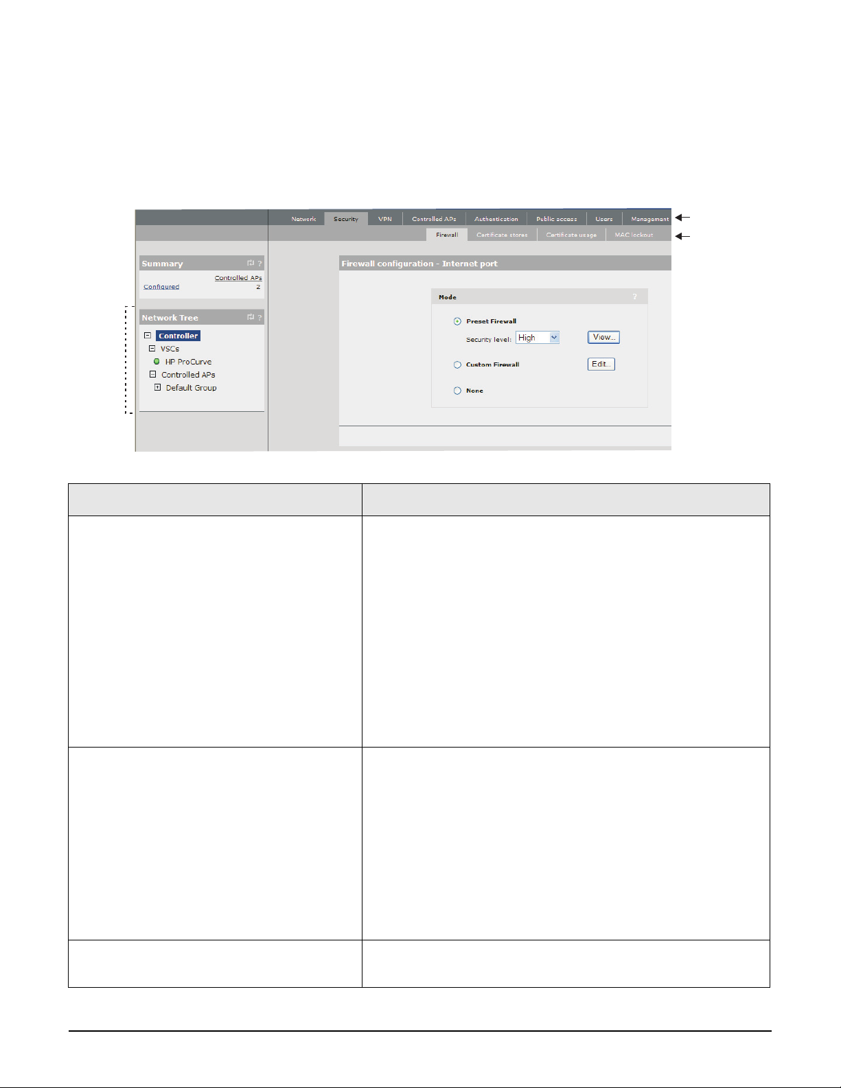
Conventions
Management tool
This guide uses specific syntax when directing you to interact with the management tool user
interface. Key user-interface elements are identified as follows:
Example directions in this guide What to do in the user interface
Select Controller >> Security > Firewall. On a non-teamed MSM7xx controller
In the Network Tree select the Controller element, then on
the main menu select Security, and then select Firewall on
the sub-menu. All elements to the left of the double angle
brackets >> are found in the Network Tree.
On an MSM7xx controller team
In the Network Tree on the team manager, select the Team
[team-name] element, then on the main menu select
Security, and then select Firewall on the sub-menu. All
elements to the left of the double angle brackets >> are found
in the Network Tree.
Select Controller > VSCs > [VSC-name]
>> Configuration.
On a non-teamed MSM7xx controller
Expand the Controller branch (click its + symbol), expand
the VSCs branch, select a [VSC-name], then select
Configuration on the main menu.
On an MSM7xx controller team
In the Network Tree on the team manager, expand the Team:
[team-name] branch (click its + symbol), expand the VSCs
branch, select a [VSC-name], then select Configuration on
the main menu.
For Password specify secret22.In the Password field enter the text secret22 exactly as
shown.
1-4
Page 27

Commands and program listings
Monospaced text identifies commands and program listings as follows:
Example Description
Introduction
About this guide
use-access-list
ip_address
ssl-certificate=URL [%s]
[ONE | TWO]
Command name. Specify it as shown.
Items in italics are parameters for which you must supply
a value.
Items enclosed in square brackets are optional. You can
either include them or not. Do not include the brackets.
In this example you can either include the “%s” or omit it.
Items separated by a vertical line indicate a choice.
Specify only one of the items. Do not include the vertical
line.
Warnings and cautions
Do not proceed beyond a WARNING or CAUTION notice until you fully understand the
hazardous conditions and have taken appropriate steps.
Warning Identifies a hazard that can cause physical injury or death.
Caution Identifies a hazard that can cause the loss of data or configuration information, create a non-
compliant condition, or hardware damage.
1-5
Page 28

Introduction
New in this release
New in this release
The following new features and enhancements have been added in releases 5.5.x:
New feature or enhancement For information see...
New APs This release supports the following new 802.11n dual-radio
access points: E-MSM430, E-MSM460, and E-MSM466. For
information, see the Quickstarts for these products.
Band steering Band steering on page 5-11
Broadcast filtering Broadcast filtering on page 5-11
Transmission protection Tx protection on page 4-30
Beamforming Tx beamforming on page 4-29
Country configuration per group Assigning country settings to a group on page 6-30
Moving multiple APs between groups Moving multiple APs between groups on page 6-29
Identify RADIUS server by host name Primary/Secondary RADIUS server on page 11-9
User agent filtering User agent filtering on page 14-10
HTTPS proxy support Support applications that use on page 14-11
Improved mobility status pages Monitoring the mobility domain on page 9-16
Manager login credentials reset Manager username/password reset on page 2-6
PayPal support PayPal service on page 14-37
LEAP support Supported 802.1X protocols on page 10-9
MSM317 switch port enhancements
Inheritance on a per port basis
Port isolation
Loop protection
Network Policy TLV support
Enhanced VLAN support
See the MSM317 Installation and Getting Started Guide.
1-6
Page 29
Introduction
Network Operating Center
Controller
Secure management tunnels
Site #1 Site #3Site #2
AP
W
L
A
N
AP
W
L
A
N
AP
W
L
A
N
Introducing the MSM7xx Controllers
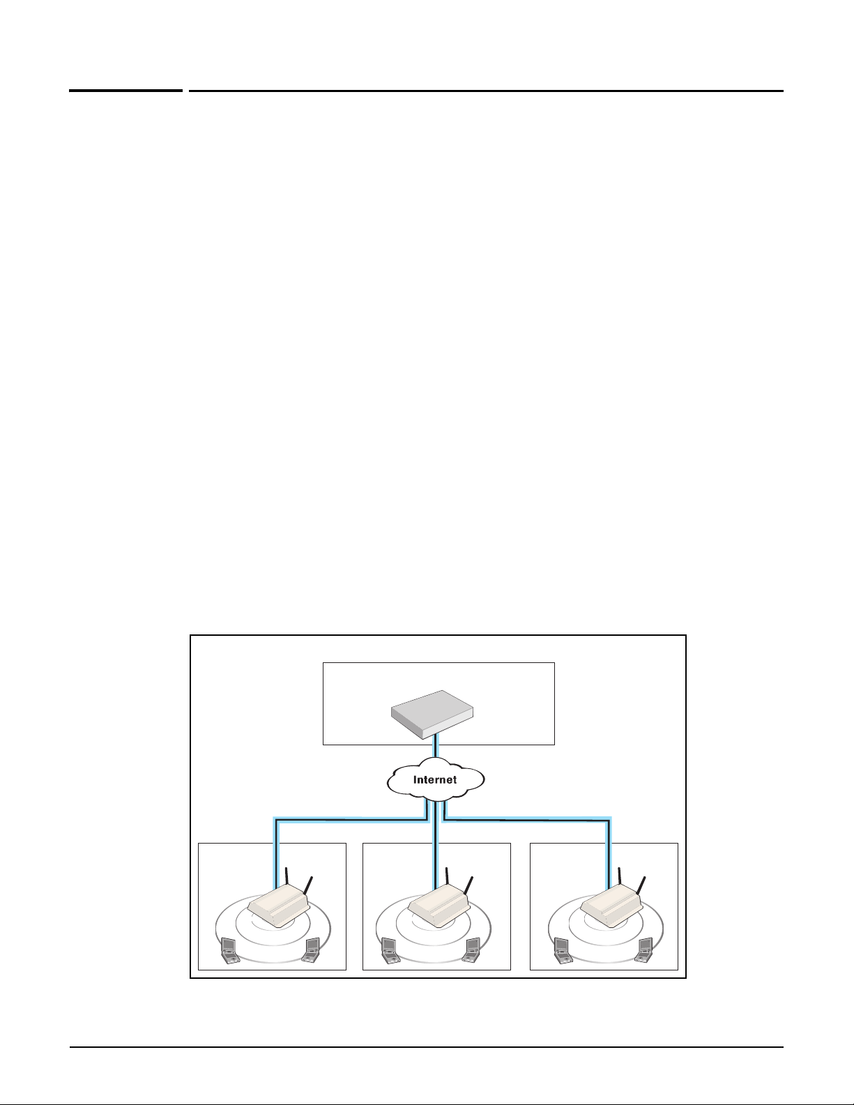
Introducing the MSM7xx Controllers
MSM7xx Controllers provide centralized management and control of intelligent HP MSM APs
for a wide range of deployments, from small Internet cafes and businesses, to large
corporations and institutions, and even entire towns.
MSM controllers let you take advantage of both distributed and centralized approaches to
deploying a wireless networking solution, letting you design a wireless infrastructure that
perfectly meets the needs of your users.
Simplified configuration, deployment, and operation
For trouble-free deployment in geographically distributed networks, HP MSM controllers
automate discovery, authentication and configuration for all installed APs. Using standard
dynamic look-up procedures, APs identify the controller to which they are assigned.
Authentication using digital certificates assures security and eliminates the risk of rogue AP
connectivity. Once authenticated, the controller establishes a secure management tunnel for
the exchange of configuration and control information with the AP.
The controller provides centralized management for all APs. It eliminates time-consuming AP
configuration, troubleshooting and maintenance tasks by providing a single management
interface for the entire group of APs it manages. The controller automates installation of AP
software updates and ensures a consistent set of services are delivered throughout the
network. All security, quality of service (QoS), and other policies can be centrally defined
through the controller's intuitive and secure Web-based management tool.
Controller managing APs installed in different physical locations
1-7
Page 30
Introduction
Secure management tunnels
Area #1
AP
Area #3Area #2
AP AP
P
U
B
L
I
C
W
L
A
N
P
U
B
L
I
C
W
L
A
N
P
U
B
L
I
C
W
L
A
N
Backbone Network
Controller
Controller team
Router
Controlled APs deployed
across a layer 3 network
In this example, all controllers are
connected to the network via their
LAN ports. The Internet port can
also be used.
Team
manager
1
2
3
4
5
Team manager sends
configuration settings
to all team members.
Team members then
update the APs that
they are managing.
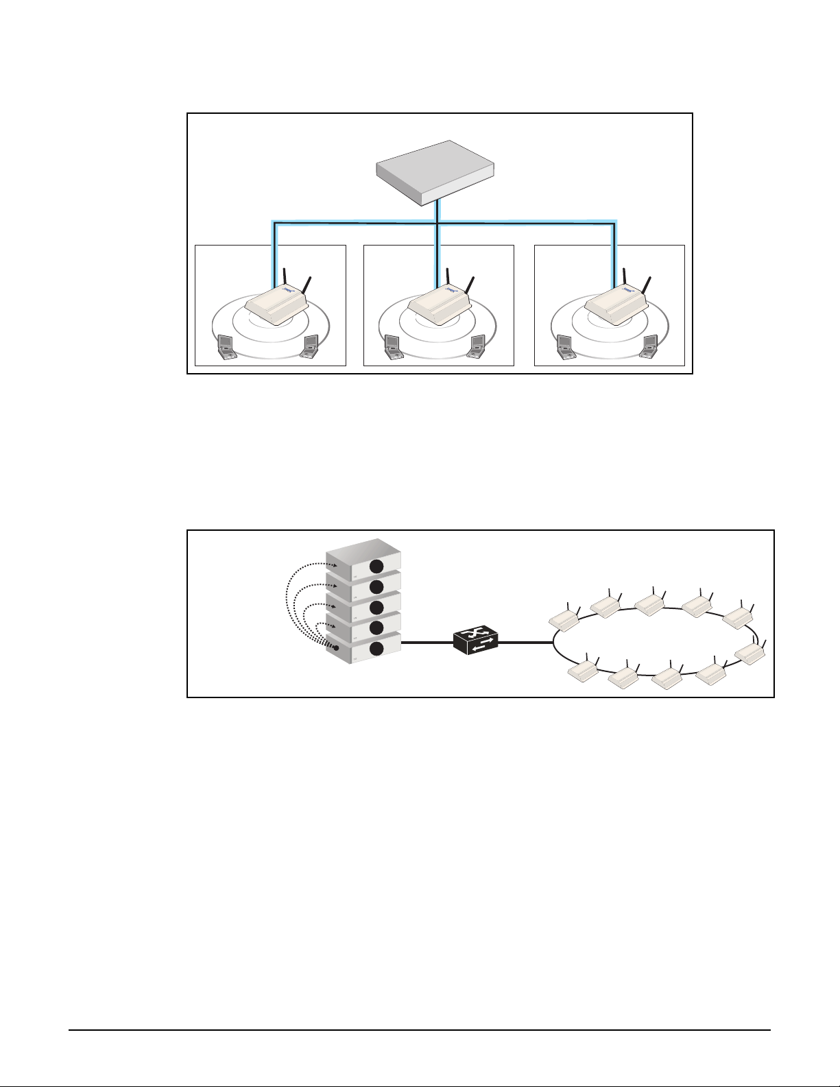
Introducing the MSM7xx Controllers
Controller managing APs installed in different areas at a single location
Controller teaming
Controller teaming enables you to easily configure and monitor multiple controllers and their
APs. Up to five controllers can be combined into a team providing support for up to 800 APs
(four controllers x 200 APs per controller plus one additional controller for backup/
redundancy). For example:
Key benefits of controller teaming include:
Scalability: Controller teaming enables you to scale up your wireless network as your
needs increase. Simply add additional APs, controllers, and licenses to meet the required
demand. Up to 800 APs are supported per controller team (four controllers x 200 APs per
controller plus one additional controller reserved for backup/redundancy).
Redundancy and failover support: A controller team provides for service redundancy
in case of failure. If one of the controllers in a team becomes inoperative (due to network
problems, hardware failure, etc.), its APs will automatically migrate to another controller
in the team allowing for continuation of services.
1-8
Centralized management and control: Configuration and monitoring of all team
members and their APs is performed using the management tool on the team manager.
The team manager is responsible for handling the addition and deletion of controlled
Page 31

Introduction
W
L
A
N
LAN port
192.168.1.1
Internet port
192.168.30.1
W
L
A
N
2
1
User B
User A
Network 2
192.168.20.0
Network 1
192.168.10.0
Network 3
192.168.30.0
User B
User A
Introducing the MSM7xx Controllers
APs, including newly discovered APs. It also displays status information for all team
members and their APs, as well as APs directly connected to the manager.
The team manager is responsible for enforcing and updating the firmware of team
members. An update to the team manager firmware triggers an update of all members
and their controlled APs, ensuring that the entire network is running the same firmware.
The synchronization of firmware between controllers and APs alleviates any potential
issue regarding software compatibility between deployed devices.
Seamless mobility
The Mobility traffic manager (MTM) feature provides for seamless roaming of wireless users,
while at the same time giving you complete control over how wireless user traffic is
distributed onto the wired networking infrastructure. MTM enables you to implement a
wireless networking solution using both centralized and distributed strategies. Some of the
deployment strategies that you can use with MTM include:
Centralized wireless traffic: All traffic from wireless users is tunneled back to a
central controller where it is egressed onto the wired infrastructure. Wireless users can
be connected to any AP within the layer 3 network serviced by MTM.
The following diagram shows a deployment where all wireless traffic is egressed onto a
specific network segment (192.168.30.0).
MTM can also be used to send traffic to different networks or VLANs based on criteria
such as username, network location, VSC, or AP group.
Traffic distribution using home networks: A home network can be assigned to each
wireless user (via RADIUS, local user accounts, or through a VSC egress). MTM can then
be used to tunnel the user’s traffic to their home network, regardless of the AP to which a
user connects within the mobility domain.
1-9
Page 32

Introduction
Home network =
Network 4
Home network =
Network 3
Traffic is sent to a different
wired network based on the
home network assigned to
each user in their account
profile.
LAN port
192.168.1.1
Internet port
192.168.40.1
W
L
A
N
W
L
A
N
2
1
User B
User A
Network 2
192.168.20.0
Network 1
192.168.10.0
Network 4
192.168.40.0
Network 3
192.168.30.0
User B User A
Home network =
Network 4
If User A roams from AP 1 to
AP2, the tunnel is rerouted to
ensure that the user stays
connected to their home
network.
LAN port
192.168.1.1
Internet port
192.168.40.1
W
L
A
N
W
L
A
N
2
1
User A
User A
Network 2
192.168.20.0
Network 1
192.168.10.0
Network 4
192.168.40.0
Network 3
192.168.30.0
User A
Roams
Introducing the MSM7xx Controllers
The following diagram shows a deployment where the wireless traffic for each user is
egressed onto a specific network segment by assigning a home network to each user.
If a user roams between APs, MTM adjusts the tunnel to maintain the user’s connection to
their home network.
1-10
Page 33

Introduction
Protected network
Public network
AP
User logs in
Access to network is granted
Access
controlled
VSC
Corporate
network
Controller
Router
Introducing the MSM7xx Controllers
Best-in-class public/guest network access service
Designed to deliver the best possible user experience, the public/guest network access
feature adapts to any client device IP address and Web proxy settings, enabling users to
connect without reconfiguring their computers.
The public access interface Web pages are fully customizable enabling service providers to
create a centrally-managed hotspot network with customized look-and-feel.
1-11
Page 34

Introduction
Safety information
Safety information
Warning Professional Installation Required
Prior to installing or using a controller, consult with a professional installer trained in RF
installation and knowledgeable in local regulations including building and wiring codes,
safety, channel, power, indoor/outdoor restrictions, and license requirements for the
intended country. It is the responsibility of the end user to ensure that installation and use
comply with local safety and radio regulations.
Cabling: You must use the appropriate cables, and where applicable, surge protection, for
your given region. For compliance with EN55022 Class-B emissions requirements use
shielded Ethernet cables.
Country of use: In some regions, you are prompted to select the country of use during
setup. Once the country has been set, the controller will automatically limit the available
wireless channels, ensuring compliant operation in the selected country. Entering the
incorrect country may result in illegal operation and may cause harmful interference to other
systems.
Safety: Take note of the following safety information during installation:
If your network covers an area served by more than one power distribution system, be
sure all safety grounds are securely interconnected.
Network cables may occasionally be subject to hazardous transient voltages (caused by
lightning or disturbances in the electrical power grid).
Handle exposed metal components of the network with caution.
The MSM7xx Controller and all directly-connected equipment must be installed indoors
within the same building (except for outdoor models / antennas), including all PoEpowered network connections as described by Environment A of the IEEE 802.3af
standard.
Servicing
There are no user-serviceable parts inside HP MSM7xx products. Any servicing, adjustment,
maintenance, or repair must be performed only by trained service personnel.
1-12
Page 35

Introduction
HP support
HP support
For support information, visit www.hp.com/networking/support and for Product Brand,
select ProCurve. Additionally, your HP-authorized networking products reseller can provide
you with assistance.
Before contacting support
To make the support process most efficient, before calling your networking dealer or HP
Support, you first should collect the following information:
Collect this information Where to find it
Product identification. On the rear of the product.
Software version. The product management tool Login page.
Network topology map, including the
addresses assigned to all relevant devices.
Your network administrator.
Getting started
Get started by following the directions in the relevant guide as follows:
Product Guide to use
MSM710, MSM730, MSM750 The provided Quickstart.
MSM760, MSM765zl The provided Installation and Getting Started Guide.
Then continue with the next chapter of this guide.
Online documentation
For the latest documentation, visit www.hp.com/networking/support and for Product
Brand, select ProCurve.
Note The MSM317 Access Device consists of both a controlled-mode-only access point and an
integrated Ethernet switch. Where appropriate, this guide makes reference to the MSM317
Installation and Getting Started Guide which must be used in conjunction with this guide
when working with the MSM317.
1-13
Page 36

Introduction
Online documentation
1-14
Page 37

Chapter 2: Management
Management
Contents
Management tool..........................................................................................................2-2
Management scenarios .........................................................................................2-2
Management station ..............................................................................................2-2
Starting the management tool..............................................................................2-2
Customizing management tool settings..............................................................2-3
Password security policies...................................................................................2-7
Management tool security features..................................................................... 2-8
Web server..............................................................................................................2-8
2
Auto-refresh ...........................................................................................................2-9
Device discovery ..........................................................................................................2-9
Mobility controller discovery.............................................................................2-10
Controlled AP discovery.....................................................................................2-11
SNMP ...........................................................................................................................2-13
Configuring the SNMP agent..............................................................................2-13
SOAP............................................................................................................................2-16
Configuring the SOAP server .............................................................................2-16
CLI................................................................................................................................2-17
Configuring CLI support.....................................................................................2-18
System time.................................................................................................................2-19
Page 38

Management
Management tool
Management tool
The management tool is a Web-based interface to the controller that provides easy access to
all configuration and monitoring functions.
Management scenarios
For complete flexibility, you can manage the controller both locally and remotely. The
following management scenarios are supported:
Local management using a computer that is connected to the LAN or Internet port on the
controller. This may be a direct connection or through a switch.
Remote management via the Internet with or without a VPN connection. See Securing
controller communications to remote VPN servers on page 16-6 for more information on
using the controller integrated VPN clients to create secure remote connections.
Management station
The management station refers to the computer that a manager or operator uses to connect
to the management tool. To act as a management station, a computer must:
Have at least Microsoft Internet Explorer 7/8 or Firefox 3.x.
Be able to establish an IP connection with the controller.
Note Before installation, ensure that TCP/IP is installed and configured on the management
station. IP addressing can be either static or DHCP.
Starting the management tool
To launch the management tool, specify the following in the address bar of your browser:
https://Controller_IP_address
By default, the address 192.168.1.1 is assigned to the LAN port on the controller. For
information on starting the management tool for the first time, see the relevant guide as
described in Getting started on page 1-13.
About
passwords
The default username and password is admin. New passwords must be 6 to 16 printable
ASCII characters in length with at least 4 different characters. Passwords are case sensitive.
Space characters and double quotes ( “ ) cannot be used. Passwords must also conform to the
selected security policy as described in Password security policies on page 2-7.
2-2
Page 39

Customizing management tool settings
To customize management tool settings, select Controller >> Management >
Management tool.
Management
Management tool
2-3
Page 40

Management
Management tool
Administrative user authentication
Login credentials for administrative users can be verified using local account settings and/or
an external RADIUS sever.
Local account settings: A single manager and operator account can be configured
locally under Manager account and Operator account on this page.
RADIUS server: Using a RADIUS server enables you to have multiple accounts, each
with a unique login name and password. Identify manager accounts using the vendor
specific attribute web-administrative-role. Valid values for this attribute are Manager
and Operator. For attribute information, see Administrator attributes on page 15-31.
To use a RADIUS server, you must define a RADIUS profile on the Controller >>
Authentication > RADIUS profiles page.
If both options are enabled, the RADIUS server is always checked first.
Authenticating administrative credentials using an external RADIUS
server
Configure RADIUS authentication as follows:
1. Define an account for the administrator on the RADIUS server. See Administrator
attributes on page 15-31.
2. On the controller, create a RADIUS profile that will connect the controller to the RADIUS
server. See Configuring a RADIUS server profile on the controller on page 11-6.
3. Under Administrator authentication, set Authenticate via to the RADIUS profile you
created. In this example, the profile is called Rad1.
4. Test the RADIUS account to make sure it is working before you save your changes.
Specify the appropriate username and password and select Tes t.
(As a backup measure you can choose to enable Local. This will allow you to log in using
the local account if the connection to the RADIUS server is unavailable.)
2-4
Page 41

Management
Management tool
Manager and Operator accounts
Two types of administrative accounts are defined: manager and operator.
The manager account provides full management tool rights.
The operator account provides read-only rights plus the ability to disconnect wireless
clients and perform troubleshooting.
Only one administrator (manager or operator) can be logged in at any given time. Options are
provided to control what happens when an administrator attempts to log in while another
administrator (or the same administrator in a different session) in already logged in. In every
case, the manager’s rights supersede those of an operator.
The following options can be used to prevent the management tool from being locked by an
idle manager or operator:
Terminates the current manager session: When enabled, an active manager or
operator session will be terminated by the login of another manager. This prevents the
management tool from being locked by an idle session until the Account inactivity
logout timeout expires.
Is blocked until the current manager logs out: When enabled, access to the
management tool is blocked until an existing manager logs out or is automatically logged
out due to an idle session.
An operator session is always terminated if a manager logs in. An active operator session
cannot block a manager from logging in.
Terminates the current operator session: When enabled, an active operator’s session
will be terminated by the login of another operator. This prevents the management tool
from being locked by an idle session until the Account inactivity logout timeout
expires.
Operator access to the management tool is blocked if a manager is logged in. An active
manager session cannot be terminated by the login of an operator.
An operator session is always terminated if a manager logs in. An active operator session
cannot block a manager from logging in.
Login control: If login to the management tool fails five times in a row (bad username
and/or password), login privileges are blocked for five minutes. Once five minutes
expires, login privileges are once again enabled. However, if the next login attempt fails,
privileges are again suspended for five minutes. This cycle continues until a valid login
occurs. You can configure the number of failures and the timeout.
Account inactivity logout: By default, if a connection to the management tool remains
idle for more than ten minutes, the controller automatically terminates the session. You
can configure the timeout.
2-5
Page 42

Management
Management tool
Passwords
Passwords must be 6 to 16 printable ASCII characters in length with at least 4 different
characters. Passwords are case sensitive. Space characters and double quotes ( “ ) cannot be
used. Passwords must also conform to the selected security policy as described below.
Manager username/password reset
Not supported on the MSM-765.
The Allow password reset via console port feature provides a secure way to reset the
manager login username/password on a controller to factory default values (admin/admin),
without having to reset the entire controller configuration to its factory default settings. To
make use of this feature you must be able to access the controller through its console (serial)
port. See Appendix B: Console ports.
Important This feature is automatically enabled after performing a reset to factory default settings.
This feature is automatically disabled after performing a software (firmware) upgrade.
Caution If you disable this feature and then forget the manager username or password, the only way
to gain access the management tool is to reset the controller to its factory default settings.
See Appendix C: Resetting to factory defaults.
To reset manager credentials on a controller
1. Connect a serial cable from the serial port on your computer to the console port on the
controller. (See Appendix B: Console ports for information on building a serial cable to
connect to your controller.)
2. Configure VT-100 terminal-emulation software on your computer as follows:
VT-100 (ANSI) terminal
Baud rate of 9600
8 data bits, 1 stop bit, no parity, and no flow control
If on Windows, disable the Use Function, Arrow, and Ctrl Keys for Windows
options.
For the Hilgrave HyperTerminal program, select the Term ina l ke y s option for the
Function, arrow, and ctrl keys act as parameter.
3. Open an appropriately-configured terminal session.
2-6
4. Power on the controller and wait for the login prompt to appear.
5. Ty pe emergency and press Enter.
6. Ty pe 1 and press Enter to reset the manager username and password.
Page 43

A typical session looks like this:
127.0.0.1 login: emergency
--------------------------
Emergency Menu
--------------------------
Device information
Serial number: SG9603P004
IP address: 16.90.48.186
Select one of the following options:
1. Reset both the manager username and password to "admin"
0. Exit
Selection: 1
Trying to reset manager login credentials....
Management
Management tool
Manager login credentials were successfully reset to:
Username = admin
Password = admin
Press any key to continue.
Password security policies
Security policies affect both manager and operator accounts. Select from one of the following
options:
Follow FIPS 140-2 guidelines: When selected, implements the following requirements
from the FIPS 140-2 guidelines:
All administrator passwords must be at least six characters long.
All administrator passwords must contain at least four different characters.
For more information on these guidelines, refer to the Federal Information Processing
Standards Publication (FIPS PUB) 140-2, Security Requirements for Cryptographic
Modules.
Follow PCI DSS 1.2 guidelines: When selected, implements the following
requirements from the PCI DSS 1.2 guidelines:
All administrator passwords must be at least seven characters long.
All administrator passwords must contain both numeric and alphabetic characters.
The settings under Login control must be configured as follows:
Lock access after nn login failures must be set to 6 or less.
Lock access for nn minutes must be set to 30 minutes or more.
2-7
Page 44

Management
Management tool
The settings under Account inactivity logout must be configured as follows:
Time o ut must be set to 15 minutes or less.
For more information on these guidelines, refer to the Payment Card Industry Data
Security Standard v1.2 document.
Management tool security features
The management tool is protected by the following security features:
Allowed addresses: You can configure a list of subnets from which access to the
management tool is permitted.
Active interfaces: You can enable or disable access to the management tool for each of
the following:
LAN port
Internet port
VPN
VLAN/GRE.
These settings also apply when SSH is used to access the command line interface.
Note Changing the security settings may cause you to lose your connection to the management
tool.
Web server
You can also configure the Web server ports from which access to the management tool is
permitted.
Secure web server port: Specify a port number for the controller to use to provide
secure HTTPS access to the management tool. Default is 443. Before reaching the
management tool login page, you must accept a security certificate. The default
certificate provided with the controller will trigger a warning message on most browsers
because it is self-signed. To remove this warning message, you must replace the default
certificate. See About certificate warnings on page 12-10.
Note Changing the secure web server port will cause you to lose your connection to the
management tool. To reconnect, you will need to specify the following address:
https://Controller_IP_address:web_server_Port_number.
2-8
Web server port: Specify a port number for the controller to use to provide standard
HTTP access to the management tool. These connections are met with a warning, and the
browser is redirected to the secure Web server port. Default is 80.
Page 45

Management
Auto-refresh icon
Device discovery
Auto-refresh
This option controls how often the controller updates the information in group boxes that
show the auto-refresh icon in their title bar. Under Interval, specify the number of seconds
between refreshes.
Device discovery
Use this page to define discovery options for:
Inter-controller discovery when using the wireless mobility feature (Chapter 9: Mobility
traffic manager)
Controller discovery by controlled APs (Chapter 6: Working with controlled APs)
Select Controller >> Management > Device discovery to open the Discovery
configuration page.
On a non-teamed controller
2-9
Page 46

Management
Device discovery
On a controller team
Mobility controller discovery
The wireless mobility feature defines a mobility domain, which is an interconnection
between multiple controllers for the purpose of exchanging mobility information on wireless
users. For more information, see Chapter 9: Mobility traffic manager.
For the controllers to interconnect, each must have the Mobility controller discovery
option enabled. In addition, one controller must be defined as the primary mobility
controller. It acts as the central site for distribution of mobility information.
There can only be one primary controller for each mobility domain. On all other controllers
set IP address of primary controller to the IP address of the primary controller.
Note All controllers in the mobility domain must be running the same software version. This
means that the first two numbers in the software revision must be the same. For example:
All controllers running 5.4.x, or all controllers running 5.5.x.
Discovery automatically takes place on both the LAN port and Internet port. VLANs are
not supported.
Network requirements
The network that interconnects the controllers and APs that make up a mobility domain must
not block any of the following ports/protocols:
UDP port 1194
UDP port 12141
UDP port 3000
2-10
UDP port 3001
UDP port 3518
TCP port 5432
Internet protocol number 47 (GRE)
Page 47

Management
Device discovery
Controller discovery and teaming
When teaming is active, several configuration scenarios are possible:
Teamed controllers operating in conjunction with one or more non-teamed
controllers: Set the team as the primary mobility controller. On the other controllers, set
the IP address of primary mobility controller parameter to the team IP address.
A single team of controllers: Enable the This is the primary mobility controller
option on the team manager.
Multiple teamed and non-teamed controllers: Set one team as the primary mobility
controller. On the other teams and controllers, set the IP address of primary mobility
controller parameter to the team IP address of the primary mobility controller.
This is the primary mobility controller
Enable this option to designate this controller as the primary mobility controller. The primary
controller is responsible for the coordination and discovery of all other controllers in the
mobility domain.
IP address of primary mobility controller
Enter the IP address of the primary mobility controller.
Controlled AP discovery
Discovery priority of this controller
Discovery priority of controller team
Sets the priority for this controller or team when discovered by a controlled AP. A value of 1
indicates the highest priority. A value of 16 indicates the lowest priority.
If multiple controllers or teams are discovered by a controlled AP, the AP will establish a
control channel with the controller or team that has the highest priority setting first. If that
controller or team is already managing the maximum number of controlled APs, the AP will
choose the controller or team with the next highest priority.
Each controller or team must have a different priority setting, otherwise AP discovery will
fail with the diagnostic Priority conflict. See Viewing all discovered APs on page 6-14.
See Discovery of controllers by controlled APs on page 6-6 for more detailed information on
the discovery process.
Important note when your network also contains controller teams
Non-teamed controllers are always higher priority than controller teams. Therefore, if your
network contains both controller teams and non-teamed controllers, APs first attempt to
establish a secure management tunnel with discovered non-teamed controllers in order of
their discovery priority. Only if all non-teamed controllers are already managing the
maximum number of controlled APs will the AP then consider controller teams in the order
of their priority.
2-11
Page 48

Management
Device discovery
The following table shows how discovery would occur for several teamed and non-teamed
controllers.
Controller or Team
Controller 1 1 1
Controller 2 2 2
Controller 3 3 3
Team 1 1 4
Team 2 2 5
Team 3 3 6
Configured discovery
priority setting
Actual order of
discovery by APs
Active interfaces
Select the physical interfaces on which the controller or team manager will listen for
discovery requests from controlled APs. The control channel to an AP is always established
on the interface on which it is discovered.
2-12
Page 49

Management
SNMP
SNMP
The controller provides a SNMP implementation supporting both industry-standard and
custom MIBs. For information on supported MIBs, see the MSM SNMP MIB Reference Guide.
Configuring the SNMP agent
Select Controller >> Management > SNMP to open the SNMP agent configuration page.
By default, the SNMP agent is enabled (SNMP agent configuration in title bar is checked)
and is active on the LAN port. If you disable the agent, the controller will not respond to
SNMP requests.
2-13
Page 50

Management
SNMP
Attributes
System name
Specify a name to identify the controller. By default, this is set to the serial number of the
controller.
Location
Specify a descriptive name for the location where the controller is installed.
Contact
Contact information for the controller.
Port
Specify the UDP port and protocol the controller uses to respond to SNMP requests. Default
port is 161.
SNMP protocol
Select the SNMP versions that the controller will support. Default is Versi o n 1 and Versio n
2c.
Notifications
Select the SNMP versions that the AP will support. Default is Version 1 and Ve rs io n 2 c.
Notifications
When this feature is enabled, the controller sends notifications to the hosts that appear in the
Notifications receivers list.
The controller supports the following MIB II notifications:
coldStart
linkUp
linkDown
authenticationFailure
In addition, the controller supports a number of custom notifications. Select Configure
Notifications. For a descriptions of these notifications, see the online help.
v1/v2 communities
Community name
Specify the password, also known as the read/write name, that controls read/write access to
the SNMP agent. A network management program must supply this name when attempting to
set or get SNMP information from the controller. By default, this is set to private.
Read-only name
This is the password that controls read-only access to the SNMP agent. A network
management program must supply this name when attempting to get SNMP information from
the controller. By default, this is set to public.
2-14
Page 51

Management
SNMP
v3 users
This table lists all defined SNMP v3 users. To add a new user, select Add New User. Up to
five users are supported. To edit a user, select its link in the Username column.
Username
The SNMP v3 username.
Security
Security protocol defined for the user. Authentication type and encryption type are separated
by a slash. For example, MD5/DES indicates MD5 authentication and DES encryption.
Access level
Type of access assigned to the user:
Read-only: The user has read and notify access to all MIB objects.
Read-write: The user has read, write, and notify access to all MIB objects.
Notification receivers
This table lists all defined SNMP notification receivers. SNMP notifications are sent to all
receivers in this list. To add a new receiver, select Add New Receiver. Up to five receivers
are supported. To edit a receiver, select its link in the Host column.
Host
The domain name or IP address of the SNMP notifications receiver to which the controller
will send notifications.
UDP port
The port on which the controller will send notifications.
Versio n
The SNMP version (1, 2c, 3) for which this receiver is configured.
Community/Username
For SNMP v1 and v2c, the SNMP Community name of the receiver.
For SNMP v3, the SNMP v3 Username of the receiver.
Security
Use these settings to control access to the SNMP interface.
Allowed addresses: List of IP address from which access to the SNMP interface is
permitted. To add an entry, specify the IP address and appropriate Mask, and then
select Add.
When the list is empty, access is permitted from any IP address.
Active interfaces: Enable the checkboxes that correspond to the interfaces from which
to allow access to the SNMP agent. For VLAN, GRE, or Mesh, select from the list. Use
Ctrl-click to select multiple objects.
2-15
Page 52

Management
SOAP
SOAP
The controller provides a SOAP interface that can be used by SOAP-compliant client
applications to perform configuration and management tasks.
An MSM SOAP/XML SDK zip file is available at www.hp.com/networking/SOAP-XML-SDK.
Look for the file corresponding to your MSM software version.
Configuring the SOAP server
Select Controller >> Management > SOAP to open the SOAP server configuration page.
By default, the SOAP server is enabled (SOAP server configuration in title bar is checked).
2-16
Server settings
Secure HTTP (SSL/TLS)
Enable this option to configure the SOAP server for SSL/TLS mode. When enabled, the
Secure Sockets Layer (SSL) protocol must be used to access the SOAP interface.
Using client certificate
When enabled, the use of an X.509 client certificate is mandatory for SOAP clients.
HTTP authentication
When enabled, access to the SOAP interface is available via HTTP with the specified
username and password.
Page 53

Management
TCP port
Specify the number of the TCP port that SOAP uses to communicate with remote
applications. Default is 448.
Security
Use these settings to control access to the SOAP interface.
Allowed addresses: List of IP address from which access to the SOAP interface is
permitted. To add an entry, specify the IP address and appropriate Mask, and then
select Add.
When the list is empty, access is permitted from any IP address.
Active interfaces: Enable the checkboxes that correspond to the interfaces from which
to allow access to the SOAP interface.
Security considerations
The SOAP server is configured for SSL/TLS mode, and the use of an X.509 client
certificate is mandatory for SOAP clients.
CLI
The SOAP server is configured to trust all client certificates signed by the default SOAP
CA installed on the controller.
Users should generate and install their own SOAP CA private key/public key certificate to
protect their devices from unauthorized access. This is important because the default
SOAP CA and a valid client certificate are provided as an example to all customers. (See
Working with certificates on page 12-5.)
CLI
The controller provides a command line interface that can be used to perform configuration
and management tasks via the serial port or an IP connection on any of the controller
interfaces, including the LAN port, Internet port, or VPN/GRE tunnel.
For information on using the CLI, see the CLI Reference Guide.
A maximum of three concurrent CLI sessions are supported regardless of the connection
type.
2-17
Page 54

Management
CLI
Configuring CLI support
Select Controller >> Management > CLI to open the Command Line Interface (CLI)
configuration page.
Secure shell access
Enable this option to allow access to the CLI via an SSH session. The CLI supports SSH on
the standard TCP port (22).
SSH connections to the CLI can be made on any active interface. Support for each interface
must be explicitly enabled under Security.
Lockout
After 10 unsuccessful login attempts via SSH, login to the CLI is locked for 5 minutes. After
the lockout expires, each subsequent unsuccessful login attempt re-activates the lockout
period. This behavior repeats until a successful login is completed.
Note Depending on your SSH configuration, your client may make several login attempts with each
connection attempt.
Supported clients
The following SSH clients have been tested with the CLI. Others may work as well:
OpenSSH
Tect ia
SecureCRT
Putty
2-18
Authenticate CLI logins using
The CLI validates login credentials (username and password) using the settings defined on
the Controller >> Management > Management tool page.
Page 55

Management
System time
Local manager account
The login username and password are the same as those defined for the local manager
account. If this account is disabled, the last known username and password for this account
are used.
Administrative user authentication settings
The login username and password use the same settings (Local and/or RADIUS) as defined
for the manager account under Administrative user authentication.
System time
Select Controller >> Management > System time to open the System time page. This
page enables you to configure the time server and set time zone information.
Note The system time page on the MSM765zl is a read-only page that displays the current time
configured on the chassis. This may or may not be the current time.
Note Setting the correct time is important when the controller is managing controlled APs, as the
time configured on the controller is used on all controlled APs. Synchronization and
certificate problems can occur if the controller time is not accurate.
Note Correct time is also important when the controller is using Active Directory to authenticate
users.
2-19
Page 56

Management
System time
Set timezone
Select the time zone in which the controller is located. If you change the time zone setting,
the new value does not take effect until you restart the controller.
Automatically adjust clock for daylight savings time changes
Enable this option to automatically update the clock based on the specified daylight savings
time (DST) rule.
Default DST rule: This is the currently active daylight savings time rule.
Customize DST rules: Select this button to define your own DST rule.
Time server protocol
Select the protocol that will be used to communicate with the time server.
Set date and time (manually)
Use this option to manually set the system date and time.
Set date and time (time servers)
Select this option to have the controller periodically contact a network time server to update
its internal clock. By default, the list contains two ntp vendor zone pools that are reserved for
HP devices. By using these pools, you will get better service and keep from overloading the
standard ntp.org server. For more information refer to: pool.ntp.org.
2-20
Page 57

Chapter 3: Network configuration
Network configuration
Contents
Port configuration........................................................................................................3-3
LAN port configuration.........................................................................................3-4
Internet port configuration...................................................................................3-5
PPPoE client ..........................................................................................................3-6
DHCP client............................................................................................................3-8
Static addressing....................................................................................................3-9
3
Network profiles ........................................................................................................3-12
About the default network profiles...................................................................3-12
To define a network profile................................................................................3-12
Address allocation......................................................................................................3-13
DHCP server......................................................................................................... 3-14
DHCP relay agent ................................................................................................3-16
VLAN support .............................................................................................................3-19
GRE tunnels ................................................................................................................3-19
Bandwidth control .....................................................................................................3-21
Internet port data rate limits..............................................................................3-22
Bandwidth levels .................................................................................................3-22
Example................................................................................................................3-23
Discovery protocols...................................................................................................3-24
LLDP agents .........................................................................................................3-24
CDP .......................................................................................................................3-24
DNS ..............................................................................................................................3-25
DNS servers..........................................................................................................3-26
DNS advanced settings ....................................................................................... 3-26
Page 58

Network configuration
IP routes ......................................................................................................................3-27
Configuration ....................................................................................................... 3-28
Network address translation (NAT).........................................................................3-30
NAT security and static mappings.....................................................................3-30
VPN One-to-one NAT...........................................................................................3-33
RIP................................................................................................................................ 3-33
IP QoS..........................................................................................................................3-34
Configuration ....................................................................................................... 3-34
Example................................................................................................................3-35
IGMP proxy.................................................................................................................3-37
3-2
Page 59

Network configuration
Port configuration
Port configuration
The Port configuration page displays summary information about all ports, VLANs, and
GRE tunnels. Open this page by selecting Controller >> Network > Ports.
Port configuration information
Status indicator: Operational state of each port, as follows:
Green: Port is properly configured and ready to send and receive data.
Red: Port is not properly configured or is disabled.
Name: Identifier for the port. To configure a port, select its name.
IP address: IP addresses assigned to the port. An address of 0.0.0.0 means that no
address is assigned.
Mask: Subnet mask for the IP address.
MAC address: MAC address of the port.
Default port settings
By default, ports are configured as follows:
Port Default IP address Default DHCP server status
LAN 192.168.1.1 Disabled.
Internet DHCP client This feature is not available on the Internet port.
3-3
Page 60

Network configuration
Port configuration
LAN port configuration
The LAN port is used to connect the controller to a wired network. To verify and possibly
adjust LAN port configuration, select Controller >> Network > Ports > LAN port.
Addressing options
The LAN port must be configured with a static IP address, because the controller cannot
function as a DHCP client on the LAN port. By default it is set to the address 192.168.1.1
For information on configuring address allocation on the LAN port via DHCP server or DHCP
relay agent, see Address allocation on page 3-13.
Management address
Use this option to assign a second IP address to the LAN port. This address provides a simple
way to separate management traffic from user traffic without using VLANs.
For example, by default the LAN port is set to 192.168.1.1 and all client devices obtain an
address on this subnet from the controller’s DHCP server. With this feature you can add
another address, say 192.168.2.1/255.255.255.0. APs can then be assigned to this subnet using
static IP addressing. Now all management traffic exchanged between the controller and the
APs is on a separate subnet.
Link settings
By default, the controller automatically adjusts link settings based on the type of equipment
the port is connected to. If needed, you can force the port to operate at a particular speed or
duplex setting.
3-4
Page 61

Network configuration
Port configuration
Internet port configuration
To verify and possibly adjust Internet port configuration, select Controller >> Network >
Ports > Internet port.
Addressing options
The Internet port supports the following addressing options:
PPPoE client on page 3-6
DHCP client on page 3-8 (default setting)
Static addressing on page 3-9
No address.
By default, the Internet port operates as a DHCP client. Select the addressing option that is
required by your ISP or network administrator and then select Configure.
Link settings
By default, the controller automatically adjusts link settings based on the type of equipment
the port is connected to. If needed, you can force the port to operate at a particular speed or
duplex setting.
Network address translation
Enable this option to permit all the computers on the network to simultaneously share the
connection on the Internet port. See Network address translation (NAT) on page 3-30.
Limit NAT port range
When enabled, the controller reserves a range of TCP and UDP ports for each authenticated,
access-controlled user starting at port 5000, and maps all outgoing traffic for the user within
the range.
3-5
Page 62

Network configuration
Port configuration
Note If you enable this feature you should not assign static NAT mappings in the range 5000 to
10000.
Size of port range
Sets the number of TCP and UDP ports reserved for each user.
PPPoE client
To configure the PPPoE client on the Internet port, select Controller >> Network > Ports
and then select PPPoE and then Configure.
Settings
Username
Specify the username assigned to you by your ISP. The controller will use this username to
log on to your ISP when establishing a PPPoE connection.
Password/Confirm password
Specify the password assigned to you by your ISP. The controller will use this password to log
on to your ISP when establishing a PPPoE connection.
Maximum Receive Unit (MRU)
Maximum size (in bytes) of a PPPoE packet when receiving. Changes to this parameter only
should be made according to the recommendations of your ISP. Incorrectly setting this
parameter can reduce the throughput of your Internet connection.
Maximum Transmit Unit (MTU)
Maximum size (in bytes) of a PPPoE packet when transmitting. Changes to this parameter
should only be made according to the recommendations of your ISP. Incorrectly setting this
parameter can reduce the throughput of your Internet connection.
Auto-reconnect
The controller will automatically attempt to reconnect if the connection is lost.
3-6
Page 63

Network configuration
Port configuration
Un-numbered mode
This feature is useful when the controller is connected to the Internet and NAT is not being
used. Instead of assigning two IP addresses to the controller, one to the Internet port and one
to the LAN port, both ports can share a single IP address.
This is especially useful when a limited number of IP addresses are available to you.
Assigned by PPPoE server
These settings are assigned to the controller by your service provider PPPoE server. The
Internet connection is not active until this occurs.
Service provider
Identifies your Internet service provider. Not all ISPs provide this information.
Connection status
Indicates the state of the PPPoE connection. If the connection is not active, a message
indicates why.
IP address
Identifies the IP address assigned to the controller by the ISP.
Mask
Identifies the subnet mask that corresponds to the assigned IP address.
Primary DNS address
Identifies the IP address of the main DNS server the controller will use to resolve DNS
requests.
Secondary DNS address
Identifies the IP address of the backup server the controller will use to resolve DNS requests.
Default gateway
Identifies the IP address of the gateway the controller will forward all outbound traffic to.
Restart Connection
Select this button to manually establish the PPPoE connection. During normal operation, you
will not need to do this because the controller will automatically reconnect if the PPPoE
connection is interrupted. However, for certain types of connection failures, the controller
may not be able to re-establish the connection, even after several retries. When this occurs,
the cause of the failure is shown in the Connection status field and you must select Restart
Connection to manually establish the connection.
3-7
Page 64

Network configuration
Port configuration
DHCP client
To configure the PPPoE client on the Internet port, select Controller >> Network > Ports
and then select DHCP Client and then Configure.
Settings
DHCP client ID
Specify an ID to identify the controller to the DHCP server.
Assigned by DHCP server
These settings are assigned to the controller by your service provider DHCP server. The
Internet connection is not active until this occurs.
Domain name
Identifies the domain the DHCP server is operating in.
IP address
Identifies the IP address assigned to the controller by the DHCP server.
Mask
Identifies the subnet mask that corresponds to the assigned IP address.
Primary DNS address
Identifies the IP address of the main DNS server the controller will use to resolve DNS
requests.
Secondary DNS address
Identifies the IP address of the backup server the controller will use to resolve DNS requests.
3-8
Default gateway
Identifies the IP address of the gateway the controller will forward all outbound traffic to.
Expiration time
Indicates how long the address is valid.
Page 65

Network configuration
Port configuration
Release
Select to release the controller IP address.
Renew
Select to renew the controller IP address.
Static addressing
To configure the PPPoE client on the Internet port, select Controller >> Network > Ports
and then select Static and then Configure.
Port settings
IP address
Specify the static IP address you want to assign to the port.
Address mask
Select the appropriate mask for the IP address you specified.
Additional IP addresses
Use these options to define additional IP addresses for use by either the VPN one-to-one NAT
feature or the public IP address feature. Only one of these features can be active.
Type of addresses
Select either the VPN one-to-one NAT or Public IP address option.
VPN one-to-one NAT
When this feature is enabled, the controller can assign a unique IP address to each IPSec or
PPTP VPN connection made by a user to a remote server via the Internet port. Addresses are
assigned as defined in the Address pool.
This feature can only be used with authenticated, access-controlled users.
3-9
Page 66

Network configuration
Port configuration
To reduce the number of addresses that need to be defined, the controller will use the same
address for multiple users as long as they are establishing a connection with different VPN
servers.
Use this feature when all of the following conditions are true:
Users intend to make IPSec or PPTP VPN connections with a remote site via the Internet
port on the controller.
NAT is enabled on the controller. (In its default configuration, NAT translates all IP
address on the local network to a single public IP address; the address assigned to the
Internet port on the controller. As a result, all user sessions to an external resource
appear to originate from the same IP address. This can cause a problem with remote VPN
servers that require a unique IP address for each user session.)
The remote VPN server requires that each user have a unique IP address.
Note External devices cannot initiate connections with users via the address assigned by this
feature.
Assigning addresses to users
To make use of this feature, each user account must have the VPN one-to-one NAT option
enabled. Do this as follows:
If using the local user accounts (defined on the Controller >> Users menu), enable the
VPN one-to-one NAT option in the account profile or subscription plan that is assigned
to the user. See Defining account profiles on page 10-32 and Defining subscription
plans on page 10-35.
If using Active Directory, enable the VPN one-to-one NAT option in the account profile
(see Defining account profiles on page 10-32) that is assigned to an Active Directory
group (see Configuring an Active Directory group on page 11-13).
If using a RADIUS server, add the following Colubris AV-Pair value to the user’s account:
one-to-one-nat=1. For more information on setting attributes, see Default user one-
to-one NAT on page 15-53 and One-to-one NAT on page 15-69.
Address pool
The address pool contains all the IP addresses that can be assigned to users. You can define
up to 30 addresses.
Addresses must be valid for the network to which the Internet port is connected. Specify a
single address or an address range as follows: address1-address2. For example, the following
defines a range of 20 addresses: 192.168.1.1-192.168.1.20
Public IP address
This feature enables the integrated DHCP server on the controller to assign public IP
addresses to users. A user with a public IP address is visible on the protected network
connected to the Internet port, instead of being hidden by the controller’s NAT feature. This
makes it possible for external devices to create connections with a user’s computer on the
internal network.
3-10
Page 67

Network configuration
Port configuration
Public IP addresses are assigned by the integrated DHCP server using the addresses specified
in the Address pool. Whenever possible, this feature will assign the same public IP address
to a user each time they connect.
When you enable public IP address support in a subscription plan, an additional setting is
available called Reserve public IP address. When this option is enabled, the public IP
assigned to a user is reserved until the user’s subscription plan expires. This means that the
address is reserved, even if the user is not logged in.
When a public IP address is assigned to a user:
The user cannot access any VLANs, VPNs, or GRE tunnels configured on the controller.
The user cannot establish more than one concurrent session.
Note If a user’s account is configured for public IP address support and there is no free public IP
address in the pool when the user tries to login, the login is refused.
Assigning public IP addresses to users
To obtain a public IP address, a user’s account must have its Public IP address option
enabled. Do this as follows:
If using the local user accounts (defined on the Controller >> Users menu), enable the
Public IP address option in the account profile or subscription plan that is assigned to
the user. See Defining account profiles on page 10-32 and Defining subscription plans
on page 10-35.
If using Active Directory, enable the Public IP address option in the account profile (see
Defining account profiles on page 10-32) that is assigned to an Active Directory group.
To set up an Active Directory group, see Configuring an Active Directory group on
page 11-13.
If using a RADIUS server, add the following Colubris AV-Pair value to the user’s account:
use-public-ip-subnet=1. For more information, see Default user public IP address
on page 15-54 and Public IP address on page 15-70.
DHCP server lease time
Use this setting to define the amount of time the public IP address lease will be valid. This
setting only applies to public IP addresses. It overrides the DHCP lease time set by selecting
Controller >> Network > Address allocation > DHCP server.
Address pool
The address pool contains all the public IP addresses that can be assigned to users. You can
define up to 30 addresses.
Addresses must be valid for the network to which the Internet port is connected. Specify a
single address or an address range as follows: address1-address2. For example, the following
defines a range of 20 addresses: 192.168.1.1-192.168.1.20
3-11
Page 68

Network configuration
Network profiles
Network profiles
Network profiles let you define the characteristic of a network and assign a friendly name to
it. Profiles make it easy to configure the same settings in multiple places on the controller.
For example, if you define a profile with a VLAN ID of 10, you could use that profile to:
Configure VLAN 10 on the controller’s Internet or LAN port using the Controller >>
Network > Ports page.
Configure VLAN 10 as the egress network for a group of APs when binding them to a VSC
using the Controlled APs > [group] >> VSC bindings page.
Configure VLAN 10 as the local network for an AP using the Controlled APs >>
Configuration > Local network page.
About the default network profiles
Two network profiles are created by default: LAN port network and Internet port
network. These profiles are associated with the two physical Ethernet ports on the
controller. You can rename these profiles, but you cannot assign a VLAN to them or delete
them. You can use these profiles to send untagged traffic to a specific port on the controller.
Both ports are considered to be local networks on the controller, which means that they
automatically map the network that is assigned to each physical port as a local network on
the controller. However, the LAN and Internet port network profiles can also be assigned as a
local network on an AP (for example, using the Controlled APs >> Configuration > Local
networks page). When this is done, both profiles refer to the untagged Ethernet port on the
AP.
To define a network profile
1. Select Controller >> Network > Network profiles.
3-12
Page 69

2. Select Add New Profile.
3. Configure profile settings as follows:
Under Settings, specify a Name for the profile.
To assign a VLAN, select VLAN and then specify an ID.
If the profile will be used on an Ethernet port, you can also define a range of VLANs.
This enables a single VLAN definition to span a large number of contiguously
assigned VLANs. Specify the range in the form X-Y, where X and Y can be 1 to 4094.
For example: 50-60.
Network configuration
Address allocation
An IP address cannot be assigned to a VLAN range.
You can define more than one VLAN range by using multiple profiles. Each range
must be distinct and contiguous.
4. Select Save.
Address allocation
The controller can operate as a DHCP server or DHCP relay agent on the LAN port. This
enables it to assign IP addresses to downstream devices connected to the LAN port.
By default, address allocation is disabled. To configure address allocation settings, select
Controller >> Network > Address allocation.
For information on VPN address pool, see Configure an IPSec profile for wireless client VPN
on page 16-4.
3-13
Page 70

Network configuration
Address allocation
DHCP server
The DHCP server can be used to automatically assign IP addresses to devices that are
connected to the controller via the LAN port or client data tunnel.
Note Do not enable the DHCP server if the LAN port is connected to a network that already has
an operational DHCP server.
When the DHCP server is active, users can still connect using static IP addresses assigned
on different subnets. To configure this feature, select Public access > Access control
and under Client options, select Allow any IP address.
The DHCP settings on this page are always used by the default VSC. For additional
flexibility, separate DHCP servers can enabled on other access-controlled VSCs to assign
addresses to users. See DHCP server on page 5-30.
The DHCP server feature is not supported when controller teaming is active.
To configure the internal DHCP server, select Controller >> Network > Address
allocation, select DHCP server, and then Configure.
3-14
Page 71

Network configuration
Address allocation
Addresses
Start / End
Specify the starting and ending IP addresses that define the range of addresses the DHCP
server can assign to client stations. The address assigned to the controller is automatically
excluded from the range.
Gateway
Specify the IP address of the default gateway the controller will assign to DHCP users. In
most cases you will specify the IP address of the controller LAN port as the Gateway.
DNS servers to assign to client stations
Lists the IP addresses of the DNS servers that the controller will assign to users. You can
define DNS options by selecting Network > DNS.
Fixed leases
Use this feature to permanently reserve an IP addresses lease for a specific device. This
ensures that the device is always reachable at the same address on the network, but does not
require a static address to be set directly on the device itself. This table lists all permanently
reserved addresses. Up to 255 fixed leases can be defined.
To assign a specific IP address to a client station specify the following and select Add:
MAC address: MAC address of the client station in the format: nn:nn:nn:nn:nn:nn.
IP address: IP address that will be assigned to the client station in the format:
nnn.nnn.nnn.nnn.
Unique identifier: A number that identifies the device. Must be unique to all DHCP
clients on the network. Generally set to the MAC address of the client station. This
parameter is optional unless MAC masquerading is being performed by the client station.
Settings
Domain name
Specify the domain name the controller will return to DHCP users. Typically, this will be your
corporate domain name.
The host name in the currently installed SSL certificate is automatically assigned as the
domain name of the controller. The factory default SSL certificate that is installed on the
controller has the host name wireless.colubris.com.
3-15
Page 72

Network configuration
Address allocation
You do not have to add this name to your server for it to be resolved. The controller
intercepts all DNS requests it receives. It resolves any request that matches the certificate
host name by returning the IP address assigned to the Internet port. All other DNS requests
are forwarded to the appropriate DNS servers as configured on the Controller > Network >
DNS page.
To summarize, this means that by default, any DNS request by a user that matches
wireless.colubris.com will return the IP address of the controller’s Internet port.
Lease time
Specify the lease time (in seconds) that the controller will assign to all assigned addresses. As
long as a user remains connected their address is automatically renewed when the lease time
expires. If a user disconnects without releasing their address, then the address remains
reserved until the lease time expires. If you have a small address pool and a large user
turnover, setting a long lease time may cause you to run out of addresses even though they
are not really in use.
Logout HTML user on discovery request
When enabled, the controller will log out a client station if a DHCP discovery request is
received from the client station while a DHCP address lease is currently assigned.
This feature is useful when multiple users share the same client station. If a user forgets to
log out before turning off the client station, the next user will have to wait until the lease
expires before being able to log in.
Listen for DHCP requests on
Select the port on which the controller will listen for DHCP requests from client stations.
LAN port: Listen for requests on the LAN port.
Client data tunnel: Enable this option when the client data tunnel feature is active on
one or more VSCs, and you want tunneled client stations to be able to receive an IP
address from the controller’s DHCP server.
Controller discovery
Use this option to define controller discovery information for controlled APs. See DHCP
discovery on page 6-8.
Add the IP address for each controller that is active on the network. When working with a
controller team you should add the IP address of each team member.
This list is sent to all devices that request an IP address, encoded as DHCP option 43 (Vendorspecific information). However, this information is only interpreted by HP ProCurve APs that
are operating in controlled mode. Controlled mode APs use these addresses to connect with
the controllers in the order that they appear in the list.
3-16
DHCP relay agent
The controller provides a flexible DHCP relay implementation. It can listen for requests on
the LAN port or client data tunnel and forward them to a DHCP via any of the controller’s
physical or logical interfaces.
Page 73

Network configuration
Address allocation
Note For additional flexibility, separate DHCP relay agents can be enabled on access-controlled
VSCs. See DHCP relay agent on page 5-31.
Use the following guidelines when configuring DHCP relay:
Routes must be defined on the DHCP server, so that the DHCP server can successfully
send DHCP response packets back to the DHCP relay agent running on the controller.
These should be static and persistent HOST routes that must identify the IP address
assigned to the controller’s LAN port or additional VSC relay IP address, (i.e. 192.168.1.1).
On Windows, such a static route would look like this:
route add 192.168.1.1 mask 255.255.255.255 10.10.10.22 metric 1 –p
DHCP relay is not supported via the Internet port when it is operating as a PPPoE client.
DHCP relay cannot work via the Internet port if the internal firewall is set to High and
NAT is enabled on the Internet port. The DHCP server must be able to ping the assigned
address to prevent duplicate assignments.
To configure the internal DHCP server, select Controller >> Network > Address
allocation, select DHCP relay agent, and then Configure.
Settings
Listen for DHCP requests on
Select the port on which the controller will listen for DHCP requests from users.
Listen for requests on
LAN port: Listens for DHCP requests on the LAN port and relay them to the remote
DHCP server.
Client data tunnel: Enable this option when the client data tunnel feature is active on
one or more VSCs, and you want tunneled users to be able to receive an IP address via the
DHCP relay agent. See Client data tunnel on page 5-13.
3-17
Page 74

Network configuration
Address allocation
The following two fields let you attach information to the DHCP request (as defined by DHCP
relay agent information option 82) which lets the DHCP server identify the controller.
Circuit ID: Use this field to identify the user that issued the DHCP request.
Remote ID: Use this field to identify the controller.
You can use regular text in combination with the following placeholders to create the
information in each field. Placeholders are automatically expanded when the request is sent.
The following placeholders can be used:
%S: SSID to which the user is associated.
%B: BSSID to which the user is associated.
%V: VLAN to which the user is mapped.
Server
Primary DHCP server address
Specify the IP address of the first DHCP server to which the controller should forward DHCP
requests.
Secondary DHCP server address
Specify the IP address of the backup DHCP server to which the controller should forward
DHCP requests.
Note The DHCP servers must be reachable via one of the ports on the controller.
Routes must be defined on the DHCP server so that the DHCP server can successfully
send DHCP response packets back to the DHCP relay agent running on the controller.
These should be static and persistent HOST routes that must identify the IP address
assigned to the controller’s LAN port or an additional VSC relay IP address, (i.e.
192.168.1.1). On Windows, such a static route would look like this:
route add 192.168.1.1 mask 255.255.255.255 10.10.10.22 metric 1 –p
DHCP relay is not supported via the Internet port when it is operating as a PPPoE client.
DHCP relay cannot work via the Internet port if the internal firewall is set to High and
NAT is enabled on the Internet port. The DHCP server must be able to ping the assigned
address to prevent duplicate assignments.
Extend Internet port subnet to LAN port
When enabled, the controller will alter the DHCP address requests from client stations so that
they appear to originate from the network assigned to the Internet port on the controller. This
will cause the DHCP server to assign IP addresses on this network to all client stations. The
controller handles all mapping between the two subnets internally.
3-18
Page 75

Network configuration
VLAN support
For L2 connected APs operating in controlled mode:
Enable the Client data tunnel option under Settings. (If teaming is active, the client
data tunnel is automatically used.)
Enable the Always tunnel client traffic option on the VSC profile page under Vir t ual
AP > Client data tunnel.
VLAN support
VLAN configuration is discussed in Chapter 7: Working with VLANs.
GRE tunnels
To view and configure GRE tunnel definitions, select Controller >> Network > Ports.
Initially, no GRE tunnels are defined.
3-19
Page 76

Network configuration
GRE tunnels
To add a tunnel, select Add New GRE Tunnel. The Add/Edit GRE tunnel page opens.
Define tunnel settings as follows:
Name: Tunnel name.
Local tunnel IP address: Specify the IP address of the controller inside the tunnel.
Remote tunnel IP address: Specify the IP address of the remote device inside the
tunnel.
Tunnel IP mask: Specify the mask associated with the IP addresses inside the tunnel.
GRE peer IP address: Specify the IP address of the remote device that terminates the
tunnel.
3-20
Page 77

Network configuration
Bandwidth Control
Internet Port
Data Rate
Limit
Level
User
Data Rate
Limits
User
traffic
Management
traffic
Internet
Port
Very High
High
Normal
Low
Traffic from
the site access list
Bandwidth control
Bandwidth control
The controller incorporates a bandwidth management feature that enables control of all user
traffic flowing through the controller.
To configure Bandwidth management, select Controller >> Network > Bandwidth
Control.
Bandwidth control has two separate components: Internet port data rate limits and
bandwidth levels. They interact with the data stream as follows:
3-21
Page 78

Network configuration
Bandwidth control
Internet port data rate limits
These settings enable you to limit the total incoming or outgoing data rate on the Internet
port. If traffic exceeds the rate you set for short bursts, it is buffered. Long overages will
result in data being dropped.
To utilize the full available bandwidth, the Maximum transmit rate and Maximum receive
rate should be set to match the incoming and outgoing data rates supported by the
connection established on the Internet port.
Bandwidth levels
The controller provides four levels of traffic priority that you can use to manage traffic flow:
Very High, High, Normal, and Low. The settings for each level are customizable, allowing
performance to be tailored to meet a wide variety of scenarios.
Assigning traffic to a bandwidth level
Traffic can be assigned to a specific bandwidth level for each VSC and for each user. For
bandwidth control to be operational, you must first enable the Internet port data rate
limits option. Once this is done, you can assign traffic to bandwidth levels as follows:
In a VSC, select the default level for all user traffic in the Bandwidth control box. This
level applies to users who do not have a specific assignment in their user account.
In a user’s account profile, set the Bandwidth level in the Bandwidth limits box.
Or if you are using a RADIUS server to validate user logins, set the bandwidth level using
a Colubris AV-Pair value. See Bandwidth level on page 15-68.
To control the default bandwidth level for all users, see Default user bandwidth level on
page 15-51.
3-22
Page 79

Network configuration
Bandwidth control
Note Management traffic (which includes RADIUS, SNMP, and administrative sessions) is
assigned to bandwidth level Ver y Hi gh and cannot be changed.
All traffic assigned to a particular bandwidth level shares the allocated bandwidth for
that level across all VSCs. This means that if you have three VSCs all assigning user traffic
to High, all users share the bandwidth allocated to the High level.
Customizing bandwidth levels
Bandwidth levels are arranged in order of priority from Very High to Low. Priority determines
how free bandwidth is allocated once the minimum rate is met for each level. Free bandwidth
is always assigned to the higher priority levels first.
Bandwidth rates for each level are defined by taking a percentage of the maximum transmit
and receive rates defined for the Internet port. Each bandwidth level has four rate settings:
Transmit rate - guaranteed minimum: Minimum amount of bandwidth that will be
assigned to a level as soon as outgoing traffic is present on the level.
Transmit rate - maximum: Maximum amount of outgoing bandwidth that can be
consumed by the level. Traffic in excess is buffered for short bursts, and dropped for
sustained overages.
Receive rate - guaranteed minimum: Minimum amount of bandwidth that will be assigned
to a level as soon as incoming traffic is present on the level.
Receive rate - maximum: Maximum amount of incoming bandwidth that can be
consumed by the level. Traffic in excess is buffered for short bursts, and dropped for
sustained overages.
Example
For example, assume that transmit bandwidth is configured as follows:
Tra ns mi t r ate s
Min Max
Very High
High
Normal
Low
20 20
40 100
20 100
20 20
Next, assume the following bandwidth requirement occurs on transmitted user data:
High requires 70%, which is 30% more than its minimum.
Normal requires 50%, which is 30% more than its minimum.
There is no traffic on Very High or Low.
3-23
Page 80

Network configuration
Discovery protocols
Since both High and Normal require bandwidth in excess of their guaranteed minimum, each
is allocated their guaranteed minimum. This leaves 40% of the bandwidth free to be assigned
on a priority basis. High has more priority than Normal, so it takes as much bandwidth as
needed. In this case it is 30%, which brings High up to 70%. This leaves 10% for Normal, which
is not enough. Traffic is buffered for a short period, and then dropped.
If at the same time Very High traffic is sent, this level immediately steals 20% from the lower
levels. In this case, 10% is taken from Normal, returning it to its minimum guaranteed level,
and 10% is taken from High.
Discovery protocols
The controller supports two protocols (LLDP and CDP) that provide a mechanism for devices
on a network to exchange information with their neighbors.
To these protocols, select Controller >> Network > Discovery protocols.
3-24
LLDP agents
For a complete discussion of all LLDP options, see Chapter 17: LLDP on page 17-1.
CDP
The controller can be configured to transmit CDP (Cisco Discovery Protocol) information on
the LAN and Internet ports. This information is used to advertise controller information to
third-party devices, such as CDP-aware switches. Network managers can retrieve this
information allowing them to determine the switch ports to which different controllers are
connected.
Page 81

The controller always listens for CDP information on the LAN and Internet ports, even when
this option is disabled, to build a list of autonomous APs. CDP information from third-party
devices and controlled APs is ignored.
Note Controlled APs always send CDP information.
DNS
The controller provides several options to customize DNS handling. To configure these
options, select Controller >> Network > DNS. The configuration options on this page
change depending on the address option that is active on the Internet port.
When the Internet port is configured to obtain an IP address via PPPoE or DHCP
Network configuration
DNS
When the Internet port is configured to use a static IP address
3-25
Page 82

Network configuration
DNS
Note When using Active Directory for user authentication, set the DNS servers to be the Active
Directory servers or the devices that provide SRV records.
DNS servers
Dynamically assigned servers
Shows the DNS servers that are dynamically assigned to the controller when PPPoE or DHCP
is used to obtain an IP address on the Internet port.
Override dynamically assigned DNS servers
Enable this checkbox to use the DNS servers that you specify on this page to replace those
that are assigned to the controller.
Server 1
Specify the IP address of the primary DNS server for the controller to use.
Server 2
Specify the IP address of the secondary DNS server for the controller to use.
Server 3
Specify the IP address of the tertiary DNS server for the controller to use.
DNS advanced settings
DNS cache
Enable this checkbox to activate the DNS cache. Once a host name is successfully resolved to
an IP address by a remote DNS server, it is stored in the cache. This speeds up network
performance, because the remote DNS server does not have to be queried for subsequent
requests for this host.
An entry stays in the cache until one of the following is true:
An error occurs when connecting to the remote host.
The time to live (TTL) of the DNS request expires.
The controller restarts.
DNS switch on server failure
Controls how the controller switches between servers:
When enabled, the controller switches servers if the current server replies with a DNS
server failure message.
3-26
When disabled, the controller switches servers if the current server does not reply to a
DNS request.
Page 83

Network configuration
IP routes
DNS switch over
Controls how the controller switches back to the primary server.
When enabled, the controller switches back to the primary server once the primary
server becomes available again.
When disabled, the controller switches back to the primary server only when the
secondary server becomes unavailable.
DNS interception
When enabled, the controller intercepts all DNS requests and relays them to the configured
DNS servers. DNS interception must be enabled to support:
Redirection of users to the public access interface login page when the controller cannot
resolve the domain requested by the user. For example, if the user is using a private or
local domain as the default home page in its browser.
Users configured to use HTTP proxy.
Users with static IP addresses when the Allow any IP address option is enabled on the
Public access > Access control page.
When disabled, the controller does not intercept any DNS requests, enabling devices to
use a DNS server other than the controller. To support this option, you must set
Network > Address allocation to DHCP relay agent or Static.
Note When Network > Address allocation is set to DHCP Server the controller always
returns its own address as the DNS server.
IP routes
The routing module on the controller provides the following features:
Compliance with RFC 1812, except for multicast routing
Supports Classless Inter Domain Routing (CIDR)
Supports Routing Internet Protocol (RIP) versions 1 and 2 in active or passive mode.
Output from the router is sent to the appropriate logical interface based on the target address
of the traffic. Supported logical interfaces include:
VLAN
Untagged
IPSec client
PPTP client
GRE tunnel
3-27
Page 84

Network configuration
IP routes
Configuration
To view and configure IP routes, select Controller >> Network > IP routes.
Active routes
This table shows all active routes on the controller. You can add routes by specifying the
appropriate parameters and then selecting Add.
The routing table is dynamic and is updated as needed. This means that during normal
operation the controller adds routes to the table as required. You cannot delete these system
routes.
The following information is shown for each active route:
Interface: The port through which traffic is routed. When you add a route, the controller
automatically determines the interface to be used based on the Gateway address.
Destination: Traffic addressed to this IP address or subnet is routed.
Mask: Number of bits in the destination address that are checked for a match.
Gateway: IP address of the gateway to which the controller forwards routed traffic
(known as the next hop).
An asterisk is used by system routes to indicate a directly connected network.
Routes cannot be manually specified for IPSec. These routes are automatically added by
the system based on the settings for the IPSec security association.
Metric: Priority of a route. If two routes exist for a destination address, the controller
chooses the one with the lower metric.
3-28
Default routes
The Default routes table shows all default routes on the controller. Default routes are used
when traffic does not match any route in the Active routes table. You can add routes by
specifying the appropriate parameters and then selecting Add.
Page 85

Network configuration
IP routes
The routing table is dynamic and is updated as needed. If more than one default route exists,
the first route in the table is used.
The following information is shown for each default route:
Interface: The port through which traffic is routed. When you add a route, the controller
automatically determines the interface to be used based on the Gateway address.
Gateway: IP address of the gateway to which the controller forwards routed traffic
(known as the next hop).
An asterisk is used by system routes to indicate a directly connected network.
Metric: Priority of a route. If two routes exist for a destination address, the controller
chooses the one with the lower metric.
Persistent routes
Persistent routes are automatically deleted and then restored each time the interface they are
associated with is closed and opened. When the routes are active, they also appear in the
Active routes table.
PPTP client
The controller provides an Auto-route discovery option to enable it to automatically
discover and add routes for IP addresses on the other side of a Point-to-Point Tunnelling
Protocol (PPTP) tunnel. The addresses must be part of the remote domain as specified on the
Controller >> VPN > PPTP client page. Routes are added only when an attempt is made to
access the target addresses.
About PPTP client routes (Internet port)
If you disabled the Auto-route discovery option (VPN > PPTP client), or if you need to
access IP addresses that are not part of the specified domain, you must define the
appropriate persistent routes.
About PPTP server routes (Internet port)
Activation of the route can be triggered by a specific username. When a user establishes a
connection with the controller PPTP server, its username is checked against the persistent
routes list and if a match is found, the route is enabled.
3-29
Page 86

Network configuration
Internet
Web
server
Web Page
Web Page
192.168.1.2
NAT
192.168.1.3
ISP
addressed to
192.168.1.2
addressed to
202.125.11.26
Internal addresses are invisible
to computers on the Internet.
All traffic uses the same
external IP address
assigned by the ISP.
202.125.11.26
HTTP request
AP
Controller
Network address translation (NAT)
Network address translation (NAT)
Network address translation is an address mapping service that enables one set of IP
addresses to be used on an internal network, and a second set to be used on an external
network. NAT handles the mapping between the two sets of addresses.
Generally NAT is used to map all addresses on an internal network to a single address for use
on an external network like the Internet. The main benefits are that NAT:
Enables several devices to share a single connection
Effectively hides the IP addresses of all devices on the internal network from the external
network.
This is illustrated as follows:
3-30
NAT can be useful in conjunction with virtual private network (VPN) connections. When two
networks are connected through a VPN tunnel, it may be desirable to obscure the address of
local computers for security reasons.
NAT security and static mappings
One of the benefits of NAT is that it effectively hides the IP addresses of all devices on the
internal network an external network. In some cases, however, it is useful to make a
computer on the internal network accessible externally. For example, a Web server or FTP
server.
Static NAT mapping addresses this problem. Static NAT mapping enables you to route
specific incoming traffic to an IP address on the internal network. For example, to support a
Web server, you can define a static NAT mapping to route traffic on TCP port 80 to an internal
computer running a Web server.
Page 87

Network configuration
Network address translation (NAT)
A static NAT mapping allows only one internal IP address to act as the destination for a
particular protocol (unless you map the protocol to a nonstandard port). For example, you
can run only one Web server on the internal network.
Note If you use a NAT static mapping to enable a secure (HTTPS) Web server on the internal
network on TCP port 443, remote access to the management tool is no longer possible,
as all incoming HTTPS requests are routed to the internal Web server and not to the
management tool. You can change the default management port (TCP 443) to an
alternate unused TCP port in this case.
If you create a static mapping, the firewall is automatically opened to accept the traffic.
However, this firewall rule is not visible on the Firewall configuration page (it is
maintained internally by the controller).
Common applications are affected by NAT as follows:
Application NAT
FTP (passive mode) Requires a static mapping to function.
FTP (active mode) Requires a static mapping to function.
NetMeeting Requires a static mapping to function.
Telnet Requires a static mapping to function.
Windows networking No effect
The controller provides pre-configured static mappings for most common applications,
which you can enable as needed.
Most Web browsers use FTP in active mode. Some browsers provide a configuration option
that enables you to alter this. Use the following steps to change this behavior in Microsoft
Internet Explorer.
1. Select Tools > Internet options to open the Internet options dialog.
2. Select the Advanced tab.
3. Under Browsing, enable the Use Passive FTP for compatibility with some firewalls
and DSL modems checkbox.
3-31
Page 88

Network configuration
Web
server
Web
browser
FTP
client
FTP
server
192.168.1.2
192.168.1.3
FTP traffic
Web (HTTP) traffic
192.168.1.1
NAT
202.125.11.26
Controller
AP
Internet
Network address translation (NAT)
NAT example
The following example shows you how to configure static NAT mappings to run a Web server
and an FTP server on the internal network. This scenario might occur if you use the
controller in an enterprise environment.
By creating static NAT mappings, FTP and HTTP (Web) traffic can be routed to the proper
user. Note that the addresses of these stations are still not visible externally. Remote
computers send their requests to 202.125.11.26, and the controller routes them to the proper
client.
Use the following steps to configure the controller to support this example,.
1. Select Controller >> Network > NAT > Add New Static NAT Mapping.
2. On the NAT mappings page, select Add New Static NAT Mapping.
3. Under Requests for, select Standard Services, and then select http (TCP 80).
4. Under Translate to, specify the IP address of the Web server, for example 192.168.1.2.
The Settings box should now look similar to this:
5. Select Add to save your changes and return to the NAT mappings page. The new mapping
is added to the table.
3-32
Page 89

Network configuration
RIP
6. To support the FTP server, create two additional mappings with the following values:
Set Standard Services to ftp-data (TCP 20) and set IP address to 192.168.1.3.
Set Standard Services to ftp-control (TCP 21) and set IP address to
192.168.1.3.
The NAT mappings table should now show all three mappings:
VPN One-to-one NAT
This feature can only be used with authenticated, access-controlled users. It is only
supported when a static IP address is assigned to the Internet port. It is configured by
selecting Network > Ports > Internet port > Static > Additional IP addresses. See VPN
one-to-one NAT on page 3-9.
RIP
The controller supports Routing Information Protocol (RIP) versions 1 and 2. RIP can
operate in one of two modes on the interfaces you select.
Passive mode: The controller listens for routing broadcasts to update the routing table,
but does not broadcast its own routes.
Active mode: The controller listens for routing broadcasts to update the routing table,
and also broadcast its own routes.
For example:
Note RIP is not supported if you are using PPPoE on the Internet port.
3-33
Page 90

Network configuration
IP QoS
IP QoS
To ensure that critical applications have access to the required amount of wireless
bandwidth, you can classify packets destined for the wireless interface into priority queues
based on a number of criteria. For example, you can use any of the following to place data
packets in one of four priority queues for transmission onto the wireless interface:
TCP source port
UDP source port
Destination port
Port ranges
You configure IP quality of service (QoS) by creating IP QoS profiles that you can then
associate with VSCs or use for global wireless settings. You can configure as many as 32 IP
QoS profiles on the controller. You can associate as many as 10 IP QoS profiles with each
VSC.
Configuration
To view and configure IP QoS profiles, select Controller >> Network > IP QoS. Initially, no
profiles are defined.
To create an IP QoS profile select Add New Profile.
3-34
Page 91

Network configuration
IP QoS
Settings
Profile name: Specify a unique name to identify the profile.
Protocol: Specify an IP protocol to use to classify traffic by specifying its Internet
Assigned Numbers Authority (IANA) protocol number. Protocol numbers are pre-defined
for a number of common protocols. If the protocol you require does not appear in the list,
select Other and specify the appropriate number manually. You can find IANA-assigned
protocol numbers on the Internet.
Start port/ End port: Optionally specify the first and last port numbers in the range of
ports to which this IP QoS profile applies. To specify a single port, specify the same port
number for both Start port and End port. Port numbers are pre-defined for a number of
common protocols. If the protocol you require does not appear in the list, select Other
and specify the appropriate number manually.
Note To accept traffic on all ports for a specified protocol, set Start port to Other and 0. Also
set End port to 65535.
Priority: Select the priority level that will be assigned to traffic that meets the criteria
specified in this IP QoS profile.
Note It is strongly recommended that you reserve Ve r y high priority for voice applications.
Example
This example shows how to create two IP QoS profiles and associated them with a VSC. The
two profiles are:
Voice : Provides voice traffic with high priority.
Web: Provides HTTP traffic with low priority.
Create the profiles
1. Select Network > IP QoS, and then Add New Profile. The IP QoS Profile page opens.
2. Under Profile name, specify Voi c e.
3. Under Protocol, from the drop-down list select TCP.
4. Under Start port, from the drop-down list select SIP. Start port and End port are
automatically populated with the correct value: 5060.
3-35
Page 92

Network configuration
IP QoS
5. Under Priority, from the drop-down list select Very Hig h .
6. Select Save.
Note You could also create another profile using the same parameters but for UDP to cope
with any kind of SIP traffic.
7. On the IP QoS Profile page select Add New Profile.
8. Under Profile name, specify Web.
9. Under Protocol, from the drop-down list select TCP.
10. Under Start port, from the drop-down list select http. Start port and End port are
automatically populated with the common HTTP port, 80.
11. Under Priority, from the drop-down list select Low.
12. Select Save.
3-36
Page 93

Network configuration
IGMP proxy
Assign the profiles to a VSC
1. In the Network Tree select VSCs (if not visible, first select the + symbol to the left of
Controller), and then select one of the VSC profiles in the Name column. Scroll down to
the Quality of service section of the Virtual AP box.
2. Set Priority mechanism to IP QoS.
3. In IP QoS profiles, Ctrl-click each profile.
4. Select Save.
IGMP proxy
This feature provides support for multicast routing using IGMP (Internet Group Management
Protocol), which is typically required by the controller. When enabled, the controller:
Routes all multicast traffic received on the Upstream interface to the Downstream
interface.
Listens for IGMP host membership reports from authenticated users on the Downstream
interface and forwards them to the Upstream interface. IGMP host membership reports
from unauthenticated users are ignored.
Note An access list definition must be created to accept the multicast traffic (video streams,
etc.)
Due to the nature of multicast traffic, once a user registers for a stream it automatically
becomes visible to unauthenticated users as well. However, unauthenticated users are
not able to register with the IGMP group.
To view and configure IGMP proxy settings, select Controller >> Network > IGMP proxy.
3-37
Page 94

Network configuration
IGMP proxy
3-38
Page 95

Chapter 4: Wireless configuration
Wireless configuration
Contents
Wireless coverage.........................................................................................................4-2
Factors limiting wireless coverage......................................................................4-2
Configuring overlapping wireless cells...............................................................4-3
Supporting 802.11n and legacy wireless clients ................................................4-7
Radio configuration .....................................................................................................4-8
Radio configuration parameters........................................................................4-18
4
Advanced wireless settings ................................................................................4-29
Wireless neighborhood..............................................................................................4-34
Scanning modes...................................................................................................4-34
Viewing wireless information...................................................................................4-35
Viewing all wireless clients ................................................................................ 4-35
Viewing info for a specific wireless client........................................................ 4-36
Viewing wireless client data rates .....................................................................4-38
Wireless access points ........................................................................................4-39
Page 96

Wireless configuration
Wireless coverage
Wireless coverage
As a starting point for planning your network, you can assume that when operating at high
power, an AP radio provides a wireless networking area (also called a wireless cell) of up to
300 feet (100 meters) in diameter. Before creating a permanent installation however, you
should always perform a site survey (see Wireless neighborhood on page 4-34) to determine
the optimal settings and location for the AP.
The following sections provide information on wireless coverage. A tool that can help
simplify planning a secure wireless network is the HP ProCurve RF Planner. For more
information, see the RF Planner Admin Guide.
Note Supported wireless modes, operating channels, and power output vary according to the AP
model, and are governed by the regulations of the country in which the AP is operating
(called the regulatory domain). For a list of all operating modes, see Radio configuration on
page 4-8. To set the regulatory domain, see Assigning country settings to a group on
page 6-30.
Factors limiting wireless coverage
Wireless coverage is affected by the factors discussed in this section.
Radio power
More radio power means better signal quality and the ability to create bigger wireless cells.
However, cell size should generally not exceed the range of transmission supported by
wireless users. If it does, users will be able to receive signals from the AP but will not be able
to reply, rendering the connection useless.
Further, when more than one AP operates in an area, you must adjust wireless cell size to
reduce interference between APs. An automatic power control feature is available to address
this challenge. See Transmit power control on page 4-32.
Antenna configuration
Antennas play a large role in determining the shape of the wireless cell and transmission
distance. See the specifications for the antennas you use to determine how they affect
wireless coverage.
Interference
Interference is caused by other APs or devices that operate in the same frequency band as the
AP and can substantially affect throughput. Advanced wireless configuration features are
available to automatically eliminate this problem. See Radio configuration on page 4-8.
4-2
In addition, the several tools are available to diagnose interference problems as they occur.
Select Controlled APs >> Wireless > Neighborhood to view a list of wireless APs
operating in the immediate area so that you can effectively set the operating frequencies.
See Wireless neighborhood on page 4-34.
Page 97

Wireless configuration
Wireless coverage
Select Controlled APs >> Overview > Wireless rates to view information about data
rates for all connected client stations. This makes it easy to determine if low-speed
clients are affecting network performance. To prevent low-speed clients from connecting,
you can use the Allowed wireless rates option when defining a VSC. See Virtual AP on
page 5-10.
Select Controlled APs >> Overview > Wireless clients to view information about
each connected wireless client.
Select Controlled APs > [group] > [AP] >> Status > Wireless to view detailed
wireless information for an AP, including: packets sent and received, transmission errors,
and other low-level events.
Caution APs that operate in the 2.4 GHz band may experience interference from 2.4 GHz cordless
phones and microwave ovens.
Physical characteristics of the location
To maximize coverage of a wireless cell, wireless APs are best installed in an open area with
as few obstructions as possible. Try to choose a location that is central to the area being
served.
Radio waves cannot penetrate metal; they are reflected instead. A wireless AP can transmit
through wood or plaster walls and closed windows; however, the steel reinforcing found in
concrete walls and floors may block transmissions or reduce signal quality by creating
reflections. This can make it difficult or impossible for a single AP to serve users on different
floors in a concrete building. Such installations require a separate wireless AP on each floor.
Configuring overlapping wireless cells
Overlapping wireless cells occur when two or more APs are operating within transmission
range of each other. This may be under your control, (for example, when you use several cells
to cover a large location), or out of your control (for example, when your neighbors set up
their own wireless networks). When APs are operating in the 2.4 GHz band, overlapping
wireless cells can cause performance degradation due to insufficient channel separation.
Performance degradation and channel separation
When two wireless cells operating on the same frequency overlap, throughput can be reduced
in both cells. Reduced throughput occurs because a wireless user that is attempting to
transmit data defers (delays) transmission if another station is transmitting. In a network
with many users and much traffic, these delayed transmissions can severely affect
performance, because wireless users may defer several times before the channel becomes
available. If a wireless user is forced to delay transmission too many times, data can be lost.
Delays and lost transmissions can severely reduce throughput on a network. To view this
information about your network, select Controller > Controlled APs {group} > {AP} >>
Status > Wireless. For recommendations on using this information to diagnose wireless
problems, see the online help for this page.
4-3
Page 98

Wireless configuration
Wireless coverage
The following example shows two overlapping wireless cells operating on the same channel
(frequency). Since both APs are within range of each other, the number of deferred
transmissions can be large.
The solution to this problem is to configure the two AP to operate on different channels.
Unfortunately, in the 2.4 GHz band, adjacent channels overlap. So even though APs are
operating on different channels, interference can still our. This is not an issue in the 5 GHz
band, as all channels are non-overlapping.
Selecting channels in the 2.4 GHz band
In the 2.4 GHz band, the center frequency of each channel is spaced 5 MHz apart (except for
channel 14). Each 802.11 channel uses 20 MHz of bandwidth (10 MHz above and 10 MHz
below the center frequency), which means that adjacent channels overlap and interfere with
each other as follows:
Center
Channel
1
2
3
4
5
6
7
To avoid interference, APs in the same area must use channels that are separated by at least
25 MHz (5 channels). For example, if an AP is operating on channel 3, and a second AP is
operating on channel 7, interference occurs on channel 5. For optimal performance, the
second AP should be moved to channel 8 (or higher).
frequency
2412
2417
2422
2427
2432
2437
2442
Overlaps
channels
2, 3
1, 3, 4
1, 2, 4, 5
2, 3, 5, 6
3, 4, 6, 7
4, 5, 7, 8
5, 6, 8, 9
Channel
8
9
10
11
12
13
14
Center
frequency
2447
2452
2457
2462
2467
2472
2484
Overlaps
channels
6, 7, 9, 10
7, 8, 10, 11
8, 9, 11, 12
9, 10, 12, 13
10, 11, 13
11, 12,
4-4
With the proliferation of wireless networks, it is possible that the wireless cells of APs
outside your control overlap your intended area of coverage. To choose the best operating
frequency, select Controlled APs >> Overview > Neighborhood to view a list of all APs
that are operating nearby and their operating frequencies.
Page 99

Wireless configuration
Wireless coverage
The number of channels available for use in a particular country are determined by the
regulations defined by the local governing body and are automatically configured by the AP
based on the Country setting you define. (See Assigning country settings to a group on
page 6-30.) This means that the number of non-overlapping channels available to you varies
by geographical location.
The following table shows the number of channels that are available in North America, Japan,
and Europe.
Region Available channels
North America 1 to 11
Japan 1 to 14
Europe 1 to 13
Since the minimum recommended separation between overlapping channels is 25 MHz (five
channels) the recommended maximum number of overlapping cells you can have in most
regions is three. The following table gives examples relevant to North America, Japan, and
Europe (applies to 22 MHz channels in the 2.4 GHz band).
North America Japan Europe
cell 1 on channel 1
cell 2 on channel 6
cell 3 on channel 11
In North America you can create an installation as shown in the following figure.
Reducing transmission delays by using different operating frequencies in North America.
cell 1 on channel 1
cell 2 on channel 7
cell 3 on channel 14
cell 1 on channel 1
cell 2 on channel 7
cell 3 on channel 13
Alternatively, you can stagger cells to reduce overlap and increase channel separation, as
shown in the following figure.
4-5
Page 100

Wireless configuration
Wireless coverage
Using only three frequencies across multiple cells in North America.
This strategy can be expanded to cover an even larger area using three channels, as shown in
the following figure.
4-6
Using three frequencies to cover a large area in North America. Gray areas indicate
overlap between two cells that use the same frequency.
Distance between APs
Not supported on: E-MSM430, E-MSM460, E-MSM466
In environments where the number of wireless frequencies is limited, it can be beneficial to
adjust the receiver sensitivity of the AP. To make the adjustment, select Controlled APS >>
Configuration > Radio list > [radio] and set the Distance between access points
option.
For most installations, Distance between access points should be set to Large. However,
if you are installing several wireless APs and the channels available to you do not provide
enough separation, reducing receiver sensitivity can help you to reduce the amount of
crosstalk between wireless APs.
 Loading...