

Page 1
MSM415 RF Security Sensor
Quick Start Guide
Abstract
The MSM415 RF Security Sensor is a single-11n radio
security sensor that continuously scans the 2.4 and 5 GHz
bands to detect and counter-attack security threats for
802.11a/b/g/n wireless devices and APs. This document
describes how to install and initially configure the MSM415,
hereafter referred to as the sensor. The latest documentation
is available at www.hp.com/support/manuals.
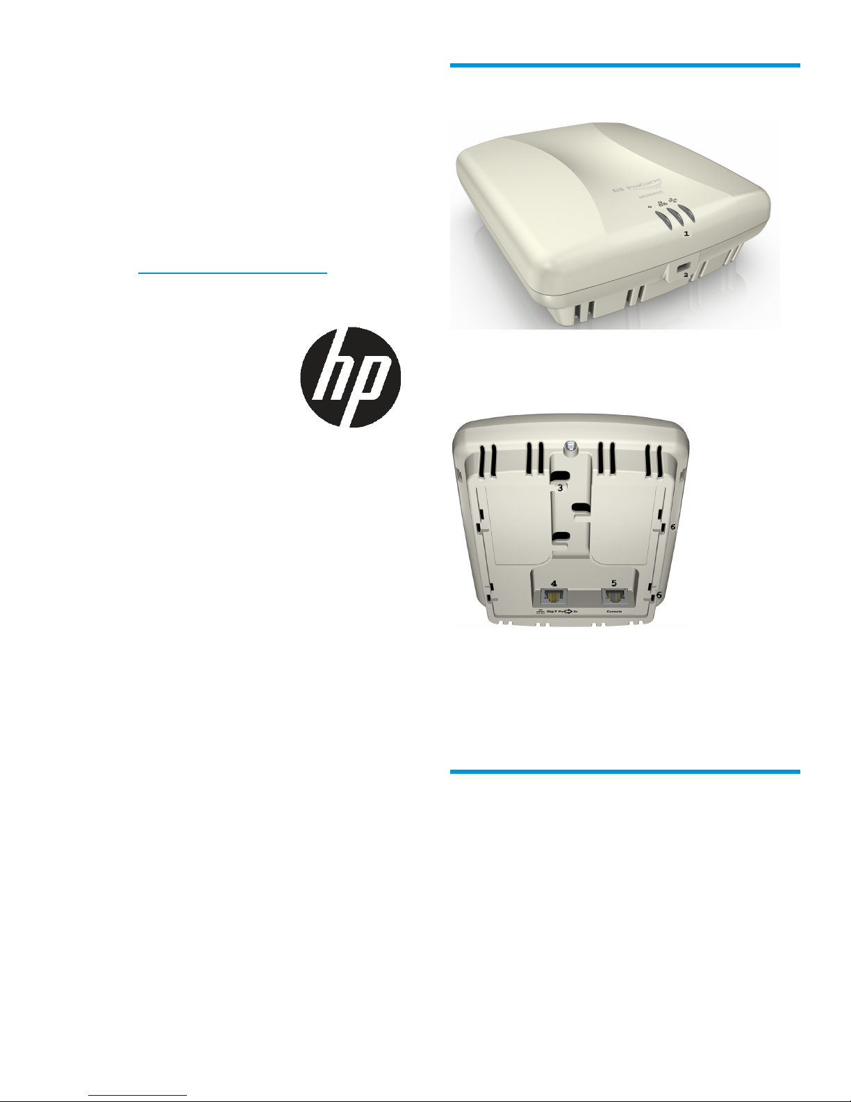
Hardware
1. Status LEDs
2. Lock tab
© Copyright 2015 Hewlett-Packard Development Company, L.P.
HP Part Number: 5998-7420
Published: February 2015
Edition: 1
*5998-7420*
3. Cable channel
4. Ethernet port (Port 1)
5. Console port
6. Mounting bracket tab slots
Package contents
MSM415, mounting bracket, two mounting screws
with wall anchors, and documentation.
Page 1
Page 2
Ports
Ethernet port (Port 1): Auto-sensing 10/100/1000
Base-T Ethernet port with RJ-45 connector. This port
supports Power over Ethernet (PoE) 802.3af.
Console port: Standard console (serial) port with an
RJ-45 connector.
Caution: Never connect the console port to an Ethernet
switch or PoE power source. This may damage the
sensor. Connect it only to other serial ports via an
RJ-45 to DB-9 adapter or equivalent.
Radios and Antennas
The sensor contains an integrated single 802.11n
Draft 2 compliant radio with an internal three-element,
dual-band MIMO antenna.
there is one wireless interface used for both 2.4 GHz
and 5 GHz, some states are overlapping.
DescriptionRadioEthernetPower
OnOnOn
OnOn
Flashing
quickly
The sensor is receiving power and
is working normally. The sensor is
also connected to the HP RF
Manager server.
• The sensor is performing
troubleshooting on
802.11b/g/n.
• The sensor is performing
troubleshooting on
802.11a/n.
• The sensor is performing
troubleshooting on 802.11a/n
and 802.11b/g/n.
• The sensor is performing
troubleshooting on 802.11a/n
and intrusion prevention on
802.11b/g/n.
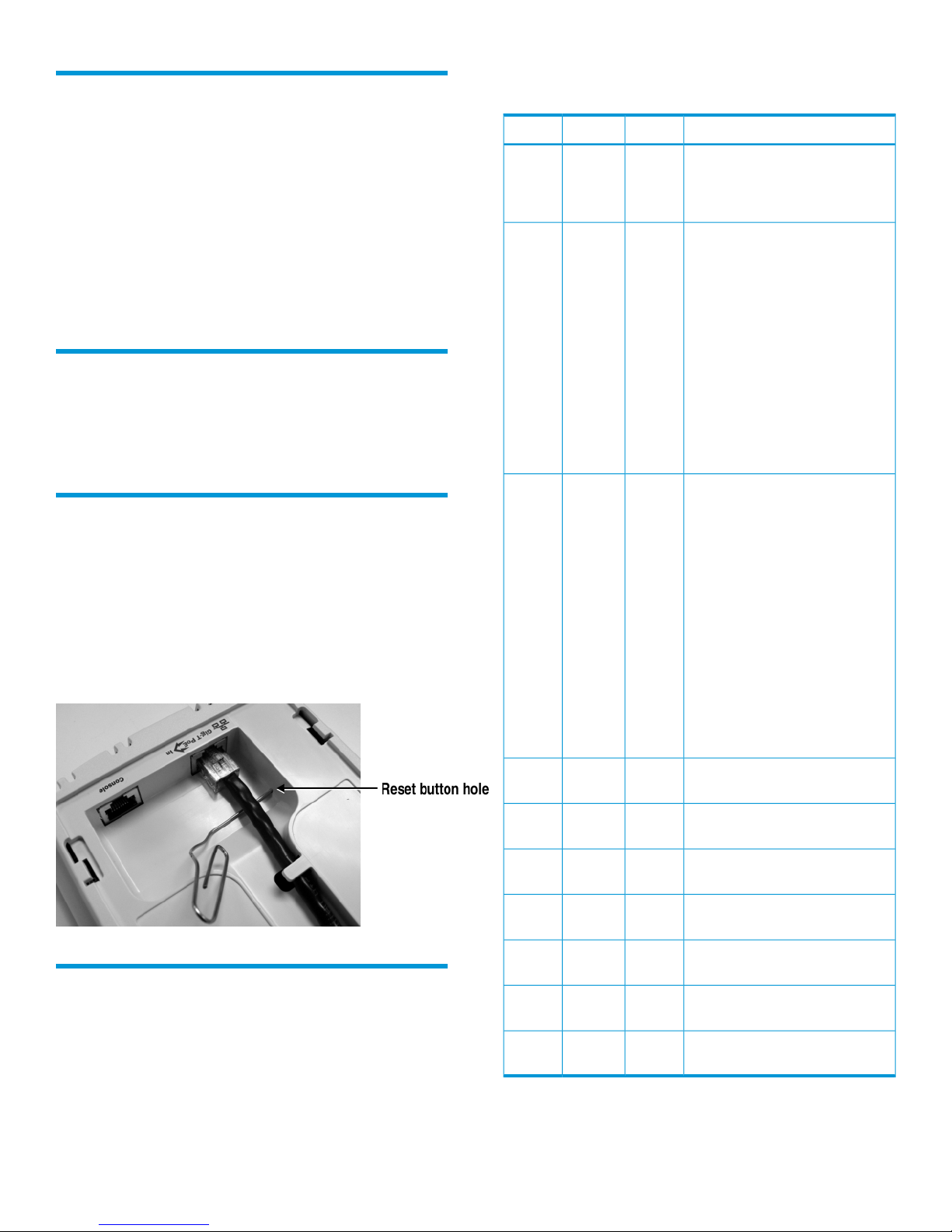
Reset button
The reset button is accessible via a hole on the bottom
of the sensor. To perform a reset, the unit must be
powered. Insert a paper clip under the cable and into
the reset button hole at the precise angle shown. Press
and quickly release the button to reset the sensor. To
reset the sensor to factory defaults, press the button
until the status LEDs flash three times, then release.
On
slowly
Flashing
quickly
Flashing
slowly
OnOn
Flashing
slowly
quickly
slowly
Flashing
slowly
slowly
—OnFlashing
—Flashing
—Flashing
• The sensor is performing
intrusion prevention on
802.11b/g/n.
• The sensor is performing
intrusion prevention on
802.11a/n.
• The sensor is performing
intrusion prevention on
802.11a/n and
troubleshooting on
802.11b/g/n.
• The sensor is performing
intrusion prevention on
802.11a/n and
802.11b/g/n.
The sensor upgrade is in progress.Flashing
The sensor is unable to get
Ethernet link.
The sensor did not receive a valid
IP address via the DHCP.
The sensor is unable to connect to
the RF Manager server.
Status LEDs
The following table indicates various MSM415 Sensor
states using the LEDs on the sensor device. Because
Page 2
slowly
slowly
On—Flashing
——Flashing
OffOffOff
There is an error on wireless
interface of the sensor.
The sensor is experiencing a
software error.
The sensor is not powered on or
it is in the process of starting up.
Page 3

Installing the sensor
Powering the sensor
Caution: Professional installation required. Prior to
installing or using the sensor, consult with a
professional installer trained in RF installation and
knowledgeable in local regulations including building
and wiring codes, safety, channel, power,
indoor/outdoor restrictions, and license requirements
for the intended country. It is the responsibility of the
end user to ensure that installation and use comply
with local safety and radio regulations.
Important: To prevent abuse and intrusion by
unauthorized personnel, it is extremely important to
install sensors such that it is difficult to unplug the
devices from the network or from the power outlet.
Cabling: You must use the appropriate cables, and
where applicable for your region, surge protection.
For compliance with EN55022 Class-B emissions
requirements use shielded Ethernet cables. Cables with
large boots may not insert into the RJ-45 connectors
properly. HP recommends that you do not use such
cables.
Plenum installation: The MSM415 and appropriate
cabling can be installed in a plenum (UL2043 rating).
The sensor should be installed with its top surface
facing the floor (similar orientation as in a ceiling
installation). However, it is left to a qualified installer
to determine how to install/secure the sensor in a
plenum in an appropriate and safe manner.
Plenum-rated cables and attachment hardware must
be used.
Safety: Take note of the following safety information
during installation.
The sensor can be powered by:
• A 10/100 or 10/100/1000 PoE-enabled switch.
Various PoE-enabled switches are available from
HP.
• An HP PoE 1-Port Power Injector (J9407A).
If the sensor will be powered by a user-supplied PoE
power injector, use only a gigabit-compatible power
injector. PoE injectors designed for 10/100 networks
only are not compatible with the sensor.
Mounting the bracket
The sensor can be mounted on a wall or a suspended
ceiling. In either case, the first step is to mount the
bracket, and the second step is to attach the sensor to
the bracket.
Mounting on a wall-mounted electrical box
1. Disconnect power and take any other needed
security precautions.
2. Remove the electrical box cover and any contents.
3. Pull the Ethernet cable down into the box, and
then through the hole in the bracket.
4. Hold the bracket against the box respecting the
UP indicator, and attach the bracket to the box
using appropriate countersunk screws.
• If your network covers an area served by more
than one power distribution system, be sure all
safety grounds are securely interconnected.
• Network cables may occasionally be subject to
hazardous transient voltages (caused by lightning
or disturbances in the electrical power grid).
• Handle exposed metal components of the network
with caution.
• The sensor is powered-on when connected to a
PoE power source.
• The sensor and all interconnected equipment must
be installed indoors within the same building
(except for outdoor models/antennas), including
all PoE-powered network connections as described
by Environment A of the IEEE 802.3af standard.
Mounting directly on a wall
1. Respecting the UP indicator on the bracket, hold
the bracket against the wall at the desired
position. Mark two holes for the screws (wall
anchors) and one hole in the cutout area of the
bracket for the Ethernet cable.
2. Drill two holes for the wall anchors, typically 4.7
mm (3/16 inch) in diameter.
Page 3
Page 4

3. Drill a hole for the Ethernet cable. Alternatively,
you can feed the Ethernet cable from above and
through the sensor cable channel.
4. Insert the anchors and tap them flush with the wall
surface.
5. Pull the Ethernet cable through the hole in the wall
and the hole in the bracket.
6. Screw the bracket to the wall.
Mounting on a suspended ceiling
The sensor can be mounted on a suspended ceiling
with user-supplied T-bar clips or the equivalent. Use a
clip stud size of 3.5 mm (#8-32) with a maximum
length of 11mm (7/16 inch).
Connect the sensor to the network
This procedure assumes that RF Manager is already
running on your network. Add the DNS entry
wifi-security-server on all DNS servers. This
entry should point to the IP address of the server.
To connect the sensor to the network:
1. Ensure that DHCP is running on the subnet to
which the sensor will be connected.
2. Connect one end of the Network Interface cable
to the Ethernet port (port 1) on the sensor.
3. Connect the other end of the Network Interface
cable to an Ethernet jack that is connected to the
desired subnet.
Important: If DHCP is not enabled on a subnet,
sensors cannot connect to that subnet with zero
configuration.
4. Wait two minutes.
5. Observe the status LEDs on the sensor. If all LEDs
glow green, the sensor is operational and
connected to the server.
6. Log on to the HP RF Manager server through SSH.
Run the get sensor list command.
1. Attach two T-bar clips (not supplied) to the bracket
as illustrated. The clips must be attached to the
smooth outer side of the bracket.
2. Attach the bracket to the suspended ceiling T-bar
at the desired mounting position.
3. When the bracket is firmly attached to the T-bar,
cut a hole in the ceiling through the bracket
opening for the Ethernet cable.
4. Pull the Ethernet cable through the hole in the
bracket.
Attach the sensor to the bracket
1. Connect the Ethernet cable to the sensor Ethernet
port. Push excess cable back into the hole.
2. Position the sensor against the bracket so that the
bracket tabs fit into the tab slots on the back of
the sensor. Push the sensor against the bracket
and then pull down firmly so that it snaps onto
the bracket.
3. Verify that the sensor is firmly anchored before
letting go of it.
4. Optionally, secure the sensor to an immovable
object with a Kensington-type cable lock using
the hole below the status LEDs.
You will see a list of all sensors that are
recognized by the server.
Important: The sensor is configured and ready to go.
Check the console to ensure that this sensor has been
detected.
Specifications
Dimensions
power rating
Temperature
humidity
Maximum
altitude
Connectors
H: 4.93 cm (1.94 inch), W: 13.18 cm (5.19
inch), D: 15.65 cm (6.16 inch)
0.33 kg (0.72 lb)Weight
PoE 802.3afDC input
8WMaximum
Operating: 0°C to 50°C (32°F to 122°F)
Non-operating: -40°C to 70°C (-40°F to 158°F)
Operating: 5% to 95% (non-condensing)Relative
Operating: 3048 m (10,000 ft)
nl
Non-operating: 4572 m (15,000 ft)
One 10/100/1000 Mbps RJ-45 autosensing
port
Page 4
Page 5

Safety
model number
Complies with EN60950-1/IEC 60950-1, CSA
22.2 No. 60950-1, UL 2043, and UL 60950-1
standards.
MRLBB-0802Regulatory
Related information
For more information, see HP RF Manager Installation
and Getting Started Guide, HP RF Manager for
VMware Installation Guide, and HP RF Manager and
Sensors Management and Configuration Guide
available at www.hp.com/support/manuals.
Other regulatory information
For important safety, environmental, and regulatory
information, see Safety and Compliance Information
for Server, Storage, Power, Networking, and Rack
Products, available at http://www.hp.com/support/
Safety-Compliance-EnterpriseProducts.
Belarus Kazakhstan Russia marking
Manufacturer and Local Representative Information
Manufacturer’s information:
• Hewlett-Packard Company, 3000 Hanover Street,
Palo Alto, California 94304, U.S.
Local Representative information Russian:
• HP Belarus: ИООО «Хьюлетт-Паккард Бел»,
220030, Беларусь, г. Минск, ул.
Интернациональная, 36-1, офис 722-723, тел.:
+375 (17) 392 28 18, факс: +375 (17) 392 28
21
• HP Kazakhstan: ТОО «Хьюлетт-Паккард (К),
050040, Казахстан, г. Алматы, Бостандыкский
район, ул. Тимирязева, 28В, 1 этаж, тел./факс:
+7 (727) 355 35 50, +7 (727) 355 35 51
• HP Russia: ЗАО “Хьюлетт-Паккард А.О.”,
125171, Россия, г. Москва, Ленинградское
шоссе, 16А, стр.3, тел/факс: +7 (495) 797 35
00, +7 (495) 287 89 05
Local Representative information Kazakh:
• HP Kazakhstan: ЖШС «Хьюлетт-Паккард (К)»,
Қазақстан, Алматы қ., Бостандық ауданы,
Тимирязев к-сі, 28В, тел./факс: +7 (727) 355
35 50, +7 (727) 355 35 51
Manufacturing Date – The manufacturing date is
included in the product serial number, CCYMPPPZZZ
(HP serial number format for this product). The
manufacturing date is indicated by YM in the serial
number, where Y indicates the year counting from
within each new decade, with 2010 as the starting
point, and M is the month when the unit was
manufactured. For example, 3A would indicate 3 for
2013 and A for the month of November. Following
this convention, 2010 is indicated by 0, 2011 by 1,
2012 by 2, 2013 by 3, and so forth. Months start at
1 for January, 2 for February, up to 9 for September.
0 (zero) is used for October, A for November, and B
for December.
Дата изготовления – Дата изготовления включена в
серийный номер изделия, CCYMPPPZZZ (формат
серийного номера HP для данного изделия). Дата
изготовления указана как YM в серийном номере,
где Y соответствует году с началом отсчета в каждом
новом десятилетии, начиная с 2010, а M
соответствует месяцу изготовления устройства.
Например, в обозначении 3A цифра 3 соответствует
2013 году, а A обозначает ноябрь. В соответствии
с данным принятым обозначением, 2010 год
указывается как 0, 2011 – как 1, 2012 – как 2,
2013 – как 3 и т. д. Месяцы обозначаются как 1
(январь), 2 (февраль) и т. д. до 9 (сентябрь). 0 (ноль)
обозначает октябрь, A обозначает ноябрь, а B
обозначает декабрь.
Жасалған күні – Жасалған күні CCYMPPPZZZ (осы
өнімге арналған HP сериялық нөмірінің пішімі)
пішіміндегі өнімнің сериялық нөмірінде қамтылады.
Жасалған күні сериялық нөмірдегі YM əріптерімен
көрсетіледі. Y əрпі 2010 жылдан басталатын жəне
əр он жылдан бастап есептелетін жылды көрсетеді
жəне M əрпі құрылғының жасалған айын білдіреді.
Мысалы, 3A таңбалары келісіні білдіреді: 3 – 2013
жылды жəне A қараша айын көрсетеді. Бұл əдіс
бойынша, 2010 жыл 0 санымен, 2011 жыл 1
санымен, 2012 жыл 2 санымен, 2013 жыл 3
санымен жəне т.т. көрсетіледі. Айларды 1 мен 9
аралығындағы сандар көрсетеді:1 саны қаңтар айы
үшін, 2 саны ақпан айы үшін жəне 9 саны қыркүйек
айы үшін. 0 (нөл) саны қазан айы үшін, A əрпі
қараша айы үшін жəне B əрпі желтоқсан айы үшін
қолданылады.
Page 5
Page 6

Documentation feedback
Send any errors, suggestions, or comments to
Documentation Feedback (docsfeedback@hp.com).
Page 6
 Loading...