

Page 1

ProCurve 5400zl Switches
Installation and Getting Started Guide
HP MSM313 / MSM323 Integrated Services Access Points Deployment Guide
HP MSM313/MSM323 Integrated Services Access Points
Deployment Guide
Page 2

Page 3

HP MSM313/MSM323 Integrated
Services Access Points
Deployment Guide
Page 4

© Copyright 2010 Hewlett-Packard Development Company, L.P. The information contained herein
is subject to change without notice.
This document contains proprietary information, which is protected by copyright. No part of this
document may be photocopied, reproduced, or translated into another language without the prior
written consent of Hewlett-Packard.
Publication Number
5998-0453
July 2010
Trademark Credits
Windows NT®, Windows®, and MS Windows® are US registered trademarks of Microsoft
Corporation.
Disclaimer
HEWLETT-PACKARD COMPANY MAKES NO WARRANTY OF ANY KIND WITH REGARD TO
THIS MATERIAL, INCLUDING, BUT NOT LIMITED TO, THE IMPLIED WARRANTIES OF
MERCHANTABILITY AND FITNESS FOR A PARTICULAR PURPOSE. Hewlett-Packard shall not
be liable for errors contained herein or for incidental or consequential damages in connection with
the furnishing, performance, or use of this material.
The only warranties for Hewlett-Packard products and services are set forth in the express
warranty statements accompanying such products and services. Nothing herein should be
construed as constituting an additional warranty. Hewlett-Packard shall not be liable for technical or
editorial errors or omissions contained herein.
Hewlett-Packard assumes no responsibility for the use or reliability of its software on equipment
that is not furnished by Hewlett-Packard.
Warranty
See the Customer Support/Warranty booklet included with the product. A copy of the specific
warranty terms applicable to your Hewlett-Packard products and replacement parts can be
obtained from your Hewlett-Packard Sales and Service Office or authorized dealer.
Open Source Software Acknowledgement Statement
This software incorporates open source components that are governed by the GNU General Public
License (GPL), version 2. In accordance with this license, Hewlett-Packard will make available a
complete, machine-readable copy of the source code components covered by the GNU GPL upon
receipt of a written request. Send a request to:
Hewlett-Packard Company, L.P. GNU GPL Source Code
Attn: HP Support
Roseville, CA 95747 USA
www.hp.com
Page 5

HP MSM313/MSM323 Deployment Guide 3 Contents
Contents
Chapter 1
Introduction 7
About this guide................................................................................8
Products covered........................................................................8
Important terms..........................................................................8
Conventions ................................................................................8
Contacting support .....................................................................9
Online documentation .................................................................9
Chapter 2
Public/guest networks 11
Introduction ....................................................................................12
Scenario 1a: Hotspot in a box .........................................................13
How it works.............................................................................13
Configuration road map ............................................................13
A. Install the service controller............................................13
B. Configure the wireless network ......................................14
C. Configure the Internet connection ..................................14
D. Define the list of users....................................................14
E. Test the public access interface ......................................14
Scenario 1b: Hotspot with custom interface ...................................16
How it works.............................................................................16
Configuration road map ............................................................16
A. Configure the Internet port .............................................16
Examples ..................................................................................17
A. Customize the login page and logo.................................17
B. Test the public access interface ......................................18
Scenario 1c: Hotspot with satellites and roaming ...........................19
How it works.............................................................................19
Configuration road map ............................................................19
A. Install the APs.................................................................19
B. Switch the APs to autonomous mode .............................20
C. Configure the wireless network ......................................20
D. Set the shared secret on the service controller...............20
E. Configure the connection to the service controller on the
APs .....................................................................................20
Scenario 1d: Hotspot with layer 2 encryption .................................21
How it works.............................................................................21
Configuration road map ............................................................21
A. Create VSCs on the APs..................................................21
B. Create VSCs on the service controller.............................22
Scenario 2a: Hotspot with RADIUS authentication..........................24
How it works.............................................................................24
Configuration road map ............................................................24
A. On the RADIUS server ....................................................24
B. Install the service controller............................................24
C. Configure the wireless network ......................................25
D. Configure the Internet port .............................................25
E. Create a RADIUS profile ..................................................25
F. Enable RADIUS authentication of users ...........................25
G. Test the public access interface......................................25
Scenario 2b: Hotspot with custom interface (via RADIUS server) ..27
How it works.............................................................................27
Configuration road map ............................................................27
A. Customize the login page and logo.................................27
B. Define attributes on the RADIUS server..........................28
C. Configure the service controller to retrieve attributes from
the RADIUS server ..............................................................28
D. Test the public access interface......................................29
Scenario 2c: Hotspot with satellites and roaming (via RADIUS server)
30
How it works.............................................................................30
Configuration road map ............................................................30
A. Install the APs.................................................................30
B. Switch the APs to autonomous mode.............................30
C. Configure the wireless network ......................................31
D. Set the shared secret on the service controller...............31
E. Configure the connection to the service controller on the
APs .....................................................................................31
Scenario 2d: Hotspot with layer 2 security (AAA server) ................32
How it works.............................................................................32
Configuration road map ............................................................32
A. Create VSCs on the APs..................................................32
B. Create VSCs on the service controller.............................33
Scenario 2e: Using two radios to support A+B+G traffic .................35
How it works.............................................................................35
Network topology................................................................35
Configuration road map ............................................................35
A. Configure radio 2 ............................................................35
B. Configure VSC profiles ...................................................35
Scenario 3: Shared hotspot for public and private traffic ................36
How it works.............................................................................36
Configuration road map ............................................................37
A. Define settings on the RADIUS servers ..........................37
B. Install the service controller and AP ...............................37
C. Switch the AP to autonomous mode ..............................37
Configure the service controller..........................................37
A. Configure the Internet port .............................................37
B. Create two RADIUS profiles............................................37
C. Create VLANs..................................................................38
D. Create VSCs....................................................................38
E. Set the shared secret ......................................................39
Configure the AP.................................................................39
A. Create VSCs....................................................................39
B. Configure the connection to the service controller .........40
Scenario 4: Delivering custom HTML pages using VLANs..............41
How it works............................................................................41
Configuration road map ............................................................42
A. On the RADIUS server ....................................................42
B. Install the service controller and the APs........................42
C. Switch the APs to autonomous mode.............................42
D. Configure the wireless network ......................................42
Configure the service controller..........................................42
A. Configure the Internet port .............................................42
B. Create a RADIUS profile..................................................43
C. Configure the service controller to retrieve attributes from
the RADIUS server ..............................................................43
D. Create VLANs .................................................................43
E. Create VSCs ....................................................................44
F. Set the shared secret .......................................................45
Configure the APs ...............................................................45
A. Set static addressing and management VLAN ................45
B. Configure management VLAN.........................................45
C. Configure a VSC .............................................................46
D. Configure the connection to the service controller .........46
Scenario 5: Custom HTML pages on each AP .................................47
How it works.............................................................................47
Configuration road map ............................................................48
A. Install the service controller and the APs........................48
B. Switch the APs to autonomous mode.............................48
C. Create the custom web pages on the web server............48
Configure the APs ...............................................................49
Page 6

HP MSM313/MSM323 Deployment Guide 4 Contents
A. Configure the wireless network ......................................49
B. Configure the location-aware group name ......................49
C. Configure the connection to the service controller on the
APs .....................................................................................49
Configure the service controller ..........................................50
A. Configure the Internet port .............................................50
B. Configure attributes to activate the customized pages....50
C. Define the list of condo tenants ......................................50
D. Set the shared secret on the service controller...............50
E. Setup location aware.......................................................51
F. Using the public access interface ....................................51
Scenario 6: Multi-site installation (distributed architecture)............52
How it works.............................................................................52
Configuration road map ............................................................53
A. On the RADIUS server ....................................................53
B. Install the service controllers..........................................53
C. Configure the Internet port .............................................53
D. Configure the wireless network ......................................53
E. Create a RADIUS profile ..................................................53
F. Configure the VSC ...........................................................53
G. Customize the login page and logo.................................54
H. Define attributes on the RADIUS server..........................54
I. Configure the service controller to retrieve attributes from
the RADIUS server ..............................................................55
J. Using the public access interface ....................................55
Scenario 7: Multi-site installation (centralized architecture)............56
How it works.............................................................................56
Configuration road map ............................................................56
A. Install the service controllers..........................................56
B. Configure the Internet port .............................................57
C. Configure the wireless network ......................................57
D. Configure the GRE tunnels .............................................57
E. Configure the VSC...........................................................57
A. Configure addressing......................................................70
B. Configure the radios .......................................................71
C. Configure the local mesh links........................................71
D. Configure the connection to the service controller on the
APs .....................................................................................71
E. Create VSCs on the APs..................................................72
Service controller configuration ..........................................73
A. Configure the Internet port .............................................73
B. Set the shared secret on the service controller...............73
C. Create a RADIUS profile..................................................73
D. Create VSCs on the service controller ............................73
E. Configure the radios .......................................................75
F. Configure the local mesh link ..........................................75
Chapter 3
Local mesh deployment 59
Scenario 1a: Dynamic local mesh ...................................................60
How it works.............................................................................60
Configuration road map ............................................................61
A. Install the APs and the service controller........................61
B. Switch the APs to autonomous mode .............................61
AP configuration .................................................................61
A. Configure addressing......................................................61
B. Configure the radios .......................................................62
C. Configure the local mesh links ........................................62
D. Configure the connection to the service controller on the
APs .....................................................................................63
E. Create VSCs on the APs ..................................................63
Service controller configuration..........................................64
A. Configure the Internet port .............................................64
B. Set the shared secret on the service controller ...............64
C. Create a RADIUS profile..................................................64
D. Create VSCs on the service controller ............................64
E. Configure the radios .......................................................66
F. Configure the local mesh link ..........................................66
Scenario 1b: Dynamic local mesh with load balancing....................67
How it works.............................................................................67
Configuration road map ............................................................68
A. Install and configure the AP D and AP E .........................68
B. Install and configure service controller 2........................68
Scenario 2: Creating a self-healing network....................................69
How it works.............................................................................69
Configuration road map ............................................................70
A. Install the APs.................................................................70
B. Switch the APs to autonomous mode .............................70
AP configuration .................................................................70
Page 7

Chapter 1: Introduction
Contents
About this guide - - - - - - - - - - - - - - - - - - - - - - - - - - - - - 6
Contacting support - - - - - - - - - - - - - - - - - - - - - - - - - - - - 7
1
Introduction
Online documentation - - - - - - - - - - - - - - - - - - - - - - - - - - 7
Page 8

HP MSM313/MSM323 Deployment Guide 6 1 Introduction
About this guide
This guide contains detailed scenarios for using HP MSM313/MSM323 Integrated Services Access
Points and HP MSM Access Points in a wide range of applications.
Although detailed configuration steps are provided for each scenario, this guide does not
cover the basic procedures for operating and configuring HP ProCurve mobility devices.
This information can be found in the Management and Configuration Guides for each
product. You should be familiar with this information before you attempt to use the
scenarios in this guide.
Products covered
This guide covers the following products:
• MSM313, MSM313-R, MSM323, MSM323-R
• MSM335, MSM310, MSM310-R, MSM320, MSM320-R
Important terms
The following terms are used in this guide.
Term Description
AP Refers only to HP MSM Access Points: MSM335, MSM310,
service controller Refers to the HP MSM Integrated Services Access Points,
local mesh In previous versions of the management tool and all former
Conventions
Management tool
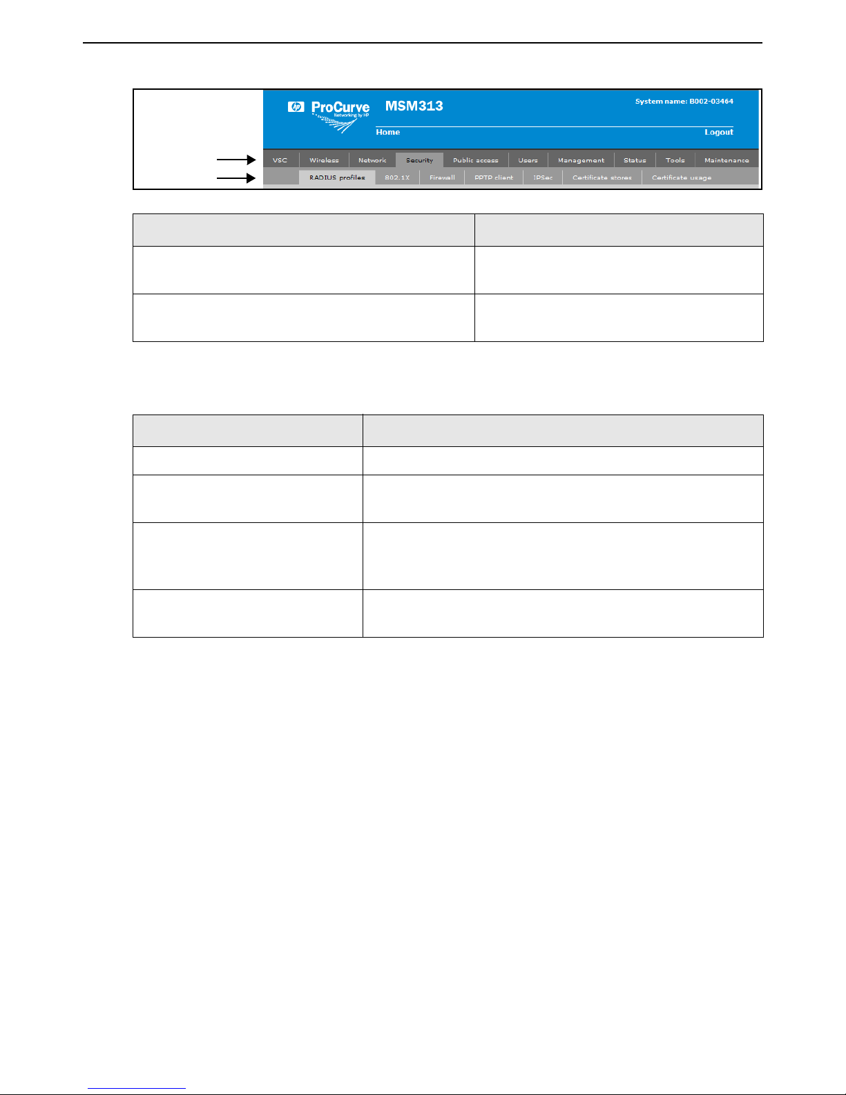
This guide uses specific syntax when directing you to interact with the management tool user
interface. Refer to this image for identification of key user-interface elements and then the table
below showing example instructions:
MSM310-R, MSM320, and MSM320-R.
comprised of the MSM313, MSM313-R, MSM323, and
MSM323-R.
documentation, “local mesh” was known as “DWDS” (dynamic
wireless distribution system).
Page 9
HP MSM313/MSM323 Deployment Guide 71 Introduction
Main menu
Sub-menu
Example directions in this guide What to do in the user interface
Select Security > RADIUS profiles. On the main menu select Security and then
select RADIUS profiles on the sub-menu.
For Password specify secret22. In the field Password enter the text
secret22 exactly as shown.
Commands and program listings
Monospaced text identifies commands, and program listings as follows:
Example Description
use-access-list
ip_address
ssl-certificate=URL [%s]
[ONE | TWO]
Contacting support
The HP Web site, www.hp.com/networking/support provides up-to-date support information.
Additionally, your HP-authorized network reseller can provide you with assistance, both with
services that they offer and with services offered by HP.
Online documentation
The latest documentation is available on the HP Support Web page at:
www.hp.com/networking/support.
Command name. Specify it as shown.
Items in italics are parameters for which you must supply a
value.
Items enclosed in square brackets are optional. You can
either include them or not. Do not include the brackets. In
this example you can either include the “%s” or omit it.
Items separated by a vertical line indicate a choice. Specify
only one of the items. Do not include the vertical line.
Page 10

HP MSM313/MSM323 Deployment Guide 8 1 Introduction
Page 11

Chapter 2: Public/guest networks
Public/guest networks
Contents
Introduction - - - - - - - - - - - - - - - - - - - - - - - - - - - - - - - 10
Scenario 1a: Hotspot in a box- - - - - - - - - - - - - - - - - - - - - - - 11
2
Scenario 1b: Hotspot with custom interface - - - - - - - - - - - - - - - - 14
Scenario 1c: Hotspot with satellites and roaming - - - - - - - - - - - - - 17
Scenario 1d: Hotspot with layer 2 encryption - - - - - - - - - - - - - - - 19
Scenario 2a: Hotspot with RADIUS authentication - - - - - - - - - - - - - 22
Scenario 2b: Hotspot with custom interface (via RADIUS server) - - - - - 25
Scenario 2c: Hotspot with satellites and roaming (via RADIUS server) - - - 28
Scenario 2d: Hotspot with layer 2 security (AAA server) - - - - - - - - - - 30
Scenario 2e: Using two radios to support A+B+G traffic - - - - - - - - - - 33
Scenario 3: Shared hotspot for public and private traffic - - - - - - - - - - 34
Scenario 4: Delivering custom HTML pages using VLANs - - - - - - - - - 39
Scenario 5: Custom HTML pages on each AP- - - - - - - - - - - - - - - 45
Scenario 6: Multi-site installation (distributed architecture) - - - - - - - - - 50
Scenario 7: Multi-site installation (centralized architecture)- - - - - - - - - 54
Page 12

HP MSM313/MSM323 Deployment Guide 10 2 Public/guest networks
Introduction
This chapter presents a variety of scenarios for public/guest network access deployments using
MSM313/MSM323 Integrated Services Access Points operating alone or with one or more MSM
Access Points.
Note: In this chapter, the MSM313 and MSM323 Integrated Services Access Points are
often referred to as "service controller" and MSM Access Points are often referred to
as "AP."
Page 13

HP MSM313/MSM323 Deployment Guide 11 2 Public/guest networks
P
U
B
L
I
C
W
L
A
N
1.4
1.5
1.6
1.7
Service
controller
LAN
LAN port
Internet port
192.168.1.0
1.2 1.3
Management
station
Modem
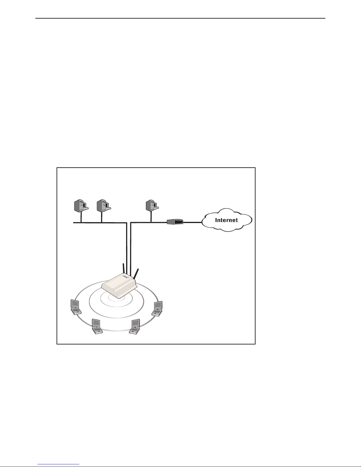
Scenario 1a: Hotspot in a box
This scenario shows you how to quickly deploy and test the service controller without installing a
RADIUS server. Instead, user authentication is handled locally.
How it works
In this scenario, a single service controller is installed to provide a wireless network and access to
the Internet. The service controller is connected to the Internet by way of a broadband modem, and
the Internet connection is protected by the service controller’s firewall and NAT features (which are
enabled by default).
service controller acts as the DHCP server on both the wireless and wired networks which are
bridged together on subnet 192.168.1.0.
User authentication is handled locally by the service controller and accounts are created on the
A local area network is connected to the service controller’s LAN port to support wired users. The
service controller for each user. There is no support for accounting.
The default public access interface resident on the service controller is used to control user logins
and manage their sessions.
The default VSC is used on the service controller, which means that users connect with the SSID
“HP ProCurve”.
Configuration road map
A. Install the service controller
1. Install the service controller as described in its Quickstart guide.
2. Connect the Internet port to a broadband modem and then restart the modem.
Page 14
HP MSM313/MSM323 Deployment Guide 12 2 Public/guest networks
3. Connect the LAN port to the local area network.
4. Start the management tool.
B. Configure the wireless network
By default the service controller is configured to:
• automatically choose the best operating channel (frequency)
• support 802.11b/g clients
• create a wireless network named HP ProCurve
There is no need to change these settings for this scenario.
C. Configure the Internet connection
1. Select Network > Ports > Internet port.
2. Select the addressing option supported by your ISP and click Configure.
3. Define all settings as required by your ISP.
D. Define the list of users
1. Select Users > Users.
2. Add usernames and passwords for all users.
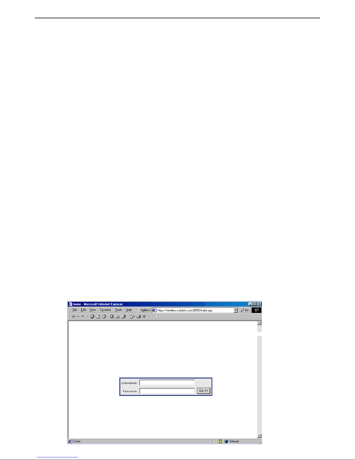
E. Test the public access interface
To test your installation, use a wireless client station to log onto the public access interface. The
wireless client should be configured as a DHCP client.
1. Start the client station’s web browser and try to connect to a web site on the Internet.
2. The service controller will intercept the URL and display the Login page. (Depending on the
type of certificate that is installed on the service controller, you may see a security warning first.
Accept the certificate to continue.)
Page 15
HP MSM313/MSM323 Deployment Guide 13 2 Public/guest networks
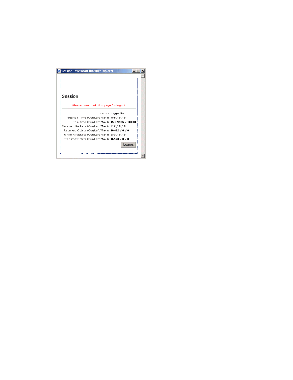
3. Specify a valid user name and password and click Go.
4. The Session page should open and you are automatically redirected to the web site you
originally requested.
Note: The session page may not appear if your web browser has a popup blocker.
Page 16
HP MSM313/MSM323 Deployment Guide 14 2 Public/guest networks
P
U
B
L
I
C
W
L
A
N
1.4
1.5
1.6
1.7
Service
controller
LAN port
Internet port
192.168.1.0
1.2 1.3
Router
Firewall
Web server
LAN B
192.168.5.0
5.1
5.21.1
LAN A
Management
station
Scenario 1b: Hotspot with custom interface
This scenario adds custom settings to the default public access interface used in
Scenario 1a.
This scenario illustrates how to customize the operation of the public access interface by defining
custom web pages on a third-party web server and loading them onto the service controller.
How it works
In this scenario, a web server is used to store custom pages for the public access interface. The
service controller loads these pages instead of using the default pages.
In this version, the web server is located on local LAN B, however it could also be located on the
Internet.
The router is also the DHCP server for LAN B, operating on subnet 192.168.5.0. The service
controller’s Internet port is set to operate as a DHCP client.
Configuration road map
Note: Start with the configuration defined in Scenario 1a.
A. Configure the Internet port
1. Select Network > Ports > Internet port.
2. Select DHCP Client and click Save.
Page 17

HP MSM313/MSM323 Deployment Guide 15 2 Public/guest networks
Examples
Sample public access files are referenced in this document. To get these files, go to the HP support
Website at: www.hp.com/networking/support and select the option needed to get to the MSM
product documentation page (ProCurve).
Select the documentation page for MSM313 and MSM323 Integrated Services Access Points. You
will find the Public Access Examples zip near the other MSM313/MSM323 documentation.
Download the zip file and extract its content to a folder on your computer.
A. Customize the login page and logo
To create the pages:
1. Create a folder called newpages on the web server.
2. Create a file called logo.gif that contains your logo and place it in the newpages folder
(recommended size less than 20K). This same image file is shared by all pages.
3. Copy the following files from the MSM Public Access Examples zip file to the newpages
folder on the web server.
• login.html
• transport.html
• session.html
• fail.html
4. Edit login.html to meet the requirements of your site, keeping the following restrictions in
mind:
• Do not alter the ID tags “<!-- Colubris -->” & “<!-- Custom -->” located at the top of the page.
• Do not alter any existing JavaScript code.
5. On the service controller, select Public access > Attributes
6. Assuming that the web server is at the address 192.168.5.1, Add the following attributes to the
Configured attributes table:
login-page=192.168.5.1/newpages/login.html
transport-page=192.168.5.1/newpages/transport.html
session-page=192.168.5.1/newpages/session.html
fail-page=192.168.5.1/newpages/fail.html
logo=192.168.5.1/newpages/logo.gif
Note: The pages must be changed as a group. So even if you did not change all the
pages, you must still supply new files for all the pages and define all attributes as
shown.
Page 18

HP MSM313/MSM323 Deployment Guide 16 2 Public/guest networks
7. Determine if the pages were successfully loaded by selecting: Tools > System log.
If the pages were loaded successfully, the log will contain the message:
LOGINFO("%d update(s) to internal HTML pages/logo.\n", updates);
If the pages could not be loaded, the log will contain the message:
LOGWARNING( gettext ("At least one required internal page was not
retrieved - Keeping previous set of internal pages.") );
B. Test the public access interface
To test your installation, use a wireless client station to log onto the public access interface. The
wireless client should be configured as a DHCP client.)
1. Start the client station’s web browser and try to connect to a web site on the Internet.
2. The service controller will intercept the URL and display the Login page. (Depending on the
type of certificate that is installed on the service controller, you may see a security warning first.
Accept the certificate to continue.)
3. To login, specify a valid user name and password. The Session page should open and you
automatically redirected to the web site you originally requested.
Note: The session page may not appear if your web browser has a popup blocker.
Page 19
HP MSM313/MSM323 Deployment Guide 17 2 Public/guest networks
P
U
B
L
I
C
W
L
A
N
P
U
B
L
I
C
W
L
A
N
AP AP
192.168.1.0
LAN port
Internet port
1.2 1.3
P
U
B
L
I
C
W
L
A
N
1.4
1.5
1.6
1.7
Router
Firewall
Web server
LAN B
192.168.5.0
5.1
5.21.1
LAN A
1.81.9
Service
controller
Management
station
1.10
1.11
1.12
1.13
1.14
1.15 1.16
1.17
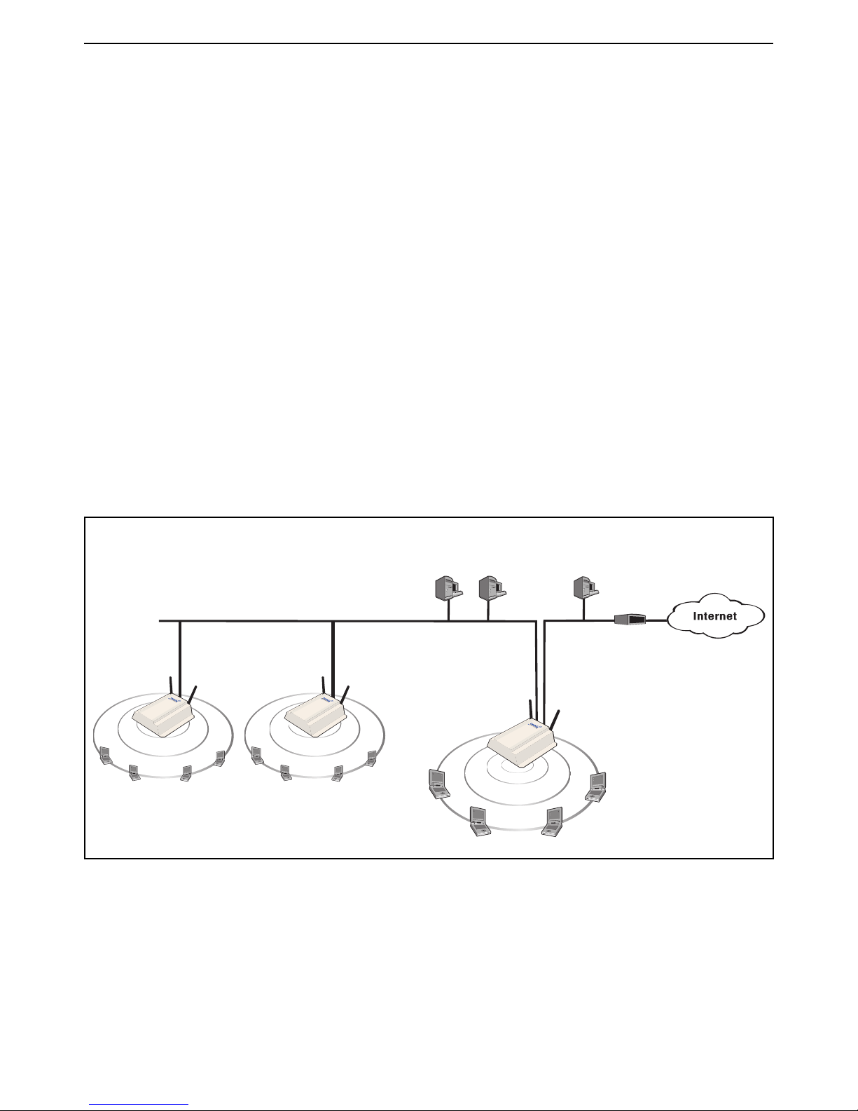
Scenario 1c: Hotspot with satellites and roaming
This scenario adds two APs to extend the wireless network in Scenario 1b.
This scenario adds two autonomous APs to extend the reach of the public access network created
by a service controller.
How it works
In this scenario, two autonomous APs are connected to a service controller to provide multiple
wireless cells for a large physical location.
Users can log into the public access network at any location and can roam between APs without
losing their connection.
By default, each AP is configured as a DHCP client and obtains its address from the service
controller, which by default is configured as the DHCP server.
User authentication is handled locally by the service controller, using accounts created on the
service controller for each user. There is no support for accounting.
The following diagram illustrates how the topology described in Scenario 1b can be modified to
support additional APs and roaming.
Configuration road map
Note: Start with the configuration defined in Scenario 1b.
A. Install the APs
Install the APs as described in the appropriate Quickstart guide.
Page 20

HP MSM313/MSM323 Deployment Guide 18 2 Public/guest networks
B. Switch the APs to autonomous mode
By default the APs are configured to operate in controlled mode. Switch them to autonomous mode
as follows:
1. Start the AP management tool and login.
2. On the home page click Switch to Autonomous Mode. The AP will restart.
3. Before you connect each AP to the LAN, start the management tool and configure each AP as
described in the sections that follow.
C. Configure the wireless network
By default the APs are configured to:
• support 802.11b/g clients
• automatically choose the best operating channel (frequency)
• create a wireless network named HP ProCurve
There is no need to change these settings for this scenario.
D. Set the shared secret on the service controller
1. Select Public access > Access control.
2. In the Access controller shared secret box, set Shared secret and Confirm shared secret
to a unique string. For example: xr2t56. This password will be used by the APs to connect to
the service controller when they send authentication requests.
3. Click Save.
E. Configure the connection to the service controller on the APs
Each AP will use the service controller to authenticate user logins. Do the following on each AP.
1. Select VSC > Profiles.
2. Click the HP ProCurve profile to edit it.
3. In the General box, select the Use HP ProCurve MSM controller check box.
4. Click Save.
5. Select Security > Access controller
6. Set the Access controller shared secret to match the secret set on the service controller.
7. Click Save.
Note: By default the AP is set up to use the default gateway assigned by DHCP as the
service controller. Do not change this setting.
Page 21
HP MSM313/MSM323 Deployment Guide 19 2 Public/guest networks
192.168.1.0
LAN port
Internet port
1.2 1.3
Router
Firewall
Web server
LAN B
192.168.5.0
5.1
5.21.1
LAN A
1.41.41.5
AP
SSID
WPA
SSID
WEP
Service
controller
SSID
WPA
SSID
WEP
AP
SSID
WPA
SSID
WEP
Management
tool
Scenario 1d: Hotspot with layer 2 encryption
This scenario adds support for wireless encryption to scenario 1c.
This scenario shows how to enable wireless protection to safeguard transmissions against
eavesdropping.
How it works
This scenario creates two virtual service communities (VSCs) on each device. One VSC provides
support for WPA (with preshared key) and the other provides support for WEP.
To connect with the wireless network, users must select the SSID of the VSC that matches the
option that they want to use. Roaming is supported, since the same VSCs are defined on all APs.
Configuration road map
Note: Start with the configuration defined in Scenario 1c.
A. Create VSCs on the APs
Follow this procedure to create three virtual service communities on all APs.
1. Select VSC > Profiles.
2. On the Virtual Service Communities page, click the HP ProCurve profile to edit it.
3. On the Add/Edit Virtual Service Community page:
• Under General, set Name to None.
• Under General, select the Use HP ProCurve MSM controller check box.
• Under Virtual AP, set WLAN name (SSID) to None.
• Click Save.
Page 22

HP MSM313/MSM323 Deployment Guide 20 2 Public/guest networks
4. On the Virtual Service Communities page, click Add New Profile.
5. On the Add/Edit Virtual Service Community page:
• Under General, set Name to WEP.
• Under General, select the Use HP ProCurve MSM controller check box.
• Under Virtual AP, set WLAN name (SSID) to WEP.
• Under Wireless protection:
• Select the checkbox and choose WEP.
• For Key, specify 13 ASCII characters as the key.
• Click Save.
6. On the Virtual Service Communities page, click Add New Profile.
7. On the Add/Edit Virtual Service Community page:
• Under General, set Name to WPA.
• Under General, select the Use HP ProCurve MSM controller check box.
• Under Virtual AP, set WLAN name (SSID) to WPA.
• Under Wireless protection:
• Select the checkbox and leave the default setting of WPA.
• For Mode, select WPA (TKIP) or WPA2 (AES/CCMP).
• For Key source, select Preshared key.
• For Key and Confirm key, set a unique key value.
• Click Save.
B. Create VSCs on the service controller
Follow this procedure to create virtual service communities on the service controller that match
each VSC you configured on the APs:
1. Select VSC > Profiles.
2. On the Virtual Service Communities page, click the HP ProCurve profile to edit it.
3. On the Add/Edit Virtual Service Community page:
• Under General, set Name to None.
• Under Virtual AP, set WLAN name (SSID) to None.
• Click Save.
4. On the Virtual Service Communities page, click Add New Profile.
Page 23

HP MSM313/MSM323 Deployment Guide 21 2 Public/guest networks
5. On the Add/Edit Virtual Service Community page:
• Under General, set Name to WEP.
• Under Virtual AP, set WLAN name (SSID) to WEP.
• Under Wireless protection:
• Select the checkbox and choose WEP.
• For Key, specify the same 13 ASCII characters you defined on the APs.
• Click Save.
6. On the Virtual Service Communities page, click Add New Profile.
7. On the Add/Edit Virtual Service Community page:
• Under General, set Name to WPA.
• Under Virtual AP, set WLAN name (SSID) to WPA.
• Under Wireless protection:
• Select the checkbox and leave the default setting of WPA.
• For Mode, select WPA (TKIP) or WPA2 (AES/CCMP).
• For Key source, select Preshared key.
• For Key and Confirm key, set the same unique key value you defined on the APs.
• Click Save.
Page 24
HP MSM313/MSM323 Deployment Guide 22 2 Public/guest networks
P
U
B
L
I
C
W
L
A
N
1.4
1.5
1.6
1.7
Service
controller
LAN port
Internet port
192.168.1.0
1.2 1.3
Router
Firewall
RADIUS server
LAN B
192.168.5.0
5.1
5.21.1
LAN A
Management
station
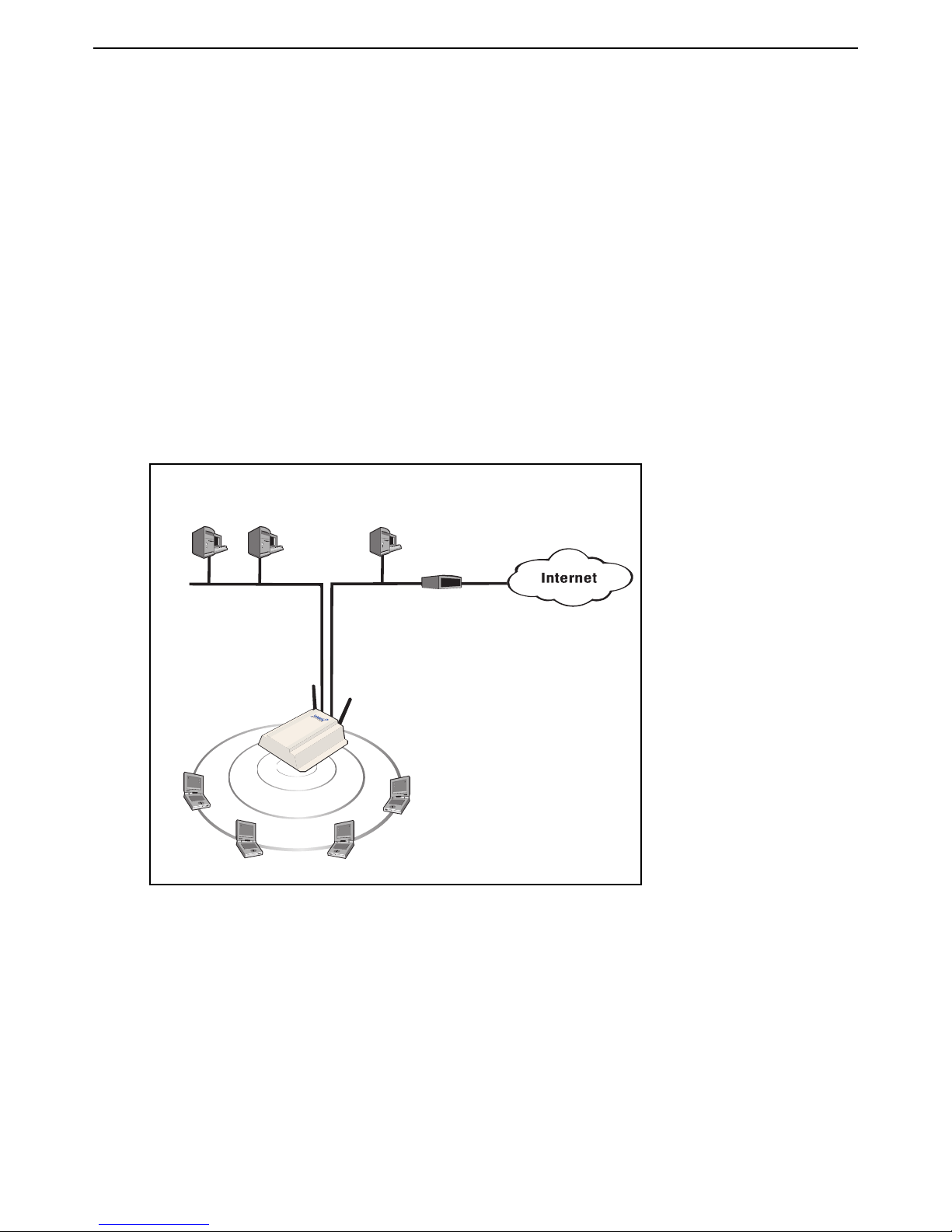
Scenario 2a: Hotspot with RADIUS authentication
This installation shows you how to create a public access network using an AAA (authentication,
administration, accounting) RADIUS server to handle user authentication.
How it works
In this scenario a single service controller is installed to provide a wireless network and access to
the Internet.
A local area network is connected to the service controller’s LAN port to support wired users. The
service controller acts as the DHCP server on both the wireless and wired networks which are
bridged together on subnet 192.168.1.0.
A RADIUS server provides services for user authentication and accounting. The RADIUS server is
located on local LAN B along with a router/firewall which handles the connection to the Internet and
acts as a DHCP server on LAN B.
Configuration road map
A. On the RADIUS server
Define RADIUS accounts for all users that will use the public access network.
B. Install the service controller
1. Install the service controller as described in its Quickstart guide.
2. Connect the Internet port to LAN B.
3. Connect the LAN port to the LAN A.
4. Start the management tool.
Page 25

HP MSM313/MSM323 Deployment Guide 23 2 Public/guest networks
C. Configure the wireless network
By default the service controller is configured to:
• support 802.11b/g clients
• automatically choose the best operating channel (frequency)
• create a wireless network named HP ProCurve
There is no need to change these settings for this scenario.
D. Configure the Internet port
1. Select Network > Ports > Internet port.
2. Select DHCP Client and click Save.
E. Create a RADIUS profile
1. Select Security > RADIUS profiles.
2. Click Add New Profile.
3. In the Profile name box, assign RADIUS Profile 1 to the new profile.
4. In the Settings box, use the defaults except for Authentication method which must match the
method supported by the RADIUS server.
5. In the Primary RADIUS server box, specify the address of the RADIUS server and the secret
the service controller will use to login.
F. Enable RADIUS authentication of users
1. Select VSC > Profiles.
2. On the Virtual Service Communities page, click the HP ProCurve profile to edit it.
3. On the Add/Edit Virtual Service Community page:
• Under HTML-based user logins,:
• Clear the Local authentication checkbox.
• Select the RADIUS authentication checkbox.
• For RADIUS profile, select RADIUS Profile 1.
• Select the RADIUS accounting checkbox.
• Click Save.
G. Test the public access interface
To test your installation, use a wireless client station to log onto the public access interface. The
wireless client should be configured as a DHCP client.)
1. Start the client station’s web browser and try to connect to a web site on the Internet.
Page 26

HP MSM313/MSM323 Deployment Guide 24 2 Public/guest networks
2. The service controller will intercept the URL and display the Login page. (Depending on the
type of certificate that is installed on the service controller, you may see a security warning first.
Accept the certificate to continue.)
3. Specify a valid user name and password and click Go.
4. The Session page should open and you automatically redirected to the web site you originally
requested.
Note: The session page may not appear if your web browser has a popup blocker.
Page 27

HP MSM313/MSM323 Deployment Guide 25 2 Public/guest networks
P
U
B
L
I
C
W
L
A
N
1.4
1.5
1.6
1.7
Service
controller
LAN port
Internet port
192.168.1.0
1.2 1.3
Router
Firewall
RADIUS
server
LAN B
192.168.5.0
5.1
5.21.1
LAN A
Web
server
5.3
Management
station
Scenario 2b: Hotspot with custom interface (via
RADIUS server)
This scenario adds custom settings to the default public access interface used
in Scenario 2a.
This scenario illustrates how to customize the operation of the public access interface when using
a AAA RADIUS server.
How it works
In this scenario a web server is used to store custom pages for the public access interface.
Attributes are defined on the service controller that enable the custom pages to be retrieved by the
service controller and presented to users in place of the default public access pages.
The following diagrams show how the two topologies described in Scenario 2a can be extended to
support a web server. In both cases the configuration procedure is the same.
Configuration road map
Note: Start with the configuration defined in Scenario 2a.
A. Customize the login page and logo
Before you can customize the pages, you must retrieve the Examples zip file and extract the
contents to a folder on your computer. (See “Examples” on page 15. for instructions on how to
retrieve it.)
Page 28

HP MSM313/MSM323 Deployment Guide 26 2 Public/guest networks
To create the pages:
1. Create a folder called newpages on the web server.
2. Create a file called logo.gif that contains your logo and place it in the newpages folder
(recommended size less than 20K). This same image file is shared by all pages.
3. Copy the following files from the MSM Public Access Examples zip file to the newpages
folder on the web server.
• login.html
• transport.html
• session.html
• fail.html
4. Edit login.html to meet the requirements of your site, keeping the following restrictions in
mind:
• Do not alter the ID tags “<!-- Colubris -->” & “<!-- Custom -->” located at the top of the page.
• Do not alter any existing JavaScript code.
B. Define attributes on the RADIUS server
Assuming that the web server is at the address 192.168.5.1, Add the following attributes to the
service controllers RADIUS account.
login-page=192.168.5.1/newpages/login.html
transport-page=192.168.5.1/newpages/transport.html
session-page=192.168.5.1/newpages/session.html
fail-page=192.168.5.1/newpages/fail.html
logo=192.168.5.1/newpages/logo.gif
Note:
Note: For more information on these attributes, consult the HP MSM313/MSM323 Network
The pages must be changed as a group. So even if you did not change all the pages,
you must still supply new files for all the pages and define all attributes as shown.
Access Configuration Guide.
C. Configure the service controller to retrieve attributes from the
RADIUS server
The service controller will retrieve the configuration attributes defined on the RADIUS server each
time it authenticates with the server.
1. Select Public access > Attributes.
2. Select the Retrieve attributes using RADIUS option.
3. Select the RADIUS profile you defined (RADIUS Profile 1) in scenario 2a.
4. Specify the username and password the service controller will use to login to the RADIUS
server.
Page 29

HP MSM313/MSM323 Deployment Guide 27 2 Public/guest networks
5. Click Retrieve Now. The service controller will login and retrieve the attributes.
6. Click Save.
7. Determine if the pages were successfully loaded by selecting: Tools > System log.
If the pages were loaded successfully, the log will contain the message:
LOGINFO("%d update(s) to internal HTML pages/logo.\n", updates);
If the pages could not be loaded, the log will contain the message:
LOGWARNING( gettext ("At least one required internal page was not
retrieved - Keeping previous set of internal pages.") );
D. Test the public access interface
To test your installation, use a wireless client station to log onto the public access interface. The
wireless client should be configured as a DHCP client.)
1. Start the client station’s web browser and try to connect to a web site on the Internet.
2. The service controller will intercept the URL and display the Login page. (Depending on the
type of certificate that is installed on the service controller, you may see a security warning first.
Accept the certificate to continue.)
3. To login, specify a valid user name and password. The Session page should open and you
automatically redirected to the web site you originally requested.
Note: The session page may not appear if your web browser has a popup blocker.
Page 30

HP MSM313/MSM323 Deployment Guide 28 2 Public/guest networks
P
U
B
L
I
C
W
L
A
N
1.4
1.5
1.6
1.7
Service
controller
LAN port
Internet port
192.168.1.0
1.2 1.3
Router
Firewall
RADIUS
server
LAN B
192.168.5.0
5.1
5.21.1
LAN A
Web
server
5.3
P
U
B
L
I
C
W
L
A
N
P
U
B
L
I
C
W
L
A
N
AP AP
LAN
192.168.1.0
1.81.9
Management
tool
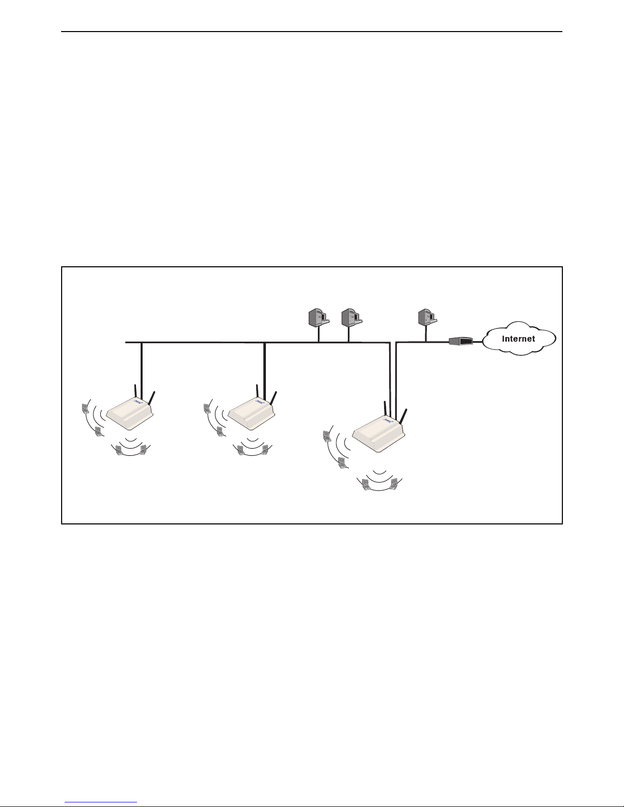
Scenario 2c: Hotspot with satellites and roaming
(via RADIUS server)
This scenario adds multiple APs to extend the wireless network in Scenario 2b.
AP devices can be used to extend the reach of the public access network created by a service
controller.
How it works
This scenario creates two virtual service communities (VSCs) on each AP. Each VSC provides
support for a different security option: 802.1X (with WEP) or WPA.
To connect with the wireless network, users must select the SSID of the VSC that matches the
option that they want to use. Roaming is supported, since the same VSCs are defined on all
access points.
Authentication of client stations is done by the service controller using accounts defined on a
RADIUS server.
Configuration road map
Note: Start with the configuration defined in Scenario 2b.
A. Install the APs
Install the APs as described in the appropriate Quickstart guide.
B. Switch the APs to autonomous mode
By default the APs are configured to operate in controlled mode. Switch them to autonomous mode
as follows:
1. Start the management tool and login.
2. On the home click Switch to Autonomous Mode. The AP will restart.
Page 31

HP MSM313/MSM323 Deployment Guide 29 2 Public/guest networks
3. Before you connect each unit to the LAN, start the management tool and configure each unit as
described in the sections that follow.
C. Configure the wireless network
By default the APs are configured to:
• support 802.11b/g clients
• automatically choose the best operating channel (frequency)
• create a wireless network named HP ProCurve
There is no need to change these settings for this scenario.
D. Set the shared secret on the service controller
1. Select Public access > Access control.
2. In the Access controller shared secret box, set Shared secret and Confirm shared secret
to a unique string. For example: xr2t56. This password will be used by the APs to send
authentication requests to the service controller.
3. Click Save.
E. Configure the connection to the service controller on the APs
Configure the following on each AP.
1. Select VSC > Profiles.
2. Click the HP ProCurve profile to edit it.
3. In the General box, select the Use HP ProCurve MSM controller check box.
4. Click Save.
5. Select Security > Access controller.
6. Set the Access controller shared secret to match the secret set on the service controller.
7. Click Save.
Note: By default the AP is set up to use the default gateway assigned by DHCP as the
access controller. Do not change this setting.
Page 32

HP MSM313/MSM323 Deployment Guide 30 2 Public/guest networks
LAN port
Internet port
192.168.1.0
1.2 1.3
Router
Firewall
RADIUS
server
LAN B
192.168.5.0
5.1
5.21.1
LAN A
Web
server
5.3
LAN
192.168.1.0
1.81.9
SSID
WPA
SSID
8021X
AP
SSID
WPA
SSID
8021X
Service
controller
Management
station
AP
SSID
WPA
SSID
8021X
Scenario 2d: Hotspot with layer 2 security (AAA
server)
This scenario adds support for 802.1X and WPA clients to scenario 2c.
This scenario shows how to enable wireless protection to safeguard transmissions against
eavesdropping.
How it works
This scenario creates two virtual service communities (VSCs) on each AP. Each VSC provides
support for a different security option: 802.1X (with WEP) or WPA.
To connect with the wireless network, users must select the SSID of the VSC that matches the
option that they want to use. Roaming is supported, since the same VSCs are defined on all
access points.
Authentication of client stations is done by the service controller using accounts defined on a
RADIUS server.
Configuration road map
Note: Start with the configuration defined in Scenario 2c.
A. Create VSCs on the APs
Follow this procedure to create three virtual service communities on all APs.
1. Select VSC > Profiles.
2. On the Virtual Service Communities page, click the HP ProCurve profile to edit it.
Page 33

HP MSM313/MSM323 Deployment Guide 31 2 Public/guest networks
3. On the Add/Edit Virtual Service Community page:
• Under General, set Name to None.
• Under General, select the Use HP ProCurve MSM controller check box.
• Under Virtual AP, set WLAN name (SSID) to None.
• Click Save.
4. On the Virtual Service Communities page, click Add new profile.
5. On the Add/Edit Virtual Service Community page:
• Under General, set Name to WPA.
• Under General, select the Use HP ProCurve MSM controller check box.
• Under Virtual AP, set WLAN name (SSID) to WPA.
• Under Wireless protection:
• Select the checkbox and leave the default setting of WPA.
• For Mode, select WPA (TKIP) or WPA2 (AES/CCMP).
• Leave Key source as RADIUS.
• Click Save.
6. On the Virtual Service Communities page, click Add new profile.
7. On the Add/Edit Virtual Service Community page:
• Under General, set Name to 8021X.
• Under General, select the Use HP ProCurve MSM controller check box.
• Under Virtual AP, set WLAN name (SSID) to 8021X.
• Under Wireless protection:
• Select the checkbox and select 802.1X.
• Select the Mandatory authentication checkbox.
• Select the WEP encryption checkbox.
• Click Save.
B. Create VSCs on the service controller
Follow this procedure to create virtual service communities on the service controller that match
each VSC you configured on the APs:
1. Select VSC > Profiles.
2. On the Virtual Service Communities page, click the HP ProCurve profile to edit it.
Page 34

HP MSM313/MSM323 Deployment Guide 32 2 Public/guest networks
3. On the Add/Edit Virtual Service Community page:
• Under General, set Name to None.
• Under Virtual AP, set WLAN name (SSID) to None.
• Under HTML-based user logins:
• Enable RADIUS authentication.
• For RADIUS profile, select RADIUS Profile 1 (which was defined in Scenario 2a).
• Click Save.
4. On the Virtual Service Communities page, click Add new profile.
5. On the Add/Edit Virtual Service Community page:
• Under General, set Name to WPA.
• Under Virtual AP, set WLAN name (SSID) to WPA.
• Under Wireless protection:
• Select the checkbox and leave the default setting of WPA.
• For Mode, select WPA (TKIP) or WPA2 (AES/CCMP).
• Leave Key source as RADIUS.
• For RADIUS profile, select RADIUS Profile 1 (which was defined in Scenario 2a).
• Clear the HTML-based user logins checkbox.
• Under Access controlled, clear the Redirect HTML users to login page checkbox.
• Click Save.
6. On the Virtual Service Communities page, click Add new profile.
7. On the Add/Edit Virtual Service Community page:
• Under General, set Name to 8021X.
• Under Virtual AP, set WLAN name (SSID) to 8021X.
• Under Wireless protection:
• Select the checkbox and select 802.1X.
• For RADIUS profile, select RADIUS Profile 1 (which was defined in Scenario 2a).
• Select the Mandatory authentication checkbox.
• Select the WEP encryption checkbox.
• Clear the HTML-based user logins checkbox.
• Under Access controlled, clear the Redirect HTML users to login page checkbox.
• Click Save.
Page 35

HP MSM313/MSM323 Deployment Guide 33 2 Public/guest networks
Scenario 2e: Using two radios to support A+B+G
traffic
This scenario adds support for 802.11a wireless clients to Scenario 2d.
HP multi-radio access points can be configured to support the same SSID on two different radios.
This enables a single device to support wireless clients regardless of the type of radio they have:
802.11a, b, or g.
How it works
In this scenario, the service controller used in conjunction with APs that have at least two radios
that support access point operation. The radios are configured to operate as follows:
• Radio 1: 802.11b/g mode
• Radio 2: 802.11a mode
The two wireless profiles created in Scenario 2d are changed to transmit and receive on both radio
1 and radio 2.
Users are now able to connect regardless of their radio type, and since 802.11a users are on a
separate radio they do not share bandwidth with users using 802.11 b/g.
Network topology
Note: See scenario 2d for a diagram of the network topology.
Configuration road map
Note: Start with the configuration defined in Scenario 2d.
A. Configure radio 2
1. Select Wireless > Radios.
2. Under Radio 2:
• Change Operating mode to Access point only.
• Change Wireless mode to 802.11a.
3. Click Save.
B. Configure VSC profiles
1. Select VSC > Profiles
2. Edit each VSC created in Scenario 2d (8021x, WPA, and none) as follows:
• Click the profile name.
• Under Virtual AP, set Transmit/receive on to Radio 1 and 2.
• Click Save.
Page 36
HP MSM313/MSM323 Deployment Guide 34 2 Public/guest networks
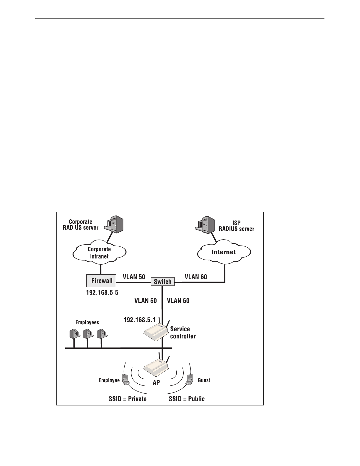
Scenario 3: Shared hotspot for public and private
traffic
In this scenario VLANs and multiple SSIDs are used to enable public and private users to share the
same infrastructure with complete security.
How it works
This scenario shows you how to deploy a wireless network so that it can be shared between
company employees and guests. It enables you to leverage a single wireless infrastructure to build
a hotspot and provide easy access for mobile employees.
• Employees connect using the SSID Private and are routed to the corporate network on VLAN
50. The service controller authenticates employees using the Corporate RADIUS server. Once
authenticated, employee traffic is forwarded on VLAN 50 so that it can reach the corporate
intranet. Employees use 802.1X to login. The service controller validates their login credentials
using the corporate RADIUS server.
•Users connect using the SSID Public and login using the service controller’s public access
interface. The service controller authenticates users using the ISP RADIUS server. Once
authenticated, user traffic is forwarded on VLAN 60 so that it can reach the Internet.
Page 37

HP MSM313/MSM323 Deployment Guide 35 2 Public/guest networks
Configuration road map
A. Define settings on the RADIUS servers
1. On the ISP RADIUS server create accounts for public users.
2. On the corporate RADIUS server create accounts for employees.
B. Install the service controller and AP
1. Install the service controller and AP as described in the appropriate quickstart guides.
2. Before you connect each unit to the LAN, start the Management Tool and configure each unit
as described in the sections that follow.
C. Switch the AP to autonomous mode
By default the AP is configured to operate in controlled mode. Switch it to autonomous mode as
follows:
1. Start the Management Tool and login.
2. On the home page click Switch to Autonomous Mode. The AP will restart.
Configure the service controller
A. Configure the Internet port
1. Select Network > Ports > Internet port.
2. Select No address (Support VLAN traffic only).
3. Click Save.
B. Create two RADIUS profiles
1. Select Security > RADIUS profiles.
2. Click Add New Profile.
• In the Profile name box, assign CorporateRADIUS to the new profile.
• In the Settings box, use the defaults except for Authentication method which must match
the method supported by the RADIUS server.
• In the Primary RADIUS server box, specify the address of the corporate RADIUS server
and the secret the service controller will use.
• Click Save.
3. Click Add New Profile.
• In the Profile name box, assign ISPRADIUS to the new profile.
• In the Settings box, use the defaults except for Authentication method which must match
the method supported by the RADIUS server.
• In the Primary RADIUS server box, specify the address of the ISP RADIUS server and the
secret the service controller will use.
• Click Save.
Page 38

HP MSM313/MSM323 Deployment Guide 36 2 Public/guest networks
C. Create VLANs
1. Select Network > Ports.
2. Under VLAN configuration, click Add New VLAN.
• Under General
• Leave the Port selection as Internet port.
• Set VLAN ID to 50.
• Set VLAN name to Private.
• Under Assign IP address via, select Static.
• Set IP address to 192.168.5.1.
• Set Mask to 255.255.255.0.
• Leave Gateway blank.
• Click Save.
3. Under VLAN configuration, click Add New VLAN.
• Under General
• Leave the Port selection as Internet port.
• Set VLAN ID to 60.
• Set VLAN name to Public.
• Under Assign IP address via, select DHCP client.
• Click Save.
D. Create VSCs
Use the following steps to create two virtual service communities on the service controller:
Note: This Private profile must be defined first to enable it to also support wired
employees, since untagged incoming traffic on the LAN port is always sent to the
first VSC profile.
1. Select VSC > Profiles.
2. On the Virtual Service Communities page, click the HP ProCurve profile to edit it.
3. On the Add/Edit Virtual Service Community page:
• Under General, set Name to Private.
• Under General, select the Provide access control checkbox.
• Under Virtual AP, set WLAN name (SSID) to Private.
• Under VSC ingress mapping, select SSID.
• Under VSC egress mapping, for Authenticated select Private.
Page 39

HP MSM313/MSM323 Deployment Guide 37 2 Public/guest networks
• Under Wireless protection:
• Select the checkbox and select 802.1X.
• Set RADIUS profile to CorporateRADIUS.
• Click Save.
4. On the Virtual Service Communities page, click Add new profile.
5. On the Add/Edit Virtual Service Community page:
• Under General, enter the Name as Public.
• Under Virtual AP, enter the WLAN name (SSID) as Public.
• Under VSC ingress mapping, select SSID.
• Under VSC egress mapping, for Authenticated select Public.
• Enable HTML-based user logins.
• Select the RADIUS authentication checkbox.
• For RADIUS Profile, select ISPRADIUS.
• Click Save.
E. Set the shared secret
1. Select Security > Authentication > Advanced Settings.
2. In the Access controller shared secret box, set Shared secret and Confirm shared secret
to a unique string. For example: xr2t56. This password will be used by the AP to send
authentication requests to the service controller.
3. Click Save.
Configure the AP
A. Create VSCs
1. Select VSC > Profiles.
2. On the Virtual Service Communities page, click the HP ProCurve profile to edit it.
3. On the Add/Edit Virtual Service Community page:
• Under General, enter the Name as Public.
• Under General, select the Use HP ProCurve MSM controller check box.
• Under Virtual AP, enter the WLAN name (SSID) as Public.
• Click Save.
4. On the Virtual Service Communities page, click Add new profile.
5. On the Add/Edit Virtual Service Community page:
• Under General, enter the Name as Private.
• Under General, select the Use HP ProCurve MSM controller check box.
Page 40

HP MSM313/MSM323 Deployment Guide 38 2 Public/guest networks
• Under Virtual AP, enter the WLAN name (SSID) as Private.
• Click Save.
B. Configure the connection to the service controller
1. Select Security > Access controller.
2. Set the Access controller shared secret to match the secret set on the service controller.
3. Click Save.
By default the AP is set up to use the same default gateway assigned by DHCP as the access
controller. Do not change this setting.
Page 41

HP MSM313/MSM323 Deployment Guide 39 2 Public/guest networks
Scenario 4: Delivering custom HTML pages using
VLANs
This scenario shows you how to split users onto different VLANs and take advantage of this to
deliver a customized user experience.
How it works
In this scenario a hotel assigns user traffic to a different VLAN based on an AP’s location within the
building.
• The APs serving the hotel rooms on each floor are configured to return user traffic on VLAN 40.
• The APs serving the hotel lobby, terrace, and restaurant are configured to return user traffic on
VLAN 50.
• VLAN 30 is defined for management purposes. It is used by the network administrator to reach
the management tool on the service controller and APs.
One advantage to this strategy is that it enables all devices to have the same SSID (Hotspot, for
example), making it easy for users to connect.
Custom content is triggered based on the VLAN ID to which user traffic is mapped.
Page 42

HP MSM313/MSM323 Deployment Guide 40 2 Public/guest networks
Note: In this scenario the service controller is used to provide access control functions only
and is not configured to support wireless clients.
Configuration road map
A. On the RADIUS server
Define accounts for all users and the service controller on the RADIUS server.
To deliver custom content based on the VLAN, add the following entry to the RADIUS profile for the
service controller.
welcome-url=web_server_URL/premium/welcome.html?VLAN=%v
Create a server-side script to retrieve the VLAN value and then display a custom Login page as
follows:
• If VLAN = 40, display the Login page for the hotel rooms.
• If VLAN = 50, display the Login page for the public areas.
B. Install the service controller and the APs
1. Install the devices as described in the appropriate Quickstart guide.
2. Before you connect each unit to the LAN, start the management tool and configure each unit as
described in the sections that follow.
C. Switch the APs to autonomous mode
By default the APs are configured to operate in controlled mode. Switch each one to autonomous
mode as follows:
1. Start the management tool and login.
2. On the home page click Switch to Autonomous Mode. The AP will restart.
D. Configure the wireless network
By default the service controller is configured to:
• support 802.11b/g clients
• automatically choose the best operating channel (frequency)
There is no need to change these settings for this scenario.
Note: By default, one radio on the multi-radio access point is used to provide the wireless
network and the other radio is placed into Monitor mode.
Configure the service controller
A. Configure the Internet port
1. Select Network > Ports > Internet port.
2. Select the addressing option as required by the LAN and click Configure.
3. Define all settings as required.
Page 43

HP MSM313/MSM323 Deployment Guide 41 2 Public/guest networks
B. Create a RADIUS profile
1. Select Security > RADIUS profiles.
2. Click Add New Profile.
• In the Profile name box, assign RADIUS1 to the new profile.
• In the Settings box, use the defaults except for Authentication method which must match
the method supported by the RADIUS server.
• In the Primary RADIUS server box, specify the address of the corporate RADIUS server
and the secret the service controller will use.
• Click Save.
C. Configure the service controller to retrieve attributes from the
RADIUS server
1. Select Public access > Attributes.
2. Select the Retrieve attributes using RADIUS option.
3. Select the RADIUS profile you defined (RADIUS Profile 1).
4. Specify the username and password the service controller will use to login to the RADIUS
server.
5. Click Retrieve Now. The service controller will login and retrieve the attributes.
6. Click Save.
D. Create VLANs
1. Select Network > Ports.
2. Under VLAN configuration, click Add New VLAN.
• Under General
• Leave the Port selection as LAN port.
• Set VLAN ID to 30.
• Set VLAN name to Management.
• Under Assign IP address via, select Static.
• Set IP address to 192.168.30.1.
• Set Mask to 255.255.255.0.
• Leave Gateway blank.
• Click Save.
Page 44

HP MSM313/MSM323 Deployment Guide 42 2 Public/guest networks
3. Under VLAN configuration, click Add New VLAN.
• Under General
• Leave the Port selection as LAN port.
• Set VLAN ID to 40.
• Set VLAN name to Guest.
• Under Assign IP address via, select None.
• Click Save.
4. Under VLAN configuration, click Add New VLAN.
• Under General
• Leave the Port selection as LAN port.
• Set VLAN ID to 50.
• Set VLAN name to Public.
• Under Assign IP address via, select None.
• Click Save.
E. Create VSCs
The following two virtual service communities need to be created on the service controller:
• Guest: Used for APs installed in hotel rooms. Forwards guest traffic on VLAN 40.
• Public: Used for APs installed in public spaces. Forwards public traffic on VLAN 50.
1. Select VSC > Profiles.
2. On the Virtual Service Communities page, click the HP ProCurve profile to edit it.
3. On the Add/Edit Virtual Service Community page:
• Under General, set Name to Guest.
• Under General, select the Provide access control checkbox.
• Under VSC ingress mapping, clear the SSID checkbox.
• Under VSC egress mapping, select VLAN then select Guest.
• Enable HTML-based user logins.
• Select the RADIUS authentication checkbox.
• For RADIUS Profile, select RADIUS1.
• Click Save.
4. On the Virtual Service Communities page, click Add new profile.
Page 45

HP MSM313/MSM323 Deployment Guide 43 2 Public/guest networks
5. On the Add/Edit Virtual Service Community page:
• Under General, set Name to Public.
• Under VSC ingress mapping, clear the SSID checkbox.
• Under VSC egress mapping, select VLAN and then select Public.
• Enable HTML-based user logins.
• Select the RADIUS authentication checkbox.
• For RADIUS Profile, select RADIUS1.
• Click Save.
F. Set the shared secret
1. Select Public access > Access control.
2. In the Access controller shared secret box, set Shared secret and Confirm shared secret
to a unique string. For example: xr2t56. This password will be used by the APs to send
authentication requests to the service controller.
3. Click Save.
Configure the APs
A. Set static addressing and management VLAN
1. Select Network > Ports.
2. Under Port configuration, click Bridge port.
• Under Assign IP address via, select Static then click the Configure button. Define the
following:
• For each AP, set IP address to a unique address on the 192.168.30.x subnet.
• Set Address mask to 255.255.255.0.
• Set Default gateway to 192.168.30.1.
• Click Save.
B. Configure management VLAN
1. Select Network > Ports.
2. Under Port configuration, click Port 1.
• Under VLAN
• Select the VLAN ID checkbox.
• Set VLAN ID to 30.
• Select the Restrict default VLAN to management traffic only checkbox.
• Click Save.
Page 46

HP MSM313/MSM323 Deployment Guide 44 2 Public/guest networks
C. Configure a VSC
1. Select VSC > Profiles.
2. On the Virtual Service Communities page, click the HP ProCurve profile.
3. On the Add/Edit Virtual Service Community page:
• Under General, set Name to Hotspot.
• Under General, select the Use HP ProCurve MSM controller check box.
• Under Virtual AP, set WLAN name (SSID) to Hotspot.
• Under Egress VLAN:
• If the AP is serving a hotel room, set VLAN ID to 40 (which corresponds to the Guest
VLAN).
• If the AP is serving a public area, set VLAN ID to 50 (which corresponds to the Public
VLAN).
• Click Save.
D. Configure the connection to the service controller
1. Select Security > Access controller.
2. Set the Access controller shared secret to match the secret set on the service controller.
3. Click Save.
Page 47

HP MSM313/MSM323 Deployment Guide 45 2 Public/guest networks
Scenario 5: Custom HTML pages on each AP
This scenario describes how to create a customized user experience based on the AP with which a
user is associated. This scenario uses locally configured attributes and does not require a RADIUS
server.
How it works
In this scenario wireless networking for a condo complex is deployed using multiple APs and a
single service controller. The complex features three buildings, each with several condos serviced
by a single AP.
Since tenant turnover is low, and network access is included in the monthly condo fee, accounting
support is not needed. Therefore this scenario does not use a RADIUS server. Instead, all logins
are validated by the service controller using a locally defined user list.
To offer personalized service for each building, a set of custom web pages are created for each
building and stored in a separate folder on a web server. (A third-party server on the Internet is
used to keep costs down.) Users are redirected to the appropriate set of pages based on the
location-aware group name assigned to each AP.
About the location-aware feature
This feature, which is enabled by default, permits the service controller to determine the physical
location where users are logging into the network (as well as other information which can used for
user tracking). See the HP MSM313/MSM323 Network Access Configuration Guide for more
information on this feature.
This scenario uses the location-aware group name feature to assign a unique name to each AP.
When a user logs in, the AP reports this name to the service controller. The name is then used to
create a URL to a custom set of pages on the web server.
Page 48

HP MSM313/MSM323 Deployment Guide 46 2 Public/guest networks
Configuration road map
A. Install the service controller and the APs
1. Install the devices as described in the appropriate Quickstart guide.
2. Before you connect each unit to the LAN, start the management tool and configure each unit as
described in the sections that follow.
B. Switch the APs to autonomous mode
By default the APs are configured to operate in controlled mode. Switch each one to autonomous
mode as follows:
1. Start the management tool and login.
2. On the home page click Switch to Autonomous Mode. The AP will restart.
C. Create the custom web pages on the web server
Before you can customize the pages, you must retrieve the Examples zip file and extract the
contents to a folder on your computer. (See “Examples” on page 15. for instructions on how to
retrieve it.)
1. Create the following folder on the web server: \newpages
2. Create a file called logo.gif that contains a custom logo for the service being offered and place
it in \newpages.
3. Copy the following files from the MSM Public Access Examples zip file and place them in the
newpages folder.
• welcome.html
• goodbye.html
• fail.html
4. Create the following three folders on the web server:
\newpages\complex_1
\newpages\complex_2
\newpages\complex_3
5. Create the following three html files in each of the three new folders. Customize each file so
that it provide content specific to each condo complex:
login.html
This is the page tenants will use to log in. The following sample code illustrates how to retrieve
login credentials and send them to the service controller for validation.
<form action=https://wireless.colubris.com:8090/goform/HtmlLoginRequest>
<input type=”text” name=”username” id=”username” />
<input type=”text” name=”password” id=”password” />
<input type=”submit” />
</form>
welcome.html
This is the page tenants will see after their login is approved. It is a standard HTML page and
can be customized as required.
Page 49

HP MSM313/MSM323 Deployment Guide 47 2 Public/guest networks
goodbye.html
This is the page tenants will see after they logout. It is a standard HTML page and can be
customized as required.
Configure the APs
A. Configure the wireless network
By default each AP is configured to:
• Automatically select the best operating frequency.
• Create a wireless network named HP ProCurve.
• Act as a DHCP client on its LAN ports.
• Use the service controller as the access controller.
There is no need to change these settings for this scenario.
B. Configure the location-aware group name
Set a unique group name on each AP as follows:
1. Select VSC > Profiles.
2. Click the HP ProCurve profile to edit it.
3. Under General, make sure that the Use HP ProCurve MSM controller checkbox is selected.
4. Under Location aware:
• For AP 1, set Group name to Complex_1.
• For AP 2, set Group name to Complex_2.
• For AP 3, set Group name to Complex_3.
5. Click Save.
C. Configure the connection to the service controller on the APs
Each AP will use the services of the service controller to authenticate user logins. Do the following
on each AP.
1. Select Security > Access controller
2. Set the Access controller shared secret to the same unique value on all APs. For example:
xr2t56. This password will be used by the APs to connect to the service controller when they
send authentication requests.
3. Click Save.
Note: By default the AP is set up to use the default gateway assigned by DHCP as the
access controller. Do not change this setting.
Page 50

HP MSM313/MSM323 Deployment Guide 48 2 Public/guest networks
Configure the service controller
A. Configure the Internet port
1. Select Network > Ports > Internet port.
2. Select the addressing option required by your ISP.
3. Click Configure and define all settings as required.
B. Configure attributes to activate the customized pages
1. Open the Public access > attributes page and add the following attributes to the Configured
attributes table:
The first four attributes provide support for the common pages that are generic for all tenants,
and the shared logo file.
transport-page=web_server_URL/newpages/transport.html
session-page=web_server_URL/newpages/session.html
fail-page=web_server_URL/newpages/fail.html
logo=web_server_URL/newpages/logo.gif
The next three attributes provide support for the custom pages. Each time a tenant logs in the
service controller calls these pages, replacing the %G with the group name assigned to the AP
that the tenant is associated with.
login-url=web_server_URL/newpages/%G/login.html
welcome-url=web_server_URL/newpages/%G/welcome.html
goodbye-url=web_server_URL/newpages/%G/goodbye.html
By default the service controller blocks access to any resources that are connected to its
Internet port until a client station successfully logs in. However, to log in, a client station must
be able to load the custom login page hosted on the web server. To solve this problem, an
access list definition is added that permits access to the web server for all unauthenticated
stations.
Access-list=loginpage,ACCEPT,tcp,web_server_URL,80
Use-access-list=loginpage
C. Define the list of condo tenants
1. Select Public access > Users.
2. Add usernames and passwords for all condo tenants.
D. Set the shared secret on the service controller
1. Select Public access > Access control.
2. In the Access controller shared secret box, set Shared secret and Confirm shared secret
to the same value you set on the APs.
3. Click Save.
Page 51

HP MSM313/MSM323 Deployment Guide 49 2 Public/guest networks
E. Setup location aware
1. Select VSC > Profiles.
2. Click the HP ProCurve profile to edit it.
3. Under Location aware, set Called-Station-Id content to group.
4. Click Save.
F. Using the public access interface
To use the condo internet service, tenants do the following:
• Connect to the SSID HP ProCurve using 80211.b or g.
• Start their web browser and specify the URL wireless.colubris.com which is the URL assigned
to the service controller.
• The service controller will redirect the browser to the login page on the web server.
• After the tenant logs in and is validated, the Welcome page is displayed.
• The tenant can now surf the Internet.
Page 52

HP MSM313/MSM323 Deployment Guide 50 2 Public/guest networks
Scenario 6: Multi-site installation (distributed
architecture)
This scenario shows you how to create a multi-site installation using multiple service controllers.
How it works
In this scenario, multiple series 3x3 service controllers are installed to offer public access
networking at a number of different physical locations.
Each service controller is connected to the Internet using a broadband modem. The Internet
connection is protected by the service controller’s firewall and NAT features.
A NOC (network operations center) is located at a remote site and provides a RADIUS server for
authentication, and a web server to store custom public access interface pages.
Page 53

HP MSM313/MSM323 Deployment Guide 51 2 Public/guest networks
Configuration road map
A. On the RADIUS server
Define RADIUS accounts for all users that will use the public access network.
B. Install the service controllers
1. Install the service controllers at each site as described in the appropriate Quickstart guide.
2. Connect the Internet port on each unit to a broadband modem that is connected to the Internet.
3. Start the management tool and configure each unit as described in the sections that follow.
C. Configure the Internet port
1. Select Network > Ports > Internet port.
2. Select the addressing option as required by your ISP and click Configure.
3. Define all settings as required.
D. Configure the wireless network
By default the service controller is configured to:
• support 802.11b/g clients
• automatically choose the best operating channel (frequency)
• create a wireless network named HP ProCurve
There is no need to change these settings for this scenario.
E. Create a RADIUS profile
1. Select Security > RADIUS profiles.
2. Click Add New Profile.
• In the Profile name box, assign RADIUS1 to the new profile.
• In the Settings box, use the defaults except for Authentication method which must match
the method supported by the RADIUS server.
• In the Primary RADIUS server box, specify the address of the RADIUS server at the NOC
and the secret the service controller will use.
• Click Save.
F. Configure the VSC
1. Select VSC > Profiles.
2. On the Virtual Service Communities page, click the HP ProCurve profile.
Page 54

HP MSM313/MSM323 Deployment Guide 52 2 Public/guest networks
3. On the Add/Edit Virtual Service Community page:
• Under HTML-based user logins:
• Clear the Local authentication checkbox.
• Select the RADIUS authentication checkbox.
• For RADIUS profile, select RADIUS1.
• Select the RADIUS accounting checkbox.
• Click Save.
G. Customize the login page and logo
Before you can customize the pages, you must retrieve the Examples zip file and extract the
contents to a folder on your computer. (See “Examples” on page 15. for instructions on how to
retrieve it.)
1. Create a folder called newpages on the web sever.
2. Create a file called logo.gif that contains your logo and place it in the newpages folder
(recommended size less than 20K). This same image file is shared by all pages.
3. Copy the following files from the MSM Public Access Examples zip file and place them in the
newpages folder.
• login.html
• transport.html
• session.html
• fail.html
4. Edit login.html to meet the requirements of your site, keeping the following restrictions in
mind:
• Do not alter the ID tags “<!-- Colubris -->” & “<!-- Custom -->” located at the top of the page.
• Do not alter any JavaScript code.
H. Define attributes on the RADIUS server
On the RADIUS server, define an account for the service controller and add the following entries to
it.
login-page=web_server_URL/newpages/login.html
transport-page=web_server_URL/newpages/transport.html
session-page=web_server_URL/newpages/session.html
fail-page=web_server_URL/newpages/fail.html
logo=web_server_URL/newpages/logo.gif
For more information on these attributes, consult the HP MSM313/MSM323 Network Access
Configuration Guide.
Page 55

HP MSM313/MSM323 Deployment Guide 53 2 Public/guest networks
I. Configure the service controller to retrieve attributes from the
RADIUS server
The service controller will retrieve the configuration attributes defined on the RADIUS server each
time it authenticates with the server.
1. Select Public access > Attributes.
2. Select the Retrieve attributes using RADIUS option.
3. Select the RADIUS profile you defined earlier (RADIUS1).
4. Specify the username and password the service controller will use to login to the RADIUS
server.
5. Click Retrieve Now. The service controller will login and retrieve the attributes.
6. Click Save.
J. Using the public access interface
To use the internet service, users do the following:
• Connect to the SSID HP ProCurve using 80211.b or g.
• Start their web browser and specify the URL wireless.colubris.com which is the URL assigned
to the service controller.
• The service controller will redirect the browser to the custom login page on the web server.
• After the user logs in and is validated, the Welcome page is displayed.
• The user can now surf the Internet.
Page 56

HP MSM313/MSM323 Deployment Guide 54 2 Public/guest networks
Scenario 7: Multi-site installation (centralized
architecture)
This scenario shows you how to create a multi-site installation using multiple service controllers to
tunnel traffic back to a central location.
How it works
In this scenario, multiple series 3x3 service controllers are installed to offer public access
networking at a number of different physical locations. The service controllers provide wireless
network services at each site, but do not authenticate users. Instead all user traffic is forwarded to
the third-party access controller at the NOC via secure GRE tunnels.
Configuration road map
A. Install the service controllers
1. Install the service controllers at each site as described in the appropriate Quickstart guide.
2. Connect the Internet port on each unit to a broadband modem that is connected to the Internet.
3. Start the management tool and configure each unit as described in the sections that follow.
Page 57

HP MSM313/MSM323 Deployment Guide 55 2 Public/guest networks
B. Configure the Internet port
1. Select Network > Ports > Internet port.
2. Select the addressing option as required by your ISP and click Configure.
3. Define all settings as required.
C. Configure the wireless network
By default the service controller is configured to:
• support 802.11b/g clients
• automatically choose the best operating channel (frequency)
• create a wireless network named HP ProCurve
There is no need to change these settings for this scenario.
D. Configure the GRE tunnels
1. Select Network > Ports.
2. Under GRE tunnel configuration, click Add new GRE tunnel.
3. Under Tunnel settings,
• For Name, specify a name for this profile. For example: GRE_Tunnel.
• For Local tunnel IP address, specify the IP address of the service controller inside the
tunnel.
• For Remote tunnel IP address, specify the IP address (inside the tunnel) of the GRE
terminator in the NOC.
• For Tunnel IP mask, specify the mask associated with the IP addresses inside the tunnel.
• For GRE peer IP address, specify the IP address of the GRE terminator in the NOC.
4. Click Save.
E. Configure the VSC
1. Select VSC > Profiles.
2. On the Virtual Service Communities page, click the HP ProCurve profile.
3. On the Add/Edit Virtual Service Community page:
• Under General, select the Provide access control checkbox.
• Under VSC egress mapping, select GRE_Tunnel for Unauthenticated,
Authenticated, and Intercepted.
• Under HTML-based user logins, clear the Local authentication checkbox.
• Click Save.
Page 58

HP MSM313/MSM323 Deployment Guide 56 2 Public/guest networks
Page 59

Chapter 3: Local mesh deployment
Local mesh deployment
Contents
Scenario 1a: Dynamic local mesh - - - - - - - - - - - - - - - - - - - - - 58
Scenario 1b: Dynamic local mesh with load balancing - - - - - - - - - - - 65
3
Scenario 2: Creating a self-healing network - - - - - - - - - - - - - - - - 67
Page 60

HP MSM313/MSM323 Deployment Guide 58 3 Local mesh deployment
Scenario 1a: Dynamic local mesh
This scenario makes use of a service controller, several autonomous APs, and dynamic
local mesh links.
The HP local mesh implementation features dynamic links which can be used to automatically
configure setups.
Note: In this chapter, the MSM313 and MSM323 Integrated Services Access Points are
referred to as "service controllers" and MSM Access Points are referred to as "APs."
How it works
In this scenario, an MSM323 is used in conjunction with several dual-radio APs to provide wireless
networking to a large exhibition hall. To eliminate setup time, and to increase the flexibility of
wireless coverage, dynamic wireless bridges are used to link the APs to the backbone network.
The APs are configured as local mesh slave nodes, all with the same local mesh ID. This ensures
that they all connect to the master, resulting in a single wireless hop for all network traffic.
Page 61

HP MSM313/MSM323 Deployment Guide 59 3 Local mesh deployment
Three virtual service communities (VSCs) are defined on each device. Each VSC provides support
for a different security option: WEP, WPA (with preshared key), and none. To connect with the
wireless network, users must select the SSID of the VSC that matches the option that they want to
use and then login using the public access interface created by the service controller. Roaming is
supported, since the same VSCs are defined on all APs.
For optimum performance, the APs and the service controller use 802.11b/g mode to support
wireless clients and 802.11a mode to create the local mesh links.
Configuration road map
A. Install the APs and the service controller
Install the APs and the service controller as described in their quickstart guides.
B. Switch the APs to autonomous mode
By default the APs are configured to operate in controlled mode. Switch them to autonomous mode
as follows:
1. Start the management tool and login.
2. On the home click Switch to Autonomous Mode. The AP will restart.
3. Before you connect each unit to the LAN, start the management tool and configure each unit as
described in the sections that follow.
AP configuration
A. Configure addressing
By default APs operate as a DHCP client. In the sample topology they are automatically assigned
IP addresses by the DHCP server on the service controller.
To make the APs easier to manage however, it may be useful to assign a static IP address to them
as follows:
1. Select Network > Ports.
2. Under Port configuration, click Bridge port.
3. Under Assign IP address via, select Static then click the Configure button.
4. Set the static addressing parameters as required by the network and click Save.
5. Set IP address to 192.168.10.x. Replace x with a different number for each AP.
6. Set Address mask to 255.255.255.0.
7. Set Default gateway to 192.168.10.1 (which is the address of the service controller).
Page 62

HP MSM313/MSM323 Deployment Guide 60 3 Local mesh deployment
B. Configure the radios
For optimum performance, the wireless channel used for the wireless bridge should be different
and non-overlapping with the channel used to support wireless client stations.
One effective way to meet this challenge is to use 802.11b/g mode to support wireless clients and
802.11a mode to create the bridge.
Configure all APs as follows:
1. Select Wireless > Radios.
2. Under Radio 1:
• Set Operating mode to Access point only.
• Set Wireless mode to 802.11b + 802.11g.
• Set Channel to Automatic.
3. Under Radio 2:
• Set Operating mode to Local mesh only.
• Set Wireless mode to 802.11a.
• Set Channel to Automatic.
4. Click Save.
C. Configure the local mesh links
Configure all APs as follows:
1. Select Wireless > Local mesh.
2. Click Add New Profile.
3. Set Name to Local mesh #1.
4. Under Settings:
• Select Enabled.
• For Use, select Radio 2.
5. Under Security:
• Enable the checkbox.
• Select AES/CCMP.
• For PSK, specify between 8 and 64 ASCII characters. It is recommended that the key be at
least 20 characters long and be a mix of letters and numbers.
6. Under Addressing,
• Select Dynamic.
• For Mode, select Slave.
• Leave Mesh ID set to the default value of 1.
7. Click Save.
Page 63

HP MSM313/MSM323 Deployment Guide 61 3 Local mesh deployment
D. Configure the connection to the service controller on the APs
Configure the following on each AP.
1. Select VSC > Profiles.
2. Click the HP ProCurve profile to edit it.
3. In the General box, select the Use HP ProCurve MSM controller check box.
4. Click Save.
5. Select Security > Access controller.
6. Set the Access controller shared secret to match the secret set on the service controller.
7. Click Save.
Note: By default the AP is set up to use the default gateway assigned by DHCP as the
access controller. Do not change this setting.
E. Create VSCs on the APs
Follow this procedure to create three virtual service communities on all APs.
1. Select VSC > Profiles.
2. On the Virtual Service Communities page, click the HP ProCurve profile to edit it.
3. On the Add/Edit Virtual Service Community page:
• Under General, set Name to None.
• Under General, select the Use HP ProCurve MSM controller check box.
• Under Virtual AP, set WLAN name (SSID) to None.
• Click Save.
4. On the Virtual Service Communities page, click Add new profile.
5. On the Add/Edit Virtual Service Community page:
• Under General, set Name to WPA.
• Under General, select the Use HP ProCurve MSM controller check box.
• Under Virtual AP, set WLAN name (SSID) to WPA.
• Under Wireless protection:
• Select the checkbox and leave the default setting of WPA.
• For Mode, select WPA (TKIP) or WPA2 (AES/CCMP).
• Leave Key source as RADIUS.
• Click Save.
6. On the Virtual Service Communities page, click Add new profile.
7. On the Add/Edit Virtual Service Community page:
• Under General, set
• Under General, select the Use HP ProCurve MSM controller check box.
Name to 8021X.
Page 64

HP MSM313/MSM323 Deployment Guide 62 3 Local mesh deployment
• Under Virtual AP, set WLAN name (SSID) to 8021X.
• Under Wireless protection:
• Select the checkbox and select 802.1X.
• Select the Mandatory authentication checkbox.
• Select the WEP encryption checkbox.
• Click Save.
Service controller configuration
A. Configure the Internet port
1. Select Network > Ports > Internet port.
2. Select Static and click Configure.
3. Under Settings:
• Set IP address to 192.168.5.3.
• Set Address mask to 255.255.255.0.
• Click Save.
B. Set the shared secret on the service controller
1. Select Public access > Access control.
2. In the Access controller shared secret box, set Shared secret and Confirm shared secret
to a unique string. For example: xr2t56. This password will be used by the APs to send
authentication requests to the service controller.
3. Click Save.
C. Create a RADIUS profile
1. Select Security > RADIUS profiles.
2. Click Add New Profile.
3. In the Profile name box, assign RADIUS Profile 1 to the new profile.
4. In the Settings box, use the defaults except for Authentication method which must match the
method supported by the RADIUS server.
5. In the Primary RADIUS server box, specify the address of the RADIUS server and the secret
the service controller will use to login.
D. Create VSCs on the service controller
Follow this procedure to create virtual service communities on the service controller that match
each VSC you configured on the APs:
1. Select VSC > Profiles.
2. On the Virtual Service Communities page, click the HP ProCurve profile to edit it.
Page 65

HP MSM313/MSM323 Deployment Guide 63 3 Local mesh deployment
3. On the Add/Edit Virtual Service Community page:
• Under General, set Name to None.
• Under Virtual AP, set WLAN name (SSID) to None.
• Under HTML-based user logins:
• Enable RADIUS authentication.
• For RADIUS profile, select RADIUS Profile 1.
• Click Save.
4. On the Virtual Service Communities page, click Add new profile.
5. On the Add/Edit Virtual Service Community page:
• Under General, set Name to WPA.
• Under Virtual AP, set WLAN name (SSID) to WPA.
• Under Wireless protection:
• Select the checkbox and leave the default setting of WPA.
• For Mode, select WPA (TKIP) or WPA2 (AES/CCMP).
• Leave Key source as RADIUS.
• For RADIUS profile, select RADIUS Profile 1.
• Clear the HTML-based user logins checkbox.
• Under Access controlled, clear the Redirect HTML users to login page checkbox.
• Click Save.
6. On the Virtual Service Communities page, click Add new profile.
7. On the Add/Edit Virtual Service Community page:
• Under General, set Name to 8021X.
• Under Virtual AP, set WLAN name (SSID) to 8021X.
• Under Wireless protection:
• Select the checkbox and select 802.1X.
• For RADIUS profile, select RADIUS Profile 1.
• Select the Mandatory authentication checkbox.
• Select the WEP encryption checkbox.
• Clear the HTML-based user logins checkbox.
• Under Access controlled, clear the Redirect HTML users to login page checkbox.
• Click Save.
Page 66

HP MSM313/MSM323 Deployment Guide 64 3 Local mesh deployment
E. Configure the radios
1. Select Wireless > Radios.
2. Under Radio 1:
• Set Operating mode to Local mesh only.
• Set Wireless mode to 802.11a.
• Set Channel to Automatic.
3. Clear the Radio 2 checkbox.
4. Click Save.
F. Configure the local mesh link
1. Select Wireless > Local mesh.
2. Click Add New Profile.
3. Set Name to Local mesh #1.
4. Under Settings:
• Select Enabled.
• For Use, select Radio 1.
5. Under Security:
• Enable the checkbox.
• Select AES/CCMP.
• For PSK, specify between 8 and 64 ASCII characters. It is recommended that the key be at
least 20 characters long and be a mix of letters and numbers.
6. Under Addressing,
• Select Dynamic.
• For Mode, select Master.
7. Click Save.
Page 67
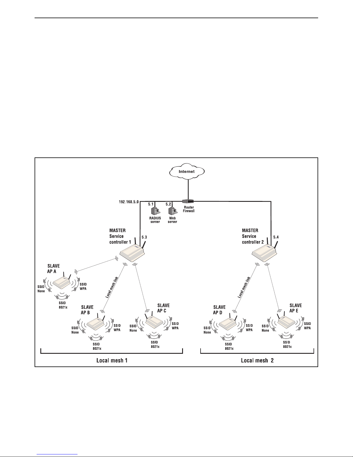
HP MSM313/MSM323 Deployment Guide 65 3 Local mesh deployment
Scenario 1b: Dynamic local mesh with load
balancing
This scenario adds an additional service controller and autonomous APs to extend the
network in Scenario 1a.
This scenario illustrates how to use local mesh links to split traffic.
How it works
In this scenario, service controller 2 is added to the network defined in Scenario 1a to support
traffic from additional slaves. Service controller 2 is also configured as a master node, but with a
different local mesh ID from service controller 1. As additional slaves are added to the network,
traffic can be balanced by setting their local mesh ID to either 1 or 2.
Note: The SSIDs created on service controller 1 and service controller 2 are the same as
in scenario 1a and are not shown in this diagram.
Page 68

HP MSM313/MSM323 Deployment Guide 66 3 Local mesh deployment
Configuration road map
Note: Start with the configuration defined in Scenario 1a.
A. Install and configure the AP D and AP E
Install and configure AP D and AP E with the same settings used for the APs in scenario 1a with
the following difference: when configuring the local mesh links, change the Mesh ID from its default
setting of 1 to 2.
B. Install and configure service controller 2
Install and configure the service controller 2 with the same settings used for service controller 1 in
scenario 1a, with the following difference: when configuring the local mesh links, change the Mesh
ID from its default setting of 1 to 2.
Page 69

HP MSM313/MSM323 Deployment Guide 67 3 Local mesh deployment
Router
Firewall
RADIUS
server
192.168.5.0
5.1
5.2
Web
server
5.3
ALTERNATE
MASTER
AP 1
MASTER
Service
controller
ALTERNATE
MASTER
AP 3
ALTERNATE
MASTER
AP 2
ALTERNATE
MASTER
AP 4
ALTERNATE
MASTER
AP 5
ALTERNATE
MASTER
AP 2
When AP 2 is unavailable, the network dynamically reconfigures itselfInitial network configuration is automatically established
Router
Firewall
RADIUS
server
192.168.5.0
5.1
5.2
Web
server
5.3
ALTERNATE
MASTER
AP 1
ALTERNATE
MASTER
AP 3
ALTERNATE
MASTER
AP 4
ALTERNATE
MASTER
AP 5
MASTER
Service
controller
Scenario 2: Creating a self-healing network
This scenario makes use of a service controller, several autonomous APs, and dynamic
local mesh links.
This scenario illustrates how to use local mesh links to deploy a wireless infrastructure that can
automatically adjust to network changes.
How it works
In this scenario, an service controller is deployed with several dual-radio APs (operating in
autonomous mode) to provide wireless coverage. The service controller is configured as the
master node and the APs are all configured as alternate master nodes.
The links between the nodes are automatically established, based on a balance between SNR
(signal to noise ratio) and hops, to provide the most efficient network topology.
If a node becomes unavailable, the links automatically adjust to find the optimum path to the
master.
Page 70

HP MSM313/MSM323 Deployment Guide 68 3 Local mesh deployment
For optimum performance, the APs use 802.11b/g mode on radio 1 to support wireless clients and
802.11a mode on radio 2 to create the links.
Configuration road map
A. Install the APs
Install the AP as described in the Quickstart guide.
B. Switch the APs to autonomous mode
By default the APs are configured to operate in controlled mode. Switch them to autonomous mode
as follows:
1. Start the management tool and login.
2. On the home click Switch to Autonomous Mode. The AP will restart.
3. Before you connect each unit to the LAN, start the management tool and configure each unit as
described in the sections that follow.
AP configuration
A. Configure addressing
By default APs operate as a DHCP client. In the sample topology they are automatically assigned
IP addresses by the DHCP server on the service controller.
To make the APs easier to manage however, it may be useful to assign a static IP address to them
as follows:
1. Select Network > Ports.
2. Under Port configuration, click Bridge port.
3. Under Assign IP address via, select Static then click the Configure button.
4. Set the static addressing parameters as required by the network and click Save.
5. Set IP address to 192.168.10.x. Replace x with a different number for each AP.
6. Set Address mask to 255.255.255.0.
7. Set Default gateway to 192.168.10.1 (which is the address of the service controller).
Page 71

HP MSM313/MSM323 Deployment Guide 69 3 Local mesh deployment
B. Configure the radios
Configure all APs as follows:
1. Select Wireless > Radios.
2. Under Radio 1:
• Set Operating mode to Access point only.
• Set Wireless mode to 802.11b + 802.11g.
• Set Channel to Automatic.
3. Under Radio 2:
• Set Operating mode to Local mesh only.
• Set Wireless mode to 802.11a.
• Set Channel to Automatic.
4. Click Save.
C. Configure the local mesh links
Configure all APs as follows:
1. Select Wireless > Local mesh.
2. Click Add New Profile.
3. Set Name to Local mesh #1.
4. Under Settings:
• Select Enabled.
• For Use, select Radio 2.
5. Under Security:
• Enable the checkbox.
• Select AES/CCMP.
• For PSK, specify between 8 and 63 ASCII characters. It is recommended that the key be at
least 20 characters long and be a mix of letters and numbers.
6. Under Addressing,
• Select Dynamic.
• For Mode, select Alternate Master.
• For Mesh ID, leave the default setting of 1.
7. Click Save.
D. Configure the connection to the service controller on the APs
Configure the following on each AP.
1. Select VSC > Profiles.
2. Click the HP ProCurve profile to edit it.
Page 72

HP MSM313/MSM323 Deployment Guide 70 3 Local mesh deployment
3. In the General box, select the Use HP ProCurve MSM controller check box.
4. Click Save.
5. Select Security > Access controller.
6. Set the Access controller shared secret to match the secret set on the service controller.
7. Click Save.
Note: By default the AP is set up to use the default gateway assigned by DHCP as the
access controller. Do not change this setting.
E. Create VSCs on the APs
Follow this procedure to create three virtual service communities on all APs.
1. Select VSC > Profiles.
2. On the Virtual Service Communities page, click the HP ProCurve profile to edit it.
3. On the Add/Edit Virtual Service Community page:
• Under General, set Name to None.
• Under General, select the Use HP ProCurve MSM controller check box.
• Under Virtual AP, set WLAN name (SSID) to None.
• Click Save.
4. On the Virtual Service Communities page, click Add new profile.
5. On the Add/Edit Virtual Service Community page:
• Under General, set Name to WPA.
• Under General, select the Use HP ProCurve MSM controller check box.
• Under Virtual AP, set WLAN name (SSID) to WPA.
• Under Wireless protection:
• Select the checkbox and leave the default setting of WPA.
• For Mode, select WPA (TKIP) or WPA2 (AES/CCMP).
• Leave Key source as RADIUS.
• Click Save.
6. On the Virtual Service Communities page, click Add new profile.
7. On the Add/Edit Virtual Service Community page:
• Under General, set Name to 8021X.
• Under General, select the Use HP ProCurve MSM controller check box.
• Under Virtual AP, set WLAN name (SSID) to 8021X.
Page 73

HP MSM313/MSM323 Deployment Guide 71 3 Local mesh deployment
• Under Wireless protection:
• Select the checkbox and select 802.1X.
• Select the Mandatory authentication checkbox.
• Select the WEP encryption checkbox.
• Click Save.
Service controller configuration
A. Configure the Internet port
1. Select Network > Ports > Internet port.
2. Select Static and click Configure.
3. Under Settings:
• Set IP address to 192.168.5.3.
• Set Address mask to 255.255.255.0.
• Click Save.
B. Set the shared secret on the service controller
1. Select Public access > Access control.
2. In the Access controller shared secret box, set Shared secret and Confirm shared secret
to a unique string. For example: xr2t56. This password will be used by the APs to send
authentication requests to the service controller.
3. Click Save.
C. Create a RADIUS profile
1. Select Security > RADIUS profiles.
2. Click Add New Profile.
3. In the Profile name box, assign RADIUS Profile 1 to the new profile.
4. In the Settings box, use the defaults except for Authentication method which must match the
method supported by the RADIUS server.
5. In the Primary RADIUS server box, specify the address of the RADIUS server and the secret
the service controller will use to login.
D. Create VSCs on the service controller
Follow this procedure to create virtual service communities on the service controller that match
each VSC you configured on the APs:
1. Select VSC > Profiles.
2. On the Virtual Service Communities page, click the HP ProCurve profile to edit it.
Page 74

HP MSM313/MSM323 Deployment Guide 72 3 Local mesh deployment
3. On the Add/Edit Virtual Service Community page:
• Under General, set Name to None.
• Under Virtual AP, set WLAN name (SSID) to None.
• Under HTML-based user logins:
• Enable RADIUS authentication.
• For RADIUS profile, select RADIUS Profile 1.
• Click Save.
4. On the Virtual Service Communities page, click Add new profile.
5. On the Add/Edit Virtual Service Community page:
• Under General, set Name to WPA.
• Under Virtual AP, set WLAN name (SSID) to WPA.
• Under Wireless protection:
• Select the checkbox and leave the default setting of WPA.
• For Mode, select WPA (TKIP) or WPA2 (AES/CCMP).
• Leave Key source as RADIUS.
• For RADIUS profile, select RADIUS Profile 1.
• Clear the HTML-based user logins checkbox.
• Under Access controlled, clear the Redirect HTML users to login page checkbox.
• Click Save.
6. On the Virtual Service Communities page, click Add new profile.
7. On the Add/Edit Virtual Service Community page:
• Under General, set Name to 8021X.
• Under Virtual AP, set WLAN name (SSID) to 8021X.
• Under Wireless protection:
• Select the checkbox and select 802.1X.
• For RADIUS profile, select RADIUS Profile 1.
• Select the Mandatory authentication checkbox.
• Select the WEP encryption checkbox.
• Clear the HTML-based user logins checkbox.
• Under Access controlled, clear the Redirect HTML users to login page checkbox.
• Click Save.
Page 75

HP MSM313/MSM323 Deployment Guide 73 3 Local mesh deployment
E. Configure the radios
1. Select Wireless > Radios.
2. Under Radio 1:
• Set Operating mode to Access point only.
• Set Wireless mode to 802.11a.
• Set Channel to Automatic.
3. Clear the Radio 2 checkbox.
4. Click Save.
F. Configure the local mesh link
1. Select Wireless > Local mesh.
2. Click Add New Profile.
3. Set Name to Local mesh #1.
4. Under Settings:
• Select Enabled.
• For Use, select Radio 1.
5. Under Security:
• Enable the checkbox.
• Select AES/CCMP.
• For PSK, specify between 8 and 64 ASCII characters. It is recommended that the key be at
least 20 characters long and be a mix of letters and numbers.
6. Under Addressing,
• Select Dynamic.
• For Mode, select Master.
• For Mesh ID, leave the default setting of 1.
7. Click Save.
Page 76

HP MSM313/MSM323 Deployment Guide 74 3 Local mesh deployment
Page 77

Page 78

ProCurve 5400zl Switches
Deployment Guide
July 2010
Manual Part Number
5998-0453
Technology for better business outcomes
To learn more, visit www.hp.com/networking/
© Copyright 2010 Hewlett-Packard Development Company, L.P. The information
contained herein is subject to change without notice. The only warranties for HP products
and services are set forth in the express warranty statements accompanying such products
and services. Nothing herein should be construed as constituting an additional warranty.
HP will not be liable for technical or editorial errors or omissions contained herein.
 Loading...