

Page 1

HP StorageWorks
MSL6000 series tape library user guide
231910-009
Part number: 231910-009
Eighth edition: February 2008
Page 2

Legal and notice information
© Copyright 2003-2007 Hewlett-Packard Development Company, L.P.
Hewlett-Packard Company makes no warranty of any kind with regard to this material, including, but not limited to, the implied
warranties of merchantability and fitness for a particular purpose. Hewlett-Packard shall not be liable for errors contained herein or
for incidental or consequential damages in connection with the furnishing, performance, or use of this material.
This document contains proprietary information, which is protected by copyright. No part of this document may be photocopied,
reproduced, or translated into another language without the prior written consent of Hewlett-Packard. The information is provided
“as is” without warranty of any kind and is subject to change without notice. The only warranties for HP products and services are
set forth in the express warranty statements accompanying such products and services. Nothing herein should be construed as
constituting an additional warranty. HP shall not be liable for technical or editorial errors or omissions contained herein.
Compaq Computer Corporation is a wholly-owned subsidiary of Hewlett-Packard Company.
Microsoft®, Windows®, Windows NT®, and Windows XP® are U.S. registered trademarks of Microsoft Corporation.
MSL6000 series tape library user guide
Eighth edition (August 2007)
Part number: 231910-009
Regulatory model number: ED1005
Page 3

Contents
About this guide . . . . . . . . . . . . . . . . . . . . . . . . . . . . . . . . . . . . . . . . . . . . . . . . 11
Related documentation . . . . . . . . . . . . . . . . . . . . . . . . . . . . . . . . . . . . . . . . . . . . . . . . . . . . . 11
Document conventions and symbols . . . . . . . . . . . . . . . . . . . . . . . . . . . . . . . . . . . . . . . . . . . . 12
HP technical support . . . . . . . . . . . . . . . . . . . . . . . . . . . . . . . . . . . . . . . . . . . . . . . . . . . . . . . 13
HP-authorized reseller . . . . . . . . . . . . . . . . . . . . . . . . . . . . . . . . . . . . . . . . . . . . . . . . . . . 13
Helpful web sites . . . . . . . . . . . . . . . . . . . . . . . . . . . . . . . . . . . . . . . . . . . . . . . . . . . . . . . 13
Contents
1 Introduction . . . . . . . . . . . . . . . . . . . . . . . . . . . . . . . . . . . . . . . . . . . . . . . . . 15
Models . . . . . . . . . . . . . . . . . . . . . . . . . . . . . . . . . . . . . . . . . . . . . . . . . . . . . . . . . . . . . . . . 15
Accessories . . . . . . . . . . . . . . . . . . . . . . . . . . . . . . . . . . . . . . . . . . . . . . . . . . . . . . . . . . . . . 16
Tape Drives . . . . . . . . . . . . . . . . . . . . . . . . . . . . . . . . . . . . . . . . . . . . . . . . . . . . . . . . . . . . . 16
Ultrium Tape Drives . . . . . . . . . . . . . . . . . . . . . . . . . . . . . . . . . . . . . . . . . . . . . . . . . . . . . 17
Ultrium Tape Cartridges . . . . . . . . . . . . . . . . . . . . . . . . . . . . . . . . . . . . . . . . . . . . . . . . . . 18
SDLT Tape Drives. . . . . . . . . . . . . . . . . . . . . . . . . . . . . . . . . . . . . . . . . . . . . . . . . . . . . . . 19
SDLT Tape Cartridges. . . . . . . . . . . . . . . . . . . . . . . . . . . . . . . . . . . . . . . . . . . . . . . . . . . . 20
Magazines . . . . . . . . . . . . . . . . . . . . . . . . . . . . . . . . . . . . . . . . . . . . . . . . . . . . . . . . . . . . . 21
Power Supplies . . . . . . . . . . . . . . . . . . . . . . . . . . . . . . . . . . . . . . . . . . . . . . . . . . . . . . . . . . 22
Robotics . . . . . . . . . . . . . . . . . . . . . . . . . . . . . . . . . . . . . . . . . . . . . . . . . . . . . . . . . . . . . . . 23
Library Controller Board . . . . . . . . . . . . . . . . . . . . . . . . . . . . . . . . . . . . . . . . . . . . . . . . . . . . 23
Factory-Defined Accessory PCI Slots . . . . . . . . . . . . . . . . . . . . . . . . . . . . . . . . . . . . . . . . . . . . 25
Embedded Network Storage Router (Optional) . . . . . . . . . . . . . . . . . . . . . . . . . . . . . . . . . . 26
Front Panel Indicators . . . . . . . . . . . . . . . . . . . . . . . . . . . . . . . . . . . . . . . . . . . . . . . . . . . . . . 26
Multi Unit Library Systems . . . . . . . . . . . . . . . . . . . . . . . . . . . . . . . . . . . . . . . . . . . . . . . . . . . 27
2 Installation . . . . . . . . . . . . . . . . . . . . . . . . . . . . . . . . . . . . . . . . . . . . . . . . . . 29
Converting a Tabletop Model to a Rackmount Model . . . . . . . . . . . . . . . . . . . . . . . . . . . . . . . . 29
Setting Up the Rackmount Model . . . . . . . . . . . . . . . . . . . . . . . . . . . . . . . . . . . . . . . . . . . . . . 30
Converting a Rackmount Model to a Tabletop Model . . . . . . . . . . . . . . . . . . . . . . . . . . . . . . . . 34
Applying Power to the Library . . . . . . . . . . . . . . . . . . . . . . . . . . . . . . . . . . . . . . . . . . . . . . . . 35
Cabling for SCSI Configurations. . . . . . . . . . . . . . . . . . . . . . . . . . . . . . . . . . . . . . . . . . . . . . . 36
Supported SCSI Cables . . . . . . . . . . . . . . . . . . . . . . . . . . . . . . . . . . . . . . . . . . . . . . . . . . 37
Two Tape Drives, Dual Host System . . . . . . . . . . . . . . . . . . . . . . . . . . . . . . . . . . . . . . . . . . 37
Four Tape Drives, Dual Host System . . . . . . . . . . . . . . . . . . . . . . . . . . . . . . . . . . . . . . . . . . 38
3 Library Configuration. . . . . . . . . . . . . . . . . . . . . . . . . . . . . . . . . . . . . . . . . . . 39
Changing Default Configuration Settings . . . . . . . . . . . . . . . . . . . . . . . . . . . . . . . . . . . . . . . . . 39
Setting a SCSI ID . . . . . . . . . . . . . . . . . . . . . . . . . . . . . . . . . . . . . . . . . . . . . . . . . . . . . . . . . 39
Setting Up a Reserved Slot. . . . . . . . . . . . . . . . . . . . . . . . . . . . . . . . . . . . . . . . . . . . . . . . . . . 41
Reserved Slot Numbering . . . . . . . . . . . . . . . . . . . . . . . . . . . . . . . . . . . . . . . . . . . . . . . . . 42
Configuring the Network Settings . . . . . . . . . . . . . . . . . . . . . . . . . . . . . . . . . . . . . . . . . . . . . . 47
MSL6000 series tape library user guide 3
Page 4

4 Operation . . . . . . . . . . . . . . . . . . . . . . . . . . . . . . . . . . . . . . . . . . . . . . . . . . 49
Front Panel . . . . . . . . . . . . . . . . . . . . . . . . . . . . . . . . . . . . . . . . . . . . . . . . . . . . . . . . . . . . . 49
Magazine Doors . . . . . . . . . . . . . . . . . . . . . . . . . . . . . . . . . . . . . . . . . . . . . . . . . . . . . . . 49
Indicators . . . . . . . . . . . . . . . . . . . . . . . . . . . . . . . . . . . . . . . . . . . . . . . . . . . . . . . . . . . . 51
Front Panel and Media Security Locks . . . . . . . . . . . . . . . . . . . . . . . . . . . . . . . . . . . . . . . . 51
GUI Touch Screen. . . . . . . . . . . . . . . . . . . . . . . . . . . . . . . . . . . . . . . . . . . . . . . . . . . . 51
Host System . . . . . . . . . . . . . . . . . . . . . . . . . . . . . . . . . . . . . . . . . . . . . . . . . . . . . . . . 53
Library Display Screens and Options . . . . . . . . . . . . . . . . . . . . . . . . . . . . . . . . . . . . . . . . . . . 53
Initialization Screen . . . . . . . . . . . . . . . . . . . . . . . . . . . . . . . . . . . . . . . . . . . . . . . . . . . . . 53
Library Status Screen . . . . . . . . . . . . . . . . . . . . . . . . . . . . . . . . . . . . . . . . . . . . . . . . . . . . 53
Technical Support Information . . . . . . . . . . . . . . . . . . . . . . . . . . . . . . . . . . . . . . . . . . . 55
Mail Slot Access (Left-hand Magazines Only) . . . . . . . . . . . . . . . . . . . . . . . . . . . . . . . . . 55
Magazine Access . . . . . . . . . . . . . . . . . . . . . . . . . . . . . . . . . . . . . . . . . . . . . . . . . . . . 55
Move Media . . . . . . . . . . . . . . . . . . . . . . . . . . . . . . . . . . . . . . . . . . . . . . . . . . . . . . . 56
GUI Contrast Controls . . . . . . . . . . . . . . . . . . . . . . . . . . . . . . . . . . . . . . . . . . . . . . . . . 57
Power . . . . . . . . . . . . . . . . . . . . . . . . . . . . . . . . . . . . . . . . . . . . . . . . . . . . . . . . . . . . 57
Status . . . . . . . . . . . . . . . . . . . . . . . . . . . . . . . . . . . . . . . . . . . . . . . . . . . . . . . . . . . . 58
Cartridge Map . . . . . . . . . . . . . . . . . . . . . . . . . . . . . . . . . . . . . . . . . . . . . . . . . . . . . . 59
Online. . . . . . . . . . . . . . . . . . . . . . . . . . . . . . . . . . . . . . . . . . . . . . . . . . . . . . . . . . . . 59
Menu . . . . . . . . . . . . . . . . . . . . . . . . . . . . . . . . . . . . . . . . . . . . . . . . . . . . . . . . . . . . 59
Menu Selections . . . . . . . . . . . . . . . . . . . . . . . . . . . . . . . . . . . . . . . . . . . . . . . . . . . . . . . . . . 60
View System Data Area . . . . . . . . . . . . . . . . . . . . . . . . . . . . . . . . . . . . . . . . . . . . . . . . . . 60
Library Options . . . . . . . . . . . . . . . . . . . . . . . . . . . . . . . . . . . . . . . . . . . . . . . . . . . . . 60
SCSI Options . . . . . . . . . . . . . . . . . . . . . . . . . . . . . . . . . . . . . . . . . . . . . . . . . . . . . . . 63
Network Options . . . . . . . . . . . . . . . . . . . . . . . . . . . . . . . . . . . . . . . . . . . . . . . . . . . . 67
Library Info . . . . . . . . . . . . . . . . . . . . . . . . . . . . . . . . . . . . . . . . . . . . . . . . . . . . . . . . 68
Edit Options Area . . . . . . . . . . . . . . . . . . . . . . . . . . . . . . . . . . . . . . . . . . . . . . . . . . . . . . 68
Library. . . . . . . . . . . . . . . . . . . . . . . . . . . . . . . . . . . . . . . . . . . . . . . . . . . . . . . . . . . . 68
SCSI . . . . . . . . . . . . . . . . . . . . . . . . . . . . . . . . . . . . . . . . . . . . . . . . . . . . . . . . . . . . . 69
Network . . . . . . . . . . . . . . . . . . . . . . . . . . . . . . . . . . . . . . . . . . . . . . . . . . . . . . . . . . 70
Passwords . . . . . . . . . . . . . . . . . . . . . . . . . . . . . . . . . . . . . . . . . . . . . . . . . . . . . . . . . 70
Utilities Area . . . . . . . . . . . . . . . . . . . . . . . . . . . . . . . . . . . . . . . . . . . . . . . . . . . . . . . . . . 70
Maintenance . . . . . . . . . . . . . . . . . . . . . . . . . . . . . . . . . . . . . . . . . . . . . . . . . . . . . . . 71
Diagnostics . . . . . . . . . . . . . . . . . . . . . . . . . . . . . . . . . . . . . . . . . . . . . . . . . . . . . . . . 71
Factory . . . . . . . . . . . . . . . . . . . . . . . . . . . . . . . . . . . . . . . . . . . . . . . . . . . . . . . . . . . 72
Security Level . . . . . . . . . . . . . . . . . . . . . . . . . . . . . . . . . . . . . . . . . . . . . . . . . . . . . . . 72
Inserting and Removing Tape Cartridges . . . . . . . . . . . . . . . . . . . . . . . . . . . . . . . . . . . . . . . . . 72
Removing Magazines. . . . . . . . . . . . . . . . . . . . . . . . . . . . . . . . . . . . . . . . . . . . . . . . . . . . 73
Inserting Cartridges into a Magazine . . . . . . . . . . . . . . . . . . . . . . . . . . . . . . . . . . . . . . . . . 74
Using Mail Slots (Left-hand Magazines Only) . . . . . . . . . . . . . . . . . . . . . . . . . . . . . . . . . . . 74
Labeling Tape Cartridges . . . . . . . . . . . . . . . . . . . . . . . . . . . . . . . . . . . . . . . . . . . . . . . . . 75
Ultrium Labels. . . . . . . . . . . . . . . . . . . . . . . . . . . . . . . . . . . . . . . . . . . . . . . . . . . . . . . 76
SDLT Labels . . . . . . . . . . . . . . . . . . . . . . . . . . . . . . . . . . . . . . . . . . . . . . . . . . . . . . . . 77
Media Label Identifiers . . . . . . . . . . . . . . . . . . . . . . . . . . . . . . . . . . . . . . . . . . . . . . . . 78
5 Remote Management Interface . . . . . . . . . . . . . . . . . . . . . . . . . . . . . . . . . . . . 79
Overview . . . . . . . . . . . . . . . . . . . . . . . . . . . . . . . . . . . . . . . . . . . . . . . . . . . . . . . . . . . . . . 79
4
Page 5

Accessing the Remote Management Interface . . . . . . . . . . . . . . . . . . . . . . . . . . . . . . . . . . . . . . 80
Using Menu Buttons . . . . . . . . . . . . . . . . . . . . . . . . . . . . . . . . . . . . . . . . . . . . . . . . . . . . . . . 82
Status. . . . . . . . . . . . . . . . . . . . . . . . . . . . . . . . . . . . . . . . . . . . . . . . . . . . . . . . . . . . . . . 82
Move Media . . . . . . . . . . . . . . . . . . . . . . . . . . . . . . . . . . . . . . . . . . . . . . . . . . . . . . . . . . 83
Setup . . . . . . . . . . . . . . . . . . . . . . . . . . . . . . . . . . . . . . . . . . . . . . . . . . . . . . . . . . . . . . . 84
Library Configuration . . . . . . . . . . . . . . . . . . . . . . . . . . . . . . . . . . . . . . . . . . . . . . . . . 85
SCSI Configuration . . . . . . . . . . . . . . . . . . . . . . . . . . . . . . . . . . . . . . . . . . . . . . . . . . . 86
Drive Configuration. . . . . . . . . . . . . . . . . . . . . . . . . . . . . . . . . . . . . . . . . . . . . . . . . . . 86
Functions . . . . . . . . . . . . . . . . . . . . . . . . . . . . . . . . . . . . . . . . . . . . . . . . . . . . . . . . . . . . 87
History . . . . . . . . . . . . . . . . . . . . . . . . . . . . . . . . . . . . . . . . . . . . . . . . . . . . . . . . . . . . . . 88
Changing the Remote Management Interface Passwords . . . . . . . . . . . . . . . . . . . . . . . . . . . . . . 88
6 Maintenance . . . . . . . . . . . . . . . . . . . . . . . . . . . . . . . . . . . . . . . . . . . . . . . . 91
Using the Library Maintenance Menu . . . . . . . . . . . . . . . . . . . . . . . . . . . . . . . . . . . . . . . . . . . 91
Maintaining Tape Cartridges . . . . . . . . . . . . . . . . . . . . . . . . . . . . . . . . . . . . . . . . . . . . . . . . . 92
Ultrium Cartridges . . . . . . . . . . . . . . . . . . . . . . . . . . . . . . . . . . . . . . . . . . . . . . . . . . . . . . 93
SDLT Cartridges. . . . . . . . . . . . . . . . . . . . . . . . . . . . . . . . . . . . . . . . . . . . . . . . . . . . . . . . 93
Running a Cleaning Cartridge . . . . . . . . . . . . . . . . . . . . . . . . . . . . . . . . . . . . . . . . . . . . . . . . 93
Automatically Running a Cleaning Cartridge. . . . . . . . . . . . . . . . . . . . . . . . . . . . . . . . . . . . 94
Manually Running a Cleaning Cartridge. . . . . . . . . . . . . . . . . . . . . . . . . . . . . . . . . . . . . . . 94
Running a Cleaning Cartridge from a Mail Slot . . . . . . . . . . . . . . . . . . . . . . . . . . . . . . . 95
Running a Cleaning Cartridge from a Tape Cartridge Slot . . . . . . . . . . . . . . . . . . . . . . . . 95
Running a Cleaning Cartridge from a Cleaning Slot . . . . . . . . . . . . . . . . . . . . . . . . . . . . 95
Replacing a Cleaning Cartridge in a Reserved Slot. . . . . . . . . . . . . . . . . . . . . . . . . . . . . . . . . . 96
Replacing a Cleaning Cartridge in a Right Magazine . . . . . . . . . . . . . . . . . . . . . . . . . . . . . 96
Replacing a Cleaning Cartridge in a Mail Slot . . . . . . . . . . . . . . . . . . . . . . . . . . . . . . . . . . 96
Updating Firmware. . . . . . . . . . . . . . . . . . . . . . . . . . . . . . . . . . . . . . . . . . . . . . . . . . . . . . . . 97
Checking the Firmware Revision . . . . . . . . . . . . . . . . . . . . . . . . . . . . . . . . . . . . . . . . . . . . 97
Using the Remote Management Interface . . . . . . . . . . . . . . . . . . . . . . . . . . . . . . . . . . . . . . 97
Using HP StorageWorks Library & Tape Tools . . . . . . . . . . . . . . . . . . . . . . . . . . . . . . . . . . . 98
Using a Serial Connection . . . . . . . . . . . . . . . . . . . . . . . . . . . . . . . . . . . . . . . . . . . . . . . . 98
Firmware Flashing Procedure . . . . . . . . . . . . . . . . . . . . . . . . . . . . . . . . . . . . . . . . . . . . 99
7 Troubleshooting . . . . . . . . . . . . . . . . . . . . . . . . . . . . . . . . . . . . . . . . . . . . . 101
Identifying Platform Problems . . . . . . . . . . . . . . . . . . . . . . . . . . . . . . . . . . . . . . . . . . . . . . . . 101
Performing Error Recovery . . . . . . . . . . . . . . . . . . . . . . . . . . . . . . . . . . . . . . . . . . . . . . . . . . 102
Fault Symptom Codes (FSCs). . . . . . . . . . . . . . . . . . . . . . . . . . . . . . . . . . . . . . . . . . . . . . 103
Troubleshooting General Problems . . . . . . . . . . . . . . . . . . . . . . . . . . . . . . . . . . . . . . . . . . . . 135
Using Diagnostic Support Tools . . . . . . . . . . . . . . . . . . . . . . . . . . . . . . . . . . . . . . . . . . . . . . 140
HP StorageWorks Library and Tape Tools. . . . . . . . . . . . . . . . . . . . . . . . . . . . . . . . . . . . . 141
MSLUtil. . . . . . . . . . . . . . . . . . . . . . . . . . . . . . . . . . . . . . . . . . . . . . . . . . . . . . . . . . . . . 141
Running Library Diagnostic Tests. . . . . . . . . . . . . . . . . . . . . . . . . . . . . . . . . . . . . . . . . . . . . . 141
A Regulatory compliance notices . . . . . . . . . . . . . . . . . . . . . . . . . . . . . . . . . . . 143
Regulatory compliance identification numbers . . . . . . . . . . . . . . . . . . . . . . . . . . . . . . . . . . . . 143
Federal Communications Commission notice . . . . . . . . . . . . . . . . . . . . . . . . . . . . . . . . . . . . . 143
FCC rating label . . . . . . . . . . . . . . . . . . . . . . . . . . . . . . . . . . . . . . . . . . . . . . . . . . . . . . 143
Class A equipment . . . . . . . . . . . . . . . . . . . . . . . . . . . . . . . . . . . . . . . . . . . . . . . . . . 143
MSL6000 series tape library user guide 5
Page 6

Class B equipment . . . . . . . . . . . . . . . . . . . . . . . . . . . . . . . . . . . . . . . . . . . . . . . . . . 144
Declaration of Conformity for products marked with the FCC logo, United States only.. . . . . . 144
Modification . . . . . . . . . . . . . . . . . . . . . . . . . . . . . . . . . . . . . . . . . . . . . . . . . . . . . . . . . 144
Cables . . . . . . . . . . . . . . . . . . . . . . . . . . . . . . . . . . . . . . . . . . . . . . . . . . . . . . . . . . . . . 144
Canadian notice (Avis Canadien). . . . . . . . . . . . . . . . . . . . . . . . . . . . . . . . . . . . . . . . . . . . . 144
Class A equipment. . . . . . . . . . . . . . . . . . . . . . . . . . . . . . . . . . . . . . . . . . . . . . . . . . . . . 144
Class B equipment . . . . . . . . . . . . . . . . . . . . . . . . . . . . . . . . . . . . . . . . . . . . . . . . . . . . . 145
European Union notice . . . . . . . . . . . . . . . . . . . . . . . . . . . . . . . . . . . . . . . . . . . . . . . . . . . . 145
Japanese notices . . . . . . . . . . . . . . . . . . . . . . . . . . . . . . . . . . . . . . . . . . . . . . . . . . . . . . . . 145
Japanese power cord statement. . . . . . . . . . . . . . . . . . . . . . . . . . . . . . . . . . . . . . . . . . . . 146
Korean notices . . . . . . . . . . . . . . . . . . . . . . . . . . . . . . . . . . . . . . . . . . . . . . . . . . . . . . . . . . 146
Class A equipment. . . . . . . . . . . . . . . . . . . . . . . . . . . . . . . . . . . . . . . . . . . . . . . . . . . . . 146
Class B equipment . . . . . . . . . . . . . . . . . . . . . . . . . . . . . . . . . . . . . . . . . . . . . . . . . . . . . 146
Taiwanese notices . . . . . . . . . . . . . . . . . . . . . . . . . . . . . . . . . . . . . . . . . . . . . . . . . . . . . . . 146
BSMI Class A notice. . . . . . . . . . . . . . . . . . . . . . . . . . . . . . . . . . . . . . . . . . . . . . . . . . . . 146
Taiwan battery recycle statement . . . . . . . . . . . . . . . . . . . . . . . . . . . . . . . . . . . . . . . . . . . 147
Laser compliance notices . . . . . . . . . . . . . . . . . . . . . . . . . . . . . . . . . . . . . . . . . . . . . . . . . . . 147
Dutch laser notice . . . . . . . . . . . . . . . . . . . . . . . . . . . . . . . . . . . . . . . . . . . . . . . . . . . . . 148
French laser notice. . . . . . . . . . . . . . . . . . . . . . . . . . . . . . . . . . . . . . . . . . . . . . . . . . . . . 148
German laser notice . . . . . . . . . . . . . . . . . . . . . . . . . . . . . . . . . . . . . . . . . . . . . . . . . . . 149
Italian laser notice . . . . . . . . . . . . . . . . . . . . . . . . . . . . . . . . . . . . . . . . . . . . . . . . . . . . . 149
Japanese laser notice . . . . . . . . . . . . . . . . . . . . . . . . . . . . . . . . . . . . . . . . . . . . . . . . . . . 150
Spanish laser notice. . . . . . . . . . . . . . . . . . . . . . . . . . . . . . . . . . . . . . . . . . . . . . . . . . . . 150
Recycling notices . . . . . . . . . . . . . . . . . . . . . . . . . . . . . . . . . . . . . . . . . . . . . . . . . . . . . . . . 150
Disposal of waste equipment by users in private household in the European Union . . . . . . . . 150
Danish notice . . . . . . . . . . . . . . . . . . . . . . . . . . . . . . . . . . . . . . . . . . . . . . . . . . . . . . . . 151
Dutch notice . . . . . . . . . . . . . . . . . . . . . . . . . . . . . . . . . . . . . . . . . . . . . . . . . . . . . . . . . 151
Czecholslovakian notice . . . . . . . . . . . . . . . . . . . . . . . . . . . . . . . . . . . . . . . . . . . . . . . . . 151
Estonian notice . . . . . . . . . . . . . . . . . . . . . . . . . . . . . . . . . . . . . . . . . . . . . . . . . . . . . . . 152
Finnish notice . . . . . . . . . . . . . . . . . . . . . . . . . . . . . . . . . . . . . . . . . . . . . . . . . . . . . . . . 152
French notice . . . . . . . . . . . . . . . . . . . . . . . . . . . . . . . . . . . . . . . . . . . . . . . . . . . . . . . . 152
German notice . . . . . . . . . . . . . . . . . . . . . . . . . . . . . . . . . . . . . . . . . . . . . . . . . . . . . . . 153
Greek notice . . . . . . . . . . . . . . . . . . . . . . . . . . . . . . . . . . . . . . . . . . . . . . . . . . . . . . . . . 153
Hungarian notice. . . . . . . . . . . . . . . . . . . . . . . . . . . . . . . . . . . . . . . . . . . . . . . . . . . . . . 154
Italian notice . . . . . . . . . . . . . . . . . . . . . . . . . . . . . . . . . . . . . . . . . . . . . . . . . . . . . . . . . 154
Latvian notice . . . . . . . . . . . . . . . . . . . . . . . . . . . . . . . . . . . . . . . . . . . . . . . . . . . . . . . . 155
Lithuanian notice . . . . . . . . . . . . . . . . . . . . . . . . . . . . . . . . . . . . . . . . . . . . . . . . . . . . . . 155
Polish notice . . . . . . . . . . . . . . . . . . . . . . . . . . . . . . . . . . . . . . . . . . . . . . . . . . . . . . . . . 156
Portuguese notice . . . . . . . . . . . . . . . . . . . . . . . . . . . . . . . . . . . . . . . . . . . . . . . . . . . . . 156
Slovakian notice . . . . . . . . . . . . . . . . . . . . . . . . . . . . . . . . . . . . . . . . . . . . . . . . . . . . . . 157
Slovenian notice . . . . . . . . . . . . . . . . . . . . . . . . . . . . . . . . . . . . . . . . . . . . . . . . . . . . . . 157
Spanish notice. . . . . . . . . . . . . . . . . . . . . . . . . . . . . . . . . . . . . . . . . . . . . . . . . . . . . . . . 157
Swedish notice . . . . . . . . . . . . . . . . . . . . . . . . . . . . . . . . . . . . . . . . . . . . . . . . . . . . . . . 158
B Specifications . . . . . . . . . . . . . . . . . . . . . . . . . . . . . . . . . . . . . . . . . . . . . . . 159
Power . . . . . . . . . . . . . . . . . . . . . . . . . . . . . . . . . . . . . . . . . . . . . . . . . . . . . . . . . . . . . . . . 159
Mechanical . . . . . . . . . . . . . . . . . . . . . . . . . . . . . . . . . . . . . . . . . . . . . . . . . . . . . . . . . . . . 159
6
Page 7

Environmental (All Models) . . . . . . . . . . . . . . . . . . . . . . . . . . . . . . . . . . . . . . . . . . . . . . . . . 160
Acoustics. . . . . . . . . . . . . . . . . . . . . . . . . . . . . . . . . . . . . . . . . . . . . . . . . . . . . . . . . . . . . . 161
Safety and Regulatory . . . . . . . . . . . . . . . . . . . . . . . . . . . . . . . . . . . . . . . . . . . . . . . . . . . . . 161
C Electrostatic Discharge . . . . . . . . . . . . . . . . . . . . . . . . . . . . . . . . . . . . . . . . . 163
Grounding Methods . . . . . . . . . . . . . . . . . . . . . . . . . . . . . . . . . . . . . . . . . . . . . . . . . . . . . . 163
D Configuration Examples . . . . . . . . . . . . . . . . . . . . . . . . . . . . . . . . . . . . . . . . 165
SCSI Cable Configurations . . . . . . . . . . . . . . . . . . . . . . . . . . . . . . . . . . . . . . . . . . . . . . . . . 165
Configuration Examples . . . . . . . . . . . . . . . . . . . . . . . . . . . . . . . . . . . . . . . . . . . . . . . . . 166
E Optional Fibre Channel Card . . . . . . . . . . . . . . . . . . . . . . . . . . . . . . . . . . . . 167
Host Prerequisites . . . . . . . . . . . . . . . . . . . . . . . . . . . . . . . . . . . . . . . . . . . . . . . . . . . . . . . . 167
Connectors and Indicators . . . . . . . . . . . . . . . . . . . . . . . . . . . . . . . . . . . . . . . . . . . . . . . . . . 168
Power Indicator . . . . . . . . . . . . . . . . . . . . . . . . . . . . . . . . . . . . . . . . . . . . . . . . . . . . . . . 168
Serial Port. . . . . . . . . . . . . . . . . . . . . . . . . . . . . . . . . . . . . . . . . . . . . . . . . . . . . . . . . . . 168
Ethernet Port . . . . . . . . . . . . . . . . . . . . . . . . . . . . . . . . . . . . . . . . . . . . . . . . . . . . . . . . . 169
Fibre Channel Port . . . . . . . . . . . . . . . . . . . . . . . . . . . . . . . . . . . . . . . . . . . . . . . . . . . . . 169
SCSI VHDCI Connectors . . . . . . . . . . . . . . . . . . . . . . . . . . . . . . . . . . . . . . . . . . . . . . . . . 169
Configuration. . . . . . . . . . . . . . . . . . . . . . . . . . . . . . . . . . . . . . . . . . . . . . . . . . . . . . . . . . . 169
Default Ethernet Settings . . . . . . . . . . . . . . . . . . . . . . . . . . . . . . . . . . . . . . . . . . . . . . . . . 169
Configuration Examples . . . . . . . . . . . . . . . . . . . . . . . . . . . . . . . . . . . . . . . . . . . . . . . . . 170
Index . . . . . . . . . . . . . . . . . . . . . . . . . . . . . . . . . . . . . . . . . . . . . . . . . . . . . . . 173
Figures
1 Library tape drive locations . . . . . . . . . . . . . . . . . . . . . . . . . . . . . . . . . . . . . . . . . . . . . . . . 17
2 HP Ultrium 960 format trademark . . . . . . . . . . . . . . . . . . . . . . . . . . . . . . . . . . . . . . . . . . . 18
3 Library magazines . . . . . . . . . . . . . . . . . . . . . . . . . . . . . . . . . . . . . . . . . . . . . . . . . . . . . . 21
4 Library power supplies . . . . . . . . . . . . . . . . . . . . . . . . . . . . . . . . . . . . . . . . . . . . . . . . . . . 22
5 Library robotics (top cover removed) . . . . . . . . . . . . . . . . . . . . . . . . . . . . . . . . . . . . . . . . . 23
6 Library controller board . . . . . . . . . . . . . . . . . . . . . . . . . . . . . . . . . . . . . . . . . . . . . . . . . . 24
7 Library controller board connections . . . . . . . . . . . . . . . . . . . . . . . . . . . . . . . . . . . . . . . . . 25
8 Library card cages . . . . . . . . . . . . . . . . . . . . . . . . . . . . . . . . . . . . . . . . . . . . . . . . . . . . . . 26
9 Library front panel . . . . . . . . . . . . . . . . . . . . . . . . . . . . . . . . . . . . . . . . . . . . . . . . . . . . . .27
10 Library PTM mounting location . . . . . . . . . . . . . . . . . . . . . . . . . . . . . . . . . . . . . . . . . . . . . 28
11 Converting a tabletop model (four-drive model shown) . . . . . . . . . . . . . . . . . . . . . . . . . . . . . 30
12 Library template (10000 rack enclosure shown) . . . . . . . . . . . . . . . . . . . . . . . . . . . . . . . . . 31
13 Installing the rails. . . . . . . . . . . . . . . . . . . . . . . . . . . . . . . . . . . . . . . . . . . . . . . . . . . . . . . 32
14 Installing the library (two-drive model shown) . . . . . . . . . . . . . . . . . . . . . . . . . . . . . . . . . . . 33
15 Securing the library . . . . . . . . . . . . . . . . . . . . . . . . . . . . . . . . . . . . . . . . . . . . . . . . . . . . .34
16 Converting a rackmount model (two-drive model shown). . . . . . . . . . . . . . . . . . . . . . . . . . . . 35
17 Applying power to the library (four-drive rackmounted library shown) . . . . . . . . . . . . . . . . . . 36
18 MSL6030/MSL6026 library SCSI cable configuration (two tape drives, dual host system) . . . . 37
19 MSL6060/MSL6052 library SCSI cable configuration (four tape drives, dual host system) . . . . 38
20 SCSI option selection screen (two-drive model shown) . . . . . . . . . . . . . . . . . . . . . . . . . . . . . 40
21 Drive 0 bus ID screen. . . . . . . . . . . . . . . . . . . . . . . . . . . . . . . . . . . . . . . . . . . . . . . . . . . . 40
22 SCSI ID confirmation screen . . . . . . . . . . . . . . . . . . . . . . . . . . . . . . . . . . . . . . . . . . . . . . . 41
MSL6000 series tape library user guide 7
Page 8

23 Drive 0 bus ID data field screen (two-drive model shown) . . . . . . . . . . . . . . . . . . . . . . . . . . . 41
24 Reserved slot locations, SDLT. . . . . . . . . . . . . . . . . . . . . . . . . . . . . . . . . . . . . . . . . . . . . . . 42
25 Reserved slot locations, Ultrium (MSL6030). . . . . . . . . . . . . . . . . . . . . . . . . . . . . . . . . . . . . 43
26 Reserved slot locations, lower module, SDLT . . . . . . . . . . . . . . . . . . . . . . . . . . . . . . . . . . . . 44
27 Reserved slot locations, lower module, Ultrium (MSL6060) . . . . . . . . . . . . . . . . . . . . . . . . . . 45
28 Total reserved slots screen. . . . . . . . . . . . . . . . . . . . . . . . . . . . . . . . . . . . . . . . . . . . . . . . . 45
29 Reserved slots numeric keypad screen . . . . . . . . . . . . . . . . . . . . . . . . . . . . . . . . . . . . . . . . 46
30 Total reserved slots confirmation screen . . . . . . . . . . . . . . . . . . . . . . . . . . . . . . . . . . . . . . . 46
31 IP address determination screen . . . . . . . . . . . . . . . . . . . . . . . . . . . . . . . . . . . . . . . . . . . . 47
32 User-specified IP address screen . . . . . . . . . . . . . . . . . . . . . . . . . . . . . . . . . . . . . . . . . . . . 47
33 Fixed IP address screen . . . . . . . . . . . . . . . . . . . . . . . . . . . . . . . . . . . . . . . . . . . . . . . . . . 48
34 Library front panel . . . . . . . . . . . . . . . . . . . . . . . . . . . . . . . . . . . . . . . . . . . . . . . . . . . . . .49
35 Magazine door mechanical releases (emergency access) . . . . . . . . . . . . . . . . . . . . . . . . . . . 50
36 Library indicators. . . . . . . . . . . . . . . . . . . . . . . . . . . . . . . . . . . . . . . . . . . . . . . . . . . . . . . 51
37 Password levels . . . . . . . . . . . . . . . . . . . . . . . . . . . . . . . . . . . . . . . . . . . . . . . . . . . . . . . .52
38 Initialization screen . . . . . . . . . . . . . . . . . . . . . . . . . . . . . . . . . . . . . . . . . . . . . . . . . . . . . 53
39 Library status screen (two-drive model shown) . . . . . . . . . . . . . . . . . . . . . . . . . . . . . . . . . . . 54
40 Technical support information screen . . . . . . . . . . . . . . . . . . . . . . . . . . . . . . . . . . . . . . . . . 55
41 Mail slot access screen (four-drive model shown) . . . . . . . . . . . . . . . . . . . . . . . . . . . . . . . . . 55
42 Magazine access screen (two-drive model shown) . . . . . . . . . . . . . . . . . . . . . . . . . . . . . . . . 56
43 Move media screen (two-drive model shown) . . . . . . . . . . . . . . . . . . . . . . . . . . . . . . . . . . . 57
44 Power-down confirmation message screen . . . . . . . . . . . . . . . . . . . . . . . . . . . . . . . . . . . . . 58
45 Status screen (four-drive model shown) . . . . . . . . . . . . . . . . . . . . . . . . . . . . . . . . . . . . . . . . 58
46 Cartridge map screen (two-drive model shown) . . . . . . . . . . . . . . . . . . . . . . . . . . . . . . . . . . 59
47 Menu screen . . . . . . . . . . . . . . . . . . . . . . . . . . . . . . . . . . . . . . . . . . . . . . . . . . . . . . . . . .60
48 View library options screen. . . . . . . . . . . . . . . . . . . . . . . . . . . . . . . . . . . . . . . . . . . . . . . . 61
49 View SCSI options . . . . . . . . . . . . . . . . . . . . . . . . . . . . . . . . . . . . . . . . . . . . . . . . . . . . . . 63
50 Default view network options screen. . . . . . . . . . . . . . . . . . . . . . . . . . . . . . . . . . . . . . . . . . 67
51 View library info screen . . . . . . . . . . . . . . . . . . . . . . . . . . . . . . . . . . . . . . . . . . . . . . . . . . 68
52 Edit library options screen. . . . . . . . . . . . . . . . . . . . . . . . . . . . . . . . . . . . . . . . . . . . . . . . . 69
53 Edit SCSI options screen . . . . . . . . . . . . . . . . . . . . . . . . . . . . . . . . . . . . . . . . . . . . . . . . . . 69
54 Edit network options screen. . . . . . . . . . . . . . . . . . . . . . . . . . . . . . . . . . . . . . . . . . . . . . . . 70
55 Edit passwords options screen. . . . . . . . . . . . . . . . . . . . . . . . . . . . . . . . . . . . . . . . . . . . . . 70
56 Maintenance screen. . . . . . . . . . . . . . . . . . . . . . . . . . . . . . . . . . . . . . . . . . . . . . . . . . . . . 71
57 Diagnostics screen (four-drive model shown) . . . . . . . . . . . . . . . . . . . . . . . . . . . . . . . . . . . . 71
58 Security level screen. . . . . . . . . . . . . . . . . . . . . . . . . . . . . . . . . . . . . . . . . . . . . . . . . . . . .72
59 Removing tape cartridge magazines . . . . . . . . . . . . . . . . . . . . . . . . . . . . . . . . . . . . . . . . . 73
60 Inserting a tape cartridge (left-hand magazine) . . . . . . . . . . . . . . . . . . . . . . . . . . . . . . . . . . 74
61 Left-hand magazine mail slot (two-drive model shown) . . . . . . . . . . . . . . . . . . . . . . . . . . . . . 75
62 Attaching a bar code label to an Ultrium tape cartridge . . . . . . . . . . . . . . . . . . . . . . . . . . . . 76
63 Proper Ultrium bar code label placement . . . . . . . . . . . . . . . . . . . . . . . . . . . . . . . . . . . . . . 77
64 Attaching a bar code label to an SDLT tape cartridge . . . . . . . . . . . . . . . . . . . . . . . . . . . . . 78
65 Remote Management Interface login screen . . . . . . . . . . . . . . . . . . . . . . . . . . . . . . . . . . . . 80
66 Remote Management Interface main screen . . . . . . . . . . . . . . . . . . . . . . . . . . . . . . . . . . . . 81
67 Status screen. . . . . . . . . . . . . . . . . . . . . . . . . . . . . . . . . . . . . . . . . . . . . . . . . . . . . . . . . . 82
68 Move media screen . . . . . . . . . . . . . . . . . . . . . . . . . . . . . . . . . . . . . . . . . . . . . . . . . . . . . 83
69 Setup screen . . . . . . . . . . . . . . . . . . . . . . . . . . . . . . . . . . . . . . . . . . . . . . . . . . . . . . . . . . 84
8
Page 9

70 Library configuration screen . . . . . . . . . . . . . . . . . . . . . . . . . . . . . . . . . . . . . . . . . . . . . . . 85
71 SCSI configuration screen. . . . . . . . . . . . . . . . . . . . . . . . . . . . . . . . . . . . . . . . . . . . . . . . . 86
72 Drive configuration screen . . . . . . . . . . . . . . . . . . . . . . . . . . . . . . . . . . . . . . . . . . . . . . . . 86
73 Functions screen . . . . . . . . . . . . . . . . . . . . . . . . . . . . . . . . . . . . . . . . . . . . . . . . . . . . . . .87
74 History screen . . . . . . . . . . . . . . . . . . . . . . . . . . . . . . . . . . . . . . . . . . . . . . . . . . . . . . . . . 88
75 SDLT buckle leaders . . . . . . . . . . . . . . . . . . . . . . . . . . . . . . . . . . . . . . . . . . . . . . . . . . . . . 93
76 Updating firmware using the Remote Management Interface . . . . . . . . . . . . . . . . . . . . . . . . . 97
77 Copying firmware using the Remote Management Interface . . . . . . . . . . . . . . . . . . . . . . . . . 98
78 Confirming the Flash operation using the Remote Management Interface . . . . . . . . . . . . . . . . 98
79 Troubleshooting flow chart . . . . . . . . . . . . . . . . . . . . . . . . . . . . . . . . . . . . . . . . . . . . . . . 102
80 MSL6030/MSL6026, 2 hosts/2 drives . . . . . . . . . . . . . . . . . . . . . . . . . . . . . . . . . . . . . . 166
81 Single MSL6060/MSL6052, 4 hosts/4 drives. . . . . . . . . . . . . . . . . . . . . . . . . . . . . . . . . . 166
82 Connectors and indicators . . . . . . . . . . . . . . . . . . . . . . . . . . . . . . . . . . . . . . . . . . . . . . . 168
83 MSL6030/MSL6026 standalone . . . . . . . . . . . . . . . . . . . . . . . . . . . . . . . . . . . . . . . . . . . 170
84 MSL6060/MSL6052 standalone . . . . . . . . . . . . . . . . . . . . . . . . . . . . . . . . . . . . . . . . . . . 171
Tables
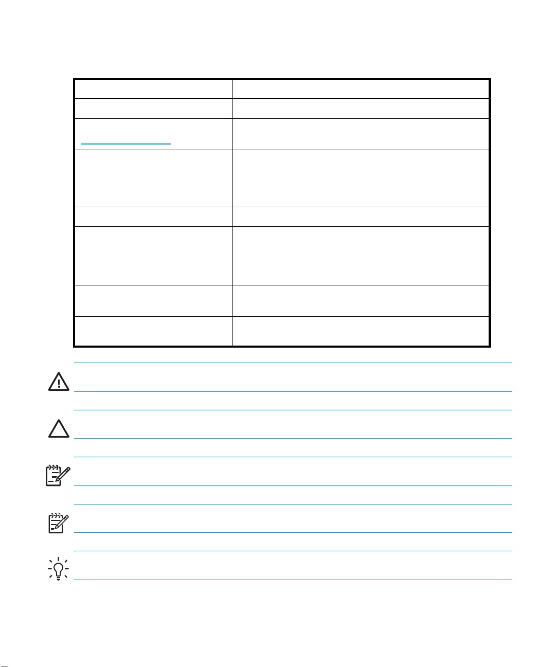
1 Document conventions . . . . . . . . . . . . . . . . . . . . . . . . . . . . . . . . . . . . . . . . . . . . . . . . 12
2 Ultrium Tape Drive Capacity and Data Transfer Rate . . . . . . . . . . . . . . . . . . . . . . . . . . . 18
3 SDLT Tape Drive Capacity and Data Transfer Rate. . . . . . . . . . . . . . . . . . . . . . . . . . . . . 19
4 Library Status LED . . . . . . . . . . . . . . . . . . . . . . . . . . . . . . . . . . . . . . . . . . . . . . . . . . . 51
5 View Library Options . . . . . . . . . . . . . . . . . . . . . . . . . . . . . . . . . . . . . . . . . . . . . . . . . 61
6 View SCSI Options . . . . . . . . . . . . . . . . . . . . . . . . . . . . . . . . . . . . . . . . . . . . . . . . . . 64
7 View Network Options. . . . . . . . . . . . . . . . . . . . . . . . . . . . . . . . . . . . . . . . . . . . . . . . 68
8 Media Label Identifiers. . . . . . . . . . . . . . . . . . . . . . . . . . . . . . . . . . . . . . . . . . . . . . . . 78
9 Maintenance Menu . . . . . . . . . . . . . . . . . . . . . . . . . . . . . . . . . . . . . . . . . . . . . . . . . . 91
10 Fault Symptom Codes. . . . . . . . . . . . . . . . . . . . . . . . . . . . . . . . . . . . . . . . . . . . . . . . 103
11 Troubleshooting General Problems. . . . . . . . . . . . . . . . . . . . . . . . . . . . . . . . . . . . . . . 136
12 Library Diagnostic Tests . . . . . . . . . . . . . . . . . . . . . . . . . . . . . . . . . . . . . . . . . . . . . . 142
13 Power Specifications . . . . . . . . . . . . . . . . . . . . . . . . . . . . . . . . . . . . . . . . . . . . . . . . 159
14 Rackmount Model Mechanical Specifications . . . . . . . . . . . . . . . . . . . . . . . . . . . . . . . 159
15 Operating Environmental Specifications . . . . . . . . . . . . . . . . . . . . . . . . . . . . . . . . . . . 160
16 Packed or Unpacked Environmental Specifications. . . . . . . . . . . . . . . . . . . . . . . . . . . . 160
17 Transit -- Short Term Environmental Specifications . . . . . . . . . . . . . . . . . . . . . . . . . . . . 160
18 Acoustic Noise Declared per ISO 9296 and ISO 7779 . . . . . . . . . . . . . . . . . . . . . . . . 161
19 Schallemissionswerte - Werteangaben nach ISO 9296 und ISO 7779/DIN 27779 . . . . 161
20 Regulatory and Product Safety Certifications . . . . . . . . . . . . . . . . . . . . . . . . . . . . . . . . 161
MSL6000 series tape library user guide 9
Page 10

10
Page 11

About this guide
This guide provides information about:
• Becoming familiar with library components.
• Installing the library.
• Configuring the library.
• Operating the front panel.
• Using the remote management interface.
• Performing maintenance procedures.
• Troubleshooting the library.
Related documentation
In addition to this guide, please refer to other documents for this product:
• HP StorageWorks MSL Series Pass-Through Mechanism Reference Guide
• HP StorageWorks Network Storage Router User Guide
These and other HP documents can be found on an HP web site: http://www.docs.hp.com
.
MSL6000 series tape library user guide 11
Page 12
Document conventions and symbols
Table 1 Document conventions
Convention Element
Medium blue text: Figure 1
Medium blue, underlined text
(http://www.hp.com)
Bold font
Italics font
Monospace font
Monospace, italic font
Monospace, bold font
Cross-reference links and e-mail addresses
Web site addresses
• Key names
• Text typed into a GUI element, such as into a box
• GUI elements that are clicked or selected, such as menu
and list items, buttons, and check boxes
Text emphasis
• File and directory names
• System output
• Code
• Text typed at the command-line
• Code variables
• Command-line variables
Emphasis of file and directory names, system output, code, and
text typed at the command-line
WARNING! Indicates that failure to follow directions could result in bodily harm or death.
12
CAUTION: Indicates that failure to follow directions could result in damage to equipment or data.
IMPORTANT: Provides clarifying information or specific instructions.
!
NOTE: Provides additional information.
TIP: Provides helpful hints and shortcuts.
Page 13

HP technical support
Telephone numbers for worldwide technical support are listed on the HP web site:
http://www.hp.com/support/
Collect the following information before calling:
• Technical support registration number (if applicable)
• Product serial numbers
• Product model names and numbers
• Applicable error messages
• Operating system type and revision level
• Detailed, specific questions
For continuous quality improvement, calls may be recorded or monitored.
HP strongly recommends that customers sign-up online using the Subscriber's choice web site at
http://www.hp.com/go/e-updates
• Subscribing to this service provides you with e-mail updates on the latest product enhancements,
newest versions of drivers, and firmware documentation updates as well as instant access to
numerous other product resources.
• After signing-up, you can quickly locate your products by selecting Business support, and then
Storage under Product Category.
HP-authorized reseller
.
.
For the name of your nearest HP-authorized reseller:
• In the United States, call 1-800-345-1518.
• Elsewhere, visit http://www.hp.com
numbers.
Helpful web sites
For product information, see the following web sites:
• http://www.hp.com
• http://www.hp.com/go/storage
• http://www.hp.com/support/
• http://www.docs.hp.com
• http://www.hp.com/go/ebs
and click Contact HP to find locations and telephone
MSL6000 series tape library user guide 13
Page 14

14
Page 15
1Introduction
Designed for backup operations with high-end networks and high-performance servers, the HP
StorageWorks MSL 6000 Series tape libraries are the next generation performers in high-volume
backup and archival service. The libraries also feature high availability, maximum storage density,
and easy serviceability.
The library SCSI interface-to-host system supports Low Voltage Differential (LVD). The tape drives and
the robotics control functions each use separate SCSI connections and SCSI ID addresses. Library
SCSI I/O is provided through two VHDCI-series, 68-pin, Micro-D SCSI connectors located at the
rear of the unit on each tape drive. Robotics SCSI I/O is provided through two VHDCI-series,
68-pin, Micro-D SCSI connectors located on the library controller board.
The remainder of this chapter describes the major components of the library, including:
• Models, page 15
• Accessories, page 16
• Tape Drives, page 16
• Magazines, page 21
• Power Supplies, page 22
• Robotics, page 23
• Library Controller Board, page 23
• Factory-Defined Accessory PCI Slots, page 25
• Front Panel Indicators, page 26
• Multi Unit Library Systems, page 27
Models
The MSL Series tape library family includes the following models:
• Two-drive models:
• Four-drive models:
NOTE: MSL6030/MSL6060 libraries operate with Ultrium LTO drive technology;
MSL6026/MSL6052 libraries operate with SDLT drive technology.
• MSL6030
•MSL6026
• MSL6060
•MSL6052
MSL6000 series tape library user guide 15
Page 16

NOTE: Two-drive models are 8.75 in (22.23 cm) in height, sometimes referred to as 5U. Four-drive
models are 17.50 in (44.45 cm) in height, sometimes referred to as 10U.
Any MSL Series tape library can operate as a standalone unit or can be installed in a rack to form
a larger integrated multi unit library configuration. MSL6030/MSL6026 libraries contain up to two
tape drives, two removable tape cartridge magazines, and robotics capable of random or
sequential tape cartridge operation. MSL6060/MSL6052 libraries contain up to four tape drives,
four removable tape cartridge magazines, and robotics capable of random tape cartridge
operation.
NOTE: Throughout this manual, MSL6030/MSL6026 libraries will be referred to as two-drive
models. MSL6060/MSL6052 libraries will be referred to as four-drive models.
Accessories
Contact your authorized service provider or visit the HP website at
for the most current list of accessories that are available for an MSL Series library.
Tape Drives
MSL Series tape libraries support up to four tape drives (see Figure 1). SCSI I/O is accomplished
through two VHDCI-series, 68-pin, Micro-D SCSI connectors located at the rear of the library on
each tape drive. The drives are numbered beginning with 0: the first tape drive is Drive 0, the
second is Drive 1, etc.
http://www.hp.com/go/autom ation
Introduction16
Page 17

1 Tape Drive 0
2 Tape Drive 1
Figure 1 Library tape drive locations
CAUTION: It is critical to ensure that the media you use matches the format of your tape drive.
Cleaning cartridges and formatted data cartridges are unique for each drive technology. Damage
may occur if inappropriate media is used in tape drives.
NOTE: If using mixed media, ensure your software application supports it.
NOTE: SDLT 600, Ultrium 1840, Ultrium 960, and Ultrium 460 tape drives do not offer hot-plug
capability.
Ultrium Tape Drives
The Ultrium tape drive is a high-performance streaming tape drive that uses Linear Tape-Open (LTO)
technology. An Ultrium 460 tape drive is capable of storing up to 200 GB (native) or 400 GB (2:1
compression) of data per cartridge. An Ultrium 960 tape drive is capable of storing up to 400 GB
(native) or 800 GB (2:1 compression) of data per cartridge. An Ultrium 1840 tape drive is capable
of storing up to 800 GB (native) or 1600 GB (2:1 compression) of data per cartridge. Access the
HP StorageWorks Ultrium Tape Drive User’s Guide from
information about its features and capabilities.
3 Tape Drive 2
4 Tape Drive 3
http://www.hp.com/support
for more
MSL6000 series tape library user guide 17
Page 18
Table 2 Ultrium Tape Drive Capacity and Data Transfer Rate
Drive Model Data Capacity Sustained Data Transfer Rate
Ultrium 460 200 GB (native)
30 MB/sec (216 GB/hour)
400 GB (compressed)
Ultrium 960 400 GB (native)
800 GB (compressed)
Ultrium 1840 800 GB (native)
1600 GB (compressed)
NOTE: Compressed capacity assumes a 2:1 compression ratio.
Ultrium Tape Cartridges
NOTE: In addition to the information provided in this manual, refer to the documentation provided
with your media for more information. Also see ”Maintaining Tape Cartridges” on page 92.
CAUTION: HP Ultrium tape drives require special cleaning cartridges and data cartridges
formatted specifically for HP Ultrium. To avoid damage to your tape drive, it is critical to use
appropriate cleaning cartridges, and properly formatted data cartridges.
60 MB/sec (432 GB/hour)
80 MB/sec (576 GB/hour)
160 MB/sec (1152 GB/hour)
120 MB/sec (864 GB/hour)
240 MB/sec (1728 GB/hour)
Approved media will have the Ultrium format trademark which indicates that the media has passed
Ultrium format compliance testing (see Figure 2 for an example of the Ultrium 3 format trademark).
Figure 2 HP Ultrium 960 format trademark
For best results, always use HP branded media. For data and cleaning cartridges for your tape
library, see www.hp.com/go/media
CAUTION: Do not bulk erase Ultrium formatted cartridges. This will destroy pre-recorded servo
information and make the cartridge unusable.
Introduction18
Page 19
Make it a practice to visually inspect your tape cartridges when loading or removing them from your
tape library. Taking a few minutes to check the condition of your cartridges will lower the risk of
repeated failures and help ensure uninterrupted backup.
CAUTION: Always discard damaged tape cartridges. If a defective tape cartridge is loaded into a
tape drive, it may in turn damage the drive, potentially requiring drive replacement.
NOTE: For information on labeling tape cartridges, see ”Labeling Tape Cartridges” on page 75.
SDLT Tape Drives
NOTE: In addition to the information provided in this manual, refer to the documentation provided
with your media for more information. Also see Chapter 7, ”Troubleshooting” beginning on
page 101.
The SDLT tape drive is a high-capacity, high-performance streaming tape drive that uses Laser
Guided Magnetic Recording (LGMR) technology to maximize the amount of data that can be stored
on a tape. An SDLT 320 tape drive is capable of storing up to 160 GB (native) or 320 GB (2:1
compression) of data per cartridge. An SDLT 600 tape drive is capable of storing up to 300 GB
(native) or 600 GB (2:1 compression) of data per cartridge. Access the HP StorageWorks SDLT Tape
Drive Reference Guide from
capabilities.
http://www.hp.com/support
for more information about its features and
Table 3 SDLT Tape Drive Capacity and Data Transfer Rate
Drive Model Data Capacity Sustained Data Transfer Rate
SDLT 160/320 160 GB (native)
320 GB (compressed)
SDLT 300/600 300 GB (native)
600 GB (compressed)
NOTE: Compressed capacity assumes a 2:1 compression ratio.
16 MB/sec (115.2 GB/hour)
32 MB/sec (230.4 GB/hour)
36 MB/sec (259.2 GB/hour)
72 MB/sec (518.4 GB/hour)
MSL6000 series tape library user guide 19
Page 20
SDLT Tape Cartridges
NOTE: In addition to the information provided in this manual, refer to the documentation provided
with your media for more information.
CAUTION: SDLT tape drives require special cleaning cartridges and data cartridges formatted
specifically for SDLT. To avoid damage to your tape drive, it is critical to use appropriate cleaning
cartridges, and properly formatted data cartridges.
Make it a practice to visually inspect your tape cartridges when loading or removing them from your
tape library. Taking a few minutes to check the condition of your cartridges will lower the risk of
repeated failures and help ensure uninterrupted backup.
CAUTION: Always discard damaged tape cartridges. If a defective tape cartridge is loaded into a
tape drive, it may in turn damage the drive, potentially requiring drive replacement.
NOTE: For information on labeling tape cartridges, see ”Labeling Tape Cartridges” on page 75.
Introduction20
Page 21

Magazines
MSL Series tape libraries contain two or four removable tape cartridge magazines that are
accessible through the front doors (see Figure 3).
1
2
1
1
2
2
1 Left Magazine(s), with integrated mail slot
2 Right Magazine(s)
Figure 3 Library magazines
Looking from the front of the library, each left tape magazine includes a mail slot, which is
accessible when that magazine door is open. When this mail slot pivots forward, you can insert or
remove a single tape without having to unlock, remove, and reinventory the magazine. If a full tape
cartridge magazine is required, the library can be reconfigured to recognize each mail slot as a
standard data slot. The right tape magazine contains fixed cartridge slots (no mail slot feature), so it
retains its full capacity at all times.
NOTE: The slots and mail slots are numbered beginning with 0: the first slot is Slot 0, the second is
Slot 1, etc. SDLT magazine maximum capacity is 26 slots; LTO magazine maximum capacity is 30
slots.
MSL6000 series tape library user guide 21
Page 22
Power Supplies
MSL Series tape libraries support one or two power supplies depending upon the model (see
Figure 4). These auto-ranging power supplies are capable of using any nominal AC voltage
between 100 VAC and 240 VAC power, at 50 Hz or 60 Hz.
Power to the library is supplied through AC connectors at the rear panel of each power supply
receiver. Library power is normally controlled from the graphical user interface (GUI) touch screen;
however, a manual power disconnect switch is located at the rear of each power supply.
CAUTION: The power supply is generally not to be removed by the operator. Hazardous voltage is
present in the cavity if the power cord is not removed. If a faulty power supply exists, contact your
authorized service provider.
For the four-drive models, two power supplies are supported to provide redundancy for mission
critical operations. Both power supplies share the load under normal operating conditions, but if
one of the power supplies fails, the remaining power supply assumes the full load (see Figure 4 on
page 22). For the two-drive models, only one power supply is supported.
1 Power Switch
2 Power Supply
Figure 4 Library power supplies
NOTE: For the four-drive models, the left AC power receptacle is for the bottom power supply. The
right AC power receptacle is for the top power supply.
Introduction22
3 AC Power Cord(s)
Page 23
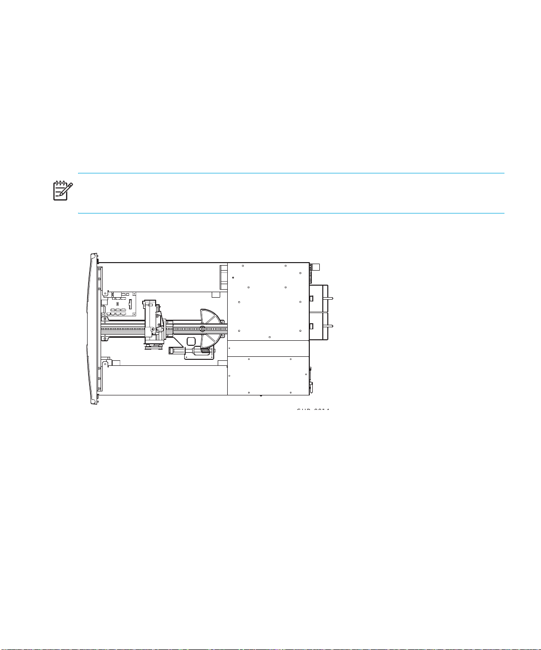
Robotics
MSL Series tape library robotics consist of a cartridge shuttle, motor hardware, motor drives, and
other support electronics (see Figure 5). The four-drive models also contain a vertical axis
mechanism that enables the robotics to travel between the upper and lower tape cartridge
magazines. These robotics are capable of picking and placing tapes throughout a 180-degree arc
that consists of the tape drives, tape cartridge magazines, and an optional Pass-Through
Mechanism (PTM).
The cartridge shuttle assembly includes a mounted bar code reader for scanning labeled tape
cartridges installed in the magazines and tape drives.
NOTE: Both full bar code reader scan and physical scan are conducted each time the library is
initially powered up, or each time a tape magazine is accessed using normal operational modes.
In four-drive models, the robotic-PTM interface is at the lower vertical axis PTM elevator position only.
Figure 5 Library robotics (top cover removed)
Library Controller Board
The library controller board contains a single microprocessor and associated logic devices to
control all robotics operations and manage overall library functions. The microprocessor enables the
SCSI interface between the library and the host system.
The library controller board is installed in a card cage at the rear of the library. In four-drive models,
the library controller board can be serviced with a #1 Phillips screwdriver (see Figure 6). If a
replacement controller board is needed, contact your authorized service provider. Step-by-step
MSL6000 series tape library user guide 23
Page 24
procedures will be included with the replacement. In two-drive models, the library controller board
cannot be removed.
.
1 Library Controller Board
2 Factory-Defined Accessory PCI Slots (up to 5)
Figure 6 Library controller board
NOTE: The library controller board is not removable in two-drive libraries.
Introduction24
Page 25
NOTE: For MSL Series libraries, the library controller board must be installed in the right-hand slot
of the card cage area (upper card cage area for the four-drive models). The remaining slots on the
library do not support the connections that are required for the library controller board to operate
correctly.
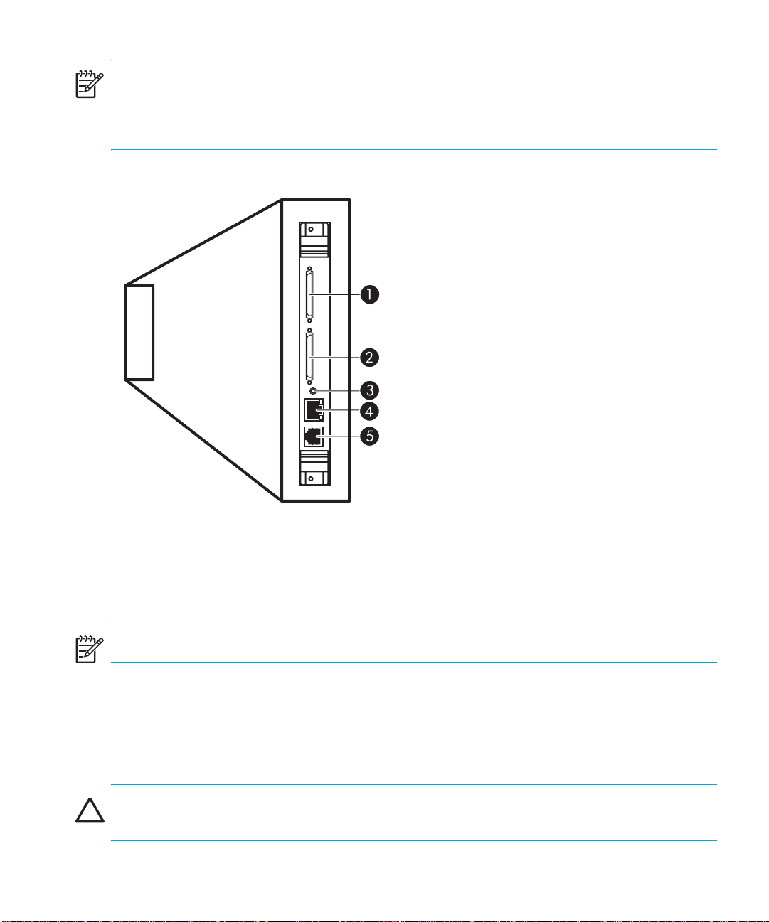
.
1 SCSI VHDCI connector
2 SCSI VHDCI connector
3 Mode toggle switch
4 Ethernet RJ-45 connector
5 Serial RS232 connector
Figure 7 Library controller board connections
NOTE: The mode toggle switch is not active.
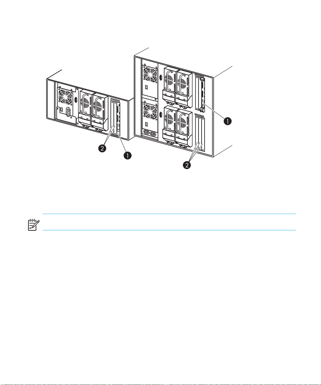
Factory-Defined Accessory PCI Slots
MSL Series tape libraries contain one or two rear-access card cages, and one or two 32-bit,
33-MHz Compact PCI backplanes (see Figure 8). These backplanes contain the plug-in connectors
for a library controller board, and up to five optional HP-defined PCI add-in cards.
CAUTION: Use of non-HP qualified PCI option cards can damage your MSL Series library and will
void product warranty. Follow all operating instructions shipped with the optional card upgrade kit.
MSL6000 series tape library user guide 25
Page 26
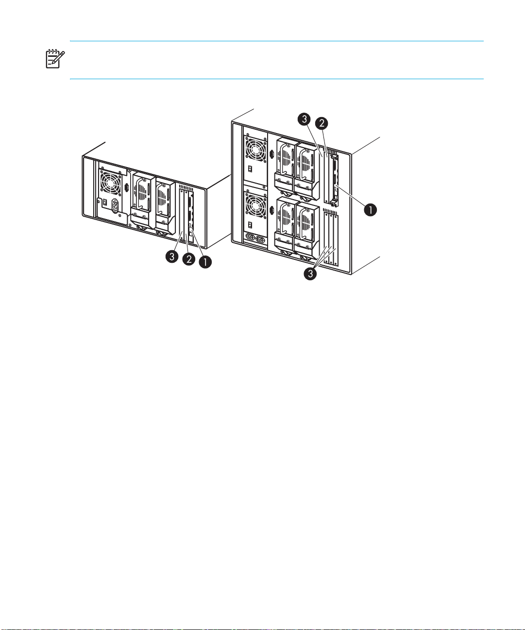
NOTE: The library controller board must be installed in the right slot of the card cage area (upper
card cage area for the four-drive models).
1 Library Controller Board
2 Optional Embedded Fibre Channel Board
Figure 8 Library card cages
3 Factory-Defined Accessory PCI Slots (up to 5)
Embedded Network Storage Router (Optional)
Some library models ship with an optional embedded Network Storage Router in the slot next to the
library controller board.
This board provides bidirectional connectivity in a Fibre Channel Switched Fabric supporting Fibre
Channel and SCSI devices. See ”Optional Fibre Channel Card” on page 167 for additional
information on configuring and using the optional Fibre Channel board.
Front Panel Indicators
The library front panel indicators consist of the following:
• Viewing window—Lets you visually check the internal operations of the library.
• GUI touch screen—Manually operated to set up and configure the library.
• Library status LED—Displays the library operational status of the library.
Introduction26
Page 27
1
2
3
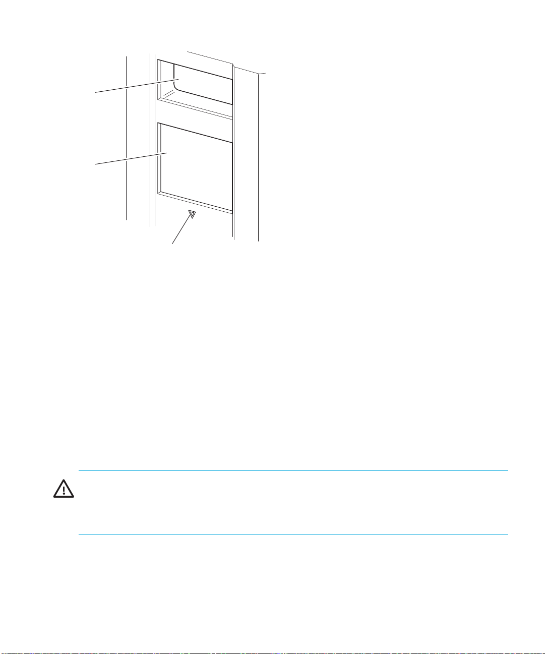
Figure 9 Library front panel
Multi Unit Library Systems
MSL Series tape libraries can be stacked in a scalable combination with additional two-drive and
four-drive models to form a multi unit library configuration. Through use of a rear-mounted
Pass-Through Mechanism (PTM), all libraries in a multi unit library configuration can operate
together as a single virtual library system. Stacked libraries are interconnected through their rear
panel Ethernet connections to a supplied LAN hub that mounts to the rack enclosure. The LAN hub
also provides a wide area network (WAN) connector when libraries are combined in their
maximum stacked height.
1 Viewing Window
2 GUI Touch Screen
3 Library Status LED
A maximum of four four-drive models or eight two-drive models can be connected together in this
manner. Any combination of libraries, not exceeding 40 Units (40U) in total stacked height, can
also be used. A multi unit library configuration appears as a single library to the host computer
system and application software. For multi unit applications, the top library becomes the master unit
and all other libraries are slave units.
WARNING! The PTM continues to function each time a slave library is physically removed from the
rack enclosure configuration during normal library operation. Refer to the HP StorageWorks MSL
Series Pass-Through Mechanism Reference Guide for detailed installation, configuration, and
operation information
The library robotics can pick and place tape cartridges into a movable elevator that encompasses
the full length of the PTM. In this manner, individual tapes can be passed up or down between the
libraries contained in the multi unit library configuration under the master library control. Robotics
.
MSL6000 series tape library user guide 27
Page 28
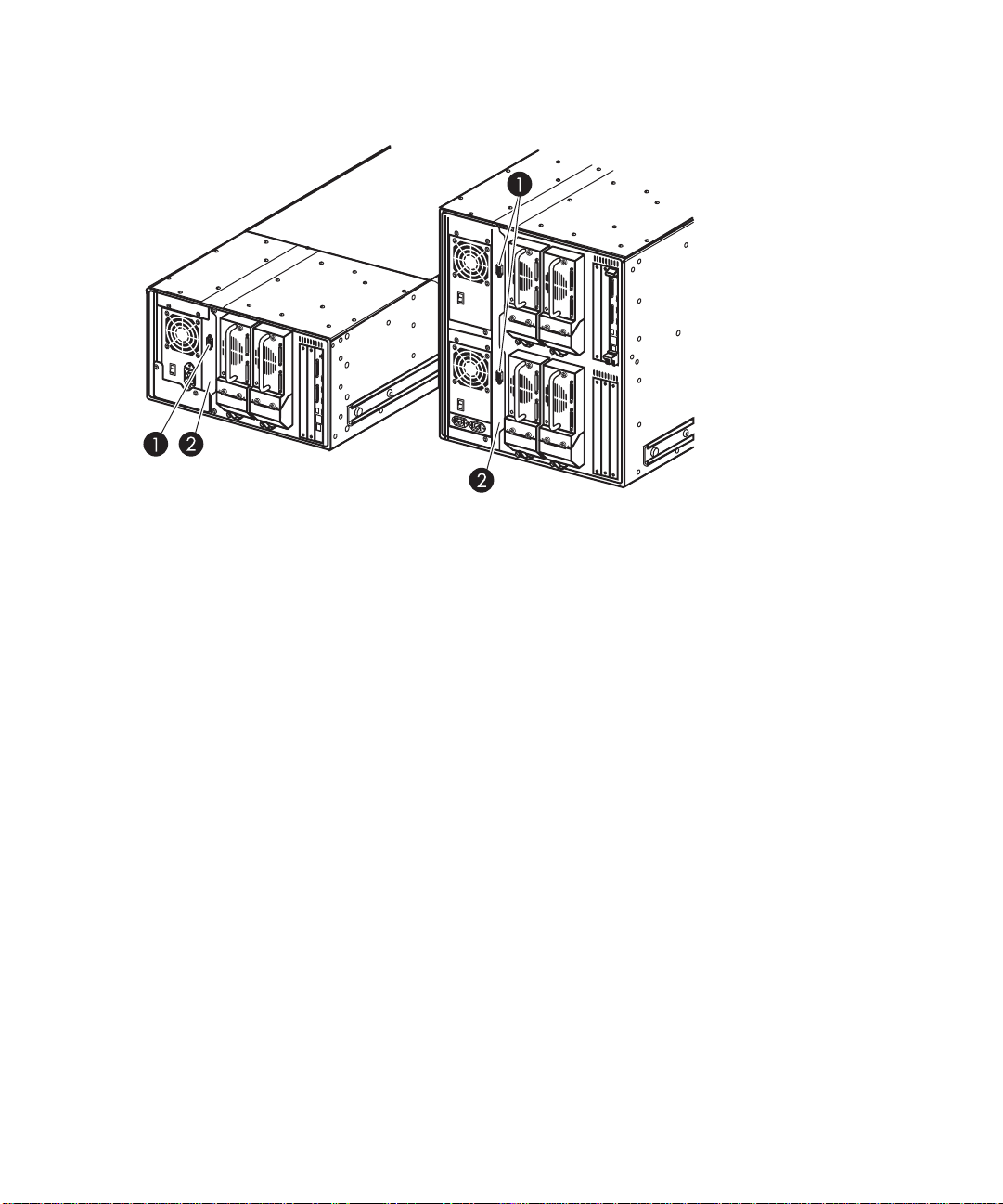
access to the PTM is located at the rear of the library beneath the PTM cover (see Figure 10 on
page 28).
1 PTM Interface Connector
2 PTM Mounting Cover (removal required for PTM installation)
Figure 10 Library PTM mounting location
Introduction28
Page 29
2 Installation
This chapter explains how to install an HP StorageWorks MSL Series tape library. Sections in this
chapter include:
• Converting a Tabletop Model to a Rackmount Model, page 29
• Setting Up the Rackmount Model, page 30
• Converting a Rackmount Model to a Tabletop Model, page 34
• Applying Power to the Library, page 35
• Cabling for SCSI Configurations, page 36
NOTE: Be sure to keep and store all shipping materials from your MSL Series tape library for
potential future use.
Converting a Tabletop Model to a Rackmount Model
To make a tabletop library ready for rack enclosure installation:
1. Remove the rubber feet.
2. Remove the cover.
3. Attach the inner rails to the library using the supplied Allen wrench and screws. Tighten the
screws until snug.
MSL6000 series tape library user guide 29
Page 30

Figure 11 Converting a tabletop model (four-drive model shown)
Setting Up the Rackmount Model
WARNING! To reduce the risk of personal injury or damage to the equipment, be sure that:
• The leveling jacks are extended to the floor.
• The full weight of the rack rests on the leveling jacks.
• In single rack installations, the stabilizing feet are attached to the rack.
• In multiple rack installations, the racks are coupled.
• Only one rack component is extended at any time. A rack may become unstable if more than
one rack component is extended for any reason.
Setting up the rackmount model requires a template, rack enclosure slide rails, and two people or a
mechanical lift to physically install the library in a rack enclosure.
To set up the rackmount model:
1. Use the template that shipped with the library to mark the location of the mounting hardware on
the mounting rails of the rack enclosure (see Figure 12). The black dots along the sides of the
template indicate the top of a U.
Installation30
Page 31

Figure 12 Library template (10000 rack enclosure shown)
NOTE: For HP rack system/e and AlphaServer H9A rack enclosures, refer to the appropriate rack
rail adapter kit.
2. Remove the template and then attach the rails using the supplied fasteners (see Figure 12). The
front rail brackets are threaded to directly accept screws. The rear brackets are not threaded and
require cage/clip nuts in the rack enclosure rear vertical rails.
NOTE: Refer to the Compaq Rack Products Reference Guide for detailed cage nut installation
instructions on 10000 racks.
NOTE: Fully tighten the front rail screws. Leave the rear rail screws “finger tight” to prevent binding
when mounting the library.
a. Fully extend the slide rails X on both sides of the rack enclosure until they lock.
b. Slide the inner guide rail Y as far as possible to the front of the rail assembly.
MSL6000 series tape library user guide 31
Page 32

2
1
Figure 13 Installing the rails
3. Install the two slide-on clip nuts (previously marked using the template, two holes above the top
bracket screw holes) on each of the front rack enclosure vertical rails (Figure 13).
WARNING! Two people should perform the next step. Make certain, when the library is fully
extended, that a force of 20% of the rack enclosure’s weight, but not more than 57 pounds (26 kg),
applied in any direction other than upwards, does not cause the rack enclosure to overbalance.
CAUTION: The library is heavier toward the tape drive end (rear).
4. Using two people, lift the library and visually align the inner and intermediate slide rails.
5. Carefully insert the library’s inner slide rails Z into the extended intermediate slide rails Y (see
Figure 14).
6. Slide the library into the rack enclosure until the rail locks are engaged.
WARNING! A rack enclosure might become unstable if more than one library is extended for any
reason. Extend only one library at a time.
7. Push in on the rail locks to release the library and slide the library completely into the rack
enclosure.
8. Fully tighten the rear rail screws.
Installation32
Page 33

Figure 14 Installing the library (two-drive model shown)
9. Remove the tape to open the doors for installation.
10.Remove and discard the pull-tabs used to block the latch mechanism.
NOTE: Do not close the doors. You must have access to the retaining screws to complete the
installation. (If necessary, see Chapter 4, ”Operation” on page 49 for information on how to
manually open the library doors.)
11.With the doors open, secure the front panel to the rack enclosure using the retaining screws (see
Figure 15).
12.Close the doors. You can now cable the library.
MSL6000 series tape library user guide 33
Page 34

1 Left Retaining Screw
2 Right Retaining Screw
Figure 15 Securing the library
NOTE: Two-drive libraries require four retaining screws; four-drive libraries require two retaining
screws.
Converting a Rackmount Model to a Tabletop Model
Converting to a tabletop model requires a tabletop conversion kit and two people or a mechanical
lift to physically install the library into the tabletop base.
To make a two-drive library ready for tabletop use:
1. Position the tabletop base at the desired installation location.
2. Lift the library and place it on the base.
3. Place the top cover over the library and slide the locking tabs into the slots in the base.
4. Slide the cover forward into place.
5. Tighten the two thumb screws at the back of the library to lock the two parts together.
6. Tighten the four rack mount fasteners at the front of the library to secure it in the case.
Installation34
Page 35

Figure 16 Converting a rackmount model (two-drive model shown)
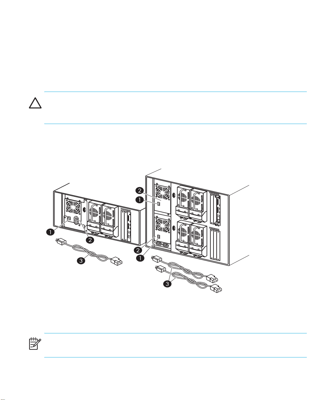
Applying Power to the Library
To apply power to the library (see Figure 17):
1. Connect each supplied power cord X to each power supply receptacle.
NOTE: For four-drive models only, the left-hand AC power receptacle is for the bottom power
supply. The right-hand AC receptacle is for the top power supply.
2. Toggle each power switch Y on.
MSL6000 series tape library user guide 35
Page 36

NOTE: You can remove the appliqué from the GUI touch screen by catching one corner and
carefully lifting it.
3. Wait for power to come on and graphical user interface (GUI) touch screen Z to activate the
display.
1
Figure 17 Applying power to the library (four-drive rackmounted library shown)
Cabling for SCSI Configurations
This section describes supported SCSI cable configurations for the library.
The following SCSI configurations are detailed in this section:
• Two tape drives, dual host system (MSL6030/MSL6026)
• Four tape drives, dual host system (MSL6060/MSL6052)
NOTE: MSL Series libraries support SCSI cable configuration for one to four hosts and one to four
tape drives. Contact your authorized reseller for a list of supported configurations.
NOTE: Host cables are not supplied with the MSL Series library.
Installation36
Page 37

See Appendix D, ”Configuration Examples” beginning on page 165 for a complete listing of
potential configurations.
Supported SCSI Cables
NOTE: For optimum performance, a maximum of one tape drive per SCSI bus is recommended for
Ultrium 460, Ultrium 960, and Ultrium 1840 tape drives.
Each of the tape drives and the library controller constitute an independent SCSI target. When any
two or more devices are connected to the same SCSI bus, each separate SCSI device must be
assigned a unique SCSI ID. For information on assigning SCSI IDs, see Chapter 3, ”Library
Configuration” on page 39.
NOTE: SCSI IDs are set at the factory. If you want to change any of the firmware defaults, you can
do so using the GUI touch screen.
To connect a library to a host system, the host system must have at least one Wide LVD controller
and the appropriate driver software.
Two Tape Drives, Dual Host System
Figure 18 shows a typical SCSI cable configuration for a library with two tape drives installed using
a dual host system.
1 SCSI Terminator
2 0.5 m cable (to library controller card)
Figure 18 MSL6030/MSL6026 library SCSI cable configuration (two tape drives, dual host system)
3 Host cable (Bus 1, to host system)
4 Host cable (Bus 0, to host system)
MSL6000 series tape library user guide 37
Page 38

Four Tape Drives, Dual Host System
Figure 19 shows a typical SCSI cable configuration for a library with four tape drives installed using
a dual host system.
1
4
3
65
2
1
11
1 SCSI Terminator
2 0.5 m cable (to library controller card)
3 Host cable (Bus 1, to host system)
4 Host cable (Bus 3, to host system)
5 Host cable (Bus 2, to host system)
6 Host cable (Bus 0, to host system)
Figure 19 MSL6060/MSL6052 library SCSI cable configuration (four tape drives, dual host system)
NOTE: Daisy-chaining Ultrium 1840, 960 and 460 drives is not recommended due to degraded
performance.
CAUTION: Use the 19.8-inch (0.5m) cable Y to connect the tape drive and the library controller
board.
Installation38
Page 39

3 Library Configuration
This chapter explains how to configure an HP StorageWorks MSL Series tape library for normal
operation. Sections in this chapter include:
• Changing Default Configuration Settings, page 39
• Setting a SCSI ID, page 39
• Setting Up a Reserved Slot, page 41
• Configuring the Network Settings, page 47
Changing Default Configuration Settings
For most applications, you do not have to change the default settings; however, if you do need to
change a configuration setting, use the procedures provided in the following sections. If you are
uncertain whether you need to change a setting, contact your authorized service provider.
Configuration settings that might need to be changed include:
• Setting a SCSI ID, page 39
• Setting Up a Reserved Slot, page 41t
• Configuring the Network Settings, page 47
Change configuration settings using the graphical user interface (GUI) touch screen. For a complete
description of how the GUI touch screen works, see Chapter 4, ”Operation” on page 49.
Setting a SCSI ID
Each tape drive installed in the library requires a unique SCSI ID. The information provided in this
section shows you how to set a SCSI ID.
To set a SCSI ID:
1. Turn the library on and wait until the Power-On Self Test (POST) concludes and the Status
screen is displayed.
2. Select the Menu option.
3. Select SCSI in the Edit Options area to display the following screen.
MSL6000 series tape library user guide 39
Page 40

Figure 20 SCSI option selection screen (two-drive model shown)
NOTE: You can move to the next sequential SCSI options screen by touching the T.
For example, to set the Drive 0 Bus ID to 3:
a. Select the box next to the text “Drive 0 Bus ID:.” The resulting screen (see Figure 21) displays
the current Drive 0 Bus ID along with the new value that you request.
Figure 21 Drive 0 bus ID screen
b. Touch the block that contains the number 3. This places your request into the New data
field.
c. Touch the Save option to confirm your request. A confirmation screen is displayed (see
Figure 22).
Library Configuration40
Page 41

Figure 22 SCSI ID confirmation screen
d. Touch OK to confirm. A new SCSI ID now appears in the Drive 0 Bus ID data field (see
Figure 23).
Figure 23 Drive 0 bus ID data field screen (two-drive model shown)
4. Repeat this procedure to set any remaining SCSI IDs.
IMPORTANT: Do not set duplicate IDs, all SCSI IDs must be unique.
!
5. Touch the Back button repeatedly to return to the Main menu screen.
Setting Up a Reserved Slot
Use this option to designate one or more tape cartridge data storage slots as a cleaning slot, or to
reduce the number of storage elements visible to the application software (for licensing reasons).
MSL6000 series tape library user guide 41
Page 42

NOTE: Reserved slots may be incompatible with some application software.
Reserved Slot Numbering
Standard tape cartridge slots are numbered from the front of the magazine to the rear (see
Figure 24 through Figure 27). If you reserve one slot, it becomes Cleaning Slot #0 in the last slot of
the last magazine. Additional reserved slots continue in this front-to-rear pattern.
#11
#10
#9
#8
#7
#6
#5
#4
#3
#2
4
#1
#0
#24
#23
#22
#21
#20
#19
#18
#17
#16
#15
#14
#13
#12
1
2
3
1 Cleaning Slot #2
2 Cleaning Slot #1
Figure 24 Reserved slot locations, SDLT
Library Configuration42
3 Cleaning Slot #0
4 Mail Slot (Left Magazine Only, If Configured)
Page 43

1
#13
#12
#11
#10
#9
#8
#7
#6
#5
#4
#3
#2
4
#1
#0
#28
#27
#26
#25
#24
#23
#22
#21
#20
#19
#18
#17
#16
#15
#14
2
3
1 Cleaning Slot #2
2 Cleaning Slot #1
3 Cleaning Slot #0
4 Mail Slot (Left Magazine Only, If Configured)
Figure 25 Reserved slot locations, Ultrium (MSL6030)
MSL6000 series tape library user guide 43
Page 44

1
#36
#35
#34
#33
#32
#31
#30
#29
#28
#27
4
#26
#25
#49
#48
#47
#46
#45
#44
#43
#42
#41
#40
#39
#38
#37
2
3
1 Cleaning Slot #2
2 Cleaning Slot #1
Figure 26 Reserved slot locations, lower module, SDLT
3 Cleaning Slot #0
4 Mail Slot (Left Magazine Only, If Configured)
Library Configuration44
Page 45

1
#42
#41
#40
#39
#38
#37
#36
#35
#34
#33
#32
#31
4
#30
#29
#57
#56
#55
#54
#53
#52
#51
#50
#49
#48
#47
#46
#45
#44
#43
2
3
1 Cleaning Slot #2
2 Cleaning Slot #1
3 Cleaning Slot #0
4 Mail Slot (Left Magazine Only, If Configured)
Figure 27 Reserved slot locations, lower module, Ultrium (MSL6060)
To reserve a slot:
1. On the Menu screen, touch the Library option in the Edit Options area.
2. On the Library options screen, press the T to scroll to the screen that contains the Total
Reserved Slots option (see Figure 28).
Figure 28 Total reserved slots screen
3. Press the associated box next to the Total Reserved Slots option (see Figure 29).
MSL6000 series tape library user guide 45
Page 46

Figure 29 Reserved slots numeric keypad screen
4. Enter the number of slots to reserve and then press Save to confirm your change. On the
resulting confirmation screen (see Figure 30), press OK to save.
Figure 30 Total reserved slots confirmation screen
5. Press the Back button repeatedly to return to the Main menu screen.
NOTE: Your choice takes effect the next time you boot the library.
NOTE: Changes to this option may require reconfiguring the software application in order to
accommodate the change in storage slots.
Library Configuration46
Page 47

Configuring the Network Settings
The library automatically obtains an IP address from a DHCP server when the library is powered up.
The library also supports user-specified fixed addresses through the front panel. To set a fixed
address:
1. On the Menu screen, touch Network in the Edit Options area.
2. The IP Address Determination screen appears (see Figure 31).
Figure 31 IP address determination screen
3. Touch the IP Address Determination option (see Figure 31) and then the User Specified
IP Address option (see Figure 32).
Figure 32 User-specified IP address screen
4. Touch OK to confirm your selection.
5. Touch each IP Address option and then use the keypad to enter each IP address (see
Figure 33).
6. Save and confirm your selections.
MSL6000 series tape library user guide 47
Page 48

Figure 33 Fixed IP address screen
7. Press the Back button repeatedly to return to the Main menu screen.
NOTE: You must reboot the library for settings to take effect.
Library Configuration48
Page 49

4Operation
This chapter describes how to operate an HP StorageWorks MSL Series tape library. Sections in this
chapter include the following:
• Front Panel, page 49
• Library Display Screens and Options, page 53
• Menu Selections, page 60
• Inserting and Removing Tape Cartridges, page 72
Front Panel
The front panel of the library includes the following (see Figure 34):
• Magazine doors (left- and right-hand)
• Graphical user interface (GUI) touch screen
• Library status LED
• Viewing window
1
1
2
3
4
1 Left-hand Magazine Door
2 Viewing Window
3 GUI Touch Screen
Figure 34 Library front panel
Magazine Doors
The magazine doors have both an electrical release (via the GUI touch screen) and a manual
release. It is always recommended that you open the magazine doors using the GUI touch screen.
However, if the GUI touch screen fails, or if the magazines need to be accessed when power is off,
2
5
3
4
5
4 Library Status LED
5 Right-hand Magazine Door
MSL6000 series tape library user guide 49
Page 50

you can manually open the magazine doors by pushing a small metal pin or paper clip into the
mechanical releases (see Figure 35).
CAUTION: The magazine doors must
only
be opened manually in an emergency. Failure to
follow normal procedures can cause data loss and equipment damage.
NOTE: The library may not perform a complete inventory each time a magazine is manually
removed and then replaced using the emergency release.
1
2
3
31 2
1 Left-hand Magazine Door Release
2 Library Status LED
3 Right-hand Magazine Door Release
Figure 35 Magazine door mechanical releases (emergency access)
Operation50
Page 51

Indicators
The library front panel indicators consist of a GUI touch screen and a library status LED (see
Figure 36 and Table 4).
1
Figure 36 Library indicators
Table 4 Library Status LED
1 GUI Touch Screen
2 Library Status LED
2
Indicator Description
Solid green The library is operating correctly under normal
conditions.
Flashing green The library is operating correctly; however, a change is
being made on the GUI touch screen that interrupts the
current library operation (off-line).
Solid amber The library is in a fault state as detailed by the error
message on the GUI touch screen.
Front Panel and Media Security Locks
The following security features are available to help you avoid accidental interruption of library
operation.
GUI Touch Screen
The GUI touch screen offers three levels of security (see Figure 37):
• User Level 1—allows access to the mail slot(s).
• User Level 2—allows magazine access, mail slot access, SCSI options, diagnostics, and lets you
move media.
MSL6000 series tape library user guide 51
Page 52

• Service—allows access to the administrative menu that lets you view/edit library and SCSI
options.
NOTE: The library ships with a default service password of 5566.
Figure 37 Password levels
Each password is represented by four decimal digits that are stored in NVRAM in a range of 0001
to 9999.
NOTE: 0000 is used to disable password verification for each level.
Enabling a password at a lower level re-enables disabled higher levels to that value. As a result,
prior to accessing any higher level operation, you are prompted first to enter the new higher level
password.
You can also use a higher level password to gain access to a lower level operation. For example,
use the Service password to access the Move Media operation. Using the Service password to
access the Menu option also gives full access (without validating) to the Service operations.
NOTE: To restore passwords if forgotten, use Set User Defaults on the Maintenance screen of the
GUI. Note that any configuration that was previously set will be lost. If necessary, record all
configuration settings before resetting the password.
CAUTION: Do not use Set Factory Defaults or library damage may occur.
Operation52
Page 53

Host System
Media can also be reserved by software running on the host. The library provides no GUI touch
screen override for this command. Usually, exiting the host software restores media access. In the
event of host failure, you can restore media access by cycling the library power.
Library Display Screens and Options
The library GUI touch screen displays graphics and text characters in the form of easy-to-understand
messages. Graphics and text messages, along with their functions, are described in this section.
Initialization Screen
When power is first applied to the library, a series of Power-On Self Test (POST) diagnostics are
performed. After the POST completes, the following initialization screen appears during the library
inventory and scalability configuration.
Figure 38 Initialization screen
Library Status Screen
After the POST executes successfully and the library initialization completes (approximately 45
seconds), the following library Status screen appears (see Figure 39):
1 Technical Support Information (HP logo)
2 LCD Contrast Controls (reset and power-up)
MSL6000 series tape library user guide 53
Page 54

1
2
Figure 39 Library status screen (two-drive model shown)
The library Status screen lets you select the following options:
• Mail Slot Access
• Magazine Access
• Move Media
• LCD Contrast Controls
• Menu
• Online/Offline
• Status
• Power
Operation54
Page 55

Technical Support Information
Selecting this option via the HP logo displays HP-specific technical support assistance information,
including the HP StorageWorks and the HP technical support websites (see Figure 40).
Figure 40 Technical support information screen
Mail Slot Access (Left-hand Magazines Only)
Select this option to display the Mail Slot Access screen (Figure 41). This option provides access
to a mail slot while the library remains powered up. Note that a mail slot is reserved for the first
tape cartridge slot in a left-hand magazine, and can be password protected or fully disabled. If the
mail slot is disabled, this menu button is absent. On four-drive models, solenoids restrict access to
the selected mail slots.
Figure 41 Mail slot access screen (four-drive model shown)
Magazine Access
Select this option to display the Magazine Access screen (Figure 42). For two-drive models, this
option lets you gain access to the left or right-hand magazine doors separately, or both magazine
doors for tape cartridge placement or removal. For four-drive models, this option provides access to
the upper-left, lower-left, or right-hand magazines separately, or both magazine doors for tape
cartridge placement or removal.
MSL6000 series tape library user guide 55
Page 56

NOTE: The Magazine Access option can be password protected.
Figure 42 Magazine access screen (two-drive model shown)
Move Media
Select this option to display the Move Media screen (see Figure 43). The Move Media option
lets you remove a cartridge from a tape drive, a data slot in any magazine, or a mail slot in a
left-hand magazine. This option also lets you load and unload tape cartridges from the installed
tape drives.
See the section on ”Replacing a Cleaning Cartridge in a Reserved Slot” on page 96 for detailed
removal information.
CAUTION: To reduce the risk of drive damage, use SDLT and Ultrium cleaning cartridges only in
their respective drive types.
Operation56
Page 57

CAUTION: Remove media from all drives and slots prior to library transport.
Figure 43 Move media screen (two-drive model shown)
GUI Contrast Controls
Select these options to increase or decrease the contrast of the GUI display (see Figure 39).
Incremental steps are set by adjusting the GUI contrast controls from the library Status screen.
Incremental steps can range from 0 to 31 depending on your preference. These settings are volatile
and are restored to default values upon reboot or power cycling.
Power
Select this option to initiate a library power-down operation. After a successful power-down, a
confirmation message appears (see Figure 44).
NOTE: After you power-down the library, you must power it back up through the GUI display.
NOTE: The library moves the shuttle assembly to the parked position before powering down. This
position is a prerequisite for any library transport.
MSL6000 series tape library user guide 57
Page 58

Status
Figure 44 Power-down confirmation message screen
Select this option to display the information Status screen (Figure 45). From this screen, touch a
magazine icon to display detailed information about the cartridges in that magazine. Touch a drive
icon to view drive ID information, cleaning information, tape cartridge information, and drive status.
Figure 45 Status screen (four-drive model shown)
Operation58
Page 59

Cartridge Map
Selecting this option provides you with a layout of the slots and cartridges that are currently being
used in the library. Bar code labels are displayed if enabled and in use.
Figure 46 Cartridge map screen (two-drive model shown)
Online
Selecting this option places the library online or offline.
NOTE: The library automatically comes online after a power-up initialization. You can use this
option to place the library offline.
Menu
Selecting this option lets you view, configure, and use the library (Figure 47). The Menu option
displays three distinct areas:
• View System Data
• Utilities
• Edit Options
MSL6000 series tape library user guide 59
Page 60

Figure 47 Menu screen
Menu Selections
This section describes the three Menu areas:
• View System Data
• Edit Options
• Utilities
View System Data Area
The View System Data area lets you select the following screens:
• Library Options
• SCSI Options
• Network Options
• Library Info
• Cartridge Map
Library Options
Selecting this option lets you view the library settings. These settings are defined from the Library
option in the Edit Options area (see Figure 48 on page 61).
NOTE: You can move to the next subsequent Library Options screen by selecting the T button.
Operation60
Page 61

Figure 48 View library options screen
Table 5 lists and describes the available Library options.
Table 5 View Library Options
Option Description
Library Remains Offline After
Power-up Initialization
Library does not go online after power-up initialization. You
must select the Online option from the Menu screen on the GUI
touch screen. The default is Disabled.
Auto Power-Up An Installed
Drive After Timeout
Enables a tape drive to be automatically powered up (after a
delay), after replacing a tape drive if you do not explicitly power
up the tape drive from the GUI touch screen. The default is
Enabled.
Unload Mode Lets you determine whether a SCSI MOVE MEDIUM command
is interpreted as Implicit or Explicit. If Implicit, the library unloads
a tape drive before attempting to move a cartridge from that
tape drive. If Explicit, the host must issue a SCSI UNLOAD
command to a tape drive before each MOVE MEDIUM
command that removes a cartridge from that tape drive. The
default is Implicit.
Total Reserved Slots Lets you reduce a specified number of slots at the rear of a
magazine. Some host software imposes size limits on library
magazines for licensing purposes, and does not operate with a
library that exceeds the licensed size. The default is 0.
Auto Clean Mode Lets you enable an automatic tape drive cleaning cycle. To use
this option, you must have reserved a slot for a cleaning
cartridge using the Total Reserved Slots option. The default is
Disabled.
MSL6000 series tape library user guide 61
Page 62

Table 5 View Library Options (continued)
Option Description
Drive and Slot Numbering Lets you specify whether SCSI elements in the library displays
with either zero based or one based. Note that this only affects
the GUI touch screen, not the actual SCSI element addresses. The
default is Zero Based.
Library Mode Lets you set the robotics operating mode to Random, Sequential
Drv0, Sequential Drv n (two or more drives), or Sequential Split.
Sequential Drive n and Sequential Split require two or more
drives in the library. Sequential mode is not available with
multi-module configurations. The default is Random.
Sequential Mode Sequential Mode is locally controlled. Sequential operations
begin with any cartridge loaded into Drive 0. The library
monitors the drive status, and when the host unloads a cartridge
from the drive, it returns the cartridge to the magazine, and then
loads the next cartridge in magazine numerical order. This
operation continues until all cartridges have been loaded, or
until an empty slot is encountered. Two options are available:
Normal (same as Library Mode above) and Recirculate. Instead
of stopping after the cartridge in the last slot for the drive has
been unloaded by the host, Recirculate mode continues the
operation by loading the first cartridge for the drive.
Recirculation will continue until an empty slot is encountered, or
the operator unloads the tape using the GUI touch screen.
LCD Contrast Adjust The LCD contrast controls let you increase or decrease the
contrast of the LCD display. The incremental steps are set by
adjusting the LCD Contrast Adjust option from the Library option.
Incremental steps can range from 0 to 31 depending on your
preference. The default is 16.
Mail-Slot Mode Lets you enable or disable the mail slot(s) in a library. For the
two-drive models, the default is Mail Slot Enabled. For the
four-drive models, the default is Both Mail Slots Enabled.
Barcode Label Size Lets you limit the length of the bar code label. Possible settings
are 1 through 8. The default is 8.
Barcode Label Assignment Lets you specify the alignment of a bar code label. The options
are Left or Right. When used in conjunction with the Barcode
Label Size option, this option strips unwanted trailing characters
(left alignment) or leading characters (right alignment). The
default is Left Align.
Barcode Label Check Digit Lets you specify whether to enable or disable the verification of a
check digit character in the bar code label. The default is
Disabled.
Operation62
Page 63

Table 5 View Library Options (continued)
Option Description
Barcode Reader Lets you enable or disable the bar code reader retries option.
Module Configuration Lets you configure a library for Standalone, Master, or Slave
Library Auto Power-On Mode Lets you enable or disable an automatic library power-on after a
SCSI Options
Selecting this option lets you view the settings defined from the SCSI option in the Edit Options
area (see Figure 49).
NOTE: You can move to the next sequential SCSI Options screen by selecting the T. To return to
the previous SCSI Options screen, select the S or Back button to return to the Menu screen.
The default is Retries Enabled.
operation. The default is Standalone.
power loss without the need to touch the GUI screen. The default
is Enabled.
Figure 49 View SCSI options
Table 6 lists and describes the available SCSI Options selections. (See ”Tape Drives” on page 16
for an illustration of the drive numbering scheme.)
MSL6000 series tape library user guide 63
Page 64

Table 6 View SCSI Options
Option Description
Drive 0 Bus ID Lets you set the SCSI addresses of drive 0. The designators
Drive 0 (outer tape drive) through Drive
n
through
the master unit in a scaled Library system. Default is 1.
Drive 1 Bus ID Lets you set the SCSI addresses of drive 1. The designators
Drive 1 (inner tape drive) through Drive
second through
starting with the master unit in a scaled Library system.
Default is 2.
Drive 2 Bus ID
(four-drive models
only)
Drive 3 Bus ID
(four-drive models
only)
Library SCSI Bus ID Lets you set the SCSI addresses for the library robotics. The
Library SCSI Bus Parity Lets you enable or disable the library robotics SCSI bus
Mail Slot Access This option controls access to the mail slot and media
SCSI Mode Defines the loader as SCSI-2 or SCSI-3. The default is
Unit Attention
Reporting
Lets you set the SCSI addresses of drive 2. The designators
Drive 2 (lower, outer tape drive) through Drive
the third through
starting with the master unit in a scaled Library system.
Default is 3.
Lets you set the SCSI addresses of drive 3. The designators
Drive 3 (lower, inner tape drive) through Drive
the fourth through
starting with the master unit in a scaled Library system.
Default is 4.
default is 0.
parity checking. The default is Enabled.
removal. “Prevent Allow” Command Inhibits allows access
to the mail slot via the GUI control panel and allows
media removal. “Prevent Allow” Command Ignored
prevents access to the mail slot and removal of media. This
option is used for some backup applications. The default is
“Prevent Allow” Command Inhibits.
SCSI-3.
Lets you select reporting of all or only one stacked-unit
attention conditions. If set to Report All, the unit reports all
unit attention conditions in sequence; if set to Report One,
the unit reports only the highest priority condition. The
default is Report All.
th drives, counting from right to left starting with
n
th drives, counting from right to left
n
th drives, counting from right to left
n
th drives, counting from right to left
n
refer to the first
n
refer to the
n
refer to
n
refer to
Operation64
Page 65

Table 6 View SCSI Options (continued)
Option Description
Init Element Status Lets you specify the library’s response to the SCSI
INITIALIZE ELEMENT STATUS command. The
possible settings are No Inventory, Force Inventory, and
Force Label Scan. The default is Force Inventory.
Test Unit Ready
Reporting
Lets you specify the response to a TEST UNIT READY
command if the library is in Sequential Mode. The
possible settings are Standard or Custom. The default is
Custom.
Device Capability Page
Length
Lets you choose between two lengths of the mode
sense/select device capabilities page (SCSI page 1Fh),
which are Short (14 bytes) and Long (18 bytes), to
accommodate different SCSI device implementations of
this page. The default is Short (14 bytes).
Transport Element
Base Address
Storage Element
Base Address
Transfer Element
Base Address
Import/Export Element
Base Address
Product Identification
(PID)
Lets you set the base address for the robotics mechanism.
The default is 0x0.
Lets you set the base address for the magazine slots. The
default is 0x20.
Lets you set the base address for the tape drives. The
default is 0x1E0.
Lets you set the base address for the mail slot. The default
is 0x1C0.
Lets you specify the response of the library’s robotics to the
SCSI INQUIRY command in the Product Identification
field. The default is MSL6000 Series.
Vendor Identification
(VID)
Lets you specify the response of the library’s robotics to the
SCSI INQUIRY command in the Vendor Identification
field. The default is HP.
Post Recovered Errors Lets you specify whether or not recovered errors are
posted. The default is Disabled.
MSL6000 series tape library user guide 65
Page 66

Table 6 View SCSI Options (continued)
Option Description
TapeAlert Mode Specifies conditions for logging and reporting the
following Tape Alert data options. The default is
Unconditionally Generate Recovered Error.
• Logging Disabled: Inhibits the logging
feature.
• No Exceptions: The library must not report
information exceptions.
• Generate Unit Attention: Reports
information exceptions with a Unit Attention
sense key and an ASC/ASCQ of 5D/00.
• Conditionally Generate Recovered Error:
Reports information exceptions with a
Recovered Error sense key and an
ASC/ASCQ of 5D/00, if Recovered Error
Reporting is enabled.
• Unconditionally Generate Recovered
Error: Unconditionally reports information
exceptions with a Recovered Error sense key
and an ASC/ASCQ of 5D/00.
• Generate No Sense: Reports information
exceptions with a No Sense sense key and an
ASC/ASCQ of 5D/00.
• Report on Unsolicited Request Sense:
Reports information exceptions with a No
Sense sense key and an ASC/ASCQ of
5D/00, only in response to an unsolicited
REQUEST SENSE command.
Abort Move Status Lets you specify the SCSI response while aborting a SCSI
command. The possible settings are Busy or Not Ready.
The default is Not Ready.
Door Open Response Lets you specify the SCSI response when a library door is
open. The settings are Ready or Not Ready. The default is
Not Ready.
Initiate Wide Data
Transfer Negotiation
Lets you enable the library to initiate a SCSI synchronous
and wide data transfer negotiation with the host. The
settings are Do Not Initiate or Initiate. The default is Do
Not Initiate.
Operation66
Page 67

Table 6 View SCSI Options (continued)
Option Description
Data Transfer Speed Lets you set the robot or library SCSI data transfer rate to
Report Element Type The default is Disabled.
Fast Terminate
Sequence
Network Options
Selecting this option lets you view the settings defined from the Network option in the Edit
Options area (see Figure 50). Table 7 on page 68 lists and describes the available options.
NOTE: There are no firmware default settings for networks. Contact your network administrator for
specific information on connecting the library to your network.
Synchronous, 10 MB/sec, Synchronous, 5 MB/sec, or
Asynchronous Only. The default is Synchronous, 10
MB/sec.
The default is Disabled.
Figure 50 Default view network options screen
NOTE: The IP Address, IP Mask, IP Gateway, and DNS Server become available after selecting
User Specified IP Address from the Network screen under Edit Options.
MSL6000 series tape library user guide 67
Page 68

Table 7 View Network Options
Option Description
IP Address
Determination
IP Address Lets you select an IP Address.
IP Mask Lets you select an IP Mask.
IP Gateway Lets you select an IP Gateway.
DNS Server Lets you select a DNS server address.
Library Info
Selecting this option lets you display the Miscellaneous Library Info screen (Figure 51). This
screen displays the library’s firmware revision, the local IP and Ethernet address that is currently in
use, the unit serial number, and the library’s power-on hours.
Lets you obtain an IP address from a DHCP server or set a
user specified IP address.
Figure 51 View library info screen
Edit Options Area
The Edit Options area lets you select the following screens:
• Library
• SCSI
• Network
• Passwords
Library
Selecting this option lets you define the Library options used to configure the library for your
specific needs (see Figure 52). Table 5 on page 61 lists and describes the available options.
Operation68
Page 69

SCSI
NOTE: You can move to the subsequent Library screen by selecting the T.
Figure 52 Edit library options screen
Selecting this option lets you define the SCSI options used to configure the library for your specific
needs (see Figure 53). Table 6 on page 64 lists and describes the available options.
NOTE: You can move to the subsequent SCSI screen by selecting the T.
Figure 53 Edit SCSI options screen
MSL6000 series tape library user guide 69
Page 70

Network
Selecting this option lets you define the Network options used to configure the library for your
specific needs (see Figure 54). Table 7 on page 68 lists and describes the available options.
Figure 54 Edit network options screen
Passwords
Selecting this option lets you define the Password options used to configure the library for your
specific needs (see Figure 55). For information on library security features and password levels, see
”Front Panel and Media Security Locks” on page 51.
Figure 55 Edit passwords options screen
Utilities Area
The Utilities area lets you select the following screens:
• Maintenance
• Diagnostics
• Factory
• Security Level
Operation70
Page 71

Maintenance
Selecting this option lets you perform system maintenance on the library (see Figure 56):
Figure 56 Maintenance screen
The Maintenance menu options are described in Chapter 6, ”Maintenance” beginning on
page 91.
Diagnostics
Selecting this option lets you perform a system calibration on available components (see Figure 57).
Available options are dependent on the specified user level.
The Diagnostics menu options are described in Chapter 7, ”Troubleshooting” beginning on
page 101.
Figure 57 Diagnostics screen (four-drive model shown)
MSL6000 series tape library user guide 71
Page 72

NOTE: The Vertical Calibration button is only available on four-drive models.
Factory
The Factory menu options are intended for use by factory personnel only.
CAUTION: Unauthorized use of the Factory option could render the library inoperable.
Security Level
Selecting this option lets you select passwords for a security level (see Figure 58).
NOTE: The library ships with a default Service password of 5566.
NOTE: Setting a value 0000 for a given level disables that level.
Figure 58 Security level screen
Inserting and Removing Tape Cartridges
Unless you are using the mail slot(s), a tape magazine must be removed from the library to remove
or insert tape cartridges. Make sure the slot you want to use is not already reserved for a tape
cartridge or cleaning cartridge that is now in a tape drive. The safest way to do this is to unload all
tape drives before removing a magazine. You can unload all the tape drives either through your
host system software or by using the LOAD/UNLOAD command from the Library Option menu.
Operation72
Page 73

NOTE: Do not add more tape cartridges to the library than its rated slot capacity.
CAUTION: Ultrium and SDLT tape drives require special cleaning cartridges and data cartridges
formatted specifically for the drive technology. To avoid damage to your tape drive, it is critical to
use appropriate cleaning cartridges and properly formatted data cartridges. Contact an HP
authorized dealer or sales representative for current compatibility and availability.
Removing Magazines
Library magazine removal is a manual operation. Access the magazines using the Magazine
Access option from the library Status screen. This option lets you open the left- or right-hand
magazine doors separately, or all magazine doors at the same time. After opening the appropriate
magazine door, pull the magazine out from the library chassis (see Figure 59).
1
2
1
1
1 Left-hand Magazine(s)
2 Right-hand Magazine(s)
Figure 59 Removing tape cartridge magazines
2
2
MSL6000 series tape library user guide 73
Page 74

Inserting Cartridges into a Magazine
A full left-hand magazine is shown in Figure 60. For two-drive models, the lowest numbered tape
cartridge slot Y is the one closest to the front of the left-hand magazine. For four-drive models, the
lowest numbered tape cartridge slot Y is the one closest to the front of the upper-left magazine.
1
3
2
Figure 60 Inserting a tape cartridge (left-hand magazine)
Insert tape cartridges so that the bar code labels are facing outward (see Figure 60).
NOTE: Handle and store tape cartridges in a clean, dust-free environment. Refer to the
documentation provided with your tape cartridges for additional information.
Using Mail Slots (Left-hand Magazines Only)
1 Tape Cartridge
Orientation for
Left-hand Magazine
2 Lowest Numbered
Tape Cartridge Slot
3 Highest Numbered
Tape Cartridge Slot
Mail slots are used only with host system software that supports this feature. The mail slot feature lets
you insert or remove a single tape without removing the entire magazine. The benefit of using a mail
slot is that the magazine does not need to be reinventoried. Access the mail slots using the Mail
Slot Access option from the library Status screen. This option lets you open a left-hand magazine
door for mail slot access. After opening a left-hand magazine door, pivot the mail slot forward to
insert a tape cartridge (see Figure 61).
Operation74
Page 75

NOTE: Mail slots must be enabled (firmware default) using the Mail Slot Mode option from the
Edit Library Options menu. See Table 5 for more information.
NOTE: Disabling a mail slot allows it to be used for an additional data slot, but this may be
incompatible with some host software applications.
1
1 Mail Slot Holder
2 Tape Cartridge
2
Figure 61 Left-hand magazine mail slot (two-drive model shown)
Labeling Tape Cartridges
Attaching a bar code label to each tape cartridge enables the library and application software to
identify the cartridge quickly, thereby speeding up inventory time. Make it a practice to use bar
code labels on your tape cartridges. Your host software may need to keep track of the following
information and the associated bar code:
• Date of format or initialization
• Tape’s media pool
• Data residing on the tape
• Age of the backup
• Errors encountered while using the tape (to determine if the tape is faulty)
MSL6000 series tape library user guide 75
Page 76

CAUTION: The misuse and misunderstanding of bar code technology can result in backup and
restore failures. To ensure that your bar codes meet HP’s quality standards, always purchase them
from an approved supplier and never print bar code labels yourself. For more information, refer to
the order form provided with the library, as well as the Bar Code Label Requirements, Compatibility
and Usage white paper available from
Ultrium Labels
Ultrium tape cartridges have a recessed area located on the face of the cartridge next to the
write-protect switch. Use this area for attaching the adhesive-backed bar code label (see Figure 62).
Do not apply labels onto the cartridge except in this designated area.
CAUTION: The bar code label should be applied as shown in Figure 62 with the alphanumeric
portion facing the hub side of the tape cartridge. Never apply multiple labels onto a cartridge, as
extra labels can cause the cartridge to jam in a tape drive.
http://www.hp.com/support
.
Figure 62 Attaching a bar code label to an Ultrium tape cartridge
Operation76
Page 77

To ensure successful operation of your tape library, place the bar code label entirely within the
recessed area, ensuring that no part of the label is outside of it (see Figure 63).
Figure 63 Proper Ultrium bar code label placement
SDLT Labels
SDLT tape cartridges have a front slide slot located on the face of the cartridge next to the
write-protect switch (see Figure 64 shows) Use this slot for inserting the bar code label by sliding it
into the slot.
CAUTION: Do not apply labels onto the top, bottom, sides, or back of the cartridge as this may
cause damage to the tape drive, or interfere with reliable operation.
MSL6000 series tape library user guide 77
Page 78

Figure 64 Attaching a bar code label to an SDLT tape cartridge
Media Label Identifiers
Be sure to use the proper bar code labels for your drive technology. Table 8 lists the identifier that is
found at the end of 7- or 8-character SDLT and Ultrium bar code labels.
CAUTION: To ensure that your bar codes meet HP’s quality standards, always purchase them from
an approved supplier and never print bar code labels yourself. For more information, refer to the
order form provided with the library, as well as the Bar Code Label Requirements, Compatibility and
Usage white paper available from
Table 8 Media Label Identifiers
Cartridge Type Density Label Identifier
SDLT 320 160/320 GB S or S1
SDLT 600 300/600 GB S or S2
Ultrium 460 200/400 GB L2
Ultrium 960 400/800 GB L3
Ultrium 1840 800/1600 GB L4
http://www.hp.com/support
.
Operation78
Page 79

5Remote Management Interface
Many of the same operations performed from the front panel can also be performed remotely using
the Remote Management Interface. Sections in this chapter include:
• Overview, page 79
• Accessing the Remote Management Interface, page 80
• Using Menu Buttons, page 82
• Changing the Remote Management Interface Passwords, page 88
Overview
The Remote Management Interface lets you monitor and control your automated tape library from
any terminal connected to your network or via the World Wide Web. The Remote Management
Interface hosts a dedicated, protected Internet site that displays a graphical representation of your
library.
After establishing a connection to the library, open any Web browser and enter the IP address of
the library.
NOTE: Be sure that proxy server settings in your browser are disabled
This internet site can be accessed using either Microsoft Internet Explorer (3.0 or higher) or
Netscape (3.0 or higher). The Remote Management Interface shows the overall status of the library
at a glance, and presents a control panel for making adjustments and viewing details down to the
cartridge level.
To use the Remote Management Interface, you must have the following available:
• A 10 BaseT Ethernet Network
• An available IP address (either Internet or local)
• A host computer with COM port (initial setup and alternative maintenance procedures only)
• A computer with a Web browser installed that has access to your network
Two configurations for the Remote Management Interface are available:
• World Wide Accessible.
• Local Area Network
To configure the Remote Management Interface you must set the IP addresses. (For information on
setting IP addresses, see ”Configuring the Network Settings” on page 47.)
MSL6000 series tape library user guide 79
Page 80

CAUTION: Some options of the Remote Management Interface take the library offline. This inactive
mode can interfere with host-based application software, causing data loss. Ensure that the library
is idle before attempting to perform any remote operations that will take the library offline.
Accessing the Remote Management Interface
To access your library remotely, the library must be in the ready mode to establish communications
with the Remote Management Interface. If you are unable to access the unit with your browser,
verify the library is not being operated locally.
1. Type the IP address in the Location field of your Web browser, and press Enter.
The browser connects to the Remote Management Interface and displays a login prompt.
Figure 65 Remote Management Interface login screen
2. Enter your level 1 or level 2 password in the appropriate field and click Login.
NOTE: The default level 1 password is 1. The default level 2 password is 2. The level 1 password
only allows use of passive features, such as viewing library status.
Use the
described in ”Changing the Remote Management Interface Passwords” on page 88.
Remote Management Interface80
MSLUtil.exe
diagnostic utility and the serial interface to change the default passwords as
Page 81

Figure 66 Remote Management Interface main screen
3. Click on the library to access the Status screen (see Figure 67).
MSL6000 series tape library user guide 81
Page 82

Figure 67 Status screen
Using Menu Buttons
The Remote Management Interface menu buttons include:
• Status, page 82
• Move Media, page 83
• Setup, page 84
• Functions, page 87
• History, page 88
Status
Click the Status button to view a display of itemized status information for the library in general,
and for each drive. Scroll down to view additional information. You can configure two browser
settings from this screen:
• Auto refresh: off /1 min / 2 min / 5 min
This setting ensures that the status of your library displayed on the browser remains current.
• Inventory Display: Logical / Physical
This setting enables you to display your library either logically (drives and slots are grouped
separately) or physically (drives and slots are grouped by library module), depending on your
preference.
Information available from this screen:
• Library Status
Remote Management Interface82
Page 83

• Drive Status (Summary)
• Full Drive Status is available through the Full Drive Status button
Move Media
CAUTION: Do not move tapes while library application software is running. Fatal software faults
may occur.
This button allows you to move a selected cartridge to a target drive or cartridge slot.
Figure 68 Move media screen
1. Specify the source slot and destination.
2. Click Execute the Move.
A screen appears warning you that selecting Confirm causes the library to go offline during
the move media operation. After the move media operation completes, a completion message
appears.
MSL6000 series tape library user guide 83
Page 84

Setup
Click Setup for button-and-browser controls that let you set library, SCSI, and drive configuration
options, also available on the Menu > Edit Options area of the tape library GUI.
Figure 69 Setup screen
Remote Management Interface84
Page 85

Library Configuration
Click Library Config to set basic library parameters.
Figure 70 Library configuration screen
MSL6000 series tape library user guide 85
Page 86

SCSI Configuration
Click SCSI Config to SCSI mode and Tape Alert parameters.
Figure 71 SCSI configuration screen
Drive Configuration
Click Drive Config to set the SCSI IDs of the drives.
Figure 72 Drive configuration screen
Remote Management Interface86
Page 87

Functions
The Functions pages present button-and-browser controls of selectable files.
Figure 73 Functions screen
Four functions are available from this screen:
• Drive cleaning operation
• Timed or Free running library diagnostic
• Library flash operation
• Reset the library
CAUTION: Only perform the drive cleaning operation when the library displays a message
informing you that a tape drive needs cleaning. Excessive, unrequested cleaning can damage the
tape drives. See ”Running a Cleaning Cartridge” on page 93 for additional information.
NOTE: See ”Updating Firmware” on page 97 for additional information on using the library flash
operation in the Remote Management Interface.
MSL6000 series tape library user guide 87
Page 88

History
Click History to list files that you can display or download. Scroll down for additional menus.
Figure 74 History screen
When you select a file, a Save As window appears, letting you select a network destination for the
download. When you select Display Trace, the log will display through the browser.
Changing the Remote Management Interface Passwords
The Remote Management Interface is set with two default passwords for level 1 and level 2 access
to features. Use the MSLUtil diagnostic utility and serial interface to change the default passwords
for the Remote Management Interface.
NOTE: The default passwords cannot be changed in the Remote Management Interface. The
default passwords can only be changed by using the MSLUtil diagnostic utility and diagnostic cable
connection to the computer running the utility.
To change level 1 and/or level 2 passwords:
1. Install the diagnostic utility on a Windows compatible computer using the MSLUtil CD supplied
with the library.
2. Connect the diagnostic cable from the computer installed with the diagnostic utility to a serial
port on the library controller board located at the back of the library.
3. Start MSLUtil and select Connect from the tool bar.
4. Click OK to use the default setting. A communication path is established to the library.
Remote Management Interface88
Page 89

5. Select Configure from the tool bar.
6. Select Set Values from the menu.
7. Select the Access tab in the Configure Library window. The default passwords display for levels
1 and 2.
8. Change the default password(s) to a new password and click OK.
9. Click OK to confirm the changes.
MSL6000 series tape library user guide 89
Page 90

Remote Management Interface90
Page 91

6 Maintenance
This chapter includes procedures for:
• Using the Library Maintenance Menu, page 91
• Maintaining Tape Cartridges, page 92
• Running a Cleaning Cartridge, page 93
• Replacing a Cleaning Cartridge in a Reserved Slot, page 96
• Updating Firmware, page 97
Using the Library Maintenance Menu
You can use the library Maintenance menu to perform system maintenance. Access this menu from
the GUI touch screen by selecting Menu > Utilities > Maintenance. Table 9 lists the available
options.
Table 9 Maintenance Menu
Option Description
Clean Drive Cleans a drive by selecting the drive to
be cleaned, and the slot or mailslot
where the cleaning cartridge is
located.
Replace Drive Deactivates a drive prior to its removal.
Drive Format Formats a tape once the density and
compression settings have been
selected.
Park Drives Parks all drives prior to transporting the
library.
Set User Defaults Restores the library to its firmware
default settings.
Force Reconfiguration Forces library to reconfigure based on
current or new SCSI elements.
MSL6000 series tape library user guide 91
Page 92

Table 9 Maintenance Menu
Option Description
Reboot Library Reboots the library.
Flash Drive From Tape Downloads firmware from a selected
Eject Tape From Drive Terminates any on-going operations in
Maintaining Tape Cartridges
tape to a selected drive.
NOTE: The firmware update (FUP)
tape must be in the mail slot before
beginning this operation.
the selected drive, and attempts to eject
the cartridge.
NOTE: This function should be used
as a last resort to retrieve a cartridge
from a drive.
NOTE: In addition to the information provided in this section, refer to the documentation provided
with your media for more information.
Make it a practice to visually inspect your tape cartridges when loading or removing them from your
library. Taking a few minutes to check the condition of your cartridges will lower the risk of
operation and drive failures and help ensure uninterrupted backup.
Repeated drive failures may indicate defective tapes. Tapes need to be inspected and replaced if
they have been dropped, damaged, or used with a failed drive. To determine if the tapes have been
damaged:
• Gently shake the tape cartridge to verify that no internal parts are rattling, indicating that they
may be loose.
• Look at the tape cartridge to check for any obvious cracks or other physical damage. Look for
broken or missing parts.
CAUTION: Always discard damaged tape cartridges. If a defective tape cartridge is loaded into a
tape drive, it may in turn damage the drive potentially requiring drive replacement.
Maintenance92
Page 93

Do not use cartridges with:
• Tape or leaders that have been touched with bare fingers, as this may transfer oils to the tape
head.
• Labels used on the top, bottom, sides, or back of the cartridge. Use the label slot or recess only.
• More than one label applied, as extra labels can cause the cartridges to jam in the tape drive.
Ultrium Cartridges
CAUTION: Do not bulk erase Ultrium formatted cartridges. This will destroy pre-recorded servo
information, and make the cartridges unusable.
SDLT Cartridges
In addition to the general inspection listed on page 92, you can further determine if SDLT tapes
have been damaged by doing the following:
• Visually inspect the tape for a broken, unseated, or misaligned tape leader (Figure 75 on
page 93).
• Check the leader position by pressing in the door lock to release the cartridge door. While
pressing in the door lock, push the tab down to open the door. Be careful not to touch the tape
after opening the door. Ensure that the leader is in the correct position (Figure 75 on page 93).
Good
Figure 75 SDLT buckle leaders
Worn (Do Not Use)
Running a Cleaning Cartridge
Use the Clean Drive menu option contained in the Maintenance submenu of the Utilities area
on the front panel display to clean tape drives installed in HP StorageWorks MSL Series tape library.
MSL6000 series tape library user guide 93
Page 94

CAUTION: Only perform the Clean Drive menu option when the library displays a message
informing you that a tape drive needs cleaning. Excessive, unrequested cleaning can damage the
tape drives.
CAUTION: Ultrium and SDLT tape drives require special cleaning cartridges and data cartridges
formatted specifically for the drive technology. To avoid damage to your tape drive, it is critical to
use appropriate cleaning cartridges and properly formatted data cartridges. Contact an HP
authorized dealer or sales representative for current compatibility and availability.
NOTE: Backup application software must be compatible with the library autoclean feature to avoid
robot command conflicts.
NOTE: HP does not support preventive autocleaning operation.
Because the cleaning cartridge is abrasive, you should not use it unless the message “Use
Cleaner” appears on the front panel display. There are three ways to manage the cleaning of the
installed tape drives:
• Automatically, by application software.
• Automatically, by enabling Auto Clean Mode.
• Manually, by selecting the Clean Drive menu option from the Maintenance submenu on the
front panel display.
Automatically Running a Cleaning Cartridge
You can configure the library so that it automatically runs the cleaning cartridge mode. After a tape
drive that needs cleaning completes an unload operation, it sends a cleaning needed message to
the library. This activates an automatic cleaning cycle if the cleaning cartridge slot has been
reserved, Auto Clean Mode has been selected from the Library Options menu, and the
appropriate cartridge technology is loaded.
To configure the library to use Auto Clean Mode, do the following:
1. Reserve a cleaning cartridge slot. (See ”Setting Up a Reserved Slot” on page 41 for more
information.)
2. Enable Auto Clean Mode. (See ”Library Display Screens and Options” on page 53 for more
information.)
Manually Running a Cleaning Cartridge
A cleaning cartridge can be installed and run from one of three locations:
Maintenance94
Page 95

• The Mail Slot—This location has the advantage of not needing to remove a magazine to use a
data cartridge slot, or to reserve a cleaning cartridge slot.
• A Tape Cartridge Slot—This location requires removing a magazine to insert a cleaning
cartridge in a tape cartridge slot, and then removing it after cleaning.
• The Cleaning Slot—This location requires reserving the last tape cartridge slot for exclusive use
as a cleaning cartridge slot. The advantage with this method is that the cleaning cartridge is
stored in the library and is always available for use. It needs to be handled only when it expires
and needs to be replaced. (See ”Setting Up a Reserved Slot” on page 41 for more information.)
Running a Cleaning Cartridge from a Mail Slot
1. Insert a cleaning cartridge into a Mail Slot (see ”Using Mail Slots (Left-hand Magazines Only)”
on page 74).
2. Select the Clean Drive menu option from the Maintenance submenu on the front panel
display.
3. Select Source and then Mail Slot in the Source Element Type box.
4. Select Cleaning. If the default entry is not the tape drive to be cleaned, press Drive in the
Destination Element Type box to sequence through the available tape drive choices. You
can also use the Decimal Keypad to enter the tape drive number directly.
5. When the source and destination entries are correct, select Execute Clean.
6. When the cleaning cycle completes, the library returns the cleaning cartridge back to a Mail
Slot. To remove the cleaning cartridge, select Mail Slot Access from the library Status
screen.
Running a Cleaning Cartridge from a Tape Cartridge Slot
1. Insert a cleaning cartridge into an appropriate tape cartridge slot (Slot 0, for example). (see
”Using Mail Slots (Left-hand Magazines Only)” on page 74).
2. Select the Clean Drive menu option from the Maintenance submenu on the front panel
display.
3. Select Source. If the default entry is not the slot with the cleaning cartridge, press Slot in the
Source Element Type box to sequence through the available cartridge slots. You can also
use the Decimal Keypad to enter the slot number directly.
4. Select Cleaning. If the default entry is not the tape drive to be cleaned, press Drive in the
Destination Element Type box to sequence through the available tape drive choices. You
can also use the Decimal Keypad to enter the tape drive number directly.
5. When the source and destination entries are correct, select Execute Clean.
6. When the cleaning cycle completes, the library returns the cleaning cartridge back to the tape
cartridge slot. To remove the cleaning cartridge, select Magazine Access from the library
Status screen.
Running a Cleaning Cartridge from a Cleaning Slot
1. Reserve a cleaning tape cartridge slot. (See ”Setting Up a Reserved Slot” on page 41 for more
information.)
2. Install a cleaning cartridge in a reserved slot.
MSL6000 series tape library user guide 95
Page 96

3. Select the Clean Drive menu option from the Maintenance submenu on the front panel
display. Note that the Source window defaults to the cleaning slot (Cln’g Slot 0).
4. Select Cleaning. If the default entry is not the tape drive to be cleaned, press Drive in the
Destination Element Type box to sequence through the available tape drive choices. You
can also use the Decimal Keypad to enter the tape drive number directly.
5. When the destination entry is correct, select Execute Clean.
6. When the cleaning cycle completes, the library returns the cleaning cartridge back to the
cleaning cartridge slot (Cln’g Slot 0). To remove the cleaning cartridge, select Magazine
Access from the library Status screen.
Replacing a Cleaning Cartridge in a Reserved Slot
A message will appear on the front panel display when the cleaning cartridge has expired.
Examine the library Status screen to make sure that the cleaning cartridge has been unloaded
from the tape drive to the reserved slot. If not, then unload it to the mail slot using the Move Media
menu option from the library Status screen.
NOTE: A cleaning cartridge can be removed and replaced by removing a right magazine, or by
using a mail slot in a left magazine.
Replacing a Cleaning Cartridge in a Right Magazine
1. Select Magazine Access from the library Status screen.
2. Remove the appropriate right magazine from the library.
3. Remove the expired cleaning cartridge from the last tape cartridge slot. Mark it as EXPIRED, and
properly dispose of it.
4. Place a new cleaning cartridge in the last tape cartridge slot of a right magazine.
5. Replace the appropriate right magazine.
Replacing a Cleaning Cartridge in a Mail Slot
1. Select the Move Media menu option from the library Status screen.
2. Select Source and then press Cleaning Slot in the Source Element Type box.
3. Select Destination and then press Mail Slot in the Destination Element Type box.
4. Select Execute Move to place the cleaning cartridge in a Mail Slot.
5. When the move completes, press the Back button to access the default front panel display.
6. Select Mail Slot Access from the library Status screen, and then remove the expired cleaning
cartridge. Mark it as EXPIRED, and properly dispose of it.
7. Place a new cleaning cartridge in a Mail Slot.
8. Select the Move Media option from the library Status screen.
9. Select Source and then press Mail Slot in the Source Element Type box.
10.Select Destination and then press Cleaning Slot in the Destination Element Type box.
11.Select Execute Move to put the new cleaning cartridge in a mail slot.
Maintenance96
Page 97

Updating Firmware
NOTE: Before upgrading firmware, be sure to generate a support ticket using HP StorageWorks
Library & Tape Tools (see page 98). The resulting information may be helpful to your service
provider in resolving potential issues that may have prompted the firmware upgrade.
MSL Series tape libraries can be flashed using HP StorageWorks Library and Tape Tools (L&TT), the
Remote Management Interface, or the MSLUtil.exe diagnostic utility and diagnostic cable.
Checking the Firmware Revision
Before downloading new firmware, check your current firmware revisions, and compare them to the
latest available revisions at
firmware revisions from the GUI touch screen. Select Menu > View System Data > Library
Info.
Using the Remote Management Interface
To update the firmware using the Remote Management Interface, you need a LAN connection to the
library, or an Ethernet connection to the World Wide Web.
1. Login to the Remote Management Interface.
NOTE: See ”Accessing the Remote Management Interface” on page 80 for additional information
on setting up and using the Remote Management Interface.
http://www.hp.com/support
, or through L&TT. You can check your current
2. Click on Functions.
3. Scroll down to Library Flash Operation.
Figure 76 Updating firmware using the Remote Management Interface
4. Select Flash Library from Remote File or Flash Library from Local File (see
Figure 76).
MSL6000 series tape library user guide 97
Page 98

File.
Figure 77 Copying firmware using the Remote Management Interface
NOTE: If you select Flash Library from Local File, the *.bin file must be copied from
ftp://ftp.hp.com/pub/products/storageworks/msl
to the /upload directory, which is located on the
library at the IP Address/upload. The level 1 password may be required to perform this procedure.
Figure 78 Confirming the Flash operation using the Remote Management Interface
5. Click Confirm to start the Flash operation. The library firmware automatically updates.
6. The library will reboot. Verify that the firmware level has been updated successfully by selecting
the Library Info button from the View System Data area of the GUI to view the Firmware
Revision.
Using HP StorageWorks Library & Tape Tools
HP StorageWorks Library & Tape Tools may already be installed on your host. If not, you can
download it from
http://www.hp .com/sup po rt/tapetools
.
Online help and instructions are included with the utility.
Using a Serial Connection
To update the firmware using the MSLUtil.exe you will need:
• MSLUtil.exe and the proper version of firmware, available for download from the HP website at
http://www.hp.com/support.
Maintenance98
Page 99

• Cable assembly, serial RJ11 to DB9
• PC with available serial port
Firmware Flashing Procedure
1. Install the MSLUtil.exe on the PC.
2. Copy the firmware image (*.bin) into the same directory that the MSLUtil.exe was installed.
3. Connect the library diagnostic port to the PC using the supplied cable assembly.
4. Start the MSLUtil.exe.
5. Click Connect, select the PC serial port that the cable assembly is connected to, and then click
OK.
6. Click Download > Browse. Navigate to the directory with the firmware image *.bin.
7. Click OK. The library firmware automatically updates.
NOTE: If the flash process does not complete, select a lower baud rate option, available under the
Connect window, and try again.
8. The library will reboot. Verify that the firmware level has been updated successfully by selecting
the Library Info button from the View System Data area of the GUI to view the Firmware
Revision.
MSL6000 series tape library user guide 99
Page 100

Maintenance100
 Loading...