

Page 1
hp StorageWorks
MSL5000 series library user guide
Part Number: 231910-003
Third Edition (August 2002)
This guide is to be used as step-by-step instructions for installing
and as a reference for operating, troubleshooting, and
upgrading.
Page 2

© Hewlett-Packard Company, 2002. All rights reserved.
Hewlett-Packard Company makes no warranty of any kind with regard to this material, including,
but not limited to, the implied warranties of merchantability and fitness for a particular purpose.
Hewlett-Packard shall not be liable for errors contained herein or for incidental or consequential
damages in connection with the furnishing, performance, or use of this material.
This document contains proprietary information, which is protected by copyright. No part of this
document may be photocopied, reproduced, or translated into another language without the prior
written consent of Hewlett-Packard. The information contained in this document is subject to
change without notice.
HP, Compaq, and StorageWorks are trademarks of Hewlett-Packard Company in the U.S. and/or
other countries.
Compaq Computer Corporation is a wholly-owned subsidiary of Hewlett-Packard Company.
All other product names mentioned herein may be trademarks of their respective companies.
Printed in the U.S.A.
MSL5000 series library user guide
Third Edition (August 2002)
Part Number: 231910-003
Page 3

Contents
About this Guide
Text Conventions . . . . . . . . . . . . . . . . . . . . . . . . . . . . . . . . . . . . . . . . . . . . . . . . . . . . . . . . ix
Symbols in Text . . . . . . . . . . . . . . . . . . . . . . . . . . . . . . . . . . . . . . . . . . . . . . . . . . . . . . . . .xi
Symbols on Equipment . . . . . . . . . . . . . . . . . . . . . . . . . . . . . . . . . . . . . . . . . . . . . . . . . . . xi
Rack Stability. . . . . . . . . . . . . . . . . . . . . . . . . . . . . . . . . . . . . . . . . . . . . . . . . . . . . . . . . . xii
Getting Help . . . . . . . . . . . . . . . . . . . . . . . . . . . . . . . . . . . . . . . . . . . . . . . . . . . . . . . . . . .xiii
Technical Support . . . . . . . . . . . . . . . . . . . . . . . . . . . . . . . . . . . . . . . . . . . . . . . . . . . xiii
Product Website. . . . . . . . . . . . . . . . . . . . . . . . . . . . . . . . . . . . . . . . . . . . . . . . . . . . . xiii
Authorized Reseller . . . . . . . . . . . . . . . . . . . . . . . . . . . . . . . . . . . . . . . . . . . . . . . . . . . . . xiii
1 Introduction
Models . . . . . . . . . . . . . . . . . . . . . . . . . . . . . . . . . . . . . . . . . . . . . . . . . . . . . . . . . . . . . . 1–2
Accessories. . . . . . . . . . . . . . . . . . . . . . . . . . . . . . . . . . . . . . . . . . . . . . . . . . . . . . . . . . . 1–2
Tape Drives . . . . . . . . . . . . . . . . . . . . . . . . . . . . . . . . . . . . . . . . . . . . . . . . . . . . . . . . . . 1–3
Magazines . . . . . . . . . . . . . . . . . . . . . . . . . . . . . . . . . . . . . . . . . . . . . . . . . . . . . . . . . . . 1–4
Power Supplies . . . . . . . . . . . . . . . . . . . . . . . . . . . . . . . . . . . . . . . . . . . . . . . . . . . . . . . . 1–5
Robotics . . . . . . . . . . . . . . . . . . . . . . . . . . . . . . . . . . . . . . . . . . . . . . . . . . . . . . . . . . . . . 1–7
Library Controller Board . . . . . . . . . . . . . . . . . . . . . . . . . . . . . . . . . . . . . . . . . . . . . . . . 1–8
Factory-Defined Accessory PCI Slots . . . . . . . . . . . . . . . . . . . . . . . . . . . . . . . . . . . . . . 1–9
Embedded Fibre Channel Board . . . . . . . . . . . . . . . . . . . . . . . . . . . . . . . . . . . . . . 1–10
Front Panel Indicators . . . . . . . . . . . . . . . . . . . . . . . . . . . . . . . . . . . . . . . . . . . . . . . . . 1–10
Multi-Unit Library Systems . . . . . . . . . . . . . . . . . . . . . . . . . . . . . . . . . . . . . . . . . . . . . 1–11
2 Installation
Setting up the Tabletop Model . . . . . . . . . . . . . . . . . . . . . . . . . . . . . . . . . . . . . . . . . . . . 2–2
Converting a Tabletop Model to a Rackmount Model. . . . . . . . . . . . . . . . . . . . . . . . . . 2–3
Setting up the Rackmount Model. . . . . . . . . . . . . . . . . . . . . . . . . . . . . . . . . . . . . . . . . . 2–4
Applying Power to the Library . . . . . . . . . . . . . . . . . . . . . . . . . . . . . . . . . . . . . . . . . . . 2–9
SCSI Cable Configurations . . . . . . . . . . . . . . . . . . . . . . . . . . . . . . . . . . . . . . . . . . . . . 2–10
Supported SCSI Cables . . . . . . . . . . . . . . . . . . . . . . . . . . . . . . . . . . . . . . . . . . . . . 2–10
MSL5000 Series Library User Guide iii
Page 4

Contents
Two Tape Drives Dual Host System . . . . . . . . . . . . . . . . . . . . . . . . . . . . . . . . . . . 2–11
Four Tape Drives Dual Host System . . . . . . . . . . . . . . . . . . . . . . . . . . . . . . . . . . . 2–12
3 Library Configuration
Default Configuration Settings . . . . . . . . . . . . . . . . . . . . . . . . . . . . . . . . . . . . . . . . . . . . 3–2
Setting a SCSI ID . . . . . . . . . . . . . . . . . . . . . . . . . . . . . . . . . . . . . . . . . . . . . . . . . . . . . . 3–2
Setting Up a Reserved Slot . . . . . . . . . . . . . . . . . . . . . . . . . . . . . . . . . . . . . . . . . . . . . . . 3–5
Reserved Slot Numbering . . . . . . . . . . . . . . . . . . . . . . . . . . . . . . . . . . . . . . . . . . . . 3–5
Setting Up Your Network . . . . . . . . . . . . . . . . . . . . . . . . . . . . . . . . . . . . . . . . . . . 3–11
4 Operation
Front Panel . . . . . . . . . . . . . . . . . . . . . . . . . . . . . . . . . . . . . . . . . . . . . . . . . . . . . . . . . . . 4–2
Magazine Doors . . . . . . . . . . . . . . . . . . . . . . . . . . . . . . . . . . . . . . . . . . . . . . . . . . . . 4–3
Indicators . . . . . . . . . . . . . . . . . . . . . . . . . . . . . . . . . . . . . . . . . . . . . . . . . . . . . . . . . 4–4
Front Panel and Media Security Locks . . . . . . . . . . . . . . . . . . . . . . . . . . . . . . . . . . 4–5
GUI Touch Screen . . . . . . . . . . . . . . . . . . . . . . . . . . . . . . . . . . . . . . . . . . . . . . . 4–5
Host System . . . . . . . . . . . . . . . . . . . . . . . . . . . . . . . . . . . . . . . . . . . . . . . . . . . . 4–6
Inserting and Removing Tape Cartridges . . . . . . . . . . . . . . . . . . . . . . . . . . . . . . . . . . . . 4–6
Removing Magazines. . . . . . . . . . . . . . . . . . . . . . . . . . . . . . . . . . . . . . . . . . . . . . . . 4–7
Inserting Cartridges into a Magazine . . . . . . . . . . . . . . . . . . . . . . . . . . . . . . . . . . . . 4–8
Using Mail Slots (Left Magazines Only). . . . . . . . . . . . . . . . . . . . . . . . . . . . . . . . 4–10
Barcode Labels. . . . . . . . . . . . . . . . . . . . . . . . . . . . . . . . . . . . . . . . . . . . . . . . . . . . 4–11
Library Display Screens and Options. . . . . . . . . . . . . . . . . . . . . . . . . . . . . . . . . . . . . . 4–13
Initialization Screen . . . . . . . . . . . . . . . . . . . . . . . . . . . . . . . . . . . . . . . . . . . . . . . . 4–13
Library Status Screen . . . . . . . . . . . . . . . . . . . . . . . . . . . . . . . . . . . . . . . . . . . . . . . 4–14
Technical Support Information Option . . . . . . . . . . . . . . . . . . . . . . . . . . . . . . 4–15
Mail Slot Access Option (Left Magazines Only) . . . . . . . . . . . . . . . . . . . . . . 4–15
Magazine Access Option. . . . . . . . . . . . . . . . . . . . . . . . . . . . . . . . . . . . . . . . . 4–16
Move Media. . . . . . . . . . . . . . . . . . . . . . . . . . . . . . . . . . . . . . . . . . . . . . . . . . . 4–16
LCD Contrast Controls . . . . . . . . . . . . . . . . . . . . . . . . . . . . . . . . . . . . . . . . . . 4–17
Power. . . . . . . . . . . . . . . . . . . . . . . . . . . . . . . . . . . . . . . . . . . . . . . . . . . . . . . . 4–17
Status . . . . . . . . . . . . . . . . . . . . . . . . . . . . . . . . . . . . . . . . . . . . . . . . . . . . . . . . 4–18
Online . . . . . . . . . . . . . . . . . . . . . . . . . . . . . . . . . . . . . . . . . . . . . . . . . . . . . . . 4–18
Menu . . . . . . . . . . . . . . . . . . . . . . . . . . . . . . . . . . . . . . . . . . . . . . . . . . . . . . . . 4–19
Menu Selections . . . . . . . . . . . . . . . . . . . . . . . . . . . . . . . . . . . . . . . . . . . . . . . . . . . . . . 4–20
View System Data Area. . . . . . . . . . . . . . . . . . . . . . . . . . . . . . . . . . . . . . . . . . . . . 4–20
Library Options . . . . . . . . . . . . . . . . . . . . . . . . . . . . . . . . . . . . . . . . . . . . . . . . 4–20
SCSI Options . . . . . . . . . . . . . . . . . . . . . . . . . . . . . . . . . . . . . . . . . . . . . . . . . . 4–23
iv MSL5000 Series Library User Guide
Page 5

Network Options. . . . . . . . . . . . . . . . . . . . . . . . . . . . . . . . . . . . . . . . . . . . . . . 4–27
Library Info. . . . . . . . . . . . . . . . . . . . . . . . . . . . . . . . . . . . . . . . . . . . . . . . . . . 4–28
Cartridge Map . . . . . . . . . . . . . . . . . . . . . . . . . . . . . . . . . . . . . . . . . . . . . . . . . 4–28
Edit Options Area . . . . . . . . . . . . . . . . . . . . . . . . . . . . . . . . . . . . . . . . . . . . . . . . . 4–29
Library. . . . . . . . . . . . . . . . . . . . . . . . . . . . . . . . . . . . . . . . . . . . . . . . . . . . . . . 4–29
SCSI . . . . . . . . . . . . . . . . . . . . . . . . . . . . . . . . . . . . . . . . . . . . . . . . . . . . . . . . 4–30
Network. . . . . . . . . . . . . . . . . . . . . . . . . . . . . . . . . . . . . . . . . . . . . . . . . . . . . . 4–30
Passwords . . . . . . . . . . . . . . . . . . . . . . . . . . . . . . . . . . . . . . . . . . . . . . . . . . . . 4–31
Utilities Area . . . . . . . . . . . . . . . . . . . . . . . . . . . . . . . . . . . . . . . . . . . . . . . . . . . . . 4–31
Maintenance . . . . . . . . . . . . . . . . . . . . . . . . . . . . . . . . . . . . . . . . . . . . . . . . . . 4–32
Diagnostics . . . . . . . . . . . . . . . . . . . . . . . . . . . . . . . . . . . . . . . . . . . . . . . . . . . 4–33
Factory . . . . . . . . . . . . . . . . . . . . . . . . . . . . . . . . . . . . . . . . . . . . . . . . . . . . . . 4–33
Security Level . . . . . . . . . . . . . . . . . . . . . . . . . . . . . . . . . . . . . . . . . . . . . . . . . 4–34
5 Remote Management Interface
Operation . . . . . . . . . . . . . . . . . . . . . . . . . . . . . . . . . . . . . . . . . . . . . . . . . . . . . . . . . . . . 5–2
Accessing the Remote Management Interface . . . . . . . . . . . . . . . . . . . . . . . . . . . . 5–2
Status . . . . . . . . . . . . . . . . . . . . . . . . . . . . . . . . . . . . . . . . . . . . . . . . . . . . . . . . . . . . 5–4
Move Media. . . . . . . . . . . . . . . . . . . . . . . . . . . . . . . . . . . . . . . . . . . . . . . . . . . . . . . 5–5
Setup . . . . . . . . . . . . . . . . . . . . . . . . . . . . . . . . . . . . . . . . . . . . . . . . . . . . . . . . . . . . 5–6
Library Configuration . . . . . . . . . . . . . . . . . . . . . . . . . . . . . . . . . . . . . . . . . . . . 5–7
SCSI Configuration. . . . . . . . . . . . . . . . . . . . . . . . . . . . . . . . . . . . . . . . . . . . . . 5–8
Drive Configuration . . . . . . . . . . . . . . . . . . . . . . . . . . . . . . . . . . . . . . . . . . . . . 5–9
Functions . . . . . . . . . . . . . . . . . . . . . . . . . . . . . . . . . . . . . . . . . . . . . . . . . . . . . . . . 5–10
History . . . . . . . . . . . . . . . . . . . . . . . . . . . . . . . . . . . . . . . . . . . . . . . . . . . . . . . . . . 5–11
Contents
6 Maintenance
Running a Cleaning Cartridge . . . . . . . . . . . . . . . . . . . . . . . . . . . . . . . . . . . . . . . . . . . . 6–2
Automatically Running a Cleaning Cartridge . . . . . . . . . . . . . . . . . . . . . . . . . . . . . 6–2
Manually Running a Cleaning Cartridge. . . . . . . . . . . . . . . . . . . . . . . . . . . . . . . . . 6–2
Running a Cleaning Cartridge From a Mail Slot . . . . . . . . . . . . . . . . . . . . . . . 6–3
Running a Cleaning Cartridge From a Tape Cartridge Slot . . . . . . . . . . . . . . . 6–3
Running a Cleaning Cartridge From a Cleaning Slot . . . . . . . . . . . . . . . . . . . . 6–4
Replacing a Cleaning
Cartridge in a Reserved Slot . . . . . . . . . . . . . . . . . . . . . . . . . . . . . . . . . . . . . . . . . . . . . 6–4
Replacing a Cleaning Cartridge in a Right Magazine . . . . . . . . . . . . . . . . . . . . . . . 6–5
Replacing a Cleaning Cartridge in a Mail Slot . . . . . . . . . . . . . . . . . . . . . . . . . . . . 6–5
Updating the Firmware . . . . . . . . . . . . . . . . . . . . . . . . . . . . . . . . . . . . . . . . . . . . . . . . . 6–6
MSL5000 Series Library User Guide v
Page 6

Contents
Updating via the Remote Management Interface. . . . . . . . . . . . . . . . . . . . . . . . . . . 6–6
Updating Via Serial Connection . . . . . . . . . . . . . . . . . . . . . . . . . . . . . . . . . . . . . . . 6–7
Firmware Flashing Procedure . . . . . . . . . . . . . . . . . . . . . . . . . . . . . . . . . . . . . . . . . 6–7
Verifying the Firmware Level . . . . . . . . . . . . . . . . . . . . . . . . . . . . . . . . . . . . . . . . . 6–7
7 Troubleshooting
Introduction. . . . . . . . . . . . . . . . . . . . . . . . . . . . . . . . . . . . . . . . . . . . . . . . . . . . . . . . . . . 7–1
Platform Problems . . . . . . . . . . . . . . . . . . . . . . . . . . . . . . . . . . . . . . . . . . . . . . . . . . . . . 7–2
Error Recovery . . . . . . . . . . . . . . . . . . . . . . . . . . . . . . . . . . . . . . . . . . . . . . . . . . . . . . . . 7–2
Error Recovery Procedures . . . . . . . . . . . . . . . . . . . . . . . . . . . . . . . . . . . . . . . . . . . . . . . 7–4
Fault Symptom Codes (FSCs) . . . . . . . . . . . . . . . . . . . . . . . . . . . . . . . . . . . . . . . . . . . . 7–5
A Regulatory Compliance Notices
Federal Communications Commission Notice . . . . . . . . . . . . . . . . . . . . . . . . . . . . . . . A–1
Class A Equipment. . . . . . . . . . . . . . . . . . . . . . . . . . . . . . . . . . . . . . . . . . . . . . . . . A–1
Class B Equipment. . . . . . . . . . . . . . . . . . . . . . . . . . . . . . . . . . . . . . . . . . . . . . . . . A–2
Modifications . . . . . . . . . . . . . . . . . . . . . . . . . . . . . . . . . . . . . . . . . . . . . . . . . . . . . A–2
Cables . . . . . . . . . . . . . . . . . . . . . . . . . . . . . . . . . . . . . . . . . . . . . . . . . . . . . . . . . . . A–2
Declaration of Conformity for products marked with the FCC logo - United States
only . . . . . . . . . . . . . . . . . . . . . . . . . . . . . . . . . . . . . . . . . . . . . . . . . . . . . . . . . A–2
Canadian Notice (Avis Canadien) . . . . . . . . . . . . . . . . . . . . . . . . . . . . . . . . . . . . . . . . A–3
Class A Equipment. . . . . . . . . . . . . . . . . . . . . . . . . . . . . . . . . . . . . . . . . . . . . . . . . A–3
Class B Equipment. . . . . . . . . . . . . . . . . . . . . . . . . . . . . . . . . . . . . . . . . . . . . . . . . A–3
European Union Notice . . . . . . . . . . . . . . . . . . . . . . . . . . . . . . . . . . . . . . . . . . . . . . . . A–4
Taiwanese Notice . . . . . . . . . . . . . . . . . . . . . . . . . . . . . . . . . . . . . . . . . . . . . . . . . . . . . A–4
Japanese Notice . . . . . . . . . . . . . . . . . . . . . . . . . . . . . . . . . . . . . . . . . . . . . . . . . . . . . . A–5
B Specifications
Operational Performance . . . . . . . . . . . . . . . . . . . . . . . . . . . . . . . . . . . . . . . . . . . . . . . B–2
Power . . . . . . . . . . . . . . . . . . . . . . . . . . . . . . . . . . . . . . . . . . . . . . . . . . . . . . . . . . . . . . B–3
Mechanical . . . . . . . . . . . . . . . . . . . . . . . . . . . . . . . . . . . . . . . . . . . . . . . . . . . . . . . . . . B–3
Environmental (All models) . . . . . . . . . . . . . . . . . . . . . . . . . . . . . . . . . . . . . . . . . . . . . B–4
Acoustics. . . . . . . . . . . . . . . . . . . . . . . . . . . . . . . . . . . . . . . . . . . . . . . . . . . . . . . . . . . . B–5
Safety . . . . . . . . . . . . . . . . . . . . . . . . . . . . . . . . . . . . . . . . . . . . . . . . . . . . . . . . . . . . . . B–6
C Electrostatic Discharge
Grounding Methods . . . . . . . . . . . . . . . . . . . . . . . . . . . . . . . . . . . . . . . . . . . . . . . . . . . C–2
vi MSL5000 Series Library User Guide
Page 7

D Removing and Replacing a Tape Drive
Instructions. . . . . . . . . . . . . . . . . . . . . . . . . . . . . . . . . . . . . . . . . . . . . . . . . . . . . . . . . . . D–2
E Configuration Examples
SCSI Cable Configurations . . . . . . . . . . . . . . . . . . . . . . . . . . . . . . . . . . . . . . . . . . . . . . E–1
Configuration Examples . . . . . . . . . . . . . . . . . . . . . . . . . . . . . . . . . . . . . . . . . . . . . E–2
Pass-Through Mechanism Cabling . . . . . . . . . . . . . . . . . . . . . . . . . . . . . . . . . . . . . . . E–13
Configuration Examples . . . . . . . . . . . . . . . . . . . . . . . . . . . . . . . . . . . . . . . . . . . . E–13
F Optional Fibre Channel Card
Host Prerequisites. . . . . . . . . . . . . . . . . . . . . . . . . . . . . . . . . . . . . . . . . . . . . . . . . . . . . . F–1
Connectors and Indicators . . . . . . . . . . . . . . . . . . . . . . . . . . . . . . . . . . . . . . . . . . . . . . . F–2
Power Indicator . . . . . . . . . . . . . . . . . . . . . . . . . . . . . . . . . . . . . . . . . . . . . . . . . . . . F–2
Serial Port . . . . . . . . . . . . . . . . . . . . . . . . . . . . . . . . . . . . . . . . . . . . . . . . . . . . . . . . F–2
Ethernet Port . . . . . . . . . . . . . . . . . . . . . . . . . . . . . . . . . . . . . . . . . . . . . . . . . . . . . . F–3
Fibre Channel Port. . . . . . . . . . . . . . . . . . . . . . . . . . . . . . . . . . . . . . . . . . . . . . . . . . F–3
SCSI VHDCI Connectors . . . . . . . . . . . . . . . . . . . . . . . . . . . . . . . . . . . . . . . . . . . . F–3
Configuration . . . . . . . . . . . . . . . . . . . . . . . . . . . . . . . . . . . . . . . . . . . . . . . . . . . . . . . . . F–4
Default Ethernet Settings . . . . . . . . . . . . . . . . . . . . . . . . . . . . . . . . . . . . . . . . . . . . . F–4
Configuration Examples . . . . . . . . . . . . . . . . . . . . . . . . . . . . . . . . . . . . . . . . . . . . . F–5
Resetting the Fibre Channel Card . . . . . . . . . . . . . . . . . . . . . . . . . . . . . . . . . . . . . . . . . F–8
Contents
Index
MSL5000 Series Library User Guide vii
Page 8

Page 9
The following sections are covered:
• Text Conventions
• Symbols in Text
• Symbols on Equipment
• Rack Stability
• Getting Help
• Authorized Reseller
Text Conventions
This document uses the conventions in Table 1 to distinguish elements of text.
Table 1: Text Conventions
About this Guide
Element Convention Examples
• Named Keys
•Key
Sequences
• Menu Items
•Directory
Names
• Button
Names
• Dialog Box
Names
MSL5000 Series Library User Guide ix
Bold Home, Print Screen, Num Lock, Esc, PgUp
A plus sign (+) between two keys means that
you should press them simultaneously:
Ctrl+A, Ctrl+Home, Alt+Ctrl+Del
Initial Caps
(for UNIX, AIX, and
Solaris directory names,
the exact case of every
character is displayed).
On the File menu, choose Save.
Save the file in the C:\StorageSets\Default
directory.
(UNIX, AIX, Solaris): Save the file in the
/home/newuser/practice directory.
To back up files, click the Backup Now button.
In the Save As dialog box, choose the drive
then the folder.
Page 10
About this Guide
Table 1: Text Conventions (Continued)
Element Convention Examples
• User Input
and System
Responses
(Output and
Error
Messages)
• COMMAND
NAMES
•Drive Names
Initial Caps and
monospace font.
COMMAND NAMES appear
in upper case, unless
they are case sensitive
(UNIX, AIX, and Solaris
command names are
case sensitive and will
not appear in uppercase).
Entered
<variables>
are displayed in angle
brackets (
< >) and all
lower case.
User Input and System Responses:
• To exit from the program, type Exit.
• At the prompt, type this command:
SHOW THIS_CONTROLLER
(no variable)
• To see your settings, give the command:
SHOW <storagesets> FULL
(with variable)
• You will see the Continue? message.
Command Names
•Use SET THIS_CONTROLLER to change
parameters.
• To manage storage, enter RUN
sysmgr.exe
• (UNIX, AIX, Solaris): To list files, give the ls
command.
•Drive Names:
Navigate to your CD-ROM drive
(usually D: or
E:).
filenames
Unless case sensitive,
use
lowercase italics
.
If filenames are
case-sensitive (UNIX,
AIX, Solaris) or are
easier to understand with
To configure storage, edit
storageset.ini
.
Changes are stored in
NewSystemConfigurationFile.ini
.
(UNIX, AIX, Solaris): Errors are logged to
MixedCaseFile.txt.
some upper case letters,
the exact case of each
character is displayed.
Menu Command
Sequences
Initial Caps, with a right
angle bracket (>)
To compare documents, choose:
Tools > Documents > Compare.
between items. Menu
items are displayed as
shown on screen.
URLs Sans serif font. For update notices, visit:
http://thenew.hp.com
x MSL5000 Series Library User Guide
Page 11
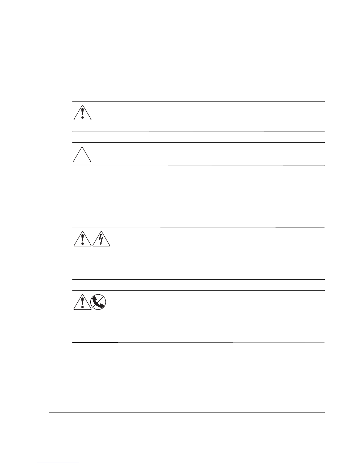
Symbols in Text
These symbols may be found in the text of this guide. They have the following
meanings.
WARNING: Text set off in this manner indicates that failure to follow directions
in the warning could result in bodily harm or loss of life or damage to
equipment.
CAUTION: Text set off in this manner indicates that failure to follow directions could
result in damage to equipment or loss of information.
IMPORTANT: Text set off in this manner presents clarifying information or specific instructions.
NOTE: Text set off in this manner presents commentary, sidelights, or interesting points of
information.
About this Guide
Symbols on Equipment
Any enclosed surface or area of the equipment marked with these
symbols indicates the presence of electrical shock hazards. Enclosed
area contains no operator serviceable parts.
WARNING: To reduce the risk of injury from electrical shock hazards, do
not open this enclosure.
Any RJ-45 receptacle marked with these symbols indicates a network
interface connection.
WARNING: To reduce the risk of electrical shock, fire, or damage to the
equipment, do not plug telephone or telecommunications connectors into
this receptacle.
MSL5000 Series Library User Guide xi
Page 12
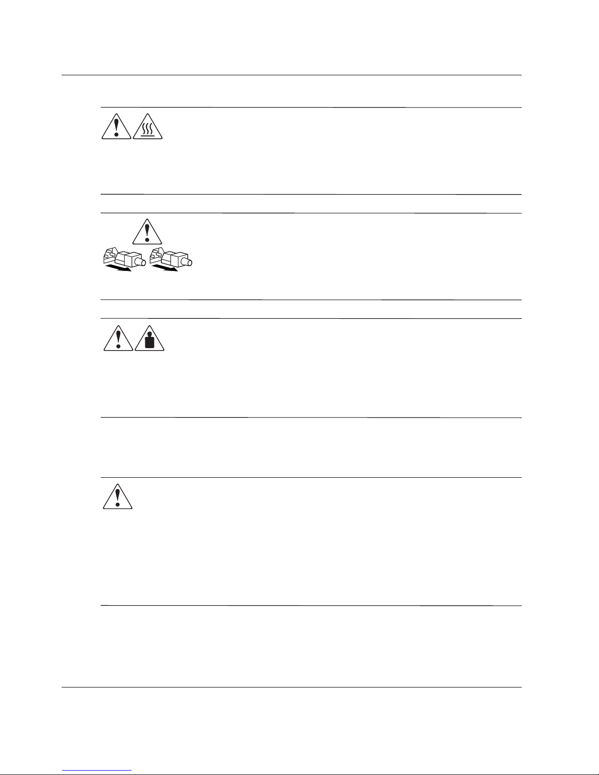
About this Guide
Any surface or area of the equipment marked with these symbols
indicates the presence of a hot surface or hot component. Contact with
this surface could result in injury.
WARNING: To reduce the risk of injury from a hot component, allow the
surface to cool before touching.
Power supplies or systems marked with these symbols indicate the
presence of multiple sources of power.
WARNING: To reduce the risk of injury from electrical shock,
remove all power cords to completely disconnect power from the
supplies and systems.
Any product or assembly marked with these symbols indicates that the
component exceeds the recommended weight for one individual to
handle safely.
Rack Stability
WARNING: To reduce the risk of personal injury or damage to the equipment, be
sure that:
• The leveling jacks are extended to the floor.
• The full weight of the rack rests on the leveling jacks.
• In single rack installations, the stabilizing feet are attached to the rack.
• Racks are coupled in multiple rack installations.
• Only one rack component is extended at any time. A rack may become
unstable if more than one rack component is extended for any reason.
WARNING: To reduce the risk of personal injury or damage to the
equipment, observe local occupational health and safety requirements
and guidelines for manually handling material.
xii MSL5000 Series Library User Guide
Page 13

Getting Help
If you still have a question after reading this guide, contact service representatives or
visit our website.
Technical Support
In North America, call the technical support at 1-800-OK-COMPAQ. This service is
available 24 hours a day, 7 days a week.
NOTE: For continuous quality improvement, calls may be recorded or monitored.
Outside North America, call technical support at the nearest location. Telephone
numbers for worldwide technical support are listed on the HP website:
http://thenew.hp.com/country/us/eng/support.html.
Be sure to have the following information available before you call:
• Technical support registration number (if applicable)
• Product serial numbers
About this Guide
• Product model names and numbers
• Applicable error messages
• Operating system type and revision level
• Detailed, specific questions
Product Website
The HP website has the latest information on this product as well as the latest drivers.
Access the HP website at:
Authorized Reseller
For the name of your nearest authorized reseller:
• In the United States, call 1-800-345-1518.
• In Canada, call 1-800-263-5868.
• Elsewhere, see the HP website for locations and telephone numbers.
http://www.compaq.com/storage/tape_index.html.
MSL5000 Series Library User Guide xiii
Page 14

Page 15

1
Introduction
The HP StorageWorks MSL5000 series library is a tape library system that combines
Digital Linear Tape (DLT), Super DLT (SDLT), and LTO (Linear Tape-Open) drive
technology with advanced robotics. Designed for backup operations with high-end
networks and high-performance servers, the library is the next generation performer in
high-volume backup and archival service. The library also features high availability,
maximum storage density, and easy serviceability.
The library SCSI interface-to-host system supports Low Voltage Differential (LVD).
The tape drives and robotics control functions each use separate SCSI connections and
SCSI ID addresses. Library SCSI I/O is provided through two VHDCI-series, 68-pin,
Micro-D SCSI connectors located at the rear of the unit directly under each tape drive.
Robotics SCSI I/O is provided through two VHDCI-series, 68-pin, Micro-D SCSI
connectors located on the library controller board.
The remainder of this chapter describes the major components of the library,
including:
• Models and accessories
• Tape drives
• Magazines
• Power supply
• Robotics
• Library controller board
• Accessory PCI slots
• Front panel indicators
• Multi-unit library configurations
MSL5000 Series Library User Guide 1–1
Page 16

Introduction
Models
The MSL5000 series library family includes the following models:
• MSL5026SL
• MSL5026DLX
• MSL5026S2
• MSL5030L1
• MSL5052SL
• MSL5052S2
• MSL5060L1
Any MSL5000 series library can operate as a standalone unit or can be installed in a
rack to form a larger integrated multi-unit library configuration. MSL5026/MSL5030
libraries contain up to two tape drives, two removable tape cartridge magazines, and
robotics capable of random or sequential tape cartridge operation.
MSL5052/MSL5060 libraries contain up to four tape drives, four removable tape
cartridge magazines, and robotics capable of random tape cartridge operation.
Accessories
Contact your authorized service provider or visit the HP website at
www.compaq.com/storage/tape_index.html
that are available for an MSL5000 series library.
IMPORTANT: Mixing media from different types of tape drives should only be done in
association with your application software media partitioning guidelines.
for the most current list of accessories
1–2 MSL5000 Series Library User Guide
Page 17
Tape Drives
MSL5000 series libraries support up to four tape drives (see Figure 1–1). SCSI I/O is
accomplished through two VHDCI-series, 68-pin, Micro-D SCSI connectors located
at the rear of the library directly beneath each tape drive.
Introduction
2
1
2
1
Figure 1–1: Library tape drive locations
1 Tape Drive 0
2 Tape Drive 1
3 Tape Drive 2
4 Tape Drive 3
4
3
MSL5000 Series Library User Guide 1–3
Page 18

Introduction
Magazines
MSL5000 series libraries contain two or four removable tape cartridge magazines that
are accessible through the front doors (see Figure 1–2).
1
2
1
1
2
2
Figure 1–2: Library magazines
1 Left Magazine(s), with integrated mail slot
2 Right Magazine(s)
Looking from the front of the library, each left tape magazine includes a mail slot,
which is accessible when that magazine door is open. Pivoting forward, this mail slot
feature lets you insert or remove a single tape without having to unlock, remove, and
reinventory the magazine. If a full tape cartridge magazine is required, the library can
be reconfigured to recognize each mail slot as a standard data slot. The right tape
magazine contains fixed cartridge slots (no mail slot feature), so it retains its full
capacity at all times.
1–4 MSL5000 Series Library User Guide
Page 19
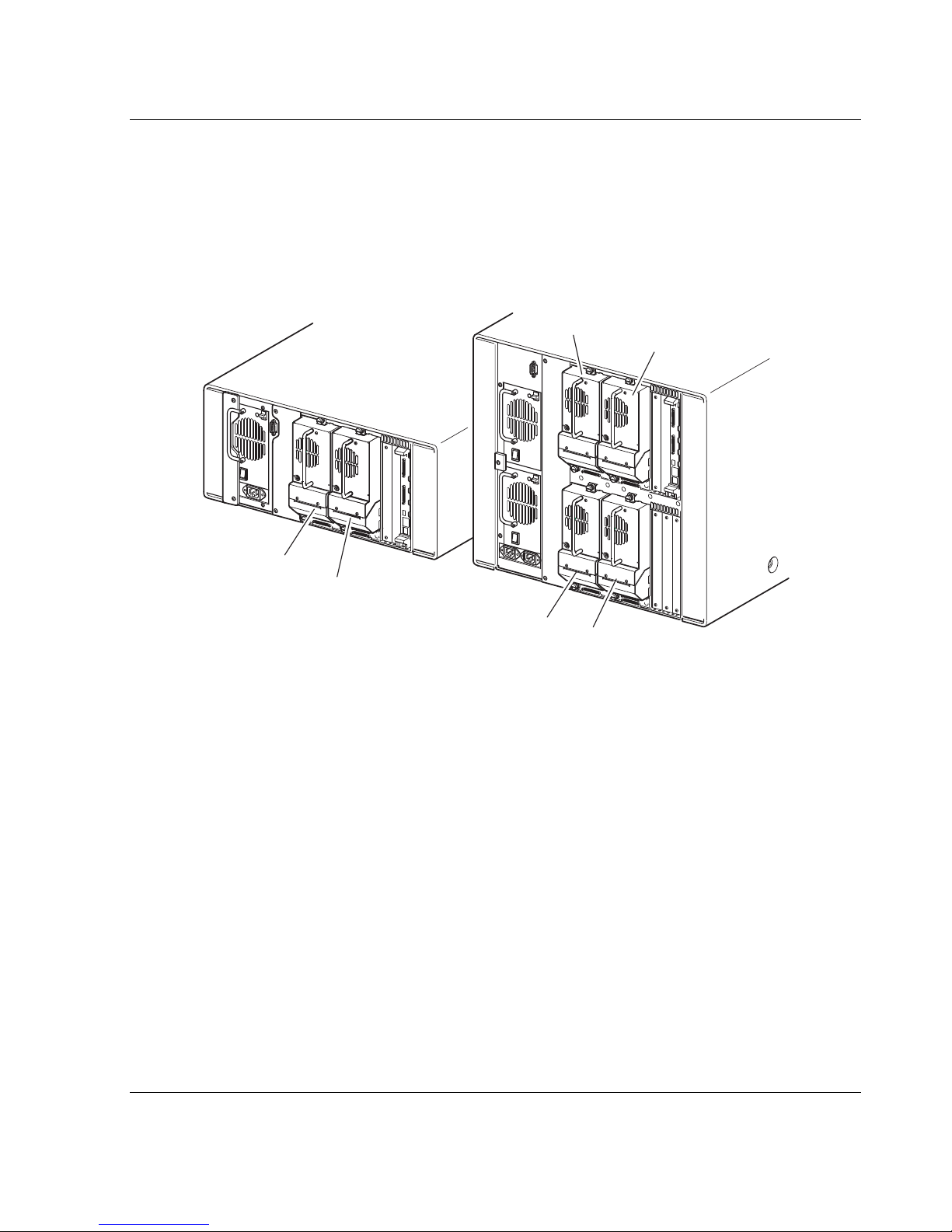
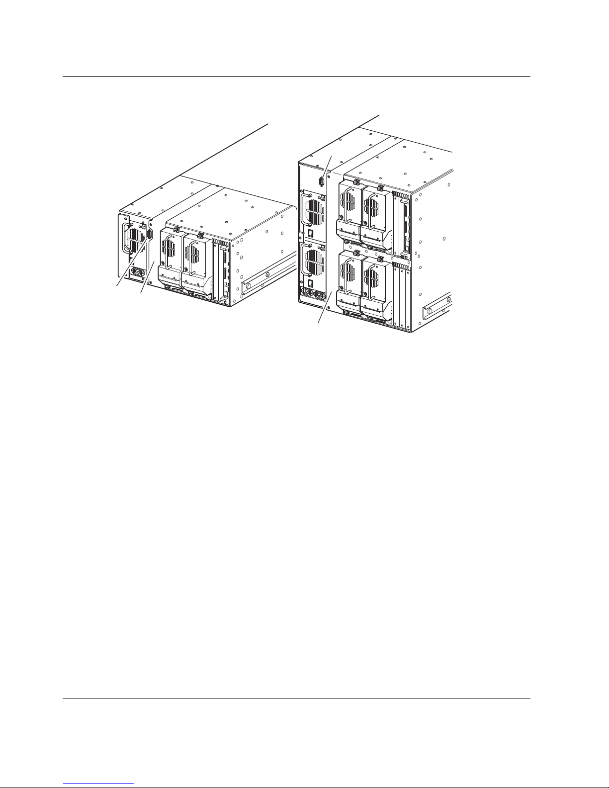
Power Supplies
MSL5000 series libraries support one or two power supplies that are accessible from
the rear of the unit (see Figure 1–3). These auto-ranging power supplies are capable of
using any nominal AC voltage between 100 VAC and 240 VAC power, at 50 Hz or 60
Hz, and are easily removed without requiring special tools.
Power to the library is supplied through AC connectors at the rear panel of each power
supply receiver. Library power is normally controlled from the Graphical User
Interface (GUI) touch screen; however, a manual power disconnect switch, located at
the rear of each power supply is provided.
CAUTION: The power supply is not to be removed by the operator. Hazardous voltage
is present in the cavity if the power cord is not removed.
Power supplies can be easily replaced in maintenance/service mode using a #1 Phillips
screwdriver to remove the power supply bracket.
For the MSL5052/MSL5060 libraries, two power supplies are supported to provide
redundancy for mission critical operations. Both power supplies share the load under
normal operating conditions, however, if one of the power supplies fail the remaining
power supply assumes the full load (see Figure 1-3 on the following page).
Introduction
MSL5000 Series Library User Guide 1–5
Page 20
Introduction
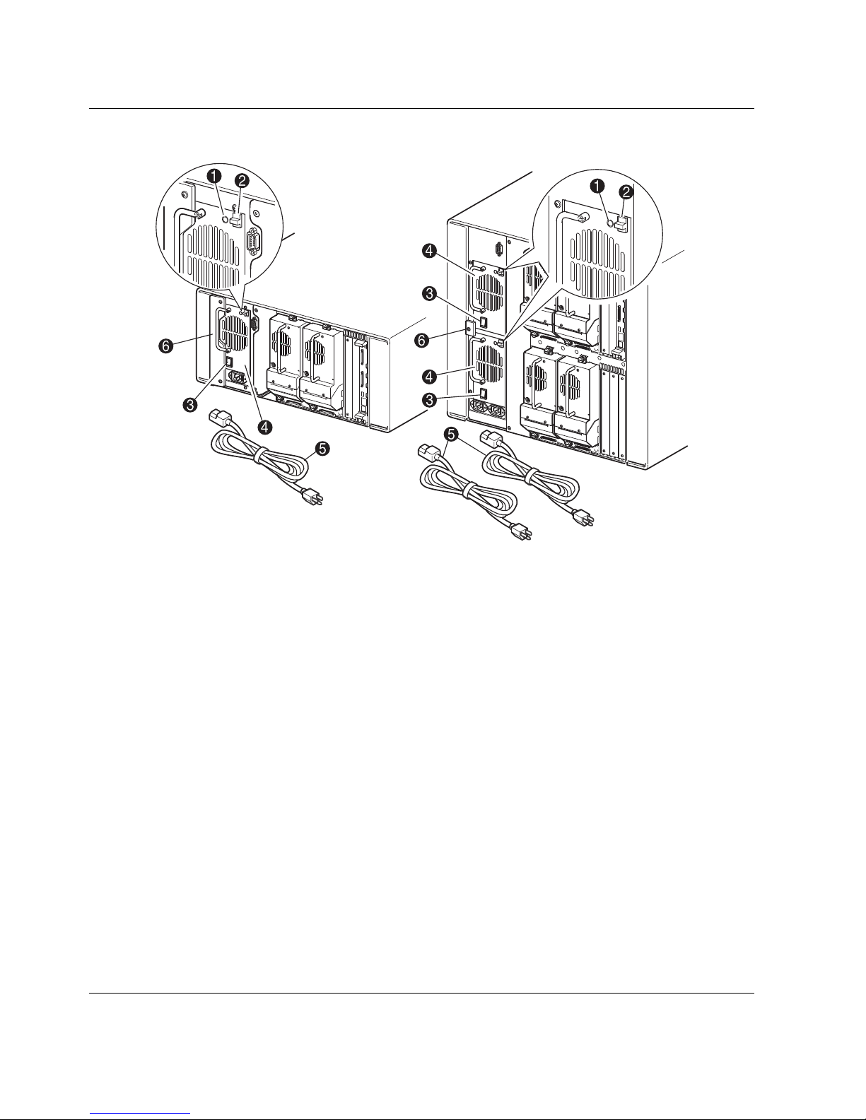
Figure 1–3: Library power supplies
NOTE: For the MSL5052/MSL5060, the left AC power receptacle is for the bottom power
supply. The right AC power receptacle is for the top power supply.
1 Power On LED (lights after touching the front panel display)
2 Power Supply Release Latch
3 Power Switch
4 Power Supply
5 AC Power Cord(s)
6 Power supply bracket
1–6 MSL5000 Series Library User Guide
Page 21
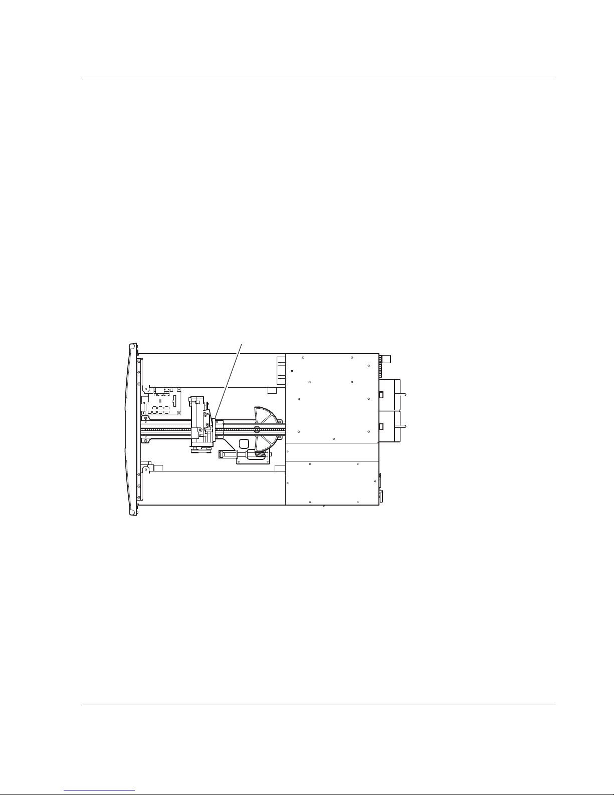
Robotics
MSL5000 series library robotics consist of a cartridge shuttle, motor hardware, motor
drives, and other support electronics (see Figure 1–4). The MSL5052MSL5060 library
also contains a vertical axis mechanism that enables the robotics to travel between the
upper and lower tape cartridge magazines. These robotics are capable of picking and
placing tapes throughout a 180-degree arc that consists of the tape drives, tape
cartridge magazines, and an optional Pass-Through Mechanism (PTM).
The cartridge shuttle assembly includes a mounted barcode reader for scanning tape
cartridges installed in the magazines and tape drives.
IMPORTANT: Both full barcode reader scan and physical scan are conducted each time the
library is initially powered up or each time a tape magazine is accessed using normal
operational modes.
In MSL5052MSL5060 libraries, the robotic-PTM interface is at the lower vertical axis
PTM elevator position only.
Introduction
1
Figure 1–4: Library robotics (top cover removed, MSL5026 shown)
1 Cartridge Shuttle Assembly with Integral Barcode Reader
MSL5000 Series Library User Guide 1–7
Page 22

Introduction
Library Controller Board
The library controller board contains a single microprocessor and associated logic
devices to control all robotics operations and manage overall library functions. The
microprocessor enables the SCSI interface between the library and the host system.
NOTE: The SCSI terminator must always be connected to the library controller board for proper
operation when configured as standalone or master.
The library controller board is installed in a card cage at the rear of the library and can
be serviced with using only a #1 Phillips screwdriver (see Figure 1–5).
IMPORTANT: For MSL5000 series libraries, the library controller board must be installed in the
right slot of the card cage area (upper card cage area for the MSL5052/MSL5060). The
remaining slots on the MSL5000 series libraries do not support the required connections for the
library controller board to operate correctly.
Figure 1–5: Library controller board
1 Library Controller Board
2 Factory-Defined Accessory PCI Slots (up to 5)
1–8 MSL5000 Series Library User Guide
Page 23
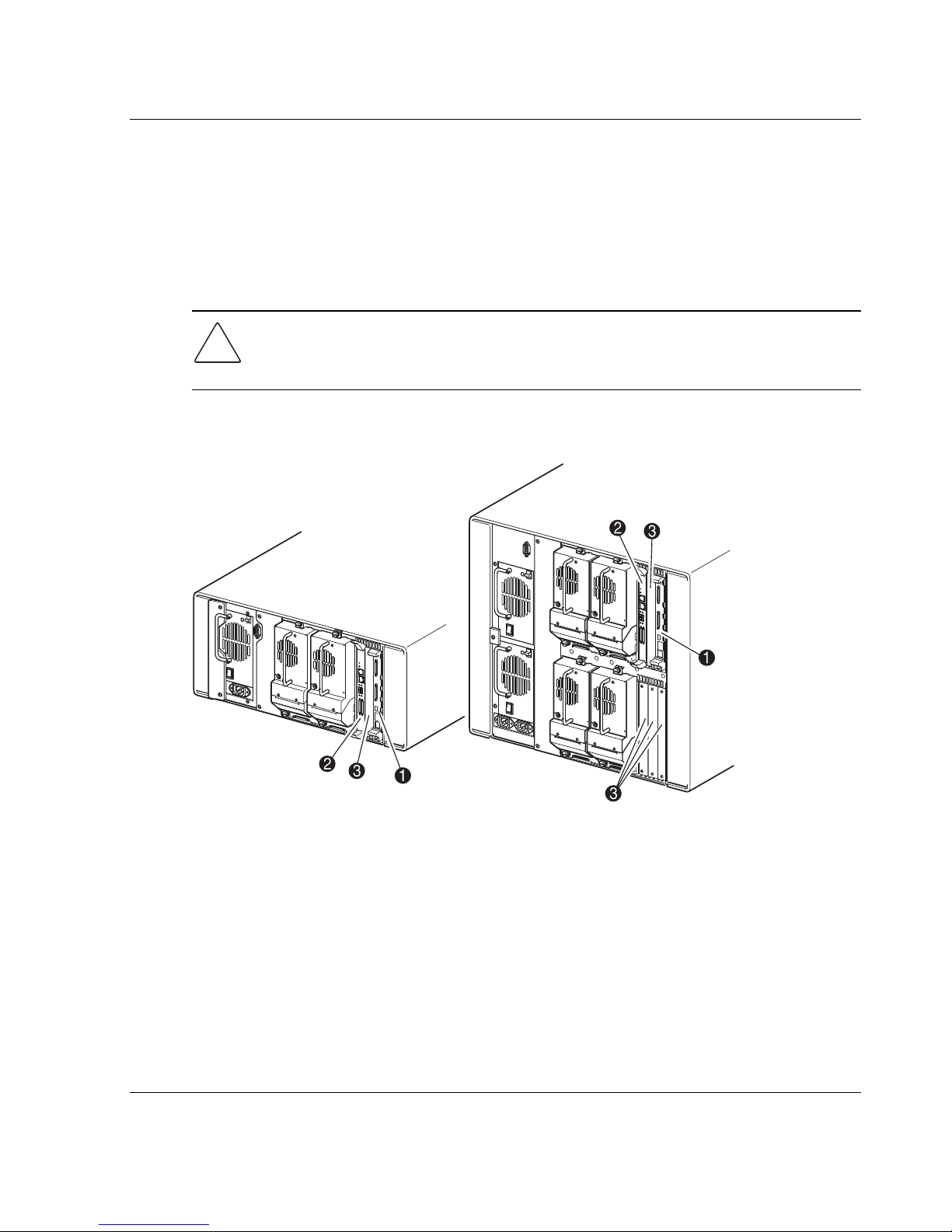
Factory-Defined Accessory PCI Slots
MSL5000 series libraries contain one or two rear-access card cages and one or two
32-bit, 33-MHz Compact PCI backplanes (see Figure 1–6). These backplanes contain
the plug-in connectors for a library controller board and up to five optional HP-defined
PCI add-in cards.
CAUTION: Use of non-HP qualified PCI option cards can damage your MSL5000
series library and will void product warranty. Follow all installation, configuration, and
operating instructions shipped with the option card upgrade kit.
IMPORTANT: For MSL5000 series libraries only, the library controller board must be installed
in the right slot of the card cage area (upper card cage area for the MSL5052/MSL5060).
Introduction
Pwr.
EthernetSerial
Act
Link/
Channel
Fibre
1
0
LVD/SE SCSl
Figure 1–6: Library card cages
1 Library Controller Board
2 Optional Embedded Fibre Channel Board
3 Factory-Defined Accessory PCI Slots (up to 5)
Pwr.
EthernetSerial
Act
Link/
Channel
Fibre
1
0
LVD/SE SCSl
MSL5000 Series Library User Guide 1–9
Page 24
Introduction
Embedded Fibre Channel Board
Some models of the MSL5000 series libraries ship with an optional embedded Fibre
Channel board in the slot next to the library controller board.
This board enables connectivity between MSL5000 series libraries and Fibre Channel
based storage area networks (SANs), allowing them to be attached to either a Fibre
Channel Arbitrated Loop (FC-AL) or switched fabric. See Appendix F for additional
information on configuring and using the optional Fibre Channel board.
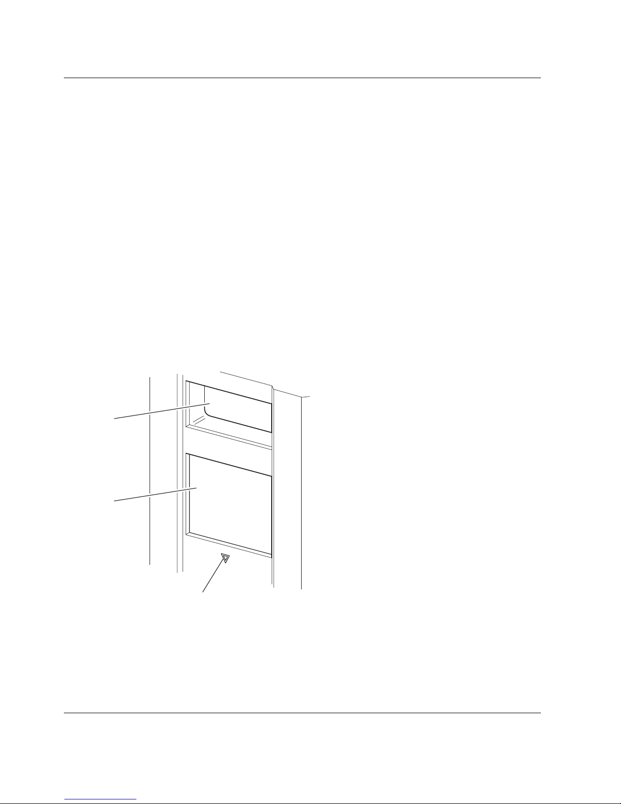
Front Panel Indicators
The library front panel indicators consist of the following:
• Viewing window—lets you visually check the internal operations of the library.
• GUI touch screen—manually operated to set up and configure the library.
• Library status LED—displays the library operational status of the library.
1
2
3
Figure 1–7: Library front panel
1 Viewing Window
2 GUI Touch Screen
3 Library Status LED
1–10 MSL5000 Series Library User Guide
Page 25
Multi-Unit Library Systems
MSL5000 series libraries can be stacked in a scalable combination with additional
MSL5026/MSL5030 and MSL5052/MSL5060 libraries to form a multi-unit library
configuration. Through use of a rear-mounted Pass-Through Mechanism (PTM), all
libraries in a multi-unit library configuration can operate together as a single virtual
library system. Stacked libraries are interconnected through their rear panel Ethernet
connections to a supplied LAN hub that mounts to the rack enclosure. The LAN hub
also provides a Wide Area Network (WAN) connector when libraries are combined in
their maximum stacked height.
A maximum of four MSL5052/MSL5060 or eight MSL5026/MSL5030 libraries can
be connected together in this manner. Any combination of eight libraries, not
exceeding 40 Units (40U) in total stacked height, can also be used. A multi-unit library
configuration appears to the host computer system and application software as a single
library. For multi-unit applications, the top library becomes the master unit and all
other libraries are slave units.
WARNING: The PTM continues to function each time a slave library is physically
removed from the rack enclosure configuration during normal library operation.
Refer to the
detailed installation, configuration, and operation information
hp StorageWorks Pass-Through Mechanism Reference Guide
Introduction
for
.
The library robotics can pick and place tape cartridges into a movable elevator that
encompasses the full length of the PTM. In this manner, individual tapes can be passed
up or down between the libraries contained in the multi-unit library configuration
under the master library control. Robotics access to the PTM is located at the rear of
the library beneath the PTM cover (see Figure 1–8 on the following page).
MSL5000 Series Library User Guide 1–11
Page 26
Introduction
Figure 1–8: Library PTM mounting location
1
1
2
2
1 PTM Interface Connector
2 PTM Mounting Cover (removal required for PTM installation)
1–12 MSL5000 Series Library User Guide
Page 27

Installation
This chapter explains how to install an HP StorageWorks MSL5000 series library.
Sections in this chapter include:
• Setting up the tabletop model
• Converting a tabletop model to a rackmount model
• Setting up the rackmount model
• Applying power to the library
• SCSI cable configurations
IMPORTANT: Be sure to keep and store all shipping materials from your MSL5000
series library.
2
MSL5000 Series Library User Guide 2–1
Page 28
Installation
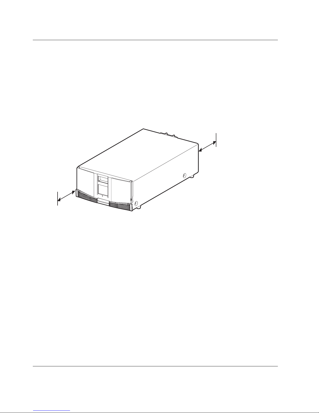
Setting up the Tabletop Model
Library tabletop models require no mechanical assembly for mounting (see
Figure 2–1). Place the library on a desk, table, or other stable, horizontal surface.
Make sure the cooling grills at the front and the fans at the rear of the library are not
obstructed. Allow 18 inches (50 cm) of clearance at the front and rear for magazine
and hot-plug tape drive access, without the need to reposition the library.
NOTE: To reduce tabletop clearance requirements, temporarily move the library forward or
rearward to access the hot-plug drive shoes and magazines, respectively.
18"
(50 cm)
18"
(50 cm)
Figure 2–1: Tabletop model clearances (MSL5026 shown)
2–2 MSL5000 Series Library User Guide
Page 29
Installation
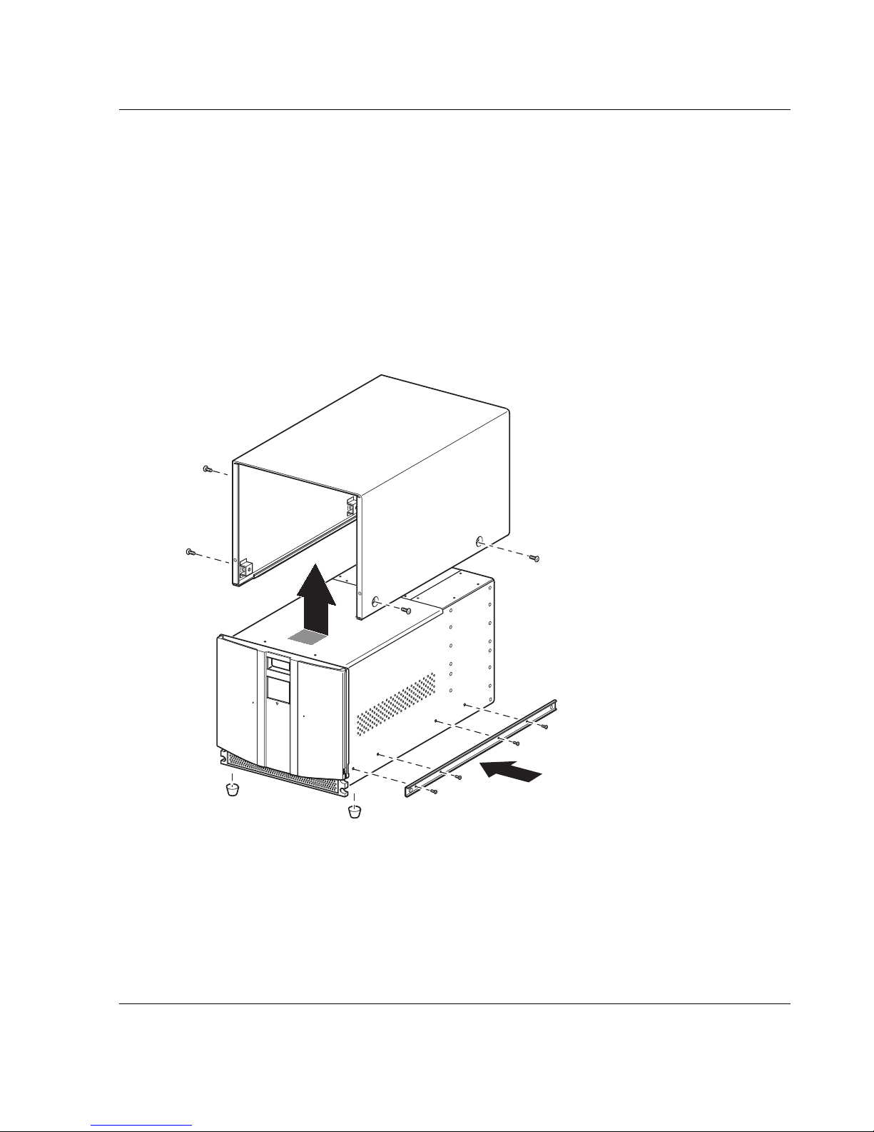
Converting a Tabletop Model to a Rackmount Model
To make a tabletop library ready for rack enclosure installation:
1. Remove the rubber feet.
Remove the cover.
Attach the inner rails to the library using the supplied allen wrench and screws.
Tighten the screws until snug.
Proceed to “Setting up the Rackmount Model.”
Figure 2–2: Converting a tabletop model
MSL5000 Series Library User Guide 2–3
Page 30
Installation
Setting up the Rackmount Model
Setting up the rackmount model requires a template, rack enclosure slide rails, and a
mechanical lift to physically install the library in a rack enclosure.
To setup the rackmount model:
1. Use the template that shipped with the library to mark the location of the
mounting hardware on the mounting rails of the rack enclosure (see Figure 2–2).
The black dots along the sides of the template indicate the top of a U.
MSL5052/
MSL5060
MSL5026/
MSL5030
Figure 2–3: Library template (9000 rack enclosure shown)
NOTE: For HP rack system/e and AlphaServer H9A rack enclosures, refer to the
appropriate rack rail adapter kit.
2. Remove the template and then attach the rails using the supplied fasteners (see
Figure 2–3). The front rail brackets are threaded to directly accept screws. The
rear brackets are not threaded and require cage/clip nuts in the rack enclosure rear
vertical rails.
NOTE: Refer to the
installation instructions on 7000/9000/10000 racks.
IMPORTANT: Fully tighten the front rail screws. Leave the rear rail screws “finger tight” to
prevent binding when mounting the library.
Compaq Rack Products Reference Guide
for detailed cage nut
2–4 MSL5000 Series Library User Guide
Page 31

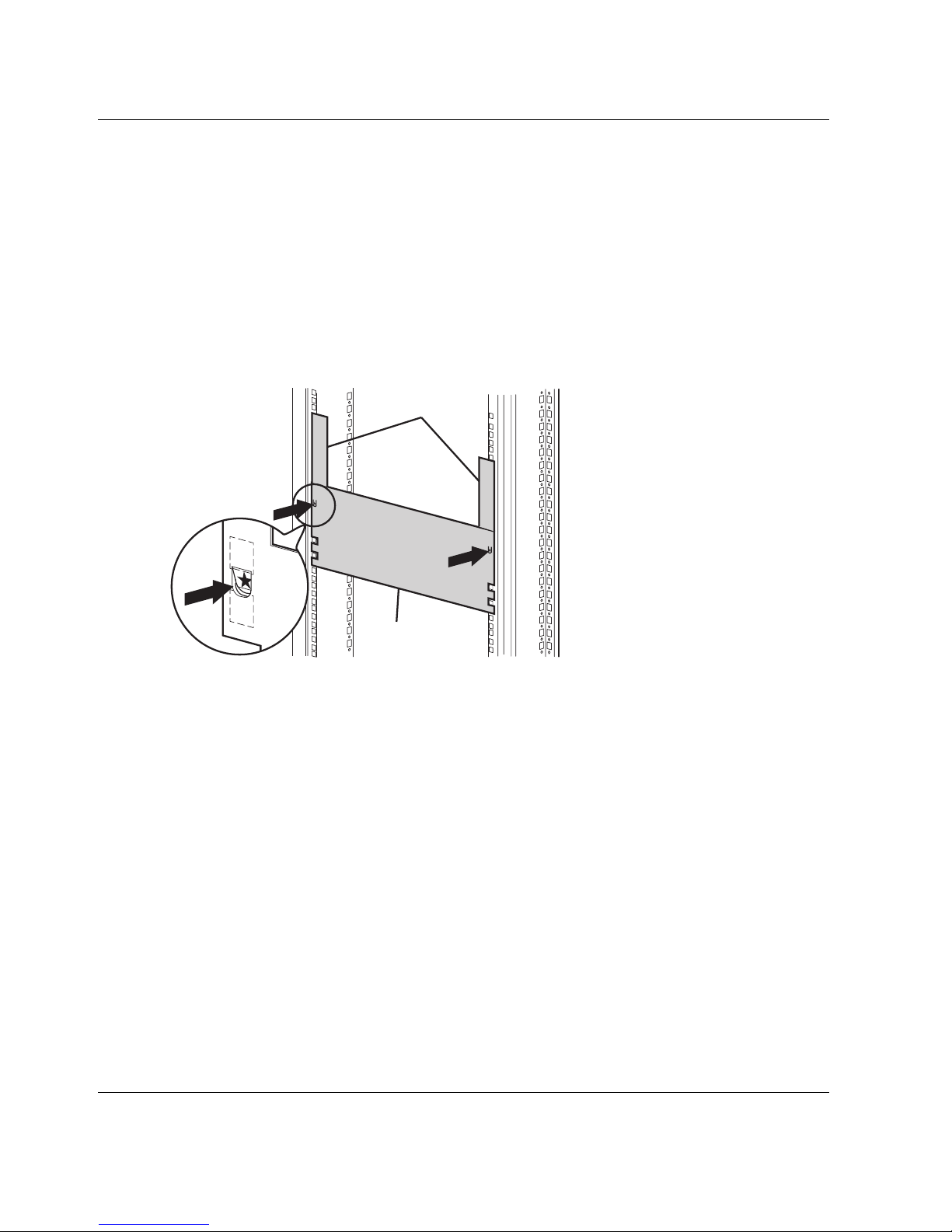
Installation
a. Fully extend the slide rails 1 on both sides of the rack enclosure until
they lock.
b. Slide the inner guide rail 2 as far as possible to the front of the rail assembly.
2
1
Figure 2–4: Installing the rails
MSL5000 Series Library User Guide 2–5
Page 32

Installation
3. Install the two slide-on clip nuts 1, (previously marked using the template, two
4. Using two people, lift the library and visually align the inner and intermediate
5. Carefully insert the library’s inner slide rails 3 into the extended intermediate
holes above the top bracket screw holes) on each of the front rack enclosure
vertical rails (Figure 2-4).
WARNING: Two people should perform the next step. Make certain, when the
library is fully extended, that a force of 20% of the rack enclosure’s weight, but
not more than 57 pounds (26 kg), applied in any direction other than upwards,
does not cause the rack enclosure to overbalance.
slide rails.
CAUTION: The library is heavier toward the tape drive end (rear).
slide rails 2 (see Figure 2–4).
6. Slide the library into the rack enclosure until the rail locks are engaged.
WARNING: A rack enclosure might become unstable if more than one
component is extended for any reason. Extend only one component at a time.
7. Push in on the rail locks to release the library and slide the library completely into
the rack enclosure.
8. Fully tighten the rear rail screws.
2–6 MSL5000 Series Library User Guide
Page 33

Figure 2–5: Installing the library (Model MSL5026 shown)
9. Remove the tape to open the doors for installation.
Installation
10. Remove and discard the pull-tabs used to block the latch mechanism.
IMPORTANT: Do not close the doors. You must have access to the two retaining screws to
complete the installation.
If necessary, see chapter 4, “Operation,” for information on how to manually open the
library doors.
11. With the doors open, secure the front panel to the rack enclosure using the two
retaining screws (see Figure 2–5). Close the doors.
You can now cable the library.
MSL5000 Series Library User Guide 2–7
Page 34

Installation
1
2
Figure 2–6: Securing the library
1 Left Retaining Screw
2 Right Retaining Screw
1
2
2–8 MSL5000 Series Library User Guide
Page 35

Applying Power to the Library
To apply power to the library (see Figure 2–6):
1. Connect each supplied power cord 1 to each power supply receptacle.
NOTE: The left AC power receptacle is for the bottom power supply. The right AC
receptacle is for the top power supply. (MSL5052/MSL5060 only).
2. Toggle each power switch 2 on.
3. Press anywhere on the Graphical User Interface (GUI) touch screen 3 to activate
the display and turn the library on.
IMPORTANT: The SCSI terminator must always be connected to the library controller
board for proper operation if configured as a master or standalone.
NOTE: Using a piece of tape to lift one corner, carefully remove the appliqué from the GUI
touch screen.
Installation
3
2
1
Figure 2–7: Applying power to the library (MSL5052 rackmount shown)
MSL5000 Series Library User Guide 2–9
Page 36

Installation
SCSI Cable Configurations
This section describes supported SCSI cable configurations for the library.
NOTE: MSL5000 series libraries support 1 to 4 host and 1 to 4 tape drive SCSI configurations.
Contact your authorized reseller for a list of supported configurations.
The following SCSI configurations are detailed in this section:
• Two tape drives dual host system (MSL5026/MSL5030).
• Four tape drives dual host system (MSL5052/MSL5060).
NOTE: Host cables are not supplied with any MSL5000 series library.
See Appendix E for additional configuration examples.
Supported SCSI Cables
NOTE: For optimum performance, a maximum of two tape drives per SCSI bus is
recommended.
Each of the tape drives in the library and the library controller constitute an
independent SCSI target. When any two or more devices are connected to the same
SCSI bus, each separate SCSI device must be assigned a unique SCSI ID. For
information on assigning SCSI IDs, see Chapter 3, “Library Configuration.”
NOTE: SCSI IDs are set at the factory. If you want to change any of the factory defaults, you
can do so using the GUI touch screen.
To connect a library to a host system, the host system must have at least one Wide
LVD controller and the appropriate driver software.
2–10 MSL5000 Series Library User Guide
Page 37

Two Tape Drives Dual Host System
Figure 2–7 shows a typical SCSI cable configuration for a library with two tape drives
installed using a dual host system.
5
4
Installation
1
2
3
Figure 2–8: MSL5026/MSL5030 SCSI cable configuration (two tape drives dual
host system)
1 SCSI Terminator
2 To Library Controller Board
3 To H o s t S ys t em
4 SCSI Terminator
5 To H o s t S ys t em
MSL5000 Series Library User Guide 2–11
Page 38

Installation
Four Tape Drives Dual Host System
Figure 2–8 shows a typical SCSI cable configuration for a library with four tape drives
installed using a dual host system.
5
1
2
1
4
5
3
4
Figure 2–9: MSL5052/MSL5060 SCSI cable configuration (four tape drives dual
host system)
IMPORTANT: The short 9.8-inch (0.25M) jumper cables 5 are designed for this use only.
Stretching either one to reach the library controller board can damage the cable. Use the longer
19.8-inch (0.5M) cable 2 to connect the tape drive and the library controller board.
1 SCSI Terminator 2 0.5M jumper cables
3 RS-232 diagnostic cable (for service only) 4 To H o s t S y st em
5 0.25M or 0.5M jumper cable
See Appendix E for additional configuration examples.
2–12 MSL5000 Series Library User Guide
Page 39

3
Library Configuration
This chapter explains how to configure an HP StorageWorks MSL5000 series library
for normal operation. Sections in this chapter include:
• Factory default configuration settings
• Setting a SCSI ID
• Setting up a reserved slot
• Setting up your network
MSL5000 Series Library User Guide 3–1
Page 40

Library Configuration
Default Configuration Settings
For most applications, you do not have to change the default settings; however, if you
do need to change a configuration setting, use the instructions provided in the
following sections. If you are uncertain whether you need to change a setting, contact
your HP authorized service provider.
Configuration settings that might need to be changed include:
• Setting a SCSI ID
• Setting up a reserved slot
• Setting up a network
Change configuration settings using the Graphical User Interface (GUI) touch screen.
For a complete description of how the GUI touch screen works, see Chapter 4,
“Operation.”
Setting a SCSI ID
Each tape drive installed in the library requires a unique SCSI ID. The information
provided in this section shows you how to set a SCSI ID.
To set a SCSI ID:
1. Turn the library on and wait until the Power-On Self Test (POST) completes and
the Status screen appears on the display.
2. Select the Menu option from the Status screen.
3. Enter the appropriate password. See the section on “Front Panel and Media
Security Locks” in Chapter 4 for instructions on how to set passwords.
3–2 MSL5000 Series Library User Guide
Page 41

Library Configuration
4. Select SCSI in the Edit Options area to display the following screen.
Figure 3–1: SCSI option selection screen (MSL5026 shown)
NOTE: You can move to the next sequential SCSI options screen by selecting the ▼. To return
to the previous SCSI options screen select the ▲ or Back button to return to the Menu screen.
5. For example, to set the Drive 0 Bus ID to 3:
a. Select the box next to the text “Drive 0 Bus ID:.” The Drive 0 Bus ID screen
appears on the display (see Figure 3–2). This screen displays the current Drive
0 Bus ID along with the new value that you request.
Figure 3–2: Drive 0 bus ID screen
MSL5000 Series Library User Guide 3–3
Page 42

Library Configuration
b. Touch the block that contains the number 3. This places your request into the
New data field.
c. Touch the Save option to confirm your request. A confirmation screen appears
on the display (see Figure 3–3).
Figure 3–3: SCSI ID confirmation screen
d. Touch OK to confirm. A new SCSI ID now appears in the Drive 0 Bus ID data
field (see Figure 3–4).
Figure 3–4: Drive 0 bus ID data field screen (MSL5026 shown)
6. Repeat this procedure to set any remaining SCSI IDs.
7. Touch the Back button repeatedly to return to the Main menu screen.
3–4 MSL5000 Series Library User Guide
Page 43

Setting Up a Reserved Slot
Use this option to designate one or more tape cartridge data storage slots as a cleaning
slot.
IMPORTANT: Reserved slots may be incompatible with some application software.
Reserved Slot Numbering
Standard tape cartridge slots are numbered from the front of the magazine to the rear
(see Figure 3–5 and Figure 3–7). If you reserve one slot, it becomes Reserved Slot #1
in the last slot of the last magazine. Additional reserved slots continue in this
rear-to-front pattern.
Library Configuration
1
#11
#10
#9
#8
#7
#6
#5
#4
#3
#2
#1
4
Figure 3–5: Reserved slot locations, DLT/SDLT (MSL5026)
1 Reserved Slot #1
2 Reserved Slot #2
3 Reserved Slot #3
4 Mail Slot (Left Magazine Only)
#0
#24
#23
#22
#21
#20
#19
#18
#17
#16
#15
#14
#13
#12
2
3
MSL5000 Series Library User Guide 3–5
Page 44

Library Configuration
4
#13
#12
#11
#10
#9
#8
#7
#6
#5
#4
#3
#2
#1
#0
#28
#27
#26
#25
#24
#23
#22
#21
#20
#19
#18
#17
#16
#15
#14
1
2
3
Figure 3–6: Reserved slot locations, LTO (MSL5030)
1 Reserved Slot #1
2 Reserved Slot #2
3 Reserved Slot #3
Mail Slot (Left Magazine Only)
3–6 MSL5000 Series Library User Guide
Page 45

1
Library Configuration
#36
#35
#34
#33
#32
#31
#30
#29
#28
#27
#26
4
Figure 3–7: Reserved slot locations, DLT/SDLT (MSL5052)
1 Reserved Slot #1
2 Reserved Slot #2
3 Reserved Slot #3
4 Mail Slot (Left Magazine Only)
#25
#49
#48
#47
#46
#45
#44
#43
#42
#41
#40
#39
#38
#37
2
3
MSL5000 Series Library User Guide 3–7
Page 46

Library Configuration
4
#42
#41
#40
#39
#38
#37
#36
#35
#34
#33
#32
#31
#30
#29
#57
#56
#55
#54
#53
#52
#51
#50
#49
#48
#47
#46
#45
#44
#43
1
2
3
Figure 3–8: Reserved slot locations, LTO (MSL5060)
1 Reserved Slot #1
2 Reserved Slot #2
3 Reserved Slot #3
Mail Slot (Left Magazine Only)
3–8 MSL5000 Series Library User Guide
Page 47

Library Configuration
To reserve a slot:
1. From the Menu screen, touch the Library option from the Edit Options area.
2. From the Library options screen, press the ▼ to scroll to the screen that contains
the Total Reserved Slots option (see Figure 3–9).
Figure 3–9: Total reserved slots screen
3. Press the associated box next to the Total Reserved Slots option. A numeric
keypad appears on the display (see Figure 3–10).
Figure 3–10: Reserved slots numeric keypad screen
MSL5000 Series Library User Guide 3–9
Page 48

Library Configuration
4. Enter the number of slots to reserve and then press Save to confirm your change.
A confirmation screen appears on the display (see Figure 3–11). Press OK to
save.
Figure 3–11: Total reserved slots confirmation screen
5. Press the Back button repeatedly to return to the Main menu screen. Your choice
takes effect the next time you boot the library.
3–10 MSL5000 Series Library User Guide
Page 49

Setting Up Your Network
The library automatically obtains an IP address from a DHCP server when the library
is powered up. The library also supports user-specified fixed addresses through the
front panel. To set a fixed address:
1. From the Menu screen, touch Network from the Edit Options area. The IP
Address Determination screen appears (see Figure 3–12).
Library Configuration
Figure 3–12: IP address determination screen
2. Touch the IP Address Determination option (see Figure 3–12) and then the User
Specified IP Address option (see Figure 3–13).
Figure 3–13: User-specified IP address screen
3. Touch OK to confirm your selection.
MSL5000 Series Library User Guide 3–11
Page 50

Library Configuration
4. Touch each IP address option and then use the keypad to enter each IP address
(see Figure 3–14).
5. Save and confirm your selections.
Figure 3–14: Fixed IP address screen
6. Press the Back button repeatedly to return to the Main menu screen.
3–12 MSL5000 Series Library User Guide
Page 51

4
Operation
This chapter describes how to operate an HP StorageWorks MSL5000 series library.
Sections in this chapter include the following:
• Front panel
• Inserting and removing tape cartridges
• Library display screens and options
MSL5000 Series Library User Guide 4–1
Page 52

Operation
Front Panel
The front panel of the library includes the left and right magazine doors, a Graphical
User Interface (GUI) touch screen, a library status LED, and a viewing window (see
Figure 4–1).
1
2
3
4
5
1
2
3
4
5
Figure 4–1: Library front panel
1 Left Magazine Door
2 Viewing Window
3 GUI Touch Screen
4 Library Status LED
5 Right Magazine Door
4–2 MSL5000 Series Library User Guide
Page 53

Magazine Doors
The magazine doors have both an electrical release (via the GUI touch screen) and a
manual release. It is always recommended that you open the magazine doors using the
GUI touch screen. However, should the GUI touch screen fail, you can manually open
them by pushing a small metal pin or paper clip into the mechanical releases (see
Figure 4–2).
CAUTION: The magazine doors must only be opened manually in an emergency.
Failure to follow normal procedures can cause data loss and equipment damage.
NOTE: The library may not perform a complete inventory each time a magazine is manually
removed and then replaced using the emergency release.
Operation
1
Figure 4–2: Magazine door mechanical releases (emergency access)
1 Left Magazine Door Release
2 Library Status LED
3 Right Magazine Door Release
MSL5000 Series Library User Guide 4–3
2
3
31 2
Page 54

Operation
Indicators
The library front panel indicators consist of a GUI touch screen and a library status
LED (see Figure 4–3 and Table 4–1).
1
2
Figure 4–3: Library indicators
1 GUI Touch Screen
2 Library Status LED
Table 4–1: Library Status LED
Indicator Description
Solid green The library is operating correctly under normal
conditions.
Flashing green The library is operating correctly; however, a change is
being made on the GUI touch screen that interrupts the
current library operation (off-line).
Solid amber The library is in a fault state as detailed by the error
message on the GUI touch screen.
4–4 MSL5000 Series Library User Guide
Page 55

Front Panel and Media Security Locks
The following security features are available to help you avoid accidental interruption
of library operation.
GUI Touch Screen
The GUI touch screen offers three levels of security (see Figure 4–4):
• User Level 1—allows access to the mail slot(s).
• User Level 2—allows magazine access, mail slot access, SCSI options,
diagnostics, and lets you move media.
• Service—allows access to the menu that lets you view/edit library and SCSI
options.
NOTE: The library ships with a default service password of 5566.
Operation
Figure 4–4: Password levels
Each password is represented by four decimal digits that are stored in NVRAM in a
range of 0001 to 9999.
NOTE: 0000 is used to disable password verification for each level.
Enabling a password at a lower level re-enables disabled higher levels to that value. As
a result, prior to accessing any higher level operation, you are prompted first to enter
the new higher level password.
MSL5000 Series Library User Guide 4–5
Page 56

Operation
You can also use a higher level password to gain access to a lower level operation. For
example, use the Service password to access the Move Media operation. Using the
Service password to access the Menu option also gives full access (without validating)
to the Service operations.
NOTE: To restore passwords if forgotten, use Set User Defaults using the MSL5000 Utility and
diagnostic cable. Note that any configuration that was previously set will be lost.
Host System
Media can also be locked by software running on the host. The library provides no
GUI touch screen override for this command. Usually, exiting the host software
restores media access. In the event of host failure, you can restore media access by
cycling the library power. Procedures for locking and unlocking magazine doors and
media are described later in this chapter.
Inserting and Removing Tape Cartridges
Unless you are using the mail slot(s), a tape magazine must be removed from the
library to remove or insert tape cartridges. Make sure the slot you want to use is not
already reserved for a tape cartridge that is now in a tape drive. The safest way to do
this is to unload all tape drives before removing a magazine. You can unload all the
tape drives either through your host system software or by using the LOAD/UNLOAD
command from the Library Option menu.
IMPORTANT: Do not add more tape cartridges to the library than its rated slot capacity.
4–6 MSL5000 Series Library User Guide
Page 57

Removing Magazines
Library magazine removal is a manual operation. Access the magazines using the
Magazine Access option from the library Status screen. For the MSL5026/SML5030,
this option lets you open the left or right magazine doors separately or both magazine
doors at the same time. For the MSL5052/MSL5060, this option lets you open the
upper-left, lower-left, or right magazines separately or both magazine doors at the
same time. After opening the appropriate magazine door, pull the magazine out from
the library chassis (see Figure 4–5).
1
Operation
2
1
1
Figure 4–5: Removing tape cartridge magazines
1 Left Magazine(s)
2 Right Magazine(s)
2
2
MSL5000 Series Library User Guide 4–7
Page 58

Operation
Inserting Cartridges into a Magazine
A full left magazine is shown in Figure 4–6. For the MSL5026/SML5030, the lowest
numbered tape cartridge slot 2 is the one closest to the front of the magazine. For the
MSL5052/MSL5060, the lowest numbered tape cartridge slot 2 is the one closest to
the front of the upper-left magazine.
1
3
2
Figure 4–6: Left tape magazine with tape cartridges installed (SDLT shown)
1 Tape Cartridge Orientation for Left Magazine
2 Lowest Numbered Tape Cartridge Slot
3 Highest Numbered Tape Cartridge Slot
4–8 MSL5000 Series Library User Guide
Page 59

Operation
Insert tape cartridges so that the bar code labels are facing outward (see Figure 4–7).
NOTE: Handle and store tape cartridges in a clean, dust-free environment.
-
Figure 4–7: Inserting a tape cartridge (left magazine, SDLT shown)
MSL5000 Series Library User Guide 4–9
Page 60

Operation
Using Mail Slots (Left Magazines Only)
Mail slots are used only with host system software that supports this feature. The mail
slot feature lets you insert or remove a single tape without removing the entire
magazine. Access the mail slots using the Mail Slot Access option from the library
Status screen. This option lets you open a left magazine door for mail slot access.
After opening a left magazine door, pivot the mail slot forward to insert a tape
cartridge (see Figure 4–8).
IMPORTANT: Mail slots must be enabled (factory default) using the Mail Slot Mode option from
the Edit Library Options menu. See Table 4-2 for more information.
NOTE: Disabling a mail slot allows it to be used for an additional data slot, but this may be
incompatible with some applications.
1
2
Figure 4–8: Left magazine mail slot (MSL5026 shown)
1 Mail Slot Holder
2 Tape Cartridge
4–10 MSL5000 Series Library User Guide
Page 61

Barcode Labels
Only HP or Compaq barcode labels are supported with the library. To order additional
labels, contact your authorized reseller.
Figure 4–9 shows you how to attach a barcode label onto an SDLT or DLT tape
cartridge.
Operation
Figure 4–9: Attaching a barcode label to an SDLT tape cartridge
MSL5000 Series Library User Guide 4–11
Page 62

Operation
Figure 4-10 shows you how to attach a barcode label onto an LTO Ultrium 1 cartridge.
Figure 4–10: Attaching a barcode label to an LTO Ultrium 1 tape cartridge
Figure 4–11: Proper LTO Ultrium 1 barcode label placement
4–12 MSL5000 Series Library User Guide
Page 63

Library Display Screens and Options
The library GUI touch screen displays graphics and text characters in the form of
easy-to-understand messages. Graphics and text messages, along with their functions,
are described in this section.
Initialization Screen
When power is first applied to the library, a series of Power-On Self Test (POST)
diagnostics are performed. After the POST completes, the following initialization
screen appears while library inventory and scalability configuration occurs:
Operation
Figure 4–12: Initialization screen
MSL5000 Series Library User Guide 4–13
Page 64

Operation
Library Status Screen
After the POST executes successfully and the library initialization completes
(approximately 45 seconds), the following library Status screen appears:
12
Figure 4–13: Library status screen (MSL5026 shown)
1 Technical Support Information Option
2 LCD Contrast Controls (volatile settings)
The library Status screen lets you select the following options:
• Technical Support Information Option
• Mail Slot Access
• Magazine Access
• Move Media
• LCD Contrast Controls
•Power
• Status Information
• Online/Offline
• Menu Access
The remainder of this section describes each of the options that are available from the
library Status screen.
4–14 MSL5000 Series Library User Guide
Page 65

Technical Support Information Option
Selecting this option lets you display HP-specific technical support assistance
information (see Figure 4–14). If you are having difficulty with a direct connection,
instructions on how to contact your local service provider is included, along with a
toll-free number to contact HP directly. For further assistance, you can also access the
HP website at http://thenew.hp.com/country/us/eng/support.html.
Operation
Figure 4–14: Technical support information screen
Mail Slot Access Option (Left Magazines Only)
Select this option to display the Mail Slot Access screen (Figure 4–15). This option
lets you gain access to a mail slot without powering down the library. Note that a mail
slot is reserved for the first tape cartridge slot in a left magazine and can be password
protected or fully disabled. If disabled, this menu button is absent. On
MSL5052/MSL5060 libraries, solenoids restrict access to the selected mail slots.
MSL5000 Series Library User Guide 4–15
Page 66

Operation
Figure 4–15: Mail slot access screen (MSL5052 shown)
Magazine Access Option
Select this option to display the Magazine Access screen (Figure 4–16). For the
MSL5026/MSL5030, this option lets you gain access to the left or right magazine
doors separately or both magazine doors for tape cartridge placement or removal. For
the MSL5052/MSL5060, this option lets you gain access to the upper-left, lower-left,
or right magazines separately or both magazine doors for tape cartridge placement or
removal. Note that this option can also be password protected.
Figure 4–16: Magazine access screen (MSL5026 shown)
Move Media
Select this option to display the Move Media screen (see Figure 4–17). The Move
Media option lets you remove a cartridge from a tape drive, a data slot in any
magazine, or a mail slot in a left magazine. This option also lets you load and unload
tape cartridges from the installed tape drives.
4–16 MSL5000 Series Library User Guide
Page 67

Operation
See the section on “Replacing a Cleaning Cartridge in a Reserved Slot” in Chapter 6
for detailed removal information.
CAUTION: DLT, SDLT, and LTO Ultrium 1 cleaning cartridges must only be used in
their respective drive types or drive damage can result.
CAUTION: Remove media from all drives and slots prior to library transport.
Figure 4–17: Move media screen
LCD Contrast Controls
Select these options to increase or decrease the contrast of the LCD display (see
Figure 4-13). Incremental steps are set by adjusting the LCD contrast controls from
the library Status screen. Incremental steps can range from 0 to 31 depending on your
preference. These settings are volatile and are restored to default values upon reboot or
power cycling.
Power
Select this option to initiate a library power-down operation. After a successful power
down, a confirmation message appears (see Figure 4–18).
IMPORTANT: The library moves the shuttle assembly to the parked position before powering
down. This is necessary for any library transport.
MSL5000 Series Library User Guide 4–17
Page 68

Operation
Status
Figure 4–18: Power-down confirmation message screen
Select this option to display an information Status screen (Figure 4–19). From this
screen, touch a magazine icon to display detailed information about the cartridges in
that magazine. Touch a drive icon to view drive ID information, cleaning status,
cartridge information, and drive status.
Figure 4–19: Status screen (MSL5052 shown)
Online
Selecting this option lets you place the library online or offline.
NOTE: The library automatically comes online after a power-up initialization. You can use this
option to place the library offline.
4–18 MSL5000 Series Library User Guide
Page 69

Menu
Operation
Selecting this option lets you view, configure, and use the library (Figure 4–20). The
Menu option displays three distinct areas:
• View System Data
• Utilities
• Edit Options
For a complete description of these areas, see the section on “Menu Selections”
described later in this chapter.
Figure 4–20: Menu screen
MSL5000 Series Library User Guide 4–19
Page 70

Operation
Menu Selections
This section describes the three Menu areas:
• View System Data
• Edit Options
• Utilities
View System Data Area
The View System Data area lets you select the following screens:
• Library Options
• SCSI Options
• Network Options
• Library Info
• Cartridge Map
Library Options
Selecting this option lets you view the settings defined from the Library option in the
Edit Options area (see Figure 4–21).
NOTE: You can move to the next subsequent Library Options screen by selecting the ▼. To
return to the previous Library Options screen select the ▲ or Back button to return to the Menu
screen.
Figure 4–21: View library options screen
4–20 MSL5000 Series Library User Guide
Page 71

Table 4–2 lists and describes the available Library options.
Table 4–2: View Library Options
Option Description
Operation
Library Remains Offline After
Power-up Initialization
Library does not go online after power-up initialization. You
must select the Online option from the Menu screen on the
GUI touch screen. The default is Disabled.
Auto Power-Up
An Installed Drive After
Timeout
Enables a tape drive to be automatically powered up (after a
delay), after replacing a tape drive if you do not explicitly
power up the tape drive from the GUI touch screen. The
default is Enabled.
Unload Mode Lets you determine whether a SCSI MOVE MEDIUM
command is interpreted as Implicit or Explicit. If Implicit, the
library unloads a tape drive before attempting to move a
cartridge from that tape drive. If Explicit, the host must issue a
SCSI UNLOAD command to a tape drive before each MOVE
MEDIUM command that removes a cartridge from that tape
drive. The default is Implicit.
Total Reserved Slots Lets you remove from use a specified number of slots at the
rear of a magazine. Some host software imposes size limits
on library magazines for licensing purposes, and does not
operate with a library that exceeds the licensed size. The
default is 0.
Auto Clean Mode Lets you enable an automatic tape drive cleaning cycle. To
use this option, you must have reserved a slot for a cleaning
cartridge using the Total Reserved Slots option. The default is
Disabled.
Drive and Slot Numbering Lets you specify whether SCSI elements in the library
Library Mode Lets you set the robotics operating mode to Random,
MSL5000 Series Library User Guide 4–21
displays with either zero based or one based. Note that this
only affects the GUI touch screen, not the actual SCSI
element addresses. The default is Zero Based.
Sequential Drv0, Sequential Drv1, and Sequential Split for
the MSL5026/MSL5030. The MSL5052/MSL5060 is not
supported in sequential modes. The default is Random
(Sequential Mode Unavailable).
Page 72

Operation
Table 4–2: View Library Options (Continued)
Option Description
Sequential Mode Selecting a sequential mode (using Library Mode) enables
the library robotics to unload a full tape cartridge (or at the
end of data), select, load the next tape cartridge from the
appropriate magazine, and then automatically continue
read/write operations without software intervention. Two
options are available: Normal and Recirculate.
LCD Contrast Adjust The LCD contrast controls let you increase or decrease the
contrast of the LCD display. The incremental steps are set by
adjusting the LCD Contrast Adjust option from the Library
option. Incremental steps can range from 0 to 31 depending
on your preference. The default is 16.
Mail Slot Mode Lets you enable or disable the mail slot(s) in a library. For the
MSL5026/MSL5030, the default is Mail Slot Enabled. For the
MSL5052/MSL5060, the default is Both Mail Slots Enabled.
Barcode Label Size Lets you limit the length of the barcode label. Possible
settings are 1 through 8. The default is 8.
Barcode Label Assignment Lets you specify the alignment of a bar code label. The
options are Left or Right. When used in conjunction with the
label size option, this option strips unwanted trailing
characters (left alignment) or leading characters (right
alignment). The default is Left Align.
Barcode Label Check Digit Lets you specify whether to enable or disable the verification
of a check digit character in the barcode label. The default is
Disabled.
Barcode Reader Lets you enable or disable the barcode reader retries option.
The default is Retries Enabled.
Module Configuration Lets you configure a library for standalone, master, or slave
operation. The default is Standalone.
4–22 MSL5000 Series Library User Guide
Page 73

SCSI Options
Selecting this option lets you view the settings defined from the SCSI option in the
Edit Options area (see Figure 4–22).
NOTE: You can move to the next sequential SCSI Options screen by selecting the ▼. To return
to the previous SCSI Options screen, select the ▲ or Back button to return to the Menu screen.
Operation
Figure 4–22: View SCSI options screen
Table 4–3 lists and describes the available selections.
Table 4–3: View SCSI Options
Option Description
Drive 0 Bus ID Lets you set the SCSI addresses of drive 0. The
designators Drive 0 (outer tape drive) through Drive
refer to the first through
left starting with the master unit in the scaled Library
system.
Drive 1 Bus ID Lets you set the SCSI addresses of drive 1. The
designators Drive 1 (inner tape drive) through Drive
refer to the second through
right to left starting with the master unit in the scaled
Library system.
Drive 2 Bus ID
(MSL5052/MSL5060
only)
Lets you set the SCSI addresses of drive 2. The
designators Drive 2 (lower, outer tape drive) through
Drive
n
refer to the third through nth drives, counting
from right to left starting with the master unit in the
scaled Library system.
n
th drives, counting from right to
n
th drives, counting from
n
n
MSL5000 Series Library User Guide 4–23
Page 74

Operation
Table 4–3: View SCSI Options (Continued)
Option Description
Drive 3 Bus ID
(MSL5052/MSL5060
only)
Lets you set the SCSI addresses of drive 3. The
designators Drive 3 (lower, inner tape drive) through
Drive
n
refer to the fourth through nth drives, counting
from right to left starting with the master unit in the
scaled Library system.
Library SCSI Bus ID Lets you set the SCSI addresses for the library robotics.
The default is 0.
Library SCSI Bus
Parity
Lets you enable or disable the library robotics SCSI bus
parity checking. The default is Library SCSI Bus Parity
Enabled.
Mail Slot Access “Prevent Allow” Command Inhibits or “Prevent Allow”
Command Ignored (used for some backup
applications). “Prevent Allow” Command Inhibits is the
default.
SCSI Mode Defines the loader as SCSI-2 or SCSI-3. The default is
SCSI-3.
Unit Attention
Reporting
Lets you select reporting of All or only One stacked-unit
attention conditions. If set to All, the unit reports all unit
attention conditions in sequence; if set to One, the unit
reports only the highest priority condition. The default is
Report All.
Init Element Status Lets you specify the library’s response to the SCSI
INITIALIZE ELEMENT STATUS command. The
possible settings are No Inventory, Force Inventory, and
Force Label Scan. The default is Force Inventory.
Test Unit Ready
Reporting
Lets you specify the response to a TEST UNIT READY
command if the library is in Sequential Mode. The
possible settings are Standard or Custom. The default is
Custom.
Device Capability Page
Length
Lets you choose between two lengths of the mode
sense/select device capabilities page (SCSI page 1Fh),
which are short (14 bytes) and long (18 bytes), to
accommodate different SCSI device implementations of
this page. The default is Short (14 bytes).
Transport Element
Base Address
4–24 MSL5000 Series Library User Guide
Lets you set the base address for the robotics
mechanism. The default is 0x0.
Page 75

Table 4–3: View SCSI Options (Continued)
Option Description
Operation
Storage Element
Base Address
Transfer Element
Base Address
Import/Export Element
Base Address
Lets you set the base address for the magazine slots.
The default is 0x20.
Lets you set the base address for the tape drives. The
default is 0x1e0.
Lets you set the base address for the mail slot. The
default is 0x1c0.
Product Identification Lets you specify the response of the library’s robotics to
the SCSI INQUIRY command in the Product ID fields.
The default is “MSL5000 Series.”
Vendor Identification Lets you specify the response of the library’s robotics to
the SCSI INQUIRY command in the Vendor ID field. The
default is “Compaq.”
Post Recovered Errors The default is Disabled.
TapeAlert Mode Specifies conditions for logging and reporting the
following Tape Alert data options. The default is Logging
Disabled.
Logging Disabled: Inhibits the logging feature.
No Exceptions: The library must not report information
exceptions.
Generate Unit Attention: Reports information
exceptions with a Unit Attention sense key and an
ASC/ASCQ of 5D/00.
Conditionally Generate Recovered Error: Reports
information exceptions with a Recovered Error sense
key and an ASC/ASCQ of 5D/00, if Recovered Error
Reporting is enabled.
Unconditionally Generate Recovered Error:
Unconditionally reports information exceptions with a
Recovered Error sense key and an ASC/ASCQ of
5D/00.
Generate No Sense: Reports information exceptions
with a No Sense sense key and an ASC/ASCQ of
5D/00.
MSL5000 Series Library User Guide 4–25
Page 76

Operation
Table 4–3: View SCSI Options (Continued)
Option Description
Report on Unsolicited Request Sense: Reports
information exceptions with a No Sense sense key and
an ASC/ASCQ of 5D/00, only in response to an
unsolicited REQUEST SENSE command.
Abort Move Status Lets you specify the SCSI response while aborting a
SCSI command. The possible settings are Busy or Not
Ready. The default is Not Ready.
Door Open Response Lets you specify the SCSI response when a library door
is open. The settings are Ready or Not Ready. The
default is Not Ready.
Initiate Wide Data
Transfer Negotiation
Lets you enable the library to initiate a SCSI
synchronous and wide data transfer negotiation with the
host. The settings are Do Not Initiate or Initiate. The
default is Do Not Initiate.
Data Transfer Speed Lets you set the robot or library SCSI data transfer rate
to Synchronous, 10 MB/s, 5 MB/s, or Asynchronous
Only. The default is Synchronous, 10 MB/s.
4–26 MSL5000 Series Library User Guide
Page 77

Network Options
Selecting this option lets you view the settings defined from the Network option in the
Edit Options area (see Figure 4–23). Table 4–4 lists and describes the available
options.
NOTE: There are no factory default settings for networks. Contact your network administrator
for specific information on connecting the library to your network.
Operation
Figure 4–23: Default view network options screen
NOTE: The IP Address, IP Mask, IP Gateway, and DNS Server become available after
selecting “User Specified IP Address” from the Network screen under Edit options.
Table 4–4: View Network Options
Option Description
IP Address
Determination
Lets you obtain an IP address from a DHCP server or
a user specified IP address.
IP Address Lets you select an IP Address.
IP Mask Lets you select an IP Mask.
IP Gateway Lets you select an IP Gateway.
DNS Server Lets you select a DNS server address.
MSL5000 Series Library User Guide 4–27
Page 78

Operation
Library Info
Selecting this option lets you display the Miscellaneous Library Info screen
(Figure 4–24). This screen displays the library’s firmware revision, local IP and
Ethernet address that is currently in use, and the unit serial number.
Figure 4–24: View library info screen
Cartridge Map
Selecting this option provides you with a layout of the slots and cartridges that are
currently being used in the library. Barcode labels are displayed if enabled and in use.
Figure 4–25: Cartridge map screen
4–28 MSL5000 Series Library User Guide
Page 79

Edit Options Area
The Edit Options area lets you select the following screens:
•Library
•SCSI
•Network
• Passwords
Library
Selecting this option lets you define the Library options used to configure the library
for your specific needs (see Figure 4–26). Table 4–2 lists and describes the available
options.
NOTE: You can move to the subsequent Library screen by selecting the ▼. To return to the
previous Library screen select the ▲ or Back button to return to the Menu screen.
Operation
Figure 4–26: Edit library options screen
MSL5000 Series Library User Guide 4–29
Page 80

Operation
SCSI
Selecting this option lets you define the SCSI options used to configure the library for
your specific needs (see Figure 4–27). Table 4–3 lists and describes the available
options.
NOTE: You can move to the subsequent SCSI screen by selecting the ▼. To return to the
previous SCSI screen select the ▲ or Back button to return to the Menu screen.
Figure 4–27: Edit SCSI options screen
Network
Selecting this option lets you define the Network options used to configure the library
for your specific needs (see Figure 4–28). Table 4–4 lists and describes the available
options.
Figure 4–28: Edit network options screen
4–30 MSL5000 Series Library User Guide
Page 81

Passwords
Selecting this option lets you define the Password options used to configure the library
for your specific needs (see Figure 4–29). See the section on “Front Panel and Media
Security Locks” described earlier in this chapter.
Operation
Figure 4–29: Edit passwords options screen
Utilities Area
The Utilities area lets you select the following screens:
• Maintenance
• Diagnostics
• Factory
• Security Level
MSL5000 Series Library User Guide 4–31
Page 82

Operation
Maintenance
Selecting this option lets you perform system maintenance on, or replace, the
following components (see Figure 4–30):
•Clean Drive
• Replace Drive
• Set User Defaults
• Reboot Module
• Flash Drive From SCSI
•Flash Drive From Tape
•Drive Format
• Force Reconfiguration
The Maintenance menu options, intended for operator use, are described in Chapter 6,
“Maintenance.” Additional Maintenance menu options used by service technicians are
described in the hp StorageWorks MSL5000 series library Maintenance and Service
Guide.
Figure 4–30: Maintenance screen
4–32 MSL5000 Series Library User Guide
Page 83

Diagnostics
Selecting this option lets you perform a system calibration on available components
(see Figure 4–31). Available options are dependent on the specified user level.
The Diagnostics menu options, intended for operator use, are described in Chapter 6,
“Maintenance.” Additional Diagnostics menu options used by service technicians are
described in the hp StorageWorks MSL5000 Series Maintenance and Service Guide.
Operation
Figure 4–31: Diagnostics screen
NOTE: The Vertical Calibration button is only available on MSL5052/MSL5060 libraries.
Factory
The Factory menu options are intended for use by factory personnel only.
CAUTION: Unauthorized use of the Factory option could render the library inoperable.
MSL5000 Series Library User Guide 4–33
Page 84

Operation
Security Level
Selecting this option lets you select passwords for a security level (see Figure 4–32).
NOTE: The library ships with a default Service password of 5566.
NOTE: Setting a value 0000 for a given level disables that level.
Figure 4–32: Security level screen
4–34 MSL5000 Series Library User Guide
Page 85

5
Remote Management Interface
Many of the same operations performed from the front panel can also be performed
remotely using the Remote Management Interface. The interface lets you monitor and
control your automated tape library from any terminal connected to your network or
via the World Wide Web. The Remote Management Interface hosts a dedicated,
protected Internet site that displays a graphical representation of your library.
After establishing a connection to the library, open any HTML browser and enter the
IP address of the library. (See “Setting the IP Address” or contact your web
administrator.) Be sure that proxy server settings in your browser are disabled.
This internet site can be accessed using either Microsoft Internet Explorer (3.0 or
higher) or Netscape (3.0 or higher). The Remote Management Interface shows you
overall status at a glance and presents a control panel for making adjustments and
viewing details down to the cartridge level.
To use the Remote Management Interface, you must have the following available:
• A 10 BaseT Ethernet Network
• A Dedicated IP Address (either Internet or local)
• A Host computer with COM port (initial setup and alternative maintenance
procedures only)
• A computer with a Web Browser installed that has access to your network.
Two configurations for the Remote Management Interface are available:
• World Wide Accessible
• Local Area Network
MSL5000 Series Library User Guide 5–1
Page 86

Remote Management Interface
Operation
To configure the Remote Management Interface you must set the IP addresses. See
Chapter 3, “Library Configuration.”
CAUTION: Some options of the Remote Management Interface take the library offline.
This active mode can interfere with host-based application software, causing data loss.
Be sure that the library is idle before attempting to perform any remote operations that
will take the library offline.
Accessing the Remote Management Interface
To access your library remotely the library must be in the ready mode to establish
communications with the Remote Management Interface. If you are unable to access
the unit with your browser, verify the library is not being operated locally.
1. Type the IP address in the Location field of your Internet browser, and press
Enter.
The browser connects to the Remote Management Interface and displays a login
prompt.
Figure 5–1: Remote Management Interface login screen
2. Enter your level 1 or level 2 password in the appropriate field and click Login.
5–2 MSL5000 Series Library User Guide
Page 87

Remote Management Interface
NOTE: The default level 1 password is 1. The default level 2 password is 2. The level 1
password only allows use of passive features, such as viewing library status.
Use the
MSL5000Util.exe
diagnostic utility to change the default passwords.
Figure 5–2: Remote Management Interface main screen
3. Click on the library to access the Status screen.
MSL5000 Series Library User Guide 5–3
Page 88

Remote Management Interface
Figure 5–3: Status screen
Status
Click the Status button to view a display of itemized status information for the library
in general and for each drive. Scroll down to view additional information. You can
configure two browser settings from this screen:
• Auto refresh: off / 1 min / 2 min / 5 min
This setting ensures the status of your library displayed on the browser remains
current.
• Inventory Display: Logical / Physical
This setting enable you to display your library either logically (drives and slots are
grouped separately) or physically (drives and slots are grouped by library
module), depending on your preference.
Information available from this screen:
•Library Status
• Drive Status (Summary)
• Full Drive Status is available through the Full Drive Status button
5–4 MSL5000 Series Library User Guide
Page 89

Move Media
This button allows you to move a selected cartridge to a target drive or cartridge slot.
Remote Management Interface
CAUTION: Do not move tapes while library application software is running. Fatal
software faults may occur.
Figure 5–4: Move media screen
1. Specify the source slot and destination.
2. Click Execute the Move.
A screen appears warning you that selecting confirm causes the library to go
offline during the move media operation. After the move media operation
completes a completion message appears.
MSL5000 Series Library User Guide 5–5
Page 90

Remote Management Interface
Setup
Click Setup for button-and-browser controls that let you set library, SCSI, and drive
configuration options, also available on the Menu, Edit Options area of the GUI.
Figure 5–5: Setup screen
5–6 MSL5000 Series Library User Guide
Page 91

Library Configuration
Click Library Config to set basic library parameters.
Remote Management Interface
Figure 5–6: Library configuration screen
MSL5000 Series Library User Guide 5–7
Page 92

Remote Management Interface
SCSI Configuration
Click SCSI Config to SCSI mode and Tape Alert parameters.
Figure 5–7: SCSI configuration screen
5–8 MSL5000 Series Library User Guide
Page 93

Drive Configuration
Click Drive Config to set the SCSI IDs of the drives.
Remote Management Interface
Figure 5–8: Drive configuration screen
MSL5000 Series Library User Guide 5–9
Page 94

Remote Management Interface
Functions
The Functions pages present button-and-browser controls lists of selectable files.
Scroll down for additional dialog boxes corresponding to the below functions.
Figure 5–9: Functions screen
Functions available from this screen:
• Drive cleaning operation
• Timed or Free running library diagnostic
• Library flash operation
• Reset the Library
5–10 MSL5000 Series Library User Guide
Page 95

History
Click History to list files that you can display or download. Scroll down for additional
menus.
Remote Management Interface
Figure 5–10: History screen
When you select a file, a Save As window appears, letting you select a network
destination for the download. When you select display a trace log, the log will be seen
through the browser.
MSL5000 Series Library User Guide 5–11
Page 96

Page 97

6
Maintenance
This section describes the Clean Drive menu option contained in the Maintenance
submenu of the Utilities area on the front panel display. You use the Clean Drive menu
option to clean tape drives installed in HP StorageWorks MSL5000 series libraries.
CAUTION: Only qualified service technicians should perform the remaining menu
options contained in the Maintenance submenu.
CAUTION: Only perform the Clean Drive menu option when the library displays a
message informing you that a tape drive needs cleaning. Excessive, unrequested
cleaning can damage the tape drives.
This chapter includes library procedures for:
• Automatically running a cleaning cartridge.
• Manually running a cleaning cartridge.
• Replacing a cleaning cartridge in a reserved slot.
IMPORTANT: Backup application software must be compatible with the library autoclean
feature to avoid robot command conflicts. HP does not support preventive autocleaning
operation.
MSL5000 Series Library User Guide 6–1
Page 98

Maintenance
Running a Cleaning Cartridge
Because the cleaning cartridge is abrasive, you should not use it unless the message
“Use Cleaner” appears on the front panel display. There are three ways to manage the
cleaning of the installed tape drives:
• Automatically, by application software.
• Automatically, by enabling Auto Clean Mode.
• Manually, by selecting the Clean Drive menu option from the Maintenance
submenu on the front panel display.
Automatically Running a Cleaning Cartridge
You can configure the library so that it automatically runs the cleaning cartridge mode.
After a tape drive that needs cleaning completes an unload operation, it sends a
cleaning needed message to the library. This activates an automatic cleaning cycle if
the cleaning cartridge slot has been reserved, Auto Clean Mode has been selected
from the library Options menu, and the appropriate cartridge technology is loaded.
To configure the library to use Auto Clean Mode, do the following:
1. Reserve a cleaning cartridge slot. See the section on “Setting Up a Reserved Slot”
in Chapter 3 for more information.
2. Enable Auto Clean Mode. See the section on “Library Display Screens and
Options” in Chapter 4 for more information.
Manually Running a Cleaning Cartridge
A cleaning cartridge can be installed and run from one of three locations:
• The Mail Slot—This location has the advantage of not needing to remove a
magazine to use a data cartridge slot or to reserve a cleaning cartridge slot.
• A Tape Cartridge Slot—This location requires removing a magazine to insert a
cleaning cartridge in a tape cartridge slot and then removing it after cleaning.
• The Cleaning Slot—This location requires reserving the last tape cartridge slot for
exclusive use as a cleaning cartridge slot. The advantage with this method is that
the cleaning cartridge is stored in the library and is always available for use. It
needs to be handled only when it expires and needs to be replaced. See the section
on “Setting Up a Reserved Slot” in Chapter 3 for more information.
6–2 MSL5000 Series Library User Guide
Page 99

Running a Cleaning Cartridge From a Mail Slot
1. Install a cleaning cartridge into a Mail Slot.
2. Select the Clean Drive menu option from the Maintenance submenu on the front
panel display.
3. Select Source and then Mail Slot in the Element Type box.
4. Select Cleaning. If the default entry is not the tape drive to be cleaned, press Drive
in the Destination Element Type box to sequence through the available tape drive
choices. Or, use the Decimal Keypad Backspace and Numeric Keys to enter the
tape drive number directly.
5. When the source and destination entries are correct, select Execute Clean.
6. When the cleaning cycle completes, the library returns the cleaning cartridge back
to a Mail Slot. To remove the cleaning cartridge, select Mail Slot Access from the
library Status screen.
Maintenance
Running a Cleaning Cartridge From a Tape Cartridge Slot
1. Install a cleaning cartridge into an appropriate tape cartridge slot (Slot 0, for
example).
2. Select the Clean Drive menu option from the Maintenance submenu on the front
panel display.
3. Select Source. If the default entry is not the slot with the cleaning cartridge, press
Slot in the Element Type box to sequence through the available cartridge slots. Or,
use the Decimal Keypad Backspace and Numeric Keys to enter the slot number
directly.
4. Select Cleaning. If the default entry is not the tape drive to be cleaned, press Drive
in the Destination Element Type box to sequence through the available tape drive
choices. Or, use the Decimal Keypad Backspace and Numeric Keys to enter the
tape drive number directly.
5. When the source and destination entries are correct, select Execute Clean.
6. When the cleaning cycle completes, the library returns the cleaning cartridge back
to the tape cartridge slot. To remove the cleaning cartridge, select Magazine
Access from the library Status screen.
MSL5000 Series Library User Guide 6–3
Page 100

Maintenance
Running a Cleaning Cartridge From a Cleaning Slot
1. Reserve a cleaning tape cartridge slot. See the section on “Setting Up a Reserved
Slot” in Chapter 3 for more information.
2. Install a cleaning cartridge in a reserved slot.
3. Select the Clean Drive menu option from the Maintenance submenu on the front
panel display. Note that the Source window defaults to the cleaning slot (Cln’g
Slot 0).
4. Select Cleaning. If the default entry is not the tape drive to be cleaned, press Drive
in the Destination Element Type box to sequence through the available tape drive
choices. Or, use the Decimal Keypad Backspace and Numeric Keys to enter the
tape drive number directly.
5. When the destination entry is correct, select Execute Clean.
6. When the cleaning cycle completes, the library returns the cleaning cartridge back
to the cleaning cartridge slot (Cln’g Slot 0). To remove the cleaning cartridge,
select Magazine Access from the library Status screen.
Replacing a Cleaning
Cartridge in a Reserved Slot
When the cleaning cartridge has been used up, a message appears on the front panel
display indicating that the cleaning cartridge has expired. Examine the library Status
screen to make sure that the cleaning cartridge has been unloaded from the tape drive
to the reserved slot. If not, then unload it to the mail slot using the Move Media menu
option from the library Status screen.
NOTE: A cleaning cartridge can be removed and replaced by removing a right magazine or
using a mail slot in a left magazine.
6–4 MSL5000 Series Library User Guide
 Loading...