

Page 1

Calibration and Specification Considerations
When Using Modular Instrumentation
Speaker/Author: Michael Dobbert
Agilent Technologies
1400 Fountaingrove Parkway, Mail Stop: 2USA
Santa Rosa, CA 95403
E-mail: dobbert-metrology@agilent.com
Author: Mark Catelani
Agilent Technologies
1400 Fountaingrove Parkway, Mail Stop: 3LSW
Santa Rosa, CA 95403
E-mail: mark.catelani@agilent.com
Abstract
Modular instrumentation, such as PXI or AXIe modular instruments, offers significant configuration
flexibility, plus interchangeability, speed, and size advantages when it comes to deploying measurement
systems. However, the architecture that enables these advantages also presents unique challenges when
calibrating modular instruments. Calibration often occurs outside of the use environment. For modular
instrumentation, this may mean performing calibration on a module with a different chassis and its
related electronics. Additionally, the module’s ambient environmental conditions depend upon chassis
fan speed, the use of slot blockers and EMC filler panels and the presence of other modules. The
operating software and CPU for modular instruments are contained outside the module in an external
computer, which may not travel with the module for calibration. Modular instrumentation may require
multiple modules configured together to provide measurement capability. This may require calibration
on the set of modules as a system or, a method to relate system level performance to the calibrated
performance of individual modules. These issues affect both the calibration and the calibration report
and influence how manufacturers may define specifications for modular instrumentation. This paper
examines these issues in detail and considers both in situ calibration and calibration performed outside
the use environment. Recommended is information to be included on the measurement report that is
unique to calibration of modular instrumentation. Addressed are the requirements for assuring the
ability to make traceable measurements using calibrated modular instrumentation.
1. Introduction
Modular instrumentation refers to instruments designed to conform to one of several modular platform
definitions. This includes instruments that conform to the PXI or AXIe specifications. Modular
instruments plug into a compatible system chassis and the calibration of individual modular instruments
is performed either in situ, or at a calibration laboratory. A goal of the calibration is to enable the
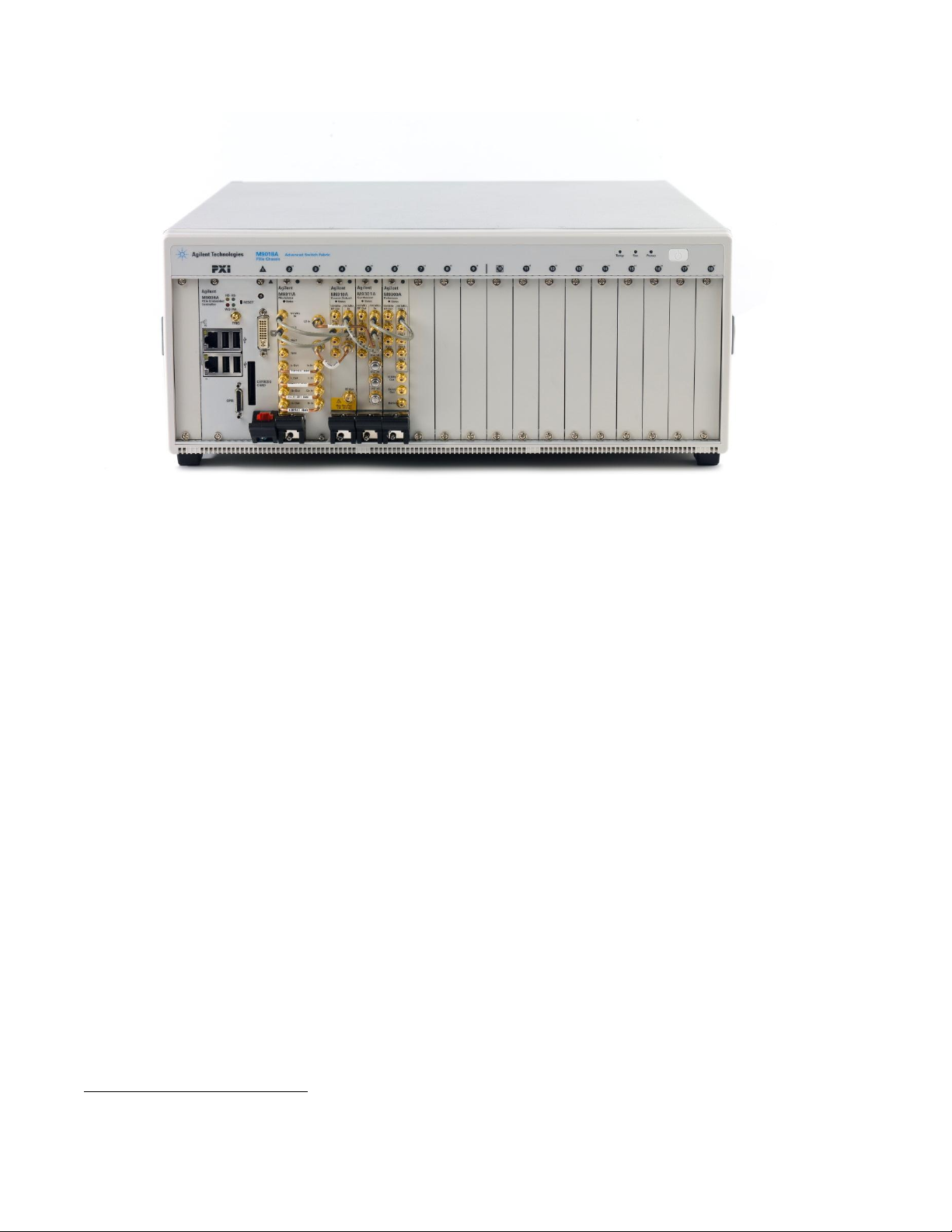
modular instruments to make accurate and traceable measurements. Figure 1 shows an example of a
PXI modular chassis with several modules inserted into it and filler panels covering the unused chassis
slots.
2013 NCSL International Workshop and Symposium
Page 2
1
Figure 1. PXI Modular Instrument.
Modular platforms provide distinct advantages for testing. The modular system chassis supplies
mechanical support, power, cooling, and communication/control services to the modular instruments.
Since these functions and services are common to, but separate from the individual modules, the
modular instruments are themselves compact. This allows for small floor space requirements, plus the
ability to quickly add, remove or replace modular instruments.
Taking full advantage of the modular platform, however, does present unique challenges when
calibrating individual modular instruments. When removing a modular instrument from the chassis and
sending it to the calibration laboratory, not all of the functional components that affect measurement
accuracy travel with the instrument. Additionally, the operating environment for an individual
instrument in the use location may be significantly different from the operating environment in the
chassis at the calibration laboratory. Finally, specifications may cover the accuracy of multiple modules
working together as a system.
The remainder of this paper examines the calibration issues associated with modular instruments and
provides recommendations for dealing with them.
2. Environmental Conditions
Almost without exception, instrument specifications include the environmental conditions over which
the instrument shall meet its accuracy specifications. This is true for all instruments, not simply modular
instruments. ISO/IEC 17025 [1] places a requirement on calibration laboratories to ensure the
environmental conditions of the laboratory meet the requirements of the instrument calibration and do
not adversely affect the results1. What does this mean for modular instruments? Even while holding the
ambient conditions outside the modular chassis constant, the ambient conditions for individual modular
ISO/IEC 17025:2005 section 5.3.1.
2013 NCSL International Workshop and Symposium
Page 3

instruments depend on several factors (see Webb [2]). The total number of modules inserted into the
2
chassis greatly affects the amount of heat the chassis must dissipate. The chassis houses cooling fans
and the system integrator sets the fan speed. Additionally, system integrators have available air inlet kits,
slot blockers and filler panels (see Figure 2).
Figure 2 PXI Air Inlet Kit, Slot Blockers and Filler Panels.
Air inlet kits and slot blockers insert into open chassis slots and affect the airflow within the chassis.
Filler panels cover open slots, which also affect airflow. Manufacturers of modular instruments may
specify, or simply recommend, that air inlet kits, slot blockers or filler panels are used in open chassis
slots. The use of these devices and the ability to control fan speed gives system integrators maximum
flexibility when deciding how to best cool the chassis. As a final point, the cooling operation of one
manufacturer’s chassis may be materially different from another manufacturer’s chassis.
The cooling design for a modular system, therefore, depends on the specific requirements of a given
system and the system integrator’s decisions. This translates into a potentially wide range of
environmental conditions for modular instruments even for given ambient conditions outside the chassis.
That is, knowing ambient environmental conditions outside the chassis is not necessarily a good
indicator of the ambient environmental conditions for individual modules. This is an important point if
modular instrument calibration occurs in a different chassis, with potentially a different configuration,
from modular instrument intended operation. Manufacturers do address this issue, for example [3], by
specifying both the ambient temperature requirements outside the chassis and the temperature
requirements as measured internally by the modular instrument.
ISO/IEC 17025 requires test reports and calibration certificates to include the environmental conditions
that influence the measurement results2. For modular instruments, where the system configuration
affects the environmental conditions for individual modules, this requirement extends to relevant
environmental conditions inside the chassis.
3. Operating Software
For non-modular instruments, the controlling software, or firmware, is typically inseparable from the
instrument. However, for modular instruments, the controlling software is not stored in the instrument.
This is not to say that modular instruments do not perform computations as they may perform internal
calculations. The controlling software for modular instruments is the software layer that allows control
of the instrument hardware. This software is referred to as the instrument driver and it resides on an
ISO/IEC 17025:2005 sections 5.10.3.1.a, 5.10.3.2.e, and 5.10.4.1.a.
2013 NCSL International Workshop and Symposium
Page 4

external computer. Instrument control is either through automated test software written by the test
3
designer that uses the instrument driver, or through the instrument driver’s graphical user interface. To
use a modular instrument, it must be inserted into the chassis, the chassis must either be connected to a
computer, or, a computer must be inserted into the chassis, and, the instrument driver must be installed
on the computer.
The instrument driver can affect the accuracy of the modular instrument. That is, the measured results
for a given modular instrument can change when using a different revision of the driver.
When sending a modular instrument to a calibration laboratory, the calibration laboratory likely uses its
own computer to control the modular instrument. Therefore, the instrument driver must be installed at
the calibration laboratory. Manufacturers do periodically update instrument drivers. Ideally, both the
calibration laboratory and the user of the modular instrument take care to ensure instrument drivers are
up to date. This is not always feasible, however. For example, the qualification of the end-use system
may assume a specific revision of the instrument driver, and the cost of re-qualification may preclude
using different instrument driver revisions. To ensure a valid calibration, it is best to calibrate using the
same driver version as used during modular instrument intended operation. Given the impact instrument
drivers have on the measured results, reporting the instrument driver revision on the calibration report is
necessary.
4. Multi-module Instrument Accuracy
Modular instruments fit one of several form factors. Single-module, one or two slot-wide instruments
are common. For larger and perhaps more complex instruments, a modular design allows for
instruments consisting of multiple modules. That is, a multi-module instrument. Figure 1 shows an
example of a chassis containing a multi-module instrument with modules of varying widths.
For many multi-module instruments, instrument accuracy depends on a combination of modules. That
is, removing and replacing any one of the modules of a multi-module instrument may affect instrument
accuracy. While an advantage of the modular system allows removing and replacing any module within
a chassis, care must be taken to ensure calibrated accuracy of a multi-module instrument. One way to
manage multi-module instrument calibration is to calibrate the interdependent modules as a set. The
advantage of this strategy is that it results in very high confidence that the multi-module instrument, as a
set of modules, performs with a quantifiable accuracy.
ISO/IEC 17025 requires an “unambiguous identification of the item(s) tested or calibrated3.” Multimodule instruments do not typically have an identifier for the set of interdependent modules; rather,
each module within the set has its own unique identifier. Therefore, an identifier for the set must be
created. An identifier derived from each module’s unique identifier is sufficient. With this scheme,
however, replacing one of the modules from the set changes the unique identification of the set, which
would then require a new calibration. This is as it should be. If changing a module of a multi-module
instrument affects the accuracy, then any previous calibration of that multi-module instrument no longer
applies to the current set of modules.
To help manage multi-module instrument calibrations, manufactures have added “electronic calibration
manager” features to modular instruments (for example, see [4]). With an electronic calibration
manager, calibration information is stored in the modules giving a unique identification to the
interdependent modules and allows for automatic detection if any module from the set is removed and
ISO/IEC 17025:2005 section 5.10.2.f.
2013 NCSL International Workshop and Symposium
Page 5

replaced. Additionally, electronic calibration managers allow setting calibration intervals and provide
automatic end-of-period reminders.
Calibrating interdependent modules as a set somewhat constrains the flexibility of modular systems.
Namely, replacement of a module from a multi-module instrument is possible; however, it becomes
necessary to calibrate the multi-module instrument after doing so. An alternative to calibrating multimodule instruments as a set is to calibrate each module individually. The multi-module instrument
accuracy is then determined from the individual module calibrations using the methods of the GUM [5].
This allows individual module calibration to occur at different times and allows module replacement
without the need to recalibrate the multi-module instrument as a set.
The GUM methods require a measurement equation, and in this case, one that models the multi-module
instrument accuracy as a function of individual module accuracy. The measurement equation may or
may not be available from the multi-module instrument manufacturer. It may be challenging to achieve
the specified accuracy of the multi-module instrument when propagating uncertainties from individual
module calibrations, and is one reason manufacturers may require calibration of the module set. It is
likely that the uncertainty when calibrating the multi-module instrument as a set is better than the
combined uncertainties propagated from each individual module calibration. However, if the combined
uncertainty meets the needs of the intended use of the multi-module instrument, even if the uncertainty
is greater than the specified accuracy, then managing calibrations this way may be practical.
Regardless of the method for managing multi-module instrument calibrations, some amount of
disassembly and reassembly may be necessary after calibration. Interconnections and cabling between
modules is common with multi-module instruments as can be seen in Figure 1. Clearly, proper
reassembly and verification is critical. Many multi-module instrument drivers include self-check
routines that will ensure proper operation after reassembly.
5. In situ Calibration
When in situ calibration is possible or practical, it addresses many of the presented issues. In situ
calibration means that calibration takes place with modular instruments in the same chassis and with the
same or nearly the same environmental conditions as the environmental conditions during the intended
use. Disassembly and reassembly is avoided or minimized. It is possible to sidestep instrument driver
revision issues by employing the same computer during calibration as is used for the intended use.
Multi-module instrument considerations remain, however. In situ calibration has little bearing on
calibrating interdependent modules as a set versus calibrating individual modules and propagating
uncertainties.
Given modular systems, is possible to insert or add calibration standards into the modular chassis as
suggested by Manor and Dewey [6]. In this way, the standards modules in the chassis enable in situ
calibration of the other modular instruments in the same chassis. This approach provides several
benefits in addition to the benefits of in situ calibration. The presence of calibration standards in the
chassis provides maximum flexibility as to when to calibrate, can minimize downtime, and, with
dedicated resources, the calibration can be tailored to the specific measurement requirements of the
system. However, the calibration standards themselves require their own calibration and are subject to
the same calibration challenges as any other modular instrument. Nonetheless, this strategy offers
significant flexibility for managing multi-module instrument calibrations.
2013 NCSL International Workshop and Symposium
Page 6

6. Summary
If the objective is to make accurate and traceable measurements with modular instruments or simply to
provide confidence that modular instruments are operating within tolerance, then special attention
should be giving to following modular instrument calibration issues.
Environmental conditions for individual modules are highly dependent on system configuration.
Modular instruments may have unique environmental requirements that must be met during
calibration and reported on the calibration report.
Instrument drivers may affect modular instrument accuracy. Care must be taken to ensure the
use of the correct driver during calibration and the driver revision should be included on the
calibration report.
Special consideration must be made to ensure valid calibration for multi-module instruments.
This may require calibration of interdependent modules as a set and assigning the set a unique
identification. Alternatively, the GUM method of propagation of uncertainty from the
calibration of individual modules may allow quantifying multi-module instrument accuracy. In
either case, after any disassembly and reassembly, operational verification is very important.
Acknowledgements
The authors would like to acknowledge Ben Smythe of Agilent Technologies for his contribution to this
paper.
References
[1] General requirements for the competence of testing and calibration laboratories, ISO/IEC
17025:2005, International Organization for Standardization, Geneva, Switzerland, 2005.
[2] Webb, P., Best practices for successfully managing long-term PXI deployments, Autotestcon, 2008
IEEE , vol., no., pp.453,457, 8-11 Sept. 2008.
[3] Agilent M9381A PXIe Vector Signal Generator Datasheet, page 5, 5991-0279EN, Agilent
Technologies, March 28, 2013 (http://cp.literature.agilent.com/litweb/pdf/5991-0279EN.pdf).
[4] Comprehensive Services For Your PXIe Signal Generators, Marketing Brochure 5991-1799EN,
Agilent Technologies, January 16, 2013 (http://cp.literature.agilent.com/litweb/pdf/5991-
1799EN.pdf)
[5] Guide to the Expression of Uncertainty in Measurement, (GUM), BIPM, IEC, IFCC, ISO, IUPAC,
IUPAP, OIML – International Organization for Standardization, Geneva, Switzerland, 1995.
[6] Manor, D.; Dewey, M., Instrument certification as part of a modular test platform architecture,
Autotestcon, 2007 IEEE , vol., no., pp.50,56, 17-20 Sept. 2007
2013 NCSL International Workshop and Symposium
 Loading...