

Page 1

HP mc-Series 5042 Rack
Site Preparation Guide
Table of contents
Preface ............................................................................................................................................... 2
Safety and regulatory information .......................................................................................................... 2
Notational conventions ......................................................................................................................... 2
Acronyms and abbreviations ................................................................................................................. 2
Safety in material handling.................................................................................................................... 3
Japanese notice ................................................................................................................................... 3
Chapter 1: Overview ............................................................................................................................ 4
Product overview .................................................................................................................................. 5
Key MCS 5042 components ................................................................................................................. 6
MCS 5042 specifications ...................................................................................................................... 9
Chapter 2: Facility planning for MCS 5042 implementation .................................................................... 10
Overview .......................................................................................................................................... 10
Space and positioning considerations .................................................................................................. 11
Electrical considerations ...................................................................................................................... 24
Coolant source planning ..................................................................................................................... 29
Coolant requirements .......................................................................................................................... 44
Environmental considerations ............................................................................................................... 53
Control system ................................................................................................................................... 53
Before installing and running active components .................................................................................... 53
Appendix A Forms and checklists ......................................................................................................... 54
Delivery survey form ........................................................................................................................... 54
Pre-installation checklists ..................................................................................................................... 55
Appendix B: Conversion factors and formulas ....................................................................................... 57
Conversion factors for refrigeration ...................................................................................................... 57
Metric equivalents .............................................................................................................................. 57
kVA conversions ................................................................................................................................ 57
Formulas ........................................................................................................................................... 57
Glossary ........................................................................................................................................... 58
Legal notices ..................................................................................................................................... 60
Restricted rights legend ....................................................................................................................... 60
For more information .......................................................................................................................... 60
Page 2

Preface
Safety and regulatory information
For your protection, this product has been tested to various national and international regulations and
standards. The scope of this regulatory testing includes electrical/mechanical safety, radio frequency
interference, acoustics, and known hazardous materials. Where applicable, approvals obtained from
third-party test agencies are shown on the product label.
Notational conventions
Warning:
Warnings highlight procedures or information necessary to avoid injury to
personnel. The warning should tell the reader exactly what will result from
what actions and how to avoid them.
Caution:
A caution highlights procedures or information necessary to avoid damage
to equipment, damage to software, loss of data, or invalid test results.
Note:
A note highlights supplemental information.
Acronyms and abbreviations
Acronym/
abbreviation Definition
BSPP British Standard Pipe Parallel NPT National Pipe Thread
CHWS Chilled water supply NPTF American National taper pipe thread for
CHWR Chilled water return MCS 5042 mc-Series 5042 Rack
CTO Configure to order PTFE Polytetrafluoroethylene
FRU Field Replaceable Unit TN Grounding Grounding specification
HEX Heat Exchanger Unit GOW Gas, oil, water
LAHJ Local Authority Having Jurisdiction WSP Water steam pressure
Acronym/
abbreviation Definition
dry-seal pressure-tight joints
2
Page 3
Safety in material handling
Warning:
Do not lift the cabinet manually. To avoid physical injury you must use a
mechanical lifting device.
Warning:
Use care when working with hazardous voltages. This equipment might be
configured with dual input line sources. Hazardous voltages and energy
might be present even after the removal of a single input source. Trained
service personnel must follow the service guidelines. Verify that the
differences in ground sources meet LAHJ.
Warning:
Do not stand in front of the equipment as it is rolled off the pallet onto the
ramps. When removing the equipment from the shipping pallet, follow the
guidelines specified in the Installation Procedures section of the appropriate
equipment guides.
Japanese notice
3
Page 4
Chapter 1: Overview
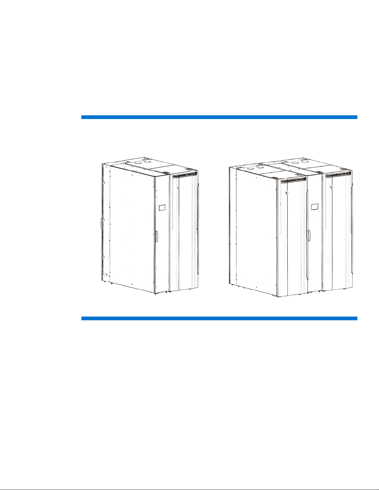
A: Single Rack (standard) Configuration
B: Dual Rack Configuration
The HP mc-Series 5042 Rack (“MCS 5042”) is a supplemental cooling system for the data center that
offers two configuration options:
• Preconfigured with a single HP 642 1200mm IT rack enclosure (Figure 1A)
• Configured to support two HP 642 1200mm IT rack enclosure (The second IT rack is a field-
installed option, as shown in Figure 1B).
Throughout this chapter, to ensure that all data is considered for a successful site preparation, the
various specifications and aspects of the system are defined.
Figure 1: MCS 5042 configuration options
4
To provide dedicated cooling of servers and other IT equipment, the MCS 5042 integrates with the
facility chilled water plant or a dedicated chilled water loop. To supply the MCS 5042, HP
recommends that you install a dedicated cooling loop. The system provides cooling, recirculation, and
condensation management, and it requires a small amount of AC electric power. Internal monitoring
and control sensors assure server inlet air set points are achieved and provide constant performance
feedback through local and network interfaces.
Page 5
Product overview
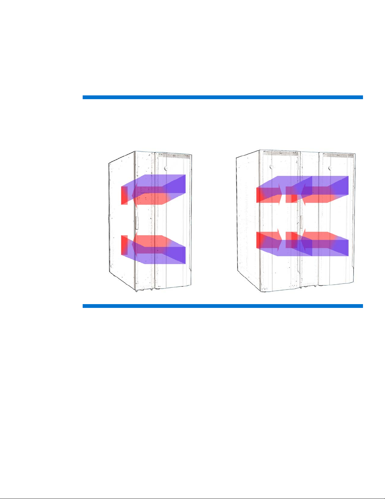
A: single -rack (standard) configuration
B: Optional field-installed dual-rack configuration
The MCS 5042 is a modular, distributed cooling solution that removes the high levels of heat
generated by current advanced server and mass storage systems. The MCS 5042 provides a uniform,
effective, affordable, and distributed cooling approach for servers and other IT equipment installed in
server racks. The MCS 5042 is a closed-loop cooling system integrated as part of a nonventilated
server enclosure, in contrast to a conventional ”open” server enclosure with perforated front and rear
doors.
Figure 2: MCS 5042 air flow
The special horizontal air flow of the MCS 5042 fully supports the industry-standard front-to-back
cooling principle (such as cold air drawing into the front of the server and warm air being expelled
out the rear of the unit). All devices receive adequate and evenly distributed cool air, regardless of the
mounting position within the enclosure. The MCS 5042 distributes precisely cooled, targeted air flow
evenly across the front of the IT equipment. Next, warmed air is channeled from the rear of the IT
equipment into the side-mounted MCS 5042, cooled, and then re-circulated back to the front of the
equipment stack. In the dual-rack IT configuration, the left side panel of the MCS 5042 cooling unit is
removed to provide cooling and air recirculation for an additional IT rack. In this configuration, the
cooling capacity of the MCS 5042 is divided between the two IT racks.
5
Page 6

Key MCS 5042 components
The MCS 5042 key components that work together to provide cooling performance include:
• Main breakers—Provides power for the MCS 5042 through circuit breakers (do not control power
at the input panel*).
• Heat Exchanger Module (HEX)—Includes an air-to-water heat transfer device specially created for
demanding data center environments.
• Display—Provides general cooling unit status.
• Management module—Provides users with web-based capabilities to set, monitor, and control
temperature within the modular cooling unit and displays the health of the unit.
• Fan controller—Operates the fans, according to the cabinet air temperature.
• Air bleeder valve—Enables air to bleed out of the system manually when coolant is initially filled.
• Water controller—Senses for condensation, leaks, water temperatures, flow rate, and the status of
the water valve and reports this information to the management module.
• AC input/network connection—Provides primary and (if available) secondary AC input connections
and management network interface.
• AC transfer switch—Provides dual-AC power with a fail-over feature for redundancy.
• Fans—Provides circulation of cooled air through the computer equipment rack.
• Water group—Includes the water valve, flow meter, check valve, and temperature sensors.
A condensation pump with overflow and condensation lines connects to the water group. Each
MCS 5042 has one water group.
* If the MCS 5042 is still connected to a power source, voltage is applied before the circuit breakers at the input panel.
6
Page 7
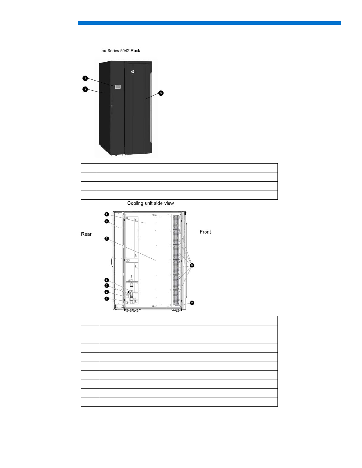
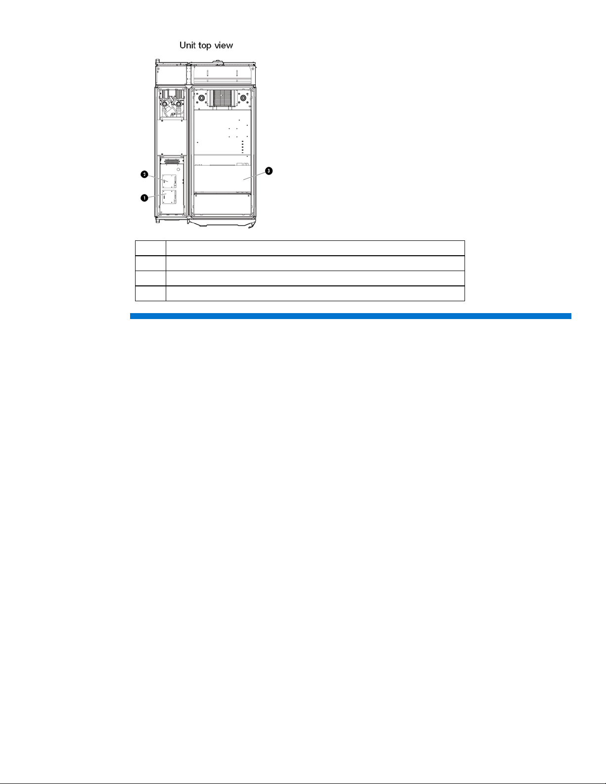
Item
Reference
Figure 3: MCS 5042 component locations
1 Cooling unit
2 User display
3 IT rack
Item Reference
1 Condensation pump
2 Condensation pump controller
3 Control valve
4 Flow meter
5 Humidity sensor
6 Rear extension
7 Heat exchanger unit
8 Fan units
9 Management module
7
Page 8
Item Reference
1 Water module
2 Fan module
3 AC transfer switch
8
Page 9

MCS 5042 specifications
Physical specifications
Table 1: MCS 5042 physical specifications of a standard single rack and server cabinet configuration
Parameter
Height 2285 mm (90 in) 2007 mm (79 in) 2007 mm (79 in)
Width 1219 mm (48 in) 904 mm (35.6 in) 904 mm (35.6 in)
Depth 1829 mm (72 in) 1510 mm (59.5 in) 1510 mm (59.5 in)
Weight 732 kg (1614 lb) 1 478 kg (1054 lb) 2 1521 kg (3353 lb) 3
1
Weight for a completely packaged system with unpopulated server rack
2
Weight for an unpackaged system with unpopulated server rack
3
Approximate weight for an unpackaged CTO system (Actual weight varies, according to configuration.)
Note:
If the top shipping bracket interferes with deploying the MCS 5042, you
can remove it. With the top shipping bracket, the total height of the
unpackaged system is 2069 mm (81.5 inches).
Packaged system
(as shipped on pallet)
Unpackaged system
(off pallet, unwrapped)
Unpackaged
CTO system
Electrical specifications
Table 2: MCS 5042 electrical specifications
Parameter Value Comments
Operating voltage 208/230 VAC +/- 10%, 50/60 Hz
AC line phase Single
Maximum input current 18 A Per line cord
Maximum inrush current 200 A Per line cord
Dropout/hold-up time at minimum line voltage 20 ms
Transfer time of AC transfer switch 2 s
Circuit breaker rating LAHJ Per cord
Power factor > 0.95 At all loads
Ground leakage current < 19.4 mA Per line cord
Rated power consumption 2800W Steady state
Power cords
(included with the MCS 5042)
208 V, 20 A NEMA L6-20-to-Procon
700105 (Qty 2)
250 V, 16 A IEC 309-to-Procon 700105
(Qty 2)
9
Page 10

Chapter 2: Facility planning for MCS 5042 implementation
Overview
The MCS 5042 offers an incremental data center cooling solution, capable of cooling 50 kW of heat
from one IT rack or two IT racks. The two basic methods to deploy the MCS 5042 are as a
standalone unit or placed in a row adjacent to other MCS 5042 or standard equipment racks.
In planning water supply and design, take into consideration short-term and long-term needs for
cooling. Immediate supply needs must meet the specifications and target cooling requirements, based
on the parameters defined in this site preparation guide. In anticipation of future heat loads, design
and install dedicated loop chilled water piping, based on specific cooling load increments (such as
50 kW or 250 kW), the specific number of MCS 5042 per row or loop, and other site build-out
planning parameters. As cooling, rack space, and equipment density requirements increase, you can
add MCS 5042 units to the chilled water system.
The chilled water piping system can be routed three ways:
• Routed overhead and the top into the cabinet
• Above the floor and connected through the rear of the cabinet
• Under the floor and routed through the raised flooring and through the bottom of the unit
Note:
Installation service for the MCS 5042 is order number UE005E.
Note:
For site evaluations and technical consulting for your site, see the HP
Services website:
http://www.hp.com/services/criticalfacilities
Note:
The implementation of the MCS 5042 aligns with Data Center Best
Practices. For more information, see Optimizing Data Centers for High-
Density Computing which can be found on the HP website:
http://h18004.www1.hp.com/products/servers/proliantstorage/r
acks/10000series/documentation.html
This chapter discusses key issues for site preparedness, including:
• Space considerations (for delivery, operation, and service) and other related considerations (such
as floor loading)
• Electrical considerations
• Coolant source options and quality considerations
• Other considerations
A complete site preparation checklist is provided in Appendix A
.
10
Page 11

Space and positioning considerations
The MCS 5042 is larger (and, when fully populated, heavier) than a standard 19-inch equipment
rack. Therefore, space required for maneuvering, operating, and servicing the MCS 5042 is greater
than standard-sized racks.
Delivery space requirements
You must ensure the facility has adequate space to receive and remove the MCS 5042 from the
shipping pallet. When unloading the MCS 5042, take into consideration the following:
• Forklifts must enter and transport the shipping pallet from the side.
• Delivery plans must include the possible removal of walls or door.
• A total length of approximately 6.1 m (20 feet) must be allowed to safely remove the MCS 5042
from the shipping pallet down the provided ramps.
• The packaged dimensions of the MCS 5042 preconfigured with a single IT rack are (including
shock pallet and cartons):
2285 mm (90 inches) height x 1219 mm (48 inches) width x 1829 mm (72 inches) depth
Maneuvering space requirements
When maneuvering the MCS 5042, use the following guidelines:
• Racks with casters must be moved with care. Sudden stops, excessive force, and uneven surfaces
might cause the product to overturn.
• Both the cooling unit and the IT rack have casters that are fixed at the front and swivel in the back
due to stability and safety concerns. Therefore it is easier to move the MCS 5042with the back as
the leading edge.
• For long, straight distances roll the MCS 5042 with the front, fixed casters leading. For better
mobility lead with the rear, swiveling casters.
• When rolling the MCS 5042, push firmly on the front doors frame and not the door mesh of the IT
rack. The points on where to push the MCS 5042 are marked by factory.
• Make sure the rooms and doors are large enough to accommodate the movement of the MCS
5042 cabinet into the data center.
• When transporting the MCS 5042 to a different building floor, be sure elevators have adequate
load capacity, floor space, and door clearance to accommodate the rack. The MCS 5042 pallet
can only be moved with forklifts from the side, which has a length of 1829 mm (72 inches).
• When transporting the MCS 5042 within a building, be sure that doorway thresholds are adequate
to hold the rack. HP does not recommend that you lift or transport the MCS 5042 by eyebolts that
are attached to the upper corners of the cabinet.
Warning:
To reduce risk of personal injury or damage to the equipment, a single
person must not attempt to move equipment racks alone. Obtain adequate
assistance to stabilize the rack during movement or hire professional
equipment riggers.
11
Page 12
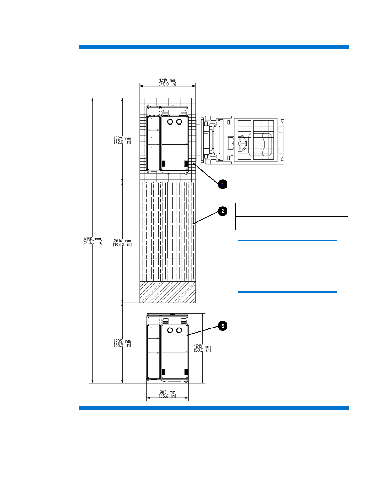
Figure 4 shows the maneuvering space required when unloading the MCS 5042 from a pallet. When
Item
Reference
1
MCS 5042 shock-pallet
2
3 piece ramp
3
HP mc-Series 5042 Rack
planning for moving the rack, use the delivery forms provided in Appendix A
.
Figure 4: MCS 5042 shipping package delivery and maneuvering space requirements for a single IT rack configuration
Caution:
HP recommends that a ramp angle of no
greater than 5° be used to move the MCS
5042 up or down elevations. Typical data
center ramps have a 5º angle (1 to 12
pitches).
12
Page 13
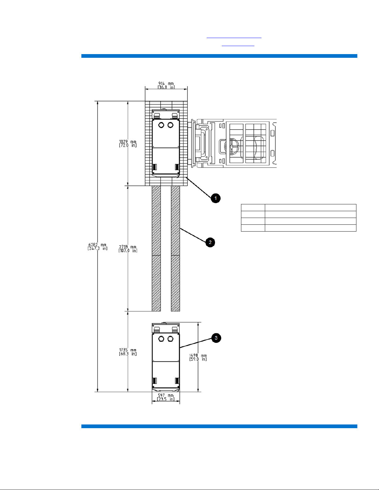
Figure 5 shows the maneuvering space required when unloading the HP MCS 5042 Expansion Rack
Item
Reference
1
MCS 5042 shock-pallet
2
4 piece ramp
3
HP mc-Series 5042 Expansion Rack
Kit (BW973A, available on the HP website at http://www.hp.com
) from a pallet. When planning for
moving the rack, use the delivery forms provided in Appendix A.
Figure 5: MCS 5042 shipping package delivery and maneuvering space requirements for the HP MCS 5042 Expansion Rack
13
Page 14
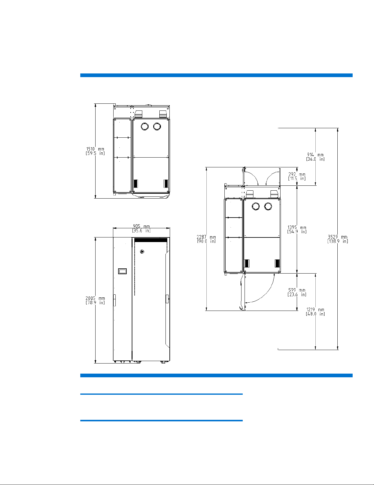
Operational space requirements
To provide space for internal airflow and housing of the cooling unit components, the MCS 5042 is
wider and deeper than conventional HP racks. HP recommends a minimum access space for the MCS
5042 in the standard single rack configuration be 1219 mm (4 feet) in the front and 914mm (3 feet)
in the rear as shown in Figure 6.
Figure 6: MCS 5042 operational space dimensions
14
Note:
With the top shipping bracket the total height is 2069mm (81.5 inches).
Page 15
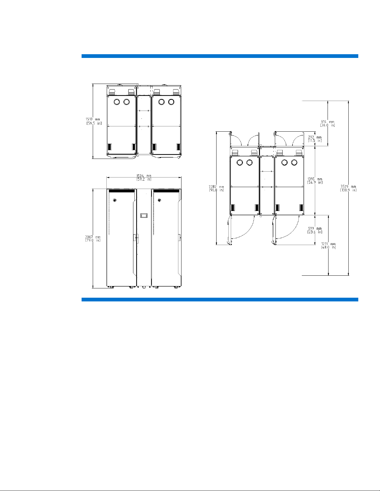
An HP MCS 5042 installed in a dual rack configuration requires approximately an additional 600
mm of width space to accommodate the second IT rack mounted to the left of the cooling unit, as
shown in Figure 7.
Figure 7: MCS 5042 operational space dimensions in a dual-rack configuration
System positioning
The MCS 5042 can be installed next to an existing or new row of HP Intelligent Series racks. Based
on facility design requirements, the cabinets can be arranged in a flush front (Figure 8A) or flush rear
(Figure 8B) configuration.
15
Page 16
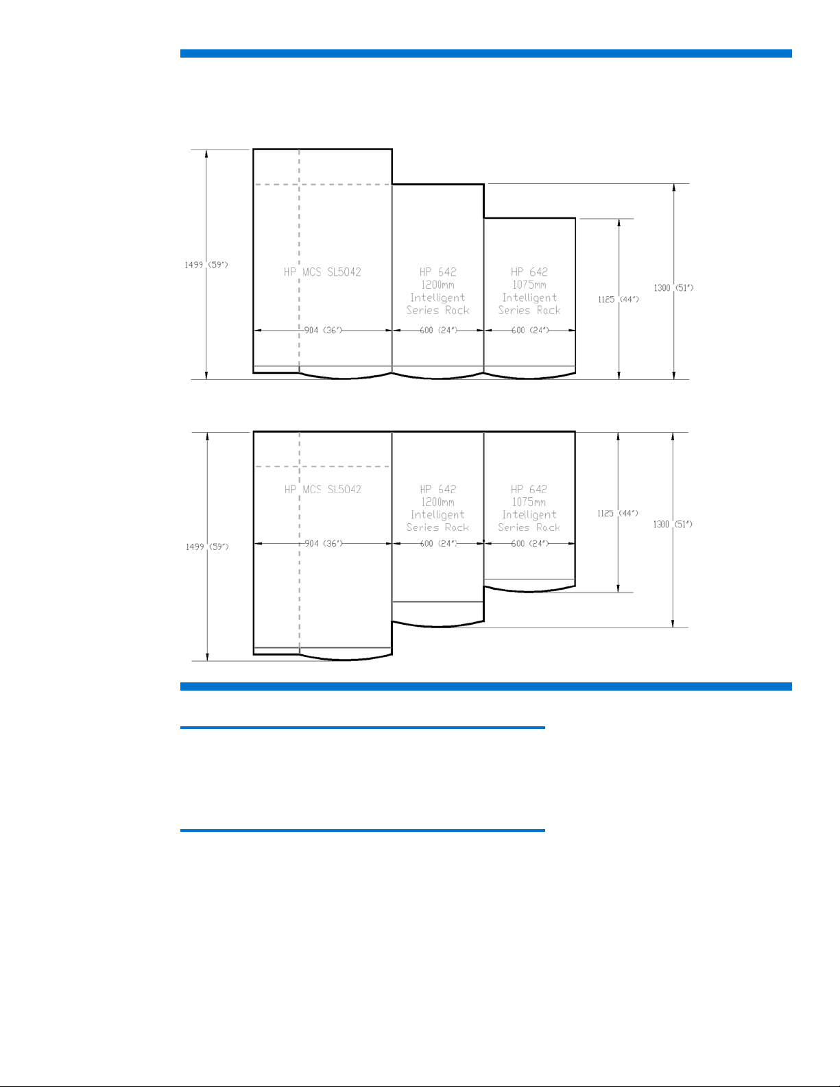
Figure 8: MCS 5042 arranged in a flush front configuration with a HP Intelligent Series rack row
8A: Flush front configuration
8B: Flush rear configuration
16
Note:
When arranging the MCS 5042 immediately next to a HP Intelligent Series
rack, front or rear door swing might interfere, depending on the
configuration. Equipment might require the removal of a door for full,
unimpeded access.
Cable openings
The MCS 5042 system has several useable cable openings at front top, rear bottom and rear top of
the IT rack. Figure 9A shows the size and position of the cable openings at the top and Figure 9B
shows the cable openings at the bottom in the standard single-rack configuration.
Page 17
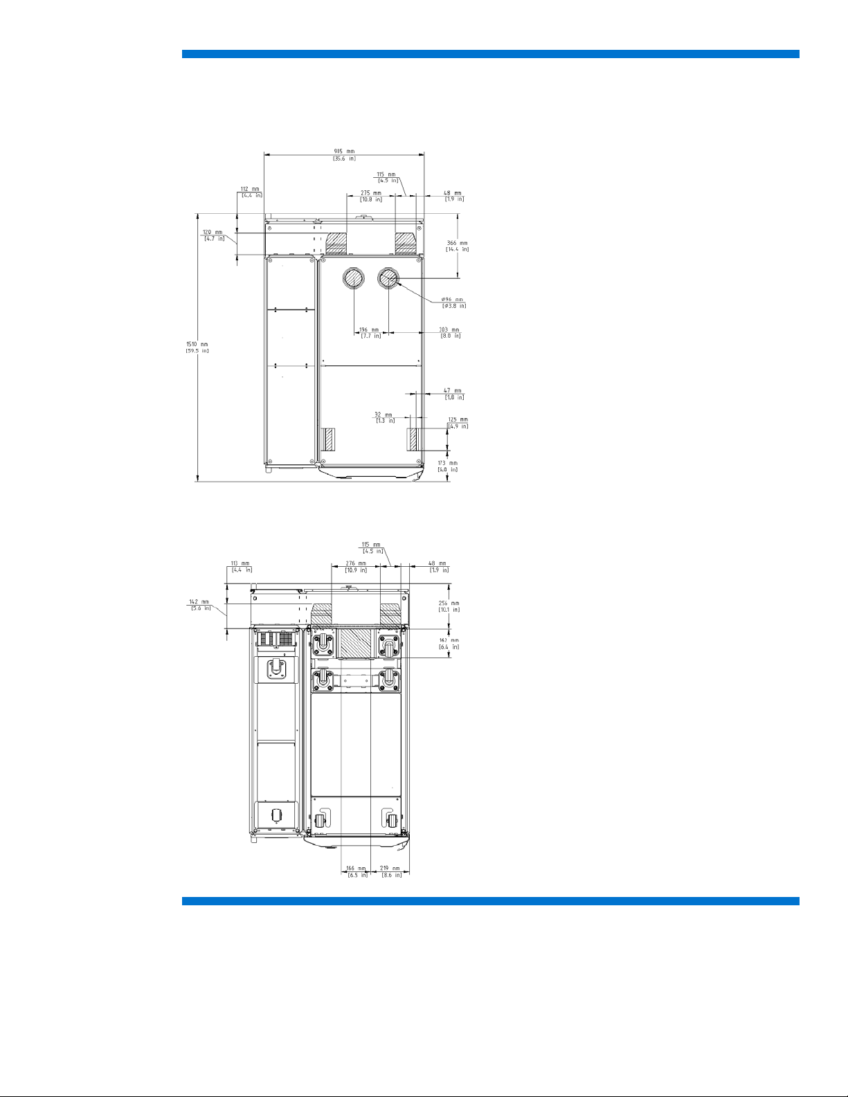
Figure 9: MCS 5042 cable openings in a single rack configuration
9A: Top view
9B: Bottom view
17
Page 18
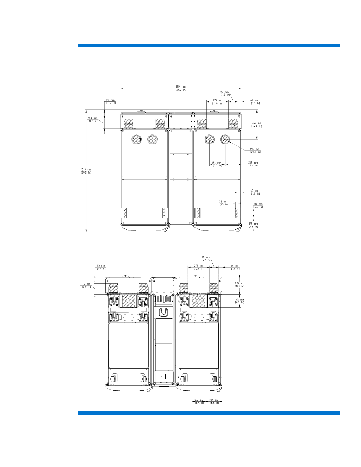
Figure 10 shows the size and position of the cable openings in a dual-rack configuration at the top
and at the bottom.
Figure 10: MCS 5042 cable openings in a dual rack configuration
10A: Top view
10B: Bottom view
18
Page 19

Cabinet leveling feet
The MCS 5042 system includes leveling feet and does not require fastening to the floor. To ensure the
enclosure remains stable during operation and servicing and to avoid personnel and equipment
damage, take care when the loading of the equipment.
Warning:
Static loading limits cannot be achieved if the rack is not on its leveling
feet, and rolled or pushed from its position.
Your floor weight capacity might not support the full static load capacity.
Check with your floor provider before loading. HP is not responsible for
floor damages due to floor overloading.
Note:
The IT rack of the MCS 5042 unit supports 1360 kg (3000 lb) of static
loads of IT equipment on the leveling feet.
Figures 11A and 12A show the locations of the cabinet leveling feet, and figures 11B and 12B show
an example of the locations on the raised floor. Ensure there is adequate floor and supporting
understructure remaining to support the load-bearing leveling feet, especially immediately around the
cutout. After the MCS 5042 is positioned in the proper location in the data center, the leveling feet
can be lowered into place to level and stabilize the MCS 5042.
Caution:
To reduce the risk of damage to the casters, make sure that the full weight
of the rack rests on the leveling feet, and not on the casters. The casters are
designed only as an aid in moving the rack into position. They are not
designed to support the weight of the rack, and the caster might become
damaged if relied on to support the rack.
19
Page 20

Figure 11: Cabinet leveling feet locations in a single-rack configuration
11A: Bottom view
11B: IT rack-side view
20
Page 21

Figure 12: Cabinet leveling feet locations in a dual rack configuration
12A: Bottom view
12B: Right IT rack-side view
Floor loading considerations
The computer room floor must be able to support the total weight of the installed servers as well as the
weight of the MCS 5042 as they are moved into position. The information presented in this section is
applicable to raised floor installations.
21
Page 22

Warning:
HP cannot assume responsibility for determining the suitability of a
particular raised floor system. The customer or local agencies must
determine installation requirements. An appropriate structural engineer must
verify any floor system under consideration for a server installation.
Raised floor loading is a function of the floor manufacturer’s load specification and the positioning of
the equipment relative to the raised floor grid. HP recommends the following guidelines:
• Some raised floor systems do not have grid stringers between floor stands. The lateral support for
the floor stands depends on adjacent panels being in place. To avoid compromising this type of
floor system while gaining under-floor access, remove only one floor panel at a time.
• Larger floor grids (bigger panels) are generally rated for lighter loads.
Table 3 can be used to calculate the weight load of each MCS 5042 unit, including installed
equipment for proper floor planning. The text in blue is included as an example. Weights can vary.
Table 3: MCS 5042 weight calculation
Qty.
Component Unit weight
MCS 5042 (with unpopulated server rack) 450 kg (992 lb) 1 450 kg (992 lb)
Component #1: HP ProLiant S6500 SL230s 91 kg (200 lb) 8 728 kg (1,600 lb)
(Multiply by) Total weight
Component #2:
Component #3:
Component #4:
Rack total:
Note:
The MCS 5042 has not been certified for seismic environments.
Table 4: Common floor loading terms
Term Description
Dead load The weight of the raised panel floor system, including the understructure.
Expressed in lb/ft
Design load The safe load that a floor panel can support on a 1 inch x 1-inch2 (25 mm x 25 mm2) area at the
panels weakest point (typically the center of the panel). This value is determined by taking the
lesser value of the maximum load that can be applied without failure divided by a safety factor of
two (ultimate load) or the load at which permanent damage begins to occur (yield point).
Rolling load The load a floor panel can support (without failure) when a wheel of specified diameter and
width is rolled across the panel.
2
(kg/m2).
22
Note:
If the specific floor being evaluated or considered is a product other than a
Tate All Steel 1250 System floor, you must contact the manufacturer of the
floor to evaluate if it meets the requirements described in this section.
Page 23

Table 5: Tate All Steel 1250 raised floor specifications
Weight
A
79 kg (174 lb)
B
458 kg (1010 lb)
C
385 kg (349 lb)
D
83 kg (183 lb)
E
457 kg (1008 lb)
F
375 kg (827 lb)
Item Rating
Dead load 34.2 kg/m2 (7 lb/ft2)
Design load 1 567 kg (1,250 lb)
Rolling load 227 kg (500 lb)
1
Similar to concentrated load
Note:
The IT rack of the MCS 5042 can carry a static load of up to 1,360 kg
(3,000 lb).
Note:
In Figures 13 and 14, the load is in the center of the IT racks. Due to
adjacency, the leveling feet in points B and E in Figure 13 and points B, C,
F, and G in Figure 14 are combined to one concentrated weight.
Figure 13: Weight distribution on the leveling feet locations in a single rack configuration
23
Page 24

Weight
A
385 kg (849 lb)
B
455 kg (1003 lb)
C
458 kg (1010 lb)
D
385 kg (849 lb)
E
375 kg (827 lb)
F
457 kg (1007 lb)
G
457 kg (1007 lb)
H
375 kg (827 lb)
Figure 14: Weight distribution on the leveling feet locations in a dual rack configuration
Caution:
To reduce the risk of damage to the casters, make sure that the full weight
of the rack rests on the leveling fee, and not on the casters. The casters are
designed only as an aid in moving the rack into position. They are not
designed to support the weight of the rack, and the casters might become
damaged if relied on to support the rack.
Electrical considerations
The MCS 5042 provides two Walther Procon A5 series AC input connections and ships with two sets
of power cords for connecting to redundant AC power busses, if available. Only one power cord is
necessary for operation. The second cord can be connected to a redundant AC power bus to improve
system availability by protecting against power source failures or accidentally tripped circuit breakers.
Note:
Electrical practices and suggestions in this guide are based on North
American practices. For regions and areas outside North America, local
electrical codes take precedence over North American electrical codes. For
example, HP recommends that the protective ground conductor be green
with yellow stripes. This requirement is a North American directive and
does not override the local code requirements for a region or areas outside
North America.
24
Page 25

Note:
The power requirements discussed in this guide are for the fans and
electronics for the MCS 5042 only. Data processing components such as
servers, storage, and network devices must be considered separately,
based on individual power requirements.
System grounding
HP server systems require two methods of grounding: power distribution grounding for safety, and
high-frequency signal grounding for equipment performance. Power distribution grounding involves
the main building electrical service entrance, electrical conduit, facility power panels, and equipment
cabinets (including the MCS 5042), which must be grounded, using green/yellow insulated wire
conductors according to the applicable electrical codes. High-frequency grounding consists of using
ground return conductors for intra-cabinet and inter-cabinet signal interconnects, as well as chassis
and cabinet grounding.
For MCS 5042 and server systems installed on a raised floor, the floor assembly must be electrically
grounded to form a complete ground grid. An optimum raised-floor grounding solution is shown in
Figure 15.
Each floor panel must have at least one supporting pedestal grounded to the power panel and
another pedestal grounded to the MCS 5042. The central ground connection of the MCS 5042 is
located in the bottom rear of the IT rack. This broadband solution provides grounding for maximum
safety and performance.
Figure 15: Central ground stud location inside the IT rack
25
Page 26
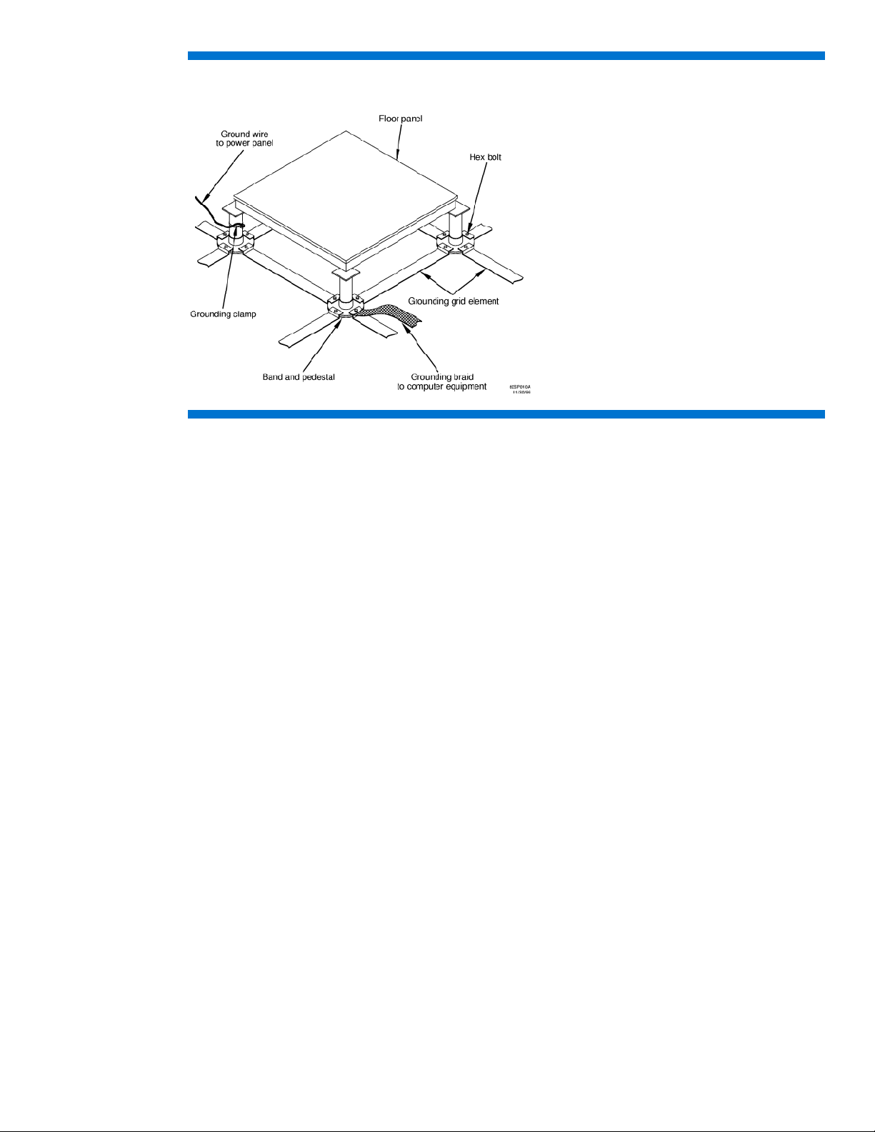
Figure 16: Raised floor grounding
Voltage fluctuations and outages
The MCS 5042 is designed to provide immunity to power outages of less than one cycle. However,
testing cannot conclusively rule out loss of service. Therefore, adherence to the following guidelines
provides the best possible performance of power distribution systems for HP equipment:
• Dedicated power source—Isolates the power distribution system from other circuits in the facility.
• Missing-phase and low-voltage detectors—Shuts equipment down automatically when a severe
power disruption occurs. For peripheral equipment, these devices are recommended but optional.
• Online uninterruptible power supply (UPS)—Keeps input voltage to devices constant and must be
considered if outages of one-half cycle or more are common. For more information, consult a
qualified contractor or consultant, as necessary.
The MCS 5042 can be protected from the sources of many electrical disturbances by using:
• An isolated power distribution system
• Power conditioning equipment
• Over-voltage and under-voltage detection and protection circuits
• Shielding to attenuate higher frequency radiated electrical energy
• Surge protective devices on power cables to protect equipment against electrical storms
26
Page 27

Electrical planning around water handling components
Because of the potential of forming condensate on non-insulated water connections or leaking water
connections around water-based cooling systems, a few issues must be considered during the
electrical planning:
• Water-proofed connectors
• Watertight conduits for cables
• Leak detection systems
Warning:
If water comes in contact with power cables, before cleaning up water in
this area, shut down the main breaker.
To identify water-proofed connectors, HP recommends looking at the IP-rating of the connector, based
on the international standard IEC 60529. Additionally, HP recommends a connector that is at least
rated IP 67.
Cable conduits are available in different styles depending on flexibility and materials. The common
materials are plastic, metal, nylon or mostly a composition of these materials. Watertight conduits are
available in both ways flexible or hard material, depending on the application.
A leak detection system for data center usually uses leak sensor cables, which are installed on the subfloor in a raised floor and connected to a facility management system.
Connecting to facility AC power
The MCS 5042 accepts AC power through two Walther Procon A5 series power receptacles located
at the top rear patch panel. The MCS 5042 ships with two sets of AC power cords for connecting to
redundant AC power busses, if available. Figure 17 shows the two types of power cords that ship
with the MCS 5042. The NEMA L6-20 power cord uses a NEMA L6-20 male plug for connecting to a
facility AC feed connector common to North America and Japan. The IEC 309 power cord uses an
IEC 309 male plug for connecting to a facility AC feed connector common in various international
regions.
Figure 17: MCS 5042 power cords
NEMA L6-20-to-Procon-A5 Power Cord IEC 309-to-Procon-A5 Power Cord
At least one power cord must be used for operation of the MCS 5042. To improve system availability,
the second cord can be connected to a redundant AC power bus. When the redundant power is
connected, the transfer switch assembly of the MCS 5042 provides switch-o
in
the event of power source failures or accidentally tripped circuit breakers.
ver to the active power bus
27
Page 28

Note:
The power cords of the MCS 5042 are 4 m (13.1 feet) long. After the
cords are connected to the MCS 5042 and routed down the rear of the IT
rack, approximately 2 m (6.6 feet) will be left to connect to the power
source.
When using only a single (primary) source for power, the AC power cord is connected to the left-most
receptacle (when viewed from the rear of the cabinet, labeled as AC1) as shown in Figure 18.
Figure 18: Single-source AC power connection
When redundant AC power is available, the redundant AC power cord is connected to the right
receptacle (labeled as AC2) as shown in Figure 19.
Figure 19: Redundant-source AC power connection
28
Page 29

Coolant source planning
A number of factors relating to a chilled water distribution system must be considered during the site
preparation process, including the following:
• Redundant water configurations (For more information, see Appendix B.)
• Type of water source (shared water or dedicated chilled water loop)
• Maximum and minimum temperatures of building chilled water plant, and target chilled water
temperature of dedicated loop based on total cooling capacity required and planned
• Viscosity of the chilled liquid, combined with the length and elevation changes in piping,
determined by selected route, which can affect the selection of pipe size
Caution:
The minerals and chemicals typically found in tap water can react with
metallic elements used in the MCS 5042. Electro-chemical reaction might
cause scaling, corrosion, leaks, and blockage, ultimately resulting in
reduced efficiency of the cooling system and even damage.
HP recommends that the water source for the MCS 5042 be a dedicated chiller unit or water-to-water
heat exchanger that enables line isolation, better control of individual systems, and regulated water
quality. The chilled water source for this loop is provided by one or more chiller systems. Advantages
of using a dedicated loop include:
• Easier scheduling of maintenance to either a building system or dedicated MCS 5042 loop
• Easier maintenance of water quality parameters in the dedicated closed loop
• Better temperature and flow regulation to guarantee the needs of the MCS 5042
• More flexibility to regulate water temperature in order to reduce the potential for condensation
The use of building chilled water for the MCS 5042 unit is possible under certain conditions.
However, consult with a qualified facilities design expert to determine whether this approach is
possible within your specific data center. Refer to the requirements for water quality, temperature, and
flow rate described in this section. Regardless of chilled water service approach, consult with a
qualified facilities design expert to analyze new and existing systems and specify new work to insure
water quality, temperature and water flow requirements can be met. The new work must meet all local
safety and building code requirements as well as the customer’s facility quality standards. Piping
drawings and schematics included here are diagrammatic to convey a conceptual understanding of
the MCS 5042 connection requirements.
29
Page 30
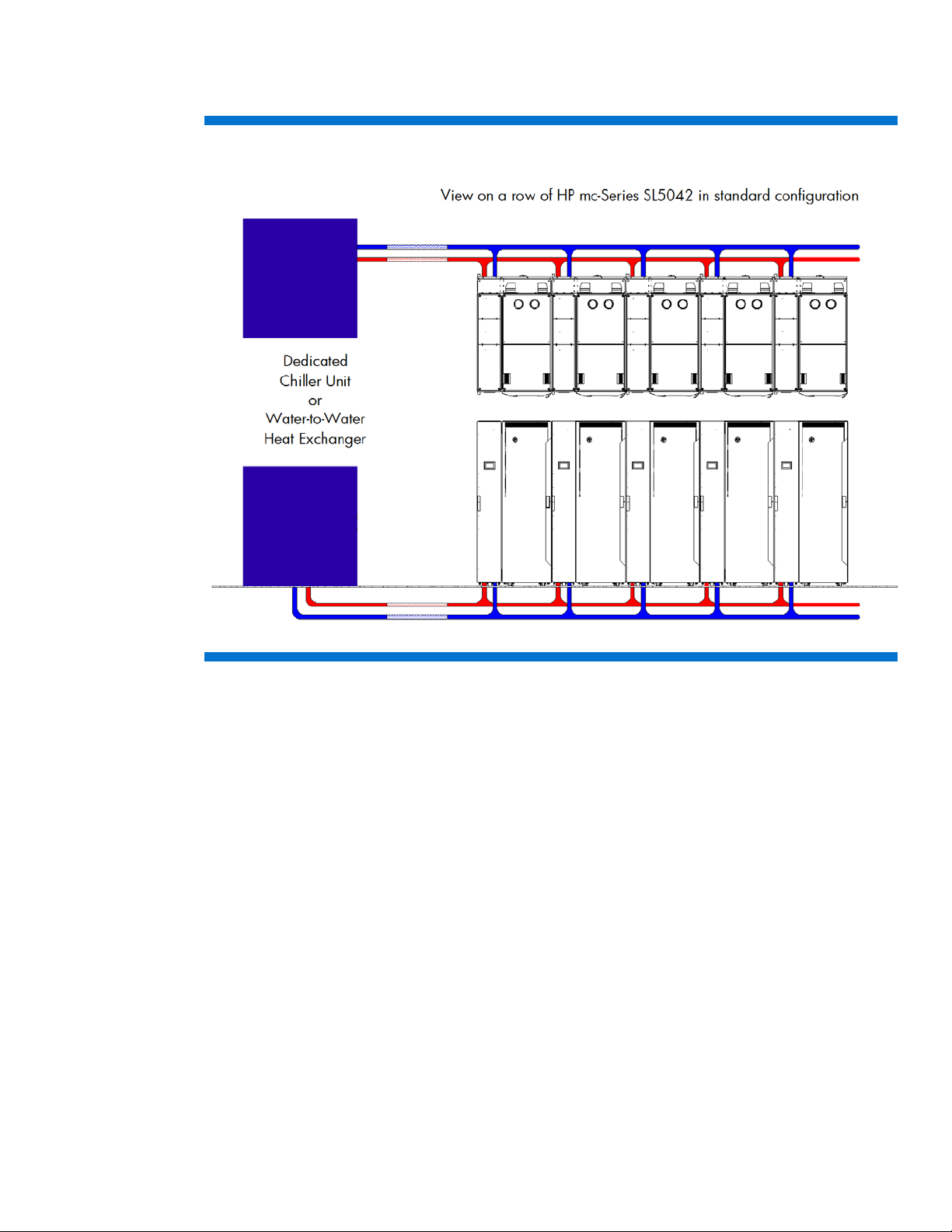
Figure 20 illustrates the MCS 5042 being supplied directly by a dedicated chiller unit or water-towater heat exchanger in a closed loop configuration.
Figure 20: Dedicated chiller unit directly supplying the MCS 5042
Plumbing considerations
A number of plumbing factors must be considered when installing the MCS 5042:
• (Highly recommended) Installing water shut off valves to enable infrastructure system flushing for the
inlet and outlet of each MCS 5042
• Flow rate and pressure capacity of chilled water plant input to the design of the facility feed line
and dedicated water loop pipe diameters
• Material compatibility within piping system to minimize the potential for electrochemical corrosion
and must be corrosion-resistant
• Minimization of elbows and other restrictions that increase flow resistance
• Insulation of piping to minimize risk of condensation and reduce incidental heating of supplied
chilled water
• Availability of a floor drain or reclamation system to capture system condensation
• Structural securing of piping to support weight of distribution network filled with water
• Water quality management, including particulate filtration, treatment, and flushing provisions, with
isolation valves for service requirements
• Availability and access to a data center leak detection system to monitor the infrastructure system
for leaks
• Air vents installed at the highest point in the pipe system (Each MCS 5042 has an air vent, but
additional vents in the supply piping system must be considered.)
30
Page 31
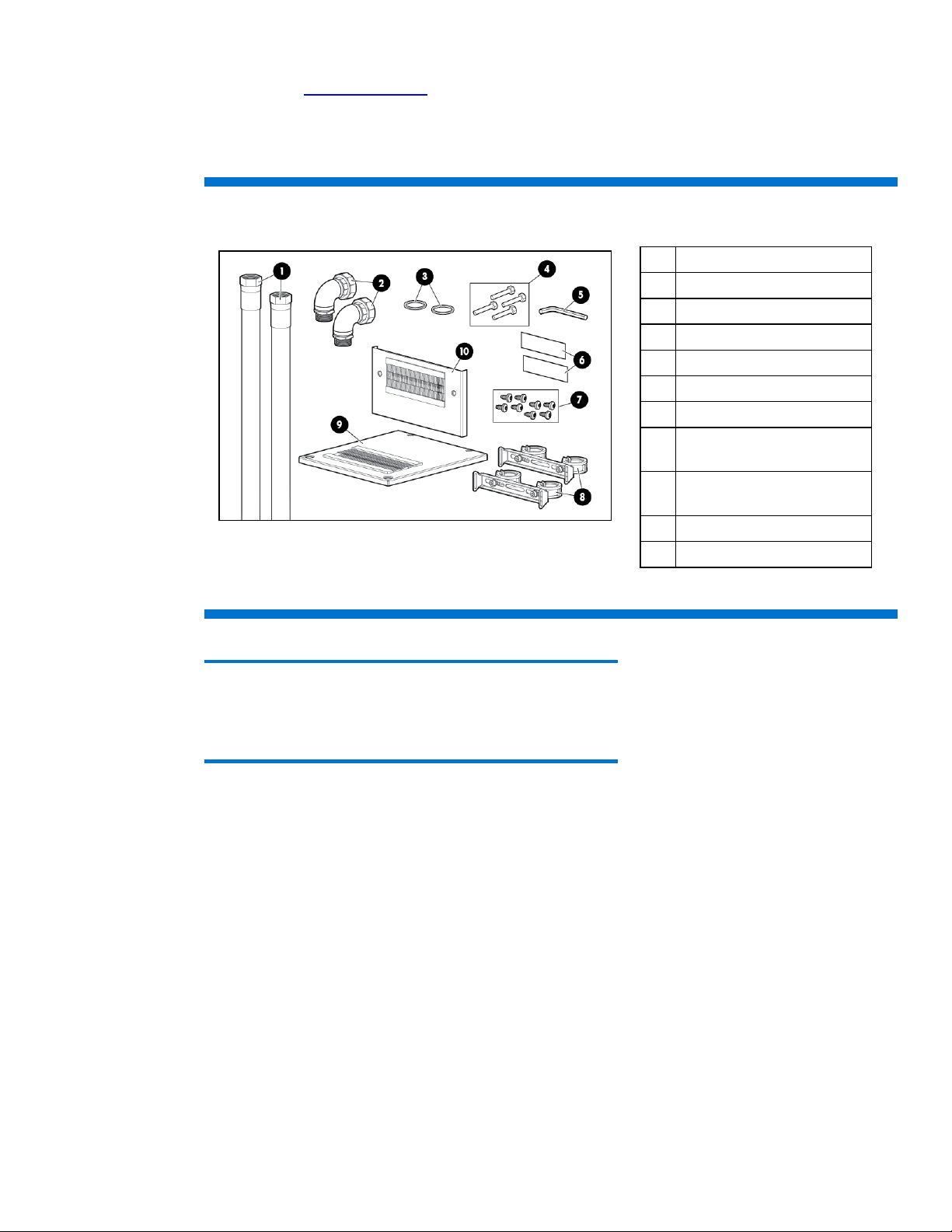
HP recommends the HP mc-Series 5042 Rack Water Hook-up Option Kit BW971A (available on the
*
HP website at
http://www.hp.com) for connecting the MCS 5042 to a facility chilled water system.
Each kit (Figure 21) includes the hoses and accessories required for connecting the facility supply and
return lines to the main inlet and outlet connections of an MCS 5042 unit and must be installed prior
to the delivery of an MCS 5042.
Figure 21: MCS 5042 Water Hook-Up Option Kit contents
Item Description (Quantity)
1 Main hose assembly* (2)
2 90-degree elbow assembly (2)
3 Viton gasket (2)
4 M6 screw (4)
5 5mm Hex L-key (1)
6 Warning label (2)
7 M5.5 x 10 self tapping screw
(8)
8 Hose mounting brackets with
Not drawn to scale. The actual length of the main hose is approximately 3.5 m (11.5 ft).
hose clamps (2)
9 Top cover plate (1)
10 Rear cover plate (1)
Caution:
You must properly connect the cabinet and facility cool water inlet and
warm water outlet hoses. The MCS 5042 does include a check valve to
prevent the reverse flow of coolant.
The MCS 5042 has the connecting fittings inside the unit, approximately 600 mm (24 inches) above
the floor on the rear side. It allows the main coolant hoses to be routed either down through the
cutouts in a raised floor (HP recommended) or up through openings in the top of the cabinet and
above the unit or through the back of the cabinet and above the floor as shown in Figure 22. The left
(blue) hose designates the chilled water supplied to the MCS 5042 and the right (red) hose is the
warm water exiting from the MCS 5042.
31
Page 32

A: Through raised floor cutouts
B: Above the floor
C: Above the unit
Figure 22: Main coolant line hookup options for the MCS 5042
32
Page 33

An HP Water Hook Up Kit must be installed prior to activating an MCS 5042. The length is
approximately 350 cm (138 inches) of flexible hose terminated with fittings at each end. The length
that is available outside the MCS 5042 depends on the type of connection that is desired as shown in
Figure 22.
Table 6: Available hose lengths outside the MCS 5042 by connection type
Connection type Approximate length supply hose Approximate length return hose
Bottom 280 cm (110 inches) 300 cm (118 inches)
Rear 280 cm (110 inches) 300 cm (118 inches)
Top 200 cm (79 inches) 180 cm (71 inches)
Figure 23 shows the location of the condensate (blue) and overflow (red) in the rear of the cooling
unit. The MCS 5042 includes both tubes for the hook up. Each tube is approximately 3 m (9 feet) in
length. The overflow hose has an inner diameter of 9 mm (0.35 in) and
n outer diameter of 8 mm (0.31 in). The preferred method of routing for all hoses is downward
has a
the condensation hose
at an angle of at least 3º (pitch of 0.6 inches per 12 inches), without loops, and away from the MCS
5042 cabinet. Pumped condensation and gravity-fed overflow hoses must be routed to a floor drain
or reclaim system.
Figure 23: MCS 5042 condensation and overflow hook up
Note:
Flexible attachment hoses are intended to allow for deflection in any
direction for equipment mounted on dynamic platforms, or for slight
relocation of cabinets.
33
Page 34

Note:
Alternate piping location
hose length limitation.
chilled water taps must approach laterally.
Do not locate piping connections or components
under the MCS 5042
Installation service for this MCS 5042 is order number UE005E.
Piping approaches
HP recommends the following methods for facility plumbing orientation with the MCS 5042:
• Direct rear approach
• Left rear approach
• Right rear approach
Note:
You can approach the MCS 5042 from the front with piping for the top
and bottom connection. However, this approach requires careful planning
for accessible component locations and hose attachments.
Figure 24 shows the recommended facility piping approaches to the MCS 5042.
Figure 24: Piping locations for the MCS 5042
Preferred piping location
Locate chilled water piping taps behind the MCS
5042 either under the floor or above the floor. The
Locating chilled water piping taps in front of the
MCS 5042 (under the floor) is possible. This option
requires careful planning due to the chilled water
34
Page 35

MCS 5042 hose openings
Figure 25 shows the dimensions and locations of the various hoses openings of the MCS 5042.
Figure 25: Hose openings for the MCS 5042
A: Bottom B: Rear
C: Rear
35
Page 36

Raised floor cutouts for MCS 5042
A complete MCS 5042 installation typically requires the following floor cutouts in a raised-floor
facility:
Standard rack configuration:
• One floor cutout for the chilled water hoses, drain hoses of the cooling unit
• One floor cutout for the power cords and data cables of the computer equipment rack (including
power supply to the MCS 5042). For details on the top openings, see the section Cable openings.
Raised floor panels vary in size globally, but all create virtual grid lines or seams where panels come
together. These seams are ideal for positioning computer racks on the raised floor. Figures 26 through
30 reference the locations of rack attributes aligned with raised floor seams to provide critical
dimensions for floor cutouts.
36
Page 37

Figure 26: Recommended floor cutouts (single rack configuration)—Option 1 (MCS 5042 cooling unit side flush to tile)
Note:
The wider opening in the back of the IT rack is optional.
Note:
The floor tile sizes used in Figure 26 are 600 mm x 600 mm (23.6 inches x
23.6 inches). Floor tile sizes vary.
Note:
The allowable tolerances are +/- 3.2 mm (+/- 0.125 inches). When
installing multiple MCS 5042 units in a row, you must consider the
tolerances as you plan the cutouts.
37
Page 38

Figure 27: Recommended floor cutouts (single rack configuration)—Option 2 (MCS 5042 rack side flush to tile)
Note:
The wider opening in the back of the IT rack is optional.
Note:
The floor tile sizes used in Figure 27 are 600 mm x 600 mm (23.6 inches x
23.6 inches). Floor tile sizes vary.
Note:
The allowable tolerances are +/- 3.2 mm (+/- 0.125 inches). When
installing multiple MCS 5042 units in a row, you must consider the
tolerances as you plan the cutouts.
38
Page 39
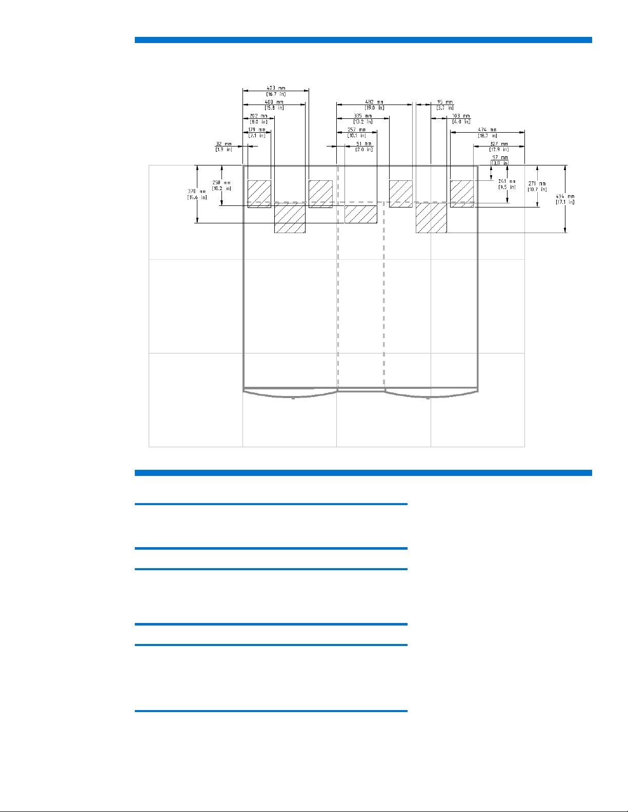
Figure 28: Recommended floor cutouts (dual rack configuration)—Option 1 (Left rack side flush to tile)
Note:
The wider opening in the back of the IT rack is optional.
Note:
The floor tile sizes used in Figure 28 are 600 mm x 600 mm (23.6 inches x
23.6 inches). Floor tile sizes vary.
Note:
The allowable tolerances are +/- 3.2 mm (+/- 0.125 inches). When
installing multiple MCS 5042 units in a row, you must consider the
tolerances as you plan the cutouts.
39
Page 40

Figure 29: Recommended floor cutouts (dual rack configuration)—Option 2 (Right rack side flush to tile)
Note:
The wider opening in the back of the IT rack is optional.
Note:
The floor tile sizes used in Figure 29 are 600 mm x 600 mm (23.6 inches x
23.6 inches). Floor tile sizes vary.
Note:
The allowable tolerances are +/- 3.2 mm (+/- 0.125 inches). When
installing multiple MCS 5042 units in a row, you must consider the
tolerances as you plan the cutouts.
40
Page 41
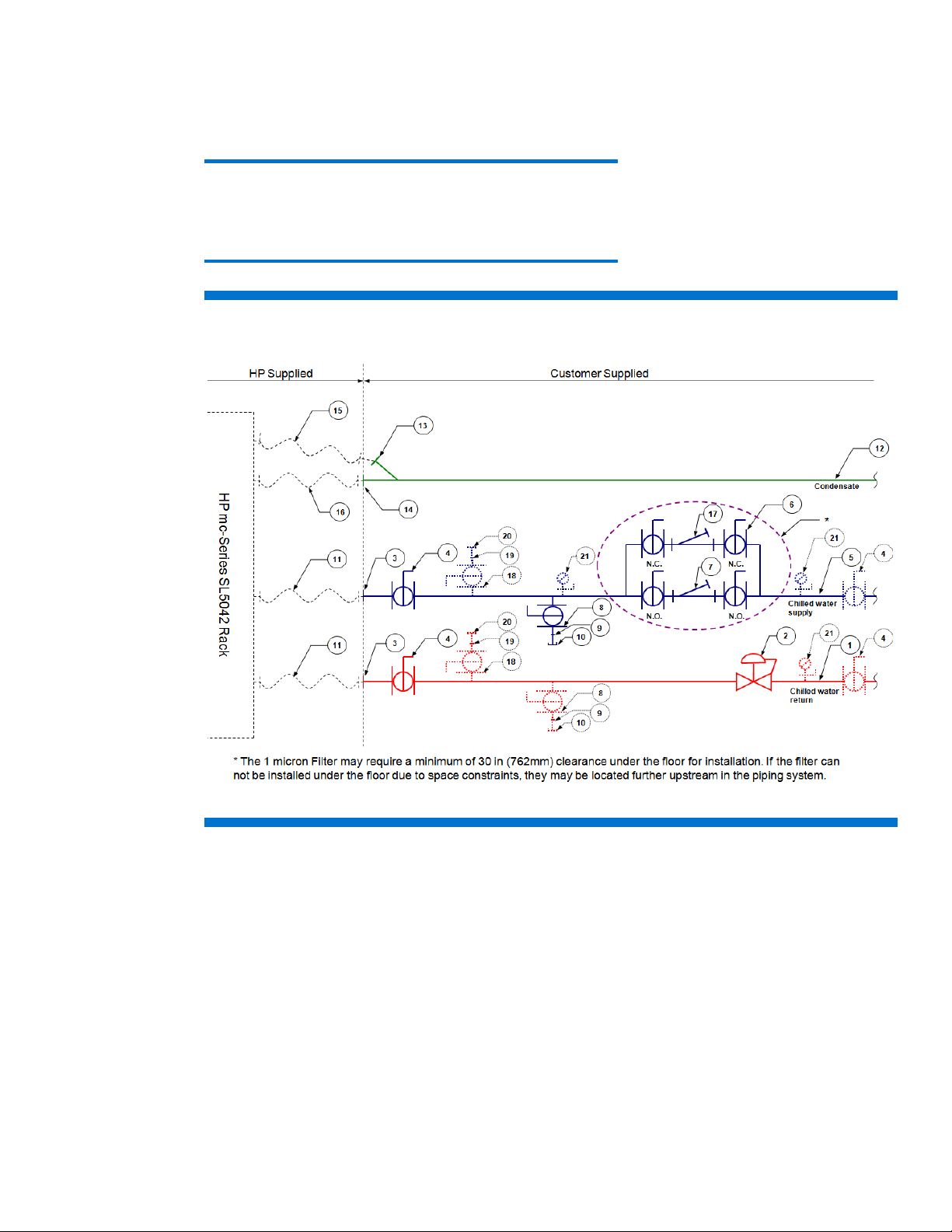
Chilled water system components
The chilled water supply and return service to each MCS 5042 is required to have a particular
combination of components for optimal performance. These components are identified in Figure 30
and described in Table 7.
Note:
Components in Figure 30 drawn with a solid line are strongly
recommended. Components drawn with dot lines are advisable for a
higher availability and serviceability.
Figure 30: Recommended plumbing configuration for the MCS 5042
41
Page 42

Table 7: Typical plumbing components for a MCS SL4042 configuration
Item Description Specifications
1 Chilled water return
line
Pipe:31.75 mm(1.25 inch), ASTM B 88, Type L, hard-drawn copper
Fittings: ASTM B16.22 Wrought copper
Solder: ASTM B 32, 95-5 Tin Antimony
Thread Sealant: Seal and assemble according to local materials and practices
2 Flow/measurement
balancing valve
Valve type: 31.75 mm (1.25 inch) bronze balancing valve, ball design, with positive
shutoff, integral checked metering ports, adjustable knob, memory device, calibrated
nameplate, integral drain port, and solder end connections
Position: horizontal run of pipe.
Note: Orient drain port toward MCS 5042. Avoid fittings closer to measurement
valve than five (5) pipe diameters upstream and two (2) pipe diameters downstream
for maximum performance.
®
CSM-61 or equivalent, typical 1.
Watts
3 Pipe 31.75 mm (1.25 inch) copper, male (NPT or BSPP) adapter to connect the MCS
5042 water hoses, typical 2
4 Isolation valves Valve type: 31.75 mm (1.25 inch) two-piece, full-port, brass ball valve, with chrome
plated brass ball, PTFE seats, steel handle, with Female connections and 31.75 mm
(1.25 inch) bushing on the end toward MCS 5042 hoses.
Pressure rating: 600psi WOG, 150psi WSP.
®
Watts
FBV-3C or equivalent.
5 Chilled water
supply line
Pipe: 31.75 mm (1.25 inch), ASTM B 88, Type L, hard-drawn copper
Fittings: ASTM B16.22 Wrought copper
Solder: ASTM B 32, 95-5 Tin Antimony
Thread Sealant: Seal and assemble according to local materials and practices
6 Strainer isolation
valves
Valve type: 31.75 mm (1.25 inch) two-piece, full-port, brass ball valve, with chrome
plated brass ball, PTFE seats, steel handle, with solder end connections.
Pressure rating: 600psi WOG, 150psi WSP.
Orientation: Stem vertical up for lateral level operation. Offset valves on CHWS and
CHWR piping to prevent interference from lever actuators when closed.
®
FBVS-3C or equivalent
Watts
typical 4
7 Strainer Type: 31.75 (1.25 inch) wye-patterned bronze strainer, with #30 stainless steel wire
mesh liner, ¾-inch tapped retainer cap & gasket, and solder end connections. Provide
19.05 mm (0.75 inch) ball valve for blowdown with cap and chain.
Pressure rating: 400 psi WOG, 125psi WSP.
Orientation: with basket and blowdown valve directed down.
®
S777 or equivalent
Watts
42
8 System drain valve Type: 19.05 mm (0.75 inch) two-piece, full-port, brass ball valve with chrome plated
brass ball, PTFE seats, and steel handle, with threaded connections.
Pressure rating: 600psi WOG, 150psi WSP.
®
FBV-3C or equivalent
Watts
9 Nipple Type: 19.05 mm (0.75 inch) brass close nipple.
10 Cap Type: 19.05 mm (0.75 inch) brass cap with chain.
11 Hose Type: 1.25-inch flexible hose supplied with HP mc-Series 5042 Water Hook-up Kit.
12 Condensate line Pipe: 19.05 mm (0.75 inch) copper or Schedule 40 PVC
Fittings: Wrought Copper or Schedule 40 PVC
Orientation: Sloping downward in a minimum angle of 1º (0.25 inch per 1 ft) and
away from the MCS 5042 for gravity drain
13 Compression fitting Type: 6.35 mm (0.25 inch) male NPT X 8 mm (0.31 inch) compression fitting, Parker
Page 43

Item Description Specifications
Hannifin, FBMB8-1/4 Metrulok fitting, Festo QB-1/4-5/16-U or equivalent and
installed by plumbing contractor, typical 1.
14 Hose barb Type: 12.7 mm (0.50 inch) I.D. hose barb x ¾-inch male NPT, Parker Hannifin,
125HBL-8-12, fitting or equivalent and installed by plumbing contractor, typical 1.
15 Hose Type: 8 mm (0.31 inch) outer-diameter (O.D.) flexible hose supplied with MCS 5042.
16 Hose Type: 9 mm (0.35 inch) inner diameter flexible hose supplied with MCS 5042.
17 Filter 1μm filter is recommended for optimal long-term performance of the MCS 5042. A
cartridge or bag filter could be used in a full flow or side stream flow configuration.
®
FM4X2 stainless steel housing or equivalent. Provide dielectric unions on both
Watts
connections. Provide pleated cartridge rated for 1 μm. Depending on water quality,
multiple units in parallel might be required.
18 Manual air vent Type: 19.05 mm (0.75 inch) two-piece, full-port, brass ball valve with chrome plated
brass ball, PTFE seats, and steel handle, with threaded connections.
Pressure rating: 600psi WOG, 150psi WSP.
®
FBV-3C or equivalent
Watts
19 Nipple Type: 19.05 mm (0.75 inch_ brass close nipple.
20 Cap Type: 19.05 mm (0.75 inch) brass cap with chain.
21 Test plug Type: Corrosion-resistant brass body with core inserts, gasketed and threaded cap,
with extended stem for units to suit piping insulation thickness.
®
Watts
TP or equivalent.
Typical plumbing installation guidelines
• Installation service for this MCS 5042 is order number UE005E.
• Contractors shall install all valves, strainers, and other piping components to the specifications
provided in the Chapter 2 section “Piping approaches.” All components shall be readily accessible.
• Contractor shall flush all lines of debris and cap prior to MCS 5042 installation.
• Contractors shall furnish and install Armacell AP/Armaflex® closed-cell elastomeric thermal
insulation with minimum 25 mm (1 inch) minimum wall thickness on all customer piping and fittings.
Contractors shall furnish and install similar insulation type with minimum 6.4 mm (0.25 inch) wall
thickness for MCS 5042 chilled water hoses and fittings. The MCS 5042 hoses have a 45 mm
(1.75 inch) outer diameter and a bolt clamp that is 76 mm (3 inches) wide, 57 mm (2.25inches)
high and 51 mm (2 inches) deep on the side that must be connected to the infrastructure pipe. All
insulation joints shall be taped with AP/Armaflex® Insulation Tape, 3 mm (1/8 inch) thick x 50 mm
(2 inches) wide x 9.1 m (30 feet) long. Mitered fittings must be cemented with Armaflex® 520
Adhesive.
• HP MCS 5042 condensate and overflow hoses do not require insulation.
• Filters might require a minimum of 762 mm (30 inches) clearance under the floor for installation. If
the filters cannot be installed under the floor due to space constraints, they can be placed upstream
of the piping system.
Caution:
The water supply system feeding the MCS 5042 must capable of
withstanding the following situations:
– Deadheading (operating with a closed line)
– Operation with rapid and frequent changes in flow requirements
– Operation over long periods of time with zero water flow.
43
Page 44

Note:
HP recommends that the HP mc-Series 5042 Hook Up Kit (BW971A) be
ordered for each MCS 5042 to be installed.
Coolant requirements
General thermal requirements
Table 8: Facility coolant requirements
Parameter Value
Allowable operational chilled water temperature 1
Minimum
Maximum
Maximum heat load (50kW) operational chilled water temperature 1
Minimum
Maximum
Chilled water flow rate (maximum) 1 Approximately 159 lpm (42 gpm)
Inlet/outlet water connections to MCS 5042 (2) 2 1.75-inch BSPP (parallel-thread)
Inlet/outlet hose connections to facility 1.25-inch BSPP (parallel-thread)
Hose insulation thickness 6.3 mm (0.25 inch), min. closed cell
Condensate discharge tubing 3 m (118 inch) length,
Overflow tubing 3 m (118 in) length,
Chilled water pressure differential at required flow 1 - 1.5 bar (15 – 22 psi) required 3
Cooling capacity 1 50 kW Maximum
1
For more information, see “Determining heat load capacities.”
2
For more information, see “Plumbing considerations.”
3
For more information, see “Determining heat load capacities.”
18°C (64°F) Max
13°C (55°F) Max
8 mm (0.31 inch) outer diameter,
6 mm (0.24 inch) inner diameter
15 mm (0.59 inch) outer diameter,
9 mm (0.35 inch) inner diameter
(Performance is affected by water
See Figures 21, 32, and 33.)
7°C (45°F) Min.
7°C (45°F) Min.
temperature—
In addition to the requirements listed in Table 8, the coolant must meet the requirements listed “Water
quality requirements.”
44
Caution:
Operating the MCS 5042 below the allowable chilled water temperature
should be avoided, because it might cause excessive amount of
condensation.
Important:
The MCS 5042 must not be operated with being supplied of a public water
system, like drinking water. Only systems that are operating by recycling
water to cool the MCS 5042 are highly recommended for proper use.
Page 45
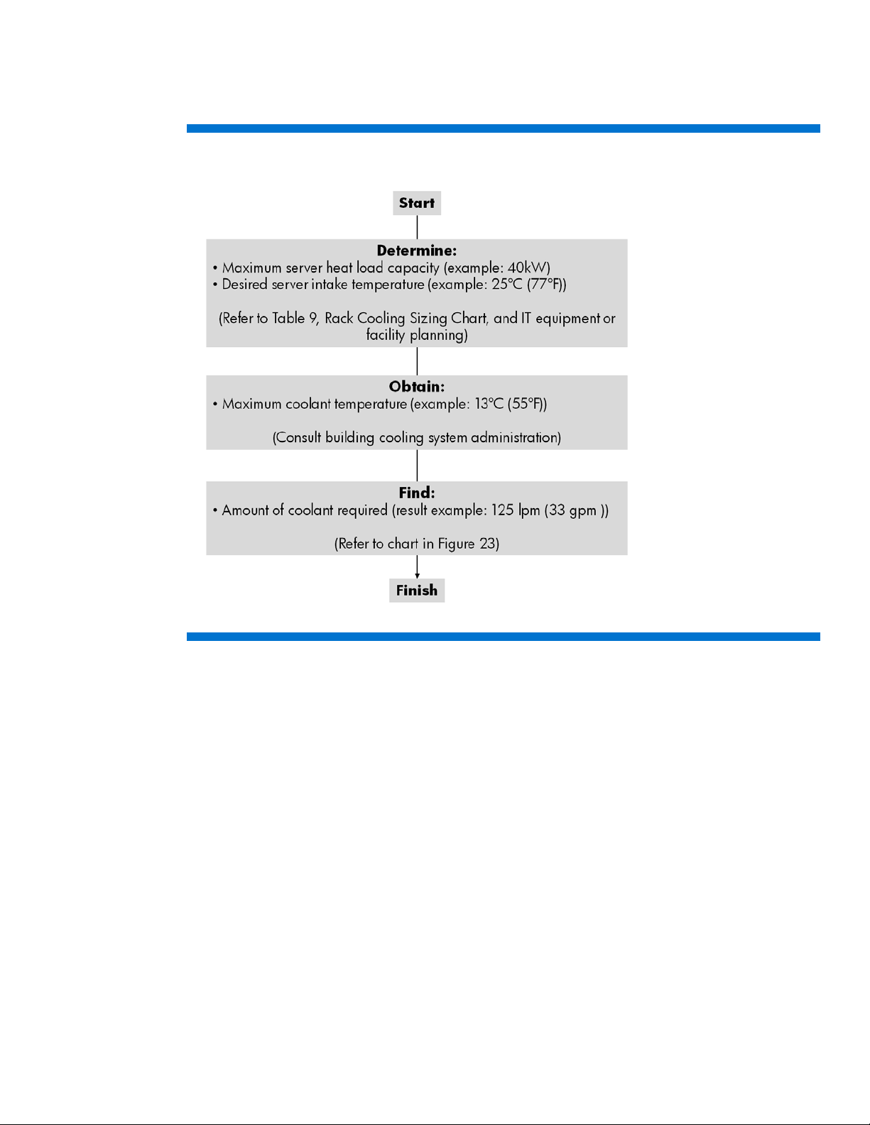
You must perform several steps to determine the coolant requirements and corresponding resources
necessary for effective implementation of the MCS 5042. The flowchart in Figure 31 outlines the steps
and necessary information/resources for each aspect of the implementation.
Figure 31: Coolant implementation flow chart for one rack
Cooling loop sizing
Sizing the cooling loops can be straight forward based on the planned cooling requirements of each
populated/planned MCS 5042 server enclosure. The amount (watts) of heat to be removed from each
component in the server rack must be added together for the total heat to be removed by the MCS
5042 cabinet. You can copy Table 9 for documenting individual cabinet calculations. Calculations
must include the equipment installed today and additional equipment planned for installation over the
design life of the system.
45
Page 46

Table 9: Rack Cooling Loop Sizing Chart
Total for Cabinet 1
Installed
Component
Component 1:
Component 2:
Component 3:
Component 4:
Component 5:
Component 6:
Component 7:
Component 8:
Component 9:
Component 10:
1
An approximate value can be estimated by assuming all power entering the cabinet is converted to heat.
Quantity
Max. Watts
Generated
Max. CFM
Required
Max. Watts
Total
Max. CFM
Total
After calculating the total expected required heat load, use the charts in “Determining heat load
capacities” to determine required water flow and pressure based on potential chilled water
temperatures. The pressure (PSID) must be measured prior to the cold water inlet/after warm water
outlet. All water system equipment, materials, and installation must comply with any applicable
construction codes and LAHJ.
46
Page 47

Determining heat load capacities
The total airflow required by the equipment installed in each server rack must be compared with the
total available supply from the MCS 5042, so it is not exceeded. The fans in the MCS 5042 are
speed controlled to reduce the airflow in case the maximum cooling capacity is not demanded from
the MCS 5042. Table 10 provides a few examples of the approximate fan speeds by the demanded
cooling capacity from the MCS 5042.
Table 10: Approximate fan step at certain cooling capacity
Approximate cooling capacity Approximate fan speed
~9 kW 40–45%
~16 kW 60–70%
~24 kW 75–85%
~32 kW 90–100%
>40 kW 100%
A minimum heat load is necessary for operating the MCS 5042 properly. This minimum depends on
the water supply temperature as shown in Table 11.
Table 11: Minimum heat load at different water supply temperatures and server air intake temperature
Server air intake temperature Water supply temperature Minimum heat load
7ºC (45°F) 9 kW
20°C (68ºF)
25°C (77ºF)
Note:
When the minimum heat load is not provided to the MCS 5042, it can
cause unstable control of the temperatures and flow rates of the MCS
5042.
10ºC (50°F) 7 kW
13ºC (55°F) 6 kW
16ºC (61°F) 6 kW
7–13°C (45–55°F) 16 kW
16ºC (61°F) 14 kW
18ºC (64°F) 10 kW
Consult with your HP representative for further information.
The charts in Figures 32 and 33 offer a guideline for determining the approximate amount of heat
that can be removed from MCS 5042 based on 20°C (68°F) and 25° C (77°F) server intake air
temperatures (in degrees Celsius) and flow rates (liters per minute (lpm) or in US gallons per minute
(gpm)) being delivered to the unit.
Note:
The term “water” in the following charts refers to the coolant described in
“Water quality requirements
” section.
47
Page 48

Figure 32: MCS 5042 coolant flow requirements with 20°C (68°F) server intake air
48
Page 49

Figure 33: MCS 5042 coolant flow requirements with 25°C (77°F) server intake air
The following pressure drop chart in Figure 33 is provided as a reference indicating water flow versus
the water pressure for a fully-opened MCS 5042 water control valve.
49
Page 50

Figure 34: Flow rate versus delta pressure (water control valve fully open)
A minimum water pressure difference of 1.0 to 1.5 bar (15 to 20 psi) between facility supply and
return is required. Figure 34 gives the pressure difference with a fully opened control valve. In
operation the control valve is maintaining the water flow to the MCS 5042 by introducing pressure
resistance to reduce the flow to accommodate different water temperatures and cooling capacity. This
way the pressure loss in operation appears higher than shown in Figure 34. But to have the full scale
of water flow available, the provided system pressure difference must be slightly higher than the
maximum pressure loss with a fully opened control valve.
50
Page 51

Water quality requirements
osed-loop water must not contain any lime scale deposits or loose debris. The water must have a
Cl
low level of hardness, particularly a low level of carbon hardness. Filters must be used to remove free
floating particulates and regularly maintained. Additionally, the water must not be so soft that it
corrodes the materials that it comes into contact. You must periodically add new fresh water, but also
you to remove some of the enriched water. HP recommends a #30 mesh filter for filtering water fed to
the MCS 5042 and a 1 μm filter for prolonged performance.
Note:
If water quality specifications are out of range, consult a water quality
expert.
Table 12: Water quality ranges required for continuous quality of performance for the MCS 5042 liquid cooling system
Parameter Range (See above note)
pH 7 to 9
Specific Conductance, at 25° C, μmhos <2500
Sulfur, Total, as SO4, ppm <100
Chloride, as Cl, ppm <50
Sulfide, as S, ppm <10
Hardness, Total, as CaCO3, ppm <200
Iron, Total, as Fe, ppm <3.0
Manganese, Total, as Mn, ppm <0.1
Bacteria, CFUs/ml
Residue on evaporation, ppm <500
Turbidity, NTU 20
Corrosion inhibitor Recommended
Caution:
Contaminated water might cause decreased cooling capacity or disruption
in service. The water flowing into the MCS 5042 unit must meet the
guidelines stated in the HP mc-Series 5042 Rack Site Preparation Guide.
Damage caused by contaminated water is not covered by the MCS unit
warranty.
Note:
HP recommends that particulate filtration be implemented into the
dedicated water supply system feeding each MCS 5042.
<1000
51
Page 52

Another consideration for water is the required set point. Temperatures near or below 0°C (32°F)
indicate that the chilled water plant condenser is very close to or below the freezing point of the
water. (The minimum chilled water temperature to be supplied to the MCS 5042 is 7°C or 45°F.) This
temperature might cause a blockage and damage to the unit, so an additive like glycol might be
necessary to lower the freezing point. However the heat transfer potential of the water is lower,
therefore, you must consider proper equipment capacity derating.
In a cooling loop, metallic materials in a pipe distribution network are in constant contact with recirculating liquid and can react with impurities to cause corrosion that can develop into leaks or form
deposits that can develop into blockages.
The rate of galvanic corrosion depends on the electrical potential between the two dissimilar metals
and the temperature of the liquid.
Note:
A 10°C (50°F) rise in water temperature can double the rate of corrosion.
Additional water precautions
The following actions must be taken during the installation of the MCS 5042:
• Ensure that all foreign matter and particulates are flushed from the system prior to installing the
water kit for the MCS 5042.
• Evaluate the short- and long-term system requirements, versus available water capacity.
• Ensure your chilled water loop is properly designed for liquid cooling systems, separate from the
sanitary water systems within your building (such as, bathroom, sink, or drinking water).
• Make sure facility managers are aware of the additional load being added to the building chilled
water supply. Be aware that the heat load being added might have an effect on other components
being cooled by the chilled water plant.
Caution:
The water supply system feeding the MCS 5042 must be capable of
withstanding deadheading (operating with a closed line) and operation
with rapid and frequent changes in flow requirements, including long
periods of time with zero water flow.
Plumbing materials to avoid
The following materials must not be used with a closed water system:
• Oxidizing biocides
• Aluminum components
• High zinc/brass components
• Non-stainless steel iron components
52
Page 53

Environmental considerations
Table 13: Recommended environmental specifications
Parameter Value
Room Temperature
Recommended Minimum/Maximum
Allowable Minimum/Maximum
Humidity:
Recommended Minimum
Recommended Maximum
Allowable range
Note:
The temperatures stated are for an elevation of 0 to 5000 feet above sea
level. The maximum operating temperatures must be de-rated by 1ºC per
1000 feet for locations 5000 to 10,000 feet above sea level.
18°C (64.4°F)/27°C (80.6°F)
15°C (59°F)/32°C (90°F)
5.5°C (41.9°F) dew point
60% relative humidity and 15°C (59°F) dew point
20%–-80%
Control system
The MCS 5042 includes a control system that constantly monitors the air temperatures, water
temperatures, and flow rate. The management module attempts to maintain the air temperature at the
target set point. If the set point temperature cannot be maintained, the MCS 5042 management
module will generate an alarm and notify facility management systems as configured.
Note:
For site evaluations and technical consulting services for your site, see the
HP mc-Series 5042 User Guide.
Before installing and running active components
Prior to starting up any active components (servers, storage devices, and so on) mounted in the MCS
5042, the following steps must be performed:
1. Ensure that the chilled water source is on and flowing prior to the start-up of an MCS 5042.
2. Ensure that the MCS 5042 is fully operational and running before turning on the servers and
closing the front and rear cabinet doors.
Caution:
If the MCS 5042 is left running in manual mode for a period of time
without an adequate heat load being generated by servers or other
computing and networking devices, excess condensation might occur within
the cabinet or system.
For more information on the installation of the MCS 5042, see the MCS 5042 documentation on the
HP website (
contentType=SupportManual&lang=en&cc=us&docIndexId=64179&taskId=101&prodTypeId=34475
89&prodSeriesId=3657806).
http://h20000.www2.hp.com/bizsupport/TechSupport/DocumentIndex.jsp?
53
Page 54

Appendix A Forms and checklists
Delivery survey form
The delivery survey form (Figure 35) lists delivery or installation requirements. If any of the items on
the list apply, enter the appropriate information in the areas provided on the form. Special instructions
or recommendations must be entered on the special instructions or recommendations form. The
following list gives examples of special instructions or issues:
• Packaging restrictions at the facility, such as size and weight limitations
• Special delivery procedures
• Special equipment required for installation, such as tracking or hoists
• What time the facility is available for installation (after the equipment is unloaded)
• Special security requirements applicable to the facility, such as security clearance
Figure 35: Delivery Survey Form
Warning:
To prevent possible serious personal injury or damage to equipment, do not
move the MCS 5042 up or down stairs.
54
Page 55

Pre-installation checklists
Site preparation checklist
Table 14 is a site preparation checklist. For each item, check Yes or No in the appropriate column. If
answering No, include a comment and the date. A No answer means that an alternative might be
required.
Table 14: Site preparation checklist
Area/
Item
Facility considerations
1 Is there a completed floor plan, including a detailed location of the MCS 5042
2 Is there adequate space for maintenance needs? HP recommends a clearance at a
3 Is access to the site or computer room restricted?
4 Is the computer room structurally complete? Expected date of completion?
5 Is a raised floor installed and in good condition?
6 Is the raised floor system, including needed cutouts, able to adequately support the
7 Are there channels or cutouts for cable routing?
8 Is there a network line available?
9 Is a telephone line available?
10 Are floor tiles in good condition and properly braced?
11 Is there a leak detector for the chilled water system?
Power and lighting considerations
condition Yes No
relative to the floor tile breaks and supports?
minimum of 1219 mm (48 inches) for the front and a minimum of 914 mm (36
inches) minimum at the rear.
fully loaded rack and MCS?
(external to the MCS 5042)
Comment/
Date
12 Are there AC outlets available for servicing needs? (for example, laptop)
13 Does the input voltage correspond to MCS 5042 specifications?
14 Is dual source power used? If so, identify types and evaluate grounding.
15 Does the input frequency correspond to equipment specifications?
16 Is power conditioning equipment installed?
17 Is there a dedicated branch circuit for equipment?
18 Is the dedicated branch circuit less than 22.86 m (75 feet) away?
19 Are the input circuit breakers sized to protect their respective receptacles
for equipment loads?
Safety considerations
20 Is there an emergency power shutoff switch?
21 Is there a telephone available for emergency purposes?
22 Is there a fire protection system in the computer room?
23 Is antistatic flooring installed?
55
Page 56

Area/
Item
Cooling considerations
condition Yes No
Comment/
Date
24 Can the room temperature be maintained between the
recommended 18°C (64.4 °F) Min. –27°C (80.6 °F) Max.
and allowable 15°C (59 °F) Min. –32°C (90 °F) Max.
(up to 5000 ft) Derate 1°C/1000 ft
above 5000 ft and up to 10,000 ft
25 Can humidity level be maintained at the recommended level of
5.5°C (41.9°F) dew point to 60% relative humidity and 15°C (59°F) dew point, with an allowable
humidity levels of 20% to 80%
26 Are air-conditioning filters installed/clean?
Water preparation considerations
27 Has the water been tested for acceptable quality for use in the
MCS 5042?
28 If the water quality is unacceptable, have adequate treatment and
filtration measures been put into place?
29 Have the water temperature and flow been evaluated?
30 If temperature and flow are not adequate, have supplemental chiller units
and water pumps been implemented to achieve ample performance?
31 Has an adequately sized water-to-water heat exchanger been implemented
to provide a dedicated water loop to the MCS 5042?
32 Has piping of an appropriate diameter, material, and pressure tolerance
been installed to reach the back of each MCS 5042?
33 Is there a provision for fluid collected from the condensation and overflow
hoses at each MCS 5042?
56
Page 57

Appendix B: Conversion factors and formulas
The conversion factors provided in this appendix are intended to ease data calculation for systems
that do not provide information in the format requested in this Site Preparation Guide. The following
list includes the conversion factors used in this document, as well as additional conversion factors that
might be helpful in determining those factors required for site planning.
Conversion factors for refrigeration
• 1 watt = 0.86 kcal/hour
• 1 watt = 3.412 British thermal unit (Btu)/hour
• 1 ton = 200 Btu/minute
• 1 ton = 12,000 Btu/hour
• 1 ton = 3,517.2 W
Metric equivalents
• 1 centimeter = 0.3937 inch
• 1 meter = 3.28 feet
• 1 meter = 1.09 yards
• 1 inch = 2.54 centimeter
• 1 feet = 0.305 meter
3
• 1 cubic feet/minute (CFM) = 1.7m
/hour
kVA conversions
• Three phase kiloVolt-Amps (kVA) = V × A × �
• Singl
e phase kVA = V × A⁄1000
Formulas
• kVA = [Voltage x Current (amps)]/1000
• Watts = VA x power factor (PF)
• Btu = Watts x 3.41
√3⁄1000
57
Page 58

Glossary
Table 15: Terms and abbreviations
Term Description
Apparent power A value of power for AC circuits that is calculated as the product of RMS current
times RMS voltage, without taking the power factor into account.
ASL Above sea level
Btu/hr British thermal units per hour. The amount of heat required to raise one pound of
water 1°F/hr, a common measure of heat transfer rate.
CFM Cubic feet per minute, commonly used to measure the rate of air flow in an
air-conditioning system.
Chilled water system A type of air-conditioning system that has no refrigerant in the unit itself. The
refrigerant is contained in a chiller, which is located remotely. The chiller cools
water, which is piped to the air conditioner or HP Modular Cooling System to
cool the space.
Derate To lower the rated capability of an electrical or mechanical apparatus.
Heat exchanger Cooling unit that maintains two separate environments inside and outside of the
cabinet or room. It can be water-to-water, water-to-air, or air-to-air configurations,
in either direction.
Inrush current The peak current flowing into a power supply the instant AC power is applied.
This peak is usually much higher than the typical input current because of the
charging of the input filter capacitors. When switching power supplies are first
turned on, they present high initial currents as a result of filter capacitor
impedance. These large filter capacitors act like a short circuit, producing an
immediate inrush surge current with a fast rise time. The peak inrush current can
be several orders of magnitude greater than the supply’s typical current.
Leakage current A term relating to current flowing between the AC supply wires and earth ground.
The term does not necessarily denote a fault condition. In power supplies,
leakage current usually refers to the 60-Hz current, which flows through the EMI
filter capacitors that are connected between the AC lines and ground.
Maximum input current The operating current of the product equal to the maximum load divided by the
minimum input voltage.
Power factor The ratio of true power (watts) to apparent power (VA) in an AC circuit. In power
conversion technology, power factor is used in conjunction with describing the
AC input current to the power supply.
RMS Root-mean-square. Term that refers to the most common mathematical method of
defining the effective voltage or current of an AC wave. To determine RMS value,
three mathematical operations are carried out on the function representing the AC
waveform:
(1) The square of the waveform function (usually a sine wave) is determined.
(2) The function resulting from step 1 is averaged over time.
(3) The square root of the function resulting from step 2 is found.
Theoretical maximum power
consumption
True power In an AC circuit, true power is the actual power consumed and is measured in
Maximum wattage of a given configuration, assuming worst-case conditions
(thermal tolerances, workloads, and so forth) on all system components. It is
extremely unlikely that any customer will experience this level of power
consumption.
watts. It is distinguished from apparent power by eliminating the reactive power
component that might be present
58
Typical input current The operating current of the product measured using a typical load and target
voltage.
Page 59

Term Description
Typical power consumption Represents the expected power consumption of a given configuration. The typical
value is the approximate power consumption that a customer will most likely
experience and can use for power budgeting purposes.
Watt A standard unit of power defined as one Joule of energy transferred or dissipated
in one second.
59
Page 60

Technology for better business outcomes
© Copyright 2012 Hewlett
contained herein is subject to change without notice. The only warranties for HP
products and services are set forth in the express warranty statements
accompanying such products and services. Nothing herein should
constituting an additional warranty. HP shall not be liable for technical or editorial
errors or omissions contained herein.
4AA2
Legal notices
The information in this document is subject to change without notice.
HP makes no warranty of any kind with regard to this manual, including, but not limited to, the
implied warranties of merchantability and fitness for a particular purpose. HP shall not be held liable
for errors contained herein or direct, indirect, special, incidental or consequential damages in
connection with the furnishing, performance, or use of this material.
Watts Regulator Company is a subsidiary of Watts Water Technologies, Inc. (Watts).
©Armacell Enterprise GmbH.
Restricted rights legend
Use, duplication or disclosure by the U.S. Government is subject to restrictions as set forth in
subparagraph (c) (1) (ii) of the Rights in Technical Data and Computer Software clause at DFARS
252.227-70 1 3 for DOD agencies, and subparagraphs (c) (1) and (c) (2) of the Commercial
Computer Software Restricted Rights clause at FAR 52.227-1 9 for other agencies.
HEWLETT-PACKARD COMPANY, 3000 Hanover Street, Palo Alto, California 94304 U.S.A.
For more information
HP Infrastructure products website:
http://h18000.www1.hp.com/products/servers/platforms/rackandpower.html
-6422ENW, 3rd revision, December 2012
-Packard Development Company, L.P. The information
be construed as
 Loading...