

Page 1

HP Modular Cooling System 200/100
200/100.
Site Preparation Guide
Abstract
This document provides site preparation guidance for the MCS-
Part Number: 749810-001
June 2014
Edition: 1
Page 2

© Copyright 2014 Hewlett-Packard Development Company, L.P.
The information contained herein is subject to change without notice. The only warranties for HP products and services are set forth in the express
warranty statements accompanying such products and services. Nothing herein should be construed as constituting an additional warranty. HP shall
not be liable for technical or editorial errors or omissions contained herein.
Restricted rights legend
Use, duplication or disclosure by the U.S. Government is subject to restrictions as set forth in subparagraph (c) (1) (ii) of the Rights in Technical Data
and Computer Software clause at DFARS 252.227-70 1 3 for DOD agencies, and subparagraphs (c) (1) and (c) (2) of the Commercial Computer
Software Restricted Rights clause at FAR 52.227-1 9 for other agencies.
HEWLETT-PACKARD COMPANY, Palo Alto, CA 94304-1185, USA
HEWLETT-PACKARD COMPANY, HQ-TRE, 71004 Boeblingen, Germany
Page 3

Contents
Overview ..................................................................................................................................... 5
Overview .................................................................................................................................................... 5
Product overview .......................................................................................................................................... 8
Key components ......................................................................................................................................... 12
MCS-100 components ...................................................................................................................... 13
MCS-200 components ...................................................................................................................... 15
Physical specifications ................................................................................................................................ 17
Electrical specifications ............................................................................................................................... 18
Facility planning for implementation .............................................................................................. 20
Facility planning overview ........................................................................................................................... 20
Space and positioning considerations .......................................................................................................... 20
Delivery space requirements .............................................................................................................. 21
Maneuvering space requirements ....................................................................................................... 21
Operational space requirements ........................................................................................................ 23
System positioning ........................................................................................................................... 25
Cable openings ............................................................................................................................... 26
Cabinet leveling feet ......................................................................................................................... 29
Floor loading considerations ............................................................................................................. 37
Electrical considerations .............................................................................................................................. 40
System grounding ............................................................................................................................ 41
Voltage fluctuations and outages ....................................................................................................... 43
Electrical planning around water-handling components ........................................................................ 43
Connecting to facility A/C power ...................................................................................................... 43
Coolant source planning ............................................................................................................................. 45
Plumbing considerations ................................................................................................................... 46
Piping approaches ........................................................................................................................... 51
Hose openings ................................................................................................................................. 52
Raised floor cutouts for the MCS unit .................................................................................................. 55
Chilled water system components ....................................................................................................... 67
Typical plumbing installation guidelines .............................................................................................. 70
Coolant requirements .................................................................................................................................. 71
General thermal requirements ............................................................................................................ 71
Cooling loop sizing .......................................................................................................................... 72
Determining heat load capacities ....................................................................................................... 72
Acceptable water quality specifications .............................................................................................. 78
Additional water precautions ............................................................................................................. 78
Plumbing materials to avoid .............................................................................................................. 79
Environmental considerations ...................................................................................................................... 79
Control system ........................................................................................................................................... 79
Before installing and running active components ................................................................................. 79
Appendix A: Forms and checklists ................................................................................................ 81
Delivery survey form ................................................................................................................................... 81
Pre-installation checklists ............................................................................................................................. 82
Site preparation checklist .................................................................................................................. 82
Contents 3
Page 4

Appendix B: Conversion factors and formulas ................................................................................ 85
Conversion factors and formulas .................................................................................................................. 85
Conversion factors for refrigeration .................................................................................................... 85
Metric equivalents ............................................................................................................................ 85
kVa conversions ............................................................................................................................... 85
Formulas ......................................................................................................................................... 85
Regulatory information ................................................................................................................ 86
Safety and regulatory compliance ................................................................................................................ 86
Turkey RoHS material content declaration ..................................................................................................... 86
Ukraine RoHS material content declaration ................................................................................................... 86
Warranty information ................................................................................................................................. 86
Regulatory requirements for EXIT signs .......................................................................................................... 86
Support and other resources ........................................................................................................ 88
Before you contact HP ................................................................................................................................ 88
HP contact information ................................................................................................................................ 88
Acronyms and abbreviations ........................................................................................................ 89
Documentation feedback ............................................................................................................. 91
Index ......................................................................................................................................... 92
Contents 4
Page 5
Overview
Overview
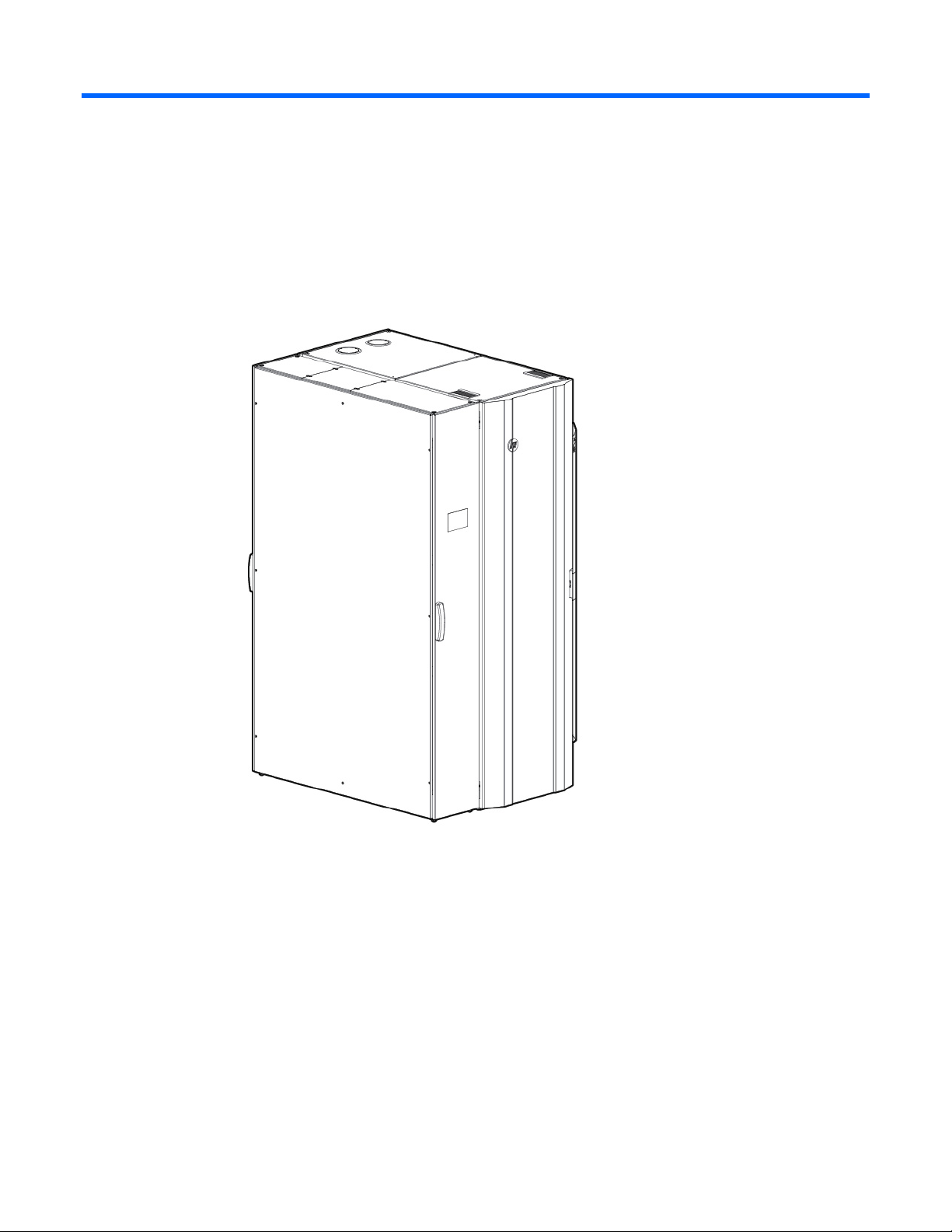
The MCS-200/100 is a supplemental cooling system for data centers. It is offered in four configurations:
• MCS-100 unit (single-rack configuration)
Overview 5
Page 6
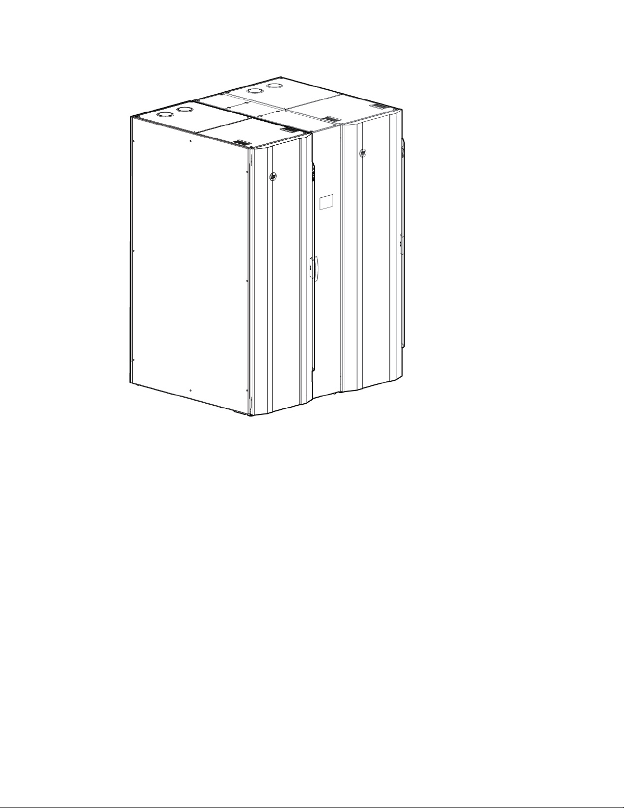
• MCS-100 unit (dual-rack configuration)
Overview 6
Page 7

• MCS-200 unit (single-rack configuration)
Overview 7
Page 8

• MCS-200 unit (dual-rack configuration)
For successful site preparation, consider the following information:
• To provide dedicated cooling for servers and other IT equipment, the MCS-200/100 integrates with the
facility chilled water plant or a dedicated chilled water loop. HP recommends that you install a
dedicated cooling loop to the MCS-200/100.
• The system provides cooling, recirculation, and condensation management, and it requires a small
amount of AC electric power.
• Internal monitoring and control sensors assure server inlet air set points to be achieved and provide
constant performance feedback through local and network interfaces.
Product overview
The MCS-200/100 is a modular, distributed cooling solution that removes the high levels of heat generated
by current advanced server and mass storage systems. The MCS-200/100 provides a uniform, effective,
affordable, and distributed cooling approach for servers and other IT equipment installed in server racks. The
MCS-200/100 is a closed-loop cooling system integrated as part of a non-ventilated server enclosure, in
contrast to a conventional ”open” server enclosure with perforated front and rear doors.
Overview 8
Page 9

Air flow for MCS-100 (single-rack configuration)
Overview 9
Page 10

Air flow for MCS-100 (dual-rack configuration)
Overview 10
Page 11

Air flow for MCS-200 (single-rack configuration)
Overview 11
Page 12

Air flow for MCS-200 (dual-rack configuration)
The special horizontal airflow of the MCS-200/100 fully supports the industry standard front-to-back cooling
principle, such as cold air drawing into the front of the server and warm air being expelled out the rear of the
unit. All devices receive adequate and evenly distributed cool air regardless of the mounting position within
the enclosure. The MCS-200/100 distributes precisely cooled and targeted air flow evenly across the front
of the IT equipment. Warmed air is then channeled from the rear of the IT equipment into the side-mounted
or center-mounted MCS-200/100 cooling unit. From there it is cooled and recirculated to the front of the
equipment stack.
Key components
The MCS-200/100 uses the following key components to provide cooling performance. Some of these
components are optional for MCS-100. For more information, see "MCS-100 components (on page 13)."
• Main breakers—Provide power for the MCS-200/100 through circuit breakers. They do not control
power at the input panel.
If the MCS-200/100 is still connected to a power source, voltage is applied before the circuit breakers
at the input panel
• Heat Exchanger Module (HEX)—Uses an air-to-water heat transfer device specially created for
demanding data center environments
• Display—Provides general cooling unit status
• Management module—Provides users with web-based capabilities to set, monitor, and control
temperature within the modular cooling unit, and displays the health of the unit
Overview 12
Page 13

• Fan controller—Operates the fans, according to the cabinet air temperature
• Air bleeder valve—Enables air to manually bleed out of the system when coolant is initially filled
• Water controller—Senses condensation, leaks, water temperatures, flow rate, and the status of the
water valve, and sends this data to the management module
• AC input/network connection—Provides primary and secondary AC input connections, if available,
and a network management interface
• AC transfer switch—Provides dual-AC power with a fail-over feature for redundancy
• Fans—Provide circulation of cooled air through the computer equipment rack
• Water group—Includes the water valve, flow meter, check valve, and temperature sensors
A condensation pump with overflow and condensation lines connects to the water group.
Each MCS-200/100 has one water group.
MCS-100 components
The MCS-100 is an air and water heat exchanger that removes high levels of excess heat generated by
equipment installed in HP racks. The installed equipment pulls cold air in through the front of the closed
MCS-100 and uses that air for internal cooling. After the air is warmed, the MCS-100 expels the air through
the rear vents.
Overview 13
Page 14

3
Item Description
1
2
4
5
6
Control valve
Flow meter
Humidity sensor
Heat exchanger unit
Fan units (1 fan by default, 4 fans maximum)
Management module
HP provides several components to complement or complete your MCS-100. For more information, see the
HP Modular Cooling System 200/100 Options Installation Guide.
The following illustrations show the MCS-100 optional components.
Unit side view
Item Reference
1
2
3
4
5
6
Condensation pump (optional)
Condensation pump controller (optional)
Control valve
Flow meter
Humidity sensor
Rear extension (optional)
Overview 14
Page 15

Item Reference
9
7
8
10
Heat exchanger unit
TFT touchscreen display (optional)
Fan units (1 fan by default, 4 fans maximum)
Management module
Unit top view
For easier viewing, the canopies are not shown in this illustration.
Item Reference
1
2
3
4
Water module
Fan module
AC power distribution unit (AC transfer switch optional)
Emergency door opening (optional)
MCS-200 components
The MCS-200 is an air and water heat exchanger that removes high levels of excess heat generated by
equipment installed in HP racks. The installed equipment pulls cold air in through the front of the closed
MCS-200 and uses the air for internal cooling. After the air is warmed, the MCS-200 expels the air through
the rear vents.
HP provides several components to complement or complete your MCS-200. For more information, see the
HP Modular Cooling System 200/100 Options Installation Guide.
Overview 15
Page 16

The following illustrations show the MCS-200 optional components.
1
6
Unit side view
Item Reference
Condensation pump
2
3
4
5
Condensation pump controller
Control valve
Flow meter
Humidity sensor
Rear extension
7
8
9
10
Heat exchanger unit
TFT touchscreen display
Fan units (4 fans by default, 6 fans maximum)
Management module
Unit top view
Overview 16
Page 17

For easier viewing, the canopies are not shown in this illustration.
Item Reference
1
2
3
4
5
Water module
Fan module
Condensation pump transformer 277v (optional)
AC transfer switch
Emergency door opening
Physical specifications
The following table lists the approximate physical specifications of a single MCS-100 or MCS-200 as
received from the factory.
MCS-100 (single rack configuration) physical specifications
Parameter
Height
Width
Depth
Weight
Packaged system (as
shipped on pallet)
2285 mm (90 inches) 2007 mm (79 inches) 2007 mm (79 inches)
1219 mm (48 inches) 904 mm (35.6 inches) 904 mm (35.6 inches)
1829 mm (72 inches) 1311 mm (51.6 inches) 1311 mm (51.6 inches)
670 kg (1479 lb)
Unpackaged system
Unpackaged CTO system
(off pallet, unwrapped)
1
417 kg (919 lb)2 1324 kg (2919 lb)3
MCS-100 expansion rack physical specifications
Overview 17
Page 18

Weight
Depth
Parameter
Height
Width
Depth
Packaged system (as
shipped on pallet)
Unpackaged system
(off pallet, unwrapped)
2159 mm (85 inches) 2007 mm (79 inches) 2007 mm (79 inches)
914.4 mm (36 inches) 600 mm (23.6 inches) 600 mm (23.6 inches)
1727 mm (68 inches) 1200 mm (47.2 inches) 1200 mm (47.2 inches)
Unpackaged CTO system
265 kg (584 lb)1 135 kg (299 lb)2 1042 kg (2297 lb)3
MCS-200 (single rack configuration) physical specifications
Parameter
Height
Width
Packaged system (as
shipped on pallet)
Unpackaged system
(off pallet, unwrapped)
2285 mm (90 inches) 2007 mm (79 inches) 2007 mm (79 inches)
1219 mm (48 inches) 904 mm (35.6 inches) 904 mm (35.6 inches)
Unpackaged CTO system
1829 mm (72 inches) 1510 mm (59.5 inches) 1510 mm (59.5 inches)
Weight
MCS-200 expansion rack physical specifications
Parameter
732 kg (1614 lb)
Packaged system (as
shipped on pallet)
Height
Width
Depth
Weight
2159 mm (85 inches) 2007 mm (79 inches) 2007 mm (79 inches)
914.4 mm (36 inches) 600 mm (23.6 inches) 600 mm (23.6 inches)
1727 mm (68 inches) 1399 mm (55.1 inches) 1399 mm (55.1 inches)
308 kg (680 lb)
1
478 kg (1054 lb)2 1521 kg (3353 lb)3
Unpackaged system
Unpackaged CTO system
(off pallet, unwrapped)
1
179 kg (395 lb)2 1222 kg (2694 lb)3
1 Weight for a completely packaged system with unpopulated server rack
2 Weight for an unpackaged system with unpopulated server rack
3 Approximate weight for an unpackaged CTO system (actual weight varies, according to configuration)
If the top shipping bracket interferes with deploying the MCS-200/100, it can be removed. With the top
shipping bracket, the total height of the unpackaged system is 2069 mm (81.5 inches).
Electrical specifications
The following table lists the electrical specifications for the MCS-100 unit.
Parameter Value Comments
Operating voltage
AC line phase
Maximum input current
Maximum inrush current
Dropout/hold-up time at
minimum line voltage
Transfer time of AC transfer
switch
Circuit breaker rating
Power factor
Ground leakage current
230 VAC +/- 10%, 50 Hz
208 VAC +/- 10%, 60 Hz
Single —
18 A Per line cord
200 A Per line cord
20 ms —
2 s —
LAHJ Per cord
> 0.95 At all loads
< 19.4 mA Per line cord
—
Overview 18
Page 19

Parameter Value Comments
Ground leakage current
Power cord
230 V, 16 A
208 V, 18 A
The following table lists the electrical specifications for the MCS-200 unit.
IEC 309-to-Procon 700105
NEMA L6-20-to-Procon 700105
Parameter Value Comments
Operating voltage
AC line phase
Maximum input current
Maximum inrush current
Dropout/hold-up time at
minimum line voltage
Transfer time of AC transfer
switch
Circuit breaker rating
Power factor
Power cords
230 VAC +/- 10%, 50 Hz,
277 VAC +/- 10%, 60 Hz,
and 208 VAC +/- 10%, 60 Hz
Single —
18 A Per line cord
200 A Per line cord
20 ms —
2 s —
LAHJ Per cord
> 0.95 At all loads
< 19.4 mA Per line cord
230 V, 16 A
208 V, 18 A
—
IEC 309-to-Procon 700105 (Qty 2)
NEMA L6-20-to-Procon 700105
Overview 19
Page 20

Facility planning for implementation
Facility planning overview
The MCS-200/100 offers an incremental data center cooling solution, capable of cooling 30 kW of heat
with the MCS-100 unit or 50 kW of heat with the MCS-200 unit.
In planning water supply and design, take into consideration short and long-term needs for cooling.
Immediate supply needs must meet the specifications and target cooling requirements, based on the
parameters defined in this site preparation guide. In anticipation of future heat loads, design and install
dedicated loop chilled water piping, based on specific cooling load increments (such as 50 kW or 250 kW),
the specific number of MCS-200/100 per row or loop, and other site build-out planning parameters. As
cooling, rack space, and equipment density requirements increase, you can add MCS-200/100 units to the
chilled water system.
To route water lines to your MCS-200/100 unit, use one of the following methods:
• Through an opening in the raised floor
• Lying on top of the floor (for MCS-200 only)
• Through the top of the MCS-200/100 unit
For more information on routing the water lines, see the Hook Up Kit installation instructions in the HP
Modular Cooling System 200/100 Options Installation Guide.
Installation service for the MCS-200/100 is order number UE005E.
For site evaluations and technical consulting for your site, see the HP Services website
(http://www.hp.com/services/criticalfacilities).
The implementation of the MCS-200/100 aligns with Data Center Best Practices. For more information, see
Optimizing Data Centers for High-Density Computing, which can be found on the HP website
(http://h18004.www1.hp.com/products/servers/proliantstorage/racks/10000series/documentation.ht
ml).
This section discusses key issues for site preparedness, including:
• Space considerations for delivery, operation, and service, and other space-related considerations such
as floor loading
• Electrical considerations
• Coolant source options and quality considerations
• Other considerations
A complete site preparation checklist is provided in Appendix A: Forms and checklists (on page 81).
Space and positioning considerations
When fully populated, the MCS-200/100 unit is larger and heavier than a standard 482.6 mm (19-inch)
equipment rack. Therefore, more space is required to maneuver, operate, and service the MCS-200/100.
Facility planning for implementation 20
 Loading...