

Page 1
LaserJet Enterprise MFP M630
Troubleshooting Manual
M630h
M630zM630fM630dn
www.hp.com/support/ljMFPM630
For product repair and part number
information, see the Repair Manual.
Page 2

Page 3

HP LaserJet Enterprise M630
Troubleshooting Manual
Page 4

Copyright and License
© 2014 Copyright Hewlett-Packard
Development Company, L.P.
Reproduction, adaptation, or translation
without prior written permission is prohibited,
except as allowed under the copyright laws.
The information contained herein is subject to
change without notice.
The only warranties for HP products and
services are set forth in the express warranty
statements accompanying such products and
services. Nothing herein should be construed
as constituting an additional warranty. HP shall
not be liable for technical or editorial errors or
omissions contained herein.
Edition 1, 9/2014
Page 5

Conventions used in this guide
TIP: Helpful hints or shortcuts.
Reinstallation tip: Reinstallation helpful hints, shortcuts, or considerations.
NOTE: Information that explains a concept or how to complete a task.
IMPORTANT: Information that help the user to avoid potential product error conditions.
CAUTION: Procedures that the user must follow to avoid losing data or damaging the product.
WARNING! Procedures that the user must follow to avoid personal injury, catastrophic loss of data, or
extensive damage to the product.
ENWW iii
Page 6

iv Conventions used in this guide ENWW
Page 7

Table of contents
1 Theory of operation ....................................................................................................................................... 1
Basic operation ...................................................................................................................................................... 2
Sequence of operation (product) ........................................................................................................ 4
Sequence of operation (scanner) ........................................................................................................ 5
Formatter-control system ..................................................................................................................................... 6
Formatter hardware ............................................................................................................................ 6
Sleep mode ....................................................................................................................... 6
Input/output (I/O) ............................................................................................................. 8
CPU .................................................................................................................................... 8
Memory ............................................................................................................................. 8
Random access memory (RAM) ...................................................................... 8
Firmware ........................................................................................................................... 8
Nonvolatile random access memory (NVRAM) ................................................................. 8
Image Resolution Enhancement technology ................................................................... 8
HP Memory Enhancement technology ............................................................................. 9
Printer job language (PJL) ................................................................................................. 9
Printer management language (PML) .............................................................................. 9
Control panel ....................................................................................................................................... 9
Scanner interface ................................................................................................................................ 9
Engine-control system ........................................................................................................................................ 10
DC controller ...................................................................................................................................... 11
Motors ............................................................................................................................. 12
Fans ................................................................................................................................. 13
High-voltage power supply ............................................................................................ 14
Low-voltage power supply ............................................................................................. 15
Overcurrent/overvoltage protection ........................................................... 16
Voltage detection ......................................................................................... 16
Safety ............................................................................................................ 16
Sleep (power save) mode ............................................................................. 17
Low-voltage power supply functions .......................................................... 17
Fuser control ................................................................................................................... 18
Fuser temperature control ........................................................................... 19
ENWW v
Page 8

Fuser sleeve temperature protection .......................................................... 20
Fuser failure detection ................................................................................. 20
Pressure roller cleaning ............................................................................... 21
Ambient-temperature detection ................................................................. 21
Laser/scanner system ......................................................................................................................................... 22
Laser/scanner failure ........................................................................................................................ 23
Safety ................................................................................................................................................ 23
Image-formation system .................................................................................................................................... 24
Electrophotographic process ............................................................................................................ 26
Step 1: Primary charge (conditioning) ............................................................................ 27
Step 2: Laser-beam exposure (writing) .......................................................................... 27
Step 3: Developing .......................................................................................................... 28
Step 4: Transfer .............................................................................................................. 28
Step 5: Separation .......................................................................................................... 29
Step 6: Fusing .................................................................................................................. 29
Step 7: Drum cleaning ..................................................................................................... 30
Toner cartridge .................................................................................................................................. 31
Memory chip .................................................................................................................... 31
Cartridge presence and life detection ............................................................................ 31
Pickup, feed, and delivery system ...................................................................................................................... 33
Pickup-and-feed block ...................................................................................................................... 38
Tray 2 pickup ................................................................................................................... 39
Tray 2 paper-size detection and tray-present detection ............................ 40
Tray 1 pickup ................................................................................................................... 43
Tray 1 paper-presence detection ................................................................. 44
Feed speed control ......................................................................................................... 44
Skew-feed prevention .................................................................................................... 45
Paper-length detection .................................................................................................. 46
Paper-width detection .................................................................................................... 46
Fusing, reverse, and delivery block .................................................................................................. 47
Fusing .............................................................................................................................. 47
Pressure roller pressurization and depressurization control ....................................... 48
Reverse and delivery control .......................................................................................... 49
Face-down delivery ...................................................................................... 50
Face-up delivery ........................................................................................... 51
Output bin paper-full detection ................................................................... 52
Duplex block ...................................................................................................................................... 53
Duplex side registration adjustment operation ............................................................. 53
Jam detection .................................................................................................................................... 55
Optional paper feeders ........................................................................................................................................ 59
Paper-feeder pickup and feed components ..................................................................................... 62
vi ENWW
Page 9

1x500-sheet paper feeder signal flow and component locations ................................ 62
1x500-sheet paper feeder with cabinet signal flow and component locations ........... 63
2,500-sheet high-capacity paper feeder signal flow and component locations .......... 65
Paper-size detection and tray-presence detection ......................................................................... 67
Paper feeder tray lift operation ........................................................................................................ 68
Trays 3 and 4 lift operation ............................................................................................ 68
Tray 5 lift operation ........................................................................................................ 69
Paper feeder jam detection .............................................................................................................. 70
Scanning/image capture system ........................................................................................................................ 73
Scanner .............................................................................................................................................. 73
Document feed system ..................................................................................................................... 73
Sensors in the document feeder .................................................................................... 73
Document feeder paper path ......................................................................................... 75
Document feeder simplex operation ............................................................................. 75
Document feeder e-duplex operation ............................................................................ 76
Front-side and back-side background selector ............................................................. 77
Deskew operation ........................................................................................................... 78
Document feeder hinges ................................................................................................ 79
Stapling mailbox .................................................................................................................................................. 81
Motor control ..................................................................................................................................... 83
Failure detection ............................................................................................................. 84
Delivery operation .......................................................................................................... 84
Staple operation ........................................................................................... 86
Stapler .......................................................................................................... 91
Output bin 3 lift operation ........................................................................... 92
Stacker mode .................................................................................................................................... 93
Mailbox/job separator mode ............................................................................................................ 93
Jam detection .................................................................................................................................... 94
Automatic delivery ............................................................................................................................ 96
2 Solve problems ........................................................................................................................................... 97
Solve problems checklist ..................................................................................................................................... 98
Menu map .......................................................................................................................................................... 101
Current settings pages ...................................................................................................................................... 101
Event log ............................................................................................................................................................ 101
Pre-boot menu options ..................................................................................................................................... 103
Remote Admin ................................................................................................................................. 110
Required software and network connection ................................................................ 110
Telnet client ................................................................................................ 111
Network connection ................................................................................... 112
Connect a remote connection ...................................................................................... 112
ENWW vii
Page 10

Disconnect a remote connection .................................................................................. 117
Troubleshooting process .................................................................................................................................. 119
Determine the problem source ....................................................................................................... 119
Troubleshooting flowchart .......................................................................................... 119
Power subsystem ............................................................................................................................ 120
Power-on checks .......................................................................................................... 120
Power-on troubleshooting overview ......................................................... 120
Scanning subsystem ....................................................................................................................... 124
Control panel checks ....................................................................................................................... 124
Control panel diagnostic flowcharts ............................................................................ 127
Touchscreen black, white, or dim (no image) ............................................ 128
Touchscreen is slow to respond or requires multiple presses to
respond ....................................................................................................... 129
Touchscreen has an unresponsive zone .................................................... 130
No control panel sound .............................................................................. 131
Home button is unresponsive .................................................................... 132
Hardware integration pocket (HIP) is not functioning (control panel
functional) .................................................................................................. 133
Tools for troubleshooting ................................................................................................................................. 134
Individual component diagnostics .................................................................................................. 134
LED diagnostics ............................................................................................................. 134
Understand lights on the formatter .......................................................... 134
Engine diagnostics ........................................................................................................ 139
Defeating interlocks ................................................................................... 139
Disable cartridge check .............................................................................. 140
Engine test button ...................................................................................... 140
Paper path test ............................................................................................................. 141
Paper path sensors test ............................................................................................... 141
Manual sensor tests and tray/bin sensor tests ........................................................... 143
Manual sensor tests ................................................................................... 143
Tray/bin manual sensor test ...................................................................... 148
Print/stop test .............................................................................................................. 150
Component tests .......................................................................................................... 150
Component test (special-mode test) ......................................................... 150
Scanner tests ................................................................................................................ 153
Scanner tests .............................................................................................. 153
Diagrams ......................................................................................................................................... 155
Block diagrams ............................................................................................................. 155
Sensors ....................................................................................................... 155
Switches (product base) ............................................................................. 159
Solenoids (product base) ........................................................................... 160
viii ENWW
Page 11

Clutch (product base) ................................................................................. 161
Motors ......................................................................................................... 162
Fans (product base) .................................................................................... 166
Main assemblies ......................................................................................... 167
Main PCAs (product base) ........................................................................... 174
Rollers (product base) ................................................................................ 175
DC controller connections ............................................................................................ 176
Scanner controller board (SBC) connectors ................................................................. 178
1x500-sheet feeder, 1x500-sheet feeder with cabinet, and 2,500-sheet high-
capacity feeder connectors .......................................................................................... 179
Stapling mailbox connectors ........................................................................................ 180
General timing chart ..................................................................................................... 182
General circuit diagrams ............................................................................................... 184
Internal print-quality test pages .................................................................................................... 189
Print quality troubleshooting pages ............................................................................ 189
Fuser test page ............................................................................................................. 192
Cleaning page ............................................................................................................... 193
Enable and configure auto cleaning .......................................................... 193
Print configuration page ............................................................................................... 194
Configuration page ..................................................................................... 194
HP embedded Jetdirect page ..................................................................... 196
Finding important information on the configuration pages ..................... 197
Print quality troubleshooting tools ................................................................................................ 198
Print quality troubleshooting tools: repetitive defects ruler ...................................... 198
Control-panel menus ...................................................................................................................... 199
Administration menu .................................................................................................... 199
Reports menu ............................................................................................. 199
General Settings menu ............................................................................... 201
Copy Settings menu ................................................................................... 206
Scan/Digital Send Settings menu .............................................................. 214
Fax Settings menu (fax models only) ........................................................ 224
General Print Settings menu ...................................................................... 234
Default Print Options menu ....................................................................... 237
Display Settings menu ............................................................................... 239
Manage Supplies menu .............................................................................. 241
Manage Trays menu ................................................................................... 244
Network Settings menu ............................................................................. 246
Troubleshooting menu ............................................................................... 257
Device Maintenance menu ............................................................................................ 259
Backup/Restore menu ............................................................................... 259
Calibration/Cleaning menu ........................................................................ 260
ENWW ix
Page 12

USB Firmware Upgrade menu .................................................................... 262
Service menu .............................................................................................. 262
Control panel message document (CPMD) ..................................................................................... 263
Control-panel message types ...................................................................................... 263
Control-panel messages and event log entries ........................................................... 263
10.XX.YZ Error Messages ........................................................................... 263
11.XX.YZ Error Messages ........................................................................... 266
13.XX.YZ Error Messages ........................................................................... 267
13.XX.YZ Error Messages ........................................................................... 293
30.XX.YZ Error Messages ........................................................................... 293
31.XX.YZ Error Messages ........................................................................... 300
32.XX.YX and 33.XX.YZ Error Messages .................................................... 306
40.XX.YZ Error Messages ........................................................................... 312
41.XX.YZ Error Messages ........................................................................... 314
42.XX.YZ Error Messages ........................................................................... 321
44.XX.XX Error Messages ........................................................................... 321
47.XX.XX Error Messages ........................................................................... 323
48.XX.YY Error Messages ........................................................................... 325
49.XX.YY Error Messages ........................................................................... 326
50.WX.YZ Error Messages .......................................................................... 326
51.XX.YZ, 52.XX.YZ Error Messages .......................................................... 328
54.XX.YZ Error Messages ........................................................................... 329
55.XX.YZ, 56.XX.YZ Error Messages .......................................................... 330
57.XX.YZ Error Messages ........................................................................... 331
58.XX.YZ Error Messages ........................................................................... 333
59.XX.YZ Error Messages ........................................................................... 335
60.00.0Y, 62.00.00 Error Messages .......................................................... 337
65.X0.AZ Error Messages ........................................................................... 339
66.WX.YZ Error Messages .......................................................................... 339
70.XX.YY Error Messages ........................................................................... 343
80.XX.YY, 82.XX.YY Error Messages .......................................................... 343
98.0X.0Y Error Messages ........................................................................... 344
99.XX.YY Error Messages ........................................................................... 345
Alpha Error Messages ................................................................................. 352
Control panel: event log messages ................................................................................................ 386
Print or view an event log ............................................................................................. 387
Clear the event log ........................................................................................................ 387
Clear jams .......................................................................................................................................................... 388
Jam sensor locations ...................................................................................................................... 388
Paper path sensor locations ......................................................................................... 388
Jam locations .................................................................................................................................. 392
x ENWW
Page 13

Auto-navigation for clearing jams .................................................................................................. 392
Experiencing frequent or recurring paper jams? ............................................................................ 392
Clear jams in the document feeder ................................................................................................. 394
Clear jams in Tray 1 ......................................................................................................................... 398
Clear jams in Tray 2, 3, or 4 ............................................................................................................. 401
Clear jams in the 1,500-sheet high-capacity input tray (Tray 5) ................................................... 403
Clear jams in the right door ............................................................................................................. 406
Clear jams in the lower-right door .................................................................................................. 407
Clear jams in the duplexer and fuser .............................................................................................. 408
Clear jams under the top cover and in the registration area ......................................................... 413
Clear jams in the output bin ............................................................................................................ 416
Clear jams in the stapling mailbox accessory ................................................................................ 417
Clear staple jams in the stapling mailbox accessory ..................................................................... 419
Change jam recovery ....................................................................................................................... 423
Paper feeds incorrectly or becomes jammed ................................................................................................... 424
The product does not pick up paper ............................................................................................... 424
The product picks up multiple sheets of paper .............................................................................. 424
The document feeder jams, skews, or picks up multiple sheets of paper .................................... 425
Prevent paper jams ......................................................................................................................... 425
Use manual print modes ................................................................................................................................... 426
Solve image quality problems .......................................................................................................................... 429
Image defects table ........................................................................................................................ 429
Clean the product .............................................................................................................................................. 439
Print a cleaning page ...................................................................................................................... 439
Check the scanner glass for dirt or smudges ................................................................................. 440
Clean the pickup rollers and separation pad in the document feeder ........................................... 442
Clean the pickup, feed, and separation rollers in the 1x500-sheet paper-feeder and 1x500-
sheet paper-feeder with storage cabinet ...................................................................................... 444
Clean the pickup, feed, and separation rollers in the 2,500-sheet high-capacity feeder (HCI) .... 445
Solve performance problems ............................................................................................................................ 446
Solve connectivity problems ............................................................................................................................. 447
Solve USB connection problems ..................................................................................................... 447
Solve wired network problems ....................................................................................................... 447
Poor physical connection ............................................................................................. 447
The computer is using the incorrect IP address for the product ................................. 447
The computer is unable to communicate with the product ........................................ 448
The product is using incorrect link and duplex settings for the network ................... 448
New software programs might be causing compatibility problems ........................... 448
The computer or workstation might be set up incorrectly .......................................... 448
The product is disabled, or other network settings are incorrect ............................... 448
Service mode functions ..................................................................................................................................... 449
ENWW xi
Page 14

Service menu ................................................................................................................................... 449
Product resets ................................................................................................................................. 452
Restore factory-set defaults ........................................................................................ 452
Restore the service ID ................................................................................................... 453
Product cold reset ........................................................................................................ 453
Format Disk and Partial Clean functions ........................................................................................ 454
Active and repository firmware locations .................................................................... 454
Partial Clean .................................................................................................................. 454
Execute a Partial Clean ............................................................................... 455
Format Disk ................................................................................................................... 455
Execute a Format Disk ................................................................................ 456
Solve fax problems ............................................................................................................................................ 457
Checklist for solving fax problems ................................................................................................. 457
What type of phone line are you using? ....................................................................... 457
Are you using a surge-protection device? .................................................................... 457
Are you using a phone company voice-messaging service or an answering
machine? ....................................................................................................................... 457
Does your phone line have a call-waiting feature? ..................................................... 457
Check fax accessory status .......................................................................................... 458
General fax problems ...................................................................................................................... 459
The fax failed to send ................................................................................................... 459
An Out of Memory status message displays on the product control panel ................ 459
Print quality of a photo is poor or prints as a gray box ............................................... 459
You touched the Stop button to cancel a fax, but the fax was still sent ..................... 459
No fax address book button displays ........................................................................... 459
Not able to locate the Fax settings in HP Web Jetadmin ............................................. 459
The header is appended to the top of the page when the overlay option is enabled 459
A mix of names and numbers is in the recipients box ................................................. 459
A one-page fax prints as two pages ............................................................................. 460
A document stops in the document feeder in the middle of faxing ............................ 460
The volume for sounds coming from the fax accessory is too high or too low .......... 460
Use Fax over VoIP networks ........................................................................................................... 460
Problems with receiving faxes ........................................................................................................ 461
Problems with sending faxes ......................................................................................................... 463
Fax error messages on the product control panel ......................................................................... 464
Send-fax messages ...................................................................................................... 465
Receive-fax messages .................................................................................................. 466
Service settings ............................................................................................................................... 467
Settings in the Troubleshooting menu ........................................................................ 467
Firmware upgrades ........................................................................................................................................... 468
Determine the installed revision of firmware ................................................................................ 469
xii ENWW
Page 15

Perform a firmware upgrade .......................................................................................................... 470
HP Embedded Web Server ............................................................................................ 470
USB flash drive (Pre-boot menu) ................................................................................. 470
USB flash drive (control-panel menu) .......................................................................... 471
Appendix A Product specifications ................................................................................................................. 473
Product dimensions ........................................................................................................................................... 474
Product space requirements ............................................................................................................................. 475
Power consumption, electrical specifications, and acoustic emissions .......................................................... 476
Environmental specifications ............................................................................................................................ 476
Certificate of Volatility ...................................................................................................................................... 477
Index ........................................................................................................................................................... 479
ENWW xiii
Page 16

xiv ENWW
Page 17

List of tables
Table 1-1 Sequence of operation (product) ......................................................................................................................... 4
Table 1-2 Sequence of operation (scanner) ......................................................................................................................... 5
Table 1-3 Formatter hardware components ....................................................................................................................... 6
Table 1-4 Motors ................................................................................................................................................................ 12
Table 1-5 Fans .................................................................................................................................................................... 13
Table 1-6 Converted DC voltages ....................................................................................................................................... 16
Table 1-7 Low-voltage power supply functions ................................................................................................................ 17
Table 1-8 Fuser components ............................................................................................................................................. 18
Table 1-9 Sensors ............................................................................................................................................................... 34
Table 1-10 Motors, clutch, and solenoids .......................................................................................................................... 35
Table 1-11 Switches ........................................................................................................................................................... 36
Table 1-12 Tray 2 media-size detection switch components ........................................................................................... 40
Table 1-13 Feed speed control ........................................................................................................................................... 44
Table 1-14 Paper-width detection ..................................................................................................................................... 46
Table 1-15 Jams that the product detects ......................................................................................................................... 56
Table 1-16 Pickup and feed components (1x500-sheet paper feeder) ............................................................................ 62
Table 1-17 Pickup and feed components (1x500-sheet paper feeder with cabinet) ....................................................... 64
Table 1-18 Pickup and feed components (2,500-sheet high-capacity paper feeder) ...................................................... 66
Table 1-19 Paper-size detection and tray-presence detection (1 x 500-sheet paper feeder and 1x500-sheet
paper feeder with cabinet) ..................................................................................................................................................... 67
Table 1-20 Paper-size detection and tray-presence detection (2,500-sheet high-capacity paper feeder) ................... 67
Table 1-21 Document feeder sensors ................................................................................................................................ 74
Table 1-22 Document feeder paper path ........................................................................................................................... 75
Table 1-23 Document feeder deskew features ................................................................................................................. 78
Table 1-24 Motor control (stapling mailbox) ..................................................................................................................... 83
Table 1-25 Delivery components (stapling mailbox) ........................................................................................................ 85
Table 2-1 Pre-boot menu options (1 of 7) ....................................................................................................................... 103
Table 2-2 Pre-boot menu options (2 of 7) ....................................................................................................................... 104
Table 2-3 Pre-boot menu options (3 of 7) ....................................................................................................................... 105
Table 2-4 Pre-boot menu options (4 of 7) ....................................................................................................................... 106
Table 2-5 Pre-boot menu options (5 of 7) ....................................................................................................................... 107
Table 2-6 Pre-boot menu options (6 of 7) ....................................................................................................................... 108
ENWW xv
Page 18

Table 2-7 Pre-boot menu options (7 of 7) ....................................................................................................................... 109
Table 2-8 Troubleshooting flowchart .............................................................................................................................. 119
Table 2-9 Control panel diagnostic functions .................................................................................................................. 124
Table 2-10 Connectivity LED, product initialization ........................................................................................................ 135
Table 2-11 Connectivity LED, product operational .......................................................................................................... 137
Table 2-12 Paper-path sensors diagnostic tests ............................................................................................................ 141
Table 2-13 Manual sensor diagnostic tests ..................................................................................................................... 144
Table 2-14 Tray/bin manual sensors ............................................................................................................................... 148
Table 2-15 Component test details ................................................................................................................................. 151
Table 2-16 Sensors (product base) .................................................................................................................................. 155
Table 2-17 Sensors (1x500-sheet paper feeder and 1x500-sheet paper feeder with cabinet) .................................... 156
Table 2-18 Sensors (2,500-sheet high-capacity feeder) (HCI) ........................................................................................ 157
Table 2-19 Sensors (SSMBM) ........................................................................................................................................... 158
Table 2-20 Switches (product base) ................................................................................................................................ 159
Table 2-21 Solenoids (product base) ............................................................................................................................... 160
Table 2-22 Clutch (product base) ..................................................................................................................................... 161
Table 2-23 Motors (product base) ................................................................................................................................... 162
Table 2-24 Motors (1 x 500-sheet paper feeder) ............................................................................................................ 163
Table 2-25 Motors (1x500-sheet and 3 x 500-sheet paper deck) .................................................................................. 163
Table 2-26 Motors (1x500-sheet and 3 x 500-sheet paper deck) .................................................................................. 164
Table 2-27 Motors (SSMBM) ............................................................................................................................................. 165
Table 2-28 Fans (product base) ....................................................................................................................................... 166
Table 2-29 Main assemblies (product base; 1 of 2) ......................................................................................................... 167
Table 2-30 Main assemblies (product base; 2 of 2) ......................................................................................................... 168
Table 2-31 Main assemblies (1 x 500-sheet paper feeder) ............................................................................................. 169
Table 2-32 Main assemblies (1x500-sheet paper feeder with cabinet) ......................................................................... 170
Table 2-33 Main assemblies (2,500-sheet high-capacity feeder) (HCI) .......................................................................... 171
Table 2-34 Main assemblies (SSMBM; 1 of 2) .................................................................................................................. 172
Table 2-35 Main assemblies (SSMBM; 2 of 2) .................................................................................................................. 173
Table 2-36 Main PCAs (product base) .............................................................................................................................. 174
Table 2-37 Rollers (product base) ................................................................................................................................... 175
Table 2-38 DC controller connectors ............................................................................................................................... 176
Table 2-39 Scanner controller board (SCB) connectors .................................................................................................. 178
Table 2-40 1x500-sheet feeder, 1x500-sheet feeder with cabinet, and 2,500-sheet high-capacity feeder
connectors ........................................................................................................................................................................... 179
Table 2-41 Stapling mailbox connectors ......................................................................................................................... 180
Table 2-42 Important information on the configuration pages ...................................................................................... 197
Table 2-43 Reports menu ................................................................................................................................................. 199
Table 2-44 General Settings menu .................................................................................................................................. 201
Table 2-45 Copy Settings menu ....................................................................................................................................... 206
Table 2-46 Scan/Dig
ital Send Settings menu .................................................................................................................. 214
xvi ENWW
Page 19

Table 2-47 Fax Settings menu (fax models only) ............................................................................................................ 224
Table 2-48 General Print Settings menu ......................................................................................................................... 234
Table 2-49 Default Print Options menu ........................................................................................................................... 237
Table 2-50 Display Settings menu ................................................................................................................................... 239
Table 2-51 Manage Supplies menu .................................................................................................................................. 241
Table 2-52 Manage Trays menu ....................................................................................................................................... 244
Table 2-53 Network Settings menu ................................................................................................................................. 246
Table 2-54 Embedded Jetdirect Menu ............................................................................................................................. 246
Table 2-55 Troubleshooting menu .................................................................................................................................. 257
Table 2-56 Backup/Restore menu ................................................................................................................................... 260
Table 2-57 Calibration/Cleaning menu ............................................................................................................................ 260
Table 2-58 Sample event log page .................................................................................................................................. 386
Table 2-59 Sensors (product base) .................................................................................................................................. 388
Table 2-60 1x500-sheet paper-feeder and 1x500-sheet paper-feeder with storage cabinet sensors and
switches
1
.............................................................................................................................................................................. 389
Table 2-61 2,500-sheet high-capacity feeder (HCI) sensors and switches .................................................................... 390
Table 2-62 3-bin stapling mailbox accessory sensors .................................................................................................... 391
1
Table 2-63 Print modes
under the Adjust Paper Types submenu ................................................................................. 427
Table 2-64 Print modes under the Optimize submenu ................................................................................................... 427
Table 2-65 Image defects table ....................................................................................................................................... 429
Table 2-66 Solve performance problems ........................................................................................................................ 446
Table 2-67 Send-fax messages ....................................................................................................................................... 465
Table 2-68 Receive-fax messages ................................................................................................................................... 466
Table A-1 Physical specifications ..................................................................................................................................... 474
Table A-2 Accessory dimensions ...................................................................................................................................... 474
Table A-3 Product space requirements ........................................................................................................................... 475
Table A-4 Operating-environment specifications ........................................................................................................... 476
ENWW xvii
Page 20

xviii ENWW
Page 21

List of figures
Figure 1-1 Relationship between the main product systems .............................................................................................. 2
Figure 1-2 System block diagram ........................................................................................................................................ 3
Figure 1-3 Engine control system block diagram .............................................................................................................. 10
Figure 1-4 DC controller block diagram ............................................................................................................................. 11
Figure 1-5 Motors ............................................................................................................................................................... 12
Figure 1-6 Fans ................................................................................................................................................................... 13
Figure 1-7 High-voltage power supply .............................................................................................................................. 14
Figure 1-8 Low-voltage power supply circuit .................................................................................................................... 15
Figure 1-9 Fuser components ............................................................................................................................................ 18
Figure 1-10 Fuser circuit ..................................................................................................................................................... 19
Figure 1-11 Laser/scanner ................................................................................................................................................. 22
Figure 1-12 Image-formation system components .......................................................................................................... 24
Figure 1-13 Image-formation system motor control ........................................................................................................ 25
Figure 1-14 Stages of image-formation ............................................................................................................................ 26
Figure 1-15 1. Primary charge (conditioning) .................................................................................................................... 27
Figure 1-16 2. Laser-beam exposure (writing) .................................................................................................................. 27
Figure 1-17 3. Developing .................................................................................................................................................. 28
Figure 1-18 4. Transfer ....................................................................................................................................................... 28
Figure 1-19 5. Separation ................................................................................................................................................... 29
Figure 1-20 6. Fusing .......................................................................................................................................................... 29
Figure 1-21 7. Drum cleaning ............................................................................................................................................. 30
Figure 1-22 Toner Cartridge ............................................................................................................................................... 31
Figure 1-23 Pickup, feed, and delivery system .................................................................................................................. 33
Figure 1-24 Sensor locations ............................................................................................................................................. 34
Figure 1-25 Motor, clutch, and solenoid locations ............................................................................................................ 35
Figure 1-26 Switch locations .............................................................................................................................................. 36
Figure 1-27 Pickup-and-feed block ................................................................................................................................... 38
Figure 1-28 Tray 2 pickup ................................................................................................................................................... 39
Figure 1-29 Tray 2 lift operation ........................................................................................................................................ 41
Figure 1-30 Multiple-feed prevention ................................................................................................................................ 42
Figure 1-31 Tray 1 pickup ................................................................................................................................................... 43
Figure 1-32 Skew-feed prevention .................................................................................................................................... 45
ENWW xix
Page 22

Figure 1-33 Fusing, reverse, and delivery block ................................................................................................................ 47
Figure 1-34 Pressure roller pressurization and depressurization control ....................................................................... 48
Figure 1-35 Reverse and delivery control .......................................................................................................................... 49
Figure 1-36 Face-down delivery ........................................................................................................................................ 50
Figure 1-37 Face-up delivery ............................................................................................................................................. 51
Figure 1-38 Output bin paper-full detection ..................................................................................................................... 52
Figure 1-39 Duplex block ................................................................................................................................................... 53
Figure 1-40 Duplex side registration adjustment operation ............................................................................................. 54
Figure 1-41 Jam detection sensors .................................................................................................................................... 56
Figure 1-42 1x500-sheet paper feeder ............................................................................................................................. 59
Figure 1-43 1x500-sheet paper feeder with cabinet ........................................................................................................ 60
Figure 1-44 2,500-sheet high-capacity paper feeder ....................................................................................................... 61
Figure 1-45 Signal flow for the 1x500-sheet paper feeder controller ............................................................................. 62
Figure 1-46 Pickup and feed components (1x500-sheet paper feeder) ........................................................................... 62
Figure 1-47 Signal flow for the 1x500 paper feeder with cabinet controller ................................................................... 63
Figure 1-48 Pickup and feed components (1x500-sheet paper feeder with cabinet) ...................................................... 64
Figure 1-49 Signal flow for the 2,500-sheet high-capacity paper feeder controller ....................................................... 65
Figure 1-50 Pickup and feed components (2,500-sheet high-capacity paper feeder) .................................................... 65
Figure 1-51 Trays 3 and 4 paper feeder lift operation ...................................................................................................... 68
Figure 1-52 Tray 5 paper feeder lift operation .................................................................................................................. 69
Figure 1-53 1x500-sheet paper feeder media feed sensor .............................................................................................. 70
Figure 1-54 1x500-sheet paper feeder with cabinet media feed sensor ......................................................................... 71
Figure 1-55 2,500-sheet high-capacity paper feeder media feed sensors ...................................................................... 72
Figure 1-56 Document feeder sensors .............................................................................................................................. 74
Figure 1-57 Document feeder paper path ......................................................................................................................... 75
Figure 1-58 Document feeder deskew features ................................................................................................................ 78
Figure 1-59 Document feeder open (book mode) ............................................................................................................. 79
Figure 1-60 Document feeder open (60º to 80º) ............................................................................................................... 80
Figure 1-61 Stapling mailbox ............................................................................................................................................. 81
Figure 1-62 Signal flow for the stapling mailbox .............................................................................................................. 82
Figure 1-63 Stapling mailbox motors ................................................................................................................................ 83
Figure 1-64 Delivery components (stapling mailbox) ....................................................................................................... 85
Figure 1-65 Stapling mailbox stapler operation ................................................................................................................ 87
Figure 1-66 Stapling mailbox stapler operation ................................................................................................................ 88
Figure 1-67 Stapling mailbox stapler operation ................................................................................................................ 89
Figure 1-68 Stapling mailbox stapler operation ................................................................................................................ 90
Figure 1-69 Stapling mailbox sensors for the stapler ....................................................................................................... 91
Figure 1-70 Stapling mailbox sensors for output bin 3 lift operation .............................................................................. 92
Figure 1-71 Stapling mailbox sensors for stacker mode .................................................................................................. 93
Figure 1-72 Stapling mailbox sensors for mail
Figure 1-73 Stapling mailbox sensors for jam detection .................................................................................................. 95
box/jam separation ................................................................................. 94
xx ENWW
Page 23

Figure 2-1 Open the Control Panel ................................................................................................................................... 111
Figure 2-2 Turn Windows features on or off .................................................................................................................... 111
Figure 2-3 Enable the telnet client feature ..................................................................................................................... 112
Figure 2-4 Select the +3:Administrator item ................................................................................................................... 113
Figure 2-5 Select the +A:Remote Admin item ................................................................................................................. 113
Figure 2-6 Select the 1:Start Telnet item ........................................................................................................................ 113
Figure 2-7 Telnet connecting message ............................................................................................................................ 113
Figure 2-8 Telnet error message ..................................................................................................................................... 114
Figure 2-9 Telnet server function initialized ................................................................................................................... 114
Figure 2-10 Open a command window ............................................................................................................................ 115
Figure 2-11 Start a telnet session .................................................................................................................................... 115
Figure 2-12 Establish a telnet connection ....................................................................................................................... 115
Figure 2-13 Enter the PIN ................................................................................................................................................. 116
Figure 2-14 Remote Admin window ................................................................................................................................. 116
Figure 2-15 Access the administrator menu ................................................................................................................... 117
Figure 2-16 Access the remote admin menu ................................................................................................................... 117
Figure 2-17 Terminate the telnet connection ................................................................................................................. 118
Figure 2-18 Touchscreen blank, white, or dim (no image) .............................................................................................. 128
Figure 2-19 Touchscreen is slow to respond or requires multiple presses to respond ................................................. 129
Figure 2-20 Touchscreen has an unresponsive zone ...................................................................................................... 130
Figure 2-21 No control panel sound ................................................................................................................................ 131
Figure 2-22 Home button is unresponsive ...................................................................................................................... 132
Figure 2-23 Hardware integration pocket (HIP) is not functioning (control panel functional) ...................................... 133
Figure 2-24 Defeating interlocks ..................................................................................................................................... 139
Figure 2-25 Engine test button ........................................................................................................................................ 140
Figure 2-26 Sensors (product base) ................................................................................................................................. 155
Figure 2-27 Sensors (1x500-sheet paper feeder and 1x500-sheet paper feeder with cabinet) ................................... 156
Figure 2-28 Sensors (2,500-sheet high-capacity feeder) (HCI) ...................................................................................... 157
Figure 2-29 Sensors (SSMBM) .......................................................................................................................................... 158
Figure 2-30 Switches (product base) ............................................................................................................................... 159
Figure 2-31 Solenoids (product base) .............................................................................................................................. 160
Figure 2-32 Clutch (product base) ................................................................................................................................... 161
Figure 2-33 Motors (product base) .................................................................................................................................. 162
Figure 2-34 Motors (1 x 500-sheet paper feeder) ........................................................................................................... 163
Figure 2-35 Motors (1x500-sheet paper feeder) ............................................................................................................ 163
Figure 2-36 Motors (2,500-sheet high-capacity feeder) (HCI) ........................................................................................ 164
Figure 2-37 Motors (SSMBM) ............................................................................................................................................ 165
Figure 2-38 Fans (product base) ...................................................................................................................................... 166
Figure 2-39 Main assemblies (product base; 1 of 2) ....................................................................................................... 167
Figure 2-40 Main assemblies (product base; 2 of 2) ....................................................................................................... 168
Figure 2-41 Main assemblies (1x500-sheet paper feeder) ............................................................................................. 169
ENWW xxi
Page 24

Figure 2-42 Main assemblies (1x 500-sheet paper feeder with cabinet) ....................................................................... 170
Figure 2-43 Main assemblies (2,500-sheet high-capacity feeder) (HCI) ........................................................................ 171
Figure 2-44 Main assemblies (SSMBM; 1 of 2) ................................................................................................................. 172
Figure 2-45 Main assemblies (SSMBM; 2 of 2) ................................................................................................................. 173
Figure 2-46 Main PCAs (product base) ............................................................................................................................. 174
Figure 2-47 Rollers (product base) .................................................................................................................................. 175
Figure 2-48 DC controller PCA connectors ....................................................................................................................... 176
Figure 2-49 Scanner controller board (SCB) connectors ................................................................................................. 178
Figure 2-50 1x500-sheet feeder, 1x500-sheet feeder with cabinet, and 2,500-sheet high-capacity feeder
connectors ........................................................................................................................................................................... 179
Figure 2-51 Stapling mailbox connectors ........................................................................................................................ 180
Figure 2-52 General timing chart (1 of 2) ........................................................................................................................ 182
Figure 2-53 General timing chart (2 of 2) ........................................................................................................................ 183
Figure 2-54 General circuit diagram (product base) (1 of 2) ........................................................................................... 184
Figure 2-55 General circuit diagram (product base) (2 of 2) ........................................................................................... 185
Figure 2-56 General circuit diagram 1x500-sheet feeder, 1x500-sheet feeder with cabinet, and 2,500-sheet
high-capacity feeder (HCI) ................................................................................................................................................... 186
Figure 2-57 General circuit diagram for the stapling mailbox ........................................................................................ 187
Figure 2-58 General circuit diagram for the envelope feeder ......................................................................................... 188
Figure 2-59 Print-quality troubleshooting procedure page ........................................................................................... 190
Figure 2-60 Black print-quality troubleshooting page .................................................................................................... 191
Figure 2-61 Configuration page ....................................................................................................................................... 195
Figure 2-62 HP embedded Jetdirect page ....................................................................................................................... 196
Figure 2-63 Removing paper Stuck in Duplex re-feed path. ........................................................................................... 280
Figure 2-64 Jam detection sensors .................................................................................................................................. 281
Figure 2-65 Opening to the registration assembly ......................................................................................................... 282
Figure 2-66 Paper feed assembly belt ............................................................................................................................. 288
Figure 2-67 Sample event log .......................................................................................................................................... 386
Figure 2-68 Sensors (product base) ................................................................................................................................. 388
Figure 2-69 1x500-sheet paper-feeder and 1x500-sheet paper-feeder with storage cabinet sensors and
switches
1
.............................................................................................................................................................................. 389
Figure 2-70 2,500-sheet high-capacity feeder (HCI) sensors and switches ................................................................... 390
Figure 2-71 Stapling mailbox sensors ............................................................................................................................. 391
Figure A-1 Product space requirements .......................................................................................................................... 475
Figure A-2 Certificate of Volatility 1 of 2) ........................................................................................................................ 477
Figure A-3 Certificate of Volatility (2 of 2) ....................................................................................................................... 478
xxii ENWW
Page 25

1 Theory of operation
●
Basic operation
●
Formatter-control system
●
Engine-control system
●
Laser/scanner system
●
Image-formation system
●
Pickup, feed, and delivery system
●
Optional paper feeders
●
Scanning/image capture system
●
Stapling mailbox
ENWW 1
Page 26
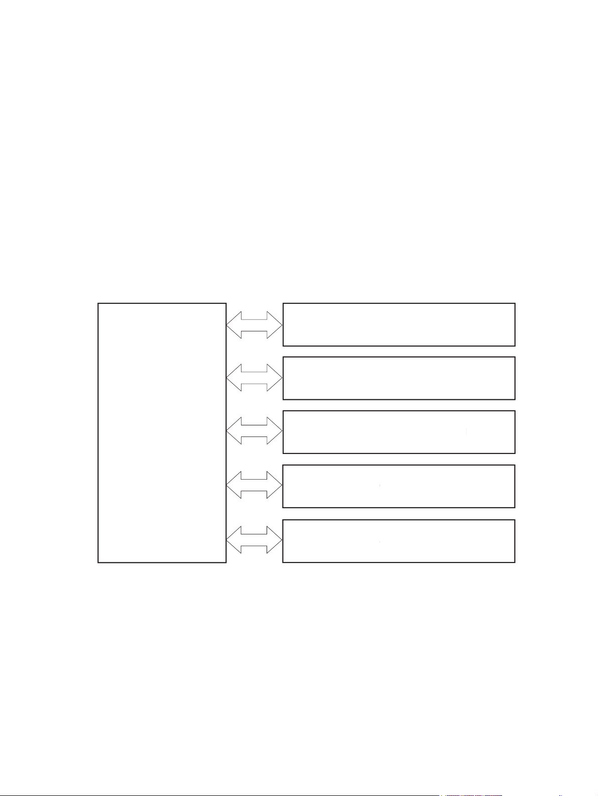
Basic operation
/SC
OL
SYS
O
ON
SC
R
The product routes all high-level processes through the formatter, which stores font information, processes
the print image, and communicates with the host computer.
The basic product operation comprises the following systems:
●
The engine-control system, which includes the power supply and the DC controller
●
The laser/scanner system, which forms the latent image on the photosensitive drum
●
The image-formation system, which transfers a toner image onto the paper
●
The pickup-and-feed system, which uses a system of rollers and belts to transport the paper through
the product
●
The option system, which controls the optional paper feeders
●
The scanner system, which scans data and sends it to the formatter for copying or for sending to email
Figure 1-1 Relationship between the main product systems
LASER/SCANNER SYSTEM
LASER
ANNER SYSTEM
IMAGE-FORMATION SYSTEM
IMAGE-FORMATION SYSTEM
ENGINE CONTROL
ENGINE CONTR
SYSTEM
TEM
The interconnect board (ICB) provides connections from the formatter to the following components:
●
DC controller (DCC)
●
Scanner control board (SCB)
●
Control panel, easy-access USB port, and USB hardware integration pocket through a USB cable
PICKUP-AND-FEED SYSTEM
PICKUP-AND-FEED SYSTEM
OPTION
PTI
ANNE
SCANNER
The formatter receives +5 volts from the low-voltage power supply (LVPS).
The document feeder/scanner receives +24 volts from the scanner power supply, which is powered by an AC
line from the LVPS.
2 Chapter 1 Theory of operation ENWW
Page 27
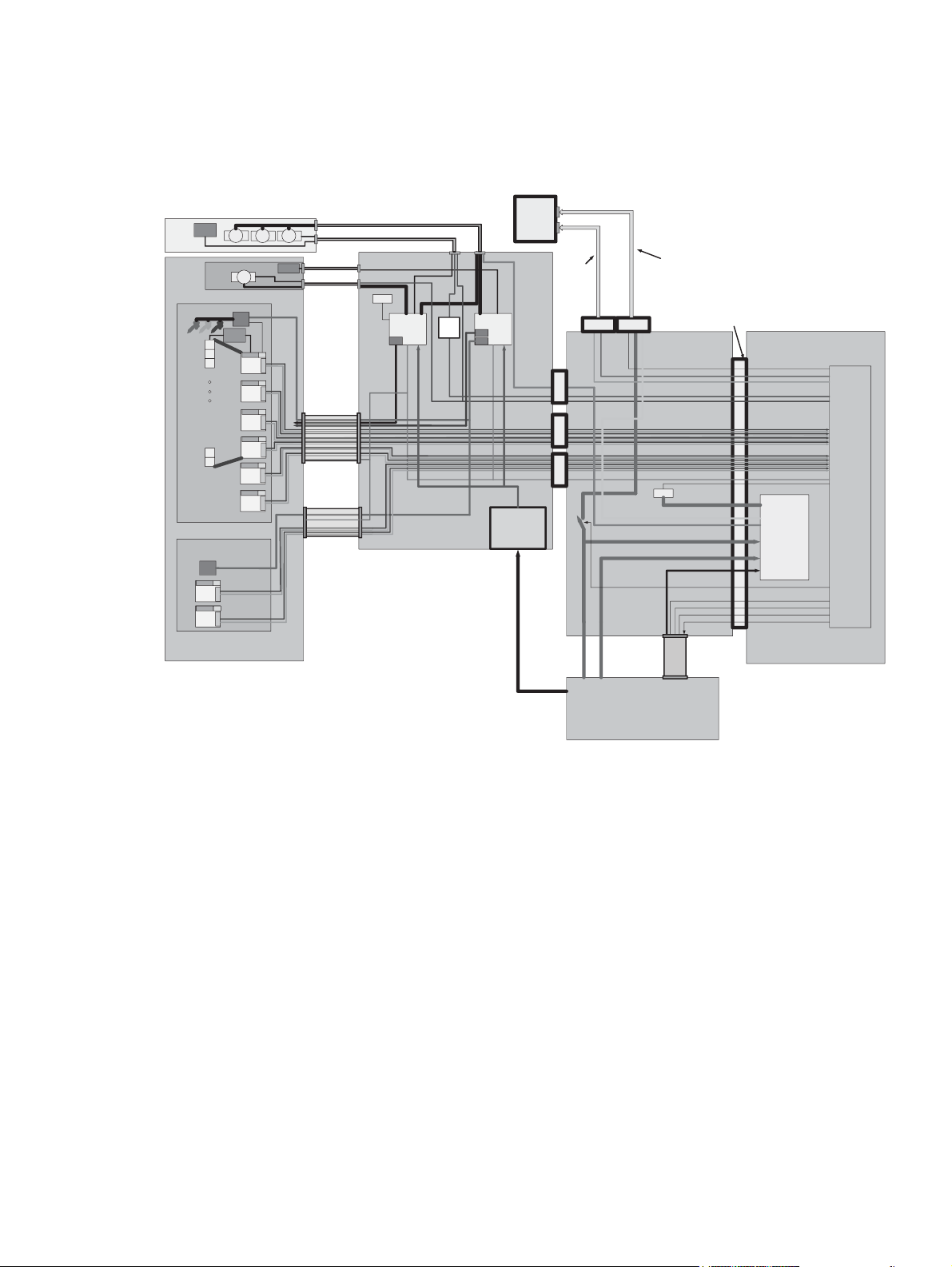
The stapling mailbox receives +24 volts from the LVPS through a line in the JetLink cable connecting the
stapling mailbox to the product.
Figure 1-2 System block diagram
Control Panel Assembly Contains
Sensors
&LEDs
SAT ADF
Asset
A4 E-Dupl ex CIS SCANNER MODULE
Scanner
Timing
Timing
Scanner
Tub
LED
Driver
Walkup USB, HIP Module and
J17
UPS
CIRCUIT
Driver
&P/S
+3.3V
+6.5V
Timing
Generator
(x3 or x4)
ADF DC Motors
FB DC Motor
LED
Driver
Timing
Timing
Timing
Timing
Timing
Timing
A4 Carriage
ADF SENSORS
ADF MOTOR CONTROL
J2
FLATBED SENSORS
Sensors
FLATBED MOTOR
J19
CONTROL
NVRAM
DC Motor
LED
LVDS
LED
LVDS
LED
LVDS
LED
LVDS
LED
LVDS
LED
LVDS
SCANNER FFC
E-Duplex FFC
MICCI-2 channel A/B
MICCI-2 channel C
+5V
MICCI-2 channel E
Scanner ICB
LED
LVDS
LED
LVDS
J18
+3.3V AUX
DC Motor
Driver
&P/S
MICCI-2 channel E
ADF & FB SENSORS
ULTASONIC PICK SIGNALS
+32V
24V to 32V
booster
Contr ol
Panel
Assembly
24V
HDMI
Data
Cable
“Sideband” 12X1 Wire bundle
12-pin SBHDMI
X16 PCI-e Connector
FormatterEngine ICB
+5VSW
+3.3V AUX
USB Switch Control
KEYS
Scanner Signals: 4 Diff Data Pairs&
4DiffClockPairs
E-Duplex Signals: 4 Diff Data Pairs &
4 Diff Clock Pairs
MICCI2 signals
I2C I/F
NVRAM
USB&MassStorage+5V
3.3VStandby
Video I/F
NuBus
Engine FFC
CAN I/F
nENG_ON
Formatter
Power Circuits
USB Data Lines
PCI-express Lines
20Pin
36pin
iPass
1
36pin
iPass
2
+3.3VUSW
Formatter+5V
5V
+
USB/MS
Formatter +5V
ASIC
Engine
ENWW Basic operation 3
Page 28

Sequence of operation (product)
A microprocessor on the DC controller controls the operating sequence of the product. The tables in this
section describe the basic operating sequence, from when the product power is turned on until the final
printed page is delivered to an output bin.
Table 1-1 Sequence of operation (product)
Period Duration Description
Waiting From the time the power is turned on, the door is
closed, or the product exits Sleep mode until the
product is ready for printing
Standby From the end of the waiting sequence or the end of
the last rotation until the formatter receives a
print command or the product is turned off
Initial rotation From the time the formatter receives a print
command until the paper enters the paper path
Print From the time the first sheet of paper enters the
paper path until the last sheet has passed through
the fuser
Last rotation From the time the last sheet of paper exits the
fuser until the motors stop rotating
●
Detects the toner cartridge
●
Cleans the transfer roller
●
Heats the fuser sleeve in the fuser
●
Pressurizes the pressure roller in the fuser
●
The product is in the Ready state.
●
The product enters Sleep mode if the Sleep command is
received from the formatter.
●
Stabilizes the photosensitive drum to prepare for
printing
●
Prepares the laser/scanner unit
●
Forms the image on the photosensitive drum
●
Transfers the toner to the paper
●
Fuses the toner image onto the paper
●
Moves the last printed sheet into the output bin
●
Cleans the transfer roller
●
Stops the high-voltage power supply
●
Stops the laser/scanner unit
●
If the product receives another print command, the
product returns to the initial rotation period when the
last rotation is complete.
●
If the product does not receive another print command,
the product returns to the standby period.
4 Chapter 1 Theory of operation ENWW
Page 29

Sequence of operation (scanner)
Table 1-2 Sequence of operation (scanner)
Period Duration Description
Power on When the product is turned on
Initialization From the end of the power-on period until the
product is ready to scan or copy
Standby From the end of the initialization period until a
request for a scan
Scan From the time immediately following a request for
a scan until the scan is complete
●
Scanner motors rotate
●
Product checks the status of all the sensors
●
Scanner lamp illuminates
●
Optical scan head moves from its home position
●
Scanner calibrates
●
Optical scan head returns to its home position
●
Scanner and document feeder initialization complete
●
Scanner calibrates
●
Document feeder checks for paper in the input tray
●
The product enters Sleep mode if the Sleep command is
received from the formatter.
●
Scan carriage rests in its home position
●
Scanner turns on
●
Scan start position adjusted
●
Scan performed
●
Data sent to the formatter
ENWW Basic operation 5
Page 30

Formatter-control system
The formatter performs the following functions:
●
Controls Sleep mode
●
Receives and processes print data from the various product interfaces
●
Monitors control-panel functions and relays product-status information (through the control panel and
the network or the bidirectional interface)
●
Develops and coordinates data placement and timing with the DC controller
●
Stores font information
●
Communicates with the host computer through the network or the bidirectional interface
The formatter receives a print job from the network or the bidirectional interface and separates it into image
information and instructions that control the printing process. The DC controller synchronizes the imageformation system with the paper-input and -output systems, and then signals the formatter to send the
print-image data.
The formatter also provides the electrical interface and mounting locations for one memory DIMM, the hard
disk drive or solid state module memory device, and the optional analog fax accessory.
Formatter hardware
The formatter system includes the following components.
Table 1-3 Formatter hardware components
Component Function
Microprocessor Stores fonts and microprocessor control programs
Random access memory (RAM) Stores printing and font information and temporarily stores print-image data before sending it to
Nonvolatile random access
memory (NVRAM)
USB Sends and receives data through a USB type B interface connector (connected to the host
Hard-disk drive (HDD)
Solid-state module (SSM)
Real time clock The Wake-up time feature uses this clock. It includes a battery to supply power when the product
HP Jetdirect Inside (JDI) JDI is an Ethernet interface that is part of the formatter.
Sleep mode
the product. RAM data is lost when the product is turned off.
Stores configuration information. NVRAM data is saved when the product is turned off.
computer)
Stores the firmware. A remote firmware upgrade process overwrites and upgrades the firmware
on the HDD or SSM.
is turned off.
NOTE: In the General Settings menu (a submenu of the Administration menu), this item is termed Sleep
Timer Settings.
6 Chapter 1 Theory of operation ENWW
Page 31

This feature conserves power after the product has been idle for an adjustable period of time. When the
product is in Sleep mode, the product retains all settings, downloaded fonts, and macros. The default setting
is for Sleep mode to be enabled, and the product enters Sleep mode after a 30-minute idle time.
The product firmware uses a combination of timers and Sleep settings to control when the product enters a
different state as well as what states the product will enter. The available states are listed below, in
descending order, from using the most power to using the least power:
●
Active: The product control panel is fully illuminated. The power button light is illuminated.
●
Shallow suspend: The product control panel is dim and the content is grayed out, but is still readable.
The power button light is illuminated.
●
Suspend: The product control panel is off (blacked out). The power button light blinks once every three
seconds.
●
Deep suspend: The product control panel is off (blacked out). The power button light blinks once every
three seconds. The control panel and power button appearance is the same in this state as the suspend
state. However, the product is drawing less than 1 watt of power in the deep suspend state (as opposed
to 6 watts of power in the suspend state).
●
Off: This state is entered by pressing the power button or removing power from the product. The power
button light is not illuminated.
The product exits Sleep mode and enters the warm-up cycle when any of the following events occur:
●
The product receives a print job, valid data, or a PML or PJL command.
●
A control-panel button is pressed or the touchscreen is touched.
●
A cover or door is opened.
●
The engine-test switch is pressed.
●
A paper tray, other than Tray 1, is opened.
NOTE: If the product is in the deep suspend state, opening a paper tray will not cause the product to
exit Sleep mode.
NOTE: Product error messages override the Sleep message. The product enters Sleep mode at the
appropriate time, but the error message continues to appear.
TIP: When the product is in Sleep mode, the sub-power supply is off and the low-voltage power supply is
on. The scanner cannot be used when the product is in Sleep mode.
ENWW Formatter-control system 7
Page 32

Input/output (I/O)
The product has three I/O interfaces:
●
Hi-Speed USB 2.0
●
10/100/1000 Ethernet LAN connection with IPv4 and IPv6
●
Easy-access USB printing (no computer required)
CPU
The formatter incorporates an 800 MHz processor.
Memory
This section describes the product random access memory (RAM).
Random access memory (RAM)
RAM on the formatter contains the page, I/O buffers, and the font storage area. It stores printing and font
information received from the host system, and can also serve to temporarily store a full page of print-image
data before the data is sent to the product. The contents of RAM are lost when the product is turned off.
NOTE: If the product encounters a problem when managing available memory, a clearable warning
message displays on the control-panel display.
Firmware
The hard-disk drive (HDD) or solid-state module (SSM) store the firmware. A remote firmware upgrade
process overwrites and upgrades the firmware on the HDD or SSM.
Nonvolatile random access memory (NVRAM)
NVRAM on the formatter stores product and user configuration settings. The contents of NVRAM are retained
when the product is turned off or disconnected.
Image Resolution Enhancement technology
NOTE: Resolution Enhancement technology (REt) settings that are sent from software programs or product
drivers override the control-panel settings.
The formatter contains circuitry for REt, which modifies the standard video dot data on its way to the DC
controller to produce “smoothed” line edges. REt can be turned on or off from the control panel or from some
software programs. The default setting is on.
REt produces print output with smooth angles, curves, and edges. All print resolutions, including FastRes
1200, benefit from using REt.
●
ProRes 1200: produces 1200 dpi printing for the best quality in-line art and graphic images.
●
FastRes 1200: produces 1200 dpi print quality for fast, high-quality printing of business text and
graphics.
8 Chapter 1 Theory of operation ENWW
Page 33

HP Memory Enhancement technology
The HP Memory Enhancement technology (MEt) effectively doubles the amount of standard memory through
a variety of font- and data-compression methods.
NOTE: MEt is available only in when printing in printer command language (PCL) mode. It is not functional
when printing in PostScript (PS) mode.
Printer job language (PJL)
PJL is an integral part of product configuration, in addition to the standard printer command language (PCL)
and PostScript (PS). With standard cabling, the product can use PJL to perform a variety of functions, such as
these:
●
Two-way communication with the host computer through a network connection or a USB device
port: The product can inform the host about the control-panel settings, and the control-panel settings
can be changed from the host.
●
Dynamic I/O switching: The product uses this switching to be configured with a host on each I/O. The
product can receive data from more than one I/O simultaneously, until the I/O buffer is full. This can
occur even when the product is offline.
●
Context-sensitive switching: The product can automatically recognize the personality (PS or PCL) of
each job and configure itself to serve that personality.
●
Isolation of print environment settings from one print job to the next: For example, if a print job is
sent to the product in landscape mode, the subsequent print jobs print in landscape only if they are
formatted for landscape printing.
Printer management language (PML)
PML allows remote configuration of the product and status read-back from the product through the I/O
ports.
Control panel
The control panel is a 20.3 cm (8 in) full-color SVGA with capacitive touchscreen and adjustable viewing
angle. It includes an easy-access USB port for walk-up printing and a hardware integration pocket for thirdparty USB devices, such as card readers.
The control panel has a diagnostic mode to allow testing of the touchscreen, Home button, and speaker. The
control panel does not require calibration.
The M630z model has a QWERTY retractable keyboard beneath the control panel. The keys are mapped to a
specific language in the same way the virtual keyboard on the product control panel is mapped. Selecting a
different keyboard layout for the virtual keyboard remaps the keys on the physical keyboard to match the
new settings.
Scanner interface
The formatter receives data from the scanner to produce copies and to send scanned data in email format.
ENWW Formatter-control system 9
Page 34

Engine-control system
y
y
user co
n
The engine-control system receives commands from the formatter and interacts with the other main
systems to coordinate all product functions. The engine-control system consists of the following
components:
●
DC controller
●
Low-voltage power supply (LVPS)
●
High-voltage power supply (HVPS)
●
Fuser control
This system controls the laser/scanner, image-formation, and pickup-and-feed systems. The microprocessor
on the DC controller controls the operating sequence of the product.
Figure 1-3 Engine control system block diagram
Engine-control system
Engine-control system
DC controller
DC controller
Laser/scanner system
Laser/scanner system
Image-formation system
Image-formation system
Formatter
Formatter
Low-voltage power supply
igh-voltage power suppl
High-voltage power supply
Fuser control
F
ntrol
Pickup, feed and delivery
Pickup, feed and deliver
system
stem
Option
ptio
Scanner
canner
10 Chapter 1 Theory of operation ENWW
Page 35

DC controller
use
sfe
ge
ge
y
ge
y
d
h
h
y
’y
t
The DC controller controls the operation of the product and its components. The DC controller starts the
product operation when the product power is turned on and the power supply sends DC voltage to the DC
controller. After the product enters the standby period, the DC controller sends out various signals to operate
motors, solenoids, and other product components based on the print command and image data that the host
computer sends.
Figure 1-4 DC controller block diagram
Tran
Transfer roller
Cartridge
Fuser
F
artrid
r
r roller
Low-volta
Low-voltage
power supply
ower suppl
igh-volta
High-voltage
ower suppl
power supply
DC controller
DC controller
Motor
tor
Fan
Solenoid
olenoi
Clutch
lutc
Photointerrupter
Photointerrupter
Sensor
ensor
Control panel
ontrol panel
Image scanner
Image scanner
Formatter
Formatter
ICB
ICB
Switch
witc
Accessory
Accessor
Laser scanner ass’y
Laser scanner ass
Duplex unit
uplex uni
ENWW Engine-control system 11
Page 36

Motors
The product has nine motors. The motors drive the components in the paper-feed and image-formation
systems.
The DC controller monitors the feed motor, drum motor, and fuser motor to determine motor failure. The DC
controller does not detect motor failure in the intermediate reverse assembly motor, the reverse assembly
motor, the delivery motor, or the duplex re-pickup motor. Therefore, a jam occurs when one of these motors
fails.
Figure 1-5 Motors
M104
M106
M105
M102
M101
M107
M108
M299
M103
Table 1-4 Motors
Name Purpose
Feed motor (M101) Drives the following rollers: Tray 1 pickup roller, Tray 2 pickup roller, feed roller, and
rollers for the optional paper feeders
Drum motor (M102) Drives the transfer-charging roller, photosensitive drum, and developing cylinder
Cassette lifter motor (M103) Moves the lifting plate
Intermediate reverse assembly motor
(M104)
Reverse assembly motor (M105) Drives the reverse assembly roller
Delivery motor (M106) Drives the intermediate delivery roller and the delivery roller
Duplex re-pickup motor (M107) Drives the duplex feed roller
Scanner motor (M108) Drives the scanner mirror
Fuser motor (M299) Drives the pressure roller and fuser delivery roller; pressurizes or releases the pressure
Drives the intermediate reverse assembly roller
roller
12 Chapter 1 Theory of operation ENWW
Page 37

Fans
The product has seven cooling fans for preventing the temperature from rising in the product.
The DC controller determines a fan failure and notifies the formatter when the fan locks for a specified period
of time from when the fan starts up.
Figure 1-6 Fans
FN107
FN103
FN102
FN105
FN101
FN301
FN104
Table 1-5 Fans
Name Cooling area Type Motor speed Failure detection
Main fan (FN101) Cartridge area, engine
power supply area and
laser scanner area
Laser scanner fan
(FN102)
Cartridge front side fan
(FN103)
Low-voltage power
supply fan (FN104)
Reverse fan (FN105) Reverse area Intake 1-speed Yes
Duplex fan (FN107) Duplex feed area Intake 1-speed Yes
Cartridge fan (FN301) Cartridge area Intake 1-speed Yes
Laser scanner area Intake 1-speed Yes
Cartridge area Intake 1-speed Yes
Low-voltage power
supply area
Intake 2-speed Yes
Intake 2-speed Yes
ENWW Engine-control system 13
Page 38

High-voltage power supply
primary charging rolle
developing rolle
y
g
cui
use
user sleeve
use
cui
e
osens
l
ge
essure rolle
The high-voltage power supply applies biases to the following components:
●
Primary charging roller
●
Developing roller
●
Transfer roller
●
Fuser sleeve
●
Pressure roller
Figure 1-7 High-voltage power supply
DC controll
DC controller
Engine power supp
Engine power supply
F
r
Fuser
ias cir
bias circuit
Primar
Primary
harging bias
charging bias
circuit
F
Fuser
r
F
Fuser sleeve
Pr
Pressure roller
artrid
Cartridge
To primary charging roller
To developing roller
Developin
Developing
ias cir
bias circuit
Photosensitive drum
Phot
Transfer roller
Transfer bias
circuit
itive drum
The primary charging bias is used to charge the surface of the photosensitive drum evenly to prepare for
image formation. The primary charging bias circuit generates the bias.
The developing bias is used to adhere toner to an electrostatic latent image formed on the photosensitive
drum. The developing bias circuit generates the bias.
The transfer bias is used to transfer the toner from the photosensitive drum onto the paper. The transfer bias
circuit generates the bias.
The fuser bias is used to stabilize the paper feed and improve the print quality. The fuser bias circuit
generates the bias.
14 Chapter 1 Theory of operation ENWW
Page 39

Low-voltage power supply
A
ch
061
oss
t
h
t
g
t
on
t
n
t
g
t
V
n
t
on
t
/SOFTSWSNS
/
OX
V
/AC200
T
ock
ch
01
on
t
3V
n
t
G
e
y
h
t
C
h
t
C
y
E
The low-voltage power supply converts the AC power from the power source into the DC voltage that the
product components use.
Figure 1-8 Low-voltage power supply circuit
AC power
C power
Low-voltage power supply
Low-voltage power suppl
DC controller
DC controller
ectifyin
Rectifying
ircui
circuit
+5V
eneratio
generation
ircui
circuit
Protecti
Protection
ircui
circuit
Fuse
FU1
Fuse
FU2
rocr
Zerocross
ircui
circuit
witc
Switch
ircui
circuit
ectifyin
Rectifying
circuit
Engin
Engine
ower suppl
power supply
ircui
Fuser
Power swit
Power switch
W1
24
+24V
ircui
circuit
circuit
ircui
SW1061
/SOFTSWSNS
PSREM24
PSREM24V
PFC-Z PWRRM
PFC-Z PWRRMT
PWR_SAVE
PWR_SAV
Interl
Interlock
wit
switch
W1
SW101
ZER
/ZEROX
24VA
+24VA
24VB
+24VB
/AC200
24VB
+24VB
24VB
+24VB
r
eneratio
generation
Protection
Protecti
+3.3VB
.3VB
.3VA
+3.3VA
24VB
+24VB
24VA
+24VA
Switch
witc
circuit
ircui
+24VC
24V
+3.3VB
Switch
witc
circuit
ircui
.3VB
ICB
ICB
rmatter
Formatter
WAKE_ENG
WAKE_EN
WAKE_VC
WAKE_V
+5VA
VA
.
+3.3V
generation
eneratio
circuit
ircui
+3.3VA
.3VA
Protection
Protecti
circuit
ircui
The low-voltage power supply converts the AC power into three DC voltages, which it then subdivides, as
described in the following table.
ENWW Engine-control system 15
Page 40

Table 1-6 Converted DC voltages
DC voltage Behavior
+24VA Stopped when the product is turned off or is in Sleep mode
+24V
+5V +5VA Constantly supplied
+3.3V
+24VB Interrupted when the cartridge door opens
+24VC Interrupted when the product detects no fuser installed
+3.3VA Constantly supplied
+3.3VB Stopped when the product is turned off or is in Sleep mode
Overcurrent/overvoltage protection
The low-voltage power supply automatically stops supplying the DC voltage to the product components
whenever it detects excessive current or abnormal voltage. The low-voltage power supply has a protective
circuit against overcurrent and overvoltage to prevent failures in the power supply circuit.
CAUTION: If DC voltage is not being supplied from the low-voltage power supply, the protective function
might be running. In this case, turn the power switch off and unplug the power cord.
Do not turn the power switch on until the root cause is found and corrected.
If the protective function is active, the DC controller notifies the formatter of a low-voltage power supply
failure. In addition, the low-voltage power supply has two fuses (FU1 and FU2) to protect against overcurrent. If over-current flows into the AC line, the fuses stop the AC power.
Voltage detection
The product detects the power supply voltage that is connected to the product. The DC controller monitors
the POWERSUPPLY VOLTAGE (/AC200) signal and detects power supply voltage, whether 100 volts or 200
volts, to control the fuser operation. The DC controller determines a low-voltage power supply failure and
notifies the formatter when the power supply voltage is out of a specified range.
Safety
For personal safety, the product interrupts +24VB power when the interlock switch is turned off. As a result,
the DC voltage to the following components stops. See
●
Low-voltage power supply
●
High-voltage power supply
●
Fuser motor (M299)
●
Laser scanner fan (FN102)
●
Cartridge front-side fan (FN103)
●
Reverse fan (FN105)
●
Cartridge fan (FN301)
Table 1-6 Converted DC voltages on page 16.
16 Chapter 1 Theory of operation ENWW
Page 41

WARNING! The remote switch control circuit turns the product power on or off such that AC power flows
even when the power switch is turned off. Unplug the power cord before disassembling the product.
Sleep (power save) mode
Sleep mode conserves energy by stopping the power to several components when the product is idle. The DC
controller determines a low-voltage power supply failure and notifies the formatter if the power supply of
+24 volts is lower than a specified value when the product exits Sleep mode and enters the standby period.
Low-voltage power supply functions
The product has the following low-voltage power supply functions.
Table 1-7 Low-voltage power supply functions
Function Supported feature
Sleep mode Yes
Power supply voltage detection Yes
Automatic power OFF No
Automatic power ON/OFF No
Active OFF Yes
Inactive OFF Yes
Network mode No
Power switch illumination Yes
Low-voltage power supply failure detection Yes
ENWW Engine-control system 17
Page 42

Fuser control
y
1
1
2
e
cui
2
signal
essure rolle
e
The fuser heater control circuit and the fuser heater safety circuit control the fuser temperature according to
commands from the DC controller. The product uses an on-demand fusing method.
Figure 1-9 Fuser components
1, H
H1, H2
TH2
TH
TH1
TH
TP
TP1
FUSER TEMPERATURE signal
FUSER
FUSER HEATER CONTROL signal
Fuser sleeve
r sleev
Pressure roller
Pr
Fuser heater control
r heater control
circuit
ir
Low-voltage power supply
Fuser heater safety
Fuser heater safet
circuit
DC controller
DC controll
Table 1-8 Fuser components
Component name Function
H1 Fuser main heater Heats the fuser sleeve
H2 Fuser sub-heater Heats the fuser sleeve
TH1 Main thermistor Detects the temperature at the center of the fuser heater
(contact type)
TH2 Sub-thermistor Detects the temperature on one end of the fuser heater (contact
type)
TP1 Thermoswitch Prevents an abnormal temperature rise of the fuser heater
(contact type)
18 Chapter 1 Theory of operation ENWW
Page 43

Fuser temperature control
1
1
/FS
I
/AC200
e
/RLD
/
OX
S
E
001L101
user co
2
essure rolle
2100V200V
oss
l
t
on
use
cui
use
i
02
t
user sleeve ass’
use
t
)
The fuser temperature control maintains the temperature of the fuser heater at its targeted temperature.
The DC controller detects the fuser temperature by monitoring the FUSER TEMPERATURE (FSRTH1 and
FSRTH2) signals. The DC controller outputs the FUSER HEATER CONTROL (FSRD1 and FSRD2) signals, so that
the fuser heater control circuit controls the fuser heater accordingly.
Figure 1-10 Fuser circuit
RL101
RL102
F
r heater
Fuser heater
ntrol cir
control circuit
L1
AC inpu
AC input
Low-vol
Low-voltage power supply (LPU)
F
Fuser control
Zerocr
Zerocross
circuit
elay contro
Relay control
circuit
urren
Current
tecti
detection
circuit
ntrol
ZER
/ZEROX
/RLD
FSRSAF
FSRSAFE
RRM
CURRMS
FSRD1
FSRD
FSRD
FSRD2
FSRTH2
DC controll
DC controller
F
r heater
Fuser heater
afety circu
safety circuit
TH2
TP1
TH1
1, H
H1, H2
Pr
Pressure roller
Engine power supply (EPU
Engine power supply (EPU)
P1
JP1001
100V: Open
200V: Close
F
r
Fuser
F
Fuser sleeve ass’y
/AC200
FSRTH1
H
/FSRARI
RAR
ENWW Engine-control system 19
Page 44

Fuser sleeve temperature protection
Fuser heater protection is a feature that detects excessive temperatures in the fuser and interrupts the
power supply to the fuser heater.
The following three protective components prevent the fuser heater from reaching excessive temperatures:
●
DC controller: The DC controller monitors the detected temperature of the thermistors. The DC
controller deactivates the FUSER HEATER CONTROL signal and releases the relays (RL101 and RL102) to
interrupt power supply to the fuser heater when it detects an excessive temperature.
●
Fuser heater safety circuit: The fuser heater safety circuit monitors the detected temperature of the
thermistors. The fuser heater safety circuit deactivates the FUSER HEATER CONTROL signal and
releases the relays (RL101 and RL102) to interrupt power supply to the fuser heater when it detects an
excessive temperature.
●
Thermoswitch: If the temperature of the fuser heater is abnormally high, the contact of the
thermoswitch breaks to interrupt power supply to the fuser heater.
Fuser failure detection
The DC controller determines if the fuser functions properly. The DC controller determines a fuser failure,
interrupts power supply to the fuser heater, and notifies the formatter of a failure status when it encounters
any of following conditions:
●
Abnormal temperature rise
◦
The main thermistor does not detect 15°C (59°F) or higher within a specified period of time from
when the fuser heater is turned on.
◦
The main thermistor does not detect 100°C (212°F) or higher within a specified period of time from
when the fuser heater is turned on.
◦
The main thermistor does not detect targeted temperature minus 5°C (41°F) within a specified
period of time from when the fuser heater is turned on.
●
Abnormally low temperature
◦
The main thermistor detects 49°C (120.2°F) or lower continuously for a specified period of time
after it once detects 100°C (212°F) or higher.
◦
The main thermistor detects targeted temperature minus specified degrees or lower continuously
for a specified period of time after the TOP signal for the first page is output.
◦
The sub-thermistor detects 49°C (120.2°F) or lower continuously for a specified period of time
after it once detects 100°C (212°F) or higher.
●
Abnormally high temperature
◦
The main thermistor detects 255°C (491°F) or higher.
◦
The sub-thermistor detects 285°C (545°F)or higher.
●
Frequency detection circuit failure
◦
The ZEROCROSS signal is not detected within a specified period of time after the product is turned
on.
●
Fuser-presence detection
20 Chapter 1 Theory of operation ENWW
Page 45

The DC controller determines if the fuser is installed in the product and notifies the formatter when it
detects the fuser is absent. The DC controller detects fuser presence from the FUSER PRESENCE (/
FUSERARI) signal when any of the following occurs:
◦
The product is turned on.
◦
The door is closed.
Pressure roller cleaning
The formatter periodically initiates the pressure roller cleaning function to clear the toner accumulated on
the pressure roller surface by transferring it to a piece of paper. Following is the operational sequence of
pressure roller cleaning:
1. The DC controller initiates picking a sheet of paper from the designated input source when it receives
the cleaning command from the formatter.
2. The fuser motor repeatedly drives-and-stops at a specified interval when the trailing edge of the paper
passes through the transfer roller. The fuser heater is turned on-and-off at the same time.
3. The fuser fuses the toner adhered to the pressure roller surface onto the paper; thus, cleaning the
pressure roller.
4. The paper with the fused toner exits the product.
Ambient-temperature detection
The product contains an environmental sensor (TH3) that measures the air temperature of the surrounding
environment. The product automatically adjusts the temperature settings in the fuser to adjust for changes
in the ambient temperature.
ENWW Engine-control system 21
Page 46

Laser/scanner system
e
osens
aser ass’
The DC controller controls the laser scanner system according to commands from the formatter. The DC
controller controls the internal components in the laser scanner system to form a latent electrostatic image
on the photosensitive drum according to the VIDEO signals.
The following are the main components of the laser scanner system:
●
Laser assembly
●
Scanner motor assembly
●
Beam Detect (BD) sensor
●
Scanning mirror
●
BD mirror
Figure 1-11 Laser/scanner
DC controller
DC controll
Laser ass’y
L
Scanning mirror
canning mirror
BD mirror
BD mirror
Scanner motor ass’y
canner motor ass’
Photosensitive drum
Phot
itive drum
BD sensor
BD sensor
22 Chapter 1 Theory of operation ENWW
Page 47

Laser/scanner failure
The DC controller determines an optical unit failure and notifies the formatter of the error status when any of
the following occurs:
●
Beam Detect (BD) failure: The BD signal is not detected within a specified period of time from when the
laser/scanner starts. Or, a specified BD interval is not detected within a specified period of time from
when the laser/scanner is ready.
●
Laser/scanner motor startup failure: The scanner motor does not reach a specified rotation frequency
within a specified period of time from when the laser/scanner starts up.
●
Laser/scanner motor abnormal rotation: The laser/scanner motor does not reach a specified
rotational frequency within a specified period of time during a print operation.
Safety
The laser/scanner assembly has a mechanical laser shutter. For the safety of users and service technicians,
the laser shutter interrupts the optical path of the laser/scanner assembly when the top door is opened
(SW101).
ENWW Laser/scanner system 23
Page 48

Image-formation system
e
aser scanner ass’
use
ge
The DC controller controls the image-formation system according to commands from the formatter. The DC
controller controls the internal components of the image-formation system to form the toner image on the
photosensitive drum surface, transfer the image to the paper, and then fuse it to the paper.
The following are the main components of the image-formation system:
●
Toner cartridge
●
Transfer roller
●
Fuser
●
Laser/scanner assembly
●
Engine power supply
Figure 1-12 Image-formation system components
Image scanner
Image scanner
Laser scanner ass’y
L
F
r
Fuser
Engine power supply
Engine power suppl
DC controller
DC controll
The DC controller rotates the drum motor to drive the following components:
Toner
Toner
artrid
Cartridge
Transfer roller
24 Chapter 1 Theory of operation ENWW
●
Photosensitive drum
●
Developing roller
Page 49

●
e
e
e
ge
osens
e
use
essure rolle
user sleeve
use
Primary charging roller (follows the photosensitive drum)
●
Transfer roller (follows the photosensitive drum)
The DC controller rotates the fuser motor to drive the following components:
●
Pressure roller
●
Fuser sleeve (follows the pressure roller)
Figure 1-13 Image-formation system motor control
Image scanner
Image scanner
Fuser sleeve
F
Toner
Toner
Cartridge
artrid
Primary charging roller
Primary charging roll
Developing roll
Developing roller
Drum motor
Drum motor
Pressure roller
Pr
Fuser motor
F
r motor
Fuser
F
r
DC controller
DC controll
Transfer roller
Phot
Photosensitive
drum
drum
itiv
ENWW Image-formation system 25
Page 50

Electrophotographic process
e
g
g
k
k
k
ock
h
k
on
y
n
p
p
g
Following are the stages of the electrophotographic process (image formation):
Figure 1-14 Stages of image-formation
Electrostatic latent image formation block
Electrostatic latent image formation bloc
8. Drum charge elimination
leaning bloc
Cleaning block
Paper delivery
Paper deliver
. Fusin
6. Fusing
Fusing block
Fusing bloc
2. Laser beam exposure
2. Laser beam exposur
1. Primary charge
7. Drum cleanin
7. Drum cleaning
5. Separation
Transfer block
Transfer bl
. Developin
3. Developing
4. Transfer
Paper picku
Paper pickup
Paper path
Paper pat
Direction of drum rotation
Direction of drum rotati
Developing block
Developing bloc
egistratio
Registration
Tray 1 picku
Tray 1 pickup
26 Chapter 1 Theory of operation ENWW
Page 51

Step 1: Primary charge (conditioning)
osens
e
aser bea
osens
The primary-charging roller in the toner cartridge applies a uniform negative charge to the surface of the
drum. The primary-charging roller is made of conductive rubber. An AC bias applied to the roller erases any
residual charges from any previous image. The charging roller applies a negative DC bias to create a uniform
negative potential on the drum surface.
Figure 1-15 1. Primary charge (conditioning)
Primary charging roller
Primary charging roll
Photosensitive drum
Phot
itive drum
Primary charging bias
Primary charging bias
Step 2: Laser-beam exposure (writing)
Two laser diodes project laser beams onto a rotating scanning mirror. As the mirror rotates, the beams
reflect off of the mirror, first through a set of focusing lenses, then off a mirror, and finally through a slot in
the top of the toner cartridge, and onto the photosensitive drum. The twin beams sweep the drum from left
to right, discharging the negative potential wherever the beams strike the surface. This creates a latent
electrostatic image, which later is developed into a visible image.
Figure 1-16 2. Laser-beam exposure (writing)
Phot
Photosensitive drum
Laser beam
L
itive drum
m
ENWW Image-formation system 27
Page 52

Step 3: Developing
e
osens
e
osens
e
At this stage of the process, the latent electrostatic image is present on the drum. The toner particles obtain
a negative surface charge by rubbing against the developing cylinder, which is connected to a negative DC
supply. The discharged (exposed, grounded) areas of the drum attract the negatively charged toner, and the
negatively charged (unexposed) areas repel the toner.
Figure 1-17 3. Developing
Developer blade
Developer blad
Developing roller
Developing roll
Developing bias
Developing bias
Step 4: Transfer
During the transfer process, the toner image on the drum surface transfers to the paper. The transfer
charging roller applies a positive charge to the back of the paper, which attracts the negatively charged toner
on the drum surface to the paper.
Figure 1-18 4. Transfer
Phot
Photosensitive
Transfer roller
Photosensitive drum
Phot
itiv
rum
drum
Transfer bias
itive drum
Paper
Paper
28 Chapter 1 Theory of operation ENWW
Page 53

Step 5: Separation
osens
e
ush
user bias
user bias
user sleeve
use
essure rolle
During the separating process, the paper separates from the drum. To stabilize the feed system and to
prevent dropouts on the printed image at low temperature and humidity, the static-charge eliminator
reduces the charge on the back of the paper.
Figure 1-19 5. Separation
Static charge eliminator
Step 6: Fusing
Photosensitive
Phot
Transfer roller
drum
rum
itiv
Paper
Paper
During the fusing process, heat and pressure fuse the toner to the paper in order to produce a permanent
image. The paper passes between a heated fuser element and a soft pressure roller. This melts the toner and
presses it into the paper.
Figure 1-20 6. Fusing
F
r heater
F
Fuser sleeve
F
Fuser bias
Fuser heater
Brush
Br
Pr
Pressure roller
Toner
Paper
Paper
F
Fuser bias
ENWW Image-formation system 29
Page 54

Step 7: Drum cleaning
osens
e
e
e
The cleaning blade is in contact with the surface of the drum at all times. As the drum rotates during printing,
the cleaning blade scrapes excess toner into the waste-toner receptacle.
Figure 1-21 7. Drum cleaning
leaning blad
Cleaning blade
Waste toner
Waste toner
receptacle
eceptacl
Phot
Photosensitive
rum
drum
itiv
30 Chapter 1 Theory of operation ENWW
Page 55

Toner cartridge
y
g
e
e
5
e
ge
osens
e
p
The toner cartridge consists of a reservoir of toner and the following components:
●
Photosensitive drum
●
Developing roller
●
Primary charging roller
●
Memory chip
Figure 1-22 Toner Cartridge
DC controll
DC controller
Engine power supply
Engine power suppl
Drum motor
Drum motor
artridge sensor
Cartridge sensor
PS11
PS115
emory chi
Memory chip
Memory chip
The memory chip is non-volatile memory that stores information about the usage of the toner cartridge. The
product reads and writes the data in the memory chip.
The DC controller determines a memory chip error and notifies the formatter when it fails to either read from
or write to the memory chip.
Cartridge presence and life detection
The DC controller performs the following functions related to both detecting the presence of the toner
cartridge and determining the remaining life of the cartridge:
Primary
Primar
charging
hargin
roller
roll
Developing roll
Developing roller
Phot
Photosensitive
drum
drum
itiv
artrid
Cartridge
●
Cartridge presence detection: The DC controller detects the presence of the cartridge by monitoring
the cartridge sensor (PS115) when both of the following occur:
ENWW Image-formation system 31
Page 56

◦
The product is turned on.
◦
The door is closed.
The DC controller notifies the formatter when it detects the cartridge is missing.
●
Toner level detection: The DC controller detects the remaining toner in the cartridge according to the
TONER LEVEL signal, and then notifies the formatter of the remaining toner level.
●
Cartridge life detection: The DC controller detects the cartridge life by monitoring the total operating
time or remaining toner level of the toner cartridge. The DC controller determines a cartridge is at the
end of life and notifies the formatter when total operating time of the cartridge reaches a specified
period of time or the cartridge runs out of toner.
32 Chapter 1 Theory of operation ENWW
Page 57

Pickup, feed, and delivery system
e
k
k
The DC controller controls the pickup, feed, and delivery system according to commands from the formatter.
This system consists of three parts:
●
The pickup-and-feed block encompasses the paper path from each tray to the fuser entrance.
●
The fusing, reverse, and delivery block encompasses the paper path from the fuser entrance to the
output device.
●
The duplex block emcompasses the paper path to reverse the paper in the duplex reverse area for twosided printing
Figure 1-23 Pickup, feed, and delivery system
Fusing, switchback, and delivery block
using, switchback, and delivery block
Fusing, reverse, and delivery block
Duplex block
Duplex bloc
DC controller
DC controll
Pickup-and-feed block
Pickup-and-feed bloc
Simplex paper path
implex paper path
Duplex paper path
Duplex paper path
ENWW Pickup, feed, and delivery system 33
Page 58

Figure 1-24 Sensor locations
PS110
PS109
PS111
PS113
PS907
PS107
PS101
PS106
PS108
PS102
PS103
PS114
PS112
PS104
PS700
PS699
SW102
Table 1-9 Sensors
Abbreviation Component Replacement part number
PS101 Tray 2 media out sensor Paper pickup assembly (RM1-5919-000CN)
PS102 Pre-feed sensor Part not available
PS103 TOP sensor Part not available
PS104 Output bin media-full sensor Part not available
PS106 Media width sensor 1 Part not available
PS107 Tray 2 media stack surface sensor 1 Paper pickup assembly (RM1-5919-000CN)
PS108 Media width sensor 2 Part not available
PS109 Duplex side registration sensor Duplex assembly kit (B3G84-67903)
PS110 Reverse sensor Reverse assembly (RM2-5799-000CN)
PS111 Reverse jam sensor Reverse assembly (RM2-5799-000CN)
PS112 Delivery sensor Reverse assembly (RM2-5799-000CN)
PS113 Duplex re-pickup sensor Duplex assembly kit (B3G84-67903)
PS114 Tray 1 media out sensor MP (Tray 1) pickup assembly (RM2-5822-000CN)
PS115 Cartridge sensor Cartridge sensor assembly (RM1-8323-000CN )
PS699 Fuser pressure release sensor Fuser replacement kit, 110V (B3M77-67903)
Fuser replacement kit, 220V (B3M78-67903)
PS700 Fuser delivery sensor Fuser replacement kit, 110V (B3M77-67903)
Fuser replacement kit, 220V (B3M78-67903)
34 Chapter 1 Theory of operation ENWW
Page 59

Table 1-9 Sensors (continued)
05
06
06L105
99107L102
01
01101103
02
e
ease ca
Abbreviation Component Replacement part number
PS907 Tray 2 media stack surface sensor 2 Paper pickup assembly (RM1-5919-000CN)
SW102 Tray 2 media size switch Size detect cable (RM1-7179-000CN)
Figure 1-25 Motor, clutch, and solenoid locations
M104M106
1
104
verse roller
Reverse roller
disengagement arm
disengagement arm
M102
M105
SL106SL105
L1
1
1
Face-up flapper
Face-up flapper
Tray pickup arm
Tray pickup arm
Fuser pressure
user pressur
release cam
M299
2
M107
l
Side registration guide
m
SL101
Lifter
L1
Cam
am
SL102
M101M103
Table 1-10 Motors, clutch, and solenoids
Abbreviation Component Replacement part number
CL101 Media feed clutch Paper feed roller assembly (RM1-8411-010CN)
M101 Feed motor Feed motor assembly (RM2-5942-000CN)
M102 Drum motor Drum motor assembly (RM1-8358-000CN)
M103 Tray 2 lifter motor Lifter assembly (RM1-5914-000CN)
CL101
L1
M104 Intermediate reverse assembly motor Reverse assembly (RM2-5799-000CN)
M105 Reverse motor Reverse assembly (RM2-5799-000CN)
M106 Delivery motor Reverse assembly (RM2-5799-000CN)
ENWW Pickup, feed, and delivery system 35
Page 60

Table 1-10 Motors, clutch, and solenoids (continued)
05W103
1W102
01
00
Abbreviation Component Replacement part number
M107 Duplex re-pickup motor Duplex assembly kit (B3G84-67903)
M108 Scanner motor (not shown) Laser/scanner assembly (RM1-8406-000CN)
M299 Fuser motor Fuser motor assembly (RM1-5051-020CN)
SL101 Tray 2 pickup solenoid Paper pickup assembly (RM1-5919-000CN)
SL102 Tray 1 pickup solenoid MP (Tray 1) pickup assembly (RM2-5822-000CN)
SL105 Face-up solenoid Reverse assembly (RM2-5799-000CN)
SL106 Reverse roller disengagement solenoid Reverse assembly (RM2-5799-000CN)
Figure 1-26 Switch locations
SW104
W
SW1
SW103
W1
W7
SW700
SW101
SW102
SW105
W1
Table 1-11 Switches
Abbreviation Component Replacement part number
SW1061 Power switch Power switch assembly (RM2-5818-000CN)
SW101 Interlock switch Door switch cable assembly (RM2-7478-000CN)
SW102 Tray 2 media size switch Part not available
36 Chapter 1 Theory of operation ENWW
Page 61

Table 1-11 Switches (continued)
Abbreviation Component Replacement part number
SW103 Face-up bin detection switch Part not available
SW104 Output accessory detection switch Push button switch assembly (RM1-7374-000CN)
SW105 Tray 2 door open detection switch Right door sensor assembly (RM1-1045-000CN)
SW106 Cartridge door open detection switch (not shown) Door sensor cable assembly (RM2-7476-000CN)
SW700 Test-print switch DC controller PCA assembly (RM2-7458-000CN)
ENWW Pickup, feed, and delivery system 37
Page 62

Pickup-and-feed block
The pickup-and-feed block picks one sheet of paper from the tray and feeds it into the fuser.
Figure 1-27 Pickup-and-feed block
Tray 1
Tray 1
Tray 2
38 Chapter 1 Theory of operation ENWW
Page 63

Tray 2 pickup
e
p
01L101
d
e
The operational sequence of picking one sheet of paper from Tray 2 is as follows:
1. The DC controller rotates the feed motor when it receives a print command from the formatter.
2. The Tray 2 pickup roller, Tray 2 feed roller, and Tray 2 separation roller rotate.
3. The Tray 2 pickup solenoid drives at a specified timing.
4. The Tray 2 pickup cam rotates.
5. As the Tray 2 pickup arm lowers, the Tray 2 pickup roller touches the surface of the top sheet of paper.
6. The Tray 2 separation roller removes any multiply-fed sheets.
7. One sheet of paper feeds into the product.
Figure 1-28 Tray 2 pickup
DC controller
DC controll
M101
1
Feed motor
motor
2
1
Tray 2 pickup solenoid
Tray 2 pickup solenoi
Tray 2 pickup roller
Tray 2 pickup roller
SL101
Tray 2 pickup arm
Tray 2 pickup arm
Lifting plate
Liing plat
Tray 2 feed roller
Tray 2 feed roller
Tray 2 separation roller
Tray 2 separation roller
Tray 2 pickup cam
Tray 2 pickup cam
1: The Tray 2 pickup cam rotates
1:The Tray 2 pickup cam rotates
2: The Tray 2 pickup arm lowers.
The Tray 2 pickup arm lowers.
3
3: The Tray 2 pickup roller picks
:The Tray 2 pickup roller picks
up the paper.
up the
ENWW Pickup, feed, and delivery system 39
Page 64

Tray 2 paper-size detection and tray-present detection
The DC controller determines the size of the paper loaded in Tray 2 and also whether the tray is installed in
the product by monitoring the Tray 2 media size switch. The DC controller notifies the formatter when the
detected paper size does not match the size specified by the formatter or if the tray is absent.
The Tray 2 media size switch contains three sub-switches. The DC controller detects the size of the paper and
the presence of the tray based on the combination of the switches.
Table 1-12 Tray 2 media-size detection switch components
Tray presence or media size Top switch Center switch Bottom switch
A4 On Off Off
Letter Off On Off
B5 Off On On
A5 Off Off On
Executive On Off On
LegalOnOnOff
Custom size On On On
No tray Off Off Off
40 Chapter 1 Theory of operation ENWW
Page 65

Tray 2 lift operation
e
e
sensor
The Tray 2 lift operation keeps the paper stack surface at the correct pickup position.
The DC controller detects the position of the stack surface by monitoring the Tray 2 media stack surface
sensors under the following conditions:
●
When the product is turned on
●
When the tray is inserted
●
When the paper stack surface in the tray lowers
Figure 1-29 Tray 2 lift operation
Tray lifter motor
Tray lifter motor
DC controller
DC controll
Tray media
Tray media
stack surface sensor 2
Tray media
Tray media
stack surface sensor 1
Tray media
Tray media
presence sensor
Tray media stack surface sensor lever
Tray media stack surface sensor lever
Lifting plate
Liing plat
The sequence of the Tray 2 lift operation is as follows:
1. The DC controller rotates the Tray 2 lifter motor.
2. The lifter moves up.
3. The tray lifter motor stops when the tray media stack surface sensor 2 detects the paper stack surface.
4. The tray lifter motor rotates again when the tray media stack surface sensor 1 detects that the paper
stack surface lowers.
NOTE: The DC controller determines a tray lifter motor failure and notifies the formatter if the tray
media stack surface sensor 1 or sensor 2 does not detect the paper stack surface within a specified
period of time after the tray lifter motor starts rotating.
Tray 2 paper-presence detection
Lifter
Tray media presence sensor lever
Tray media presence sensor lever
The DC controller detects the presence of paper in Tray 2 by monitoring the Tray 2 media presence sensor.
When this sensor does not detect paper in the tray, the DC controller notifies the formatter.
ENWW Pickup, feed, and delivery system 41
Page 66

Tray 2 multiple-feed prevention
>
eed>
In Tray 2, the separation roller prevents multiple sheets of paper from entering the paper path. The Tray 2
pickup roller drives the separation roller through a sheet of paper.
The rotation of the Tray 2 feed roller through the sheet drives the separation roller. Because the feed roller is
equipped with a torque limiter, only one sheet feeds into the product.
The low friction force between the sheets weakens the driving force from the Tray 2 feed roller. Therefore,
the separation roller is driven by its own driving force and holds back any multiply-fed sheets from the
cassette.
Figure 1-30 Multiple-feed prevention
Tray 2 pickup roller
Tray 2 pickup roller
Paper
Paper
Tray 2 feed roller
Tray 2 feed roller
Tray 2 separation roller
Tray 2 separation roller
Tray 2 separation roller follows
Tray 2 separation roller follows
the Tray 2 feed roller
the Tray 2 feed roller
Driving force from the feed motor
Driving force from the feed motor
Normal-f
<Multiple-feed><Normal-feed>
Multiple-feed
42 Chapter 1 Theory of operation ENWW
Page 67

Tray 1 pickup
e
01L102
1
e
eed moto
Tray 1 pickup solenoi
r
1
e
a
Figure 1-31 Tray 1 pickup
Tray 1
Tray
feed roller
roll
DC controller
DC controll
Feed motor
F
Tray
Tray 1
pickup roller
ickup roll
r
SL102
1
M101
Tray 1 pickup solenoid
Paper
Paper
Tray 1 separation roller
Tray 1 separation roller
PS114
PS114
Tray 1 media presence sensor
Tray 1 media presence senso
Tray 1 pickup cam
Tray 1 pickup c
Lifting plate
The operational sequence of picking one sheet of paper from Tray 1 is as follows:
1. The DC controller rotates the feed motor when it receives a print command from the formatter.
2. The Tray 1 pickup solenoid drives at a specified timing.
3. The Tray 1 pickup roller rotates.
4. The Tray 1 pickup cam rotates and the lifting plate moves up.
5. The Tray 1 pickup roller touches the surface of the top sheet of paper.
6. The Tray 1 separation roller removes any multiply-fed sheets.
7. One sheet of paper feeds into the product.
NOTE: Multiple-feed prevention for Tray 1 is the same mechanism as that for Tray 2. See Tray 2
multiple-feed prevention on page 42
ENWW Pickup, feed, and delivery system 43
Page 68

Tray 1 paper-presence detection
The DC controller detects the presence of paper in Tray 1 by monitoring the Tray 1 media presence sensor
during the initial rotation period when the product is turned on or when the product exits Sleep mode.
Feed speed control
The feed speed control adjusts the feed speed to improve the print quality depending upon the paper type.
The DC controller feeds the paper at a specified speed, depending on the print mode designated by the
formatter.
Table 1-13 Feed speed control
Print mode Feed speed
Auto NA NA
Normal 1/1, 1/2 1/2
Heavy media 1 1/1, 1/2 1/2
Heavy media 2 1/2 1/2
Light media 2 1/1, 1/2 1/2
OHT 1/2 1/2
Legal / Letter / A4 Executive / B5 / A5 / Any custom
44 Chapter 1 Theory of operation ENWW
Page 69

Skew-feed prevention
Paper
The product can straighten the paper without slowing the feed operation. The operational sequence of skewfeed prevention is as follows:
1. The leading edge of paper strikes the registration shutter, and the leading edge aligns with the shutter.
2. As the feed rollers keep pushing the paper, the paper warps.
3. When the force is great enough, the registration shutter opens, and the paper passes through and
straightens.
Figure 1-32 Skew-feed prevention
Paper
Registration shutter
egistration shutter
Paper
aper
Registration shutter
egistration shutter
ENWW Pickup, feed, and delivery system 45
Page 70

Paper-length detection
The DC controller determines the paper length by measuring the time between when the leading edge of the
paper reaches the TOP sensor and when the trailing edge passes through.
The DC controller determines a paper size mismatch and notifies the formatter in one of the following
conditions:
●
The detected paper size is different from the size designated by the formatter.
●
The detected paper size is different from the size detected by the Tray 2 media size switch (only when
printing from Tray 2).
Paper-width detection
The DC controller determines the paper width by analyzing the combination of media width sensor readings.
The DC controller determines a paper size mismatch and notifies the formatter in one of the following
conditions:
●
The detected paper size is different from the size designated by the formatter.
●
The detected paper size is different from the size detected by the Tray 2 media size switch (only when
printing from Tray 2).
Table 1-14 Paper-width detection
Media width sensor 1 (PS106) Media width sensor 2 (PS108) Detection
ON ON Regular size
A4, Letter and Legal
OFF OFF Small size
Executive, B5 and A5
OFF ON Detected on right side
ON OFF Detected on left side
46 Chapter 1 Theory of operation ENWW
Page 71

Fusing, reverse, and delivery block
user area
i
The fusing, reverse, and delivery block fuses the toner to the paper and delivers the printed page to the
output bin.
Figure 1-33 Fusing, reverse, and delivery block
Reverse area
Switchback area
witchback area
Delivery area
Delivery area
Output bin
utput b
Fuser area
F
Image scanner
Image scanner
Fusing
The fuser applies heat and pressure to the paper to permanently bond the toner image to the paper.
ENWW Pickup, feed, and delivery system 47
Page 72

Pressure roller pressurization and depressurization control
e
essu
ed>
>
S699
99
essure rolle
e
ease ca
use
user sleeve
Pressure roller pressurization and depressurization control is a feature to pressurize the pressure roller only
when required for preventing a deformation of the roller and to facilitate clearing jams.
The product ships from the factory with the pressure roller released. The DC controller also releases the
pressure roller when a jam is detected.
Figure 1-34 Pressure roller pressurization and depressurization control
DC controller
DC controll
Fuser motor
F
M299
2
Fuser pressure
Fuser pressur
release cam
l
r motor
m
PS699
P
Fuser pressure release sensor
Fuser pressure release sensor
<Pressurized> <Depressurized>
Pr
Pressure roller
Pr
riz
Fuser sleeve
F
Depressurized
The operational sequence of the pressure roller pressurization and depressurization control is as follows:
1. The DC controller reverses the fuser motor.
2. The fuser pressure release cam rotates.
3. The pressure roller is pressurized or depressurized against the fuser sleeve, depending on the position
of the fuser pressure release cam.
NOTE: The DC controller determines a fuser pressure release mechanism failure and notifies the
formatter if the fuser pressure release sensor does not detect the depressurized condition within a
specified period of time from when the fuser motor starts reverse rotation.
48 Chapter 1 Theory of operation ENWW
Page 73

Reverse and delivery control
05
06
06
h
00
1
2
0
use
i
ediate switchback moto
r
e
i
ediate switchback rolle
e
e
e
e
h
After the toner is fused to the paper, the paper enters the reversing/delivery unit. The product can deliver the
paper to the output bin either face-up or face-down, depending on instructions from the formatter.
Figure 1-35 Reverse and delivery control
Delivery roller
Output bin
utput b
Delivery motor
Delivery motor
M106
1
Intermediate
Intermediat
delivery roller
delivery roll
PS112
PS11
Image scanner
Image scanner
Switchback roller
witchback roll
disengagement solenoid
disengagement soleno
SL106
L1
PS110
PS11
M104
nterm
Intermediate switchback motor
Intermediate switchback roller
nterm
PS700
7
Fuser
F
Switchback roller disengagement arm
witchback roller disengagement arm
Switchback upper roller
witchback upper roll
PS111
1
Switchback area
witchback area
104
r
Switchback lower roller
witchback lower roll
M105
1
Switchback motor
witchback moto
r
Face-down paper path
Face-down p pt
Face-up paper path
Face-up p pt
PS110: Switchback sensor
PS110: Switchback sensor
PS111: Switchback jam sensor
PS111: Switchback jam sensor
PS112: Delivery sensor
PS112: Delivery sensor
PS700: Fuser output sensor
PS700: Fuser output sensor
ENWW Pickup, feed, and delivery system 49
Page 74

Face-down delivery
h
e
i
e
bac
e
e
e
To stack pages of a multiple-page print job in the correct order, the pages must be flipped over in the
reversing unit before they are delivered face-down to the output bin.
Figure 1-36 Face-down delivery
Delivery roller
Delivery roll
Output bin
utput b
Image scanner
Image scanner
witchback roller disengagement arm
Switchback roller disengagement arm
Intermediate delivery roller
Intermediate delivery roll
Intermediate switchback roller
Intermediate switch
Fuser
k roll
r
Switchback area
witchback area
Switchback upper roller
witchback upper roll
Switchback lower roller
witchback lower roll
Face-down paper path
Face-down p pt
50 Chapter 1 Theory of operation ENWW
Page 75

Face-up delivery
h
e
use
i
When the paper is delivered face-up, the face-up solenoid (SL105) activates the face-up deflector to prevent
the paper from entering the reversing unit.
Figure 1-37 Face-up delivery
Delivery roller
Delivery roll
utput b
Output bin
Image scanner
Image scanner
ace-up flapper
Face-up flapper
F
Fuser
r
Face-up paper path
Face-up p pt
ENWW Pickup, feed, and delivery system 51
Page 76

Output bin paper-full detection
h
p p
h
e
p
i
The DC controller detects whether the output bin is full by monitoring the output-bin media-full sensor.
Figure 1-38 Output bin paper-full detection
Printed
Printed paper
Output-bin media-full
utput-bin media-full
sensor lever
nsor lever
Output bin
utput b
DC controller
DC controll
Output-bin media-full sensor
PS104
PS104
Face-down paper path
Face-down p pt
Face-up paper path
Face-up
t
52 Chapter 1 Theory of operation ENWW
Page 77

Duplex block
h
h
The duplex block reverses the paper in the duplex reverse area and feeds it through the duplex feed area to
bring it to the simplex paper path.
Figure 1-39 Duplex block
Duplex reverse area
Duplex reverse area
Duplex feed area
Duplex feed area
Image scanner
Image scanner
Simplex paper path
implex p pt
Duplex p pt
Duplex paper path
Duplex side registration adjustment operation
The product adjusts the side registration during a duplex print operation to align the center of the horizontal
scanning direction on the second side with that of the print area on the photosensitive drum.
The side registration adjustment moves the side registration guide to the designated paper size.
The side registration guide moves to the following five positions, depending on the paper size, in order 1 to 5
and then back to 1:
1. Letter or Legal (home position)
2. A4
3. Executive
4. B5
5. A5
ENWW Pickup, feed, and delivery system 53
Page 78

Figure 1-40 Duplex side registration adjustment operation
09
W
r
Duplex side registration guide
Duplex side registration guide
3
4
2
5
4
23
1
1
1
5
C
Duplex side registration
Duplex side registration
uide drive cam
guide drive cam
PS109
PS1
Duplex side registration sensor
uplex side registration sensor
CCW
uplex re-pickup moto
Duplex re-pickup motor
M107
107
The operational sequence of the side registration adjustment is as follows:
1. The DC controller reverses the duplex re-pickup motor (M107).
2. The side registration guide drive cam rotates and the duplex side registration sensor (PS109) detects
the home position of the duplex side registration guide.
3. The side registration guide moves, depending upon the paper size.
4. The DC controller stops the duplex re-pickup motor and completes the side registration guide
movement.
NOTE: The DC controller determines a duplex side registration guide failure and notifies the formatter
when the duplex side registration sensor does not detect the home position of the duplex side
registration guide after the duplex side registration guide drive cam rotates twice.
54 Chapter 1 Theory of operation ENWW
Page 79

Jam detection
NOTE: The product senses a jam condition when paper in the paper path does not trigger the required
sensor or sensors within a specific amount of time.
TIP: For information about individual sensor tests, see the manual sensor test and tray/bin sensor test
sections of the troubleshooting manual.
The product uses the following sensors to detect the presence of paper and to check whether paper is
feeding correctly or has jammed:
●
Pre-feed sensor (PS102)
●
Top-of-page (TOP) sensor (PS103)
●
Media width sensor 1 (PS106)
●
Media width sensor 2 (PS108)
●
Reverse sensor (PS110)
●
Reverse jam sensor (PS111)
●
Paper-delivery sensor (PS112)
●
Duplex re-pickup sensor (PS113)
●
Fuser-delivery sensor (PS700)
●
Tray 3 media feed sensor (SR4) (for 1x500 sheet paper feeder, 1x500 sheet paper feeder with cabinet,
and 2,500-sheet high-capacity paper feeder)
●
Tray 4 media feed sensor (SR8) (for 2,500-sheet high-capacity paper feeder)
●
Tray 5 media feed sensor (SR12) (for 2,500-sheet high-capacity paper feeder)
The DC controller checks for jams by timing the paper as it moves past these sensors. If the paper does not
pass the sensor in a specific period of time, the DC controller stops the transport process (the motors are
turned off and the rollers no longer rotate) and a jam message displays on the control panel.
ENWW Pickup, feed, and delivery system 55
Page 80

Figure 1-41 Jam detection sensors
02PS113
00
2
0
03PS108
06
h
h
8R12
PS11
PS112
PS700
PS7
PS11
PS110
implex p pt
Simplex paper path
uplex p pt
Duplex paper path
PS111
PS113
PS106
PS1
PS108
PS102
PS1
PS1
PS103
SR4
R4
Table 1-15 Jams that the product detects
Jam Description
R
SR8
SR12
Pickup delay jam One of the following conditions is true:
●
Tray 1, duplex accessory, or envelope feeder
56 Chapter 1 Theory of operation ENWW
Page 81

Table 1-15 Jams that the product detects (continued)
Jam Description
◦
The TOP sensor does not detect the leading edge of the paper within a specified period of
time after the pickup operation starts.
●
Tray 2
◦
The pre-feed sensor does not detect the leading edge of the paper within a specified
period of time from when a pickup operation starts.
◦
The TOP sensor does not detect the leading edge of the paper within a specified period of
time from when the pre-feed sensor detects the leading edge.
●
Trays 4 or 5
◦
The Tray 3 media-feed sensor does not detect the leading edge of the paper within a
specified period from when the Tray 4 or 5 media-feed sensor detects the leading edge.
●
Trays 3, 4, or 5
◦
The Tray 3, 4, or 5 media feed sensor does not detect the leading edge of the paper
within a specified period of time after the pickup operation starts.
◦
The TOP sensor does not detect the leading edge of paper within a specified period of
time from when the media feed clutch is turned on.
NOTE: The product attempts to pick up the paper several times before determining that a jam
exists. The number of pickup attempts depends on the source (for example, four attempts occur if
Tray 1 is the source).
Pickup stationary jam One of the following conditions is true:
●
The TOP sensor does not detect the trailing edge of the paper within a specified period of time
from when it detects the leading edge.
●
Both media width sensors 1 and 2 do not detect the trailing edge of the paper within a
specified period of time from when the TOP sensor detects the trailing edge.
●
Trays 4 or 5
◦
The Tray 3 media-feed sensor does not detect the trailing edge of paper within a
specified period from when it detects the leading edge.
●
Trays 3, 4, or 5
◦
The Tray 3, 4, or 5 media feed sensor does not detect the trailing edge of the paper
within a specified period of time from when it detects the leading edge.
Fuser delivery delay jam One of the following conditions is true:
●
The fuser delivery sensor does not detect the leading edge of the paper within a specified
period of time after the TOP sensor detects the leading edge.
●
The reverse assembly jam sensor does not detect the leading edge of the paper within a
specified period of time from when the fuser delivery sensor detects the leading edge.
●
For face-down delivery, the delivery sensor does not detect the leading edge of the paper
within a specified period of time from when a paper reverse operation starts in the reverse
area.
●
For face-up delivery, the delivery sensor does not detect the leading edge of the paper within
a specified period of time from when the fuser delivery sensor detects the leading edge.
ENWW Pickup, feed, and delivery system 57
Page 82

Table 1-15 Jams that the product detects (continued)
Jam Description
Fuser delivery stationary jam One of the following conditions is true:
●
The fuser delivery sensor does not detect the trailing edge of the paper within a specified
period of time after the TOP sensor detects the trailing edge.
●
The reverse assembly jam sensor does not detect the trailing edge of the paper within a
specified period of time from when the fuser delivery sensor detects the trailing edge.
●
For face-down delivery, the delivery sensor does not detect the trailing edge of the paper
within a specified period of time from when a paper reverse operation starts in the reverse
assembly area.
●
For face-up delivery, the delivery sensor does not detect the trailing edge of the paper within a
specified period of time from when the fuser delivery sensor detects the leading edge.
Duplex re-pickup delay jam The duplex re-pickup sensor does not detect the leading edge of the paper within a specified period
of time from when a duplex reverse operation starts.
Wrapping jam After detecting the leading edge of the paper, the fuser delivery sensor detects the absence of
paper, and it has not yet detected the trailing edge.
Residual paper jam One of the following sensors detects paper presence when the product is turned on, when the door
is closed or when the product exits Sleep mode. The product automatically clears the residual
paper.
●
TOP sensor
●
Media width sensor 1
●
Media width sensor 2
●
Fuser delivery sensor
●
Tray 3 media-feed sensor
●
Tray 4 media-feed sensor
●
Tray 5 media-feed sensor
Door open jam The product detects that a door is open while paper is moving through the product.
58 Chapter 1 Theory of operation ENWW
Page 83

Optional paper feeders
p p
h
h
Three types of optional paper feeders are available for the product:
●
1x500-sheet paper feeder
●
1x500-sheet paper feeder with cabinet
●
2,500-sheet high-capacity paper feeder
The following figures show the product positioned on these paper feeders and the paper path associated
with each one.
Figure 1-42 1x500-sheet paper feeder
Simplex paper path
implex
Duplex paper path
t
t
ENWW Optional paper feeders 59
Page 84

Figure 1-43 1x500-sheet paper feeder with cabinet
p p
h
p p
h
Simplex paper p
implex
Duplex paper path
Duplex
ath
t
t
60 Chapter 1 Theory of operation ENWW
Page 85

Figure 1-44 2,500-sheet high-capacity paper feeder
h
h
Simplex paper path
implex p pt
uplex p pt
Duplex paper path
ENWW Optional paper feeders 61
Page 86

Paper-feeder pickup and feed components
i
e
h
V
3V
V
e
3V
n
2
The following figures and tables show the signal flow in the paper feeder controller and the location of the
motors, sensors, and solenoids located in the paper feeders.
1x500-sheet paper feeder signal flow and component locations
Figure 1-45 Signal flow for the 1x500-sheet paper feeder controller
Paper feeder controll
Paper feeder controller
.
DC controll
DC controller
24
+24V
+3.3V
.
+3.3V
eneratio
generation
circuit
24
+24V
Paper feeder
Paper feeder
Motor
tor
oleno
Solenoid
Photointerrupter
Photointerrupter
witc
Switch
Figure 1-46 Pickup and feed components (1x500-sheet paper feeder)
M101
SR4
SL1
SL1
R4
Pickup arm
ckup arm
SR2
R2
SR3
SW2
W
R3
SR1
R1
M1
Table 1-16 Pickup and feed components (1x500-sheet paper feeder)
Abbreviation Component Replacement part number
M101 Feed motor Feed motor assembly (RM2-5942-000CN)
M1 Paper feeder tray lifter motor Lifter assembly (RM1-5914-000CN)
62 Chapter 1 Theory of operation ENWW
Page 87

Table 1-16 Pickup and feed components (1x500-sheet paper feeder) (continued)
e
h
V
t
3V
V
3V
n
Abbreviation Component Replacement part number
SL1 Paper feeder tray pickup solenoid Paper pickup assembly (RM2-0341-000CN)
SR1 Paper feeder tray media stack surface sensor 1 Paper feed roller assembly (RM1-8411-010CN)
SR2 Paper feeder tray media stack surface sensor 2 Paper feed roller assembly (RM1-8411-010CN)
SR3 Paper feeder tray media out sensor Paper pickup assembly (RM2-0341-000CN)
SR4 Paper feeder tray media feed sensor Paper pickup assembly (RM2-0341-000CN)
SW2 Paper feeder tray media size switch Part not available
1x500-sheet paper feeder with cabinet signal flow and component locations
Figure 1-47 Signal flow for the 1x500 paper feeder with cabinet controller
DC controll
DC controller
24
+24V
Paper feeder with cabinet controller
Paper feeder with cabinet controller
.
+3.3V
.
+3.3V
eneratio
generation
circuit
24
+24V
Paper feeder with cabine
Paper feeder with cabinet
Motor
tor
Solenoid
Photointerrupter
Photointerrupter
witc
Switch
ENWW Optional paper feeders 63
Page 88

Figure 1-48 Pickup and feed components (1x500-sheet paper feeder with cabinet)
1
2
3
1R2
01
Pickup arm
Pickup ar
SR2
SR3
SW2
W
R
M1
SR1
R
SL1
L
SR4
R4
M101
1
Table 1-17 Pickup and feed components (1x500-sheet paper feeder with cabinet)
Abbreviation Component Replacement part number
M101 Feed motor Feed motor assembly (RM2-5942-000CN)
M1 Paper feeder with cabinet lifter motor Lifter assembly (RM1-5914-000CN)
SL1 Paper feeder with cabinet pickup solenoid Paper pickup assembly (RM2-0341-000CN)
SR1 Paper feeder with cabinet media stack surface
sensor 1
SR2 Paper feeder with cabinet media stack surface
sensor 2
SR3 Paper feeder with cabinet media out sensor Paper pickup assembly (RM2-0341-000CN)
SR4 Paper feeder with cabinet media feed sensor Paper pickup assembly (RM2-0341-000CN)
SW2 Paper feeder with cabinet media size switch Part not available
Paper feed roller assembly (RM1-8411-010CN)
Paper feed roller assembly (RM1-8411-010CN)
64 Chapter 1 Theory of operation ENWW
Page 89

2,500-sheet high-capacity paper feeder signal flow and component locations
d
h
1
2L3
01
2
8R12
SR6, SR7
9R10
1
3
y
e
y
e
Figure 1-49 Signal flow for the 2,500-sheet high-capacity paper feeder controller
2,500-sheet paper feeder
2,500-sheet paper feeder
+24VA
24VA
DC controller HCI controller
DC controller
Figure 1-50 Pickup and feed components (2,500-sheet high-capacity paper feeder)
Lifting plate
Lifting plat
I controller
SR4
R4
Motor
tor
olenoi
Solenoid
Photointerrupter
Photointerrupter
witc
Switch
M101
1
Tray 3
Tray 4
Tray 5
SW2
W
SW3
W
SW4
W4
Wire
Wir
SR1, SR2, SR3
M1
Lifter
SR5, SR6, SR7
M3
Lifter
Lifter
Pulley
Pulle
SL1
L
SL2
L
SL3
SR9
R
SR10
SR11
R1
SR8
R
SR12
Tray
Tra
M4
4
ENWW Optional paper feeders 65
Page 90

Table 1-18 Pickup and feed components (2,500-sheet high-capacity paper feeder)
Abbreviation Component name Replacement part number
M101 Feed motor Feed motor assembly (RM2-5942-000CN)
M1 Tray 3 lifter motor Lifter assembly (RM1-5914-000CN)
M3 Tray 4 lifter motor Lifter assembly (RM1-5914-000CN)
M4 Tray 5 lifter motor Lifter drive assembly (RM2-0346-000CN)
SL1 Tray 3 pickup solenoid Paper pickup assembly (RM2-0341-000CN)
SL2 Tray 4 pickup solenoid Lifter assembly (RM1-5914-000CN)
SL3 Tray 5 pickup solenoid Lifter assembly (RM1-5914-000CN)
SW1 Right door open detection switch Part not available
SW2 Tray 3 media-size switch Lifter base assembly (RM1-5913-000CN)
SW3 Tray 4 media-size switch Lifter base assembly (RM1-5913-000CN)
SW4 Tray 5 media-size switch Tray size sensor assembly (RM2-0350-000CN)
SR1 Tray 3 media-surface sensor 1 Paper pickup assembly (RM2-0341-000CN)
SR2 Tray 3 media-surface sensor 2 Paper pickup assembly (RM2-0341-000CN)
SR3 Tray 3 media-presence sensor Paper pickup assembly (RM2-0341-000CN)
SR4 Tray 3 media-feed sensor Paper pickup assembly (RM2-0341-000CN)
SR5 Tray 4 media-surface sensor 1 Paper pickup assembly (RM2-0341-000CN)
SR6 Tray 4 media-surface sensor 2 Paper pickup assembly (RM2-0341-000CN)
SR7 Tray 4 media-presence sensor Paper pickup assembly (RM2-0341-000CN)
SR8 Tray 4 media-feed sensor Paper pickup assembly (RM2-0341-000CN)
SR9 Tray 5 media-surface sensor 1 Paper pickup assembly (RM2-0341-000CN)
SR10 Tray 5 media-surface sensor 2 Paper pickup assembly (RM2-0341-000CN)
SR11 Tray 5 media-presence sensor Paper pickup assembly (RM2-0341-000CN)
SR12 Tray 5 media-feed sensor Paper pickup assembly (RM2-0341-000CN)
66 Chapter 1 Theory of operation ENWW
Page 91

Paper-size detection and tray-presence detection
The paper feeder controller in both the 1 x 500-sheet paper feeder and 1x500-sheet paper feeder with
cabinet detects the size of paper loaded in Tray 3 and the presence of Tray 3 using the media size switch.
Each media-size switch contains three sub-switches. The paper feeder controller detects the size of paper
and the presence of the tray according to the combination of the sub-switches and notifies the formatter
through the DC controller.
Table 1-19 Paper-size detection and tray-presence detection (1 x 500-sheet paper feeder and 1x500-sheet paper
feeder with cabinet)
Tray presence or media size Top switch Center switch Bottom switch
A4 On Off Off
Letter Off On Off
B5 Off On On
A5 Off Off On
Executive On Off On
LegalOnOnOff
Custom size On On On
No tray Off Off Off
The HCI controller detects the size of the paper loaded in the trays and the presence of the trays in the 2,500sheet high-capacity paper feeder by monitoring the media-size switches. Each media-size switch contains
three sub-switches. The HCI controller detects the size of paper and the presence of the tray according to the
combination of the sub-switches and notifies the formatter through the DC controller. During Sleep mode,
the HCI controller only detects the presence of the tray.
Table 1-20 Paper-size detection and tray-presence detection (2,500-sheet high-capacity paper feeder)
Paper size Paper-size switch SW2, SW3 (Trays 3 and 4) Paper-size switch SW4 (Tray 5)
Top Center Bottom Top Center Bottom
No tray Off Off Off Off Off Off
A5 On On Off N/A N/A N/A
B5 OffOnOnN/AN/AN/A
Executive On Off On N/A N/A N/A
Letter Off On Off Off On On
A4 On Off Off On Off On
Legal OnOnOffOffOffOn
Custom size On On On Any combination of switches not shown above
ENWW Optional paper feeders 67
Page 92

Paper feeder tray lift operation
e
e
sensor
The paper feeders keep the paper stack surface at the correct pickup position. The tray lift operation occurs
under the following conditions:
The paper feeder controller detects the position of the stack surface by monitoring the paper feeder media
stack surface sensors under the following conditions:
●
When the product is turned on
●
When a tray is inserted
●
When the paper stack surface in the tray lowers
Trays 3 and 4 lift operation
The sequence of the paper feeder lift operation for Trays 3 and 4 is as follows:
1. The paper feeder controller rotates the tray lifter motor.
2. The lifter moves up.
3. The tray lifter motor stops when the tray media stack surface sensor 2 detects the paper stack surface.
4. The tray lifter motor rotates again when the tray media stack surface sensor 1 detects that the paper
stack surface lowers.
NOTE: The paper feeder controller determines a tray lifter motor failure and notifies the formatter
through the DC controller if the tray media stack surface sensor 1 or sensor 2 does not detect the paper
stack surface within a specified period of time after the tray lifter motor starts rotating.
Figure 1-51 Trays 3 and 4 paper feeder lift operation
DC controller
DC controll
Tray lifter motor
Tray lifter motor
Tray media stack surface sensor lever
Tray media stack surface sensor lever
Lifting plate
Liing plat
Tray media
Tray media
stack surface sensor 2
Tray media
Tray media
stack surface sensor 1
Tray media
Tray media
presence sensor
Tray media presence sensor lever
Tray media presence sensor lever
Lifter
68 Chapter 1 Theory of operation ENWW
Page 93

Tray 5 lift operation
e
y
sensor
ace senso
ace senso
2
e
e
The sequence of the paper feeder lift operation for Tray 5 is as follows:
1. The paper feeder controller rotates the tray lifter motor.
2. The lifter motor activates the pulley, which coils the wire connected to the lift plate, and raises the lift
plate.
3. The tray lifter motor stops when the tray media stack surface sensor 2 detects the paper stack surface.
4. The tray lifter motor rotates again when the tray media stack surface sensor 1 detects that the paper
stack surface lowers.
NOTE: The paper feeder controller determines a tray lifter motor failure and notifies the formatter
through the DC controller if the tray media stack surface sensor 1 or sensor 2 does not detect the paper
stack surface within a specified period of time after the tray lifter motor starts rotating.
Figure 1-52 Tray 5 paper feeder lift operation
Tray lifter motor
Tray lifter motor
DC controller
DC controller
Tray media
Tray media
stack surface sensor 1
k surf
Tray media stack surface sensor lever
Tray media
Tray media
stack surface sensor 2
k surf
r
r 1
Tray media
Tray media
presence sensor
Liting plate
ting plat
Wire
Wir
Pulley
Pulle
Tray media presence
Tray media presenc
sensor lever
nsor lever
ENWW Optional paper feeders 69
Page 94

Paper feeder jam detection
The following figures show the location of paper presence sensors in the paper feeders that detect the
presence of paper and determine whether the paper is being fed correctly or has jammed. The 1x500-sheet
paper feeder and 1x500-sheet paper feeder with cabinet use the Tray 3 paper presence sensor (SR4). The
2,500-sheet high-capacity paper feeder uses the following sensors
●
Tray 3 media-feed sensor (SR4)
●
Tray 4 media-feed sensor (SR8)
●
Tray 5 media-feed sensor (SR12)
Table 1-15 Jams that the product detects on page 56 for descriptions of jams detected by these sensors.
See
Figure 1-53 1x500-sheet paper feeder media feed sensor
SR4
70 Chapter 1 Theory of operation ENWW
Page 95

Figure 1-54 1x500-sheet paper feeder with cabinet media feed sensor
SR4
R4
ENWW Optional paper feeders 71
Page 96

Figure 1-55 2,500-sheet high-capacity paper feeder media feed sensors
8
2
SR4
R4
SR8
R
SR12
R1
72 Chapter 1 Theory of operation ENWW
Page 97

Scanning/image capture system
NOTE: Figures in this section might look slightly different from your product, but they are correct for the
M630. All the information provided in this section is correct for this product.
Scanner
The scanner is a carriage-type platen scanner which includes the frame, glass, scan module, and a scanner
control board (SCB). The scanner has a sensor to detect legal-sized media and a switch to indicate when the
document feeder is opened.
The document feeder and control panel are attached to the scanner. If the scanner fails, it can be replaced as
a whole unit. The scanner replacement part does not include the document feeder, control panel, or SCB.
Document feed system
This section describes the following:
●
Sensors in the document feeder
●
Document feeder paper path
●
Simplex single-pass scanning
●
Electronic duplexing (e-duplex) single-pass scanning
●
Front-side and back-side background selector
●
Deskew operation
●
Document feeder hinges
The product supports single-pass electronic duplexing (e-duplex) copy jobs. Two separate scan modules scan
the front-side and back-side of an e-duplex copy job page in a single pass through the document feeder.
For specific copy jobs, a background selector changes the reflective platen from a white strip to a black strip
for page edge-to-edge recognition.
Sensors in the document feeder
The document feeder contains the following sensors:
●
ADF paper present sensor: Detects whether a document is present in the document feeder. If paper is
present in the document feeder when copies are made, the product scans the document using the
document feeder. If no paper is present when copies are made, the product scans the document using
the scanner glass.
●
ADF Y (length) sensor: Detects whether a legal-size original is present in the document feeder.
●
ADF jam cover sensor: Detects whether the document feeder cover is open or closed.
●
ADF paper path deskew sensor: Detects the top of the page as it enters the deskew rollers.
●
ADF paper path pick success sensor: Detects a successful one page feed from the document feeder
tray.
NOTE: This sensor uses ultrasonic sound to detect a mutli-page paper feed.
ENWW Scanning/image capture system 73
Page 98

●
Paper path sensor 1: Detects the top of the page as it approaches the front-side scan module
(document feeder glass).
●
Paper path sensor 2: Detects the top of the page as it approaches the back-side scan module during eduplex copy jobs.
Figure 1-56 Document feeder sensors
3
4
7
7
5
5
Table 1-21 Document feeder sensors
Item Description
1 ADF Y (length) sensor
2 ADF paper present sensor
3 ADF paper path pick success sensor
2 1
6
4 Paper path sensor 1
NOTE: For an e-duplex copy job, this sensor is used to activate the front-side scan module (in the scanner
base) and the front-side background selector (in the document feeder), if needed.
5 ADF paper path deskew sensor
6 Paper path sensor 2
NOTE: For an e-duplex copy job, this sensor is used to activate the back-side scan module and the back-side
background selector, if needed. These components are in the document feeder.
7 ADF jam cover sensor (open the jam access cover and insert a folded piece of paper to activate the flag)
74 Chapter 1 Theory of operation ENWW
Page 99

Document feeder paper path
Figure 1-57 Document feeder paper path
5 4 3
5
6
Table 1-22 Document feeder paper path
Item Description Item Description
1 Input tray 7 Front-side background selector
2 Separation pad 8 Front-side scan module
7
7
8
9
11
1210
12
2
1
1
3 Pick roller 9 Postscan drive roller
4 Feed roller 10 Back-side scan module
5 Deskew drive roller 11 Back-side background selector
6 Prescan drive roller 12 Exit drive roller
Document feeder simplex operation
Following is the basic sequence of operation for a document feeder simplex job.
1. The ADF jam cover sensor detects when the cover door is in the closed position.
2. The ADF paper present sensor activates when paper is loaded onto the input tray.
3. The pick motor rotates to lower the pick roller and starts to pick the loaded paper.
4. The ADF multi-pick (ultrasonic) sensor activates when the leading edge of the media is driven past the
sensor. The product firmware registers a successful pick operation.
5. The ADF paper path deskew activates when the leading edge of the paper passes it. The product
firmware registers the leading edge of the paper position.
NOTE: This scan module (document feeder
glass) is located in the scanner base.
ENWW Scanning/image capture system 75
Page 100

6. The leading edge of the paper drives into the nip point of the deskew drive roller and the deskew pinch
rollers. This creates a buckle of paper by the nip point for pick-skew correction.
7. The deskew motor rotates the deskew drive roller to pull the paper into the prescan drive roller.
8. The pick motor stops turning and allows both the pick and feed roller to turn freely while the paper is
pulled in by the deskew drive roller.
9. The feed motor rotates to drive the paper into the prescan front-side sensor. The firmware registers the
leading edge position of the paper as the multi-pick sensor activates.
NOTE: If the copy job requires a reflective platen change, the front-side background selector
activates.
10. The feed motor continues to rotate and drive the leading edge of the paper through the preset distance
from the multi-pick sensor to the front-side scan zone. The scanner begins the scanning and data
retrieval process.
11. The ADF multi-pick (ultrasonic) sensor deactivates when the trailing edge of the paper passes the
sensor. The firmware registers the trailing edge of the paper position.
12. The feed motor continues to rotate and drive the trailing edge of the paper through the preset distance
from the ADF multi-pick (ultrasonic) sensor to the front-side scan zone. The scanner ends the scanning
and data retrieval process.
13. The feed motor continues to rotate and ejects the trailing edge of the paper into the output bin.
14. One of the following occurs:
●
If the copy job is complete, the ADF paper present sensor deactivates. The feed motor reverses
rotation to raise the pick roller.
●
If the copy job is not complete, the ADF paper present sensor is active. The product firmware
detects additional pages in the input tray and the process repeats.
Document feeder e-duplex operation
Following is the basic sequence of operation for an e-duplex job.
NOTE: For an e-duplex copy job, the background scan operation begins immediately after the simplex
sequence of operation ends.
1. The feed motor continues to drive the paper until the leading edge activates the prescan back-side
sensor. The product firmware registers the position of the leading edge of the paper.
NOTE: If the copy job requires a reflective platen change, the back-side background selector activates.
2. The feed motor continues to rotate to drive the leading edge of the paper through the preset distance
from prescan back-side sensor to the back-side background selector scan zone. The back-side
background scan module begins scanning and retrieval of the data.
3. The prescan back-side sensor deactivates when the trailing edge of the paper passes it. The product
firmware registers the trailing edge of the paper position.
4. The feed motor continues to rotate to drive the trailing edge of the paper edge past the back-side
background selector scan zone.
76 Chapter 1 Theory of operation ENWW
 Loading...