

Page 1
chapter
5
EMOVAL AND REPLACEMENT
R
ROCEDURES
P
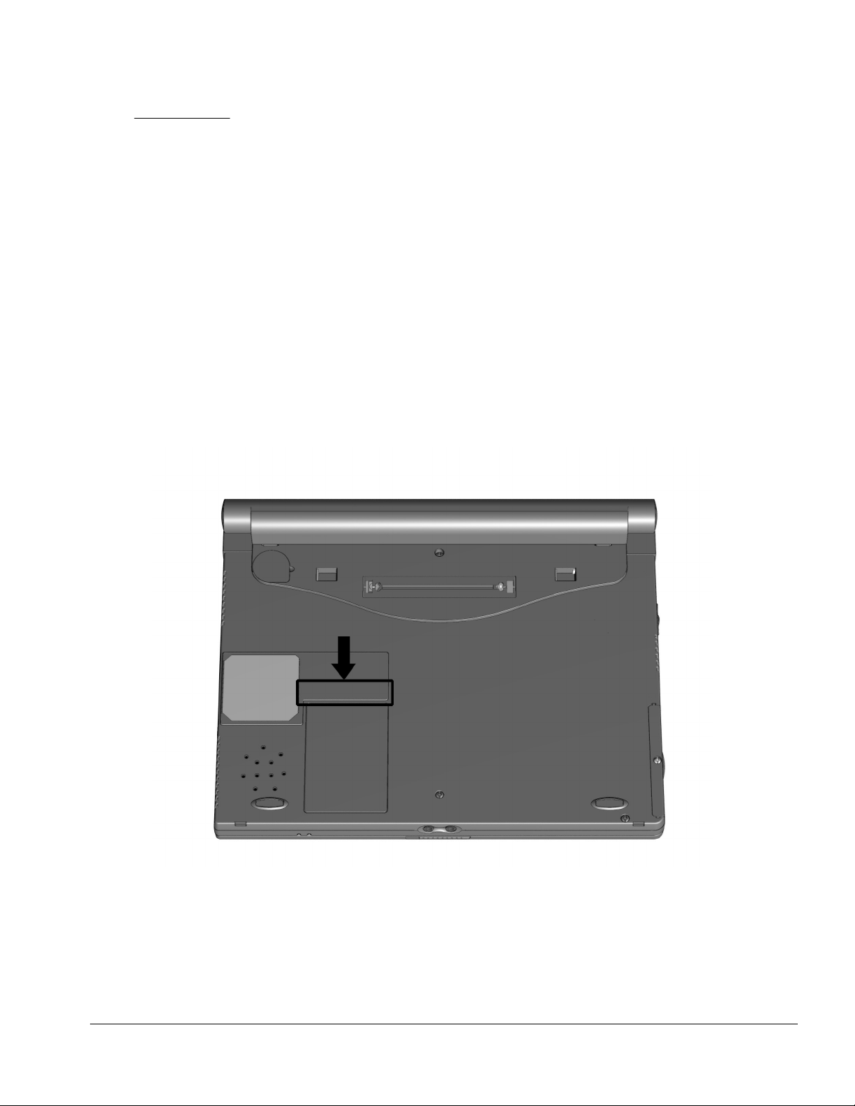
5.1 Serial Number
The computer serial number should be reported to Compaq when requesting
information or ordering spare parts. The serial number is located on the bottom of the
computer (Figure 5-1).
Figure 5-1.
Serial Number Location
Removal and Replacement Procedures 5-1
Page 2

5.2 Disassembly Reference Chart
Use the chart below to determine the section number to be referenced when removing
components from the computer.
5.3 Disconnecting the Computer from the Mobile Expansion Unit
5.4 Disconnecting the Computer
5.5 Preparing the Computer for Disassembly
5.6 Battery Packs
Removing the Battery Pack
Replacing the Battery Pack
5.7 Hard Drives
Removing a Hard Drive
Inserting a Hard Drive
5.8 PC Cards
Removing a PC Card
Inserting a PC Card
5.9 Modem or Modem/NIC Card
5.10 Real Time Clock Battery
5.11 Keyboard
5.12 Memory Expansion
Removing Memory Expansion Boards
Installing Memory Expansion Boards
5.13 Switch Cover
5.14 Display Assembly
5.15 Top Cover with TouchPad
5.16 Voltage Converter Board
5.17 Modem Connector Board
5.18 PC Card Connector
5.19 Processor/System Board Assembly
Figure 5-2.
Disassembly Reference Chart
5-2 Removal and Replacement Procedures
Page 3
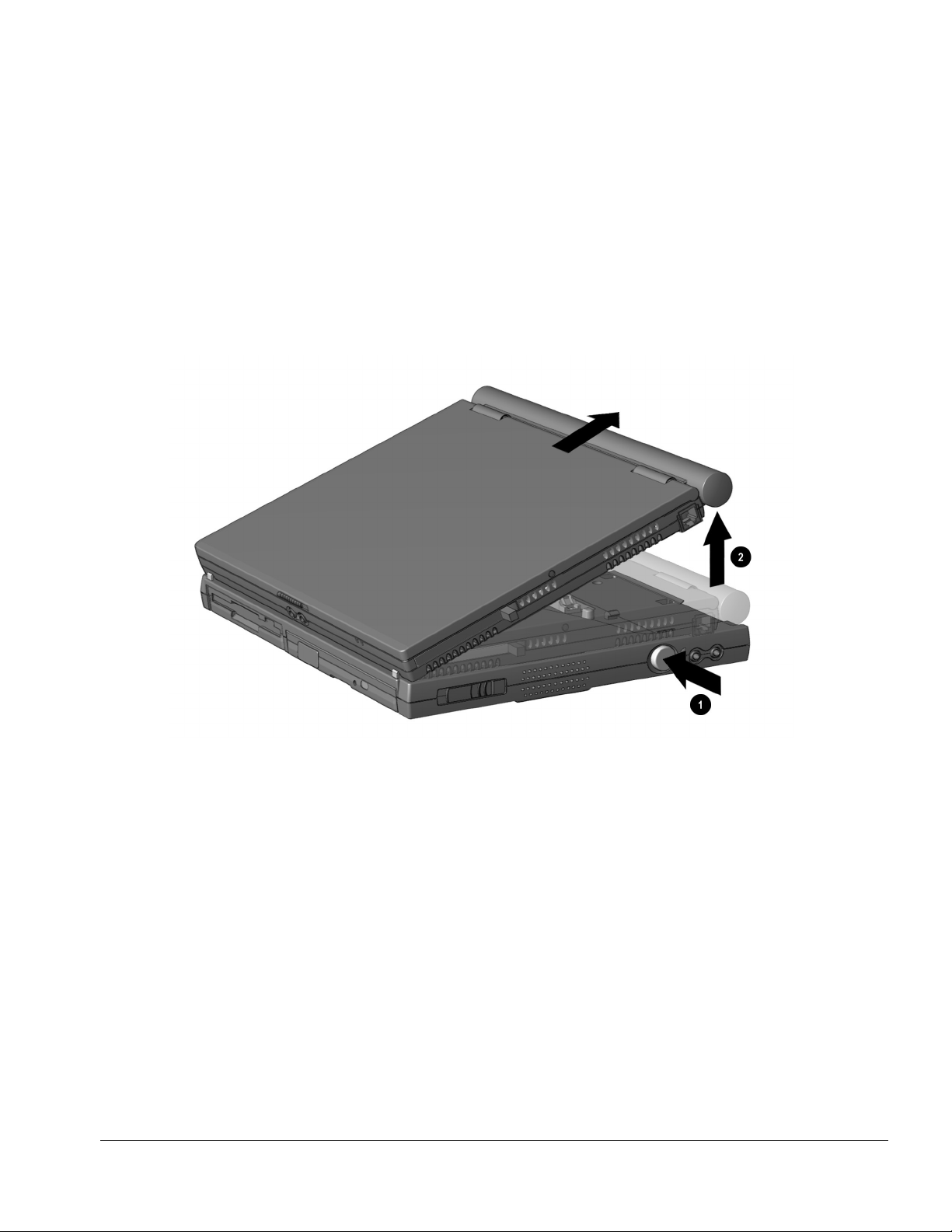
5.3 Disconnecting the Computer from the Mobile
Expansion Unit
1.
Turn off the computer.
2.
Close the display.
3.
Turn off and disconnect all external devices connected to the computer.
4.
On the mobile expansion unit, press the docking release button ➊ to release the
expansion unit from the computer (Figure 5-3).
5.
Lift the rear end of the computer to disconnect it from the computer expansion
➋
connector
6.
Pull the computer away from the mobile expansion unit tabs
.
.
Figure 5-3.
Disconnecting the Computer from the Mobile Expansion Unit
Removal and Replacement Procedures 5-3
Page 4
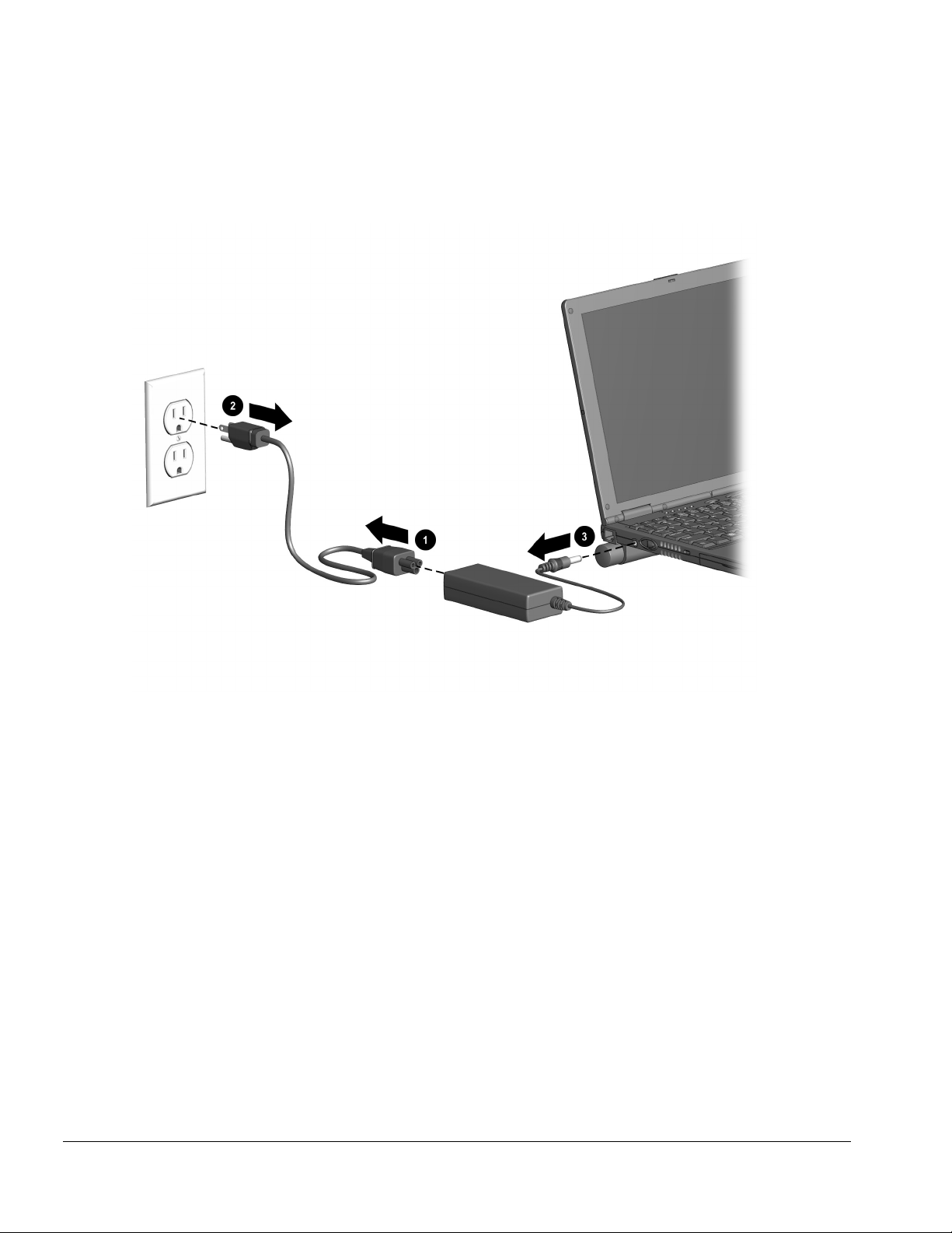
5.4 Disconnecting the Computer
➊
➋
.
(Figure 5-4).
1. Disconnect the AC power cord from the AC adapter
2. Unplug the power cord from the electrical outlet
3. Disconnect the AC adapter from the power connector on the left side of computer
➌
.
Figure 5-4.
5-4 Removal and Replacement Procedures
Disconnecting the Computer
Page 5

5.5 Preparing the Computer for Disassembly
1. Disconnect the computer from the mobile expansion unit.
2. Shut down the computer.
3. Disconnect the AC adapter and all external devices connected to the computer.
4. Remove the battery pack (Section 5.6).
CAUTION:
battery pack before removing and installing internal components can damage the
equipment.
Failure to disconnect the AC Adapter from the computer and to remove the
5. Remove the hard drive (Section 5.7).
6. Remove all PC Cards (Section 5.8).
Removal and Replacement Procedures 5-5
Page 6
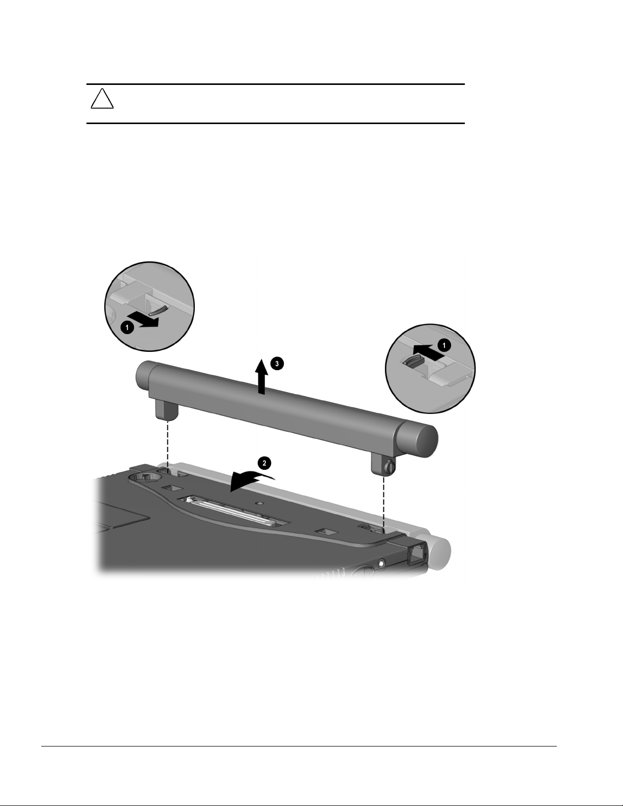
5.6 Battery Packs
WARNING:
!
puncture, or incinerate the battery pack or short the metal contacts. Do not attempt to open
or service the battery pack.
To reduce the risk of injury or damage to the battery pack, do not crush,
Removing the Battery Pack
1.
Shut down the computer.
2.
Turn the computer upside down.
3.
Tilt the battery pack so it lies flat.
4.
Slide in the two battery latches toward each other
5.
Rotate the battery pack 90 degrees toward the computer
➌
pack from the computer
.
➊
(Figure 5-5).
➋
,
and lift up the battery
Figure 5-5.
5-6 Removal and Replacement Procedures
Removing the Battery Pack
Page 7
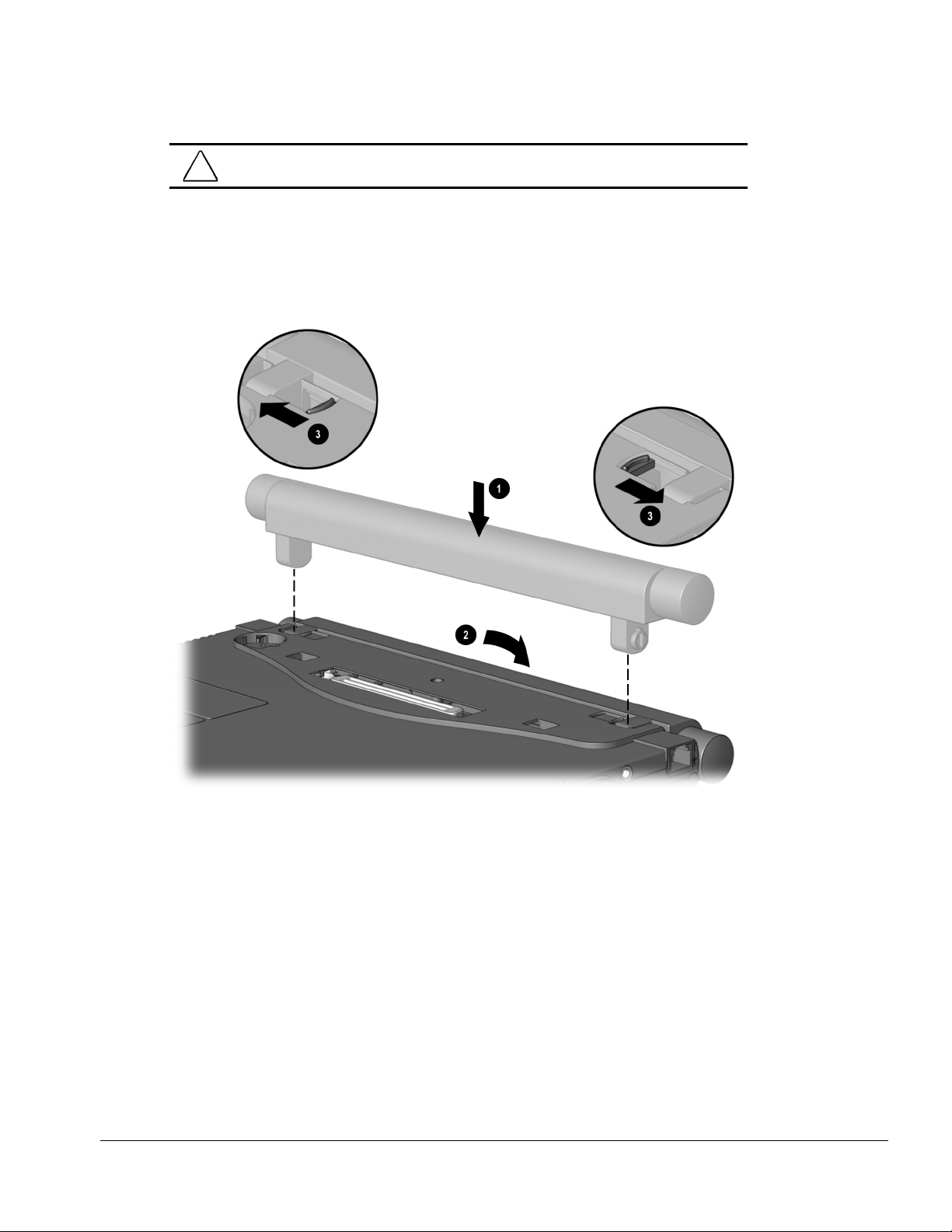
Replacing the Battery Pack
WARNING:
!
computer is fully reassembled.
1.
Turn the computer upside down.
2.
Push the battery pack onto the computer until the contacts connect ➊, and rotate the
battery pack 90 degrees toward the back of the computer
3.
Slide the two battery latches out (away from each other) ➌.
To prevent damage to the computer, do not insert a battery pack until the
➋
(Figure 5-6).
Figure 5-6.
Replacing the Battery Pack
Removal and Replacement Procedures 5-7
Page 8
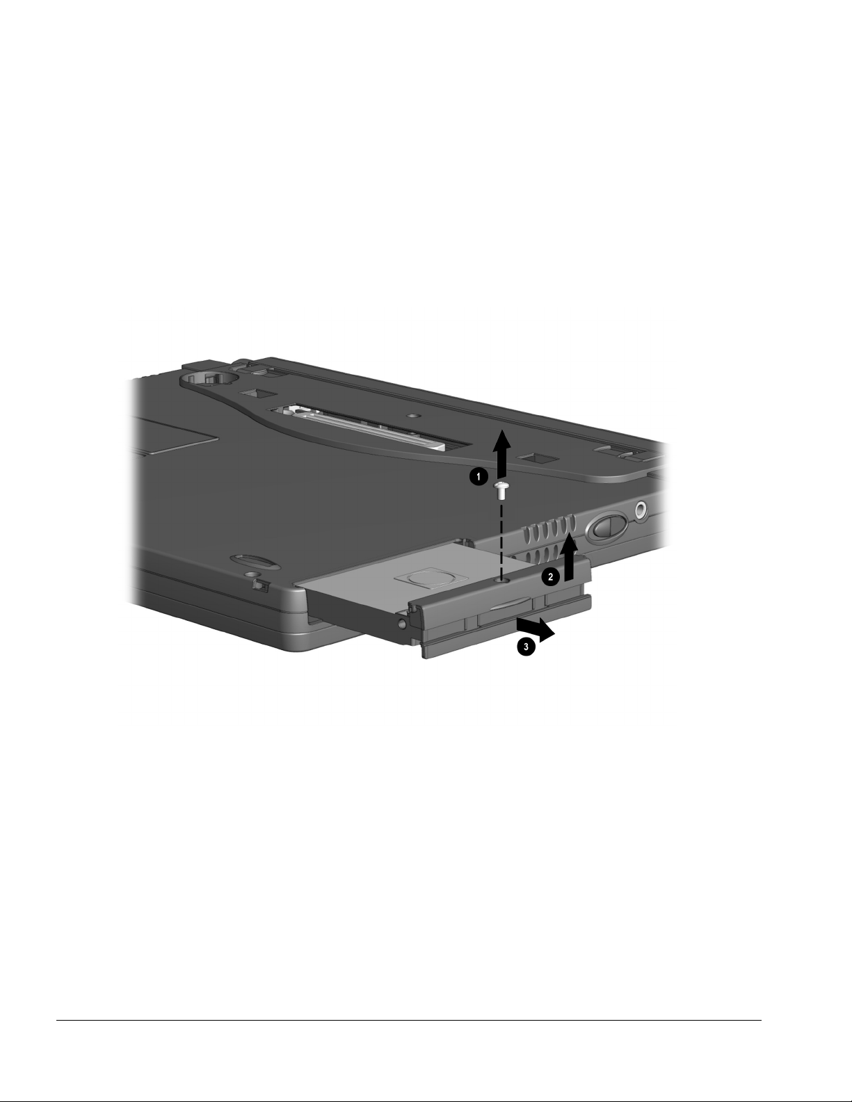
5.7 Hard Drives
Removing a Hard Drive
Before removing a hard drive, back up all information on the hard drive.
1.
Shut down the computer.
2.
Turn the computer upside down.
3.
Remove the hard drive screw
4.
Pull up on the front bezel ➋.
5.
Slide the hard drive out of the bay
➊
(Figure 5-7).
➌
.
Figure 5-7.
5-8 Removal and Replacement Procedures
Removing a Hard Drive
Page 9
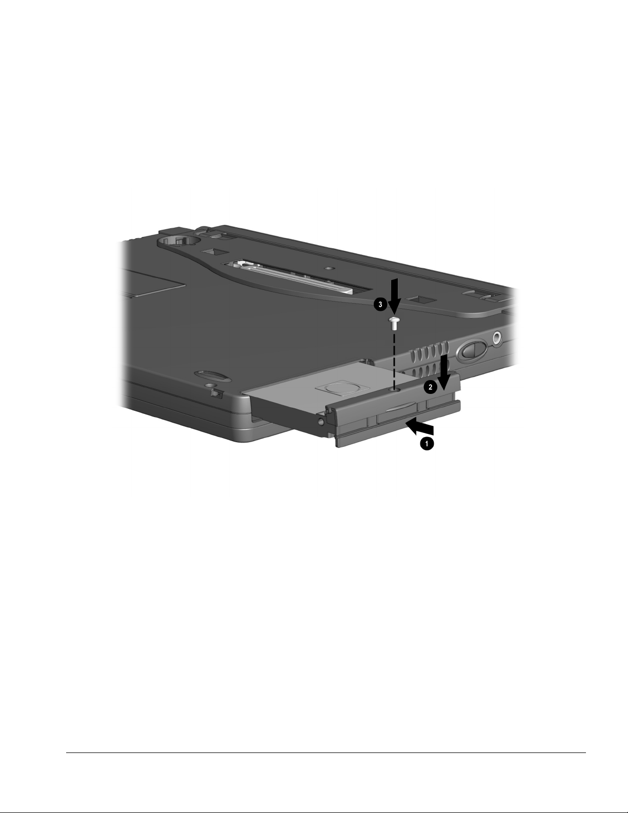
Inserting a Hard Drive
1.
Shut down the computer.
2.
Turn the computer upside down.
3.
Pull the bottom half of the bezel down.
4.
Slide the hard drive into the bay until the connector is seated
5.
Push the front bezel down ➋.
6.
Insert the hard drive screw
➌
.
➊
(Figure 5-8).
Figure 5-8.
Inserting a Hard Drive
Removal and Replacement Procedures 5-9
Page 10

5.8 PC Cards
The procedure for removing PC Cards varies with the operating system being used and
with the kind of PC Card being removed.
In Windows 95 or Windows 98
■
If you insert a PC Card while the computer is on, the computer beeps twice when the
—
card is ready for use.
■
If you remove a PC Card while the computer is on, the computer beeps twice when
the card is removed.
■
When a PC Card is in the system, the PC Card icon displays on the taskbar.
In Windows NT 4.0 with CardWare from Compaq
■
If you insert a PC Card while the computer is on, the computer beeps three times
—
when the card is recognized.
■
If you remove a PC Card while the computer is on, the computer beeps three times
when the card is removed.
■
The PC Card icon displays in the taskbar whether or not a PC Card is in the system.
5-10 Removal and Replacement Procedures
Page 11

Removing a PC Card
First, prepare the system for the removal:
CAUTION:
before removing it may cause loss of data.
■
In Windows 95 or Windows 98
If the computer is on and running Windows 95, failure to stop a PC Card
—If the computer is on, stop the PC Card before
you remove it. To stop a PC Card, select the PC Card icon in the taskbar, then select
the PC Card you want to stop. A message displays when the PC Card can be safely
removed.
■
In Windows NT 4.0 with CardWare provided by Compaq
—If the computer is
on, you must shut it down before removing some PC Cards. Refer to the PC Card
documentation for removal requirements. Second, remove the PC Card:
1.
Press the PC Card eject button ➊ (Figure 5-9).
2.
Gently grasp the card and pull it out ➋.
Figure 5-9.
Removing a PC Card
Removal and Replacement Procedures 5-11
Page 12

Inserting a PC Card
CAUTION:
PC Card into the PC Card slot.
1.
With the connector facing the computer and the label side up, insert the PC Card
To prevent damage to the connectors, use minimal pressure as you insert a
in the slot, aligning the card on the two guide rails inside the PC Card slot
(Figure 5-10).
2.
Gently push the card into the slot until the card is seated.
Figure 5-10.
5-12 Removal and Replacement Procedures
Inserting a PC Card
Page 13

5.9 Modem or Modem/NIC Card
1.
Prepare the computer for disassembly (Section 5.5).
2.
If attached, disconnect the RJ-11 and RJ-45 cables from the computer.
3.
Turn the computer upside down with the front facing forward.
4.
Remove the two screws that secure the modem or modem/NIC card cover to the base
➊
assembly
5.
Lift the front edge of the cover and swing it back
6.
Remove the cover ➌.
(Figure 5-11).
➋
.
Figure 5-11.
Removing the Modem or Modem/NIC Card Cover
Removal and Replacement Procedures 5-13
Page 14

7.
Lift up on the back of the modem or modem/NIC card ➊, and swing it forward to
disconnect it from the system board ➋ (Figure 5-12).
8.
Use the connector removal tool to disconnect all cables connected to the card ➌.
9.
Remove the card.
Figure 5-12.
Removing the Modem or Modem/NIC Card
Reverse the above procedure to install the modem or modem/NIC card.
5-14 Removal and Replacement Procedures
Page 15

5.10 Real Time Clock (RTC) Battery
1.
Prepare the computer for disassembly (Section 5.5).
2.
Turn the computer upside down with the rear panel facing forward.
3.
Remove the RTC battery cover by lifting it at the indentation
4.
Remove the battery from the base enclosure ➋.
5.
Use the connector removal tool to disconnect the RTC battery cable from the system
➌
board
6.
Remove the battery.
.
➊
(Figure 5-13).
Figure 5-13.
Removing the RTC Battery
Reverse the above procedure to install the RTC battery.
Removal and Replacement Procedures 5-15
Page 16

5.11 Keyboard
1.
Prepare the computer for disassembly (Section 5.5).
2.
Press down on each of the three release tabs
(Figure 5-14).
3.
Swing the top edge of the keyboard up and forward
➊
along the top edge of the keyboard
➋
.
Figure 5-14.
5-16 Removal and Replacement Procedures
Releasing the Keyboard
Page 17

4.
Use the connector removal tool to release the keyboard cable from the ZIF connector
➊
(Figure 5-15).
5.
Use the connector removal tool to disconnect the keyboard cable
6.
Remove the keyboard.
➋
.
Figure 5-15.
Disconnecting the Keyboard Cable
Reverse the above procedure to install the keyboard.
Removal and Replacement Procedures 5-17
Page 18

5.12 Memory Expansion
Removing the Memory Expansion Board
NOTE:
WARNING:
installing a memory expansion board can damage the equipment and expose you to
the risk of electrical shock.
CAUTION:
beginning this procedure, ensure that you are properly grounded. For more
information, refer to “Preventing Electrostatic Damage” in Chapter 4.
There is only one memory expansion slot in the computer. Before upgrading
Failure to unplug the power cord and to remove the battery pack before
Electrostatic discharge (ESD) can damage electronic components. Before
memory, you must remove the memory board that came with the computer.
1.
To remove the memory board, pull away the plastic retention clips on each side of
➊
the memory board
2.
Lift the edge of the memory expansion board and slide it gently out of the memory
expansion slot at a 45-degree angle
3.
If applicable, turn back the memory insulator.
4.
Place the removed memory expansion board in an electrostatic-safe container.
. The memory expansion board tilts upward (Figure 5-16).
➋
.
Figure 5-16.
5-18 Removal and Replacement Procedures
Removing the Memory Board
Page 19

Installing the Memory Expansion Board
1.
To add a memory board, insert the memory expansion board into the empty memory
➊
expansion slot at a 45-degree angle
seated while tilted (Figure 5-17).
NOTE:
All memory expansion boards supported by the computer are keyed (notched) to
ensure correct positioning.
2.
Push the memory expansion board down until the plastic retention clips ➋ snap into
place.
3.
Replace the memory insulator, if applicable.
4.
Replace the keyboard by gently pressing down on the top of the keyboard until it
clicks into place.
. Then slide it gently into place until it is
Figure 5-17.
Installing the Memory Board
Removal and Replacement Procedures 5-19
Page 20

5.13 Switch Cover
1.
Prepare the computer for disassembly (Section 5.5).
2.
Remove the keyboard (Section 5.11).
3.
Position the computer so the rear panel faces forward.
4.
Remove the two screws from the rear panel of the computer that secure the switch
cover to the base assembly (Figure 5-18).
Figure 5-18.
Removing the Switch Cover Screws
5-20 Removal and Replacement Procedures
Page 21

5.
Position the computer so the front faces forward.
6.
Open the computer as far as it will open.
7.
Swing the back edge of the switch cover forward
8.
When the switch cover disengages from the base assembly, remove the cover
➊
(Figure 5-19).
➋
.
Figure 5-19.
Removing the Switch Cover
Reverse the above procedure to install the switch cover.
Removal and Replacement Procedures 5-21
Page 22

5.14 Display Assembly
1.
Prepare the computer for disassembly (Section 5.5).
2.
Remove the keyboard (Section 5.11).
3.
Remove the switch cover (Section 5.13).
4.
Use the connector removal tool to disconnect the inverter cable ➊ from the system
board (Figure 5-20)
5.
Use the connector removal tool to disconnect the microphone cable
➋
cable
6.
Remove display screw covers from the hinges connecting the display assembly to
from the system board.
the base assembly.
7.
Remove the four screws (two on each hinge)
the base assembly.
NOTE:
When these four screws are removed, the display assembly is unsupported.
Make sure to support the display assembly when removing these screws.
8.
Remove the display assembly.
.
➋
and the video
➌
that secure the display assembly to
Figure 5-20.
Removing the Display Assembly
Reverse the above procedure to install the display.
5-22 Removal and Replacement Procedures
Page 23

5.15 Top Cover with TouchPad
NOTE:
The power button and infrared lens are easily dislodged when the top cover is
removed. Make note of their location and orientation before removing the top cover.
1.
Prepare the computer for disassembly (Figure 5.5).
2.
Remove the keyboard (Section 5.11).
3.
Remove the switch cover (Section 5.13).
4.
Remove the display assembly (Section 5.14).
5.
Turn the computer upside down with the rear panel facing forward.
6.
Remove the seven screws from the bottom of the computer (Figure 5-21).
7.
Remove the four screws from the back of the computer.
Figure 5-21.
Removing the Top Cover Screws
Removal and Replacement Procedures 5-23
Page 24

8.
Turn the computer right side up with the front facing forward.
9.
Use the connector removal tool to disconnect the TouchPad cable
➊
from the system
board (Figure 5-22).
10.
Press in on the front of the top cover at the highlighted area ➋, and swing the front
➌
edge of the cover up and away from the base assembly
11.
Remove the top cover.
.
.
Figure 5-22.
Removing the Top Cover
Reverse the above procedure to install the top cover. Make sure the power switch and
infrared lens are replaced in their appropriate locations before attempting to install the
top cover.
5-24 Removal and Replacement Procedures
Page 25

5.16 Voltage Converter Board
NOTE:
When removing the voltage converter board from the system board, be careful of
the connectors on the right side of the voltage converter board.
1.
Prepare the computer for disassembly (Section 5.5).
2.
Remove the keyboard (Section 5.11).
3.
Remove the switch cover (Section 5.13).
4.
Remove the display assembly (Section 5.14).
5.
Remove the top cover (Section 5.15).
6.
Remove the two screws ➊ that secure the voltage converter board to the system
board (Figure 5-23).
7.
Lift up the left side of the voltage converter ➋ until it clears the left edge of the base
assembly.
8.
Pull the voltage converter board to the left to disconnect it from the system board ➌.
Figure 5-23.
Removing the Voltage Converter Board
Reverse the above procedure to install the voltage converter board. Make sure to attach
the connectors on the right side of the board to the system board first.
Removal and Replacement Procedures 5-25
Page 26

5.17 Modem Connector Board
1.
Prepare the computer for disassembly (Section 5.5).
2.
Remove the modem or modem/NIC card (Section 5.9).
3.
Remove the keyboard (Section 5.11).
4.
Remove the switch cover (Section 5.13).
5.
Remove the display assembly (Section 5.14).
6.
Remove the top cover (Section 5.15).
7.
Remove the two screws that secure the modem connector board
board (Figure 5-24).
8.
Lift up on the modem connector board ➋ to disconnect it from the system board.
9.
Remove the modem connector board.
➊
to the system
Figure 5-24.
Removing the Modem Connector Board
Reverse the above procedure to install the modem connector board.
5-26 Removal and Replacement Procedures
Page 27

NOTE:
When installing the modem connector board, make sure the fan cable is routed
between the connector and the modem connector area (Figure 5-25). Do not route the
cable next to the heat sink.
Figure 5-25.
Routing the Fan Cable
Removal and Replacement Procedures 5-27
Page 28

5.18 PC Card Assembly
IMPORTANT:
There are different-sized screws securing the PC Card assembly to the
system board. Make note of the location of these screws.
1.
Prepare the computer for disassembly (Section 5.5).
2.
Remove the modem or modem/NIC card (Section 5.9).
3.
Remove the keyboard (Section 5.11).
4.
Remove the switch cover (Section 5.13).
5.
Remove the display assembly (Section 5.14).
6.
Remove the top cover (Section 5.15).
7.
Remove the modem connector board (Section 5.17).
8.
Remove the two silver screws
.
26)
9.
Remove the black screw ➋ securing the front of the PC Card assembly to the base
➊
on the left side of the PC Card assembly (Figure 5-
assembly.
10.
Lift the left side of the PC Card assembly ➌ to disconnect it from the system board.
Figure 5-26.
Removing the PC Card Assembly
Reverse the above procedures when installing the PC Card assembly.
IMPORTANT:
Be sure to route the audio and light board cables between the PC Card
assembly and the base plastic. Do not route the cables near the heat sink.
5-28 Removal and Replacement Procedures
Page 29

5.19 System Board
IMPORTANT:
There are different-sized screws securing the system board to the base
enclosure. Make note of the location of these screws. Also, when the system board is
removed, components of the base enclosure may come loose. Note the location and
orientation of all base enclosure components.
1.
Prepare the computer for disassembly (Section 5.5).
2.
Remove the RTC battery (Section 5.10).
3.
Remove the keyboard (Section 5.11).
4.
Remove the switch cover (Section 5.13).
5.
Remove the display assembly (Section 5.14).
6.
Remove the top cover (Section 5.15).
7.
Remove the modem connector board (Section 5.17).
8.
Remove the PC Card assembly (Section 5.18).
9.
Position the computer so the front faces forward.
10.
Use the connector removal tool to disconnect the left battery terminal cable ➊, right
➋
battery cable
, fan cable ➌, LED cable ➍, and speaker cable ! (Figure 5-27)
Figure 5-27.
Disconnecting Cables from the System Board
Removal and Replacement Procedures 5-29
Page 30

11.
Remove the two screws from the back of the computer that secures the system board
➊
to the base enclosure
12.
Remove the silver screw from the heat sink ➋.
13.
Remove the black screws from around the fan ➌, around the USB port ➌, and
around the battery cable in the upper left of the board
14.
Lift up the rear edge of the system board.
15.
Remove the system board.
(Figure 5-28).
➌
.
Figure 5-28.
Removing the System Board
Reverse the above procedure when installing the system board. Make sure to replace
all components of the base enclosure into their appropriate locations.
5-30 Removal and Replacement Procedures
 Loading...