

Page 1

PageWriter 100, 200 and 300 Series Cardiographs
M1770A, M1771A, and M1772A
Mobile Cart M1705B
Service Manual
+
+33DUW1R0
3ULQWHGLQ86$2FWREHU
(GLWLRQ
October 22, 1998 3:00 pm DRAFT
&RS\ULJKW
+HZOHWW3DFNDUG&RPSDQ\
3ULQWHGLQ86$
Page 2

Notice
WARNING
0Notice
The information in this document is subj ect to change without notice.
Hewlett-Packard makes no warranty of any kind with regard to this material, includ ing,
but not limited to, the implied warranties of merchantability and fitness for a particular
purpose. Hewlett-Packard shall not be liable for errors contained herein or for incidental
or consequential damages in conn ection with the furnishing, performance, or use of this
material.
This document contains or refers to proprietary information which is protected by
copyright. All rights are reserved. No part of this document may be photocopied,
reproduced, or translated to another language without the prior written consent of HewlettPackard Company.
Responsibility of the Manufacturer
Hewlett-Packard only considers itself responsible for any effects on safety, reliability and
performance of the equipment if all the following are true:
• Assembly operations, extensions, re-adjustments, modifications or repairs are done by
persons authorized by Hewlett-Packard.
• The electrical installation of the relevant room complies with the IEC or national requirements.
• The instrument is used according to the instructions for use presented in this manual.
As with all electronic equipment, radio frequency interference between this
cardiograph and any existing RF transmitting or receiving equipment at the
installation site, including electrosurgical equipment, should be evaluated
carefully and any limitations noted before the equipment is placed in service.
Monitoring during electrosurgery should not be attempted and monitoring
electrodes should be removed from the patient to preclude the possibility of
burns. Radio frequency generation from electrosurgical equipment and close
proximity transmitters may seriously degrade cardiograph performance. HewlettPackard assumes no liability for failures resulting from RF interference between
HP medical electronics and any radio frequency generating equipment at levels
exceeding those established by applicable standards.
ii
Page 3

Notice
CAUTION
CAUTION
Like all electronic devices, this cardiograph is susceptible to electrostatic discharge
(ESD). Electrostatic discharge typically occurs when electrostatic energy is transferred to
the patient, the electrodes, or the cardiograph. ESD may result in ECG artifact that may
appear as narrow spikes on the cardiograph display or on the printed report. When ESD
occurs, the cardiograph’s ECG interpretation may be inconsistent with the physician’s
interpretation.
ESD discharges to exposed metal on the rear of the cardiograph can occasionally cause an
error message to appear on the cardiograph display. The cardiograph returns to normal
operation after turning the power off, then on again.
The data transmission cable must have a suppression device attached to assure the
cardiograph’s compliance with the European Radiated Emissions Standard found in
CISPR 11. If your data transmission cable does not include a suppression device,
compliance can be achieved by attaching one of the following suppression devices to the
cable, near the cardiograph:
part number 0443164251 Fair-Rite Products Corporat ion
P. O. Box J
One Commercial Row
Wallkill, Ne w York 12589
telephone: (914) 895-2055
FAX: (914)895-2629
or
Euro-Schaffner, S. A.
1 B Avenue de Suisse - BP 16
68311 Illzach Cedex, France
telephone: 33-8-931-0400
FAX: 33-8-931-0401
part number 28B2025-0A0 Steward
East 36th Street
P. O. Box 510
Chattanooga, TN 37401
telephone: (615) 867-4100
FAX: (615) 867-4102
or
Steward EMC, S.A.
Rue Fritz-Couvoisier 40
Ch-2300 La Chaux-de-Fonds
Switzerland
telephone: 41-39-282-387
Fax: 41-39-280-277
This is to certify that this equipment is in accordance with the Radio Interference
Requirements of the EMC Directive.
iii
Page 4

Notice
Warranty
Hewlett-Packard warrants this medical product against defects in materials and
workmanship for a period of three years in certain geographics, or one year with onsite
support.
If Hewlett-Packard receives notice of such defects during the warranty period, HewlettPackard shall, at its option, either repair or replace hardware products which prove to be
defective.
Hewlett-Packard software and firmware products that are designated by Hewlett-Packard
for use with a hardware product, when properly installed on that hardware product, are
warranted not to fail to execute their programming instructions due to defect s during the
warranty period. Hewlett-Packard shall repair or replace software media and firmware that
do not execute their programming instructions due to such defects. Hewlett-Packard does
not warrant that the operation of the software, firmware, or hardware shall be
uninterrupted or error free.
If Hewlett-Packard is unable, within a reasonable time, to repair or replace any product to
a condition as warranted, Buyer shall be entitled to a refund of the purchase upon return of
the product to Hewlett-Packard.
Limitation of Warranty
The foregoing warranty shall not apply to defects resulting from any of the following:
1. Improper or inadequate maintenance by Buyer.
2. Buyer-supplied software or interfacing.
3. Unauthorized modification or misuse.
4. Operation outside of the environmental specifications for the product.
5. Improper site preparation and maintenance.
THE WARRANTY SET FORTH ABOVE IS EXCLUSIVE AND NO OTHER
WARRANTY, WHETHER WRITTEN OR ORAL, IS EXPRESSED OR IMPLIED.
HEWLETT-PACKARD SPECIFICALLY DISCLAIMS THE IMPLIED WARRANTIES
OF MERCHANTABILITY AND FITNESS FOR A PARTICULAR PURPOSE.
iv
Page 5

Notice
Printing History
October 1994 Edition 1
May 1996 Edition 2
October 1998 Edition 3
v
Page 6
Safety Summary
0Safety Summary
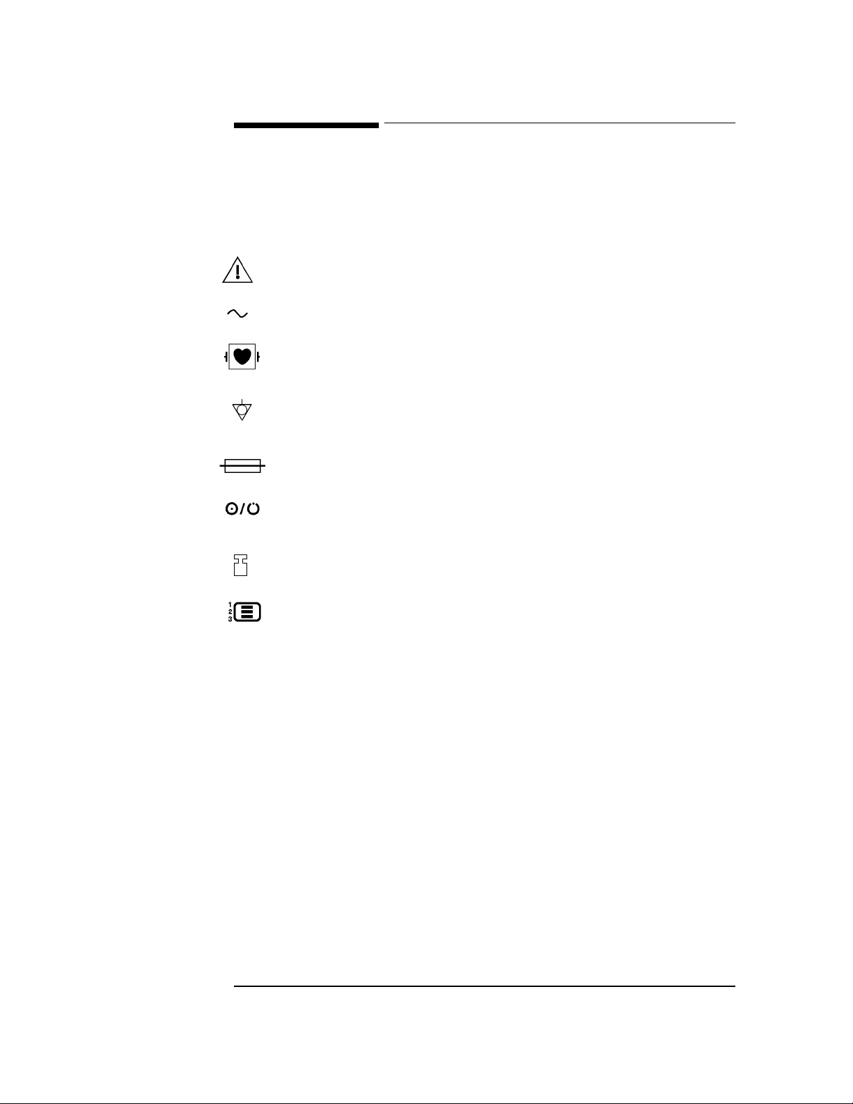
Safety Symbols Marked on the Cardiograph
The following symbols are used on the cardiograph or the cart:
Caution - See operating instructions
Alternating current.
Meets IEC type CF leakage current requirements and is defibrillator
protected. (Isolated ECG input.)
Equipotential (identifies independent protective earth conductor to the
cardiograph).
Fuse.
Indicates power control for cardiograph.
Hz Indicates operating frequency in cycles per second.
The maximum weight that the cart can hold
Displays the configuration menu on the PageWriter
200/200/300pi.
Please see Chapter 2, “Performance Verification and Maintenance,” for safety
requirements that apply to the cardiograph.
vi
Page 7

Conventions Used in This Manual
WARNING
CAUTION
NOTE
0Conventions Used in This Manual
Warning statements describe conditions or actions that can result in personal
injury or loss of life.
Caution statements describe conditions or actions that can result in damage to the
equipment or software.
Notes contain additional information on cardiograph usage.
TEXT represents the labels that appear on the display.
.H\
Softkey
represents keys on the key panel.
represents the temporary key labels that appear on the display.
vii
Page 8

Preface
0Preface
This manual contains service information for the Hewlett-Packard M1 770A pageWriter
300pi, PageWriter 200i, M1771A PageWriter 200, and M1772A PageWriter 100
cardiographs. The information and procedures in this manual apply to all models unless
otherwise specified.
This manual is organized as follows:
• Chapter 1 — I n troduction. Contains a general description of the cardiographs, lists of
technical specifications, and lists of accessories and options.
• Chapter 2 — Performance Verification and Maintenance. Explains how to check the
cardiograph’s performance using built-in self-tests, and lists maintenance procedures and
safety requirements that apply to the cardiograph.
• Chapter 3 — Theory of Operation. Provides an overview of how the cardiograph
works and describes the operation of the m a jor subassemblies.
• Chapter 4 — Troubleshooting. Contains procedures and error codes to aid the service
person in localizing faults to a replaceable subassembly.
• Chapter 5 — Removal and Replacement. Contains procedures for removing and
replacing each of the cardiograph’s major subassemblies.
• Chapter 6 — Parts List. Lists part numbers for the cardiog raph’s replaceable parts, an d
provides assembly drawings.
• Appendix A — Connector Pin Assign ment s. Identifies and defines the signals
assigned to the subassembly interconnections.
• Index.
viii
Page 9

Contents
Notice. . . . . . . . . . . . . . . . . . . . . . . . . . . . . . . . . . . . . . . . . . . . . . . . . . . . . . . . . . . . . . . . . . . . . . . . . . . . . .ii
Responsibility of the Manufacturer . . . . . . . . . . . . . . . . . . . . . . . . . . . . . . . . . . . . . . . . . . . . . . . . . .ii
Warranty . . . . . . . . . . . . . . . . . . . . . . . . . . . . . . . . . . . . . . . . . . . . . . . . . . . . . . . . . . . . . . . . . . . . . iv
Limitation of Warranty . . . . . . . . . . . . . . . . . . . . . . . . . . . . . . . . . . . . . . . . . . . . . . . . . . . . . . . . . . iv
Safety Summary . . . . . . . . . . . . . . . . . . . . . . . . . . . . . . . . . . . . . . . . . . . . . . . . . . . . . . . . . . . . . . . . . . . vi
Safety Symbols Marked on the Cardiograph. . . . . . . . . . . . . . . . . . . . . . . . . . . . . . . . . . . . . . . . . . vi
Conventions Used in This Manual . . . . . . . . . . . . . . . . . . . . . . . . . . . . . . . . . . . . . . . . . . . . . . . . . . . .vii
Preface . . . . . . . . . . . . . . . . . . . . . . . . . . . . . . . . . . . . . . . . . . . . . . . . . . . . . . . . . . . . . . . . . . . . . . . . . viii
1. Introduction
PageWriter 100, 200, 200i, and 300pi Series Cardiographs . . . . . . . . . . . . . . . . . . . . . . . . . . . . . . . . 1-1
M1705B Cart . . . . . . . . . . . . . . . . . . . . . . . . . . . . . . . . . . . . . . . . . . . . . . . . . . . . . . . . . . . . . . . . . 1-3
Transmission and Storage, Option #A05 . . . . . . . . . . . . . . . . . . . . . . . . . . . . . . . . . . . . . . . . . . . 1-3
Inquiries . . . . . . . . . . . . . . . . . . . . . . . . . . . . . . . . . . . . . . . . . . . . . . . . . . . . . . . . . . . . . . . . . . . . . . . . 1-3
Specification Data . . . . . . . . . . . . . . . . . . . . . . . . . . . . . . . . . . . . . . . . . . . . . . . . . . . . . . . . . . . . . . . . 1-3
Sampling Characteristics of Cardiograph . . . . . . . . . . . . . . . . . . . . . . . . . . . . . . . . . . . . . . . . . . 1-4
Options and Accessories . . . . . . . . . . . . . . . . . . . . . . . . . . . . . . . . . . . . . . . . . . . . . . . . . . . . . . . . . . . 1-8
PageWriter 100, 200, 200i, and 300pi Cardiographs. . . . . . . . . . . . . . . . . . . . . . . . . . . . . . . . . . 1-8
Country/Region Options . . . . . . . . . . . . . . . . . . . . . . . . . . . . . . . . . . . . . . . . . . . . . . . . . . . 1-8
Standard Accessories . . . . . . . . . . . . . . . . . . . . . . . . . . . . . . . . . . . . . . . . . . . . . . . . . . . . . 1-12
2. Performance Verification and Maintenance
Introduction . . . . . . . . . . . . . . . . . . . . . . . . . . . . . . . . . . . . . . . . . . . . . . . . . . . . . . . . . . . . . . . . . . . . . 2-1
Performance Verification . . . . . . . . . . . . . . . . . . . . . . . . . . . . . . . . . . . . . . . . . . . . . . . . . . . . . . . . . . . 2-1
Visual Inspection and Power On Self Test . . . . . . . . . . . . . . . . . . . . . . . . . . . . . . . . . . . . . . . . . 2-2
Extended Self-test . . . . . . . . . . . . . . . . . . . . . . . . . . . . . . . . . . . . . . . . . . . . . . . . . . . . . . . . . . . . . 2-2
Internal Circuitry Testing of PageWriter 100 . . . . . . . . . . . . . . . . . . . . . . . . . . . . . . . . . . . 2-2
Internal Circuitry Testing of PageWriter 200/200i/300pi . . . . . . . . . . . . . . . . . . . . . . . . . . 2-4
Memory Test . . . . . . . . . . . . . . . . . . . . . . . . . . . . . . . . . . . . . . . . . . . . . . . . . . . . . . . . . . . . 2-5
How to Read the Extended Self-Test Report . . . . . . . . . . . . . . . . . . . . . . . . . . . . . . . . . .2-11
Display Test (PageWriter 200/200i/300pi only) . . . . . . . . . . . . . . . . . . . . . . . . . . . . . . . . . . . . . 2-12
Indicator Light Test (PageWriter 100 only). . . . . . . . . . . . . . . . . . . . . . . . . . . . . . . . . . . . . . . . . 2-12
Printer Test . . . . . . . . . . . . . . . . . . . . . . . . . . . . . . . . . . . . . . . . . . . . . . . . . . . . . . . . . . . . . . . . . 2-12
Keyboard Tests . . . . . . . . . . . . . . . . . . . . . . . . . . . . . . . . . . . . . . . . . . . . . . . . . . . . . . . . . . . . . . 2 -13
PageWriter 200/200i/300pi Keyboard Test . . . . . . . . . . . . . . . . . . . . . . . . . . . . . . . . . . . . 2-13
PageWriter 100 Keyboard Test . . . . . . . . . . . . . . . . . . . . . . . . . . . . . . . . . . . . . . . . . . . . . 2-13
ECG Simulation . . . . . . . . . . . . . . . . . . . . . . . . . . . . . . . . . . . . . . . . . . . . . . . . . . . . . . . . . . . . . 2-14
Changing the Default Operating Language (200/200i/300pi Only) . . . . . . . . . . . . . . . . . . . . . . . . . 2-16
Resetting the Cardiograph to the Factory Default State . . . . . . . . . . . . . . . . . . . . . . . . . . . . . . . . . . 2-17
Resetting the PageWriter 200/200i/300pi . . . . . . . . . . . . . . . . . . . . . . . . . . . . . . . . . . . . . . . . . . 2-17
Resetting the PageWriter 100 . . . . . . . . . . . . . . . . . . . . . . . . . . . . . . . . . . . . . . . . . . . . . . . . . . . 2-17
Preventive Maintenance . . . . . . . . . . . . . . . . . . . . . . . . . . . . . . . . . . . . . . . . . . . . . . . . . . . . . . . . . . . 2-18
Care and Cleaning . . . . . . . . . . . . . . . . . . . . . . . . . . . . . . . . . . . . . . . . . . . . . . . . . . . . . . . . . . . 2-18
Cleaning the Cardiograph . . . . . . . . . . . . . . . . . . . . . . . . . . . . . . . . . . . . . . . . . . . . . . . . . 2-18
Cleaning the Keyboard Overlay . . . . . . . . . . . . . . . . . . . . . . . . . . . . . . . . . . . . . . . . . . . . 2 -19
Cleaning the Digital Array Printhead and Paper Sensor . . . . . . . . . . . . . . . . . . . . . . . . . . 2-20
ix
Page 10

Cleaning the Electrodes and Cables . . . . . . . . . . . . . . . . . . . . . . . . . . . . . . . . . . . . . . . . . 2-21
Caring for the Battery . . . . . . . . . . . . . . . . . . . . . . . . . . . . . . . . . . . . . . . . . . . . . . . . . . . . . . . . . . . . 2-22
Storing the Battery . . . . . . . . . . . . . . . . . . . . . . . . . . . . . . . . . . . . . . . . . . . . . . . . . . . . . . . . . . . 2-22
Safety Tests . . . . . . . . . . . . . . . . . . . . . . . . . . . . . . . . . . . . . . . . . . . . . . . . . . . . . . . . . . . . . . . . . 2-23
PageWriter 100, 200/200i, and 300pi Series Performance Verification Matrix . . . . . . . . . . . . . . . . 2-24
3. Theory of Operation
Operational Overview . . . . . . . . . . . . . . . . . . . . . . . . . . . . . . . . . . . . . . . . . . . . . . . . . . . . . . . . . . . . . 3-1
ECG Data Path. . . . . . . . . . . . . . . . . . . . . . . . . . . . . . . . . . . . . . . . . . . . . . . . . . . . . . . . . . . . . . . . 3-1
Power-on and Power-off Sequences . . . . . . . . . . . . . . . . . . . . . . . . . . . . . . . . . . . . . . . . . . . . . . . 3-1
Power-on . . . . . . . . . . . . . . . . . . . . . . . . . . . . . . . . . . . . . . . . . . . . . . . . . . . . . . . . . . . . . . . 3-1
Power-off . . . . . . . . . . . . . . . . . . . . . . . . . . . . . . . . . . . . . . . . . . . . . . . . . . . . . . . . . . . . . . . 3-2
Circuit Descriptions . . . . . . . . . . . . . . . . . . . . . . . . . . . . . . . . . . . . . . . . . . . . . . . . . . . . . . . . . . . . . . . 3-2
The Patient Cable . . . . . . . . . . . . . . . . . . . . . . . . . . . . . . . . . . . . . . . . . . . . . . . . . . . . . . . . . . . . . . . . 3-3
CPU Assembly . . . . . . . . . . . . . . . . . . . . . . . . . . . . . . . . . . . . . . . . . . . . . . . . . . . . . . . . . . . . . . . . . . 3-4
CPU/System Oscillator . . . . . . . . . . . . . . . . . . . . . . . . . . . . . . . . . . . . . . . . . . . . . . . . . . . . . . . . . 3-5
System Gate Array/Real-Time Crystal . . . . . . . . . . . . . . . . . . . . . . . . . . . . . . . . . . . . . . . . . . . . . 3-5
ECG Front End Control . . . . . . . . . . . . . . . . . . . . . . . . . . . . . . . . . . . . . . . . . . . . . . . . . . . 3-5
Interrupt Control . . . . . . . . . . . . . . . . . . . . . . . . . . . . . . . . . . . . . . . . . . . . . . . . . . . . . . . . . 3-5
DMA for ECG Data . . . . . . . . . . . . . . . . . . . . . . . . . . . . . . . . . . . . . . . . . . . . . . . . . . . . . . 3-6
DMA for LCD Data . . . . . . . . . . . . . . . . . . . . . . . . . . . . . . . . . . . . . . . . . . . . . . . . . . . . . . 3-6
System Reset Circuitry . . . . . . . . . . . . . . . . . . . . . . . . . . . . . . . . . . . . . . . . . . . . . . . . . . . . 3-6
Watch-dog Circuitry . . . . . . . . . . . . . . . . . . . . . . . . . . . . . . . . . . . . . . . . . . . . . . . . . . . . . . 3-6
Real-Time Clock . . . . . . . . . . . . . . . . . . . . . . . . . . . . . . . . . . . . . . . . . . . . . . . . . . . . . . . . . 3-6
DRAM RAS and CAS Generation and Refresh . . . . . . . . . . . . . . . . . . . . . . . . . . . . . . . . . 3-6
NVRAM Interface . . . . . . . . . . . . . . . . . . . . . . . . . . . . . . . . . . . . . . . . . . . . . . . . . . . . . . . . 3-7
Keyboard Interface. . . . . . . . . . . . . . . . . . . . . . . . . . . . . . . . . . . . . . . . . . . . . . . . . . . . . . . . 3-7
Display Control for PageWriter 20 and 300 Series . . . . . . . . . . . . . . . . . . . . . . . . . . . . . . . 3-7
NVRAM . . . . . . . . . . . . . . . . . . . . . . . . . . . . . . . . . . . . . . . . . . . . . . . . . . . . . . . . . . . . . . . . . . . . 3-7
ECG Front End . . . . . . . . . . . . . . . . . . . . . . . . . . . . . . . . . . . . . . . . . . . . . . . . . . . . . . . . . . . . . . . 3-7
DRAM . . . . . . . . . . . . . . . . . . . . . . . . . . . . . . . . . . . . . . . . . . . . . . . . . . . . . . . . . . . . . . . . . . . . . 3-7
ROM-1 and ROM-2 Address Space . . . . . . . . . . . . . . . . . . . . . . . . . . . . . . . . . . . . . . . . . . . . . . . 3-7
Printer Gate Array/SRAM . . . . . . . . . . . . . . . . . . . . . . . . . . . . . . . . . . . . . . . . . . . . . . . . . . . . . . 3-7
Motor Driver . . . . . . . . . . . . . . . . . . . . . . . . . . . . . . . . . . . . . . . . . . . . . . . . . . . . . . . . . . . . . . . . . 3-8
Analog/Digital Converter . . . . . . . . . . . . . . . . . . . . . . . . . . . . . . . . . . . . . . . . . . . . . . . . . . . . . . . 3-8
Thermal Printhead . . . . . . . . . . . . . . . . . . . . . . . . . . . . . . . . . . . . . . . . . . . . . . . . . . . . . . . . . . . . 3-8
System Expansion Connector . . . . . . . . . . . . . . . . . . . . . . . . . . . . . . . . . . . . . . . . . . . . . . . . . . . . 3-8
Power Supply . . . . . . . . . . . . . . . . . . . . . . . . . . . . . . . . . . . . . . . . . . . . . . . . . . . . . . . . . . . . . . . . . . . 3-9
Voltage Selector . . . . . . . . . . . . . . . . . . . . . . . . . . . . . . . . . . . . . . . . . . . . . . . . . . . . . . . . . . . . . . 3-9
Primary Line Fuses . . . . . . . . . . . . . . . . . . . . . . . . . . . . . . . . . . . . . . . . . . . . . . . . . . . . . . . . . . . . 3-9
Power Transformer . . . . . . . . . . . . . . . . . . . . . . . . . . . . . . . . . . . . . . . . . . . . . . . . . . . . . . . . . . . . 3-9
Rectifier/Filter . . . . . . . . . . . . . . . . . . . . . . . . . . . . . . . . . . . . . . . . . . . . . . . . . . . . . . . . . . . . . . . 3-10
Switch-Mode Battery Charger . . . . . . . . . . . . . . . . . . . . . . . . . . . . . . . . . . . . . . . . . . . . . . . . . . 3-10
Battery . . . . . . . . . . . . . . . . . . . . . . . . . . . . . . . . . . . . . . . . . . . . . . . . . . . . . . . . . . . . . . . . . . . . . 3-10
VPRINT Boost Regulator . . . . . . . . . . . . . . . . . . . . . . . . . . . . . . . . . . . . . . . . . . . . . . . . . . . . . . 3-10
Switched +6V Boost Regulator . . . . . . . . . . . . . . . . . . . . . . . . . . . . . . . . . . . . . . . . . . . . . . . . . 3-10
5V Linear Regulators . . . . . . . . . . . . . . . . . . . . . . . . . . . . . . . . . . . . . . . . . . . . . . . . . . . . . . . . . 3-10
ECG Front End . . . . . . . . . . . . . . . . . . . . . . . . . . . . . . . . . . . . . . . . . . . . . . . . . . . . . . . . . . . . . . . . . 3-11
Isolation Power Transformer . . . . . . . . . . . . . . . . . . . . . . . . . . . . . . . . . . . . . . . . . . . . . . . . . . . 3-11
Front End Power Supply . . . . . . . . . . . . . . . . . . . . . . . . . . . . . . . . . . . . . . . . . . . . . . . . . . . . . . . 3-11
Opto-Isolators . . . . . . . . . . . . . . . . . . . . . . . . . . . . . . . . . . . . . . . . . . . . . . . . . . . . . . . . . . . . . . . 3-12
x
Page 11

Integrated Front End Circuits/Oscillator . . . . . . . . . . . . . . . . . . . . . . . . . . . . . . . . . . . . . . . . . . 3-12
Calibration . . . . . . . . . . . . . . . . . . . . . . . . . . . . . . . . . . . . . . . . . . . . . . . . . . . . . . . . . . . . . . . . . . 3-12
Defibrillator Protection . . . . . . . . . . . . . . . . . . . . . . . . . . . . . . . . . . . . . . . . . . . . . . . . . . . . . . . . 3-12
Storage and Transmission (Option #A05 0nly) . . . . . . . . . . . . . . . . . . . . . . . . . . . . . . . . . . . . . . . . . 3-13
M177XA Expansion Connector . . . . . . . . . . . . . . . . . . . . . . . . . . . . . . . . . . . . . . . . . . . . . . . . . 3-14
Gate Array . . . . . . . . . . . . . . . . . . . . . . . . . . . . . . . . . . . . . . . . . . . . . . . . . . . . . . . . . . . . . . . . . . 3-14
ROM-X1, ROM-X2 . . . . . . . . . . . . . . . . . . . . . . . . . . . . . . . . . . . . . . . . . . . . . . . . . . . . . . . . . .3-14
Flash1, Flash2 . . . . . . . . . . . . . . . . . . . . . . . . . . . . . . . . . . . . . . . . . . . . . . . . . . . . . . . . . . . . . . . 3-15
VPROG Power Supply . . . . . . . . . . . . . . . . . . . . . . . . . . . . . . . . . . . . . . . . . . . . . . . . . . . . . . . . 3-15
Dual UART . . . . . . . . . . . . . . . . . . . . . . . . . . . . . . . . . . . . . . . . . . . . . . . . . . . . . . . . . . . . . . . . 3-15
18.432 MHz Oscillator . . . . . . . . . . . . . . . . . . . . . . . . . . . . . . . . . . . . . . . . . . . . . . . . . . . . . . . . 3 -15
RS232 Drivers . . . . . . . . . . . . . . . . . . . . . . . . . . . . . . . . . . . . . . . . . . . . . . . . . . . . . . . . . . . . . . . 3-15
Serial Port Connectors 1 and 2. . . . . . . . . . . . . . . . . . . . . . . . . . . . . . . . . . . . . . . . . . . . . . . . . . 3-15
4. Troubleshooting
Introduction . . . . . . . . . . . . . . . . . . . . . . . . . . . . . . . . . . . . . . . . . . . . . . . . . . . . . . . . . . . . . . . . . . . . . 4-1
Maintenance Philosophy . . . . . . . . . . . . . . . . . . . . . . . . . . . . . . . . . . . . . . . . . . . . . . . . . . . . . . . . . . . 4-1
Test Equipment . . . . . . . . . . . . . . . . . . . . . . . . . . . . . . . . . . . . . . . . . . . . . . . . . . . . . . . . . . . . . . . . . . 4-1
Test Tools . . . . . . . . . . . . . . . . . . . . . . . . . . . . . . . . . . . . . . . . . . . . . . . . . . . . . . . . . . . . . . . . . . . . . . 4-2
Patient Cable Test Tool (M1770-87908) . . . . . . . . . . . . . . . . . . . . . . . . . . . . . . . . . . . . . . . . . . . 4-2
Front End and RS-232 Port Test Tool (M1770-87909, Rev. B) . . . . . . . . . . . . . . . . . . . . . . . . . . 4-2
Testing the Instrument Signal Path . . . . . . . . . . . . . . . . . . . . . . . . . . . . . . . . . . . . . . . . . . . 4-2
Testing the Cardiograph’s RS-232 Port . . . . . . . . . . . . . . . . . . . . . . . . . . . . . . . . . . . . . . . 4-2
The Error and Event Logging . . . . . . . . . . . . . . . . . . . . . . . . . . . . . . . . . . . . . . . . . . . . . . . . . . . . . . . 4-3
Using Extended Self-test in Troubleshooting . . . . . . . . . . . . . . . . . . . . . . . . . . . . . . . . . . . . . . . . . . .4-3
How the PageWriter 100 Communicates Error Codes and Messages . . . . . . . . . . . . . . . . . . . . . . . . . 4-3
PageWriter 100 Error Code Communication . . . . . . . . . . . . . . . . . . . . . . . . . . . . . . . . . . . . . . . . 4-3
PageWriter 100 Error Message Communication . . . . . . . . . . . . . . . . . . . . . . . . . . . . . . . . . . . . . 4-4
Troubleshooting Tables . . . . . . . . . . . . . . . . . . . . . . . . . . . . . . . . . . . . . . . . . . . . . . . . . . . . . . . . . . . . 4-4
Testing the Power Supply . . . . . . . . . . . . . . . . . . . . . . . . . . . . . . . . . . . . . . . . . . . . . . . . . . . . . . . . . 4-19
5. Removal and Replacement
Introduction . . . . . . . . . . . . . . . . . . . . . . . . . . . . . . . . . . . . . . . . . . . . . . . . . . . . . . . . . . . . . . . . . . . . . 5-1
Tool Requirements. . . . . . . . . . . . . . . . . . . . . . . . . . . . . . . . . . . . . . . . . . . . . . . . . . . . . . . . . . . . . 5-1
The Battery . . . . . . . . . . . . . . . . . . . . . . . . . . . . . . . . . . . . . . . . . . . . . . . . . . . . . . . . . . . . . . . . . . . . . 5-2
Removing the Battery . . . . . . . . . . . . . . . . . . . . . . . . . . . . . . . . . . . . . . . . . . . . . . . . . . . . . . . . . . 5-2
The Keyboard Assembly . . . . . . . . . . . . . . . . . . . . . . . . . . . . . . . . . . . . . . . . . . . . . . . . . . . . . . . . . . . 5-4
Removing the Keyboard . . . . . . . . . . . . . . . . . . . . . . . . . . . . . . . . . . . . . . . . . . . . . . . . . . . . . . . . 5-4
Removing the Keyboard Assembly . . . . . . . . . . . . . . . . . . . . . . . . . . . . . . . . . . . . . . . . . . . 5-4
Removing the Keyboard Flexible Circuit . . . . . . . . . . . . . . . . . . . . . . . . . . . . . . . . . . . . . . . . . . . 5-6
Removing the Keyboard Display . . . . . . . . . . . . . . . . . . . . . . . . . . . . . . . . . . . . . . . . . . . . . . . . .5-6
Replacing the Keyboard . . . . . . . . . . . . . . . . . . . . . . . . . . . . . . . . . . . . . . . . . . . . . . . . . . . . . . . . 5-7
The Top Cover Assembly . . . . . . . . . . . . . . . . . . . . . . . . . . . . . . . . . . . . . . . . . . . . . . . . . . . . . . . . . . 5-8
Opening and Removing the Top Cover Assembly . . . . . . . . . . . . . . . . . . . . . . . . . . . . . . . . . . . . 5-8
Replacing the Top Cover Assembly . . . . . . . . . . . . . . . . . . . . . . . . . . . . . . . . . . . . . . . . . . . . . . . 5-9
The Printer Door Assembly . . . . . . . . . . . . . . . . . . . . . . . . . . . . . . . . . . . . . . . . . . . . . . . . . . . . . . . . 5-10
Removing the Printer Door Assembly . . . . . . . . . . . . . . . . . . . . . . . . . . . . . . . . . . . . . . . . . . . . 5-10
Replacing the Printer Door . . . . . . . . . . . . . . . . . . . . . . . . . . . . . . . . . . . . . . . . . . . . . . . . . . . . . 5-11
The Printer Drive Assembly . . . . . . . . . . . . . . . . . . . . . . . . . . . . . . . . . . . . . . . . . . . . . . . . . . . . . . . 5-11
Removing the Printer Drive Assembly . . . . . . . . . . . . . . . . . . . . . . . . . . . . . . . . . . . . . . . . . . . . 5-11
Replacing the Printer Drive Assembly . . . . . . . . . . . . . . . . . . . . . . . . . . . . . . . . . . . . . . . . . . . .5-12
xi
Page 12

The Printhead Assembly . . . . . . . . . . . . . . . . . . . . . . . . . . . . . . . . . . . . . . . . . . . . . . . . . . . . . . . . . . 5-13
Removing the Printhead Assembly . . . . . . . . . . . . . . . . . . . . . . . . . . . . . . . . . . . . . . . . . . . . . . 5-13
Removing the Optical Paper Sensor . . . . . . . . . . . . . . . . . . . . . . . . . . . . . . . . . . . . . . . . . 5-14
Replacing the Printhead Assembly . . . . . . . . . . . . . . . . . . . . . . . . . . . . . . . . . . . . . . . . . . . . . . . 5-15
The Control Board Assembly . . . . . . . . . . . . . . . . . . . . . . . . . . . . . . . . . . . . . . . . . . . . . . . . . . . . . . 5-17
Removing the Control Board Assembly . . . . . . . . . . . . . . . . . . . . . . . . . . . . . . . . . . . . . . . . . . . 5-17
Replacing the Control Board Assembly . . . . . . . . . . . . . . . . . . . . . . . . . . . . . . . . . . . . . . . . . . . 5-17
The Power Supply . . . . . . . . . . . . . . . . . . . . . . . . . . . . . . . . . . . . . . . . . . . . . . . . . . . . . . . . . . . . . . . 5-18
Removing the Power Supply . . . . . . . . . . . . . . . . . . . . . . . . . . . . . . . . . . . . . . . . . . . . . . . . . . . 5-18
Replacing the Power Supply Assembly . . . . . . . . . . . . . . . . . . . . . . . . . . . . . . . . . . . . . . . . . . . 5-19
The Fuses . . . . . . . . . . . . . . . . . . . . . . . . . . . . . . . . . . . . . . . . . . . . . . . . . . . . . . . . . . . . . . . . . . . . . . 5-20
The Internal Cables . . . . . . . . . . . . . . . . . . . . . . . . . . . . . . . . . . . . . . . . . . . . . . . . . . . . . . . . . . . . . . 5-21
Replacing the Power Supply Cables . . . . . . . . . . . . . . . . . . . . . . . . . . . . . . . . . . . . . . . . . . . . . . 5-21
Replacing the Capacitor Board Cable . . . . . . . . . . . . . . . . . . . . . . . . . . . . . . . . . . . . . . . . . . . . . 5-22
Replacing the Printer Cables . . . . . . . . . . . . . . . . . . . . . . . . . . . . . . . . . . . . . . . . . . . . . . . . . . . 5-23
The Storage and Transmission Board Assembly . . . . . . . . . . . . . . . . . . . . . . . . . . . . . . . . . . . . . . . 5-23
Removing the Storage and Transmission Board Assembly . . . . . . . . . . . . . . . . . . . . . . . . . . . . 5-23
6. Parts Lists
Introduction . . . . . . . . . . . . . . . . . . . . . . . . . . . . . . . . . . . . . . . . . . . . . . . . . . . . . . . . . . . . . . . . . . . . . 6-1
Ordering Information . . . . . . . . . . . . . . . . . . . . . . . . . . . . . . . . . . . . . . . . . . . . . . . . . . . . . . . . . . . . . 6-1
Calling for Service . . . . . . . . . . . . . . . . . . . . . . . . . . . . . . . . . . . . . . . . . . . . . . . . . . . . . . . . . . . . . . . 6-2
Parts List . . . . . . . . . . . . . . . . . . . . . . . . . . . . . . . . . . . . . . . . . . . . . . . . . . . . . . . . . . . . . . . . . . . . . . . 6-3
7. Connector Pin Assignments
CPU Assembly Connectors . . . . . . . . . . . . . . . . . . . . . . . . . . . . . . . . . . . . . . . . . . . . . . . . . . . . . . . . .A-1
xii
Page 13

Introduction
WARNING
NOTE
This chapter introduces you to the M1770A PageWriter 200i/300pi, M1771A PageWriter
200, and M1772A PageWriter 100 cardiographs and lists their technical specifications.
These cardiographs are only to be serviced by HP qualified personnel.
Safe and effective use of medical instrumentatio n requires periodic inspection and
preventive maintenance. Perform the preventive maintenance procedures in Chapter 2 of
this manual at required intervals to ensure satisfactory instrument performance.
The cardiographs use a thermal printhead to record waveforms and label the ECG report.
The paper supplied with the cardiographs is a thermal paper designed to work with this
printhead and with the photo detector used to advancing the paper.
Hewlett-Packard guarantees the performance of the cardiographs only when used with
Hewlett-Packard supplies, accessories, and paper that meet or exceed Hewlett-Packard
specifications.
0PageWriter 100, 200, 200i, and 300pi Series Cardiographs
The M1770A PageWriter 200i/300pi is Hewlett-Packard’s economical, interpretive
cardiograph. The M1771A PageWriter 200 is the economical, non-interpretive
cardiograph. The M1772A PageWriter 100 is the most economical, non-interpretive
cardiograph. The cardiogr aph con tains the user controls, the p rinter, and all the pr ocessing
circuitry. All models use the same enclosure. The M1705B cart is designed for these
cardiographs. Figure 1-1 shows the M1770A mounted on the cart. Option #A05 provides
transmission and storage capability for the M1770A and M1771A. The StressWriter
option provides capability for communication between a PageWriter 100/200/200i/300pi
cardiograph and a StressWrit er system.
1-1
Page 14
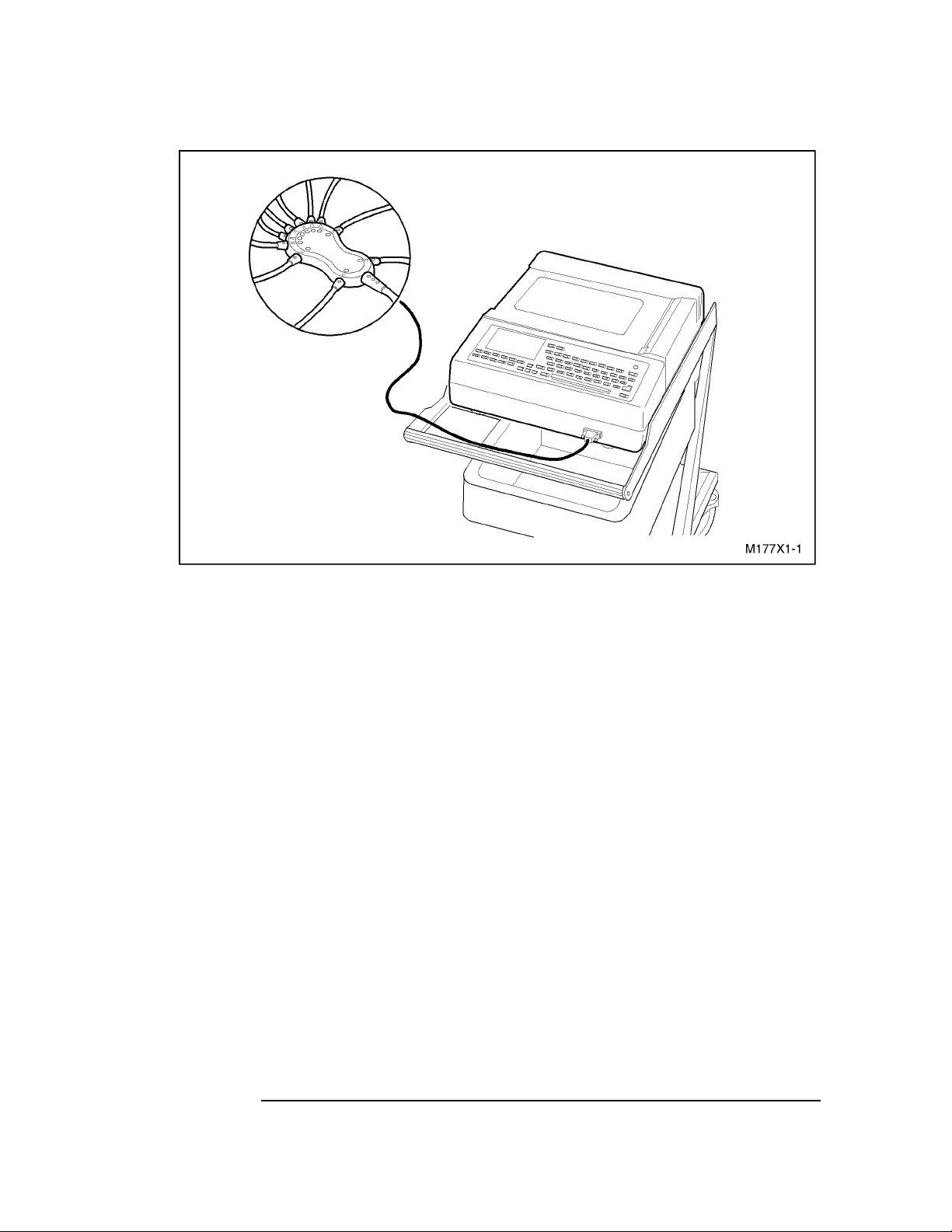
PageWriter 100, 200, 200i, and 300pi Series Cardiographs
Figure 1-1 M1770A/M1771A PageWriter 300pi/200i/200 Cardiograph.
The PageWriter 100, 200, and 300 family of cardiographs print ECGs in Auto and
Manual formats. All PageWriter cardiographs use a continuous feed, high-resolution,
thermal array printer. This produces electrocardiograms on standard- size paper that can
be included in patient records without cutting or mounting. ECG reports clearly show the
ECG waveforms. The PageWriter 200 and 300 series cardiographs also annotate records
with patient information and ECG measurements. The Pa geWriter 200i and 300pi also
includes ECG interpretation for both adult and pediatric patients.
From a service standpoint, the PageWriter 100, 200, and 300 family of cardiographs are
similar except for two major hardware differences:
• The M1770A has additional firmware for ECG measurements and interpretation.
• The M1771A has additional firmware for ECG measurements.
• The M1772A keypanel does not have an LCD preview dis play and uses operation al keys
instead of alphanumeric keys for user input.
All other model differences are found in the cardiograph’s software.
The PageWriter 100, 200, and 300 family of cardiographs is designed for low-cost, longterm reliability. The modular design makes extensive use of VLSI and gate array
technology, resulting in a minimum number of subassemblies. The modular approach
means less down-time for the user, since replacing subassemblies allows faster field
repairs. The internal self-test efficiently identifies faulty subassemblies , further speeding
the repair process.
1-2
Page 15
Inquiries
M1705B Cart
The optional M1705B Cart provides mobility for the PageWriter 100, 200, and 300 family
of cardiographs. The large wheels make the cart easy to move, yet steady. Slots in the
cardiograph’s feet and a thumbscrew secure the cardiograph to the cart rails. The tray
directly below the cardiograph provides stor age for the user’s gu ide. Storage for the power
cable is built in. Other built-in cable retainers hold the patient data cable ou t of the way.
Two compartmented trays provide storage for spare patient electrodes and patient cables,
additional thermal paper, and consumable supplies.
Transmission and Storage, Option #A05
Transmission and storage features are available for the M1770A and M1771A with
purchase of Option #A05. Up to thirty Auto ECGs can be stored in the cardiograph’s
internal flash memory. Stored ECGs can be recalled later for editing, re-analyzing,
printing, or transmission to another PageWriter 200/200i/300pi equip ped with Option
#A05, a PageWriter XLi cardiograph, a TraceMaster ECG Management System, or
facsimile machine. Manual ECGs cannot be transmitted or stored.
1Inquiries
Refer any questions or comments regarding these instruments to the nearest HewlettPackard Sales/Service Office or to one of Hewlett-Packard’s Service Dispatch Centers.
Always identify the instrument by model number and serial number in all correspond ence.
Telephone numbers for Service Dispatch Centers and Sales/Service Offices are listed in
Chapter 6, “Parts List.”
1Specification Data
The following tables list the technical specifications for the cardiographs and the mobile
cart. Specifications are the same for all models except as noted
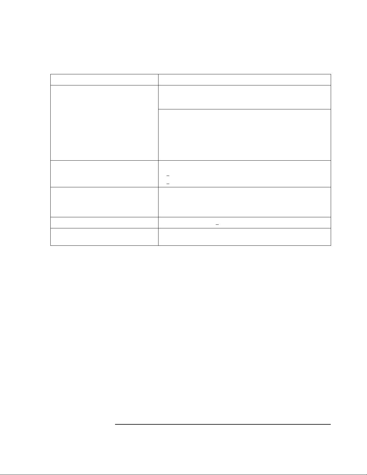
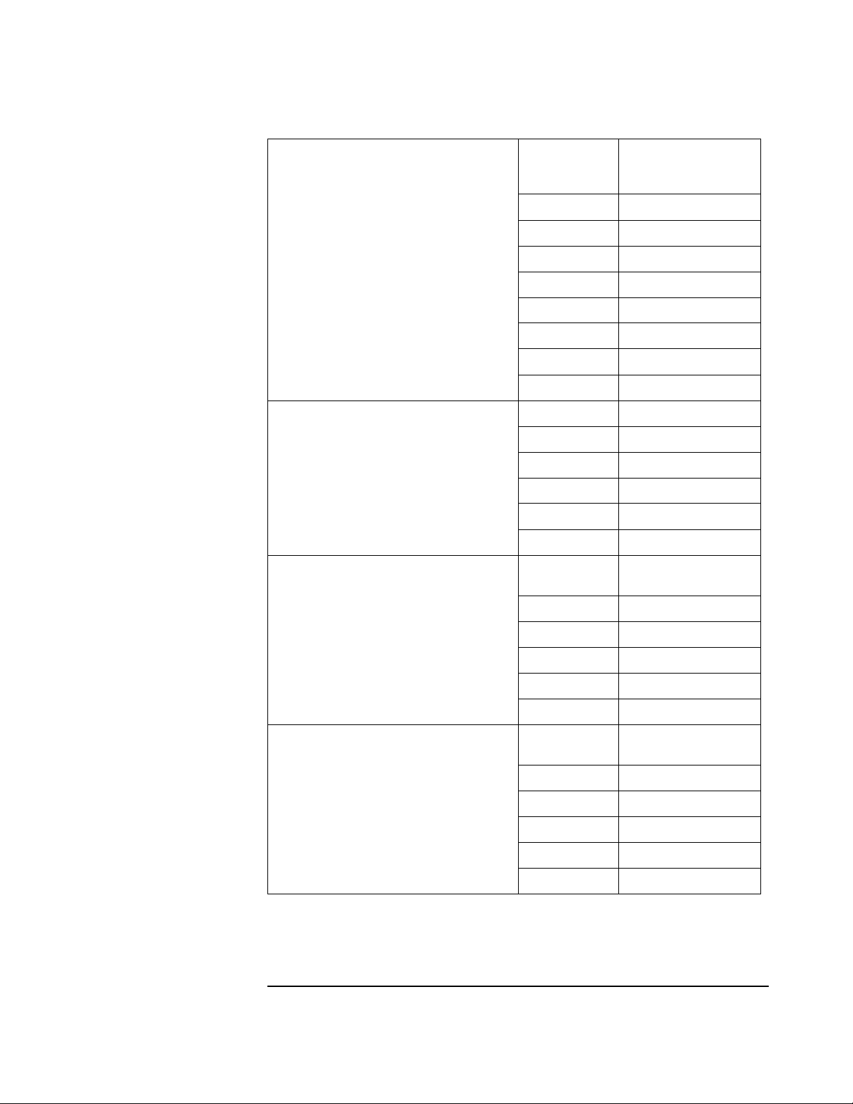
Table 1-1 Physical Specifications
Parameter Specification
Dimensions (h × w × l)
× 15 in × 17 in (11. 5 cm × 39.2 cm × 43.7 cm)
cardiograph
cart
Weight
cardiograph
cart
4 in
× 17 in × 33 in (91.4 cm × 43.5 cm × 84.8 cm)
36 in
18.7 lbs. (8.5 kg) or l es s (includes battery , 200 sheets of paper, pa ti ent cable, and power cord)
38 lbs. (17.24 kg)
Chemical resistance,
cleaners
Withstands the following: isopro py l alcohol (except patient cabl e ), mild soap and water, chlorine
bleach and wate r (30 ml/l of water).
1-3
Page 16
Specification Data
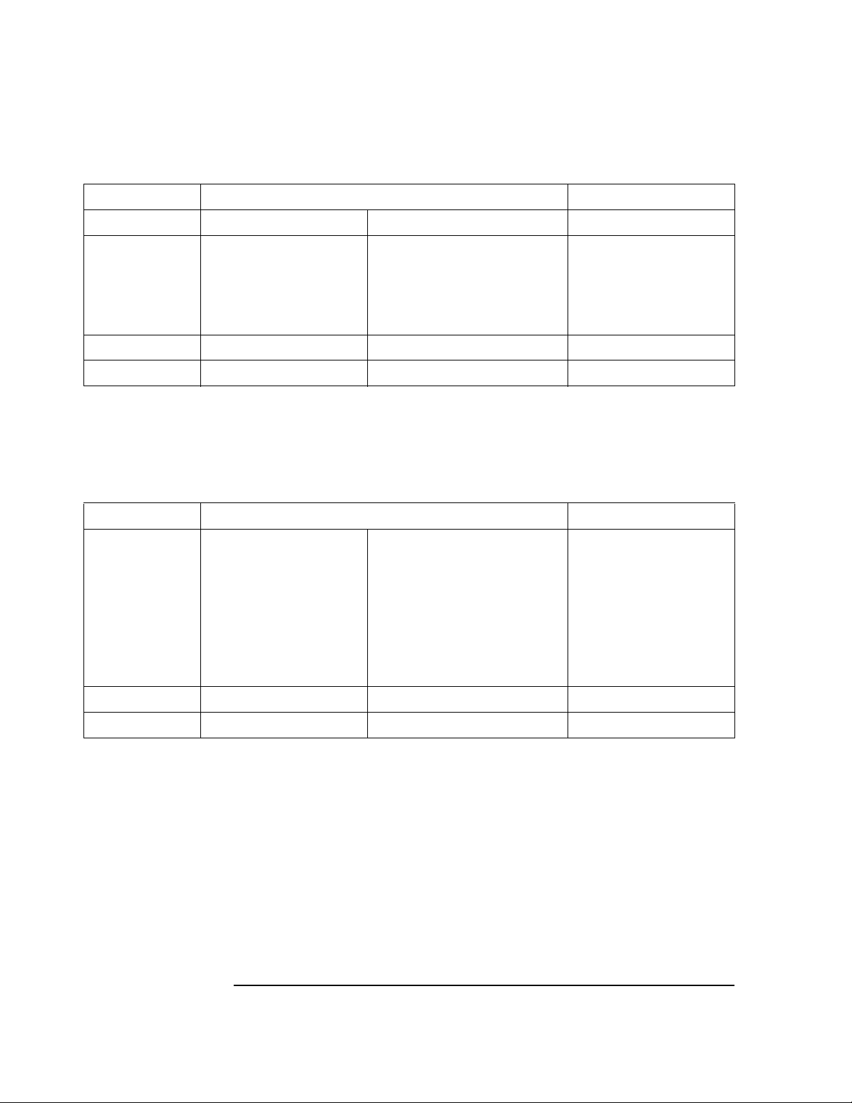
Table 1-2 Electrical Specifications
Parameter Specification
Resolution
ECG (internal)
display
5 µV
128 row pixels by 24 0 column pixels
display sweep sp eed
Input impedance greater than 2.5 MΩ@ 10 Hz, typically greater than 100MΩ @ DC
Gain accuracy
Input bias less than 40 nA for input leadwire, les s t han 500 nA for Right L eg output
Common mode rejection
Defibrillator reco ve ry
Crosstalk rejection
Sample rate 4.096M samples per second per input le adwire (unfiltere d)
DC offset tolerance
Noise
Standardizing voltage
50/60 Hz notch filter 50/60 Hz AC line rejectio n filters are always active.
Pacemaker pulse display > 0.2 mV indication for pa ce pulses between 0. 5 and 2 ms dur ation at amplit ude
1
Meets or exceeds AAMI EC11-1991 standard for Diagnostic Electrocardiographic Devi ces.
2
Meets or exceeds AAMI EC11-1991 standard for Diagnostic Electrocardiographic Devices. Tested according to AAMI
23.1 mm/sec
±5% of input signal or ±40 µV, whichever is greater
leadwire
110 dB or greater with A A MI test circuit
System recovery 8 seconds after 360 joule discharge, no damage
Less than 2% chan nel crosstalk
≥ ±300 mVdc with less tha n 5% gain change
≤ 30 µV peak-to-peak RTI
1 mV
2 to 250 mV
± 1%
1
1
1
± 5% for 100 mSec ± 5 mSec
1
1
2
1
1
1
1
EC11-1991 test method 4.2.7.1.
Sampling Characteristics of Cardiograph
Physiological factors such as breathing can cause variation in amplitudes of heart beats,
independent of the heart rate. In addition, sampled systems (as opposed to continuous
systems) may show changes in the apparent height of the R-wave when sampling of the Rwave occurs slightly off-peak. Because the sampling rate and the heart rate are
asynchronous, the time between the peak and an adjacent sample can vary from one QRS
complex to the next. This results in a slight variation o f dis playe d QRS amplitude. This
effect is more pronounced wi th narrower si gnals, more commonly found in some pediat ric
electrocardiograms and in pacemaker pulses. The M177XA family of cardiographs
minimizes this effect by:
• using an integrating-type A/D converter
• sampling all leadwires simultaneously
• oversampling the signals
• processing the oversampled si gnals with appropriate digital si gnal process ing techniques
1-4
Page 17
Specification Data
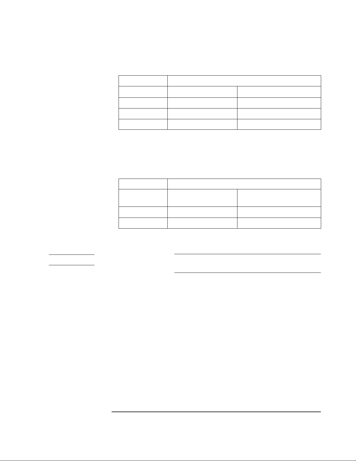
Table 1-3 ECG to Paper Specifications
Parameter Specification
Frequency response of PageWriter
High Pass Low Pass
200/200i/300pi
(-3dB bandwidth)
Auto ECG
Manual ECG
0.05 Hz
0.15 Hz
0.5 Hz
0.05 Hz
0.15 Hz
0.5 Hz
1
1
3
150 Hz
100 Hz
40 Hz
150 Hz
100 Hz
40 Hz
1
2
3
2
Frequency response of PageWriter 100
Auto ECG
Manual ECG
1
3
<3 dB down at (u ser selectable):
3 dB down at (user selectable):
<
0.15-150 Hz or 0.15-40 Hz
0.05-150 Hz or 0.05-40 Hz
ECG resolution on paper
voltage axis
time axis
Approximately 8 dots/mm (200 dots/in)
Approximately 20 dots/mm (500 dots/in) at 25mm/sec and slower
Approximately 10 dots/mm (250 dots/in) at 50mm/sec
Recorder speed 5, 10, 25, and 50 mm/sec +
1.5%
4
ECG visibility with pace pulse Meets or exceed AMMI EC11-1991 standard for Diagnostic Electrocardio-
graphic Devices
1
Bold entries mean meets or exceeds AAMI E C 11-1991 standard for Diagnostic Electrocardiographic Devices. Meets
frequency response standard 3.2.7.2 using methods A, D, and E with auto report filter settings at 0.05-150 Hz or
0.15-150 Hz.
2
-4 dB @ 100 Hz
3
Bold entries mean meets or exceeds AAMI E C 11-1991 standard for Diagnostic Electrocardiographic Devices. Meets
frequency response standard 3.2.7.2 using methods A, D, and E with manual report filter settings at 0.05-150 Hz.
4
Bold entries mean meets or exceeds AAMI E C 11-1991 standard for Diagnostic Electrocardiographic Devices.
1-5
Page 18
Specification Data
Table 1-4 Power Supply and Battery Specifications
Parameter Specification
AC line frequenc y
115 V setting
230 V setting
AC input power rating
Battery voltage 6 V DC, 6.5 Ah
Battery recharge time with unit off
(battery full y discharged)
to 90% capacity
to full capacity
Battery capacity
Auto
continuous rhythm (Manual mode)
Battery life
AC and battery operation
battery only operation
Low battery warning At least 2 Auto ECGs or at least 2 minutes of Man-
Table 1-5 Safety Specifications
Parameter Specification
ECG leads source curr ent to ground Less than 10 µA RMS
50 and 60 Hz (nominal)
90–132 Vac
198–264 Vac
50 VA
7 hours typical
16 hours typical
40 ECGs
40 minutes
Typically 24 month s
Typically 14–16 months
ual ECG is allowed after the Low Battery indication is given.
1
ECG leads sink current
120 Vac, 60 Hz
240 Vac, 50 Hz
1
2
Ground wire integrity
Shunting of defibrillator ene rg y
Operator safety during defibrillation
1
Meets or exceeds AAMI EC11-1991 st andard for Diagnostic Electrocardiographic
Less than 20 µA RMS with patient cable
Less than 50 µA RMS with patient cable
Less than 100 mΩ @ 25 A AC
1
< 10%
< 100 µC
1
1
Devices.
2
Meets or exceeds IEC 601-2-25 International Standard for Medical Electrical Equipment,
Part 2 for Electrocardiographs.
1-6
Page 19
Specification Data
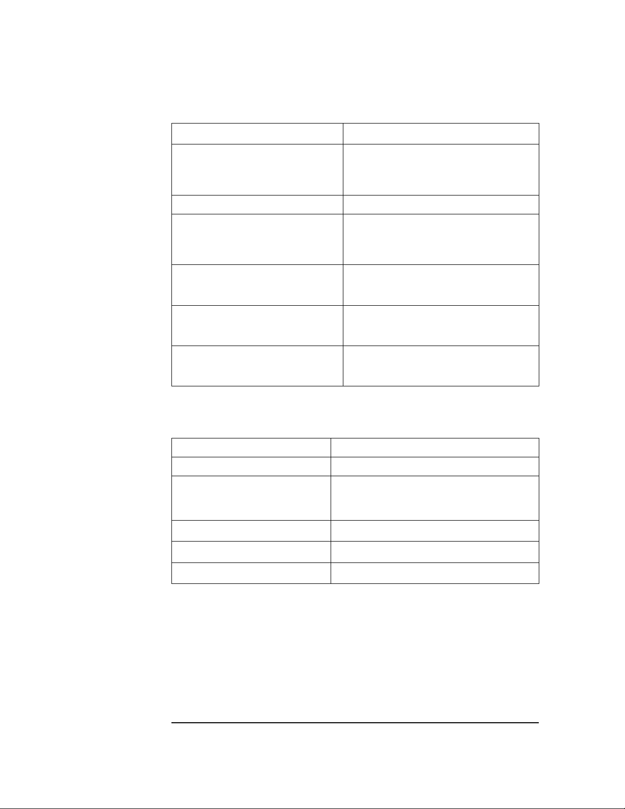
Table 1-6 Environmental Specifications
Parameter Specification
Temperature
operating
storage
Humidity
operating
storage
Pressure (altitude)
operating
storage
Table 1-7 Miscellaneous Specifications
Parameter Specification
Real time clock accuracy
10 to 40
° C
50
° to 104° F (10° to 40° C)
° to 122° F (0° to 50° C)
32
15 to 80% RH, non-condensing
15 to 90% RH, non-condensing
15,000 ft. (4600 m) for 2 hours
15,000 ft. (4600 m)
Less than 3 minutes deviation per month.
Printhead life Typically 100,000 pa ges
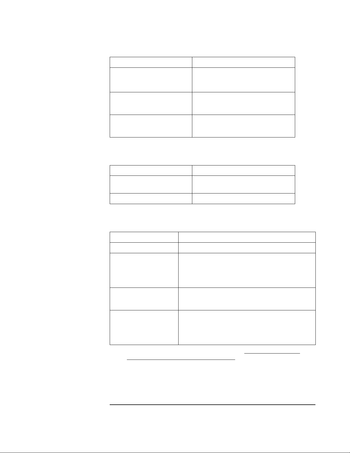
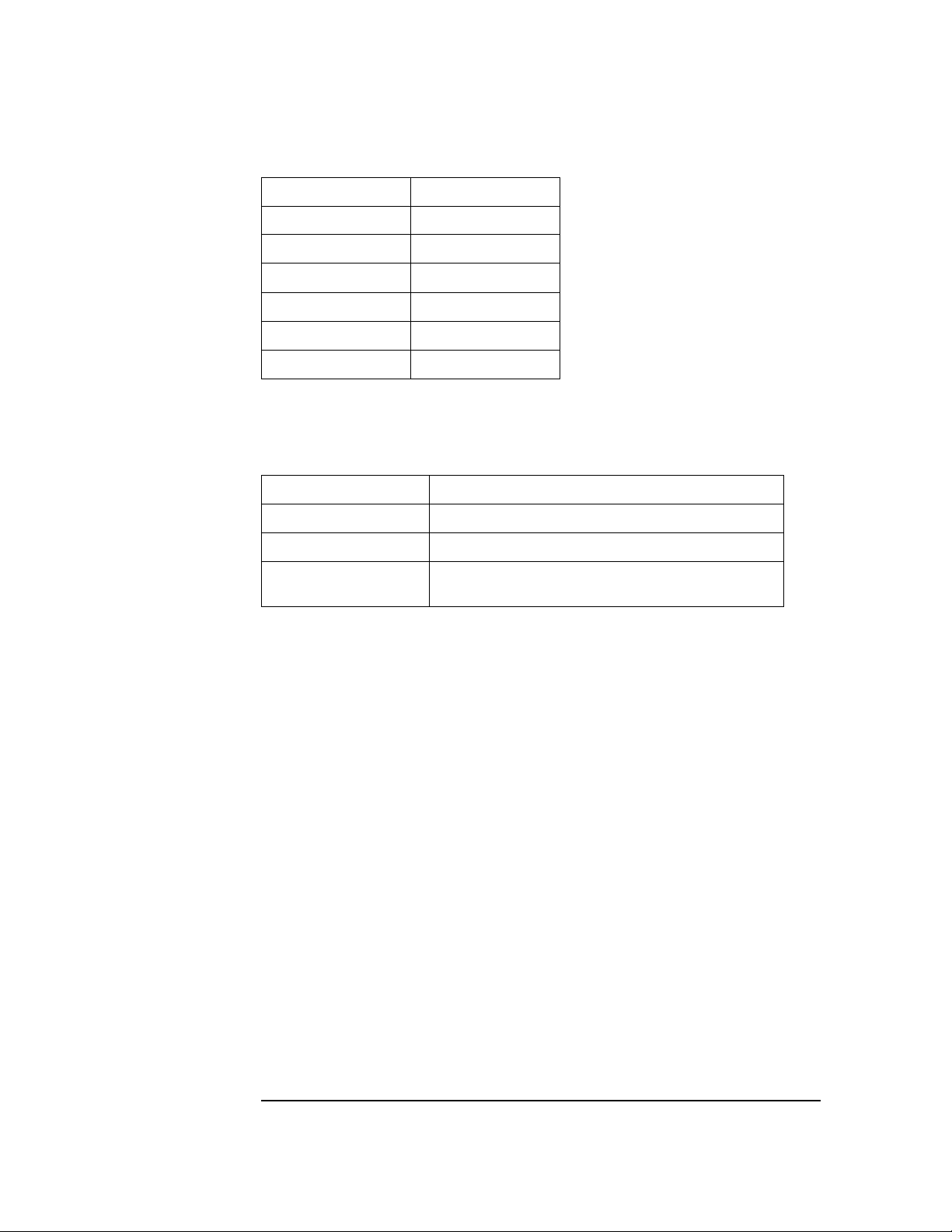
Table 1-8 Storage and Transmission Specifications (Option #A05 only)
Parameter Specification
Auto ECG storage capacity 30 ECGs
Transmission Protocols
DT
SCP
Modem command interfaces
Data modem
FAX modem
Modem protocols
Modulation
Error correction
Compression
FAX modulation
1
Described in the European Committee for Standardization, Standard Communications
Protocol - Computer - Assisted Electrocardiography. (CEN/TC 251).
Data transmission standard used betwee n HP PageWriter cardiographs and HP TraceMaster ECG Management System s
Standard Communications Protocol
Hayes standard AT command set
EIA/TIA-578 Serv i ce Cl ass 1
V.34
V.42
V.42 bis
V.17
1
1-7
Page 20

Options and Accessories
1Options and Accessories
PageWriter 100, 200, 200i, and 300pi Cardiographs
These tables list the options and accessories available for the PageWriter 100, 200, and
300 family of cardiographs.
Country/Re gion Options
Each country/region option includes the appropriate power cord, voltage, printer, patient
cable, and language. See Table 1-9, which shows th e configuration o f each coun try/region
option.
1-8
Page 21

Options and Accessories
NOTE
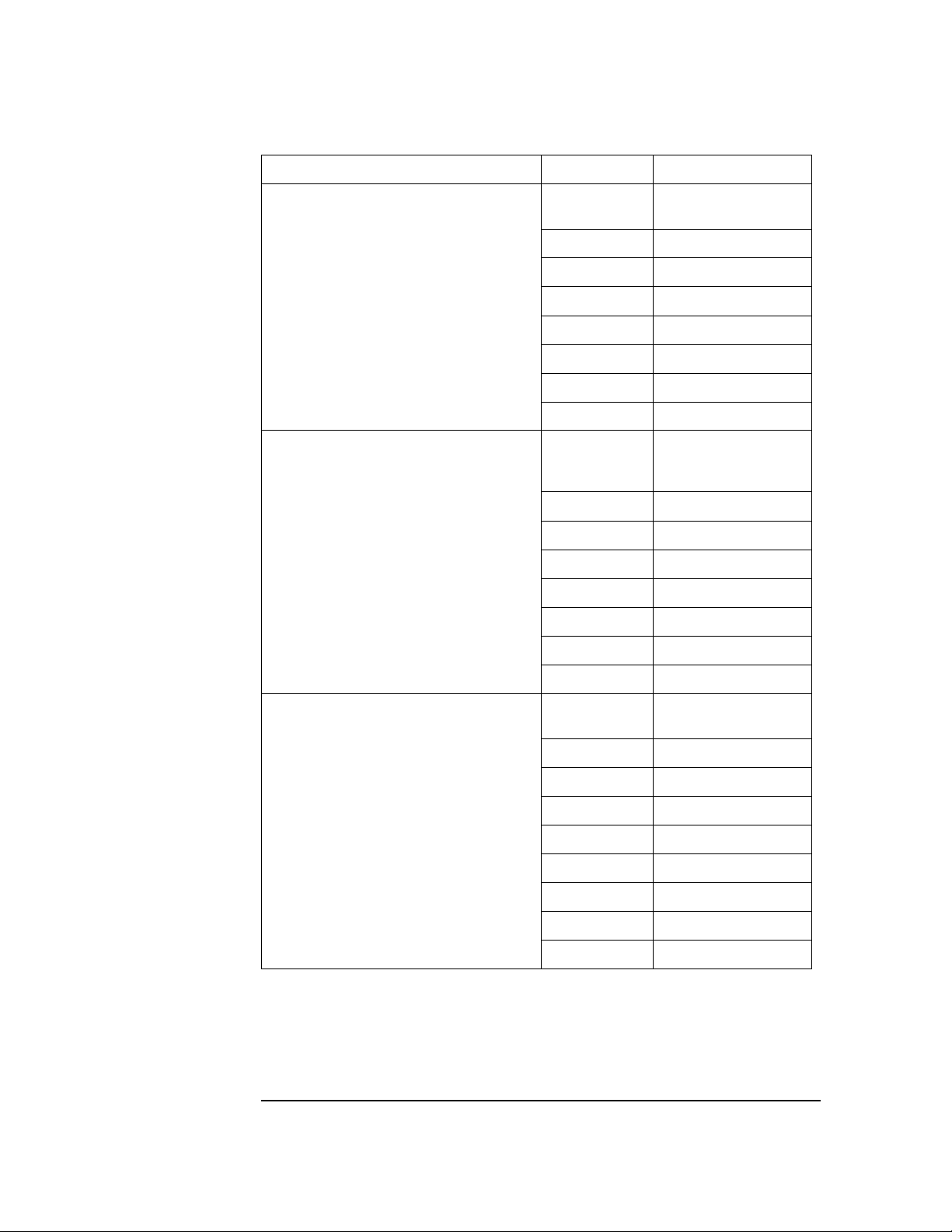
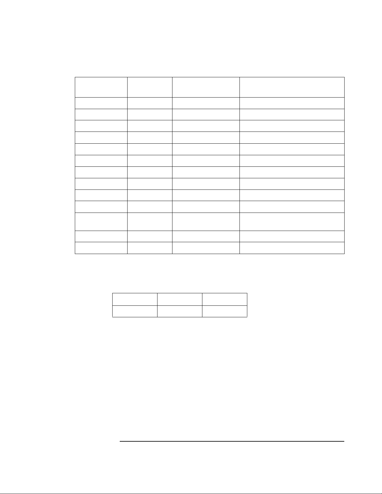
Table 1-9 Country/Region Option Configurations
Country/
Option
ABA North America English English A AHA 120 903–US Disposable
ABB Europe En gl ish English English A4 IEC 220 902–Europe None
ABC French Ca nada French French A AHA 1 20 903–US Disposable
ABD Germany German German A4 IEC 220 902–Europe None
ABE Spain Spanish Spanish A4 IEC 220 902–Euro pe None
ABF France French French A4 IEC 220 902–Europe None
ABG Australia English English A4 AHA 240 901–Australia Welsh
ABH Netherlands Dutch Dutch A4 IEC 220 9 02–Europe None
ABK Intercon
ABM Latin America Spanish Spanish A AHA 120 903–US Welsh
ABN Norwegian Norwe-
ABS Sweden Swedish Swedish A4 IEC 220 902-Europe None
ABU United Kingdom English English A4 IEC 240 900 –U K None
Region Labels
English English A AHA 120 903–US Welsh
English, Taiwan
gian
User
Manuals Printer
Norwe-
gian
A4 IEC 230 902-Europe None
AHA/
1
IEC Volts Power Cord
2
Electrodes
ABX Finland Finnish Finnish A4 IEC 220 902-Eu rope None
ABZ Italy Italian Italian A4 IEC 220 902–Europe None
AB2 China Chinese Chinese A4 IEC 220 922–Chi na Welsh
AB4 Singapore English Englis h A4 AHA 240 900–UK Welsh
AC6 S. Korea English English A AHA 220 902-Europe Welsh
ACJ India English English A4 IEC 240 917-SA Welsh
AKM China Chinese English A4 IEC 220 922-China Welsh
ACQ South Africa English English A4 IEC 220 9 17–SA None
AKV South America Spanis h Spanish A A H A 220 902–Europe Welsh
1
In Table 1-9 an “A” in the Printer column refers to 8.5 x 11-in. paper; “A4” refers to 210 x 29 7-mm paper
2
See Table 1-11 for HP part numbers
Switzerland should order the desired language (German, French, Italian, or English) and
the Swiss power cord (HP 8120-2296).
1-9
Page 22
Options and Accessories
Table 1-10 PageWriter 300pi, 200/200i and 100 Series Documentation Part Numbers
Document Title Language Part Number
PageWriter 100 Cardiograph User’s Gui de
(M1772A)
PageWriter 200/20 0i Car diograph Users’s
Guide (M1770A, M1771A with Serial # Prefix
CNA, CNB, CNC, 3807A or earlier version)
English M1772-91900
French M1772-91901
German M1772-91902
Dutch M1772-91903
Spanish M17 72-91904
Italian M1772-91905
Finnish M1772-91910
Chinese M1772-91908
English M1772-91900
French M1770-91901
German M1770-91902
Dutch M1770-91903
Spanish M1770-91904
Italian M1770-91905
PageWriter 300p i Ca rdiograph Users’ s G uide
(M1770A with Serial # Prefix CND)
Swedish M1770-91906
Finnish M1770-91910
English M1770-91930
French M1770-91931
German M1770-91932
Dutch M1770-91933
Spanish M1770-91934
Italian M1770-91935
Swedish M1770-91936
Norwegian M1770-91938
Finnish M1770-91939
1-10
Page 23
Options and Accessories
Table 1-10 PageWriter 300pi, 200/200i and 100 Series Documentation Part Numbers
PageWriter 300p i Pred ictive I nstr uments Quic k
Reference Guide (M1770A with Seria l # Pre fix
CND)
Interpretive Ph ysician’s Guide (M1770A) English M1700-92 908
English M1770-92800
French M1770-92801
German M1770-92802
Dutch M1770-92803
Spanish M1770-92804
Italian M1770-92805
Swedish M1770-92806
Norwegian M1770-92808
Finnish M1770-92809
French M1700-92918
German M1700-92928
Dutch M1700-92938
Spanish M17 00- 92948
Italian M1700-92958
Interpretive Physician’s Guide - Addendum
(M1770A)
Predictiv e Instruments Physic ian’s Guid e
(M1770A with Serial # Prefix CND)
English M1700-90700
French M1700-90701
German M1700-90702
Dutch M1700-90703
Spanish M1700-90704
Italian M1700-90705
English M1792-93900
French M1792-93901
German M1792-93902
Dutch M1792-93903
Spanish M1792-93904
Italian M1792-93905
1-11
Page 24
Options and Accessories
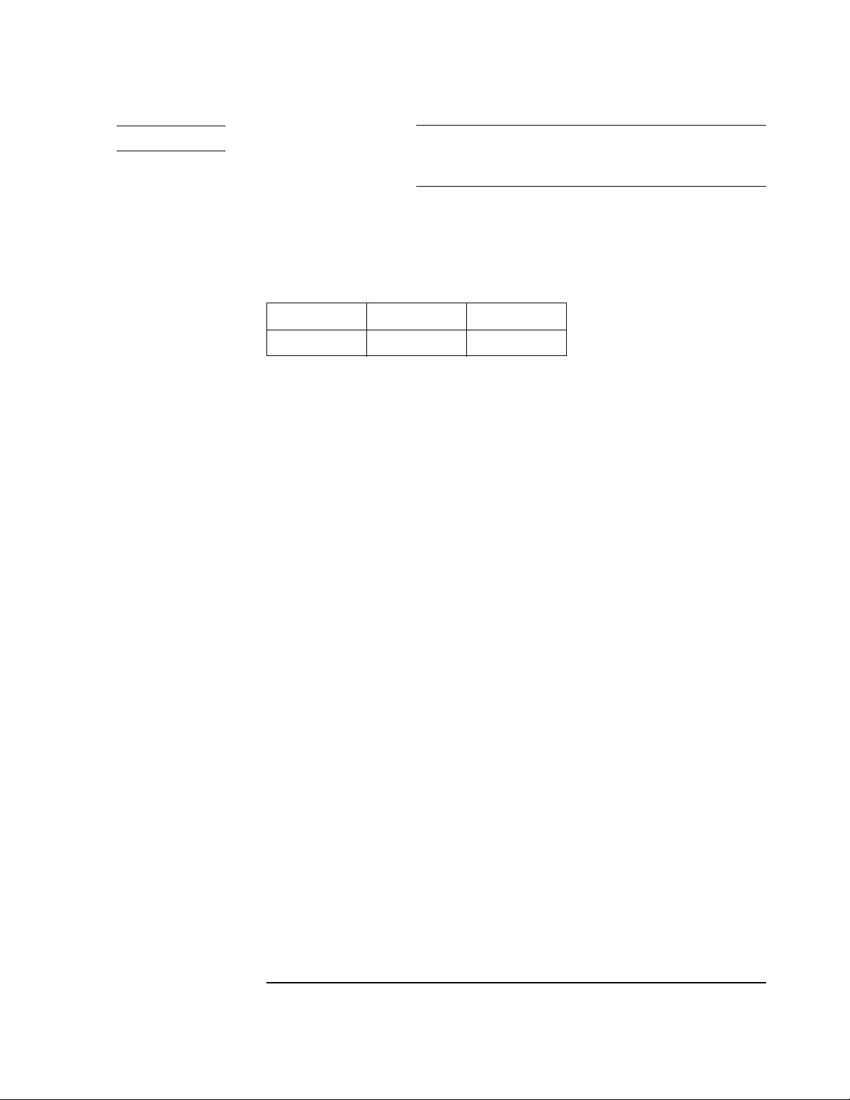
Table 1-11 Power Cord Part Numbers
Power Cord Key HP Part Number
900 8120-1703
901 8120-4464
902 8120-1692
903 8120-5213
917 8120-4600
922 8120-8377
Table 1-12 Options
Option Description
A05 Adds storage and transmission capability
M2488A-#A70, A71, A72 StressWriter system includes Pa geWriter cardiograph
M2488A-#C70 StressWriter system includes interface card for PageWriter
cardiograph
Standard Accessories
Accessories included are based on model number and localization.
• 200 sheets of z-fold paper
-English paper p/n M2481A
-Metric paper p/n M2483A
• PageWriter 300pi HP M1770A Cardiograph User’s Guide (PageWriter 300pi)
• PageWriter 200/200i HP M1771A/M1770A Cardiograph User’s Guide (PageWriter
200/200i)
• Hewlett Packard Interpretive Cardio graph Physician’s Guide (PageWriter 200i/300pi
only)
• PageWriter 100 HP M1772A Cardiograph User’s Guide (PageWriter 100 only)
• Using the HP PageWriter 200/200i Cardiograph Operator Training Video (PageWriter
200/200i, also for use with PageWriter 300pi)
• Using the HP PageWriter 100 Cardiograph Operator Training Video (PageWriter 100
only)
1-12
Page 25

Performance Verification and Maintenance
NOTE
1Introduction
This chapter describes how to verify the cardiograph’s performance, explains preventive
maintenance, presents patient safety informatio n, and provides a performance verification
checklist.
1Performance Verification
Several procedures make up performance verification: visual inspection of the
cardiograph exterior, execution of Extended Self-test, visual examination of an ECG
recorded from an ECG patient simulator, and system safety tests using a safety analyzer.
A Performance Verification matrix which appears at the end of this section specifies the
tests and inspections which must be performed follo wing servicing of the PageWriter
cardiographs. The Performance Verification test results must be recorded on
Customer Service order records
Make copies of the matrix. Fill out a copy each time the cardiograph is tested. Attach the
printer test output, and simulator ECG trace to the completed matrix and file with the
cardiograph’s permanent maintenance record.
If any of the performance verification tests fail, refer to Chapter 4, Troubleshooting.
2-1
Page 26

Performance Verification
Visual Inspection and Power On Self Test
Before beginning the inspectio n, press the key to put the cardiograph in
2Q6WDQGE\
Standby mode, and unplug the power cord from the wall outlet. Inspect the cardiograph
for the following:
• Worn or damaged power cord
• Loose or missing hardware
• Mechanical damage
• Evidence of liquid spill
• Worn printer drive gear
• Worn printer roller
• Corroded or damaged reusable electrodes, if present
• Damaged patient cable
• Dirt/paper residue on the thermal printhead
• Frayed or damaged wiring
Replace any damaged or missing items, and clean the printhead and patient electrodes as
necessary. Cleaning instructions are listed under “Preventive Maintenance” later in this
chapter. Connect the cardiograph to AC power. Be sure that the AC indicator comes on.
Turn the cardiograph On and observe that the display turns on (PageWriter
200/200i/300pi) or that the LED’s flash on (PageWriter 100).
Extended Self-test
The cardiograph’s extended self-test checks each major subassembly. The extended selftest consists of two sections: the testing of internal circu itry and the testing of printer,
display, keyboard, and modem capabilities.
To begin the extended self-test, press and hold both the and keys while
turning on the cardiograph with the key.
2Q6WDQGE\
To stop or exit extended self-test, you must press to place the cardiograph
$XWR 0DQXDO
2Q6WDQGE\
in Standby.
Internal Circuitry Testing of PageWriter 100
These tests are performed on the internal circuitry:
•Memory
• Gate Array
• Front-End Interface
• Serial Interface
Each of these tests is described in detail later in this chapter.
When the internal circuitry test of the PageWriter 100 is performed, the LEDs show which
test is being performed. The following table shows which LED is associated with each
test.
2-2
Page 27
Performance Verification
Table 2-1 PageWriter 100 Test LED’s
Test Number Test Name LED(s) lit on Page-
Writer 100
1 ROM-1 5 mm/mV OK
2 ROM-2 10 mm/mV Normally fails for 100.
3 ROM-X1 20 mm/mV OK for A#10.
4 ROM-X2 V Leads OK for A#10.
5 RAM Filter OK
6 NVRAM Auto OK
7 GA I II III Lead Group Will also flash all LEDs. OK
8 ECG FE aVR aVL aVF Lead Group OK
9 SIO II aVF V2 Lead Group OK for A#10.
A REMOTE V Leads For future use - normally fail s.
B MODEM 5 mm/sec OK for A#10, with modem or test tool
C FLASH1 10 mm/sec OK for A#10.
D FLASH2 25 mm/sec OK for A#10.
When the tests are completed, the results are also printed out in a pass/fail format
on the left-hand side of the first page of the test repor t.
Comments/Expected Results
attached
Table 2-2 Test Results Format
Test Passes Test Fails
Printed Result OK **
In some cases, a test failure halts the test/test printout and an error code indicating the
failure is flashed on the LED’s. See Chapter 4, “Troubleshooting,” for a list of self-test
failure codes and failure symptoms. The section “How the PageWriter 100 Communicates
Error Codes and Messages” in Chapter 4 describes how to read the LED’s.
2-3
Page 28

Performance Verification
Internal Circuitry Testing of PageWriter 200/200i/300pi
These tests are performed on the internal circuitry:
•Memory
• Gate Array
• Front-End Interface
• Serial Interface
Each test is described detail later in this chapter.
When testing the internal circuitry of the PageWriter 200/200i/300pi, the numbers 1
through 9 and the characters A through D are displayed one at a time beginning with
number 1. Each number represents a particular test. If the test fails, the character X is
placed after the test number, for example, 3X. The test descriptions below are listed in the
order the tests are performed.
Table 2-3 PageWriter 200/200i/300pi Test Numbers
Test Number Test Name Character Displayed on Page-
Writer 200/200i/300pi
1ROM-1 1 OK
2 RO M-2 2 Passes for 300pi, 200i, and 200 with
3 ROM-X1 3 Passes for Options #A05 an d #A10
4 ROM-X2 4 Passes for Options #A05 an d #A10
5RAM 5 OK
6 NVRAM 6 OK
7GA 7 OK
8ECG FE 8 OK
9 SIO 9 Passes for Options #A05 and #A10
A REMOTE A For future use - norm ally fails
B MODEM B Passes for Options #A05 and #A10
Comments
software revision A.05.0 6 or later.
only.
only.
only.
only, with modem or test tool
attached
C FLASH1 C Passes for Options #A05 and #A10
only
D FLASH2 D For future use - normal ly fails
2-4
Page 29
Performance Verification
CAUTION
If your cardiograph is equipp ed with Option s #A05 or #A10, do not tu rn it off duri ng Test
C or D. If you turn off the cardiograph while Test C or D are in process, you could lose
stored ECGs, the Log of ECGs Stored, or the Log of ECGs Taken.
When the tests are completed, the results are printed out in a pass/fail format on the lefthand side of the first page of the test report.
Table 2-4 Test Results Format
Test Passes Test Fails
Printed Result OK **
In some cases, a test failure halts the test/test printout and an error code indicating the
failure appears on the display. See Chapter 4, “Troubleshooting,” for a list of self-test
failure codes and failure symptoms.
Memory Test
This test looks for failures in the following memory subsystems:
• Read-Only Memory (ROM)
• Random Access Memory (RAM)
• Non-Volatile Random Access Memory (NVRAM)
Read-Only M emory (tests 1-4) . The cardiograph is designed to have up to four ROMs
installed, two on the main control board and two on an option board. The Read-Only
Memory test reads the contents and performs a 32-bit cyclic redundancy check (CRC) of
each of the four ROM address spaces. The test of a ROM address space will fail if the
ROM module is faulty or is not present. The four ROM address spaces are identified on
the report as
•ROM-1
•ROM-2
•ROM-X1
•ROM-X2
Depending on the serial number and model of the unit you are servicing, the
corresponding ROM part numbers vary. Refer to tables 2-5, 2-6, 2-7, and 2-8 for the
correct ROM replacement part numbers.
2-5
Page 30
Performance Verification
Table 2-5 ROM Replacement Part Numbers for PageWriter Cardiographs M1770, M1771A Serial Number
Prefix CNA, CNB, or CNC,3807A or earlier
Test ROM Part Number Language
ROM 1
ROM 2 U206 - Main CPU Board M1770-89521
ROM X1 U9 - Interface Board M2488-17901
ROM X2 U10 - Inte rf ace Board M 2488-17902
U205 - Main CPU Board M1770-89505
M1770-89521
M1770-89522
M1770-89523
M1770-89524
M1770-89525
English
French
German
Dutch
Spanish
Italian
Table 2-6 ROM Replacement Part Numbers for PageWriter Cardiographs M1770, M1771A Serial Number
Prefix CND
Test ROM Part Number Language
ROM 1
ROM 2
U205 - Main CPU Board M1770-89550
M1770-89551
M1770-89552
M1770-89553
M1770-89554
M1770-89555
M1770-89556
M1770-89558
M1770-89559
English
French
German
Dutch
Spanish
Italian
Swedish
Norwegian
Finnish
ROM X1 U9 - Interface Board M2488-17901
ROM X2 U10 - Inte rf ace Board M 2488-17902
2-6
Page 31
Performance Verification
NOTE
Table 2-7 ROM Replacement Part Numbers for PageWriter Cardiographs M1772A Serial Number
Prefix CNA, CNB, or CNC,3807A or earlier
Test ROM Part Number
ROM 1
ROM 2 Not Required
ROM X1 U9 - Interfac e Boa rd M 2488-17901
ROM X2 U10 - Inte rf ace Board M 2488-17902
U205 - Main CPU Board M1770-89 505
Table 2-8 ROM Replacement Part Numbers for PageWriter Cardiographs M1772A Serial Number
Prefix CND
Test ROM Part Number
ROM 1
ROM 2
ROM X1 U9 - Interfac e Boa rd M 2488-17901
ROM X2 U10 - Inte rf ace Board M 2488-17902
U205 - Main CPU Board M1770-89 550
If ROM-1 is defective, it is unlikely this test or any other cardiograph function will
operate.
Random-Access Memory (test 5) . The RAM test performs a read/write test of the
instrument’s memory. If this subsys tem is defective, it is unlikely this test or any other
cardiograph functions will operate. The RAM is identified on the report as
•RAM
2-7
Page 32

Performance Verification
Non-Volatile Random Access Memory (test 6) . Each 2-byte location of NVRAM is
written and read with a pseudo-random pattern. This is a non-destructive test. The
contents of the NVRAM are saved in RAM prior to this test, and then restored when the
test is complete. The NVRAM test result is identified on the report as
• NVRAM
System Gate Array Test (test 7) . Various registers in the System Gate Array are read
and written. The System Gate Array test result is identified on the report as
• GA
Front-End Interface Test (test 8) . The front-end interface test verifies that the ECG
front-end circuitry is responding to commands, and that the input multiplexers are
operating between ground and internal reference voltage. The front-end interface test
result is identified on the report as
•ECG FE
Manufacturing/Serial Interface Test (test 9) . The manufacturing/serial interface test
checks for proper communication with the optional expansion card UART. For this test to
pass, an extender card must be plugged into the expansion connector. The serial interface
test result is identified on the report as
•SIO
Remote Test (test A). The remote test checks the ability to transmit and receive data
through the spare remote port on the optional expansion board. The remote test is
identified on the report as
• REMOTE
Modem Test (test B) . The modem test verifies that the cardiograph is sending the
expected signals to the modem, and that the modem is receiving and responding
appropriately to signals from the cardiograph. The optional expansion board must be
installed to connect to the modem. The front end and RS-232 port test tool described in
Chapter 4 can help differentiate modem and cardiograph problems. See the section in
Chapter 4 titled “Test Tools” for instructions about using th is tool. The modem test is
identified on the report as
• MODEM
2-8
Page 33

Performance Verification
CAUTION
Flash Memory Tests (tests C an d D) . The flash memory tests verify that the flash
memory on the optional expansion board can be erase, and that information can be stored
and retrieved. The flash memory tests are identified on the report as
•FLASH1
•FLASH2
If your cardiograph is equi pped with Option #A05 or #A10 , do not turn it off during Test
C or D. If you turn off the cardiograph while Test C or D are in process, you could lose
stored ECGs, the Log of ECGs Stored, or the Log of ECGs Taken.
2-9
Page 34
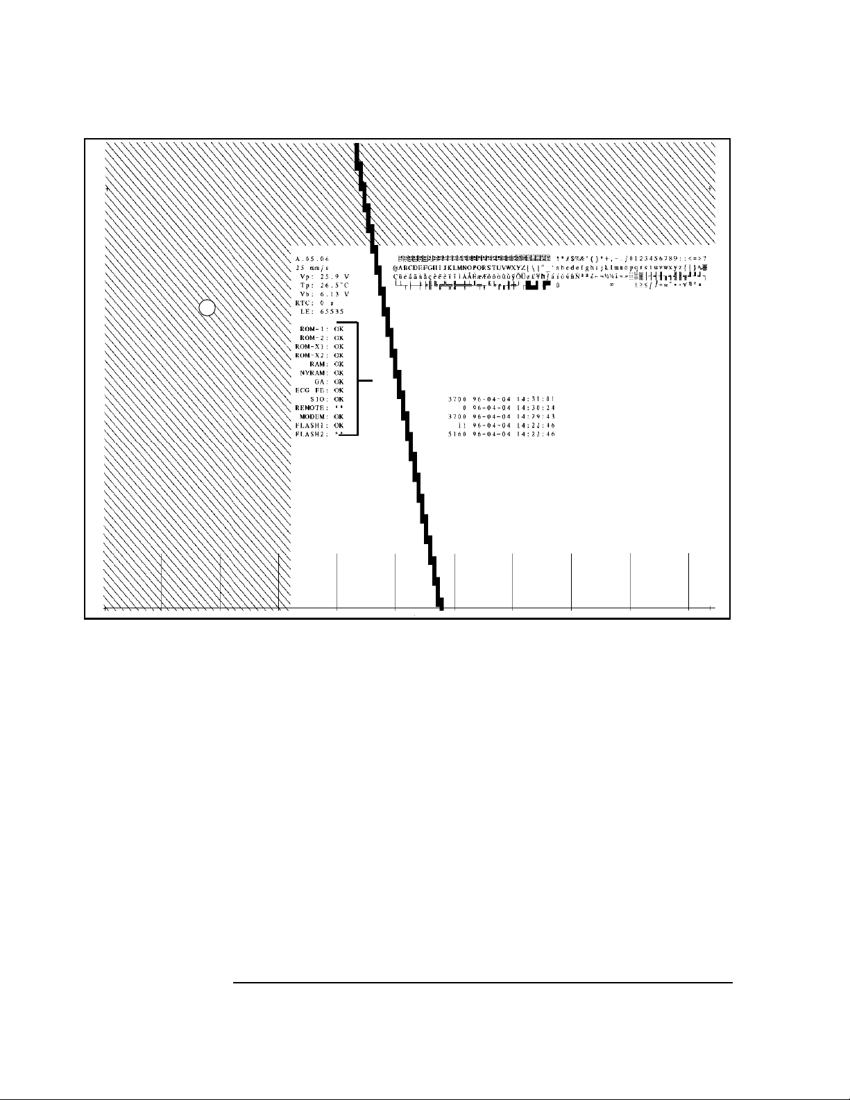
Performance Verification
Figure 2-1 An Extended Self-Test Report Example
F
G
I
D
K
L
A. Test Results
B. Character Set
C. Timing Tics
D. Diagonal Lines
E. Stepped Bars
F. Software Revision
G. Printer Speed
H. Printhead Voltage
I. Printhead Temperature
J. Battery Voltage
K. Time Stamp
L. Last Error
M. Event Log (Option #A05 only)
B
H
J
A
M
E
C
2-10
Page 35

Performance Verification
How to Read the Extended Self-Test Report
Each printed page of the extended self-test contains the following information:
A Test Results - See the previous section.
B Character Set - Characters 0 through 255 are printed as a table 4x64 characters in
size. This checks the character tables and printhead performance.
C Timing Tics - Vertical lines are drawn from the bottom of the page. Each vertical
line is 25 mm long as measured from the horizontal line drawn across the bottom of
the page. Spacing between timing ticks is 25 mm ± 1.5%.
D Diagonal Lines - These dense diagonal lines are printed across the top 2 inches of
the report and quickly show speed variations. An 8 cm wide column of diagonal
lines is also printed down the left-hand side of the repo rt, s tartin g at the top-o f-fo rm
hole, to show whether the print roller is round.
E Stepped Bars - The stepped bars are 1/4-inch thick and 3/4-inch tall, stepping from
the top of the page to the bottom of the page. These bars are used to show printhead
dots that are burned out.
F Software Revision - The software revision number for the base ROM.
G Printer Speed - mm/sec
H Printhead Voltage - Voltage range is 25.6 to 26.6 V
I Printhead Temperature - degrees Celsius.
J Battery Voltage - Voltage range is 5.2 - 7.5 V.
K Time Stamp - Number of seconds that the printer test has run.
L Last Error - The last error code encountered. An error code of 65535 indicates that
no errors have occurred since the instrument left the factory. See Table 4-1 for the
table of error codes.
M Event Log - List of the last 46 events with time and date stamp. The events are listed
with the most recent first. Event sub-codes have the same time stamp as the event
code, and appear on the line above the event code. See Table 4-2 for a table of event
codes.
2-11
Page 36

Performance Verification
NOTE
Display Test (PageWriter 200/200i/300pi only)
The display test shows test patterns on the display. Each of the following patterns appear
in this order:
• all pixels lit to create a black screen
• no pixels lit to create a white screen
• a vertical bar scrolling from left to right
You must observe the display while the test pattern is running to ensure:
• no burned out pixels
• no random lines or dots in the display
• no permanent patterns visible at normal contrast. Patterns may be visible at low contrast
(darker screen); this is normal.
• no LCD flickering
It is normal for the top row of the LCD to have some pixels on during the first sweep of
the vertical bar.
This test relies on the visual inspection of the test patterns for detecting failures. There is
no failure message for the display test.
Indicator Light Test (PageWriter 100 only)
During this test, all indicator lights turn on and off at least once. At one point, the indicator
lights flash rapidly for a short time.
Printer Test
The printer test exercises the printhead and paper drive mechanism by printing test
patterns and diagnostic data on the page. The patterns consist of a rectangular area that
contains the entire character font set, timing tics, diagonal lines, and stepped bars. On the
PageWriter 200/200i/300pi cardiographs, the printer test and the display test are
conducted simultaneously. The printer test continues until the cardiograph is placed in
Standby mode.
When the printout is complete, inspect it for:
• straight diagonal lines
• even spacing between diagonal lines
• consistent print quality for all p a tterns
• constant width between timing tics (25 mm ±1%)
• consistent length of timing tics
• accurate rendition of all characters
• clean stepped bars with no dropout in black areas
• even spacing between diagonal lines at the beginning of the page
2-12
Page 37

Performance Verification
NOTE
6SHHG
NOTE
&KDUW6SHHG
Keyboard Tests
The keyboard tests are not automatically performed during the extended self-test. These
must be manually performed and the results visually inspected to verify correctness.
PageWriter 200/200i/300pi Keyboard Test
The keyboard test for 200/200i/300pi models involv es pressing each key one at a time and
observing that the key character and/or key hex number is displayed on the display. The
keyboard test can be performed anytime after the extended self-test has started.
Pressing changes the speed of the printer test pattern and restarts the extended
self-test.
PageWriter 100 Keyboard Test
To test the keyboard press each key, cycling through the available choices. Be sure that
each LED associated with a key lights when you cycle thro ugh th e choices. This test is no t
performed as part of the extended self-test.
Pressing the key changes the speed of the printer test pattern and restarts the
extended self-test.
2-13
Page 38

Performance Verification
NOTE
NOTE
ECG Simulation
Taking an ECG using a 12-lead ECG sim ulator allows you to verif y areas of operation that
the extended self-test cannot check:
• integrity of the patient cable
• accuracy of the paper speed (not available on all simulators)
• accuracy of the gain settings (not available on all simulators)
The recorded ECG trace should look similar to the one shown in Figure 2-2. Trace
differences may result from differences in simulators, simulator settings, and from
differences in configuration and control settings on the cardiograph. To make a recording
similar to the one in Figure 2-2:
1. Connect the patient cable leadwires to the simulator.
2. On a PageWriter 200/200i/300pi, verify that all leadwires are connected by cycling
through each lead group and observing the display for flatline. Firmly pull each leadwire taut and look for excessive noise on the display.
3. Select the 12-lead Manual format on the front panel display.
If you are using a PageWriter 100, cycle through all lead group selections to verify the
performance of all leads.
4. Press twice to start the recording.
5. Print approximately 2-1/2 pages. Press .
6. Press twice to print an Auto ECG. Make sure the cardiograph advances the
0DQXDO
6WRS
$XWR
paper to the top of form.
When the recording is complete:
• Verify trace activity for all 12 leads. This assures integrity of all patient electrodes and
leadwires. Noise should measure less than 1 mm, and there should be no baseline wander.
• Verify no gross distortion of complexes or calibration pulses (no overshoot, etc.).
• Verify that calibration pulses are of proper duration. This assures the correct paper
speed. With the cardiograph set to record at 25 mm/sec, the calibration pulse should
measure 5 mm (calibration pulse duration is 200 ms).
• Verify that calibration pulse amplitude is correct.
An arrhythmia simulator is not an acceptable tool for verifying computerized ECG
analysis. The analysis software is biased to process human ECG data.
2-14
Page 39

Performance Verification
Figure 2-2 12-Lead ECG from ECG Simulator (200/200i/300pi only).
2-15
Page 40
Changing the Default Operating Language (200/200i/300pi Only)
$OW
$OW
$OW
2Changing the Default Operating Language (200/200i/300pi
Only)
The default operating language is selected by holding down the desired key comb ination
while turning on the instrument. Table 2-9 lists the key combinations.
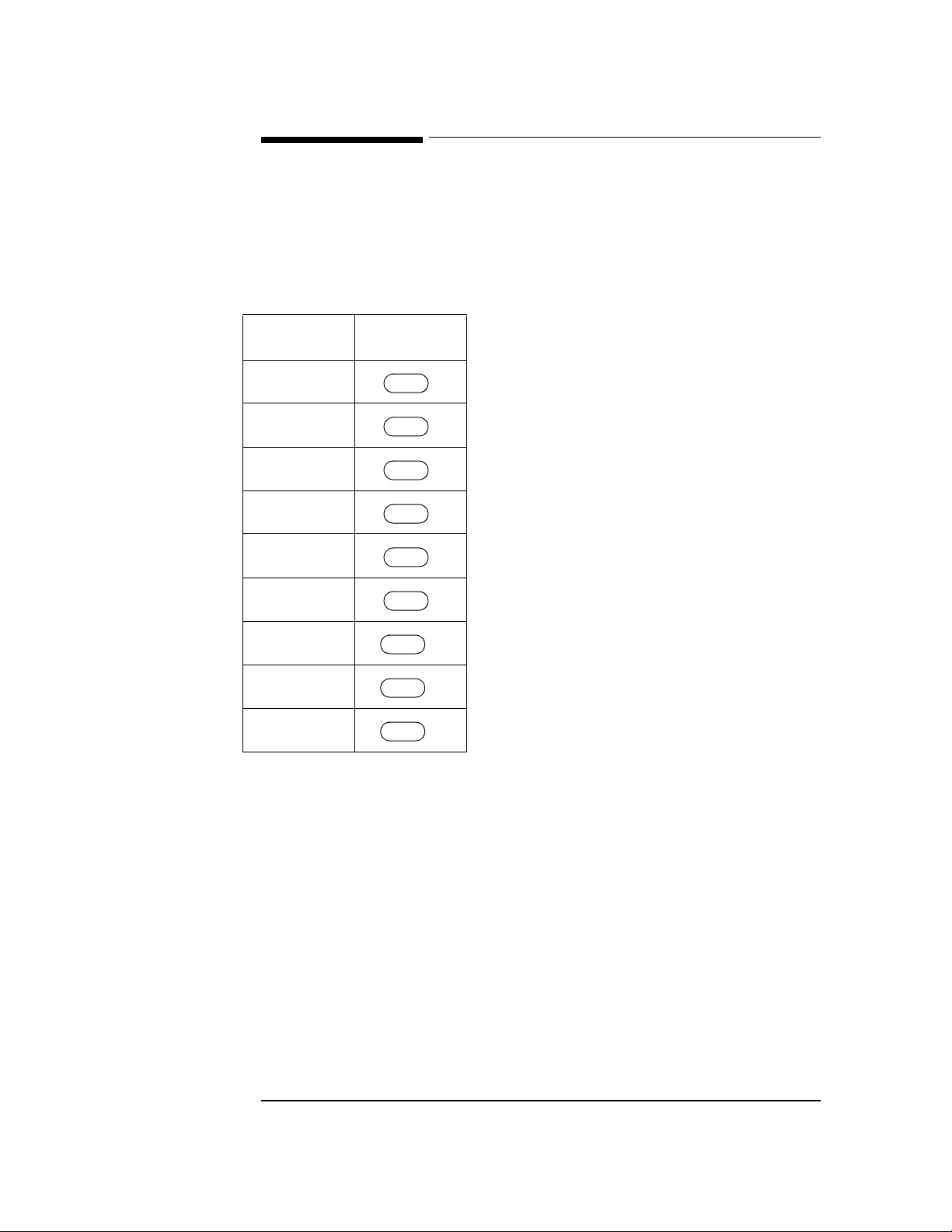
Table 2-9 Language Key Combinations
Language PageWriter
200/200i/300pi
English
French
German
Dutch
Spanish
Italian
Swedish
Finnish
Norwegian
$OW
$OW
$OW
$OW
$OW
$OW
–0
–1
–2
–3
–4
–5
–6*
–8*
–9*
*Only available on certain models.
2-16
Page 41

Resetting the Cardiograph to the Factory Default State
2Resetting the Cardiograph to the Factory Default State
Resetting the cardiograph sets the Auto ECG report counter to 0, and resets the
PageWriter 200/200i/300pi configuration to the factory default.
Resetting the PageWriter 200/200i/300pi
To reset the PageWriter 200/200i/300pi perform the following steps:
1. Using Table 2-9, turn the cardiograph On in a language different from the current lan-
guage.
2. The cardiograph is now reset to the factory default state.
3. If it is necessary to operate the cardiograph in the original language, turn the cardio-
graph to Standby, then turn the cardiograph On using the appropriate key combination from Table 2-9.
Resetting the PageWriter 100
To reset the PageWriter 100 perform the following steps:
1. Turn the cardiograph to Standby.
2. Press and hold and while turning the cardiograph on.
&RS\
3. Turn the cardiograph to Standby.
4. Press and hold and while turning the cardiograph on.
&RS\
5. The cardiograph is now reset to the factory default state.
3DJH$GYDQFH
&KDUW6SHHG
2-17
Page 42

Preventive Maintenance
CAUTION
CAUTION
2Preventive Maintenance
Routine maintenance of the cardiograph consists of cleaning and inspection. This should
be done as needed.
The cardiograph does not require lubrication. Lubricating any part of the cardiograph
could damag e it or diminish its performance.
Care and Cleaning
The outside surfaces of the cardiograph and its accessories (except the patient cable) can
be cleaned by mild soap and water or isopropyl alcohol. The patient cable cannot be
cleaned with isopropyl alcohol. The patient cable can be cleaned only with mild
disinfectant or soap and water.
Cleaning the Cardiograph
1. Unplug the power cord and ensure that the cardiograph is in Standby mode (the dis-
play is off).
2. Wipe the external surfaces of the cardiograph with a soft cloth dampened with mild
soap and water or isopropyl alcohol. Avoid applying cleaning fluids to cable connectors.
Do not use any strong solvents or abrasive cleaning materials.
Do not spill any liquids on the surface of the cardiograph. Service the cardiograph
immediately if any liquids spill on the surface.
Do not use any of the following to clean the cardiograph:
• Acetone
• Chlorine bleach
• Ammonia-based cleaners
• Iodine-based cleaners
• Phenol-based cleaners
• Ethylene oxide sterilization (ETO)
• Autoclave
2-18
Page 43

Preventive Maintenance
CAUTION
CAUTION
Cleaning the Keyboard Overlay
1. Carefully insert a small flat-bladed screwdriver into the notches at the front edge of
the keyboard overlay and pry the front edge of the keyboard overlay up. Refer to Figure 2-3.
2. Repeat with the rear notches of the keyboard overlay and remove the overlay.
Figure 2-3 Removing the Keyboard Overlay
A. Notches
Do not wash the keyboard overlay in hot water. Do not attempt to clean the keyboard
overlay in a dishwasher.
3. Rinse off the keyboard overlay and thoroughly dry it.
The rubber keypad and/or keyboard assembly may be damaged if any key or LED
becomes trapped under the overlay while replacing the overlay. Make sure each and ever y
key and LED comes through its h ole in the overlay b efore snapp ing the over lay into p lace.
4. Align the overlay with each of the keyboard keys and LEDs. Position your thumbs
along the front edge of the overlay near each end. Apply pressure on the overlay
toward the rear of the unit and then press down on the overlay in one continuous
motion. The front of the overlay should now be snapped into place. Snap the rear of
the overlay into place.
2-19
Page 44

Preventive Maintenance
CAUTION
Cleaning the Digital Array Printhead and Paper Sensor
If you use Hewlett-Packard recording paper, you should not have to clean the printhead
for the life of the product. If you need to clean the printhead, this is the procedure to
follow. These are the materials required:
• Foam swabs — Hewlett-Packard part number 9310-0468 or 9300-0767
• 90% Isopropyl Alcohol — Hewlett-Packard part number 8500-0559 or equivalent
• Dry, lint-free tissue — Kimwipes® or Hewlett-Packard lint-free wipes (Hewlett-Packard
part number 92193W)
To clean the printhead:
Touch the equipotential connector on the back of the cardiograph to discharge any static
electricity stored on your skin before touching the printhead. The printhead can be
damaged by static electricity.
1. From the front of the cardiograph, unlatch and open the paper door. The printhead is
to the right under the paper blade, behind the ESD brush (see Figure 2-4).
Figure 2-4 Cleaning the Digital Array Printhead.
A. Printhead
B. Paper Sens or
2-20
Page 45

Preventive Maintenance
CAUTION
2. Wipe the printhead with a foam swab dipped in 90% isopropyl alcohol. Scrub until all
visible residue is removed.
3. Dry the printhead with a clean lint-free tissue.
To clean the paper sensor lens:
1. From the front of th e cardi og raph , un lat ch and o pen the p a per d oor . The pap er s ens or
lens is to the right under the printhead (see Figure 2-4).
2. Lightly wipe the paper dust off of the paper sensor lens with a dry foam swab. Do not
use alcohol.
Cleaning the Electrodes and Cables
Clean the reusable electrodes and patient cable with a soft cloth moistened with a
recommended disinfectant or cleaning agent from the following list:
• Cetylcide® (may discolor cable)
• Cidex®
• Lysol® Disinfectant
• Lysol® Deodorizing Clean er (may discolor cable)
• Dial® Liquid Antibacterial Soap
• ammonia
• 409® (may discolor cable)
• 10% solution of Clorox® in water (may discolor cable)
• Murphy® Household Cleaner, or
•Ves-phene II®.
Wring any excess moisture from the cloth before cleaning.
• Do not clean the patient cable with alcohol. Alcoho l can cau se the p l astic to bec ome brittle and may cause the cable to fail prematurely.
• Do not autoclave the cable or use ultrasonic cleaners.
• Do not immerse the patient cable.
• Do not use abrasive materials to clean metal surfaces—scratches on them can cause artifacts on the ECG report.
• Do not expose the connectors to liquids, especially the 15-pin connector.
2-21
Page 46

Caring for the Battery
CAUTION
NOTE
NOTE
2Caring for the Battery
The battery must be installed for proper operation of the cardiograph. Even if the
cardiograph is plugged into AC power, it cannot print an ECG report without the battery.
For information about removing or replacing the battery, refer to Chapter 5, Removal and
Replacement.
The sealed lead-acid battery used in the PageWriter 100, 200, and 300 family of
cardiographs will provide optimum life when the unit is continuously connected to AC
power and fully charged after each use. A depleted battery requires 16 ho urs of continuous
charge time to fully charge. Because it is not always possible to allow a full charge cycle
between uses, the cardiograph was designed to charge a depleted battery to 90% of its
capacity in approximately seven hours.
Repeated undercharging of the battery will damage the battery and reduce battery life.
Hewlett-Packard recommends that the cardiograph be plugged into AC power whenever
possible to maximize battery life.
Battery life varies depending on frequency of use and maintenance. For improved battery
life, keep the cardiograph plugged in when not in use. If th e battery has been f ully charged
and requires recharging after a few ECGs, consider repl acing it. Use only HP battery, p art
number M2460A.
Battery should be removed from unit and placed in storage if the cardiograph will not be
used for more than three months.
Storing the Battery
To prepare the battery for storage, charge it in the cardiograph for 16 hours. Remove the
battery and store it in a cool, dry location. Recharge a lead-acid battery in storage for at
least 16 hours every six months. This ensures that the battery does not completely
discharge while in storage. The battery’s shelf life is longer with cooler temperatures, but
do not store below freezing.
2-22
Page 47

Caring for the Battery
Safety Tests
The safety tests listed below are performed at the time of manufacture to assure
compliance with these standards: IEC 601-1, IEC 601-2-25, UL 544, and CSA 22.2 No.
125.
• Chassis-to-ground resistance
• Ground wire leakage current
• Enclosure leakage current
• Patient lead leakage current (source leakage) to ground
• Leakage current between patient leads
• Patient lead leakage current (sink current) with line voltage applied
Perform these tests as part of your preventive maintenance program, and after any
corrective maintenance to assure compliance with the named standards.
To perform these tests, use a safety tester or analyzer designed specifically for this
purpose. Follow the manufacturer’s operating instructions.
Record results as indicated in the Performance Verification Matrix.
2-23
Page 48

PageWriter 100, 200/200i, and 300pi Series Performance Verification Matrix
2PageWriter 100, 200/200i, and 300pi Series Performance
Verification Matrix
The following Performance Verification matrix lists all the tests and inspection
procedures which must be per formed on the M1 770A, M1771A, or M17 72A cardiog raphs
after servicing. Instructions for executing each test or inspection are described in this
manual.
Table 2-10 summarizes performance verification for the PageWriter 300pi/200o/200/100
cardiographs; includin g t est name, tes t or i nsp ect i on to perform, expected test results, and
data to record. Functional tests include ROM/RAM test s, transm ission tests, ECG FrontEnd tests, Flash Memory tests, Display tests, indicator LED tests, printer and keyboard
tests. Simulated ECG and Safety testing are also required.
Table 2-10 Performance Verification: PageWriter 300pi/200i/200/100 (M1770A, M1771A, M1772A)
Test Block Name
Test or "Inspection" to
Perform
Expected (Passing)
Test Results
Data to
Record
x=p (pass) or
f (fail)
Visual Inspection (V) Look for:
• Worn or damaged power cord
• Mechanical damage
• Corroded or damaged reusable
electrodes
• Loose or missing hardware
• Worn printer drive gear
• Worn or damaged patient cable
ower On Self Test
P
(PO)
Power on the unit
• For M1770A, M1771A - watch
display for error code
• For M1772A - watch keypanel
LEDs for indication of error code
(refer to the Troubleshooting sec-
tion of the Service Manual for a
list of codes)
Inspected parts appear
intact and undamaged
• the display should show
a three lead screen, with
no error codes
• the LEDs will momentarily light and then indicate the configuration, no
blinking light should be
seen
V:x
example: V:p
PO:x
example: PO:p
2-24
Page 49

PageWriter 100, 200/200i, and 300pi Series Performance Verification Matrix
Table 2-10 Performance Verification: PageWriter 300pi/200i/200/100 (M1770A, M1771A, M1772A)
Test Block Name
Extended Sel f Te s t
Test or "Inspection" to
Perform
Expected (Passing)
Test Results
Data to
Record
x=p (pass) or
f (fail)
Function Tests (F) Run Extended Self Test; verify:
•ROM-1
•ROM-X1 (for A05 & A10)
•RAM
•GA
•SIO(for A05 & A10)
• MODEM (for A05 & A10) with
(M1770-87909) test tool attached)
•ROM-2 (for M1770 & M1771)
•ROM-X2 (for A05 & A10)
• NVRAM
•ECG FE
• REMOTE (for future use)
•FLASH1 (for A05 & A10 option)
•FLASH2 (for future use)
"OK" for tests applicable to
the device and the device’s
options
Note: ROM-2 will be "OK"
for A.05.06 or later
F:x
example: F:p
Display test (D)
for M1770A &
M1771
Indicator Light Test
(L)
for M1772
Verify the following patterns:
• all pixels lit to create a black
screen
• no pixels lit to create a white
screen
• scrolling vertical bar fro m left to
right
Verify:
• indicator lights turn on and off
• all lights flash briefly
No burned pixels, no random lines on display, no
permanent patterns at normal contrast, no LCD
flicker
All indicator lights are
turned on and off individually; all lights flash briefly.
D:x
example: D:p
L:x
example: L:p
2-25
Page 50

PageWriter 100, 200/200i, and 300pi Series Performance Verification Matrix
Table 2-10 Performance Verification: PageWriter 300pi/200i/200/100 (M1770A, M1771A, M1772A)
Test Block Name
Test or "Inspection" to
Perform
Expected (Passing)
Test Results
Data to
Record
x=p (pass) or
f (fail)
Printer Test (P)
for M1772
eyboard Test (K) Depress each key For M1770A/M1771A,
K
Verify:
• straight diagonal lines
• even spacing between diagonal
lines
• consistent print qualit y
• consistent width between and
length of timing tics
• accurate rendition of all characters
• clean stepped bars with no drop
out in black areas
• all lights flash briefly
All criteria visually verified.
character displayed is correct or function operates
properly.
For M1772A, the corresponding LED lights and
turns off.
P:x
example: P:p
K:x
example: K:p
Simulation
ECG
(ECG)
Connect a 12 Lead Patient
Simulator to the Patient Cable and
print a 12 lead ECG. Visually
analyze the printout.
2-26
Trace activity in all 12
leads; no notable distortion
or noise; cal pulses of
proper duration and amplitude.
ECG:x
example: ECG:p
Page 51

PageWriter 100, 200/200i, and 300pi Series Performance Verification Matrix
Table 2-10 Performance Verification: PageWriter 300pi/200i/200/100 (M1770A, M1771A, M1772A)
Test Block Name
Test or "Inspection" to
Perform
Expected (Passing)
Test Results
Data to
Record
x=p (pass) or
f (fail)
System Safety (S)
Use Safety Analyzer
Check:
Chassis-to-Ground Resistance
Groundwire Leakage Current
(Normal condition)
Groundwire Leakage Current
(Single Fault)
Patient Lead Leakage Current
•Source (Normal Condition)
•Source (Single Fault Condition)
•With Mains on applied part
(Single Fault Condition)
•Auxiliary (Normal Condition)
•Auxiliary (Single Fault Condition)
Indicate Applicable Safety
Standard as follows:
Note: All leakage current test are
Normal and Reverse Polarity
Conditions
<
200 mΩ aaa
500 uA (<300uA UL) bbb
<
1000 uA cccc
<
10 uA dd
<
50 uA ee
<
50 uA (< 20 uA UL) ff
<
10 uA gg
<
50 uA hh
<
i=I for IEC i
i=U for UL
S:aaa,bbb,ccc,dd,
ee,ff,gg,hh,i
example:
S:09,400,900,8,4
0,30,8,40,I
For the above - record the worst
case value for multiple lead
measurements.
Note: When recording test results, separate tests by a semi-colon(;). For example: V:p;PO:p;F:p;
D:p;L:p;P:p;K:p;ECG:p;S:90,400,900,8,40,30,8,40,I
2-27
Page 52

PageWriter 100, 200/200i, and 300pi Series Performance Verification Matrix
2-28
Page 53

Theory of Operation
This chapter contains an over view of t he cardiograph operatio n, and circuit description s of
the major subassemblies. Except as noted, the information in this ch apter applies to the
M1770A PageWriter 200i/300pi, the M1771A PageWriter 200, and the M1772A
PageWriter 100.
The last section in this chapter describes the Option #A05 printed circuit assembly.
2Operational Overview
This overview covers two areas of cardiograph operation: the path that ECG data follows
from collection to display, and the cardiograph’s power-on/power-off sequence.
ECG Data Path
Analog ECG data are collected through the patient cable to the ECG Front End on the
CPU Assembly Board in the cardiograph. The ECG Front End performs analog-to-digital
conversion before sending the data to the System Gate Array. The System Gate Array
receives the ECG data and processes it. The data may be interpreted (200i/300pi only),
displayed (200/200i/300pi only), printed, or stored in system RAM. PageWriter
200/200i/300pi car diographs e quipped wi th Optio n #A05 can als o store up to thi rty ECGs,
and transmit ECGs to TraceMaster ECG Management Systems, other PageWriter
cardiographs, facsimile machines, and other HP equipment.
Power-on and Power-off Sequences
When the cardiograph is turned on or off, it follows a sequence of events in applying
power to or removing power fro m its circuits. The System Gate Array c ontrols this
sequence because the System Gate Array remains powered up even when the cardiograph
is in Standby.
Power-on
The system gate array is powered from a supply which is always turned on (Unswitched
5V). When it detects that the key has been pressed, it sends the ENBL5V
signal to the power supply to turn on the Switched 5V supply and reset the other circuitry.
When the CPU is taken out of reset mode, the processor begins execution of the software
located in ROM. The software sets up the system, decides what type of keyboard is
attached, calibrates the ECG Front End, and initializes the display, if present.
2Q6WDQGE\
3-1
Page 54

Circuit Descriptions
Power-off
The power-off sequence is software controlled. The power-off sequence is initiated when
2Q6WDQGE\
the key is pressed, battery time-out occurs, or the battery is too low to
continue. At power-off, the software begins housekeeping tasks such as turning off the
printer, disabling the keyboard, and turning off the display, if present. When the
housekeeping is complete, the software instructs the Sy stem Gate Array to turn off the
Switched 5V supply. The details of how the power supply shuts down are described later
in this chapter in the power supply description.
2Circuit Descriptions
The M177XA family of cardiographs has a common set of major subassemblies: a Power
Supply board, a CPU Assembly board, and a Keyboard (including a Display on the
200/200i/300pi). The design also includes a thermal print mechanism. The power supply
design requires a battery for all operations. Option #A05 adds a storage and transmission
board.
Option #A10 adds an interface board for communication to the HP StressWriter system.
The CPU assembly is the same for all cardiographs except that some models of the
PageWriter 200/200i CPU assembly have an extra ROM to accommodate the ECG
measurements and interpretation software. The subassembl ies, including the CPU
assembly and its major circuit groups, are shown in Figure 3-1.
3-2
Page 55

The Patient Cable
Figure 3-1 Simplified System Block Diagram
3The Patient Cable
The patient cable used in the PageWriter 100/200/200i/300pi family is a passive design
using no active components. The leadwires each contain a resistor designed to protect the
instrument from the energy used in defibrillation.
The cable simply conducts the analog ECG data from the patient to the ECG Front End on
the CPU Assembly Board.
3-3
Page 56

CPU Assembly
3CPU Assembly
This discussion of the CPU assembly covers th e following circuits:
•CPU
• System Gate Array
• Serial EEROM
• System Memory (DRAM)
•ROM
• Printer Gate Array/SRAM
• Analog/Digital Converter
• System Expansion Connector
The block diagram in Figure 3-2 shows these circuits and how they interconnect.
Figure 3-2 CPU Block Diagram
Keyboard
LED(s)
System
Oscillator
DRAM
256K X 16
VBATT
VPRINT
Therm
and
Row/Col Addr.
Intel
80960SA
CPU
High
Analog/
Digital
Converter
Display
(PW 200)
Reset
Low Address/Date
Address
Data
Control
ROM 1
256K X16
Clock
Printer
Gate
Array
Serial
EEROM
1K bit
System
Gate
Array
Low
ECG
Front
End
Real-Time
Crystal
Address
ROM 1,2
ROM 2
(2) 512K x 16
256K X 16
(1) 2MB x 16
Based on Serial #
Thermal Printhead
Data
Control
Expansion
Connector
or
3-4
Printer
SRAM
Motor
Driver
Motor
M177X3-2
Page 57

CPU Assembly
CPU/System Oscillator
The CPU (Central Processing Unit) is the processing engine for the instrument. The
microprocessor used is the Intel 80960SA, a 32 bit microprocessor with a 32-bit address
bus and a 16-bit external data bus (32 bit internal data bus). The lower 16 bits of the
address bus are multiplexed with the data bus; these lines are de-m ultiplexed by the
System Gate Array. The processor operates at 16 MHz off of a 32 MHz System Oscillator.
The data and address buses are shown in the above block diagram.
Instructions for the CPU are stored in RAM and ROM external to the CPU.
System Gate Array/Real-Time Crystal
The System Gate Array provides the following functions:
• ECG Front End control
• Interrupt control
• DMA for ECG data
• DMA for LCD data
• System reset circuitry
• Watch-dog circuitry
• Real-time clock (including driving the external Real-Time crystal)
• DRAM RAS and CAS generation and refresh
• Interface to the Serial EEROM
• Address decoding for the Printer Gate Array and ROMs
• Keyboard scan and LED drive
• LCD control (for the PageWriter 200/300 series)
ECG Front End Control
The ECG Front End control interface consists of serial command data to the front end, and
serial data (ECG or status) from the front end.
The input command data cons ists of a singl e 24-bi t word cont aining an address field an d a
control field. Depending on the data in the address field, the contents of the control field
apply to either
• configuring each individual front end integrated circuit,
• configuring both front end integrated circuits together as a system, or
• setting the calibration value of the front end integrated circuit
Interrupt Control
The interrupt control interface manages two of the four processor interrupt signals. The
processor interrupt signal names are nINT0, INT1, INT2, and nINT3. nINT0 and nINT3
are controlled by the System Gate Array. INT1 is for interrupts from an expansion board
(such as the Option #A05 storage and transmission board) connected to the System
Expansion Connector. INT2 is controlled by the Printer Gate Array.
3-5
Page 58

CPU Assembly
DMA for ECG Data
The System Gate Array receives data from the ECG Front End in serial form. When 16
bits have been received, the System Gate Array places the CPU in a HOLD state, and
generates the necessary address and control signals needed to write the data into the
System Memory (DRAM). After the data are successfully written, the HOLD state is
discontinued and the CPU resumes its processing. The System Gate Array can also deliver
interrupts to the CPU to indicate when a frame (1 msec) and/or a buffer-full (10 0 msec) of
data have been written into memory.
DMA for LCD Data
In the 200/200i/300pi, the System Gate Array reads 16 bits of LCD data f rom System
Memory (DRAM) and delivers it to the LCD for display at an approximately 8 µsec
intervals. The process of reading the 16 bits is to first place the CPU in a HOLD state, then
to generate the necessary address and control signals to read th e data, then to discontinue
the HOLD state and allow the CPU to resume processing. The data are delivered one
nibble (4 bits) at a time to the LCD, after which time the HOLD cycle is repeated.
System Reset Circuitry
At a normal power on (pres sing ), the CPU and most other circuits are reset to
2Q6WDQGE\
a known initial state by the internally generated s ign al NRESET. This signal is created
within the System Gate Array, which is always active and operating.
Removing all power resets all circuits, including the S ys tem Gate A rray, via the signal
NNEW5V. Removing all power also resets the real-time clock and date.
Watch-dog Circuitry
The watch-dog circuit will turn off the instrument within 7-8 seconds unless periodically
reset by the control software.
Real-Time Clock
The real-time clock maintains the current date and time. This clock operates off the
cardiograph battery and will run as long as the battery is installed and charged.
DRAM RAS and CAS Generation and Refresh
Refresh of the DRAM is accomplished using a CAS (Column Address Strobe) before
RAS (Row Address Strobe) technique. RAS and CAS are DRAM control signals used to
latch the desired memory address location. A refresh of one row in the DRAM occurs
approximately every 15 µsec.
3-6
Page 59

CPU Assembly
NVRAM Interface
The NVRAM contains 1K bits of non-volatile storage for the cardiograph configuration.
Keyboard Interface
The passive Keyboard is scanned by the System Gate Array for keypresses. The LED(s)
are also driven by the System Gate Array. The software is responsible for determining
which keyboard is loaded and configuring the instrument for proper operation.
Display Control for PageWriter 20 and 300 Series
The display is a 240 x 128 dot super-twisted nematic Liquid Crystal Display module with
integrated driver circuitry. Its operation is controlled by the System G ate Array.
NVRAM
The NVRAM stores configuration information. It is written to by the System Gate Array
under software control and requires no power to retain its data.
ECG Front End
The ECG Front end is described in “ECG Front End”.
DRAM
The DRAM (Dynamic Random Access Memory) is a 256K x 16 bit read/write memory.
The System Gate Array prov ides t he multi plex ed addres s in format ion, generates RAS an d
CAS, and provides the timing and control required for memory transfers from and to the
CPU. The DRAM connects directly to the Data bus.
ROM-1 and ROM-2 Address Space
Cardiographs with serial number prefix CNA, CNB, CNC, or 3807A or earlier have a
Control Board with space for two ROMs (Read Only Memory) to provide data and
instructions for the CPU. In addition, the Control Board expansion connector and System
Gate Array provide for additional expansion. Each ROM contains 512K x 16 bits of readonly memory.
Cardiographs with serial # prefix CND have one 2MB EPROM on the control board
which defines the ROM1 and ROM2 address spaces. Th e ROM contains 2MB x 16 bits of
read-only memory.
Printer Gate Array/SRAM
The printer gate array is the principal component o f the prin ter con trol circui try. I t bu ffers
print data from the system, and status data going to the system. It also controls printer
3-7
Page 60

CPU Assembly
timing and the printer RAM, regulates motor speed, monitors printhead temperature,
monitors the battery condition, and provides the in terface between the printer and the
system CPU.
The printer RAM consists of 32K of static RAM used to store printer data and the printer
look-up table data. The look-up table data is used to compensate the motor drive signals
and the printer enable pulses for variations in the operating environment. The look-up
table data also includes the motor settings and the motor ramp-up profile.
Motor Driver
The phase signals from the printer gate array enable the motor driver circuit, which
switches current through the stepper motor in the paper transport.
Analog/Digital Converter
This 8-bit parallel A/D converter measures printhead temp erat ure, battery voltage, and
printer supply voltage.
Thermal Printhead
The thermal printhead is a line of 1728 printing elements. Each printing element is a
resistive heater. Heat from these elements blackens the thermoreactive paper, creating an
image. A 1728-bit shift register (on the printhead) contains the dot data for the print line.
Data is serially loaded into the shift register, then latched so that data for the next line may
be shifted into the head while the present line prints. A strobe signal enables printing. The
pulse width of the strobe is adjusted to compensate for different recording speeds and
variations in supply voltage, average resistance, and temperature. The temperature is
sensed by a thermistor on the printhead heat sink.
System Expansion Connector
The System Expansion Connector provides the instrument with future expansion
capability, such as Option #A05, #A10.
3-8
Page 61
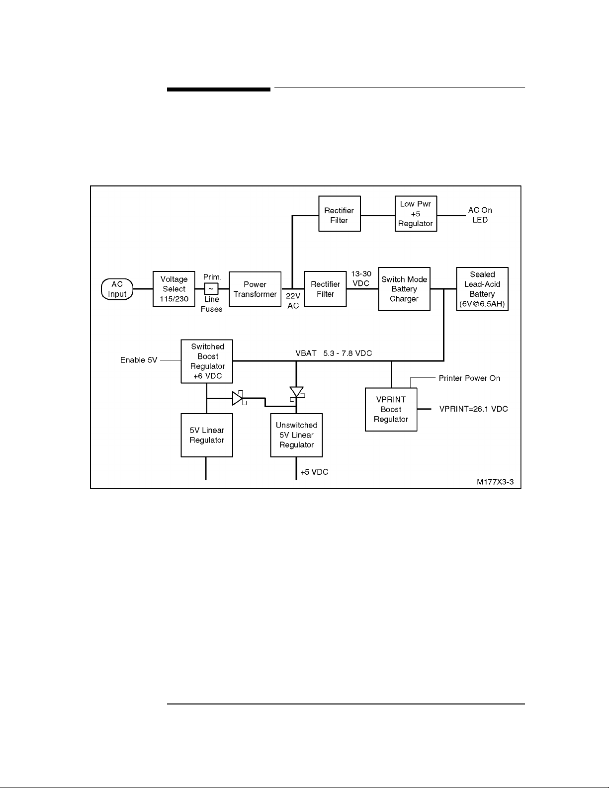
Power Supply
3Power Supply
The Power Supply connects the instrument to the AC line to charge the b attery an d po wer
the circuitry. It conditions and regulates all power supplied to the Main Bo ard.
Figure 3-3 Power Supply Block Diagram
Voltage Selector
The voltage selector connects the line input to the proper windings on the Power
Transformer to produce the correct secondary voltage at the output of the Transformer.
Primary Line Fuses
The Primary Line Fuses protect the power supply from catastrophic failures.
Power Transformer
The power transformer reduces the input voltage to 22V AC (nominal).
3-9
Page 62

Power Supply
Rectifier/Filter
This circuitry rectifies and filters the AC voltage to produce a DC vol tage for the rest of
the power supply.
Switch-Mode Battery Charger
The battery charger converts the output from the Rectifier/Filter to one of two levels. The
first level is called the float voltage and equals 6.85 VDC (nominal at 25 C). The second
level, called the overcharge voltage, is 7.4 VDC (nominal at 25 C). Both of these levels
are temperature compensated. The charger is capable of delivering a maximu m of 1.5A at
its output in either the float mode or overcharge mode. The charger is a pulse width
modulated switching type that has a nominal switching frequency of 100 KHz.
The charger enters the overcharge mode when any one of the following conditions are
met: VBAT drops below 6.1V (nominal at 25 C), the instrument is turned on, a print
operation starts, or the instrument is plugged into AC power. The charger changes into the
float mode when the current into the battery is less than 80 mA.
Battery
The battery is a lead-acid 6 volt unit, providing 6.5 Amp-Hours of current when fully
charged.
VPRINT Boost Regulator
The VPRINT Boost Regulator converts its inpu t voltage to the 26 V supply required for
operation of the thermal printhead.
Switched +6V Boost Regulator
The boost regulator is activated by turning the instrument On. It eliminates the heavy
transients induced into the +5V supplies by the printing subsystem during normal printing.
The output from this switching regulator is the input to both of the +5V Linear Regulators
when the instrument is On. When the instrument is in Standby mode, the battery po w ers
the unswitched +5V Linear Regulator.
5V Linear Regulators
There are two regulators, both linear, described here. The first is the unswitch e d +5V
regulator that provides power for circuitry active in the Standby mode. The System Gate
Array circuitry active in Standby mode includes the real time clock.
The second +5V Linear Regulator provides the bulk of the operating power for the rest of
the instrument when the instrument is On. This regulator is off when the instrument is in
Standby mode.
3-10
Page 63
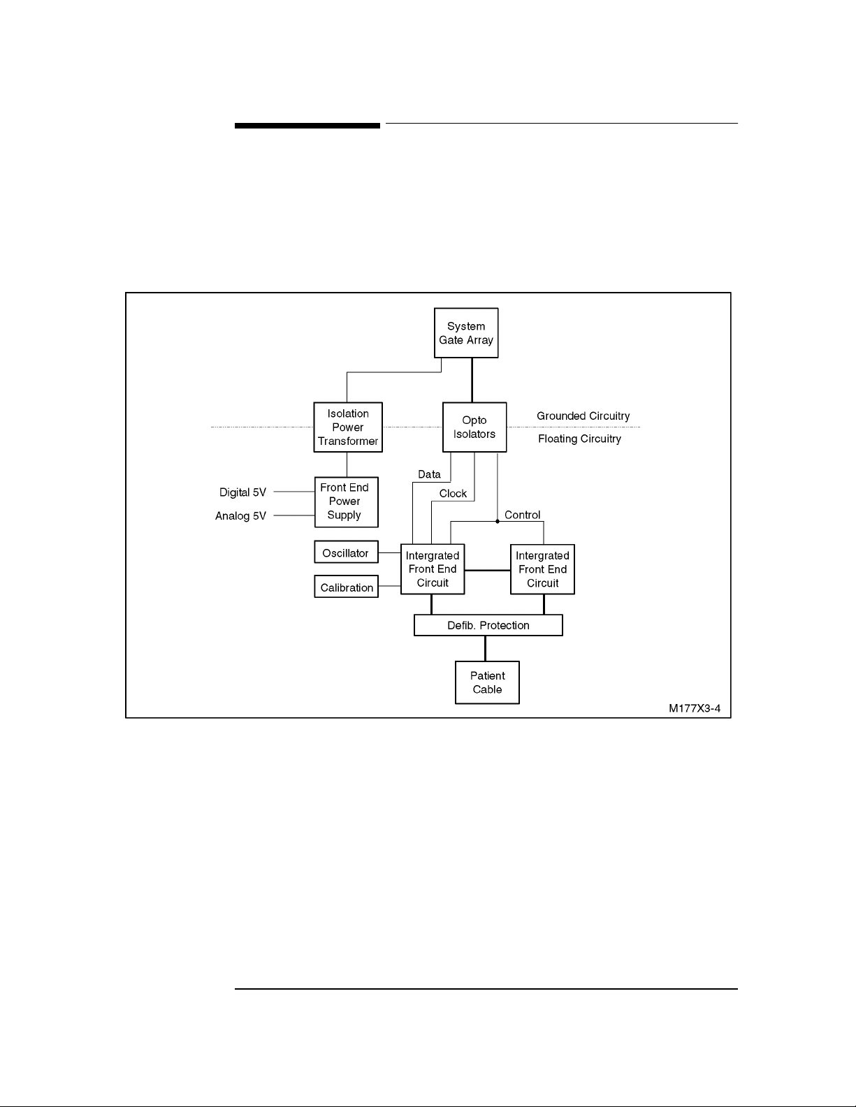
ECG Front End
3ECG Front End
The ECG Front End provides the interface between the system and the patient. It
electrically isolates the patient to prevent excess leakage current, protects the system from
defibrillator and electrostatic discharges, and converts the analog electrical signals present
on the patient to digital samples for processing and printin g.
Figure 3-4 Front End Block Diagram
Isolation Power Transformer
The Isolation Power Transformer passes power to the ECG Front End and electrically
isolates the patient-connected circuitry of the Front End from the rest of the instrument.
Front End Power Supply
The Front End Power Supply delivers separate, regulated power at 5V to the digital and
analog circuitry.
3-11
Page 64

ECG Front End
Opto-Isolators
Opto-Isolators pass the digital sample data from the patient-connected circuitry to the rest
of the instrument, providing electrical isolation.
Integrated Front End Circuits/Oscillator
The Integrated Front End Circuits sample the patient leads at 4.096M samples per second
per lead. The data are then filtered to 12 bits at 5 µV/LSB and 2 msec per sample. The
circuits include protection circuitry, gain, A/D conversion, and Oscillator control. These
circuits have a master/slave arrangement, with the master drivin g the Oscillator and
communicating all data to the System Gate Array through the opto-isolators.
Calibration
This circuitry is used to set ECG gain for the Integrated Front End Circuits.
Defibrillator Protection
Defibrillation Protection is provided by resistors in the patient cable combined with
circuitry in the Integrated Front End Circuits.
3-12
Page 65

Storage and Transmission (Option #A05 0nly)
3Storage and Transmission (Option #A05 0nly)
The Option #A05 PC assembly plugs into the cardiograph expansion slot, where it
connects to the main PC assembly as shown in Figure 3-1. The cardiograph main board
provides power and access to the cardiograph system electronics. The Option #A05 PC
assembly contains all the circuitry needed to store and transmit ECGs.
Figure 3-5 M177XA Cardiograph Connections to Option #A05 PC Assembly
Cardiograph
Power
Supply
Cardiograph
Main
Board
A05 Option
Board
RS-232
Connection
3-13
Page 66

Storage and Transmission (Option #A05 0nly)
Figure 3-6 Option #A05 PC Assembly Block Diagram
M177X
Expansion
Connector
Gate
Array
18.432 MHz
Oscillator
Address
Dual
UART
Serial Port
Connector 1
RS-232
Drivers
Serial Port
Connector 2
VPROG
Supply
ROM-X1
256K x 16
SYS Control
GA Control
ROM-X2
256K x 16
Data
FLASH 1
1M x 16
FLASH 2
1M x 16
M177XA Expansion Connector
The expansion connector on the Option #A05 PC assembly mates with the M177XA
cardiograph expansion connector. This connection provides the Option #A05 PC
assembly access to the cardiograph Address Bus, Data Bus, System Control Bus, and
power supplies .
Gate Array
The gate array integrates the following functions:
• Address decoding and chip selects for the expansion ROMs (ROM-X1 and ROM-X2)
• Flash memory controller
• Interface to the Dual UART
ROM-X1, ROM-X2
ROM-X1 and ROM-X2 are ROMs provided for the cardiograph firmware expansion. The
cardiograph CPU controls and execute the firmware in these ROMs.
3-14
Page 67

Storage and Transmission (Option #A05 0nly)
Flash1, Flash2
FLASH1 and FLASH2 are 1M x 16 bit flash ROMs. The gate array provides control and
timing functions required to interface these parts to the address and data bus. FLASH1 is
used for non-volatile ECG stora ge . FLASH2 is provided for expans ion memory. It is not
normally present on the Option #A05 printed circuit assembly.
VPROG Power Supply
The VPROG power supply provides a 12V DC programming voltage to FLASH1 and
FLASH2 during erase and write operations. The source for the supply is the cardiograph
printhead supply voltage, which is turned on an d of f by the software. The VPROG sup ply
circuit contains a 12V linear regulator that drops the printhead supply voltage to the
required 12 volts for FLASH1 and FLASH2.
Dual UART
The Dual UART (Universal Asynchronous Receiver/Transmitter) contains two
independent UARTs with the following capabilities:
• modem control
• baud rate generator
• 16 byte FIFO (first-in-first-out) buffer
Each UART is used to implement an RS232 port by translating between serial and parallel
data.
18.432 MHz Oscillator
The 18.432 MHz Oscillator provides a clock for the internal functions of the Dual UART.
RS232 Drivers
The RS232 Drivers perform the voltage level translation between TTL logic level signals
from the Dual UART and the +
10 volt RS232 signals.
Serial Port Connectors 1 and 2
These connectors are 9-pin D-subminiature connectors that are located at the back panel
of the cardiograph, and provide access to the two RS232 ports. The serial port marked
RS-232 is used for ECG transmission. The other serial port is reserved for future use.
The #A10 interface board also, provides storage and transmission capability in addition to
the HP StressWriter interface.
3-15
Page 68

Storage and Transmission (Option #A05 0nly)
3-16
Page 69

Troubleshooting
CAUTION
3Introduction
This chapter provides information for localizing cardiograph problems to the subassembly
level. This information is designed for use with the cardio graph’s Extended Self-test to
help you efficiently repair the cardiograph with a minimum of equipment.
3Maintenance Philosophy
The maintenance philosophy for the cardiograph is subassembly replacement.
Replaceable subassemblies are identified in Chapter 6, “Parts List”.
Individual component replacement should not be attempted outside of an authorized
Hewlett-Packard repair facility. Component level repair is extremely difficult due to the
extensive use of surface mount technology and the high parts density o n the circuit boards.
Unauthorized component replacement can impair cardiograph performance, compromise
patient safety, and jeopardize credit towards a replacement assembly.
3Test Equipment
The following test equipment is required to troubleshoot the cardiograph as described in
this chapter:
• A digital voltmeter such as the Hewlett-Packard E2373A hand -held multimeter.
• A 12-lead ECG simulator.
• A jumper wire with Pomona Micrograbber test clips or equivalent. Ordering information:
ITT Pomona 1500 East Ninth St.
P.O. Box 2767
Pomona, CA 91769
Sales: (909) 469-2900
4-1
Page 70

Test Tools
NOTE
NOTE
NOTE
3Test Tools
Two troubleshooting tools are provided with each instrument:
• patient cable test tool (M1770-87908)
• front end and transmission test tool (M1770-87909, Rev. B)
Patient Cable Test Tool (M1770-87908)
This tool is attached inside the battery compartment, beneath the battery. To locate it, open
the battery compartment door and lift the battery.
This tool is used to short the lead wires together to test lead wire integrity. To test the
leads, plug all ten lead wire posts into the holes o f the tool and print an ECG. If all leads
print clear, solid flat lines, the lead wires are intact.
Front End and RS-232 Port Test Tool (M1770-87909, Rev. B)
This tool is located on the lower side of the printer doo r. To remove it, o pen the printer
door and reach underneath it. The tool has two test plugs, one used to test the instrument
signal path, and one used to test the c ardiograph’s RS-232 port.
Testing the Instrument Signal Path
To test the instrument signal path, plug the larger connector into the patient cable
connector on the front of the cardiograph. Print an ECG. If the front end is operating
properly, all leads will show clear, solid flat lines with little or no no ise.
You can use the patient cable test tool and the front end test tool to isolate patient cable
problems and cardiograph problems.
Testing the Car d iograph’s RS-232 Port
To test the cardiog raph ’s R S- 232 po rt , p l ug t he smal l er connector into the RS-232 port, in
place of the modem. Run the extended self-test described in Chapter 2. The modem test
will pass if the cardiograph RS-232 port is operating properly. This can help differentiate
between cardi ograph problems, and cable or mode m problems.
You can use the front end and RS-232 port test tool to isolate modem problems and
cardiograph problems.
The RS-232 port test connector is available only on Revision B of the M1770-87909.
4-2
Page 71

The Error and Event Logging
$XWR
3The Error and Event Logging
The last error that was displayed can be printed by starting the Extended Self-test. The
error code is useful in di agno sin g what was last wro ng wi th the cardiograph. See “How to
Read the Extended Self-Test Report” in Chapter 2 for the location of the last error on the
Extended Self-test report.
The last 46 events recorded in the Events Log are also printed on the Extended Self-Test
Report for cardiographs equipped with Option #A05.
3Using Extended Self-test in Troubleshooting
The cardiograph’s Extended Self-test is a simple-to-use, looping test that gives you
pass/fail status for each of these major subassemblies:
• CPU assembly
•Printer
• Keyboard display (M1772A excluded)
• Modem (Option #A05 only)
Instructions for entering and using Extended Self-test are found in Chapter 2.
3How the PageWriter 100 Communicates Error Codes and
Messages
The PageWriter 100 uses its LEDs to communicate error codes and messages.
PageWriter 100 Error Code Communication
When an error is detected, all LED’s light for 1/2 second, then the LED’s above the error
code digits light in turn for 1/2 seconds each, beginning with the leftmost digit. For
example, error code 3527 will cause the following LED’s to blink in the order giv e n: 3
)LOWHU
, 5 , 2 , 7 (all Manual lead group LED’s).
9/HDGV
4-3
Page 72

Troubleshooting Tables
PageWriter 100 Error Message Communication
The PageWriter 100 communicates the following error messages with these corr esponding
LED’s:
Leads off All Manual lead group LED’s blink alternately with
$XWR
LED.
Check Paper Supply The current LED blinks.
Printer Door Open The current LED blinks.
3Troubleshooting Tables
The troubleshooting tables in this section help yo u to localize a fault and correct it. The
troubleshooting flowchart in Figure 4-1 guides you to t he troub leshooti ng table that covers
a particular functional area of the cardiograph.
Table 4-1 lists errors that can occur during operation and will appear only as numbers on
the display. The table defines and explains each error, and suggests one or more corrective
actions for each.
&KDUW6SHHG
&KDUW6SHHG
Figure 4-1 Troubleshooting Flowchart
Start
Powers up
Yes
Error displayed?
No
Patient Cable &
ECG Front End
ECG problems
See Table 4-3
CPU
System
inoperative
See Table 4-4
Printer
No paper
movement.
Poor print
quality.
See Table 4-5
No
Yes
Keyboard &
Display
Keys don’t
function or
garbled display
See Table 4-6
See Table 4-2
See Table 4-1
Storage
Cannot store
or retrieve
ECGs.
See Table 4-7
Transmission
Cannot send
or receive ECGs.
See Table 4-8
4-4
Page 73

Troubleshooting Tables
CAUTION
Before removing or inserting any board or connector, make sure AC power is off and the
battery is removed.
The error codes listed below appear on the extended self-test report in the last error
column or in the event log (Option #A05 only) described in Chapter 2.
Table 4-1 Error Codes
Error # Definition Corrective Action
1010, 1217, 1221, 5223 Memory allocation fault 1. Turn off, wait 30 seconds, turn on.
2. Retry the operation.
1100, 1102-1107, 1200,
5327-5331, 3515, 51 77
1101 ECG front end could not calibrate due to exces-
2000-2003, 5221 Power supply faul t. 1. Test t he power suppl y (refer to “Testing the Power
3517-3527 Adv is ory codes appear dur ing power-on and
3510, 7000, 7001 Defective keyboar d or keyboard cable Replace keyboar d i f t he e rr or persists.
3531 Defective FLASH memory. 1. Perform the extended self-test (refer to Chapter
5033-5077 Defec tive CPU assembly. 1. Turn off, wait 30 seconds, turn on.
5155 Defective UART. 1. Perform the extended self-test (refer to Chapter
Defective ROMs or other related hardwar e pr oblem on CPU assembly.
sive ambient noise.
indicate an ab normal cardiograph shutdown.
1. Turn off, wait 30 seconds, turn on.
2. Replace CPU assembly, if error code persists.
If the cardiograph uses softwar e release A.01.02,
modify the card i o graph using upgrade kit M1770-
89520.
Supply). Replace pow er supply if defect ive.
2. Inspect cabling between power supply and CPU.
3. Replace CPU assembly, if error code persists.
Turn off, wait 30 seconds, turn on.
2).
2. If the extended self-test fails, repl ace the Option
#A05 PCA.
2. Replace CPU assembly, if error code persists.
2).
2. If the extended self-test fails, repl ace the Option
#A05 PCA.
All other error codes Bad configuration. 1. Reset configuration. Refer to”Resetting the Car-
Defective CPU assembly
diograph to the Factory Default State.”
2. Replace CPU assembly, if error code persists.
4-5
Page 74

Troubleshooting Tables
2
Table 4-2 Power Supply and Battery
Symptom Possible Cause Corrective Action
AC indicator not lit. Power cord unplugged.
AC line voltage switch in wrong position.
One or both AC fuses are blown.
Power supply to CPU interface cables or key-
board cable not fully seated.
Bad power supply to CPU interface cable(s).
Bad keyboard circuit board.
Bad power supply .
Bad CPU assembly.
Cardiograph doesn’t run on
Battery connector is loose or defective.
battery, but runs on AC .
Low battery or defective battery.
Software has stopped.
Battery fuse is blown.
Battery charger is defective.
Cardiograp h w on’t power up
on AC or battery.
Power supply to CPU interface cables or keyboard cable not fully seated.
Power supply to CPU interface cable(s) is defective.
Software has stopped.
Keyboard circuit board is defective.
Power supply is defective.
CPU assembly is defective.
Plug in power co rd.
Move to correct po si tion.
Replace AC fuse(s).
Reseat cables .
Replace cable(s) .
Replace keyboard assembly.
Replace power suppl y.
Replace CPU assembly.
Make sure b attery connector is properly seated
and not defective .
Charge or replace battery.
Unplug from A C powe r. Rem ove ba tter y. Wai t
2 minutes. Reinstall battery and turn instrument on.
Disconnect the battery and visually inspect the
battery fuse on the b attery. Rep lace the battery,
if necessary.
Replace power sup ply assembly.
Reseat cables .
Replace the power supply to CPU interface
cable(s).
Unplug from A C powe r. Rem ove ba tter y. Wai t
2 minutes. Reinstall battery and turn instrument on.
Replace the keyboard assembly.
Replace power sup ply assembly.
Replace CPU assembly.
Battery does not charge. AC line voltage switch in wrong position.
Defective power supply.
Defective battery.
Battery capacity too low. Battery is not fully charged.
AC line voltage switch in wrong position.
Defective or worn- out battery.
Cardiograph turns itself off
while plugged into AC
power.
AC line voltage switch in wrong position.
Power supply to CPU interface cables or key-
board cable not fully seated.
Defective power supply.
4-6
Move to correct po si tion
Remove battery. Using a voltmeter, measure
for approximat el y 6. 8 V dc across the battery
connector in the unit. Replace power supply, if
absent.
Replace battery.
Fully charge battery.
Move to correct po si tion.
Replace battery.
Move to correct po si tion.
Reseat cables .
Replace power suppl y.
Page 75

Troubleshooting Tables
Table 4-2 Power Supply and Battery
Symptom Possible Cause Corrective Action
Low Battery light or Low
Battery message remains on
during extended self-test.
Low Battery light or Low
Battery message blin ks .
One or more power supply
voltages missing (see “Testing the Power Suppl y” at the
end of this chapter).
Low battery or defective battery.
Battery fuse is blown.
Battery charger is defective.
Low battery. Fully charge battery.
Defective regulator circuit( s). Replace power supply assembly.
Charge or replace battery.
Disconnect the battery and visually inspect the
battery fuse on the b attery. Rep lace the battery,
if necessary.
Replace power sup ply assembly
Table 4-3 Patient Cable and ECG Front End
Symptom Possible Cause Corrective Action
”Leads off” not indicat ed
when wire is off.
Dirty contacts on patient cable connector.
Defective or di rt y leadwire.
Defective ECG front end.
Ensure the contacts on the patient cable connector are clean and dr y. R eseat the patient cable
connector.
Clean leadwire. Re place pat ient cable if leadwire
defective.
Replace CPU assembly.
”Leads off” indicated w hen
wire is not off.
Poor electrode contact.
Defective lead wire.
Improve patient preparation.
Clean leadwire. Re place pat ient cable if leadwire
defective.
4-7
Page 76

Troubleshooting Tables
NOTE
Table 4-3 Patient Cable and ECG Front End
Symptom Possible Cause Corrective Action
Bad ECG:
Good calibr ation pulse in
channels where traces are not
good.
A lead is missing — dotted
line on trace.
Noisy lead(s): “AC” (regular
pattern) — for 60 Hz, 12
peaks/5 mm at 25 mm/sec;
for 50 Hz, 10 peak s/5 mm.
Faulty operator technique; poor electrode
contact
Defective lead wires.
Defective ECG front end.
Faulty operator technique; poor electrode
contact.
Defective lead wires.
Defective ECG front end.
Faulty operator technique; poor electrode
contact.
Patient or patient cable near AC power.
Lead wires may be pic king up interferenc e
from poorly grounded equipment near the
patient.
Refer to Table 6-2 in user’s manual.
Replace patient cable.
Replace CPU assembly.
Refer to Table 6-2 in user’s manual.
Replace patient cable.
Replace CPU assembly.
Refer to Table 6-2 in user guide.
Reposition patient ca bl e. Refer to Table 6-2 in
user guide.Try unplugging cardiograph from the
AC outlet.
Route lead wires al ong limbs and away fr om
other electrical equipment. Fix or move poorly
grounded equipme nt .
Patient cable is too close to the cardiograph
or other power cords.
Noisy leads: Muscle artifact. Patient is not relaxed or skin has been irri-
tated.
Low quality disp osable electrodes, leadwire
adapters.
Noisy lead(s): I, III, aVL LA l eadwire defec ti ve. Replace pat i e nt cable.
Noisy lead(s): II, III, aVF LL leadwire defective. Replace patient cable.
Noisy lead(s): I, II, aVR RA leadwire defective. Replace patient cable.
Noise in only one V lead. Faulty operator technique; poor electrode
contact.
Defective lead wires
Noise in general. Faulty operator technique; poor electrode
contact.
Defective lead wires.
Move the cardiogr aph away from the pa ti ent.
Unplug the cardiograph and operate on battery.
Unplug the el ectric bed.
Refer to Table 6-2 in User Guide.
Replace disposable electrodes or leadwire adapters.
Test with ECG simulator. Replace patient cable.
Refer to Table 6-2 in user guide.
Replace patient cable.
Refer to Table 6-2 in user guide.
Replace patient cable.
Remember that most noise results from poor patient-electrode connections or poor quality
electrodes. If noise persists after checking electrode placement and lead-electrode
connections, the noise may be due to poor quality electrodes. Some electro des have a shelf
life of 48 hours or less once the foil package is opened. Eliminate electrode placement,
connections, and freshness as the causes of the noise before replacing the patient cable.
4-8
Page 77
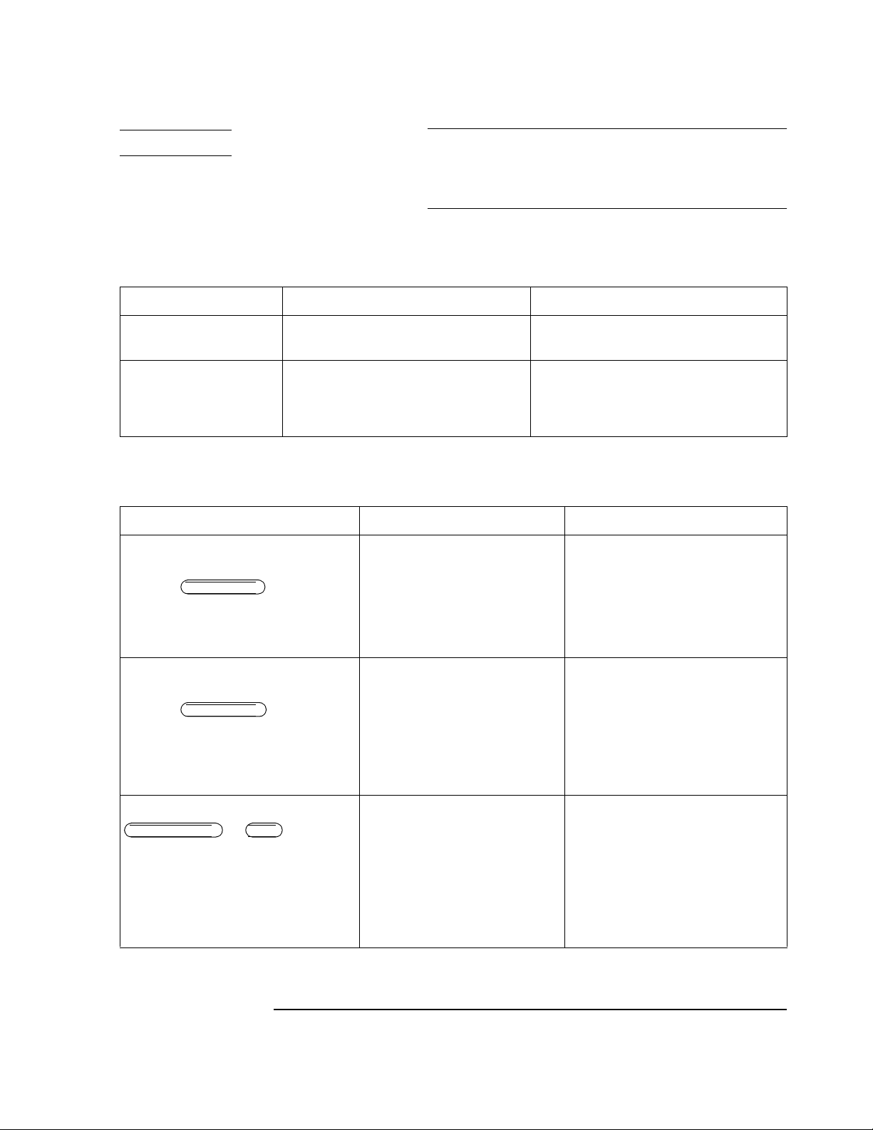
Troubleshooting Tables
NOTE
Chart Speed
Chart Speed
Page Advance
You can use the patient cable test tool and the ECG front end test tool to determine
whether a problem is caused by a poor patient to electrode connection, a defective cable or
a defective cardiograph. See the section titled “Test Tools” in this chapter for more
information about using the patient cable test tool.
Table 4-4 CPU Assembly
Symptom Possible Cause Corrective Action
System turns on but won’t
run. Power supply OK.
System won’t turn off. Software has stopped.
A cable is not fully seated.
Defective CPU assembly.
Defective CPU assembly
Reseat all cables.
Replace CPU assembly.
Unplug from A C powe r. R emove b atter y. Wait 2
minutes. Replace battery and turn unit on.
Replace CPU assembly.
Table 4-5 Printer
Symptom Possible Cause Corrective Action
Paper doesn’t move; printer error m essage
displayed
the current LED is flashing.
Paper moves then stops and displays error
message
the current LED is flashing.
Check paper supply or
Check paper supply or
A printer cable is not fully sea ted .
Defective sensor assembly.
Defective motor assembly.
Defective motor drive assembly.
Defective roller.
Defective roller.
Paper loaded incorrec tly.
Dirty sensor lens .
A printer cable is not fully sea ted .
Defective sensor assembly.
Defective sensor circuit.
Defective roller.
Replace paper or clear paper jam.
Reseat connectors J303 through J306.
Replace sensor ass embly.
Replace motor assembly.
Replace CPU assembly.
Replace printer d oor assembly.
Make sure cardiograph is loaded properly
with approved thermal paper.
Clean sensor lens.
Reseat connectors J303 through J306.
Replace sensor ass embly.
Replace CPU assembly.
Replace printer d oor assembly.
Paper stops in the wrong place after pressing
or . No error
Auto
message.
Wrong type of paper.
Sensor hole not cut out properly on
paper.
A printer cable is not fully sea ted .
Dirty sensor lens .
Defective sensor.
Defective sensor circuit
Make sure cardiograph is loaded properly
with approved thermal paper.
Remove defectiv e sheet of paper.
Reseat connectors J303 through J306.
Clean sensor lens.
Replace sensor ass embly.
Replace CPU assembly.
4-9
Page 78
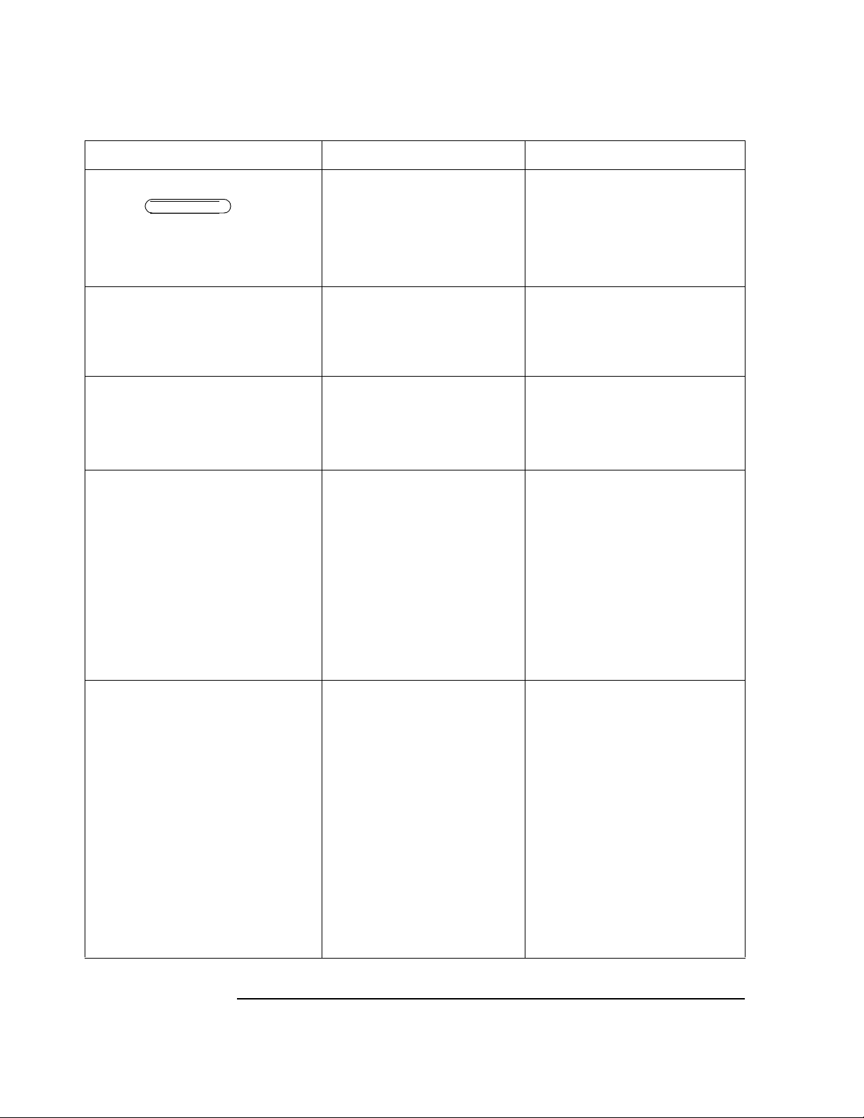
Troubleshooting Tables
Chart Speed
Table 4-5 Printer
Symptom Possible Cause Corrective Action
Message: Printer door open or
the current LED is flash-
ing.
Wavy diagonal li nes on printer self-test or
distortion of printouts in the time axis.
Printing is dark on one side of page but fai nt
on the other side.
Paper moves but nothing print s. Paper loaded incorrectly , or non-
Door is ajar.
A printer cable is not fully seat ed .
Printhead contact switch clip or leaf
spring touching c ontact post.
Defective sensor assembly.
Defective door-detect circuit.
Improper meshing of gears in printer
drive assembly or door assembly.
Printhead is not fre e t o fl oat and provide even (unif orm) pressure di st ribution across pl aten roller.
approved or non-thermal paper
installed.
A printer cable is not fully seat ed .
VPRINT supply defective.
Insufficien t l eaf spring tension or
printhead out of posit io n.
Defective printhea d or printhead
cables.
Defective component in printer circuitry.
Close door.
Reseat connectors J303 through J306.
Check leaf spring behind printhead and
contact post.
Replace sensor ass embly.
Replace CPU assembly.
Replace printer drive assembly or door
assembly.
Make sure the printer d rive assembly is
properly mounted on the top cover.
Make sure ther e is slack in the print head
cables.
Replace printer d oor .
Replace printhea d as sembly.
Make sure cardiograph is properly loaded
with approved thermal paper.
Reseat connectors J303 through J306.
Test VPRINT. If defective, repla ce power
supply.
Check leaf spring for printhead platen
pressure, door la t ch.
Replace printhead assembly or printhead
cables.
Replace CPU assembly.
Paper moves but printing is faint. Door improperly latched.
Paper loaded incorrec tly, or nonapproved or non-thermal paper
installed.
A printer cable is not fully seat ed .
VPRINT supply defective.
Insufficien t l eaf spring tension or
printhead out of posit io n.
Defective printhea d or printhead
cables.
Defective component in printer circuitry.
Capacitor assembly defective.
4-10
Close door properly.
Make sure cardiograph is properly loaded
with approved thermal paper.
Reseat connectors J302 through J306, and
connectors on the capacitor board
Test VPRINT. If defective, repla ce power
supply.
Check leaf spring for printhead platen
pressure, door la t ch.
Replace printhea d as sembly.
Replace CPU assembly.
Replace capacito r assembly.
Page 79
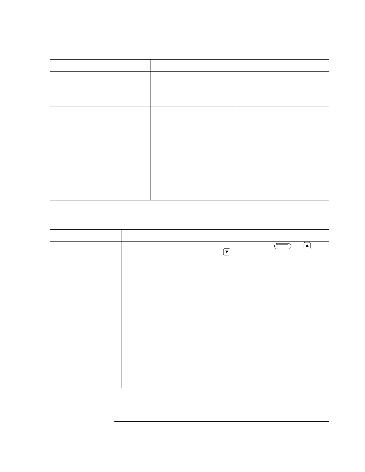
Troubleshooting Tables
Table 4-5 Printer
Symptom Possible Cause Corrective Action
Printed data are garbled. A printer cable is not fully seated.
Defective printhead.
Defective component in data path.
Poor print quality or some dots not printing. Dirty printhead.
Loose ESD brush fibers.
Incorrect printh ead or sensor cable
routing.
Defective printhea d or printhead
cables.
Defective component in printer circuitry.
Some dots always on. Defective printhea d.
Defective printhea d or printhead
cables.
Reseat connector J3 04.
Replace printhea d as sembly.
1.Replace printhead control cable.
2. Replace CPU assembly.
Clean printhead.
Remove loose brush fi bers and clean
printhead.
Make sure ther e is slack in the print head
cables.
Replace printhead assembly or printhead
cables.
Replace CPU assembly.
Replace printhea d as sembly.
Replace printhead assembly or printhead
cables.
Table 4-6 Keyboard and Display (LCD)
Symptom Possible Cause Corrective Action
Display stays blank or all
black. (M1770A / M1771A
only)
Contrast misadjusted.
Keyboard cable i s not fully seated.
No power being su pplied to keyboard assem-
bly.
Defective keyboar d as sembly.
Defective LCD assembly
Defective contrast control in CPU assembly.
Adjust contrast using the and . or
keys.
Reseat keyboard cable.
Test power suppl y. Replace if de fective.
Replace keyboard assembly.
Replace LCD assembly .
Replace CPU assembly.
Shift
Keys won’t work. Unable to
enter data or oper ate controls.
Garbled data on display. Keyboard cabl e not seated correctl y.
Keyboard cable unpl ugged.
Keyboard circuit board defective.
CPU assembly defective.
Keyboard flex cable connection is p oor.
Defective LCD.
Defective keyboar d as sembly.
Defective CPU assembly.
Reconnect keyboard cable.
Replace keyboard assembly.
Replace CPU assembly.
Make sure cable from keyboard to CP U assembly is properly seat ed.
Make sure fle x cable is fully inserted and locked
in each connector.
Replace LCD assembly .
Replace keyboard assembly.
Replace CPU assembly.
4-11
Page 80

Troubleshooting Tables
Table 4-7 Storage (Option #A05 0nly)
Message Possibl e Cause Possible So lutions
ECG too noisy to sto r e
(This message appears briefly on th e
screen)
"Storage system full" messag e appears
when fewer than 30 ECGs are stored.
Unable to store ECG
(This message appears briefly on th e
screen)
Unable to retrieve ECG
(This message appears briefly on th e
screen)
Poor electro de contact. Dry or dirty electrodes.
Patient moving or not relaxed.
Lead wires may be picking up interference from poo rly grounded equipment
near the patient.
Patient cable is too close to the cardiograph or other power cor ds.
30 ECGs stored in memory.
Storage memory gradually wears out
after many thousand store/erase cycles.
Consequently, ECG storage capacity
decreases gradually over the life of th e
product.
A fault exists in the storage hardware. Call HP service
A fault exists in the storage hardware. Call HP service
Use new electrodes. Abrade skin. Reapply electrodes. Check expiration date on
disposable elec tr odes.
Reassure and relax the patient. Press the
Filter
fact.
Route lead wires al ong limbs and away
from other electrical equipment. Fix or
move poorly grounded equipment.
Move the cardiogr aph away from the
patient. Unplug the cardiograph and operate on battery power. Move other elec tr i cal equipment away from patient. Unplug
electric bed.
Delete some ECGs.
If under warranty, call HP serv ice. Gen er-
ally, stored ECGs are retrievable. If
remaining ECG storage cap acity is unacceptable, call HP service.
key if it is configured for Arti-
4-12
Page 81

Troubleshooting Tables
Table 4-8 Transmission (Option #A05 only)
Message Possibl e Cause Possible So lutions
Telephone busy, waiting to redial Busy telephone ay re mote site. Normal event. The cardiograph will
redial, waiting 30 seconds between
attempts, until the line is o pen or until th e
operator stops the transmission.
No answer, re-dialing Remote mo de m not c on n ected, or the car-
diograph modem is set to wait for an
answer for too few rings
Check telephone cable No dial tone. Check the telephone cable connection to
Check modem and cable No power to modem, or poor modem
cable connection.
Defective cable.
Defective modem.
Check cable Poor cable connection between cardio-
graph and TraceMas t er system.
Defective cable.
Check modem configuration Incompatible or improperly initialized
modem
Be sure the remote si te is read y to r eceive
the transmission. If necessary, extend the
time the modem will wait for a connec-
tion by adding the string “S7=90” to the
modem initialization string.
the modem. Attach the telephone cable to
a telephone to veri f y a dial tone on the
line.
Check that the data cable is attached to
the modem and to the cardiograph’s RS232 port. Check oper at i on of the RS-232
port.
Replace the data cabl e.
Run the modem self-test. Replace modem
if defective.
Check that the data cable is attached to
the cardiograph’s RS-232 port. Check
operation of the RS-2 32 port.
Replace the data cabl e.
Check the modem initializa tio n string for
legal modem commands. See you modem
documentation for legal commands for
your modem.
4-13
Page 82

Troubleshooting Tables
Table 4-8 Transmission (Option #A05 only)
Message Possibl e Cause Possible So lutions
No modem at remote site The l ocal modem could not complete the
connection. The mos t likely causes are:
1. Telephone cable disconnected from
local mo d em.
2. Remote modem turned off or disconnected from telephone line.
3. Telephone prematurely disconnected at
remote site.
4. Excessive noise on the telephone line.
5. Incompatible transmission protocols on
remote and local modems.
6. Incompatible modem setup strings on
the remote and local modems.
7. The remote modem did not answer the
phone cal within the time specified in
the modem’s S7 re gi ster, and the @
symbol is not present in the telephon e
number string in the cardiograph telephone directory.
1. Check all cable connections.
2. Be sure the remote mo dem is tu rned on
and connected to the telephone cable.
3. Retry the transmission.
4. Retry the transmission.
5. Check the cardiograph telephone directory and verify telephone number,
device type, and transmission speed.
6. Check the modem initialization string
commands that allow compatibility
with the remote modem.
7. Be sure the remote site is ready to
receive the transmission . Consid er
extending the time th e modem waits
for a connection by adding the string
“S7=90” to the modem initialization
string.
Transmission stopped unexpectedly. X of
N ECGs received.
Cable/ modem problem, Press any key to
continue.
Transmission stopped unexpectedly. X of
N ECGs received.
Modem was disconnected. Press any key
to continue.
Transmission stopped unexpectedly. X of
N ECGs sent. Remote site stopped communication (nnnn). Press any key to continue.
or
Transmission stopped unexpectedly. X of
N ECGs received. Remote site stopped
communication (nnnn). Press any key to
continue.
No power to modem, or p oor modem
cable connection.
Problem with telephone line or remote
modem.
Communication speed of the re mote
device does not match that of the cardiograph, or the remote site modem malfu nctions. The (nnnn) is the event code
associated with t he message, and is
recorded in the event log when this message appears. These events relate to the
transmiss ion prot ocol . See Tab le 4-9 for a
list of event codes.
Check that at least on of the modem’s
LEDs is on. Check that the data cable is
attached to the modem and to the cardiograph’s RS-232 po rt . Check operation of
the RS-232 port.
Check that at least on of the modem’s
LEDs is on. Check that the data cable is
attached to the modem and to the cardiograph’s RS-232 po rt . Check operation of
the RS-232 port.
Be sure the remote si te is read y to r eceive
the transmission.
Retry the transmission at 2400 bps.
Be sure the remote si te is read y to r eceive
the transmission.
Be sure the remote si te is ready to send
the transmission.
4-14
Page 83

Troubleshooting Tables
In addition to the error codes listed above, the following event codes are displayed on the
extended self-test report for cardiographs equipped with Option #A05.
Table 4-9 Event Codes (Option #A05 only)
Event # Definition Corrective Action
1223 PageWrite r X Li record corrupt ed during transmis-
sion. This code is fol l owed by an sub-erro r code.
3573 1. The battery was removed when the car di ograph
was not plugged in to AC power.
2. The battery fuse is defective.
3575 The cardiograph turned off due to ina ctivity. Normal event. No action required.
3577 The cardiograph turned off due to low battery. Plug cardiograph into AC power.
3700 The power wa s cycled quickly. Normal event. No action requ ired.
3701 Errors were detected in the front end communicat ion
link.
5160, sub code 3 No modem at remote si te. 1. Che ck all cable connections.
Retry the transmission.
Replace the battery.
Run the extended self-test to check operation of the
front-end.
2. Be sure the remote modem is turned on and connected to the telephone cable.
3. Check the cardiogr aph telephone director y and
verify telephon e number, device typ e, and transmission speed.
4. Check the modem initialization string commands
that allow compatibility with the remote modem.
5. Be sure the remote site is ready to receive the
transmission. Consider extending the time the
modem waits for a connection by adding t h e
string “S7=90” to the modem initialization string.
6. Retry the transmission
5160, sub code 4 Check modem configuration. Check the modem initialization string for legal
modem commands. See your mo dem documentati on
for legal commands for your modem.
5160, sub code 5 Check telephone cable. Check the telephone cable connection to the
modem. Attach the telephone c able to a telep hone to
verify a dial tone o n t he l ine.
5160, sub code 6 Tel ephone busy, wait in g to redial...
(after 30 secon d s, this message appears:)
Telephone busy, redialing...
5160, sub code 7 No answer, waiting to r edi al...
(after 30 secon d s, this message appears:)
No answer, redialing...
Normal event. The car di ograph will redial, wa iti ng
30 seconds between attempts, until the line is open
or until the operator stop s the transmission.
Be sure the remote si te is ready to receive a transmission. If necessary, extend the time the modem
will wait for a conn ection by adding the string
“S7=90” to the modem initialization string.
4-15
Page 84

Troubleshooting Tables
Event # Definition Corrective Action
5160, sub codes 10
and 11
5161 Transmissi on s to pped unexpectedly.
5162 Transmissi on s to pped unexpectedly.
5163 Transmissi on s to pped unexpectedly.
Check cable. (This message appea rs when the transmission type is Direct or Direct SCP)
Check modem and cable. (This message appears
when the transmission type is Modem or Modem
SCP.)
x of n ECGs sent
Cable/modem problem
Press any key to cont inue
or
Transmission stopp ed unexpectedly.
x of n ECGs received
Cable/modem problem
Press any key to cont inue
x of n ECGs received
Modem was disconnected
Press any key to cont inue
x of n ECGs sent
Remote site stopped communication
Press any key to cont inue
or
Transmission stopp ed unexpectedly.
x of n ECGs sent
Remote site stopped communication
Press any key to cont inue
Check that at least one of the modem’s LEDs is on.
Check that the data cable is attached to the modem
and to the cardiogr aph’s RS-232 port. Check operation of the RS-232 port.
Check that at least one of the modem’s LEDs is on.
Check that the data cable is attached to the modem
and to the cardiogr aph’s RS-232 port. w hen transmitting or receiving ECGs. Check operatio n of the
RS-232 port.
1. Check that at least one of the modem’s LEDs is
on. Check that the data cable is attached to the
modem and to the ca rdiograph’s RS-2 32 port
when transmitting or receiving ECGs. Check
operation of the RS-2 32 port.
2. Retry transmission at 2400 bps.
Be sure the remote si te is ready to send or re c eive
the transmission.
7127-7141 Fax transmission problems. 1. Verify t hat the remote fax is a gr oup III fax
machine.
2. Check the fax machine initialization string.
9001-9007 Sender time-out whil e w aiting for response fro m
receiver during transmission using D irect transmis-
sion protocol.
9010-9015 Receiver time-out waiting for response from sender. Retry transmission at 2400 bps.
9021 Normal Direct transmission link termination. No action. Normal event. Transmission completed
9022 Operator stopped transmission at remote site. Contact the remote site.
9023 Cardiograph stopped transmission due to a system
error at the local or remote site. The most common
remote site error is missing paper on the receiving
cardiograph.
Retry transmission at 2400 bps.
successfully
Check the receiving device to make sure it is read y
to receiv e the transm ission.
4-16
Page 85

Troubleshooting Tables
Event # Definition Corrective Action
9030-9035, 90429045, 9050, 9051,
9069-9085
9038 A non-speci fic error occurred d uring transmissio n. Retry transmissio n at 2400 bps.
9046 Remote device not supported. Verify that the remote site is compatible with the
9047-9049 Requested an ECG from an unrecognized device. Verify that the remote site is a TraceMaster ECG
9052-9065 Premature quit command received from remote site. Contact remote site.
9066 Defective FLASH memory 1. Perform the extended self-test (refer to Chapter
9067 Memory all ocation fault during transmission . 1. Turn off, wait 30 seconds, turn on.
9086 Unrecognized device for transmission Verify that the remote site is compatible with the
9087-9089 Printer problem during transmission. 1. Check the paper supply.
Direct transmi ssion protocol error. Retry transmi ssion.
PageWriter cardiograph.
Management System.
2).
2. If the extended self-test fails, repl ace the Option
#A05 PCA.
2. Retry transmission.
PageWriter cardiograph.
2. Be sure the printer door is closed.
3. Retry the transmission.
9163 Transmission stopped unexpectedly.
x of n ECGs sent
Remote site stopped communication
Press any key to cont inue
or
Transmission stopp ed unexpectedly.
x of n ECGs received
Remote site stopped communication
Press any key to cont inue
9200 An ECG was requested from a FAX machine. Select a connection type of Modem, Direct, Modem-
9500-9674 Unable to build an SCP rec or d for transmission. Turn off, wait 30 seconds, turn on. Retry the trans-
9575-9895 SCP transmission errors. Retry the transmission. Call HP if the error persists.
9585, 9586 The ECG tra nsmission stalled bef or e completion,
either because th e fi l e transfer protocol is absent or
is in an unexpected state, or another communication
error occurred.
9640, 9769 The receiving device rejected a transmitted ECG
because of data errors.
1. Verify the transmission speed matches that of the
remote site.
2. Verify the remote system communication is operating correctly
SCP, or DirectSCP to r equest an ECG from a r emote
site.
mission. If the error persists, call HP.
Wait one minute, then retry the transmission. Check
or restart the communic ation software at the remote
site. If the error persists, call HP.
Wait one minute, then retry the transmission. If the
error persists, call HP.
4-17
Page 86

Troubleshooting Tables
Table 4-10 Recorder Problems
Problem Corrective Action
Is the cardiograp h turned on? The LCD screen shoul d be on. Use the shift and
up/down key to increa se/decrease intensity.
Is the AC power ligh t on? If the cardiograph is plugged in and the AC lig ht is
not on, check fuses.
Is the battery adequately charged? The low battery message (in the upper-left corner of
the screen) will a ppear if the battery is no t charged.
Is the cardiograph out of paper or is paper
jammed?
Is the paper sensor lens dirty or obstructed? Clean sensor lens.
Is the paper door com pletely closed? Open pape r door slightly and clos e i t. Li st en for the
Is there an error message? The error messages that display on the screen will
The cardiograph will not record an ECG unless
paper is loaded and no jam exists.
door safety latch to lock.
instruct y ou as to wha t action to take. If it is something that you can correct, the message will instruct
you as to what to do. If an error number displays,
perform the fol lowing steps:
1. Turn the cardiograph to STANDBY from the
front panel.
2. Wait 20 seconds or more and turn the unit on
again.
3. Press AUTO or MANUAL. If the cardiograph
turns itself to STANDBY, the battery is not
operating properly.
4. If error persists, call HP Medical Call Center
1 800 548-8833
4-18
Page 87

Testing the Power Supply
WARNING
CAUTION
NOTE
4Testing the Power Supply
Use this procedure to check the voltages produced by the power supply. The cardiograph
must be connected to AC power to test all the power supply voltages. All th e voltage
measurements are taken with respect to ground, unless indicated. Refer to Figure 4-2 for
voltage test point locations.
When the cardiograph is connected to AC power, there are dangerous voltages
present in the areas indicated in Figure 4-2 and on the Capacitor Assembly. Do
not touch any exposed metal while the cardiograph is open and AC power is
connected.
1. Open the top cover assembly as described in Chapter 5.
2. Without replacing the top cover, plug the keyboard cable into J201.
3. With the battery removed, plug the unit into AC po wer.
Be very careful to not short any signal to ground or to other pins. This will result in
cardiograph failure.
4. Verify AC LED is lit. If it is not lit, measure ACON between ground and the back-
plane pin 5 of J3. It should read approximately 5 Vdc. The presence of this voltage
confirms the proper operation of the primary transformer, fuses and ACON regulator
circuit.
5. Measure VSEC between the anode of CR1 (-VSEC) and the cathode of CR8
(+VSEC). It should read approximately 25 Vdc. The presence of this voltage confirms the proper operation of the mains transformer/primary power circuit and the
secondary rectifier filter.
6. Measure VBAT between ground and the point marked VBAT. It should read approx-
imately 6.7 (minimum) to 7.03 (maximum) Vdc @ 25° C. This voltage confirms the
proper operation of the battery charger.
The voltage range for environments with temperatures other than 25° C can be calculated
from the following equati ons :
-3
Vmin = [2.220 - (T - 25)3.9×10
]3.016, where T = temperature in °C
Vmax = [2.315 - (T - 25)3.9×10⁻³]3.024
7. Measure UNSW+5V between ground and the point marked UNSW+5V. It should
read 5 Vdc. Its presence confirms the proper operation of the unswitched 5 volt regulator.
4-19
Page 88

Testing the Power Supply
8. Turn the cardiograph On by pressing .
2Q6WDQGE\
9. Measure SW+5V between ground and the point marked SW+5V. It should read +5
Vdc. Its presence confirms the proper operation of the switched 5 volt regulator and
boost regulator.
10. Turn the cardiograph to Standby.
11. Unplug the cardiograph from AC power.
12. Look on the first page of the Extended Self-test pri ntout and verify that the printhead
voltage is approximately 26.1 Vdc. If the voltage is correct then the power supply test
is complete and the cardiograph may be reassembled. If the voltage is incorrect or the
printer is inoperative then proceed with the following steps.
13. Disconnect the keyboard connector from J201. Place the upper case on top of the bot-
tom case assembly. Turn the unit bottom-side up.
14. Install the battery and turn the unit top-side up.
15. Remove the upper case.
16. Connect the keyboard cable to J201.
17. Turn the cardiograph On.
18. Connect one end of a jumper wire with grabber clips to pin 1 of VR5. The jumper
wire is now connected to +5V. Connect the other end to the lead of R37. The other
end is now connected to PPWRON.
19. Measure VPRINT between ground and the point marked VPRINT. It should read
approximately 26.1 V DC. Its presence confirms the proper operation of the printing
supply circuit.
20. Remove the jumper wire.
21. Turn the cardiograph to Standby.
22. Close the top cover assembly.
4-20
Page 89

Testing the Power Supply
Figure 4-2 Voltage Test Locations
4-21
Page 90

Testing the Power Supply
4-22
Page 91

Removal and Replacement
NOTE
4Introduction
This chapter contains procedures for removing and replacing these cardiograph
subassemblies:
• battery
• keyboard and the keyboard display assembly
• top cover assembly
• printer drive assembly
• printhead assembly
• CPU assembly
• power supply assembly
• internal cabling
• #A05 storage and transmission assembly
The way in which wires and cables are routed and dressed inside the main chassis plays an
important part in reducing electromagnetic and radio frequency interference emitted by
the cardiograph. When you disassemble any part of the cardiograph, pay special attention
to the way cables and wires are routed and dressed. When you reassemble the cardiograph ,
be sure to route and dress all cables and wires as they were originally.
Tool Requirements
These are the tools you need to remove and replace the cardiograph’s subassemblies:
• 7-mm or 9/ 32-inch wrench
• 7/32-inch wrench
• 2 flat-bladed screwdrivers
• #0 Phillips screwdriver
• T-10 Torx drivers (or Torx driver kit, HP part number 5181-1933)
• Long-nose pliers (recommended, but not necessary)
• IC Extraction Tool (AMP 821591-1 size 44)
5-1
Page 92

The Battery
NOTE
WARNING
NOTE
The directions in this chapter gener ally assume you are facing the front of the cardiogr aph
as you work. Thus, for example, the “left side of the cardiograph” mean s “your left side as
you face the front of the unit.”
4The Battery
This section explains how to remove and replace the battery. These procedures app ly to all
units.
Removing the Battery
To remove the battery:
1. Turn the cardiograph to Standby.
2. Unplug the cardiograph from AC power.
3. Turn the cardiograph botto m-side up.
4. Slide the battery door in the direction of the arrow until it unlatches (approxim a tely
1/2 inch), as shown in Figure 5-1. Lift off the door.
5. Unplug the battery connector from the cardiograph by squeezing the locking tabs of
the connector and pulling it straight out from the cardiograph.
6. Remove the battery.
To replace the battery, perform the procedure Removing the Battery in reverse.
Dispose of or recycle depleted batteries according to local regulations. Do not
disassemble, puncture, or incinerate the battery assembly.
To insure full battery capacity, connect the cardiograph to AC power and charge the
battery for 16 hours with the cardiograph in Standby mode.
5-2
Page 93

The Battery
Figure 5-1 Removing the Battery Door.
A Battery door
5-3
Page 94

The Keyboard Assembly
CAUTION
5The Keyboard Assembly
This section explains how to remove and replace the keyboard assembly. The keyboard
procedures apply to all models. The keyboard display procedures only apply to
PageWriter 200/200i/300pi.
Note that replacement part numbers for key board assembly comp onents vary with the unit
serial number. Refer to the Part List section of this manual to verify replacement part
numbers.
Removing the Keyboard
The keyboard assembly consists of the keyboard overlay, the keyboard assembly, the
flexible circuit, and the keyboard display.
Removing the Keyboard Assembly
Use an electrostatic wrist band or other approved method for protection against
electrostatic discharge when handling the keyboard assembly.
To remove the keyboard assembly:
1. Perform the procedure Removing the Battery.
2. Turn the cardiograph top-side up.
3. Carefully insert a flat-bladed screwdriver into the notches at the front edge of the key-
board overlay and pry the front edge of the key boar d ov erla y up. Refer to F igure 5-2.
4. Repeat with the rear notches of the keyboard overlay and remove the overlay.
5-4
Page 95

The Keyboard Assembly
Figure 5-2 Removing the Keyboard Overlay
A. Overlay notches
5. Using two screwdrivers, place the blade of one screwdriver on the leftmost latch of
the keyboard assembly and push toward the rear of the cardiograph. See Figure 5-3.
Carefully insert the blade of the second screwdriver in a notch to the right or left of
the latch and lift up on the keyboard assembly. The leftmost latch should unlatch.
Repeat with the center and rightmost latches.
Figure 5-3 Removing the Keyboard.
A. Notches
B. Latches
5-5
Page 96

The Keyboard Assembly
CAUTION
6. Carefully lift the assembly and tilt it until the keyboard and control board are accessi-
ble.
7. Disconnect the keyboard ribbon cable from J201 on the control board.
8. Disconnect the green wire from the keyboard.
9. Remove the keyboard.
Do not remove the keyboard circuit board from the keyboard bezel. Removing the board
can impair the long-term reliability of the cardiograph.
Removing the Keyboard Flexible Circuit
To remove the keyboard flexible circuit:
1. Perform the procedures Removing the Battery and Removing the K eybo ard Assembly.
2. Place the keyboard assembly with the keys down on a flat surface.
3. Grasp the tabs at the ends of one of the con nectors and gently pull toward the flexible
circuit. The locking sleeve should now be extended.
4. Repeat with the other connector.
5. Remove the keyboard flexible circuit.
To replace the keyboard flexible circuit, perform the above procedure in reverse.
Removing the Keyboard Display
The keyboard display consists of the LCD, display shield, and mounting hardware.
1. Perform the procedure Removing the Keyboard Assembly.
2. Using a #0 Phillips screwdriver, remove the 4 screws that secure the LCD display.
3. Remove the display shield and 4 rubber o-rings.
4. To remove the flexible circuit, grasp the tabs at the ends of one of the connectors and
gently pull toward the flexible circuit. The locking sleeve should now be extended.
Repeat with the other connector. Lift the flexible circuit out.
5. Remove the LCD.
To replace the keyboard display, perform the above procedure in reverse.
5-6
Page 97

The Keyboard Assembly
CAUTION
Replacing the Keyboard
To replace the keyboard, perform the following steps:
1. Connect the green wire to the spade connector on the keyboard.
2. Connect the keyboard ribbon cable to J201 on the control board.
3. Position the top of the keyboard so the four tabs on the top of the keyboard frame are
placed under t he lip on keyboard well.
4. Press down on the base of the keyboard until each latch is latched.
The rubber keypad and/or keyboard assembly may be damaged if any key or LED
becomes trapped under the overlay while replacing the overlay. Make sure each and ever y
key and LED comes through its hole in the overlay.
5. Align the overlay with each of the keyboard keys and LEDs. Position your thumbs
along the front edge of the overlay near each end. Apply pressure on the overlay
toward the rear of the unit and then press down on the ov erlay. Th is is on e continuous
motion. The front of the overlay should now be snapped into place. Snap the rear of
the overlay into place.
5-7
Page 98
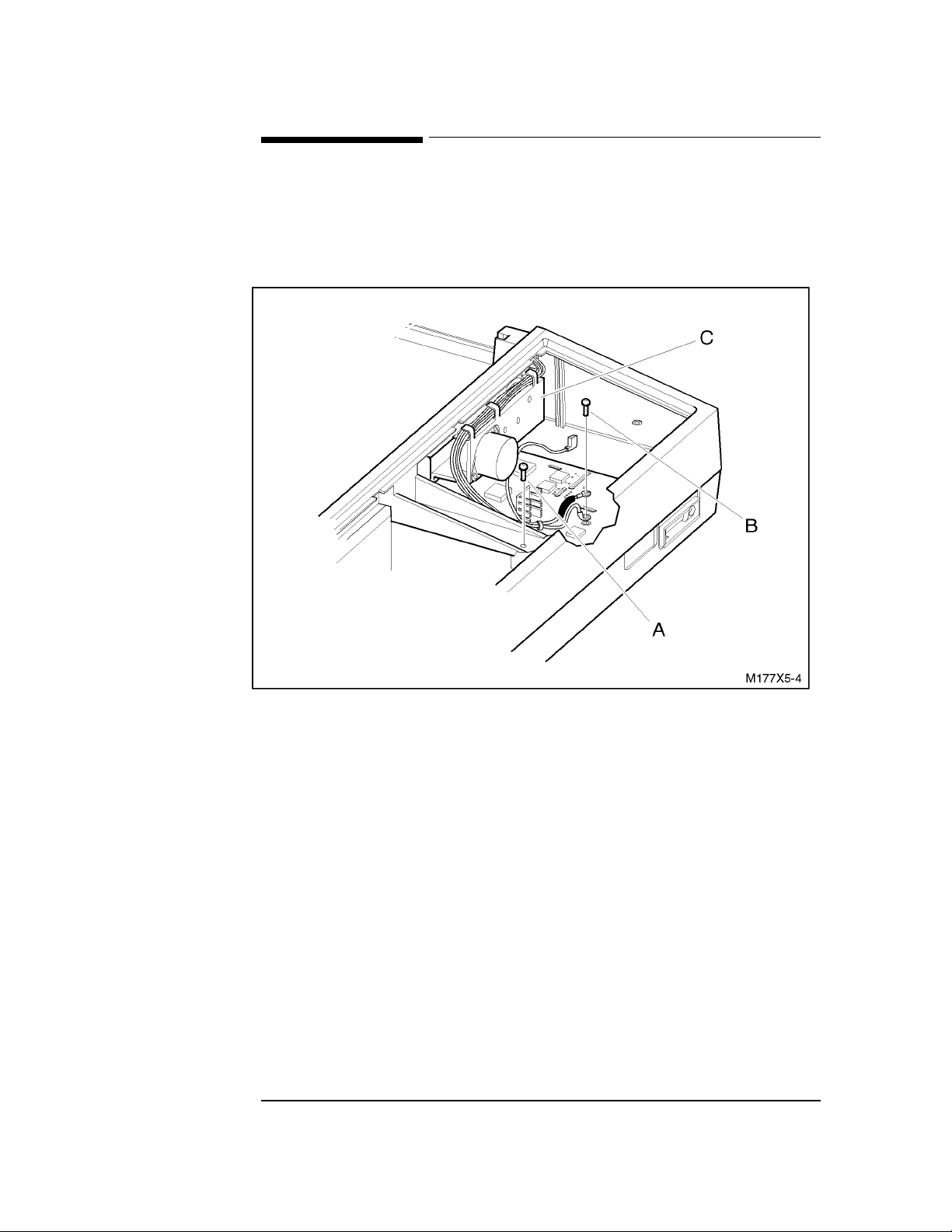
The Top Cover Assembly
5The Top Cover Assembly
This section describes how to remove and replace the top cover assembly. The top cover
assembly includes the upper chassis, the printer door, and the printer assembly.
Figure 5-4 Interior Details of Top Cover Removal
A. Chassis screw
B. Control board screw
C. Printer drive assembly
Opening and Removing the Top Cover Assembly
To open the top cover assembly:
1. Perform the procedures Removing the Battery and Removing the K eybo ard Assembly.
2. Turn the cardiograph bo ttom-side up.
3. Using a Torx T -10 screwdriver, remove the five screws that sec ure the upper a nd
lower parts of the chassis.
4. Turn the chassis upright. This will cause the five screws to fall out of the chassis. Per-
form this step slowly to avoid losing the s c rews .
5. Using a Torx T-10 screwdriver, remove the chassis screw seen through the keyboard
opening. Refer to Figure 5-4.
5-8
Page 99

The Top Cover Assembly
WARNING
NOTE
NOTE
The capacitors on the connection assembly next to the control board store
hazardous amounts of energy during AC and battery operation. Be careful not to
touch any of the exposed capacitor connections.
6. Disconnect control board connector J303 by grasping all the wires of the connector
and gently pulling straight up. Repeat with connectors J304, J306, and capacitor
board connector J4.
7. Using a Torx T-10 screwdriver, remove the screw that secures the 2 g reen wires to the
control board, as shown in Figure 5-4.
8. Lift the top cover off of the chassis.
Replacing the Top Cover Assembly
To replace the top cover assembly, perform the above procedure in reverse order.
Place the long side of the foam block in between the side of the top case and the side of the
printhead well to keep the printhead wiring in place.
When securing the 2 green ground wires to the control board, make sure the lugs on the
ground wires point toward the battery compartment.
5-9
Page 100

The Printer Door Assembly
5The Printer Door Assembly
This section describes how to remove and replace the printer door assembly.
Figure 5-5 Removing the Printer Door Retainer Clip
A. Retainer clip
Removing the Printer Door Assembly
To remove the printer door assembly:
1. Release the door latch and slide the printer door out to the first stop.
2. Compress and remove the plastic retainer clip visible at the end of the front guide rai l,
as shown in Figure 5-5.
3. Slide the door out of the rails.
5-10
 Loading...