

Page 1
HP
Viridia
M1165/66/67/75/76/77A
Component
System
HP
M1205A
and
Monitorinc
Viridia
26/24
Ser
ΠΠ
M1046-9001K
User’s
Volume
System
Reference
1
Information
Ca
Part
Printed
First
HEWLETT®
PACKARD
Number
02/99
Edition
M1046-9001K
Manual
Page 2
Notice
This
document
Reserved.
prohibited,
Hewlett-Packard
3000
Andover,
(978)
Reproduction,
except
Minuteman
MA
687-1501
01810-1085
contains
as
allowed
Road
proprietary
adaptation,
under
information
or
translation
the
copyright
which
without
laws.
is
protected
prior
by
copyrigt
written
permis
Publication
number
M1046-9001K
Warranty
The
information
Hewlett-Packard
not
limited
Hewlett-Packard
consequential
material.
Copyright © Hewlett-Packard
to,
the
damages
contained
makes
no
implied
shall
not
in
warranties
be
connection
in
this
document
warranty
liable
Company,
is
of
any
kind
or
merchantability
for
errors
with
the
1999
subject
with
to
regard
contained
furnishing,
change
and
herein
without
to
this
fitness
or
performance,
notice
material,
for a partic
for
incidental
or
use
in
«
Page 3
Printing
New
editions
Update
pages
rearranged
The
documentation
date
changes
incorporated
when
extensive
packages
to
be
merged
due
History
of
this
document
may
be
by a revision
to
changes
printing
when a new
at
reprint
technical
will
issued
between
on a previous
date
edition
do
not
cause
changes
incorporate
editions
date
at
the
page
and
part
is
printed.
the
date
are
incorporated.
number
PFistEditon................................
Important
United
The
EN
Device
States
federal law
M1165/66/75/76A
60601-1-2
and
Directive
carries
(MDD).
restricts
Systems
C€o363
these
comply
Marking
devices
with
all
bottom
are
(Minor
to
change.)
February
to
UL544,
to
Council
material
and
contain
of
the
page.
not
considered
indicate
corrections
The
1999
sale
by
CSA
22.2-125,
Directive
updated
replacement
Note
its
current
and
document
or
on
the
TEC
93/42/EEC,
since
that
revised.
edition.
updates
part
order
601-1,
the
and
page
wi
of
ЕК
Eu
p
*
ni
a
The
M1167/77A
EN
60601-1,
European
The
M1205A
EN60601-1,
European
The
M1205A
_ ; through
and
Medical
option
and
Medical
option
5,
and
Systems
EN
60601-1-2
Device
020
and
EN60601-1-2
Device
021
complies
VDE
0871
comply
and
Directive
022
and
Directive
level
A.
with
UL2601-1,
carries
(MDD).
complies
carries
(MDD).
with
UL2601,
CSA
《CE&o3s66
with
UL2601,
C€o123
IEC
22.2
Marking
IEC
Marking
601-1,
No.
601.1-M90,
to
601-1,
to
Council
CSA
Council
CSA
C22.2
TEC
Directi
C22.2
Directiv
no.
601-1,
6
n
Page 4
Electromagnetic
The
electromagnetic
performed
Manufacturer’s
EMC
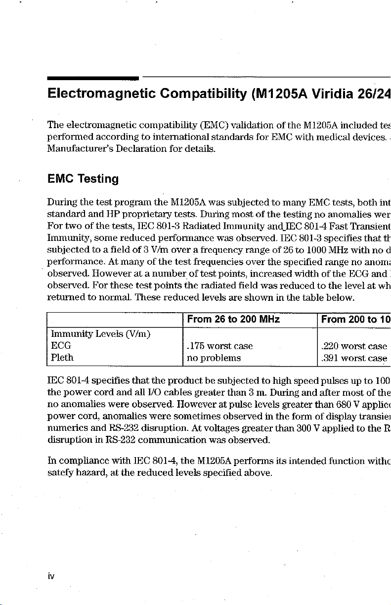
During
standard
For
two
Immunity,
subjected
performance.
|
observed.
observed.
returned
Immunity
ECG
Pleth
IEC
the
power
no
anomalies
power
numerics
disruption
Testing
the
and
of
some
to a field
However
For
to
Levels
801-4
specifies
cord
cord,
and
in
according
Declaration
test
program
HP
proprietary
the
tests,
reduced
At
many
these
normal.
(V/m)
and
were
anomalies
RS-232
RS-232
Compatibility
compatibility
to
international
for
details.
the
M1205A
tests.
IEC
801-3
Radiated
performance
of 3 V/m
at a number
test
These
over a frequency
of
the
test
points
the
reduced
that
the
product
all
I/O
cables
observed.
disruption.
communication
were
However
sometimes
(EMC)
standards
was
During
Immunity
was observed.
frequencies
of
test
points,
radiated
levels
From
26
„175
worst
no
problems
be
subjected
greater
at
observed
At
voltages
was
(M1205A
validation
for
subjected
most
of
range
over
increased
field
was
are
shown
to
200
MHz
case
to
than 3 m.
pulse
levels
in
greater
observed.
of
EMC
to
many
the
testing
and
IEC
IEC
of
26
the
specified
reduced
in
high
During
greater
the
than
Viridia
the
M1205A
with
medical
EMC
no
anomalies
801-4
Fast
801-3
specifies
to
1000
MHz
range
width
of
to
the
the
table
below.
From
.220
.391
speed
pulses
and
after
than
form
of
display
300 V applied
26/24
included
tests,
the
ECG
level
200
worst
worst
most
680 V appliec
tes
devices.
both
int
wer
Transient
that
with
no
no
anom:
and
at
wh
to
10
case
case
up
to
100
of
the
transier
to
the
|
th
d
|
R
In
compliance
satefy
hazard,
with
at
the
IEC
801-4,
reduced
the
M1205A
levels
performs
specified
above.
its
intended
function
withc
Page 5
System
The
%
patient
|
amplifiers
monitors
problem
Characteristics
phenomena
monitors
already
in
used
actual
discussed
in
to
in
use
today.
display
use by
use.
above
are
This
performance
the
physiological
customers,
not
unique
signals.
interference
to
is
the
M1205A
due
to
the
Among
from
electromagnetic
but
are
very sensitive
the
many
similarly
charact
hig
|
sourc
Avoiding
When
electromagnetic
can
be
taken
Eliminate
reduce
Attenuate
may
power
Reduce
to
maximum
required.
often
Add
devices
Customer
Electromagnetic
interference
to
mitigate
the
their
the
be
reduced
cord,
the
sensitivity
By
be
eliminated.
external attenuators.
such
Engineer
the
problem.
source.
strength.
coupling.
plugging
sensitivity.
reducing
as
by
moving
an
isolation
can
Possible
the
of
the
If
For
be
Interference
(EMD
is
sources
the
coupling
and/or
M1205A
the
gain
If
of
rearranging
into a different
system.
the
EMI
transformer
help
ECG
of
the
becomes
in
In
system
determining
encountered
of
EMI
can
path
is
through
the
all
of
the
amplifier
the
receiving
an
unusually
or a transient
there
be
turned
leads.
circuit
EMC
testing
gain
the
the
need
are a number
off
or
the
patient
If
the
coupling
may
help.
the
was
four
EMI,
the
difficult
suppressor
for
external
problem
mover
leads,
M1205/
times
interf
may
o
t
i:
w
be
d
Page 6
Intended
Use
Intended
Use
Description
The
HP
M1165/66/67/75/76/77A
Viridia
The
battery
HP
26/24
M1205A
power.
Series
Viridia
Monitors
Purpose
The
HP
M1165/66/67/75/76/77A
Viridia
generates
M1165/66/67/75/76/77A
24
Patient
The
Viridia
26/24
Series
Series
alarms
Monitors
and
Population
HP
M1165/66/67/75/76/77A
26/24
Series
measures
are
is
Viridia
are
Models
recordings.
Viridia
not
intended
24CT
Viridia
and
Component
therapeutic
Viridia
to
Component
network
and
Component
displays
It
exchanges
devices.
Component
be
used
Monitoring
connectable
26
CT
may
Monitoring
multiple
Monitoring
on
physiological
information
Monitoring
adult,
pediatric,
bedside
powered
System
System
patient
by
System
with
and
System
and
and
monitori
either
AC
and
parameters
compatible
the
HP
and
neonatal
the
line
the
an
dev
M120:
the
patie
E
E
E
Environment
The
HP
M1165/66/67/75/76/77A
Viridia
is
It
serial
The
Viridia
“United
vi
26/24
Series
not
intended
communicates
1/0
port.
HP
M1165/66/67/75/76/77A
26/24
Series
States
is
for
home
with
Monitors
Federal
intended
use.
devices
are
jaw
restricts
Viridia
to
such
Viridia
Component
be
used
as a central
Component
prescription
this
in a clinical
station
devices
device
to
sale
Monitoring
environment
through
Monitoring
and
will
by
or
System
network
System
carry
on
the
and
by
licensed
and
the
order
the
H
interfac
the
E
followi
of a pl
|
Page 7
Indications
Condition
The
HP
M1165/66/67/75/76/77A
Viridia
to
recordings
Part
The
Viridia
from
26/24
measure
of
Body
HP
M1165/66/67/75/76/77A
26/24
accessory
Frequency
The
HP
M1165/66/67/75/76/77A
Viridia
Physiological
The
Viridia
treatment,
-
66/67/75/76/77A
are
26/24
HP
M1165/66/67/75/76/77A
26/24
to
well
suited
Series
and
display
of
adult,
Series
electrode,
of
Series
Series
assess
Viridia
for
for
Use
Monitors
pediatric,
or
Type
does
Use
Monitors
Purpose
Monitors
adequacy
Component
patient
Viridia
are
multiple
or
of
Tissue
Viridia
not
contact
transducer,
Viridia
are
Viridia
are
of
monitoring.
Component
generally
physiological
neonatal
indicated
patients.
with
Component
the
body
and
sensor
Component
indicated
indicated
treatment,
Monitoring
for
Component
when
or
Monitoring
when
parameters
Which
or
use
to
System
the
Monitoring
tissue
of
devices.
Monitoring
when
Monitoring
the
purpose
rule
out
and
System
the
clinician
and
waves,
Device
System
the
patient.
System
prescribed
System
is
to
causes
the
of
HP
and
the
decides
to
gener:
Interac
and
the
Signals
and
the
by a clinici
and
the
gain
informe
symptoms.
M1205A
Vir
]
|
a
|
|
Patient
Adult,
pediatric,
Population
and
neonatal
non-ambulatory
patients.
Page 8

Indications
for
Use
Prescription
The
HP
M1165/66/67/75/76/77A
Viridia
26/24
Series
Versus
Monitors
Over-the-Counter
Viridia
are
Component
prescription
devices.
Monitoring
System
and
the
H
viii
Page 9
Warnings,
Warnings,
information
and
section
Warning
A
“warning”
procedures
*
«
e
+
cautions,
the
HP
M1205A
refer
For
continued
followed.
procedures.
Explosion
Alarms - Do
Adjustment
patient
combines
This
equipment
professionals.
Cautions,
and
about
the
Viridia
to
the
equipment
calls
attention
are
not
safe
Instructions
Hazard-
not
of
alarm
jeopardy.
close
notes
The
HP
26/24
followed.
use
in
Do
not
rely
exclusively
volume
Remember
personal
is
only
intended
and
Notes
are
used
throughout
M1165/66/67/75/76/77A
Series.
in
general.
to
of
this
this
use
surveillance
The
the
user
equipment,
manual
this
equipment
on
the
to a low
that
the
for
warnings
of
in
no
audible
level
most
with
use
in
imminent
it
way
or
reliable
healthcare
this
Viridia
and
is
necessary
supersede
in
the
alarm
off
during
correct
User’s
Manual
Component
cautions
hazard
that
presence
system
patient
method
operation
facilities
to
give
Monit
included
to
people
the
listed
established
of
flammab
for
patient
monitorů
of
patient mo:
of
monitorů
by
trained
y
ix
it
in
me
1
‧
The
ambulances.
+
This
®
To
reduce
qualified
‧
This
interference
possible.
product
product
the
personnel.
equipment
is
is
risk
on
not
not
may
the
intended
intended
of
for
for
electrical
interfere
ultrasound
outside
home
shock,
with
ultrasound
display.
hospital
use.
do
NOT
Try
to
use
remove
imaging
keep
the
such
as a helicopter:
any
cover.
equipment
instruments
Refer
by
cau
as
:
fa
Page 10
Indications
+
Exposure
dangerous.
supplies,
clean
with
department
*
Although
recommended
this
se
Connecting
powered
interface
permanent
sure
HP
Viridia
*
Do
not
of
the
disrupt
Caution
A
“caution”
user.
for
Use
of
electrical
Electrical
parameter
and
dry.
Thoroughly
liquids.
If
additional
or
Hewlett-Packard
this
equipment
to
equipment.
the
HP
on
is
not
lock-up
damage
the
SDN
interface
monitoring
connect a second
Viridia
calls
Model
Viridia
attention
module
contacts
contacts
module
decontamination
is
avoid
the
Viridia
monitoring
supported.
may
occur.
will
result.
cable
network
rack
24CT
or
communication.
to a condition
or
and
plug-in
dry
any
Response
shielded
use
of
electrically
Error
Power
To
prevent
is
properly
(SDN).
by a cable
26CT.
connections
to
connections
connections
electrical
connections
is
required
Center.
against
Electromagnetic
radiating
network
codes
cycling
and
the
(SDN)
HP
unintentional
secured
when
using a module
Using a second
or
possible
situation
saline
such
as
and
rack
Viridia
product
at
both
rack
or
other
cable
connections
that
please
contact
Interference
devices
cable
when
monitoring
will
recover
disruption
ends
connected
that
could
liquids
connectors,
mu
become
cor
yow
in
close
pr
the
pro:
neti
the
in
mor
when
conne
rack
docke
by a cz
cause.
a:
p
®
Ventilation
equipment
not
locate
*
Maintenance - Failure
employing
may
+
Do
not
the
internal
solutions
The
monitor
Requirements - Failure
failure
equipment
the
cause
undue
spray
components
should
and,
use
of
equipment
cleaning
be
should
in
turn,
in
an
on
the
this
equipment
solutions
and
applied
be
turned
jeopardize
enclosed
part
of
failure
directly
cause
to a cloth
off
during
to
meet
ventilation
the
functions
area
which
the
responsible
to
implement a satisfactory
and
possible
onto
the
equipment
and
malfunction
the
cloth
requirements
could
individual, hospital,
health
monitor.
used
cleaning.
of
automated
restrict
hazards.
Moisture
or
to
wipe
may
mor
heat
dissip:
maintene
drop]
failure.
the
mon
«
c
Cle:
Page 11

‧
Replacement
parts
degradation
components
and
accessories
Parts - It
of
performance.
are
listed
is
be
at
highly
used
the
recommended
with
this
Accessories
back
of
the
that
equipment.
and
parts
appropriate
only
Hewlett-Packard
Failure
for
to
individual
section
in
do
this
so
may
module
manu
1
Note—A
may
precede
At
this
time,
diagrams,
which
will
the
equipment
Support
note
gives
or
follow
Hewlett-Packard
component
assist
the
which
Offices
is
provided
special
the
part
user's
are
classified
instructions
applicable
will
lists,
text.
make
descriptions,
appropriate
by
Hewlett-Packard
at
the
end
of
to
highlight
available
calibration
qualified
this
manual.
an
operating
on
request,
instructions,
technical
to
procedure
and
in
English
or
personnel
be
repairable. A list
to
repair
or
on
other
{
{
«
Page 12
Indications
for
Use
Using
To
comprehensive
The
parameter
The
This
place
works,
* * Introducing
+
«
*
This
enable
you
User's
Reference
module
Core
section
for
new
and
the
HP
Getting
Configuring
Other
Document
of
shows
Patients
Manual
to
find
index
the
users
you
the
M1205A
Started
the
information
at
the
back.
Manual
guides.
guide
to
start
how
HP
Viridia
System
is
separated
contains
because
to
get
M1165/66/67/75/76/77A
26/24
easily,
there
all
the
general
it
gives
started.
Series
is a contents
into
two
information
an
introduction
Here
is a list
Viridia
parts;
of
Component
list
the
the
core
about
to
the
major
at
the
document
system
the
front
of
an
system.
and
sections:
Monitoring
th
|
tl
*
Alarm
‧
Recording
*
Trends
+
Installation
‧
Care
xii
Functions
Functions
and
Data
and
and
Cleaning
Management
Patient
Safety
Page 13
Parameter
These
sections
monitoring,
white
tab
which
Module
each
and
problem
has
Sections
contain
solving
the
title
information
if
you
of
the
section.
for
one
encounter
parameter
difficulty.
module.
Each
This
section
cover
is
sey
Note—
available
modules
information
Note—The
therefore
Although
functionality
the
The
Notice
77A
Viridia
HP
M1165/66/67/75/76/77A
Gas
Module
This
Manual
B.0
monitor
a.
b.
User’s
for
you
for
screenshots
differ
to
there
Component
the
the
The
the
system.
have
the
from
the
may
may
and
is
only
can
be
Release
suffix
suffix
Reference
ordered,
parameters
displayed
what
User
be
products
not
be
the
HP
applicable
identified
B.0
of
the
of
Manual
This
means,
the
screens
and
actually
in
Monitoring
the
same.
Viridia
M1205A
the
Viridia
for
by:
label on
EPROMpack
— © Monitor
EPROMpack
contains
of
will
functions
in
this
appears
your
System
This
Component
Release
the
monitor,
information
course,
manual
area
User’s
26/24
part
that
depending
not
always
is
valid
were
on
your
that
and
the
Reference
Series
B.0
versions
or
number.
Revision”: — ‘Show
part
number
apply
for
ail
generated
screen
look
similar
HP
M1205A
Monitoring
only.
of
To
on a Release
for
all
to
the
during
to
Manual
System,
the
monitors
view
the
parameter
on
the
your
system.
systems.
in
demo mode
patient
the
HP
Viridia
is
intended
this
number,
SW
Rev.
B.0
model
moni
M1165
26/24
the
M102
listed
Monito
ar
H
Se
tc
al
pre
Page 14
Responsibility
of
the
Manufacturer
Responsibility
Hewlett-Packard
performance
assembly
out by
the
electrical
the
instrument
To
ensure
conjunction
HP
M1026A
wherever
that
these
available.
parts
Manufacturer’s
For
South
America,
Hewlett-Packard
3000
Andover
MA
01810-1099
only
of
the
operations,
persons
optimum
with
the
Anesthetic
may
Minuteman
equipment
installation
If
of
the
Manufacturer
considers
itself
if:
extensions,
authorized
is
used
usage,
HP
M1165/66/67/75/76/77A
Gas
non-HP
cause
by
of
in
accordance
we
recommend
Module
parts
to
the
HP,
the
and
are
HP
Address
North
America
Company
Road
and
responsible
re-adjustments,
and
relevant
room
with
that
the
HP
Viridia
the
HP
M1205A
used,
Hewlett
equipment.
Canada:
for
any
effects
modifications
complies
instructions
parts
and
Component
Viridia
Packard
on
safety,
or
with
national
for
use.
accessories
Monitoring
26/24
Series
is
not
liable
reli:
repairs
star
are
us
Mo
for
z
For
all
other
Hewlett-Packard
Herrenberger
71034
Germany
xiv
countries:
Str.
Béblingen
GmbH
130
Page 15
Condition
Part
FreguencyofUse.....................
Physiological
Paient
Prescription
Responsibility
Manufacturers
Declaration
Declaration
The
HP
Viridia
26/24
The
External
Hardkey
HP
Viridia
Battery
Parameter
Operating
Main
Selection
Task
Getting
The
Viridia
M1046A
of
Body
Population
of
of
Series
Handheld
Alarm
Eunctions.
Model
Power
Modules
Levels
Screen
Window
WindoW
into
CMS
Computer
or
Type
Purpose
Versus
of
Conformity
Conformity
CMS
Over-the-Counter
the
Manufacturer.
Address.
and
Monitors
Keypad
Device.
26CT/24CT
Supply
に
the
Operating
Computer
Module
of
Tissue
(according
Power
Levels
Modules
with
to
Supply
Which
ISO/IEC
the
Guide
rr
Device
22
Interacts
ea
eee
ekkn
and
EN
45014)
κ
κκ
νε
enken
erkreeer
kk
knne
....
εκ κ κ
serene,
en
εν
Page 16
M1046B
ECG
The
Viridia
Operating
Performance
M1095AFlatscreenDisplay
M1094A/B
Using
an
Safety
Computer
Output
and
26/24
Series
Rules
to
Remember
Specifications
and
ÎTE
Display
Modulk.........................................
Defibrillator
Parameter
M1092A
..................................,......,......
Marker
......................,...................
of the
HP
.......................................
CRT
Input
Module
Rack
Displays
.............................
Display. . 2.
............................
...........................
22 2 이 이 이
이 이 이 이 이
이 이
이 이 이 이 이 이 이 이 이
이이다
Getting
Setting
Started
Setting
Setting
Atlaching
Changing
Selecting a Screen
Freezing
What
Changes
MakingChangestotheMainDisplay...............................
Assigning
Selecting a Screen
up
theMonitor(Viridia26/24only)................................
up
the
Parameter
the
Patient.
Adjusting
Starting
Screen
Reserving a Channel
Power
up
Procedure
you
Procedure
Screen
Monitoring
Messages
Failure
your
Monitor
Display
....
Waves
to
(Viridia
Can
Configure,
the
Configuration
WavestoScreenChannels.....................................
iie
Modules
Contrast
..................,..............................
Screens
..........................................
...........................................,,.
.......................................,....,
CMS
only)
し
し に に に に に に に
ーー
に に に ーー
トレ に ーー に に
.......,...................................
Procedure
Selecting
Screen
Labels
for
Realtime
Display Screens
Procedure
レス
トー
laa
sk
トレー
kk
skr
レー
n
eens
rerrker
レーー
ira
Contents-2
Page 17
Selecting
.
Changing
Selecting
Selecting
Displaying
OxyCRG
CSA
Wave
Trace
Configuring a Second
Other
Adjusting
Adjusting
Selecting
Configuring
Other
The
The
Changing
Changing
the
Number
Procedure
the
Wave
Procedure
Realtime
Procedure
Numerics
Additional
Procedure
NotesonoxyCRG.....................
Display
Notes
Replace
Procedure
Mode
Procedure
Functions
Procedure
Procedure
Patients
Status
Monitor
On/Off
an
Application
Split
Display
(Viridia
on
CSA
the
Volume
the
Date
Waves
Module,
LogFuncüon..................
Revision
Default
the
Patient
of
Waves
..................
Overlap
.
Wave
Speeds
...
Information
Window
.....................
Screen
Trends
CMS
only)
...............
Independent
You
Can
Configure
Control
.....................................................
and
Time
......................
for
Central
Controls
Settings
Recorders . .................................
Bedside
..............................................
Function. . . .
and
Category
1...
0...
に し し し し し に に に に
........................................
5...
Display
and
Central
Patient
Category
に に に
レレ
cece
(Viridia
Recordings.
5...
CMS
1...
aaa
esse
nesker
レー
トー
レレ
ーー
ドー
een
eee
eee
only)
.....................
rs
バー
バイ
eee
eee
eens
..............
ea
krkkee
ーーーーーー
tees
aaa
ECG................
eee
Page 18
Changing
Procedure
Changing
Procedure
The
Test
Procedure
Analog
Parameter
Parameter
the
Configuration
Operating
............
Signals
Function.
................
Output
(CMS
Settings
Settings
Transfer
Transfer
Set
Modes
.......................,.........,..........
.
only)..
..........
Messages
rr
e
rara
Other
OvervieW
HP
Using
Extended
Alarm
Alarm
Alarm
Patients
Viridia
Patient
The
Other
Automatic
Configuring
HP
Viridia
Overview
To
View
an
Alert
Notification
Functions
Display
Alarm
Functions
Suspending
Silencing
Alarm
Priorities
Individual
When
an
Alarm
Setup.
Getting
Changing
Setting
The Nurse
into
the
deu
Care
System
Patients
AlarmOtherPatients..................................
Selection
the
Other
Patient
(Viridia
Extended
....................,.......
on
the
Alarms
and
Parameter
the
the
Volume
Call
...............
Resetting
..............
Occurs
Alarms
Alarm
Control
Relay
..............
Window
Patients
Care
Other
Alarms......
Controls
System
CMS
only)
Patients
Control
Alarms.
..........
Selection
Panel.
.
Limits
...............................
with
an
Arrhythmia
...............................,..
Bed
店
...........,....................
Window
eee
Computer
eee
n
Recording
General
Recorders
Contents-4
Functions
Recorder
Information
Page 19
Page 20
Changing
Continuing a Timed
Inserting a Calibration
Recording
Recording
Loading
Cemntral
Loading
To
Cleaning
Loading
Cleaning
the
Layouts...........
Status
Messages.
Paper...........
Recorders.
Paper
Replace
Paper
the
Paper
the
Recorder.
Recording
into
the
in
the
Printhead
into
the
Roller
on
............................................
......................................
Signal
.............................,........
Plug-In
Plug-In
in
the
Plug-In
Four
Channel
the
Four
Recorder
Recorder.
Recorder
(M1117A)
Channel
ccc
..............................
.............................
.........................
Recorder
(M1117A)
ence
(Viridia
Recorder.
eee
CMS
.............
eee
only)
Admit/Discharge/End
Admitting a Patient
Changing
DischargingaPatient/EndingaCase..................................
Trends
and
Introduction
ViewingPatientData.......................
Trending
Viewing
Viewing
Selecting
ViewingGraphTrends................
Performing
Performing
Changing-or
ReviewingCalculations.........................................
Printing
Printing
Printing
What
Drug
Calculator..........................
Neonatal
Introduction
Patient
Calculations
to
Trends & Calculations
Priority
Blood
Vital
Parameters
and
Reviewing
Calculations
Reports.
Task
ScheduledReports.................................
to
Do
Event
Review
to
Neonatal
Case
................
Information
Measure-ments
Signs.......................
for
Eniering
Window
If
Your
an
Report
Byent
.......................................
に
に に に ーー に ーー に に に に
Graph
Calculations......
...........................................
Input
Value
Reports
Does
Review
PPP
PPP
....................................
öle
ーー に ーー に ーー に トト に に に に
.
Trends...
..............................,..
еее
......................................
Not
некие
Print.
νο
.
0...
«ενω
εν
ωνων
ーー
ene
εν εν ν ων
トーーーーーーー
ων
ων ων
ees
a
ως
Contents-6
Page 21
Viewing
Viewing
Adjusting
Data
DataTransferModule...................................
Types
Combining
Vital
Troubleshooting.........
Performance
Neonatal
Manual
Graphical
Operating
oxyCRG
Operating
Neonatal
Event
Criteria
Event
Details
Controls
Controls
Events.
............................................
Storage.
Episodes
...........................................
...............................................
νο
νεο
νεο
εννοω
...........................................
............,.................................
Event
Review
Settings
Transfer
What
is
Transferred
of
Transfer.
ToModule...............................
ToMonitor..............................
TransferringBlood
Data
Time
Conversion.
Signs,
TimeStamp...................
Reports
essere
Blood
....
«νο
Review
.............................................
νε
ενω
ρω ω ρω
ρω
ρε
Analysis
Data...................................
に に に し
レレ
ーー
トー に ーー
and
Graphs
.
Data
Specifications
Transfer
Module.
.........................
..........................................
.
-
νε
ων
レス に トー
ων
ωρών
0...
トト
トー
0
ων
ων
εν κ ρω
トー
トト
ών
arara
ストー
トト
εν
ων
ων
8...
ων κ ων νώ ων
iie
eee
トー
トト
ーー
トー
トー
ως
ως
νο
Monitor
Viridia
Maintenance
Installation
and Patient
Safety
CMS.............................,..
Power
Source
Grounding
Combining
Environ-ment
Conden-sation
卫
xplanation
Require-ments
the
System
Equipment
...................
iie
of
Symbofs
Checks
...............................................
.
..........................................
.
1...
used
νε
ων
νεο
ilan
εν
εωωο
eee
εννοω
never
ων ών ων
ννο
ον
Page 22
Page 23

Performing
Pressure
Performing
Performing
Performing
Performing
Performing
Performing
Performing
Performing
Performing
Tests
Module
for
Vuelink
the
Invasive
Self-Test
the
NBP
the
SpO2/Pleth
the
Cardiac
the
tepO2/AcpCO2
the
CO2
the
TemperatureModuleself-Tesı........................
the
Blood
the
Recorder
the
Data
..........................................
. .
Module
Module
Management
Module
Self-Test
Module
Output
AnalysisModuleSelf-Test......................
Module
and
Self-Test
Module
Module
Self-Test.
Anesthetic
Self-Test
..............................
Self-Test
Database
Self-Test......................
...........................
Self-Test...................
Gas
Module
..................
Page 24

Contents-10
Page 25
The
HP
Viridia
CN
26/24
This
chapter
24
Series
A
Parameter
HP
Operatinglevels.......................
The
The
Operating
provides
Monitors.
Modules.....................
Viridia
Model
Viridia
Viridia
Rules
Series
an
It
includes
26CT/24CT
CMS
Computer
26/24
Series
to
Remember............
overview
the
Parameter
of
the
following
Power
Modules
Module
Mc
HP
Viri
sectic
Supply
......
The
HP
Viridia
CMS
and
26/24
Ser
Page 26
の
=
ο
5
은
=
>
a
=
©
=
E
E
2
=
Introduction
©
の
に
q
q
©
N
3
=
Introduction
Ci
The
HP
24
Series
patient
the
systems
needed,
unit.
M1165/66/67/75/76/77
Monitors,
monitors
can
or
you
hereafter
with
have
can
interchange
networking
modules
Viridia
referred
and
added
the
modules
CMS
to
data
or
removed
and
the
as
the
“monitor”,
management
between
HP
M120
ca
at a later
syste
2
Viridia
CMS
Note—Some
the
HP
Viridia
respective
“Viridia
The
The
system
module
Note—This
an
ITE
CMS
following
HP
Viridia
consists
and
1.
M1167/77A
Satellite
XGA
compatible
(information
2.
M1165/75/A
Integral
3.
M1166/76A
Module
features
CMS
sections
only”
system
CMS
of
parameter
Color
Module
system
Technology
Monochrome
Module
color
Rack
explained
and
the
are
marked
or
“Viridia
types
is
available
three
individual
modules:
Flatscreen
Rack
is
also
display
Rack
CRT
in
this
manual
HP
Viridia
are
available with
controller
Equipment)
Display
26/24
throughout
26/24
available:
as a choice
parts; a display
Display
to
CRT
Display and
and
Series
the
Series
of
and
an
External
drive
displays
Computer
are
not
avail:
Monitor
manual
only’.
three
Computer
commerciali
witl
system
module,
Alarm
(XGA
Computer
Module
T
1-2
The
HP
Viridia
CMS
and
26/24
Series
Monitors
Page 27
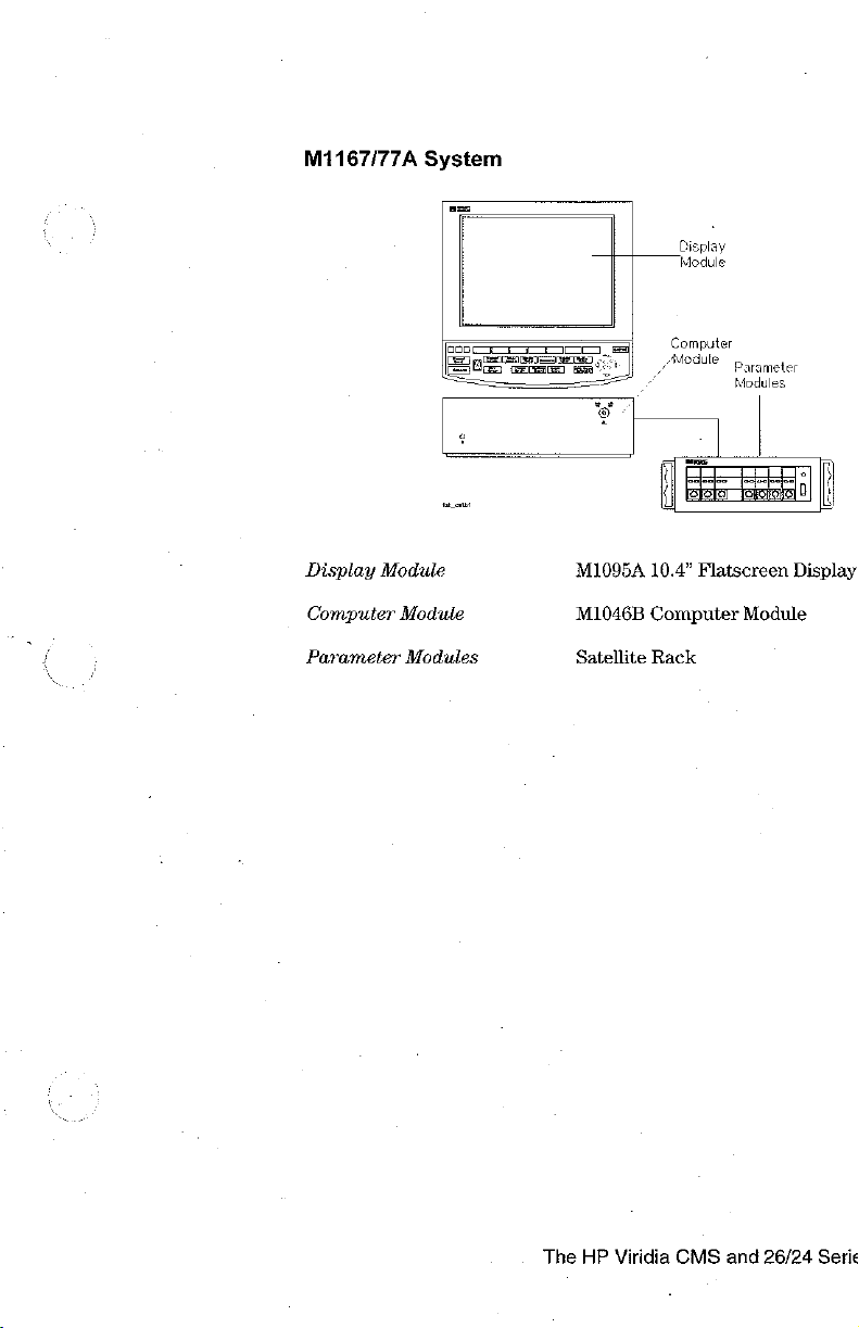
M1167/77A
System
Display
Module
Display
Computer
Parameter
Module
Module
Modules
OO
RU
eae
M1095A
M1046B
Satellite
Computer
Module
a
10.4”
Computer
Rack
parameter
Flatscreen
Modules
Display
Module
The
HP
Viridia
CMS
and
26/24
Serie
Page 28
£a
ο ὢ
|
on
EN
q 5
Ts
oc
cu
FP
同
Introduction
.
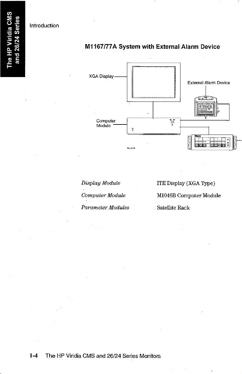
M1167/77A
XGA
Display
System
with
External
Alarm
External
Device
Alarm
Device
Computer
Module
Display
Computer
Parameter
Module
Module
Modules
o
©
ITE
Display
M1046B
Satellite
+
Computer
Rack
(XGA
Type)
Module
1-4
The
HP
Viridia
CMS
and
26/24
Series
Monitors
Page 29
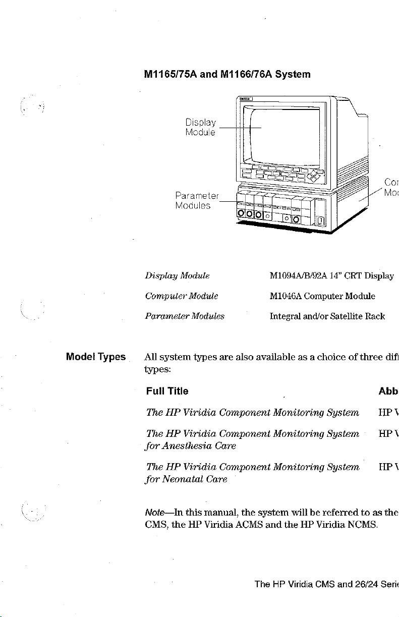
M1165/75A
Display
Module
Parameter
Modules
and
M1166/76A
System
Medel
Types
Display
Computer
Parameter
All
system
types:
Full
Title
The
HP
The
HP
for
Anesthesia
The
HP
for
Neonatal
Note—In
CMS,
the
Module
Module
Modules
types
Viridia
Viridia
Viridia
this
manual,
HP
Viridia
are
Component
Component
Care
Component
Care
also
the
ACMS
M1094A/B/92A
M1046A
Integral
available
-
Monitoring
Monitoring
Monitoring
system
and
will
the
14"
Computer
and/or
Satellite
as a choice
System
System
System
be
referred
HP
Viridia
CRT
Module
of
three
to
NCMS.
Display
Rack
dif
Abb
НРУ
HP
HPA
as
the
\
The
HP
Viridia
CMS
and
26/24
Serie
Page 30
の
=
o
E
Ki
z
>
a
=
a
=
E
©
©
a
に
N
я
S
N
>
=
o
n
ON
Introduction
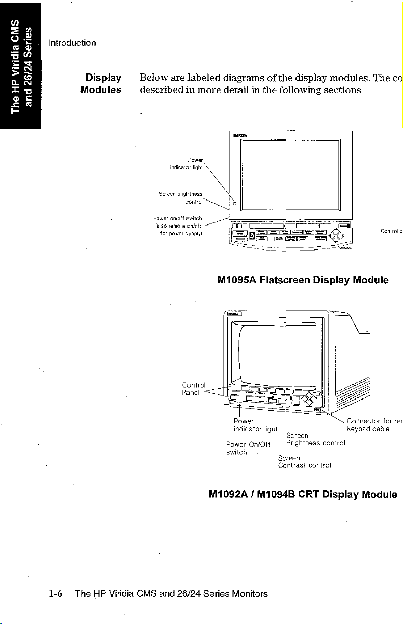
Display
Modules
Below
are
described
indicator
Screen
brightness
Power
on/off
(also
remote
for
power
labeled
in
more
Power
light
control
switch
on/oft
supply)
diagrams
detail
mama
è
in
the
of
the
following
display
sections
modules.
The
co
1-6
The
HP
Viridia
CMS
and
Control
Panel
26/24
indicator
Power
switch
M1092A / M1094B
Series
Monitors
light
On/Off
Screen'
Contrast
Screen
Brightness
contro!
CRT
Connector
keypad
control
Display
for rer
cable
Module
Page 31

Viridia
Series
26/24
Each
1.
Viridia
model
One
26/24
of
two
monitor
Series
types
you
monitor
of
Display
have
consists
Modules,
purchased—either:
of
two
depending
individu:
on!
a. À monochrome
b. A color
2.
The
The
HP
Viridia
AC
power
by
rechargeable
“HP
Viridia
Viridia
Viridia
Model
Rack
with
Models
supply.
Model
Model
Model
26C
batteries
24,
flat
panel
24C,
and
Parameter
24,
The
HP
26CT/24CT
display
or
display
the
the
HP
Modules
24C
and
Viridia
or
by
connection
Power
with control panel
with
HP
Viridia
Viridia
26C
are
Models
Supply”
control
Model
24CT
panel
Model
26CT.
powered
and
to
an
AC
on
page
supp
su]
24CT,
by
26CT
powe
1-14
t
co
«
The
HP
Viridia
CMS
and
26/24
Serie
Page 32

a
=
ο
$
은
=
>
a
т
=
E
の
2
는
Introduction
©
の
=
인
a
©
Control
a
>
Panel
=
v
σ
Softkeys
The
The
the
are
control
softkeys
labels
displayed
on
the
panel
perform
screen,
consists
multiple
at
the
the
softkeys
of
softkeys,
functions.
bottom
do
of
the
not
function.
hardkeys
Their
screen.
and
alarm
functions
When
no
c
s
Hardkeys
The
hardkeys
The
hardkeys
level
where
immediate
example,
waveform.
Note—If
Device,
and
panel
the
entering
of
have
are
adjustments
action.
[Realtime
you
are
handheld
data.
the
other
only
labeled
The
Record]
using
keypad
It
contains
systems.
one
in
and
keys
the
M1167/77A
function
blue.
Each
changes
are
labeled
key
allows
is
the
all
the
defined
one
can
according
you
system
only
means
softkeys
by
of
these
be
made
to
start a recor
with
of
available
the
label
keys
or
perfe
to
their
the
Exte
operatin:
on
c
g
f
t
1-8
The
HP
Viridia
CMS
and
26/24
Series
Monitors
Page 33

Alarm
Lamps
The
alarm
lamps
are
lit
when a red
or
yellow alarm
conditi
Alarm
ЕЕ
af
ct
Sieme
p
Reset
Suspend
Lamps
|
|
siLENE7RESET
key
Alarm
ae
Se
=
=
k
Alarms.
|
Aiams/
Volume
Main
Steen
コ
=
(
К
=
4
suspended Lamp
EPE
Other
Patients
Monitor
||
procadures
[|
Tends?
Setup
Realtime
||
Change
Screen
ji | Record
Alarms
Viridia
Delayed
Record
Suspended
CMS
ЦС)
1996 )
[660 | =
Reale).
Record
Viridia
[Delayed
Record
26/24
EF
Series
||
Gales | Setup
[Airway
|
Sign
Control
ЕС)
Je)
Control
Module
a
Gases
ventitation
Panel
Panel
À
G
トノ
S
Note—Earlier
instead
of
the
versions
of
the
HP
Viridia
[Trends/Cales ] key.
The
HP
Viridia
Model
CMS
and
24
feature
26/24
<
Serie
Page 34

n
=
о
Bj
=
=
>
o
т
©
=
に
ドリ
の
=
Introduction
a
の
+
N
=
の
The
CN
で
Handheld
[=
Keypad
©
(Viridia
The
handheld
are
available
entry
keys
marks,
and
CMS
only):
keypad
on
the
which
arithmetic
consists
control
enable
symbols.
you
of
panel.
to
enter
the
same
In
addition,
letters,
softkeys
the
numbers,
and
keypad
pun
ha
|
Note—The
M1167/77A
handheld
System
a]
with
Mm
60
keypad
is
the
External
only
Alarm
means
Device.
4
SAD
555550056
5005900000
of
©
operating
Softkeys
Data
1-10
and
Hardkeys
Entry
Keys
The
HP
y
Viridia
The
softkeys
position
panel.
The
data
*
To
simply
CMS
and
and
entry
enter
26/24
and
hardkeys
operate
keys
numbers
press
the
Series
in
the
are
located
and
keys
Monitors
on
the
keypad
same
manner
on
the
arithmetic
you
want.
are
as
the
bottom
symbols
in
the
keys
half
(labeled
same
on th
of
the
r
k
in
Page 35

*
until
To
enter
normal.
letters
key.
and
The
lamp
is
pressed
punctuation
in
the
again.
The
marks
key
(labeled
lights
softkeys
up
and
in bl
and
hardk
External
Alarm
Device
(Viridia
Since
ITE
181108,
contain
conjunction
mounted
CMS
the
External
displays
the
any
onto
only):
that
Alarms
hardkeys
with
the
Alarm
Device
do
not
have a contro!
Suspended Lamp
or
softkeys
the
Handheld
External
Alarm
is
used
and
and
therefore
Keypad.
Device
only
with
panel,
the
loudspeaker.
The
Handheld
as
illustrated
comme:
it
contains
can
only
Key
bel
a
I
b
The
HP
Viridia
CMS
and
26/24
Series
Page 36

の
=
ο
3
©
=
>
a
工
o
£
E
の
©
=
Introduction
の
の
+
N
=
©
Hardkey
N
で
Functions
я
©
Silence/Reset | -
or,
if
alarms
is
indicated
screen
wave
affected).
are
-
press
by
layouts
movement
press
latching,
to
suspend
the
Alarm
-
press
-
(Viridia
or
to
access a 2nd
on the
to
silence
to
Suspend
to
return
screen
reset
or
to
CMS
(INOPs,
an
alarm
them.
switch
Lamp.
the
main
only)
or
3rd
display.
alarms
or
alarms
on
all
alarms.
*
monitoring
press
to
You
and
that
The
scre
change
can
numeric
a
+
b
al
Realtime
recorder
Delayed
longer
review
Other
your
characteristics.
such
analysis,
particular
Trends/Calcs | -
trends,
view
Module
settings,
Record] - press
or a bedside
Record ] -
on
the
monitor
-
press
alarm
limits,
Patients] - press
group.
-
press
as
Cardiac
Drug
Calculations,
patient
make
and
in
graphs.
Setup | -
switch
recorder.
press
screen.
to
enable
enter
to
-
press
to
to
enable
Output,
case
and
press
to
review
press
to
parameters
to
record
to
record
you
Monitor
enable
enable
Wedge
admit
transfer
enable
calculations,
enable
on
pre-selected
pre-selected
to
suspend
Standby,
you
you
you
to
Pressure (Viridia
and
patient
you
you
or
off,
or
or set
to
view
to
pre-select
set
up
discharge
data.
to
view
print
reports
to
change
or
set
up
waves
waveform:
switch
the
data
from
certain
and
perform
CMS
patients,
vital
signs
or
adjust
parameters.
on
and
ont
alar
alarn
oth
s
p
on
«
an:
ma
p:
1-12
The
HP
Viridia
CMS
and
Keys
26/24
Series
Monitors
Page 37

The
arrow
when
illuminated.
operating
procedures,
This
CONFIRM...”
key
functions
screens
keys
or
Key
appears
consist
The
to
make
only
of
up/down/left/right
arrow
keys
enable
changes
when
on
the
you
to
to
the
it
is
screen
keys.
They
allow
you
to
move
betw
change
illuminated. A prompt
screen
when
or
adjust
display.
you
need
setting
to
o1
m
use
Airway
gases
Gases/Ventilation] - (Viridia
or
ventilator
waves
and
numerics.
CMS
only)
Press
ti
The
HP
Viridia
CMS
and
26/24
Series
Page 38

W
=
ο
=
=
=
>
a
Ir
の
=
同
=
n
+
N
EN
©
N
Ὃ
E
©
a
©
HP
Viridia
Model
o
HP
Viridia
26CT/24CT
Model
Power
26CT/24CT
The
HP
Viridia
(line
power)
monitoring
recommend
the
monitor
monitoring.
area,
where
Supply
Power
Models
or
by
needs
that
is
not
When
AC
power
24CT
their
own
will
determine
you
plug
being
moved
transporting a patient
is
not
and
internal
the
monitor
or
feasible,
Supply
26CT
are
battery
which
power
into
used,
or
or
use
battery
powered
power
source
line
or
for
long
when
by an
supply.
is
us
AC
powe
term
be
monitorir
power.
e
Warning
Do
not
disconnect
connected
the
power
monitor
The
power
exposed
cracks,
to
cord.
and
cord
metal
exposed
the
AC
Instead,
unplug
must
parts.
metal
the
power
it
be
Replace
power
keep
from
the
inspected
parts,
cord
from
source.
the
power
AC
periodically
immediately
or
any
This
power
other
the
could
cord
source.
if
signs
monitor
cause
connec
for
there
of
a
«
cr:
ar
we
Battery
Power
Supply
1-14
The
HP
The
lead-acid
battery
power
as
Viridia
for a fully
We
battery
Viridia
CMS
HP
Viridia
batteries
discharge
load
well
as
parameter
Models
loaded system
‧ 1 hour
loaded
ECG/Resp,
* 1 hour
batteries
ECG/Resp,
recommend
life
and
26/24
Models
with
is
dependent
is a function
settings
24CT
and
for a fully
with
the
following
NBP,
15
minutes
when
loaded
NBP,
you
use 2 fully
when
using
Series
Monitors
24CT
and
26CT
12
Volt
2.3
Amp-Hour
on
temperature
of
the
number
being
used.
26CT
ranges
operating
loaded
on
system
parameter
SpOs,
Pressure,
for a minimally
with
the
SpO»,
Pressure.
charged
the
battery
power
can
be
and
type
The
from
approximately
one
battery
operating
modules:
Recorder
loaded
following
batteries
supply.
powered
capacity.
and
power
of
parame
battery
life
to:
on
two
and
system
parameter
to
get
by
]
The
|
fc
bat
opel
1
the
:
Page 39

HP
Viridia
Model
26CT/24
Battery
Specifications
‧
lor 2 lead-acid
+
12
Volt
*
Up
to
1.25
depending
Note—Charging
16
hours
to
90%
DO
Delayed
Record
Note—When
LEDs
may
take
and
may
underreport
fuel
guage
rather
estimate
setting
battery
time.
2.3
Amp-hour
hours
on
time
of
AC
is
some
batteries.
battery
modules
is 4 hours
full
capacity
‘sae
Battery
Charging
connected
time
battery
than
the
capacity
capacity.
capacity
used
to
if
Batt
Charged 7
t
and
to
cycle
capacity
Battery
or
turn
typical
in
the
product.
90%
of
full
the
monitor
ONE
CY
attery
the
monitor
to
the
appropriate
during
Charge
the
LEDs
monitor
on
full
capacity
is
on.
is
on,
the
this
setting
during
off
to
accele
char
if
th:
AC
Power"
B:
char
r
thi:
See
Chapter
information
indicators.
12,
“Battery
on
battery
Information
operation
The
HP
Viridia
and
(Viridia
Battery
CMS
and
26/24
Charge
'
26/24
only)”
LED
Series
Page 40

l'E
=
o
o)
2
=
>
Do
=
©
=
Е
Parameter
Series
26/24
Parameter
and
Modules
Modules
The
parameter
key
labeled
you
directly
the
Setup
setup
window
The
connector
the
corresponding
with
key
modules
into
on
or
socket
have
the
parameter
the
setup
screen
the
front
of
task
window, a light
on
the
connector
Light
for
setup
key
Parameter
setup
key
one
name
the
module,
front
plug
or
for
of
on
more
is
called
that
parameter.
and
appears
each
the
transducer
p
ECG
L
hardkeys
the
get
above
module
M1001B
EI
ECG
그
on
Setup
into
is
or
the
Wher
the
the
the
pat
ke
y
ke
sa
7
1-16
The
HP
Note—If a “7”
settings
rack
Viridia
CMS
may
to
another.
and
26/24
Connector
patient
or
transducer
is
present
be
transferred
This
Series
for
cable
on
the
with
behavior
Monitors
front
that
is
dependent
NU
of a module,
module
when
on a setting
12
PIN
certain
it
is
p
mc
m
Page 41

P:
special
or
(called
Parameter
When
equipment,
modules.
leaks
Service
the
HP
“Parameter
Rack
Type
Viridia
Integral
Satellite
Viridia
8-slot
Satellite
Rack
(Standard)
6-slot
Satellite
Rack
(Optional)
Caution
the
into
service
modules
CMS
Rack
Rack
26/24
rack
do
Severe
the
connectors
Mode,
either
engineer.
Settings
can
be
Mounting
This
is
the
M1046A
module.
You
can
satellite
an
LV.
wall.
Series
Same
Viridia
Same
Viridia
This
can
to
the
Viridia
Monitors
is
mounted
not
let
saline
damage
to
at
by
your
biomedical
You
can
find a description
Transfer”)
plugged
fitted
computer
have
racks
pole,
bedside
as
Satellite
CMS. Rack
as
Satellite
CMS.
also
back
of
24CT
into
to
the
one
or
attached
Rack
Rack
be
mounted
the
M1205A
and
26
in
the
front
or
CT
Chapter
following
of
more
to
for
for
engineeri
3.
Comm
| Cannot
the
System
Can
CMS
Availak
8-slot
Only
witha
Series
in
close
solution
the
equipment
the
rear
proximity
get
of
onto
can
the
to
any
the
rack
result
modules.
of
t
type
M1
be
S:
r
o:
c
intrav
or
|
if
sal
The
HP
Viridia
CMS
and
26/24
Series
Page 42

n
=
о
k
은
=
>
a
=
o
A
e
の
o
=
9
[1]
+
원
=
«o
N
D
=
©
Parameter
Modules
You
can
you
require
the
type
For
most
each
more
If
too
message
message
plug
of
type
than
many
detailing
field:
the
them.
rack
types
per
one
modules
parameter
The
and
of
parameter
patient
per
patient
where
number
the
(ECG,
or
model
an
modules
of
modules
of
monitor
modules,
for
example).
(Invasive
unsupported
the
extra
into
the
Pressure,
module
module
the
rack
you
you
have
system
Other
for
is,
appears
and
can
plug
allows
types
example)
are
rem
in
ordere
o1
of
m
plugge
in
th:
«
Currently
where:
R
is
the
(e.g.
or
P
is
the
(counted
The
message
Unrecognized
is
displayed
Note—Since
rack, R will
ignored
number
1=integral
i=first
slot
if
an
unknown
the
Viridia
always
satellite
number
from
module
be
module
of
the
rack,
left to
26/24
1.
in
rack
2=first
rack,
in
that
right)
in
rack
module
Series
rack
satellite
2=second
rack
position
is
plugged
Monitors
position
rack,
satellite
into
only
R-P
...
rack,
...
R-P
the
rack
support:
1-18
The
HP
Viridia
CMS
and
26/24
Series
Monitors
Page 43

Operating
Levels
There
module.
them
are
three
types
of
are
The
three
shown
Standard
Display
types
below.
screens
of
which
screen
E
DD
and
SEO
Ecs
you
will
the
interconnection
4
SJ
Control
Panel
Selection
ist
Level
Window
see
on
the
2nd
|
Level
The
HP
Viridia
CMS
and
26/24
Series
Page 44

2»
©
o?
so
LR
~
>3
EQ
Tau
=
2%
[=
Operating
Main
Screen
Levels
This
display
parameters
label,
date
You
can
configure
display
The
model,
the
The
Screen.
screen.
numeric
the
corresponding
hardkey
DAVID
shows
you
have
and
time,
the
The
information
numeric
waveform.
SCHULTZ
キー
イサ
ンー ヤ サー
amy
the
waveforms
chosen
and
arrhythmia
number
numerics
is
appears
to
monitor,
and
are
aligned
updated
in
the
always
Bed & Adult
wore
and
numerical
alarms,
messages
position
with
every
two
same
color
returns
14
FEB
99
(when
of
the
the
seconds.
thet
you
directly
20:00
readouts
INOP
mes
assig
wavefor
correspc
Wi
you
hav
to
Non-
эта
0ῇ
t
120
The
HP
Viridia
Note—The
Alarm
Volume
CMS
and
Main
Screen
Control
26/24
Series
of
the
and
QRS
Monitors
Viridia
Volume
26/24
Control
Series
Monitors
Bars
(see
Page 45

CHANNEL
LAYOUT:
#1
#1
NON-OVERLAP
CHANNEL
#42
一]
—
ICU
Adu
10
JAN
98
20:08
HR
ts
CHANNEL 一 |
CHANNEL
44
一
—
J
Atarm
Vol165_ 1 圖 1 orsvoiiso
1
The
HP
Viridia
CMS
and
26/24
Series
Page 46

т
=
o
Z
=
=
>
a
=
o
A
に
Operating
Series
Selection
26/24
Window
and
Levels
This
is
the
or
function.
You
get
hardkeys
When
you
active.
The
time.
There
This
selection
For
is
selected
Window
avr
Bo
first
operating
into a Selection
on
the
control
get
into
the
Selection
is
indicated
can
be
changed
information
aiso
an
line
when
to
which
DAVID
SCHULTZ
lp
tmy
arrow
the
the
a
da
on
symbol
arrow
level
Window
panel.
by a bar
how
cursor
is
Bed 6 Adult
dado
where
you
by
pressing
Widow
below
the
within
the
to
change
in
the
Window
keys
are
pressed.
pointing,
16
РЕВ
press
pe
can
choose a spe
one
the
bottom
keys
and
Selection
the
selection
that
To
99
19:27
nd
8 0
στι
Cp
of
the
line
the
Window
moves
enter
HR
sm
ABP
blu
is
ye
see
p
a
th
.
Non-pz
00
00
1-22
The
HP
Viridia
CMS
and
26/24
Series
Monitors
Page 47

Task
Window
This
is
the
second
adjustments
procedures. Each
There
via
or
by
are
two
the
for
parameters:
pressing
BAVIB
四
TOO
Monitor,
u
to
the
ways
Selection
SCHULTZ
tmy
tmy
operating
parameters
parameter
to
get
Window,
the
Setup
Mode:
automatic,
>-
level,
or
into
key
pu
-MN
which
and
screen
procedure
the
second
on
the
Adult
16
Alarm
AA
allows
displays,
has a series
operating
parameter
FEB
97
20:55
“Bo
Limits:
EA
you
or
module.
ABP]
Ed
cur
50 - 12
to
ma
to
E
of”
level:
2
9
0
E
Change
Lees
||
The HP
Viridia
CMS
and
26/24
Series
Page 48

の
=
o
Re!
은
=
>
a
=
a
<=
[πο
a
ο
=
Operating
©
の
bui
N
=
©
Getting
N
=
the
=
©
Operating
Levels
Levels
into
Before
or
levels
procedures
you
can
start
perform a procedure,
and
how
to
below
to
make
you
navigate
to
get
into
adjustments
need
to
through
the
Selection
know
the
selections.
or
changes
how
and
to
Task
to
get
into
Follow
Windc
th
t
Selection
L
Press
2.
When
active.
by
window,
Press
function
Window.
For
example,
Window:
1.
Press
2.
If
it
pressing
Press
Pressure
Task
Window
There
are
via
Window
the
blue-labeled
you
Select
pressing
or
either
you
to
the
hardkey
is
not
already
[Module
the
softkey
Task
two
ways
the
Selection
get
into a Selection
the
line
the
same
hard
use
the
arrow
the
softkey
require
get
into
or
the
[Module
active,
Setup | again.
“NBP:
Window.
to
get
into a parameter
Window,
hardkey
for
Window,
with
the
parameter
key
again
keys
if
corresponding
Noninvasive
Setup
select
the
to
get
into
the
that
they
.
This
Blood
line
the
Task
function
the
are
to
gets
you
bottom
or
function
got
you
illuminatec
the
parame
you
Pressure
containing
Noninvasive
Window,
r
li
into
into
(1
№
]
«
1-24
The
HP
Viridia
CMS
or
by
pressing
you
and
26/24
directly
Series
the
into
Setup
the
Task
Monitors
key
on
the
Window.
parameter
module
v
Page 49

Getting
Monitor
Window
for
labeling.
into
the
parameter
Setup
there
In
screen.
There
are
you
will
either
adjustment
1.
To
move
function
into
necessary
2.
To
make
softkey
want
other
Task
is
only
are
separate
or
addition
two
to a setting.
the
is
the
reasons
want
to
to
the
you
require,
Filter/Mon/Diag
adjustments.
an
adjustment,
for
that
active,
or
Windows
possible
keys.
function
selected keys
for
changing
move
to
next
Task
for
window
use
the
for
via
the
The
you
have
the
Window,
example
Task
change
again,
arrow
functions
Selection
selections
chosen
appear
the
selection
next
Window
the
until
keys
like
Window.
are
to
Task
Window,
press
the
:Filter/Mon/Diag:.
where
selection
the
adjustment
if
they
Other
that
are
indicate
be
“pushe:
in
the
softkey
you
by
are
I
I
ct
Ta
or:
Т
cai
pres
c
illum
The
HP
Viridia
CMS
and
26/24
Series
Page 50

の
=
o
e)
Ki
E
>
a
k
o
=
ㄷ
The
Series
26/24
The
and
Viridia
CMS
Viridia
Computer
CMS
The
computer
screen
Modules
Computer
signals
from
module,
as
waveforms
Modules
the
parameters
where
and
being
they
are
numerical
monitored
processed
readouts.
and
are
then
trans
disp
M1046A
Computer
Module
The
M1046A
the
HP
M1175/76A
Integral
with
modules
ECG
Connector
The
a
satellite
rack
parameter
Output
parameter
blank panel
parameter
Computer
and
for
satellite
module
can
Module
Viridia
Defib.
Marker
rack
CMS.
Maximum
Input
is
for
use
Voltages
with
Connector
satellite
3.2 V p-p
60
the
V
HP
ECG
Defib.
rack
M11¢
Out
M:
for
rack
can
be
be
fitted
module
to
the
rack.
attached
computer
to
the
module
comput
if
you
x
1-26
The
HP
Viridia
CMS
and
26/24
Series
Monitors
Page 51

M1046B
Computer
Module
The
CMS.
M1046B
Computer
ECG
Defib.
Output
Marker
Module
Computer
and
/
Input
is
for
use
Module
The
with
Satellite
with
parameter
Viridia
the
HP
rack
modules
CMS
M11!
C
ECG
Output
and
Defibrillator
Marker
Input
ECG
Output
and
Defib.
The
parameter
They
cannot
Applies
The
ECG
computer
waveform
marker
discharge
If
pulse
defibrillator
that
used
pump
you
are
from
recorder
for
systems.
pulse
modules
be
attached
to
both
the
M1046A
output
other
and
defibrillator
module
for
in
using
the
is
used
synchronizing a defibrillator.
from
the
the
ECG
waveform
an
HP
defibrillator
has a built-in
rather
than
applications,
Maximum
Marker
are
defibrillator
defibrillator
The
Input
inserted
to
the
front
and
during
is
returned
recorder,
to
the
monitor.
such
HP
Viridia
Voltage
into
one
of
the
M1046B
marker
cardioversion
on
as
input
for
indicating
the
monitor
without a built-in
to
the
then
the
The
synchronizing
CMS
3.2 У р-р
or
several
computer
Computer
connector
to
provide
It
is
also
the
display.
monitor.
marker
ECG
and
26/24
sa
mod
Mods
used
|
defib
recor
If
tl
pulse
output
intra-ac
Series
Page 52

Zo
や
Oz
mo
50
ES
> お
LN
エ で
ο
ς
z
©
Е
The
The
Viridia
26/24
Viridia
Series
Parameter
26/24
The
Virida
module
In
addition,
slot
rack
Warning
Do
not
Model
mainframe.
communication.
The
signals
internal
screen
Module
Series
26/24
by a cable
the
directly
Rack
Parameter
Series
to a connector
HP
Viridia
to
connect a second
24CT
or
26CT
Docking a second
from
the
computer,
as
waveforms
where
parameter
Models
the
mainframe.
rack
with a 6
parameters
they
and
numerical
Module
module
on
the
24CT
by a cable
wide
rack
being
are
processed
readouts.
Rack
rack
is
left
side
and
26CT
when
rack
docked
by a cable
monitored
and
attached
of
the
dis
allow
yor
using
to
the
may
dis!
are
trans!
then
disp.
1
t
1-28
The
HP
Viridia
CMS
and
26/24
Series
Monitors
Page 53

Operating
Rt
Operating
Rules
‧
*
*
*
e
*
to
Remember
Pressing
To
get
into a Selection
What
is
Softkeys
exception
Control
The
parameter
Window.
The
arrow
for
use.
labeled
function
of
the
on
the
keys
in
yellow
only
Alarm
Viridia
module
and
key
Window
and
in
the
Volume
26/24
Setup
always
returns
press a hardkey.
appears
Selection
Series
key
key
“pushed
Control
Monitors).
gets
you
are
illuminated
you
and
and
directly
Task
the
to
in”
Wir
QRS
the
is
ir
w
The
HP
Viridia
CMS
and
26/24
Series
Page 54

Performance
Specifications
of
the
HP
Displays
Performance
M1095A
Flatscreen
Display
Pixel
M1094A/B
and
M1092A
CRT
Display
Specifications
Useful
Screen:
(25%
unless
otherwise
Size
Storage
Trace
Useful
(15%
Time
Speeds
Screen:
unless
at
25
otherwise
noted)
mm/sec
noted)
of
the
158
0.33
5.5
seconds
6.25,
180
HP
Displays
mm x 211
mm x 0.33
12.5,
25,
mm x 225
mm
(6.2” x 8.3”)
mm
50
mm/sec
mm
(7.1” x 8.9”)
£10%
1-30
The
HP
Pixel
Storage
Trace
Viridia
Size
Time
Speeds
CMS
and
at
25
26/24
mm/sec
Series
0.22
6
6.25,
Monitors
mm x 0.35
seconds
12.5,
25,
mm
50
mm/sec
+10%
Page 55

Usi
Using
Safety
an
ITE
Display
The
M1167A/77A
displays.
the
there
compliance
Device
*
*
*
display
are
Directive)
Safety
EMC
Performance
1.
The
EN60601-1
it
must
standard
1-1
EN60601-1
—
—
There
additional
+A1
Viridia
are
is
used
with
the
display
+A1
conform
and
{IEC601-1-1 + Al}
CMS
several
as
requirements
and
must
fulfill
restrictions
part
of a medical
European
with
FDA
Requirements
either
+A2
{TEC601-1
to
the
specific
{IEC601-1}:
The
display
of
liquids
safety
The
ITE
(e.g.
HP
requirements
condition).
transformer cannot
does
hazard
display
M1389A),
The
must
not
(IEC601-1;
must
of
EN60601-1/1£C601-1
power
provides
Council
comply
means
associated
device within
to
be
fulfilled
recognized
with
+A1
requirements
requirements
to
provide
be
constructed
wet
parts
44.3).
be
used
if
the
enclosure
cable
be
disconnected
for
in
Directive
consensus
the
requiremen
+A2),
or
of
an
according
the
same
or
protected
of
the
display
with
an
leakage
must
be
without
custome
with
thi:
the
order
93/42/EE
sta:
IEC
XXX
level
whic
isolation
curr
(normal
secured
p
tc
«
‹
s
a
si
th
2.
Atest
condition)
performed
of
the
Enclosure
of
the
and
Leakage
complete
documented.
The
HP
Viridia
Current
system,
CMS
(normal
including
and
26/24
the
Series
ап.
dis
Page 56

Using
an
ITE
Display
EMC
Perfor-
mance
Reguire-
ments
Specification
Resolution
Vertical
Red,
Vertical & Horizontal
Video-Cable
Refresh
Green
(pixel
Rate
and
Blue
Connector
1.
The
display
(IEC
601-1-2),
it
must
devices,
2.
The
video
display
3.0m
EMC
HP
cannot
Cardiac
displays.
sweep-speed
Displays
display
addressability)
Video
Muiti-Sync
assure
Monitors,
Compliance
M1092A,
specifications
Inputs
must
either
or
conform
EN50082-1:
must
specifications
Inputs | 5
to
cable
between
not
exceed a length
testing
according
compliance
Heartrate
with
M1094B
are
Requirement
1280 x 1024
60
-0.7
HDi5male
the
1997
the
recommended:
fulfill
the
requirements
and
EN50081-1 / CISPR
M1167A/77A
to
with
the
Meters
can
and
and
ECG
aspect
only
M1095A.
requirements
of
the
Viridia
of
3.0m.
IEC
801-4:1988
ANSVAAMI
Alarms
ration
be
assured
In
addition,
or
Value |
EMC
For
EC-13
when
and
when
Units
Dots x li
Hz
Vp-p
VTTL
of
the
stan:
22.
CMS
an
cables:
has
to
using
25
mi
usin;
the
fol
(non
S
1-32
The
HP
Viridia
CMS
and
26/24
Series
Monitors
Page 57

Now
that
probably
started.
*
Setting
*
Setting
se
Attaching
you
ready
It
contains
up
up
have
to
the
the
the
been
start
using
the
following
Monitor
Parameter
Patient
Getting
introduced
it.
(Viridia
...................
to
This
chapter
sections:
26/24
Modules
the
monitc
only)
........
£
will
.
Get
Page 58

Setting
up
the
Monitor
(Viridia
26/24
only)
Started
Getting
Setting
up
the
Monitor
1.
Attach
cable
are
using
slot
rack
a
cable.
(Viridia
the
parameter
to
the
connector
the
HP
to
the
The
two
26/24
module
Viridia
back
of
components
on
the
Model
the
mainframe
only)
rack
to
left
side
24CT
will
snap
the
display
of
the
or
26CT
display
or
display
you
withou
dock
moc
n
can
toget
2-2
Getting Started
Page 59

2.
Ifyou
batteries
Amp-hour
door
with
pointing
when
are
using
are
sealed
in
the
back
the
grey
into
properly
the
not
already
lead-acid
of
HP
battery
the
monitor.
inserted.
HP
the
monitor.
Viridia
in
place,
batteries
label
The
Setting
Model
up
24CT
insert 2 HP
into
The
batteries
facing
upwards
batteries
the
Monitor
and
the
will
(\
26CT
40488A
spring-k
should
and
th
snap
or
|
Caution
Hewlett-Packard
the
HP
Viridia
into
an
AC
power
the
monitor
hours
for
the
power
to
charge
3.
is
for
the
batteries
and
external
the
Ifusing
plugged
batteries
batteries.
an
source.
recommends
Models
supply
to
be
fully
battery
AC
power
you
24CT
or
26
(line
power)
in
and
the
power
to
reach a charge
charged.
charger
supply,
fully
CT
for
If
is
plug
charge
the
for
an
is
of
the
on,
the
the
first
initial
off,
it
90%
capacity
monitor
it
takes
power
batteri
time.
chargin
takes
app
is
pluge
approxir
cord
Getti
Ph
a1
int
Page 60

Started
Getting
Setting
up
the
Monitor
(Viridia
26/24
4.
Switch
then
Warning
Connecting
product
is
monitoring
the
product
To
prevent
interface
HP
Viridia
only)
on
the
performed.
the
HP
Viridia
powered
network
will
recover
unintentional
cable
is
properly
monitoring
system
on
is
not
(SDN)
the
disruption
network
using
the
monitoring
supported.
interface
product.
secured
at
(SDN).
power
network
Error
lock-up
No
permanent
in
monitoring,
both ends
On\Off
(SDN)
codes
may
when
switch.
cable
and
occur.
damag,
be
sure
conn
H
Po
1
2-4
Getting
Started
Page 61

Setting
up
the
Pz
Setting
up
the
Parameter
1.
2.
3.
Decide
Make
sure
insert
module
upwards
Check
plugged
to
the
Modules
which
the
the
module
clicks
and
~
that
you
into
patient
parameters
appropriate
into
into
place.
pull
the
module
have
the
the
modules.
cables
and
you
want
modules
the
rack
until
To
remove a module,
out.
correct
The
module
transducers,
to
monitor.
are
the
(See
p
patient
for
plugged
lever
diagram
cables
connectors
easy
into
on
press
belo
and
ident
the
NN
t
ai
Your
monitor
understand
to
Parameter
may
the
effect
Settings
have
this
Parameter
has
when
Transfer
Settings
using
in
Chapter
Transfer
modules
3.
set
with
Get
|
th
Page 62

Attaching
the
Patient
Started
Getting
Attaching
the
Patient
1.
Attach
catheters
2.
Connect
modules.
After
less
similar
waveforms
displayed
The
to
numerics
the
than
the
one
depends
and
also
are
electrodes,
as
required
the
electrodes,
10
or
20
under
on
on
the
aligned
probes,
for
probes
seconds
“Main
the
waveforms
model
with
transducers,
monitoring
and
you
should
Screen”
in
you
of
your
the
corresponding
and
the
patient.
transducers
see a display
Section
have
selected
system.
waveforr
1.
inser
to
The
th
01
nu
ti
2-6
Getting
Started
Page 63

Atte
Adjusting
Screen
|
Contrast
Viridia
The
the
the
Models
Make
26/24
Series:
brightness
dial
located
monitor.
24C,
sure
The
24CT,
that
or
contrast
behind
HP
26C
all
of
of
the
edge
Viridia
and
the
screen
the
screen
of
Model
26CT
are
information
display
the
display,
24
uses a contrast
equipped
is
Screen
Screen
can
be
adj
on
the
lowe
conti
with a brigl
visible.
Bright
(Model
26/24
Contras
{Model
2:
Viridia
The
brightness
means
Follow
1.
2.
of
Turn
settings.
Slowly
acceptable
most
light
visible.
CMS:
the
two
this
procedure
the
tum
acceptable
conditions.
and
contrast
dials
underneath
to
brightness
the
brightness
position
position
Please
of
the
achieve
and
contrast
where
will
ensure
screen
the
the
and
the
be
display
hardkeys.
optimum
controls
contrast
display
dependent
that
all
can
screen
to
controls
can
still
upon
the
screen
be
disp
their
dov
be
Gett
a
m:
se
the
inf
Page 64

5
の
E
£
n
a
£
トコ
|
o
Attaching
the
Patient
Starting
Monitoring
DAVID
р:
hap
vr
ην
LETH
RESP
Le
The
patient's
configured
were
set
up
(‘Parameter
SCHULTZ
la
kn
v
У
aa
人
FAN
ーー…
NOSIS
vital
signs
default
settings
at
installation
Settings
Bed é Adult
En
ta
ー
are
now
for
the
or
have
Transfer”),
16
FEB
99
oy
PW
cs
appearing
parameters
been
stored
are
active.
19:27
gp
1
WW
197
on
HR
Non-pace
эт!
00
se
ABP
20/80
2
8
RESP
the
screen.
and
screen
in
the
modu
e
€
(
9
2
1
1
T
d
Screen
Messages
2-8
Getting Started
If
you
want
“Configuring
parameter
Switch
the
Alarm
Two
*
*
settings
the
Suspend
types
of
Prompt
Status
situation.
“sync
to
make
changes
the
System”.
see
the
system
alarms
lamp
goes
messages
messages - these
messages - these
For
output
appear
instance:
not
to
the
If
you
want
individual
ON
(by
pressing
out).
at
the
instruct
give
information
available,
screen
to
make
parameter
The
patient
top
of
the
display
changes
sections.
the
is
the
display
user
to
about
plug-in
see
the
now
bein
scr:
perform
the
ECC
s
to
]
ct
Page 65

this
message
stays
as
long
as
the
ECG
module
is
Att
not
Reserving
Channei
Prompt
Window,
operating
On
below
In
appropriate
a
A
channel
There
use
assigned
This
same
waveform
Note—
previous
deleted
“Discharging a Patient/Ending a Case"
and
or
level.
the
Main
the
alarm
Prompt
Status
the
Task
parameter
where
is
no
its
screen
wave
ensures
place
trend
patient
if
the
status
at
the
Screen
and
messages
message
Window
user
action
module
the
waveform,
channel
is
reactivated.
that
particular
on
the
display
data
should
monitor
messages
top
of
display
INOP
are
the
may
waveform
waveform
temporarily,
Main
of
different
for
this
has
are
the
Main
the
messages.
appear
displayed
prompt
is
performed.
be
turned
should
waveforms
Screen,
patients
patient
be
deleted.
been
displayed
Display
prompt
for 3 seconds.
in
and
label,
but
and
is
The
shut
and
rotation
status
OFF,
but
be
still
or
will
can
avoids
in
the
to
be
old
off
for
on
either
screen,
messages
numeric.
be
always
inconsistencie
collected,
data
three
page
in
the
dependi
status
messa
for 3 secon
left
in
appears
Anoth
discarded
be
same
depart:
will
hours
7-9
for
rem.
the
on
old
be
ap
ra
th
¢
allo
d
a1
or
mo!
Get
Page 66

Attaching
the
Patient
|
E
8
Y
E
o
A
S
に
=
©
Power
Failure
Patient
information
Center
If a power
monitor
alarm
Settings
Caution
You
are
The
monitor
Less
than
Less
than 3 hours
More
than 3 hours
Tf
the
monitor
78504
and
2,
Center.
failure
will
limits
stored
Transfer”
advised
60
and
HP
the
wave
occurs,
NOT
be
in
on
to
check
reacts
according
seconds
is
connected
78508)
is
not
any
alarm
retained
“7”
page
when
modules
3-61.
all
the
to
Patient
settings
Patient
settings
Patient
All
settings
setting
to a Patient
and
you
select
displayed
conditions
power
ARE
retained - see
monitor
the
settings
length
Data
Management
retained.
Data
Management
revert
Data
Management
revert
may
be
Information
the
same
in
channel 2 of
that
is
restored.
of
the
to
user
to
user
lost
if
not
lead
the
were
si
Sett
“Par:
after
any
power
defaults.
fa:
data
:
data
data
defaul
netwo)
Center
for
ECG
Patient
1
1
Monitor
Standby
2-10
Getting
Started
If
you
want
Data
Management
“Monitor
1.
2.
All
suspended.
Standby”:
Press
Press : ‘Monitor
waves
and
to
stop
patient
information,
[Alarms/
numerics
The
word
monitoring,
Volume]
Standby.
disappear
“Standby”
you
or
[Alarms
appears
can
from
but
keep
switch
]
the
in
big
all
the
monito;
display,
letters
setting:
and
all
on
tt
Page 67

If
your
monitor
the
monitor
over
the
system.
“Standby”
Central
bed
Alarm”
tone
displayed.
To
on
(Viridia
settings
Management
also
As
monitor
Station.
in
the
is
(two
resume
the
control
CMS
before
retained.
all
monitoring
is
is
connected
is
in
standby,
Instead, a message
is
sent
to
If
your
system
displayed
double
monitoring,
in
goes
beeps),
panel
only).
going
information
is
Monitor
to
an
no
parameter
other
beds
in
the
bed
is
configured
into
alarm,
on
your
monitor.
but
the
Alarm
simply
on
the
The
into
suspended,
Standby.
press
front
of
changes
Monitor Standby
collected before going
and
no
HP
Viridia
data
indicating
system,
to
the
status
You
will
Bed
one
of
the
display
adjustments
patient
data
patient
from
that
and
receive
message
hear
Task
the
keys
or
are
retained.
into
is
Att
care
your
m
your
m
is
displa
alarm:
“Ot!
the
ove
Window
(exce
on
the
h
that
you
P
Mon:
collecte
The
Standby,
resume
hardkey
so
you
can
monitoring.
operates
prepare
the
as
usual
monitor
when
alarm
you
are
i
capability
Getti
Page 68

Started
Getting
Attaching
the
Patient
2-12 | Getting
Started
Page 69

Setting
This
can
key.
chapter
be
It
describes
changed
includes:
during
the
following
up
the
monitoring,
your
characteristics
sections:
using
of
the
M
your
[Mos
Changing
Selecting a Screen......................
What
Changes
Assigning
Selecting
Changing
Selecting
Displaying
oxyCRG
CSA
Configuring
Display
you
Can
to
Waves
the
the
Realtime
Split
Display.
Display
Screens
Configure.................
the
Configuration
to
Screen
Number
Wave
Overlap...:..........
Wave
Screen
....................,..
(Viridia
aSecondIndependent
...............
............
Channels.
of
Waves...........
Speeds..........
Trends . ..........
CMS
only)
..........
Display
.....
8-32
Adjusting
Adjusting
Selecting
Configuring
Other
The
The
Changing
Changing
Changing
Changing
The
Parameter
the
the
Waves
Patients
Status
Monitor
Default
the
the
Operating
Test
Signals
Votume
Date
and
for
Central
Module,
Controls
Log
Function.
Revision
Settings
Patient
Configuration
Modes
Function
Settings
Transfer
Control............
Time.............
Recorders
Bedside
Function...........
Category
and
Central
and
Patient
...........
Set...........
..............
...............
.............
Cate:
(
....
R
Setting
up
y
Page 70

Changing
Display
Screens
L
5
ο
>
e
5
D
£
E
©
0
Changing
=
©
è
=
ο
=
Display
A
display
numerics
screen
specific
There
default
D
and
Standard,
A
softkey
Screen
(Viridia
an
inactive
You
can
of
the
You
can
display
user
changes
switched
Screens
screen
and
overlayed
can,
for
instance,
procedure
are
five
separate
names
Screen
Task
other
screen
of
E.
or
Surgeon)
corresponding
Window
26/24
Series).
softkey
change
softkeys.
reconfigure
has
them,
off,
the
is a pre-selected
application
be
created
in a department
display
these
screens
You
can
select
for
these
to
each
(Viridia
The
for
that
to
one
only
been
or
the
settings
CMS)
display
screen.
of
the
other
the
screen
configured,
monitor
automatically
arrangement
of
windows. A particular.
to
monitor a patient
or
unit.
screens
are
additional
which
Screen
can
A,
Screen
screen
screens.
screen
or
the
screen
screens
which
the
is
switched
is
available
Monitor
which
at
any
is
currently
settings
off.
revert
to
is
remain
realtime
be
confis
B,
Scre
labels
in
the
Setup
active
time,
by
acti
When
the
defaul
\
du
(su
€
T:
is
eit}
th
3-2
Setting
up
your
Viridia
the
“Next
Window.
Monitor
CMS
only:
Display::
This
key
If
you
softkey
is
used
have a second
is
available
to
configure
in
the
or
third
the
Change
second
independe
Screet
or
third
¢
Page 71

Selecting a Screen
If
the
screen
must
select
C,
screen D or
you
the
Screen
want
to
required
E).
change
screen
is
(for
not
the
example,
currently
Screen
activ
A,
Sc
th
Procedure
1.
2.
Press
Press
The
Main
the
hardkey
the
softkey
Display
(Viridia
26/24
corresponding
appears
for
(Viridia
Series).
to
the
screen
the
selected
CMS)
you
screen.
oi
w
Setting
up
y
Page 72

Freezing
Waves
(Viridia
CMS
only)
=
5
©
ら
5
2
きき
so
=
=
ο
a
Freezing
Waves
You
key
You
To
Note—This
silenced.
(Viridia
can
freeze
to
restart
can
also
restart
CMS
any
the
freeze
the
waves
function
wave
—
Freeze
waves.
the
on
is
not
only)
movement
Waves:
waves
on
an
independent
available
on
the
screen
keys.
Press
your 2nd and
display,
when
the
alarms
via
:-
3rd
press
the
Start
We
indepen
St
are
su
3-4
Setting
up
your
Monitor
Page 73

What
y
What
you
Can
Configure
Changes
screens
of
settings
longer
the
Note—If
done
engineering
Default
and
remain
changes
(factory
than
system
necessary,
in a special
Settings
adjustments
active
to
the
date
defaults
60
seconds.
when
it
is
these
configuration
department
and
you
while
and
time,
or
The
switched
default
or
the
Patient
make
the
system
all
settings
user
defaults)
settings
off.
settings
mode,
HP
service
Category"
to
the
is
for
either
on
settings
switched
revert
if
the
the
date
can
also
by
engineer.
page
in
on.
back
system
and
be
your
3-44
for
Mon:
Wit
to
is
time
chan
biom:
See
th
mc
«
Setting
up
y:
Page 74

Changes
to
the
Configuration
N
>
о
25
a
+
Do
Е=
トコ
トリ
Ф
Changes
to
the
To
Selection
shown
The
Display
The
[Monitor
Configuration
make
changes
Window.
above
softkeys
..
hardkeys
to
the
screen
are
indicated
are
indicated
the
The
Setup].
settings,
key
sequence
figures
in
the
in
the
you
in
text
text
need
to
this
like
to
get
guide.
this:
like
this:
get
into
into
the
the
Task
M
V
3-6
Setting
up
your
Monitor
Page 75

Making
Changes
to
_
Making
Changes
The
a
A
screen.
to
the
following
label.
Assigning
Selecting a Screen
Selecting
Selecting
Selecting
Selecting
Numerics
Selecting
Wave
Trace
description
The
description
Replace
Mode
describes
is
Main
Waves
Screen
the
the
Realtime
On/Off
an
to
Labels
Number
Wave
Application
Mode
then
given
Display
how
to
change
includes:
Screen
Overlap
Wave
Channels
for
Realtime
of
Waves
Speeds
Window
for
changing a completely
screen
Display
Configuration
A,
B,
С,
Screen
D,
sepa
«
Setting
up
y:
Page 76

Assigning
Waves
to
Screen
Channeis
£
E
の
=
E
o
=
2
3
D
©
Assigning
=
5
É
£
=
=
Waves
You
where
to
can
assign
the
DAVID
Ἡ
line
PT
Channel
Channel
Channel
Channel
Channel
Channel
Channel
Channel
Screen
realtime
waves
appear
一 > © Displayt-Setup
SCHULTZ
yl
Ardenne
inv
.
vi : ECG-CHi
12 : ECG-CH2
43 : PRESS 1 ABP
44 : PRESS 2 PAP
45 : EEG-CHi
#6 : EEG-CH2
#7 : PLETH
#8 : RESP
Channels
waves
to
positions
on
the
Main
100
Adult
La
_
Screenthaice : A,
11
aVR
EEGi
EEG?
PLETH
RESP © E
on
the
screen.
Screen.
15
РЕВ
99
17,04
HR
ba
da
Screan
Label + Standard
BScreentnoice:
@Screen
BNurbrOfWaves: 8 Waves
Hover
MAppticWindow:
[wave
[Trace
Label:
Lap
Replace:
Mode : Fixed
80
ABP
A
Standard
:
11
None
Disabled
Non-paced
120/80
non-over
7
m
pulse
роз
trace
Notes—
+
You
can
also
3-8
Setting
up
your
Realtime
Setup.
Monitor
Speeds
return
Task
to
the
Window
Display
by
Setup
Task
pressing
the
Windo
softke
Page 77

Assigning
Waves
to
Procedure
1.
Press:
screen.
2.
Press
to
3.
Repeat
4.
Press
Note—If
off
or
unplugged),
assigned
The
channel
e
tis
*
Another
switched
:Select
‘Change
place
in
your
steps 1 and 2 for
one
of
the
then
wave
is
reactivated,
will
only
assigned
wave
off.
Item
Content
selected
assigned
another
remain
to
ECG
is
available,
repeatedly
to
move
channel.
each
to
return
waves
wave
provided
blank
or
Blank.
but
to
the
wave
to
the
is
not
will
Wave
if:
numerics
select a chann
selection
position you
Main
available
use
to
Screen
(param:
its
channel
Replace
aligned
the
war
sc:
Mod
to
)
1
tl
Setting
up
y
Page 78

Selecting a Screen
Selecting a Screen
You
can
Setup
switch
Task
between
window.
the
five
available
screens
(A-E)
in
=
=
ο
25
e
28
D
ЕЕ
B
&
an
Procedure
[Monitor
1.
Press
screen.
2.
Press
screen choice
Task
depending
Setup]
DAVID
"
bozp
tav
aa
|
Dispie
Channel
Channel
Channel
Channel
Channel
Channel
Channel
Channel
Select
¿Change
Window.
—> : Display1:Setup:—> ©:
SCHULTZ
#1 : ECG-CHI
#2 : ECG-CH2
#3 : PRESS 1 АВР
#4 : PRESS 2 PAP
#5 : ЕЕБ-СН1
té : ÉEG-CH2
47 : PLETH PLETH
48 : RESP
and
on
the
ICU
ScreanChoice + A,
Item
Content
The
its
screen
other
until
to
configuration
Adult
15
FEB
99
ee
Screen
avr
EEG1
EEG2
RESP
creenthoice:
screen
BNumprGfWaves:
Novertar
BApplicWindow:
BiWave
Trace
a
“Screen
select a screen
label
will
items
on
the
of
the
SelectItem
17107
HR
ud
80
ABP
Label y Standard
Replace:
Mode : Fixed
Choice”
screen
A
Label:
Standard
8
:
41
None
Disabled
is
(A-E).
appear
at
will
different
Waves
Non-pace
eu
Spt
120/€
=
non-ov
tra
selec
The
the
t
cha
scree
3-10 - Setting
up
your
3.
Press
Monitor
to
return
to
the
Main
Screen.
Page 79

Selecting
Screen
Labels
for
Realtime
Selecting
Screen
A
screen
eight
[Monitor
Labels
label
for
may
choices.
Setup]
DAVID
다
eh
—>
SCHULTZ
Channel
18 : RESP
pr
Realtime
be
selected
«:Display1
:
ECG-CH1
ECG-CH2
PRESS 1 ABP
PRESS
EEG-CHi
EEG-CH2
PLETH PLETH
for a realtime
Tcl
Adult
ScreenChaice + A , Screen
11
aVR
2
PAP
EEG1
EEG2
RESP
Display
Setup:
—>
05
FEB
99
Escrsencnoice:
screen
ENumprOfWaves:
Overlap
ApplicWindow:
Wave
[Trace
E
Scree:
display
„Select
10:43
HR
me
80
Label ; Surgeon
Label:
Replace:
Mode
A
Surgeon
8
Waves
3
HI
None
Disabled
=:
Fixed
o
Şivan
scree
Ite
Non-paced
fus
Sp,
120/80
non-ove
trac
Procedure
1.
Press + Selectltem
screen.
2.
Press
‘Change
choices
are:
Neuro
Cardvasc
SwanGanz
Standard
aos
Ventilat
Perfusn
Ho
Surgeon
Inductn
Non
Fa
Invasive
Content:
until
to
select
“Screen
the
Label”
key
label
Setting
is
selec:
that
y
up
yo!
Page 80

L
5
o
25
25
25
se
E
ドリ
o
Selecting
Screen
Labels
for
Realtime
3.
Press
j.
Display
Blank
(No
Screens
screen
to
return
label).
to
return
to
the
to
the
Main
Selection
Screen
screen.
Wind
3-12 . Setting
up
your
Monitor
Page 81

Selecting
the
|
Selecting
the
Number
You
can
the
capabilities
of
select
DAVID
10000
Channel
Channel
Channel
Channel
channel
Channel
Channel
Channel
[4
Waves
how
many
waves
of
the
model
一 >
:DisplayfiSetup:
SCHULTZ
81:
42 : ECG-CH2
#3 : PRESS 1 ΑΒ
44 : PRESS 2 PAP
15:
16 : EEG-CH2
17 : PLETH
18
haves
fo
ICU
ScreenChoice : À,
ECG-CHI
EEG-CHI
.:
RESP
haves
you
you
have
Adult
aVR
EEGI
EEG2
PLETH
RESP © 自
fe
seven
want
displayed
ordered).
一 >
Selectlten
05
РЕВ
99
10:43
0000
00
Screen
creenchoice: В .
Screen
MNumbrOfWaves. 8 Waves
MOverLap : 11
MApplicWindow:
Wave
[Trace
R
80
ABP
Label : Standard
Label:
Standard
Replace:
Mode : Fixed
None
Disabled
|
on
the
ori
너가
EN
120/8l
nofi-ovi
tra
Procedure
1.
Press + Selectitem
screen,
Press
“Change
depending
Press
on
{Monitor
Content:
your
model.
Setup]
to
return
umtil
“NumbrOfWaves”
to
choose
to
return
to
the
to
main
4,
6,
or 8 waves
the
Selection
screen.
Setting
is
up
se
ti
Win
yo
Page 82

Changing
the
Wave
Overlap
№
5
ο
-
as
5=
2 Е
5
o
Changing
5
the
The
screen.
Overlapping
waveforms
[Monitor
bp
Wave
wave
[1
lave
Overlap
overlap
You
can
waves
of
Setup]
DAVID
SCHULTZ
ImV
Channel
Channel
Channel
Channel
Channel
Channel
Channel
Channel
MEN
MEKAN
refers
to
the
select
to
have
allow a larger
various
parameters
—> - :Display1
ICU © Adult
i
ba
A
=
BEG
ScreenChoice : A,
II
aVR
EEGİ
EEG2
PLETH
REP
BR
11 : ECG-CHI
12 : ECG-CH2
13 : PRESS 1 ABP
#4 + PRESS 2 PAP
15 : EEG-CHI
#6 : EEG-CH2
37 : PLETH
#8 : RESP
MELEN
РЕ
Speeds | On/Off
position
overlapping
Setup
НЫ
of
particular
and
wave
amplitude
(i.e.
pressure
-—>
15
FEB
99
17112
A
dada
Screen
Label + Standard
EscreenChoice:
Screen
[Trace
М
Label:
NumbrDfWaves: 8 Waves
Over
Lap
AppL
IcWindow:
Wave
Replace:
Mode : Fixed
waves
non-overlay
and you
waves).
-
«Selectiltem
HR
Моп-расе!
120/8
A
Standard
12
wave3-
None
Disabled
~
ИИ
Bi
Fur
500
tra
80
ABP
:
Procedure
3-14
Setting
up
your
1.
Press:
2.
Press
(dependent
indicate
3.
Press
Monitor
‘Change
on
which
Content:
model).
waves
to
are
return
until
“Overlap”
to
choose
The
boxes
overlapping.
to
return
to
the
one
in
to
the
Main
is
selected
of
the
the
middle
Selection
Screen.
on
availab!
of
th:
Winc
Page 83

Selecting
Realtir
Selecting
Realtime
The
same
can
be
waveforms
25
Wave
speed
chosen
50
mm/sec
from
Speeds
can
for
different
the
be
following:
mm/sec
12.5
mm/sec
6.25
mm/sec
—>
DAVID
SCHULTZ
「
р
Ada
selected
for
waveforms.
“Display1
Setup:
Tou
Adult
AA
ScreenCnoice + A,
all
the
You
—>
1S
FEB
99
Kaka
Screan
RESP RESP
VentWvl
VentWv2
AG
CO, CO,
AG
Agent
AGO,
EEG-CHí
EEG-CH2
VueLnk-A
VueLnk-B
VueLnk-8
waveforms
can
select
“Realtime
17919
HR
80
ABP
Label + Standard
Paw
АНУ
AGT
O
EEGI : 25
EEG2 : 25
or
the
Nom
:
:
:6
5
1
5
d
Sp
12
6.
6.
6
6.
6
25
25
Procedure
To
2.
select
1.
Press
parameter
Press
different
the
softkey
to
“Select'
speeds
Select
which
Speed:
for
the
waveforms:
Parameter: repeatedly
you
want
to
assign a different
repeatedly
to
select
the
speed
Setting
to
up
s«
sp
:
you
Page 84

Selecting
Realtime
Wave
Press
Task
or
To
Speeds
3.
Repeat
change.
the
Window,
select
1.
Press
2.
Pressthe
Waves
Selection
steps 1 and 2 for
softkey
Display
press
to
return
the
same
speed
Global
Speed.
softkey . Display
Task
Window,
window
each
Setup’:
to
the
for
all
repeatedly
press
or
parameter
to
to
Main
the
waveforms:
Setup
return
to
return
Screen.
to
select
to
to
return
speed
the
to
the
the
retum
to
you
w
Realtim
Select
speed
to
the
return
to
the
y
À
E
E
a
Li
5
о
>
o
5
5
©
κ
5
bai
=
器
=
Note—
‧
The
always
pressing
» | HF
waves
the
non-overlapping
speed
be
overlap,
first
overlapping
of
the
Resp
set
individually.
“Global
Speed:.
all
waves
or
CO;
You
the
waves
channel.
each
waves
cannot
travel
If
the
wave
and
alter
at
the
overlap
travels
of
their
is
at
the
AG
speed
then
its
assig
v
spe
of
ch
3-16
Setting
up
your
Monitor
Page 85

Selecting
Realti
Numerics
On/Off
To
tailor
numerics
screen
parameters,
in
[Monitor
more
(A-E)
of
Setup]
DAVID
ECG
эт
эт
ST
PULSE
ARRHY
ARRHY
ARRHY
7 a m m in
the
numeric
can
be
of
switching
the
SCHULTZ
pla
URUN
display
Switched
an
independent
off
remaining
—>
HR:
STI
972 : On
5173
PULSE : On
:
:
:
ABP:
PAP:
:
9 < d
P4 : On
:
format
on
or
off.
dispaly.
the
numerics
numerics
“Display?
ScreenCholce : A,
On
ún
Mm
On
on
On
On
On
On
CU
Setup:
Adult
da
to
specific
This
When
for
being
15
FEB
99
Screen
PRESS 6 P6 = On
CPP
NBP
РАНР
C.D.
Spb,
spo,
Spo, 2 dpi, : бп
SvDz
ση;
co;
co,
FID,
needs,
is
possible
monitoring
some
of
displayed
—>
Numerics
17:23
|
80
ABP
Label 1 Standard
CPP. : On
NEP;
РАМР
co
Sp, : On
2°
SpD,
Svc,
ETCD, + |
IMCDz2
ARR
FIO,
the
in
2:
ind:
for
ea
par
larg:
TE
120,
Gn
O:
On
:
On
: |
|
|
|
|
1.
Press
parameter
are
2.
Press
display
3.
Repeat
4.
Press
off
5.
Press
the
softkey » Select
numeric.
not
displayed,
the
softkey | On/Off
on
or
off.
Steps 1 and 2 for
the
softkey
at
the
same
press
All!
time.
Numeric: = to
(Viridia
the
Numeric = to
each
Num
‘On/Off.
to
return
CMS
softkey
numeric
to
the
highlight
only: To
“Next
Page’.
set
that
to
switch
Main
Setting
the
view
pa
)
the
selec
requires
ALL
Screen.
up
yo
Page 86

Selecting
Realtime
Wave
Speeds
If
numerics
displayed”
configuration
engineer.
are
switched
is
displayed.
mode
by
off,
This
your
the
status
message
biomedical
message
can
be
engineer
“Not
all
disabled
or
by
the
ir
Numeric
Positioning
Parameter
numerics - the
Aligned
The
controls
Numeric
‧
*
numerics
Numerics:
monitor
the
Positions:
Parameters
aligned
Parameters
numerics
of
the
waveform
Empty
the
second
a
waveform.
If
there
with
the
—
Temperature
-
8006.
followed
-
STI
-
ST2
ー
ST3
~
Pulse
—
AWRR
—
IMCO,
-
co
ー
PAWP
-
HO,
controls
size
with
spaces
is
on
the
Main
numerics
of
with
the
without a waveform
are
ECG
space
following
by
the
are
the
position
some
numerics.
waveforms
corresponding
placed
numerics.
to
the
wave)
in
the
large
smaller
from
right
right
Screen
next
to
the
of
numerics
(such
bottom
of
the
can
be
filled
column,
numerics:
numerics:
screen
corresponding
on
as
Pressure).
waveform.
(such
as
to
top,
waveforms
by
pressure
the
monitor
are
shown
wa
the
scree
The:
Temperatut
in a column
(for
insta
num
will
3-18
Setting
up
your
Monitor
Page 87

Selecting
Realti
Numeric
Parameter
When
there
Screen
space
The
the
one
for
exceptions
display,
available:
The
highest
If
more
temperatures
the
Invasive
pressure
They
numerics
pressure
with
information
Pressure 1 (P1)
Sizes:
numerics
are
large
numbered
than
third
are
with
the
highest
are:
on
too
many
the
monitor
temperature numerics
one
temperature
are
shown
temperature
pressures
has
numerics
decreased
automatically
the
lowest
number.
on
how
numerics.
the
screen
large
temperature.
are
in
the
pressure
are
numerics
performs
continuously
numeric
multinumeric
for
systolic,
size.
become
priority.
See
Chapter
These
displayed
to
be
the
following
decrease
is
being
monitored,
in
parameters
diastolic
small,
starting
(The
lowest
20,
parameters
are
always
in 2 sizes
displayed
action:
in
size,
rotation
and me:
with
priority
“Pressure
are
numb
big.
o
sta
the
in
bec
tk
M
1
Additional
Information
Mean
only
The
STI,
ST2,
channel
The
channels
IMCO,
if
NBP
and
present.
numerics
or a blank
underneath
If
ETCO;
only
displayed.
electrodes
is
configured
and respiration
the
numeric
pressure
and
AWRR
ETCO».
for
The
respiration
is
not
displayed,
ON.
numerics.
STS values
are
displayed
channel.
(airway
the
airway
respiration
(via
rate
unless
These
are
are
shown
big
next
ECG
electrodes)
respiration
numeric
the
always
next
to
rate)
rate
derived
oxyCRG
Setting
to
the
are
up
big.
the
2nd
disp
are
(AV
fron
Appl
yol
t
Page 88

Selecting
an
Application
Window
Selecting
an
Application
One
of
three
Window
application
windows
can
be
selected
for
disp]
screen:
*
Split
Screen
*
OxyGRG
e
CSA
They
are
described
[Monitor
=
2
ο
>
x
©
o
=
3
с
o
E
ご
$
=
©
a
Setup]
DAVID
HE
HR
k
inv
Channel
Channel
Channel
Channel
|
Channel
i
Channel
Channel
Hi
Channel
EUR
in
more
—>
‘
Display1
SCHULTZ
AAA
#1:
42 : ECG-CH2
43 : PREGS ! ABP
#4 : PRESS 2 PAP.
15 : EEG-CHI
26
#7 : PLETH PLETH
18:
ICU
Aa
ScreenChoice : A,
ECG-CHI
EEG-CH2
RESP RESP
ES
REM
detail
Setup
Adult
II
avR
ЕЕ:
EEG2
in
the
following
一
>
05
FEB
99
10:48
ena
Screen
Label : Standard
EScreenchoice:
Screen
IiNumbrDfWaves: 8 Waves
HOveriap : #1
MApplicitindow:
BWave
[Trace
E
Label:
Replace:
Mode : Fixed
«::
HR
90
ABP
sections.
Select
Non-paced
120/80
A
Standard
non-overl
OxyCRG
Disabled
|
ten
ruse
500,
trace
mo
(
Procedure
3-20
Setting
up
your
1.
Press“
screen.
2.
Press
application
3.
Press
Monitor
SelectItem
“Change:Content
window)
to
return
to
to
until
to
be
to
“ApplicWindow”
choose
Split,
displayed.
return
to
the
Main
OxyCRG,
the
selection
Screen.
is
sele
wind
CS:
Page 89

Selecting
an
A)
Note—If
oxyCRG
Screen
you
and
can
have
configured a second
CSA
can
only
be
configured
be
for
on
one
all
displays
or
third
independer
of
these
displays
simultaneously.
at
z
Setting
up
yo
Page 90

Displaying
Split
Screen
Trends
x
5
o
28
as
SE
şe
=
ドリ
D
Displaying
Split
Screen
Split
Screen
along
every minute.
values
Trends
trends
with
any
sampled
BAVID
MCC
So,
alarm
The
with
SCHULTZ
sal
display
limits
trend
the
value
previous
IEU
the
that
Adult
last
30
are
itself
minute.
23
minutes
set.
The
is
calculated
JAN
99
22:22
of
the
patien
trend values
as
the
ave
au
3-22 | Setting
up
With
Note—Split
selected
your
Monitor
Split
Screen
Display
next
to
Obtain a clear
exceeding
ICU
the
their
the
Screen
bundles.
trending
preceding
waves.
indication
alarm
Trends
you
can:
30
minutes
if a patient's
limits.
are
not
available
of
trend
vital
with
data
signs
HP
for
all
tend
Viridia
Page 91

The
alarm
parameter's
alarm
limit,
limits
themselves
to
their
corresponding
limits
color
it
is
are
represented
at
low
clearly
are
displayed
by a rectangle,
intensity.
visible
boundaries.
against
on
Displaying
filled
When a measurement
the
the
screen’s
right
side
black
of
the
SF
with
e
b.
tre:
Viewing
invasive
Pressure
Trend
Data
Blood
for
The alarm-limit
by
alarm
limits,
Note—Some
do
not
is
displayed
displayed
distinguish
Trend
left
column
Three
and
mean
the
diagram
s-invas.tif
Display
The
alarm
how
they
letter,
letters
have
with
data
trend
pressure.
limits
are
which
are:
trends,
alarm
for
them
is
only
of
the
values
below.
of
configured.
identifies
values
if
they
such
limits
the
alarm
low
intensity
from
displayed
numeric
are
These
Trend
can
are
always
fit.
as
associated
range.
alarm
display.
displayed
three
Data
apply
to
The
the
pressure
vital
signs
Instead,
on
the
limits.
for
those
for
trends
for
Invasive
any
alarm
displayed
that
with
them.
the
left
side
vital
invasive
are
Blood
of
the
three
limits
to
which
within
are
received
In
this
default
of
the
trend
signs
that
pressure;
displayed
Pressure
pressures,
are
therefore
they
are
the
range
are
toget
rec
th
case
di
p
sys
d
px
con
5
D
M
Systolic
Diastolic
Mean
pressure
pressure
pressure
Setting
up
yor
Page 92

Displaying
Split
Screen
Trends
In
with a thicker
addition
to
this,
line
the
than
trend
the
to
which
other
the
trends.
alarm
limits
apph
=
-
ο
25
a
5
Es
E
©
n
Viewing
Data
for
invasive
Pressure
Trend
Non-
Blood
Because
symbol
below.
s-aperio
Display
the
is
used
S
tt
of
Trend
NBP
is
not a continuously
to
display
160-
the
of
Data
for
NBP
126/85
measured
trend
values,
Non-invasive
as
shown
Blood
paramete
in
the
Ae
SYS
|
Pressur
syst
3-24
Setting
up
your
Monitor
Page 93

oxyCRG
y
Display
The
simultaneous
the
+
*
‧
Approximately
parameter.
oxyCRG
Main
Beat-to-beat
An
Compressed
Screen:
oxygen
KEVIN
ha
(oxygen
presentation
AMES
Prep
100
i
Si
pS
—
È
=
CardioRespiroGram)
heartrate
parameter
respiration
the
last
hihi
TVT
901
:
six
minutes
Bed 6 Neo
soi
SE
of
the
trend
trend
EE
oo
following
wave
of
soi
display
three
information
16
FEB
99
20:39
08
ZTE
provid
waveforr
is
displé
p"
69/70
PAP
00
(15)
EVP
„(10)
SpHz
2
Dá
ee
8
RESP
60
Note—OxyCRG
The
oxyCRG
regulation
_
interrelationships
display
problems
is
not
Main
available
can
in
among
Screen
on
help
you
neonates,
the
three
Display
the
HP
to
make
by
comparing
parameters.
with
oxyCRG
Viridia
early
Setting
ACMS.
detection
trend
patt
up
yo!
Page 94

oxyCRG
Display
Notes
oxyCRG
on
Approximately
covered
The
number
oxyCRG
system
table:
9
.
e
the
with
is
related
is
capable
the
three
of
realtime
bottom
to
of
two
oxyCRG
waves
the
maximum
displaying.
Main
Standard
4
realtime
6
realtime
8
realtime
The
oxyCRG
bottom
the
display,
parameter
KoxyCRG
channel
Display
waves
waves
waves
information
of
the
Main
but the
alarms
covers
disappears
Screen.
parameters
are
still
part
of
from
thirds
of
the
waveforms.
that
you can display
number
Details
are
Screen
oxyCRG
oxyCRG + 1
oxyCRG + 2
oxyCRG
is
overlayed
These
realtime
are
still
active.
an
overlap
the
display.
Main
Screen
of
realtime
provided
Display
realtime
realtime
+ 3
realtime
on
the
waves
being
channel,
ar
simulta
war
in
the
wa
wa
wa
realtime
dis:
monito!
the
enti
3-26
Setting
up
your
*
The : Freeze
of
e
The
vary
the
+
Ifthe
data
you
the
after
was
the
Monitor
the
Main
Screen,
beat-to-beat
from
the
HR
numeric
monitor
is
retained.
will
see
amount
switched
time
power
difference
of
is
Waves:
heart
heart
is
an
is
switched
However,
gaps
in
time
restored,
off.
For
softkey
because
rate
rate
(HR)
averaged
the
oxyCRG
it
takes
not
this
between
has
no
the
display
(btbHR)
numeric
value.
off for
when
the
display.
the
monitor
the
amount
reason,
an
event
effect
in
less
power
you
speed
the
on
the
than
The
to
of
cannot
which
on
the
is
oxyCRG
Main
60
seconds
is
switche
gaps
get
the
time
proper
occurs
oxy!
very
co
firs
that
di
Sc
t
b
Page 95

You
is
switched
can
find
information
off,
and
one
about
which
oxyCRG
happens
recording
after
the pot
in
Chaj
Setting
up
yo
Page 96

CSA
Display
(Viridia
CMS
only)
國
>
©
>
Qa
Ss
DS
EE
2
©
D
CSA
Display
(Viridia
The
processed
easy
CSA
(Compressed
to
read
DAVID
CMS
EEG.
ie
ABR
ibs
ESAI(SEF1)
trend
SCHULTZ
=
0
3
only)
Spectral
It
compresses a large
and
consists
ο...
Array)
of
DR
Adult
м
Epoch Bs30sec,
Fitter:0.S-30
amount
30
complete
30
JAN
=
is a format
of
spectral
99
13:45
e
81
118/80
bad
00
csAzcser2)
SPO2
presenti
data
into
line
TI
8
:
È
UL:
(
we
DE
MV
4
SEF
SEF:
3-28
Setting
up
your
The
bottom
The
number
CSA
is
system
table:
Monitor
half
of
related
is
capable
of
the
realtime
to
the
maximum
of
displaying.
Main
waves
Screen
that
number
Details
area
is
you
can display
of
are
covered
realtime
provided
with
th
simulta
waves
in
the
t
Page 97

Notes
CSA
on
Standard
4
realtime
6
realtime
8
realtime
The
CSA
information
bottom
the
parameter
If
disappears
of
display, but
CSA
covers
Display
the
Main
alarms
part
from
waves
waves
waves
Screen.
the
parameters
are
of
the
Main
is
overlayed
These
still
active.
an
overlap
display.
Screen
CSA
CSA
+ 2
CSA + 3
CSA
+ 4
on
realtime
are
still
channel,
CSA
Display
realtime
realtime
realtime
the
realtime
waves
being
the
Display
way
wax
wan
w:
di:
monitc
entire
(
«
Setting
up
yo
Page 98

Wave
Replace
L
=
o
25
Qs
25
şe
E
©
の
Wave
Replace
Wave
Replace
assigned
wave.
[Monitor
to a specific
Setup|—>
DAVID
ta]
Κάνες
Channel
Channel
Channel
Channel
Channel
Channel
Channel
Channel
allows you
wave,
“Displayt'
SCHULTZ
da
tav
η
dr
#1 : ECG-CHI
#2 : ECG-CH2
#3 : PRESS 1 ABP
#4 : PRESS 2 PAP
45 : EEG-CH1
té : EEG-CH2
#7 = PLETH PLETH
48 : RESP
to
fill a currently
and
replace
Setup
ICU
Adult
15
dA
Screentholce : A,
11
aw
EEG!
EEG2
RESP
っ し ーー
unused
it
temporarily
—>
РЕВ
99
Screen
BScreenChoice:
screen
BNumorOfWaves:
Yoverlap
§ApplicWindow:
[Wave
[Trace
E
Select
17:15
HR
し て
80
PEP
Label + Standard
Label:
:
Replace:
Mode : Fixed
channel
witl
Iter
Nan-pacec
fu
Spa.
120/81
A
Standard
8
Waves
Hi
non-ove
None
Disabled
trat
Procedure
3-30
Setting
up
your
1.
Press + Selectitem..
screen.
2.
Press:
Wave
will
3.
Press
Monitor
Change
Replace
be
filled
Content
enabled,
with
another
to
return
until
“Wave
to
enable
assigned,
wave.
to
return
to
the
or
but
to
the
Main
Replace”
disable
Wave
currently
selection
Screen.
is
selec
unuse
wind
Re
Page 99

_
Trace
Mode
Trace
Mode
allows you
to
choose
between
fixed
and
movi
Procedure
Monitor
Press
screen.
Press
Setup]
—
DAVID
SCHULTZ
n
podn
BR
dr
inv
Channel
Channel
Channel
Channel
Channel
Channel
Channel
Channet
=:
Select
ti:
12 : ECG-CH2
#3 : PRESS 1 ABP
44 : PRESS 2 PAP
#5 : EEG-CHI
#6 : EEG-CH2
#7 : PLETH
18 : RESP
“Change:Content
.-Display1
CU
da
da
ScreenChoice + A,
ECG-CHI
item:
Setup
Adult
15
SA
Aa
IT
M
avr
Wi
ENumbrofhaves:
BOverlap
EEGI
MApplicWindow:
EEG?
[Wave
PLETH
Trace
RESP © il
until
“Trace
to
choose
—>
FEB
99
17:17
Screen
Label » Standard
Screenthoice:
Screen
Label:
Replace:
Mode : Moving
Mode”
fixed
or
‘Select
HR
Non-pacec
80
ABP
A
Standard
E
Waves
:
#1
non-ov
None
Disabled
is
select:
moving
Iter
du
500
120/81
tr:
tr
Press
Note—Moving
Trace
to
return
is
not
to
return
to
the
Main
recommended
to
the
for
selection
Screen.
flatscreen
Setting
win:
di
up
yo!
Page 100

Configuring a Second
Independent
Display
(Viridia
CMS
only)
м
5
о
25
a
EJES
SIG
GE
5
©
の
Configuring a Second
The
second
surgeon’s
keylabel.
or
change
can
screens:
and
in
the
same
It
A)
or
alarm
the
have a different
the
Screen
Monitor
as
for
Screens”).
Monitor
Setup)
DAVID
Channel
Channel
Channel
Channel
Channel
Channel
Channel
Channel
Independent
independent
display.
screen
We
suggest
does
NOT
contain
controls
to
have
configuration.
default
E.
changing
names
To
get
into
Setup
Selection
the
—
-Display2
SCHULTZ
810:
ECG-CHI
#2 : PRESS 1 ABP
#3 : PRESS 2 PAP
#4 : PRESS 3 СМР
#5 : PRESS 4 P4
fé : PRESS 5 På
#7 : PLETH
#8 : RESP
display
or
outputs
the
are
the
Task
main
Setup
του
II
FLETH
RESP
Display
is
normally
that
“Surgeon”
any
alarm
(alarm
same
display
There
Screen
Windows,
Window.
display
Adult
15
EScreenChoice:
Screen
ENunbrOfWaves:
Hover
BApplicWindow:
Huave
Trace
E
(Viridia
configured
is
indications
sounds
as
the
are
again
A,
Screen
press
The
procedures
(described
FEB
99
17:20
Label:
lap
Repiace:
Mode
the
B,
in
:
=:
most
(blink
or
lamps
main
five
Screen
:'Displa
“Chan;
A
Standard
8
Waves
41
non-o
Split
Disabled
Fixed
C
as
ay
dis
sep
|
ar
Tr
tr
3-32
Setting
up
your
Monitor
 Loading...