

Page 1

Latex 3000 Printer
User’s Guide
Page 2

© 2014 Hewlett-Packard Development
Company, L.P.
Edition 2
Legal notices
The information contained herein is subject to
change without notice.
The only warranties for HP Products and
services are set forth in the express warranty
statement accompanying such products and
services. Nothing herein should be construed
as constituting an additional warranty. HP shall
not be liable for technical or editorial errors or
omissions contained herein.
Safety notice
Read and follow the operating and safety
instructions before starting the printer.
Trademarks
Microsoft® and Windows® are U.S. registered
trademarks of Microsoft Corporation.
Page 3

Table of contents
1 Introduction .................................................................................................................................................. 1
Welcome to your printer ........................................................................................................................................ 1
Documentation ...................................................................................................................................................... 1
Safety precautions ................................................................................................................................................. 2
Main components ................................................................................................................................................ 10
Printer software .................................................................................................................................................. 12
Turn on the printer for the first time .................................................................................................................. 13
Turn the printer on and off .................................................................................................................................. 13
Move the printer .................................................................................................................................................. 14
2 HP Internal Print Server ............................................................................................................................... 16
Start the Internal Print Server ............................................................................................................................. 16
Change the language of the Internal Print Server .............................................................................................. 17
Change the units of measurement in the Internal Print Server ......................................................................... 17
Set the Internal Print Server preferences ........................................................................................................... 17
Internal Print Server menus ................................................................................................................................ 19
Printer status and alerts ..................................................................................................................................... 20
Update the firmware and the Internal Print Server ............................................................................................ 20
Maintain the Internal Print Server ....................................................................................................................... 21
3 Handle the substrate ................................................................................................................................... 22
Supported substrate types ................................................................................................................................. 22
Supported HP substrates .................................................................................................................................... 24
Substrate tips ...................................................................................................................................................... 26
Substrate configurations .................................................................................................................................... 28
Prepare to print ................................................................................................................................................... 29
The substrate edge holders ................................................................................................................................ 30
The ink collector kit ............................................................................................................................................. 32
Load a roll onto the spindle ................................................................................................................................. 43
Load a roll into the printer ................................................................................................................................... 45
Double-sided printing .......................................................................................................................................... 63
View information about the loaded substrate .................................................................................................... 67
Unload a roll ......................................................................................................................................................... 67
Substrate presets ................................................................................................................................................ 67
ENWW iii
Page 4

Use a new substrate ............................................................................................................................................ 68
Prepare the printer for a new substrate ............................................................................................................. 68
Create a new substrate preset with the Add New Substrate wizard .................................................................. 68
Edit a substrate preset ........................................................................................................................................ 70
Remove a substrate preset ................................................................................................................................. 75
Set the carriage beam position ........................................................................................................................... 75
4 Create and manage print jobs ....................................................................................................................... 77
Add a new print job .............................................................................................................................................. 77
Rotate a print job ................................................................................................................................................. 80
Manage the print queue ...................................................................................................................................... 81
Delete a print job ................................................................................................................................................. 82
Print layout method ............................................................................................................................................ 82
5 Handle the ink system .................................................................................................................................. 93
Ink system components ...................................................................................................................................... 93
How to work with ink system components ......................................................................................................... 95
Empty the condensation collector bottle ......................................................................................................... 115
6 Printer calibration ..................................................................................................................................... 119
Align the printheads .......................................................................................................................................... 119
Possible difficulties with printhead alignment ................................................................................................. 121
Color calibration ................................................................................................................................................ 125
Color consistency between different HP Latex 3000 printers ......................................................................... 127
Color profiles ..................................................................................................................................................... 127
Substrate-advance compensation .................................................................................................................... 128
Calibrations specific to one substrate preset ................................................................................................... 130
Recommended calibrations after particular events ......................................................................................... 130
7 HP Print Care ............................................................................................................................................. 132
Print Care diagnostics ........................................................................................................................................ 133
Update the Print Care software ........................................................................................................................ 135
Reinstall the Print Care software ...................................................................................................................... 135
8 Hardware maintenance .............................................................................................................................. 136
Safety precautions ............................................................................................................................................ 136
Maintenance resources ..................................................................................................................................... 136
How to perform maintenance operations ........................................................................................................ 139
How to turn the printer off and on for maintenance operations ..................................................................... 142
Summary of maintenance operations .............................................................................................................. 145
Daily maintenance ............................................................................................................................................. 148
Clean the print zone .......................................................................................................................................... 149
Clean the bottom of the carriage, the drying glasses, and the line sensor ..................................................... 150
iv ENWW
Page 5

Clean the pinchwheels and drive roller ............................................................................................................. 154
Clean the ink deposits ....................................................................................................................................... 156
Clean the carriage rails and replace the oiler foams ........................................................................................ 160
Empty the oil collector caps .............................................................................................................................. 172
Replace the e-cabinet fan filters ....................................................................................................................... 180
Replace the rubber blade .................................................................................................................................. 182
Clean the perforated plate ................................................................................................................................ 186
Replace the drying lamps .................................................................................................................................. 188
Grease the carriage beam screws ..................................................................................................................... 198
Clean the rear scan-axis beam .......................................................................................................................... 200
Clean the substrate-advance sensor ................................................................................................................ 202
Replace a pinchwheel submodule ..................................................................................................................... 205
Replace a primer ................................................................................................................................................ 207
Replace the aerosol fan module ....................................................................................................................... 209
Replace the drying fans array ........................................................................................................................... 213
Replace the drying quartz glass ........................................................................................................................ 218
Replace a curing fan and resistor module ........................................................................................................ 222
Replace a service station cap ............................................................................................................................ 226
Replace an intermediate tank ........................................................................................................................... 229
Replace an e-cabinet fuse ................................................................................................................................. 231
Clean the printhead contacts ............................................................................................................................ 233
Replace a spindle valve ..................................................................................................................................... 238
Clean the roll-to-free-fall roller and pinchwheels ........................................................................................... 240
Clean the carriage rails manually ...................................................................................................................... 241
Clean the aerosol filters .................................................................................................................................... 243
Wipe the top of the protector ............................................................................................................................ 246
Wipe the ribs of the ink collector modules ....................................................................................................... 248
Wipe the protector ............................................................................................................................................. 248
Wipe the ink collector modules ......................................................................................................................... 248
Printer maintenance .......................................................................................................................................... 248
Replace the ink collector foams ........................................................................................................................ 251
9 Troubleshoot substrate issues .................................................................................................................... 253
Loading issues ................................................................................................................................................... 253
Printing issues ................................................................................................................................................... 255
Print length issues ............................................................................................................................................. 262
Collector issues ................................................................................................................................................. 263
10 Troubleshoot print-quality issues ............................................................................................................. 265
General advice ................................................................................................................................................... 265
Basic and advanced troubleshooting ................................................................................................................ 266
Advanced print-quality troubleshooting .......................................................................................................... 268
ENWW v
Page 6

11 Troubleshoot ink cartridge and printhead issues ........................................................................................ 284
Ink cartridges ..................................................................................................................................................... 284
Printheads ......................................................................................................................................................... 285
Printhead cleaning roll errors ........................................................................................................................... 289
12 Troubleshoot other issues ........................................................................................................................ 290
The printer does not start ................................................................................................................................. 290
The printer does not print ................................................................................................................................. 290
The printer cannot be restarted from the Internal Print Server ...................................................................... 290
The printer seems slow ..................................................................................................................................... 290
Request to reinitialize the carriage ................................................................................................................... 291
The Internal Print Server cannot detect the printer ......................................................................................... 291
Print Care spontaneously restarts .................................................................................................................... 291
Color calibration fails ........................................................................................................................................ 291
13 When you need help ................................................................................................................................. 292
HP Proactive Support ........................................................................................................................................ 292
HP Customer Care .............................................................................................................................................. 292
Service information ........................................................................................................................................... 293
14 Printer specifications ............................................................................................................................... 294
Functional specifications .................................................................................................................................. 294
Physical specifications ...................................................................................................................................... 295
Memory specifications ...................................................................................................................................... 295
Power specifications ......................................................................................................................................... 295
Air supply requirements (pneumatic spindle) .................................................................................................. 296
Ecological specifications ................................................................................................................................... 296
Environmental specifications ............................................................................................................................ 296
Acoustic specifications ...................................................................................................................................... 297
Appendix A Printer messages ........................................................................................................................ 298
Glossary ....................................................................................................................................................... 301
Index ........................................................................................................................................................... 304
vi ENWW
Page 7

1 Introduction
Welcome to your printer
Your printer is a high-productivity industrial printer for producing signs and graphics on a wide range of
flexible materials up to 3.20 m (126 in) wide. The printer uses water-based HP Latex Inks to provide highquality, durable output. Some of the key features of the printer are:
●
High quality output, with rich colors, 1200 dpi resolution, and 12 picoliter drop size
●
Print on a wide range of substrates—including PVC banners, self-adhesive vinyls, papers, wall
coverings, PET films, and textiles
●
Durable prints with outdoor display permanence of up to three years unlaminated, and up to five years
laminated
●
Accurate and consistent color reproduction with automatic color calibration (built-in
spectrophotometer)
●
Indoor-quality prints up to 77 m²/h (830 ft²/h)
●
Carbon-fiber reinforced spindles—light, strong, easy to use, and fast to load
●
Five-liter hot-swappable ink cartridges
●
HP Print Care maintenance scheduler and proactive maintenance alerts
●
Environmental differentiation with water-based HP Latex Inks
Documentation
The following documents can be downloaded from http://www.hp.com/go/latex3000/manuals/.
●
Site preparation guide
●
Site preparation checklist
●
Installation guide
●
Introductory information
●
User's guide
●
Legal information
●
Limited warranty
See the Solutions Web site for information about new substrates, at http://www.hp.com/go/latex3000/
solutions/. A new Web-based Media Solutions Locator (http://www.hp.com/go/mediasolutionslocator) has
been developed to collect available substrate configurations for latex printers.
ENWW Welcome to your printer 1
Page 8

The Quick Response (QR) code images found in some parts of this guide provide links to additional video
explanations of particular topics. For an example of such an image, see The ink collector kit on page 32.
Safety precautions
Before using your printer, read the following safety precautions and operating instructions to make sure you
use the equipment safely.
You are expected to have the appropriate technical training and experience necessary to be aware of hazards
to which you may be exposed in performing a task, and to take appropriate measures to minimize the risks to
yourself and to others.
Operations must be supervised at all times.
General safety guidelines
●
Turn off the printer, using the Branch Circuit Breakers located in the building's Power Distribution Unit
(PDU), and call your service representative (see HP Customer Care Centers on page 292) in any of the
following cases:
◦
The power cord is damaged.
◦
The drying or curing enclosures are damaged.
◦
The printer has been damaged by an impact.
◦
Liquid has entered the printer.
◦
There is smoke or an unusual smell coming from the printer.
◦
The printer's built-in Residual Current Circuit Breaker (Ground Fault Circuit Interrupter) has been
repeatedly tripped.
◦
Fuses have blown.
◦
The printer is not operating normally.
◦
There is any mechanical or enclosure damage.
●
Turn off the printer using the Branch Circuit Breakers in either of the following cases:
◦
During a thunderstorm
◦
During a power failure
●
Take special care with zones marked with warning labels.
Electrical shock hazard
WARNING! The internal circuits and drying and curing modules operate at hazardous voltages capable of
causing death or serious personal injury.
Turn off the printer using the Branch Circuit Breakers located in the building's Power Distribution Unit (PDU)
before servicing the printer. The printer must be connected to earth at mains outlets only.
To avoid the risk of electric shock:
●
Do not attempt to dismantle the drying and curing modules or the e-cabinet except during hardware
maintenance tasks. In that case, follow the instructions strictly.
●
Do not remove or open any other closed system covers or plugs.
2 Chapter 1 Introduction ENWW
Page 9

●
Do not insert objects through slots in the printer.
●
Test the functionality of the Residual Circuit Breaker (RCCB) every year (refer to the procedure below).
NOTE: A blown fuse may indicate malfunctioning electrical circuits within the system. Call your service
representative (see HP Customer Care Centers on page 292), and do not attempt to replace the fuse
yourself.
Checking the functionality of the Residual Circuit Breakers (RCCBs)
Following standard Residual Current Circuit Breaker (RCCB) recommendations, it is recommended that the
RCCBs are tested on a yearly basis. The procedure is as follows:
1. Turn off the built-in computer using the Internal Print Server’s Shutdown button (or, in Print Care,
select Printer tools > Power options > Shutdown). Do not turn off the printer from the mains switch or
the circuit breakers.
CAUTION: The shutdown process takes some time to complete. Wait until the green Power Enabled
light is off before proceeding.
2. Once the computer is off, test that the RCCB works correctly by pressing the test button.
●
If the RCCB does not trip when the test button is pressed, this indicates that it has failed. The RCCB
must be replaced for safety reasons; call your service representative to remove and replace the
RCCB.
Heat hazard
The drying and curing subsystems of the printer operate at high temperatures and can cause burns if
touched. To avoid personal injury, take the following precautions.
●
●
●
Fire hazard
The drying and curing subsystems of the printer operate at high temperatures. Call your service
representative if the printer's built-in Residual Current Circuit Breaker (Ground Fault Circuit Interrupter) is
repeatedly tripped.
To avoid the risk of fire, take the following precautions.
●
●
●
If the RCCB trips, this indicates it is working correctly; reset the RCCB to its normal on state.
Do not touch the internal enclosures of the printer's drying and curing modules.
Take special care when accessing the substrate path.
Remember to let the printer cool down before performing some maintenance operations.
Use the power supply voltage specified on the nameplate.
Connect the power cords to dedicated lines, each protected by a branch circuit breaker according to the
information detailed in the Site Preparations documentation.
●
Do not insert objects through slots in the printer.
●
Take care not to spill liquid on the printer. After cleaning, make sure all components are dry before
using the printer again.
●
Do not use aerosol products that contain flammable gases inside or around the printer. Do not operate
the printer in an explosive atmosphere.
●
Do not block or cover the openings of the printer.
●
Do not attempt to modify the drying or curing module, or the e-cabinet.
ENWW Safety precautions 3
Page 10

●
Ensure that the operating temperature of the substrate recommended by the manufacturer is not
exceeded. If this information is not available, ask the manufacturer. Do not load substrates that cannot
be used at an operating temperature above 125°C (257°F).
●
Do not load substrates with auto-ignition temperatures below 250°C (482°F). See note below. No
ignition sources are close to the substrate.
NOTE: Test method based on EN ISO 6942:2002; Evaluation of materials and material assemblies
when exposed to a source of radiant heat, method B. The test conditions, to determine the temperature
when the substrate starts ignition (either flame or glow) were: Heat flux density: 30 kW/m2, Copper
calorimeter, K type thermocouple.
●
Proper maintenance and genuine HP consumables are required to ensure that the printer operates
safely as designed. The use of non-HP consumables (foams, filters, printhead cleaner roll, and inks)
may present a risk of fire.
Mechanical hazard
The printer has moving parts that could cause injury. To avoid personal injury, take the following precautions
when working close to the printer.
●
Keep your clothing and all parts of your body away from the printer's moving parts.
●
Avoid wearing necklaces, bracelets and other hanging objects.
●
If your hair is long, try to secure it so that it will not fall into the printer.
●
Take care that sleeves or gloves do not get caught in the printer's moving parts.
●
Avoid standing close to the fans, which could cause injury and could also affect print quality (by
obstructing the air flow).
●
Do not touch gears or moving rolls during printing.
●
Do not operate the printer with covers bypassed.
Light radiation hazard
Infrared (IR) radiation is emitted from the dryer module. The dryer enclosure limits radiation in compliance
with the requirements of the exempt group of IEC 62471:2006, Photobiological safety of lamps and lamp
systems. However, you are recommended not to look directly at the lamps while they are on. Do not modify
the dryer enclosure.
Sound pressure level
The sound pressure level could exceed 70 dBA in some print modes. Hearing protection may be required.
Heavy substrate hazard
Special care must be taken to avoid personal injury when handling heavy substrates.
●
Handling heavy substrate rolls always requires two people. Care must be taken to avoid back strain
and/or injury.
●
Always use a forklift, pallet truck, or other handling equipment to lift substrates. The printer has been
designed to be compatible with many of these devices.
●
Always wear personal protective equipment including boots and gloves.
4 Chapter 1 Introduction ENWW
Page 11

Ink handling
HP recommends that you wear gloves when handling ink system components.
Use of tools and keys
●
Users: Daily operations including printer settings, printing, substrate loading, replacement of ink
reservoirs, and daily checks. No tool or maintenance key is required.
●
Maintenance personnel: Hardware maintenance tasks and replacement of printheads, filters, ink waste
bottles, foams, and printhead cleaning roll. The maintenance key and a flat screwdriver are required.
●
Service personnel: Any repair or maintenance operation, running diagnostics, and troubleshooting.
Required:
◦
Maintenance key
◦
E-cabinet key
◦
Mains switch key
ENWW Safety precautions 5
Page 12

◦
Internal Print Server key
◦
Torx screwdriver set
NOTE: During the installation of the printer, the designated personnel receive training for the safe
operation and maintenance of the printer. It is not allowed to use the printer without this training.
NOTE: After using the maintenance key to open a door, remember to lock it afterwards, and return the key
to safe and secure storage.
Warnings and cautions
The following symbols are used in this manual to ensure the proper use of the printer and to prevent the
printer from being damaged. Follow the instructions marked with these symbols.
WARNING! Failure to follow the guidelines marked with this symbol could result in serious personal injury
or death.
CAUTION: Failure to follow the guidelines marked with this symbol could result in minor personal injury or
damage to the product.
6 Chapter 1 Introduction ENWW
Page 13
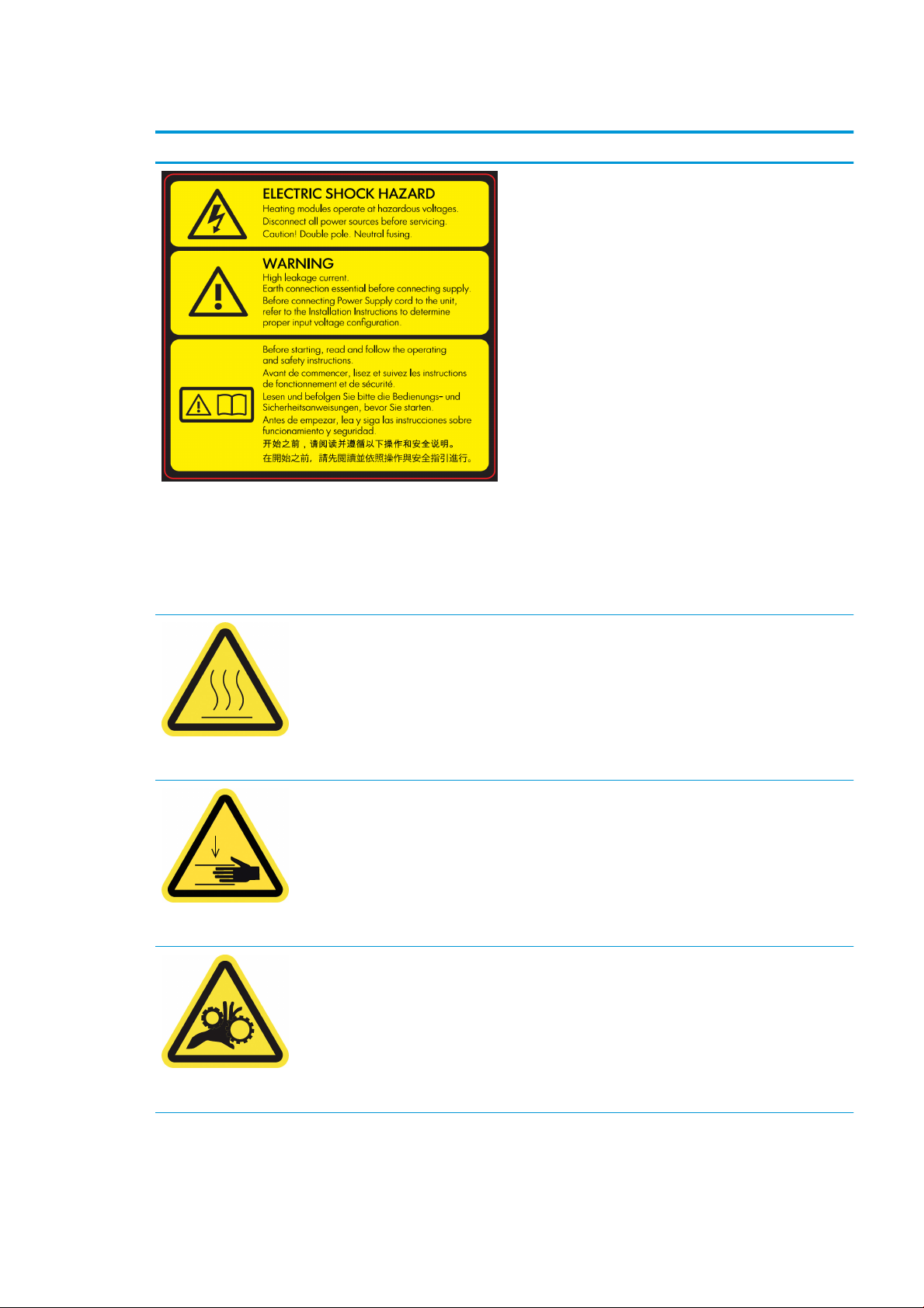
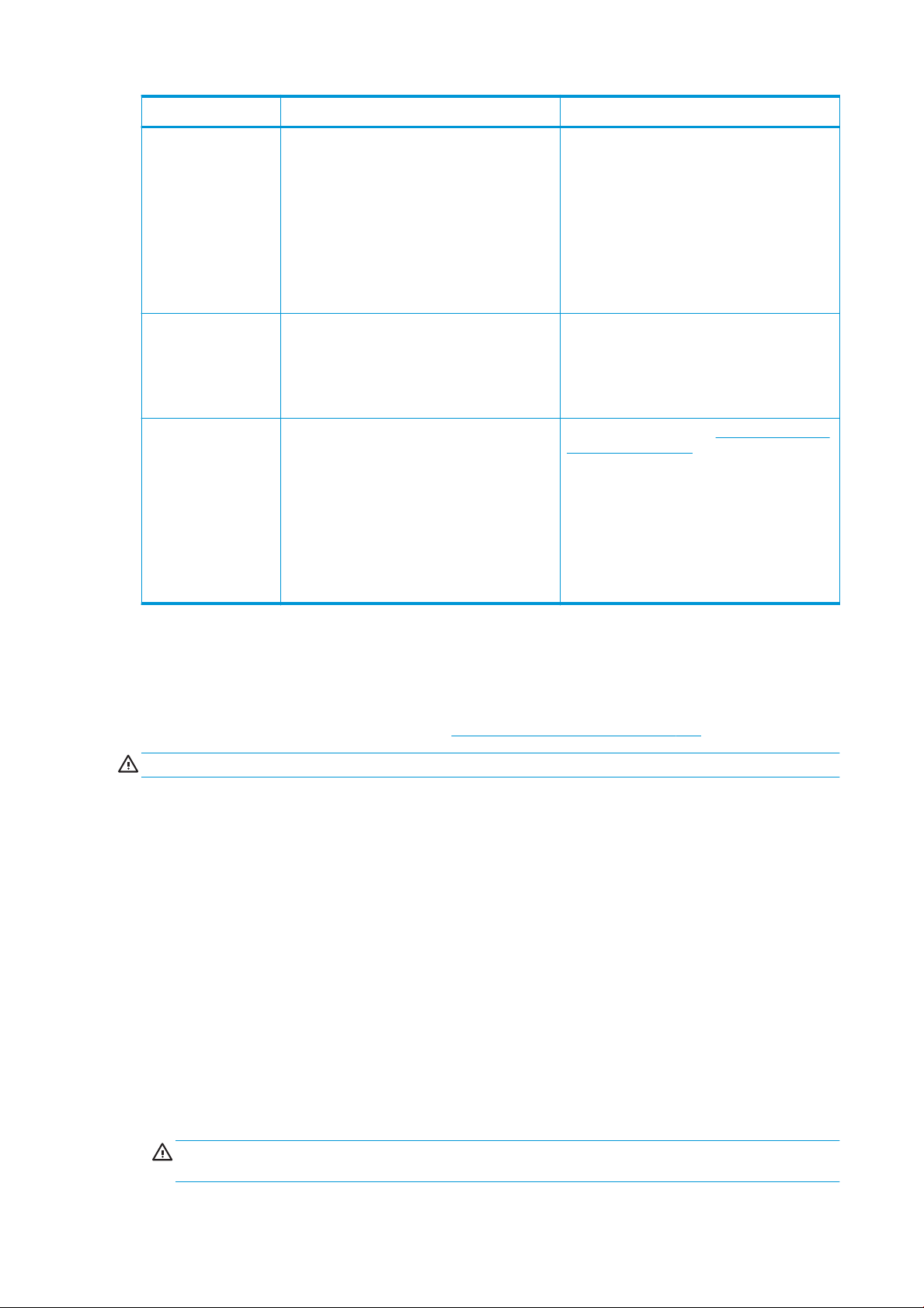
Warning labels
Label Explanation
Located on the e-cabinet; for service personnel only
Electric shock hazard
Heating modules operate at hazardous voltage. Disconnect
power source before servicing.
Caution! Double pole. Neutral fusing. Refer servicing to qualified
service personnel.
In case of operation of the fuse, parts of the printer that remain
energized may represent a hazard during servicing. Before
servicing, turn off the printer using the Branch Circuit Breakers
located in the building's Power Distribution Unit (PDU).
Warning
High leakage current. Current leakage may exceed 3.5 mA. Earth
connection essential before connecting supply. Equipment to be
connected to earthed mains only.
See installation instructions before connecting to the supply.
Ensure that the input voltage is within the printer's rated voltage
range. The printer requires up to two dedicated lines, each
protected by a branch circuit breaker according to site
preparation requirements.
Before starting
Located on the curing and drying modules
Located on each side of the substrate path, close to the PPS gear
Read and follow the operating and safety instructions before
starting the printer.
Risk of burns. Do not touch the internal enclosures of the printer's
drying and curing modules.
Crush hazard. Do not touch PPS while moving. When the
substrate has been loaded, the carriage descends into its printing
position, and could crush your hand or anything else left
underneath it.
Risk of trapped fingers. Do not touch gears while moving. Danger
that your hands may become trapped between gearwheels.
Located on each side of the substrate path, close to the PPS gear
ENWW Safety precautions 7
Page 14
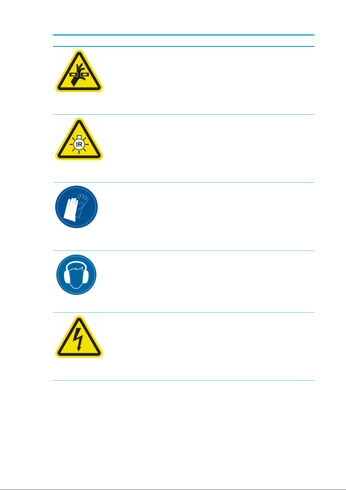
Label Explanation
Hazardous moving part. Keep away from moving printhead
carriage. When printing, the printhead carriage travels back and
forth across the substrate.
Located internally on the substrate path and internally on the
right cover; for maintenance/service personnel only
Light radiation hazard. Infrared (IR) radiation is emitted from this
printer. Do not modify the dryer enclosure. You are recommended
not to look directly at the lamps when they are on.
The dryer enclosure limits radiation in compliance with the
requirements of the exempt group of IEC 62471:2006,
Photobiological safety of lamps and lamp systems.
Located on the dryer module; for maintenance/service personnel
only
You are recommended to wear gloves when handling ink
cartridges, printhead cleaning cartridges, and the printhead
cleaning container.
Located on the condensation collector bottle and the printhead
cleaning roll carriage
Located at the rear, on the left cover
Located internally on heating modules and electrical cabinets; for
maintenance/service personnel only
Sound level could exceed 70 dBA in some print modes. Hearing
protection may be required.
Electric shock hazard. Disconnect power before servicing. Heating
modules and electrical cabinets operate at hazardous voltage.
8 Chapter 1 Introduction ENWW
Page 15
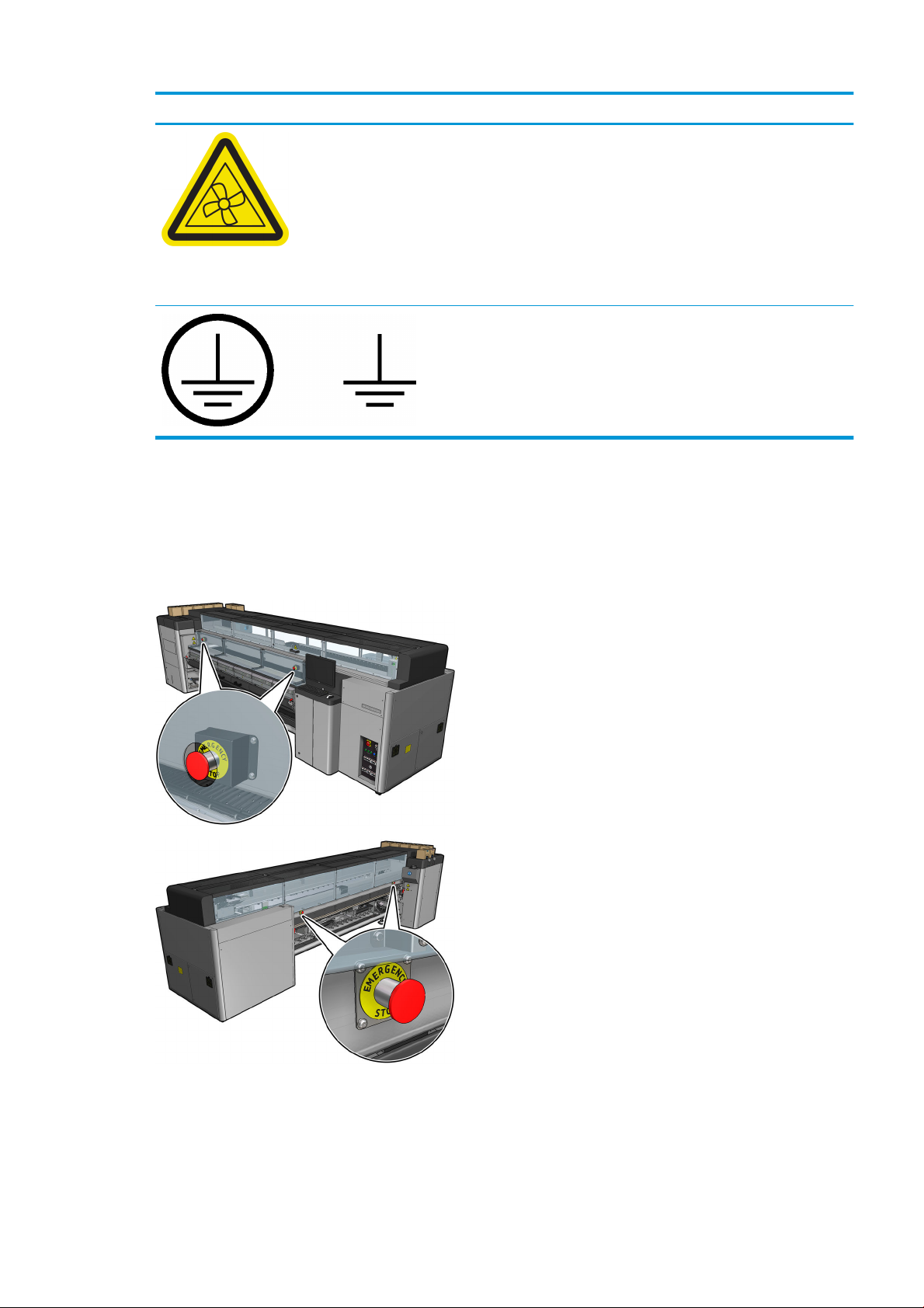
Label Explanation
Located internally, close to vacuum fan blades; for maintenance/
service personnel only
Emergency stop buttons
There are four emergency stop buttons distributed around the printer. If an emergency occurs, simply push
one of the emergency stop buttons to stop all printing processes. A system error message is displayed, and
the fans turn at maximum speed. Ensure that all emergency stop buttons are released before restarting the
printer.
Hazardous moving parts. Keep away from moving fan blades.
Identifies the Protective Earth (PE) terminal for qualified
electricians, and bonding terminals for maintenance/service
personnel only. Earth connection essential before connecting
supply.
For safety reasons, access to the print zone is not permitted while printing is in progress. Therefore, if the
front door or the loading table is opened, power to the carriage and to the drying and curing module is
disconnected. The print is cancelled and a system error may be displayed.
ENWW Safety precautions 9
Page 16
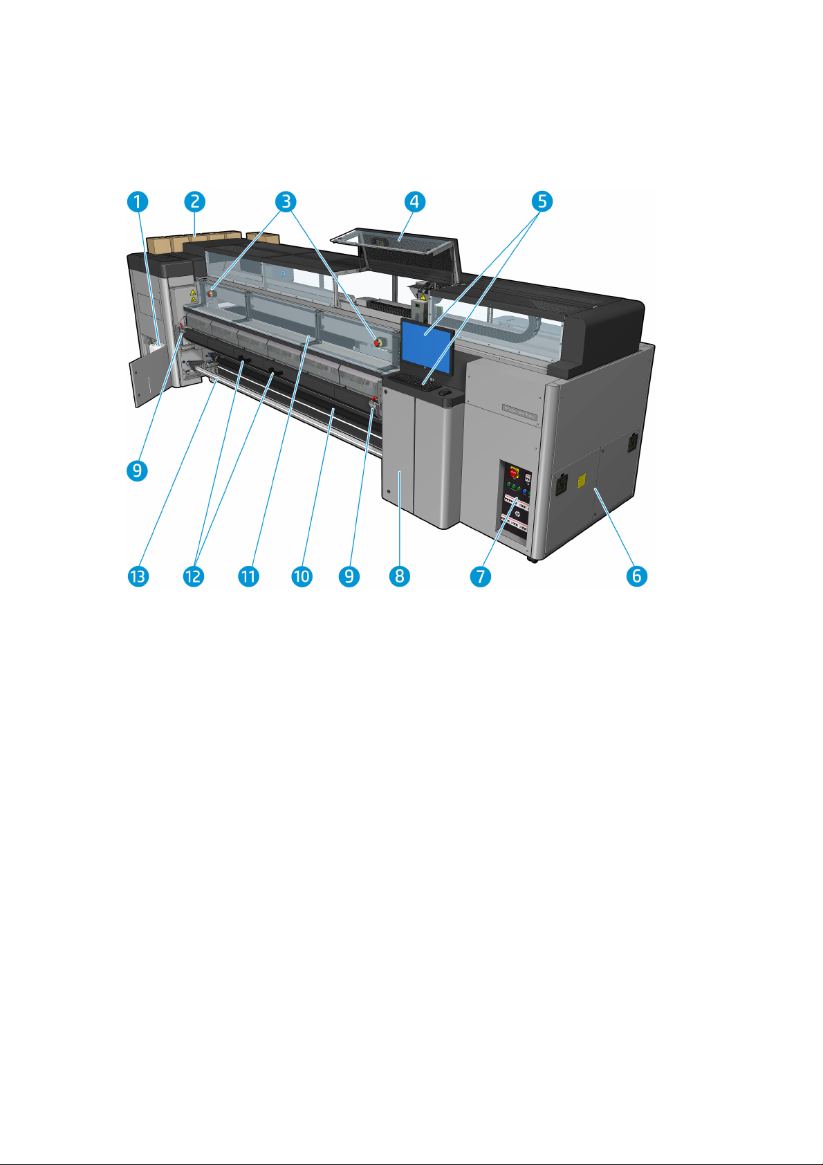
Main components
The following views of the printer illustrate the main components.
Front view
1. Condensation collector bottle
2. Ink cartridges
3. Emergency stop buttons
4. Service position window
5. Built-in computer
6. E-cabinet
7. Power switches, lights, and circuit breakers
8. Printhead cleaner roll door
9. Curing module latches, one on each side
10. Tension roller (for roll-to-free-fall configuration)
11. Front door
12. Curing module handles
13. Substrate output spindle
10 Chapter 1 Introduction ENWW
Page 17
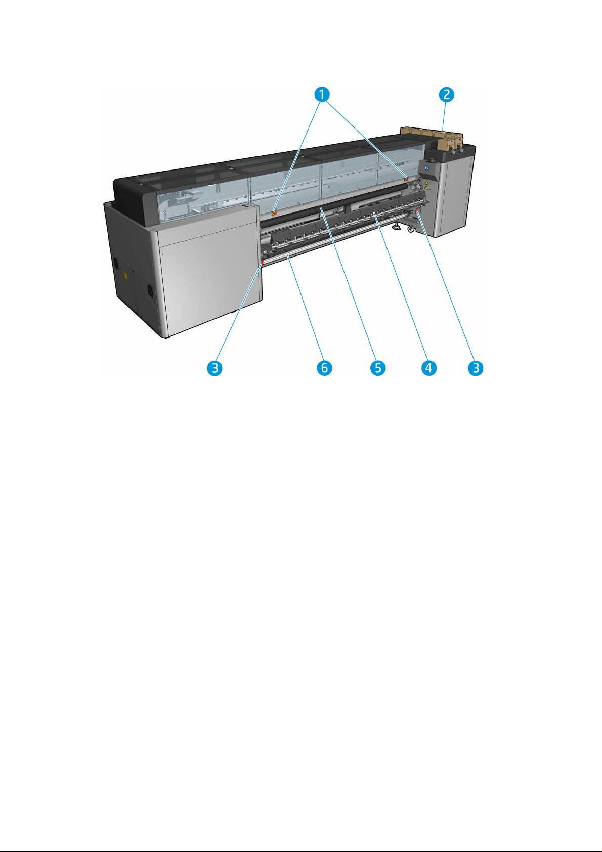
Rear view
1. Emergency stop buttons
2. Ink cartridges
3. Loading table latches, one on each side
4. Loading table
5. Drive roller
6. Substrate input spindle
ENWW Main components 11
Page 18
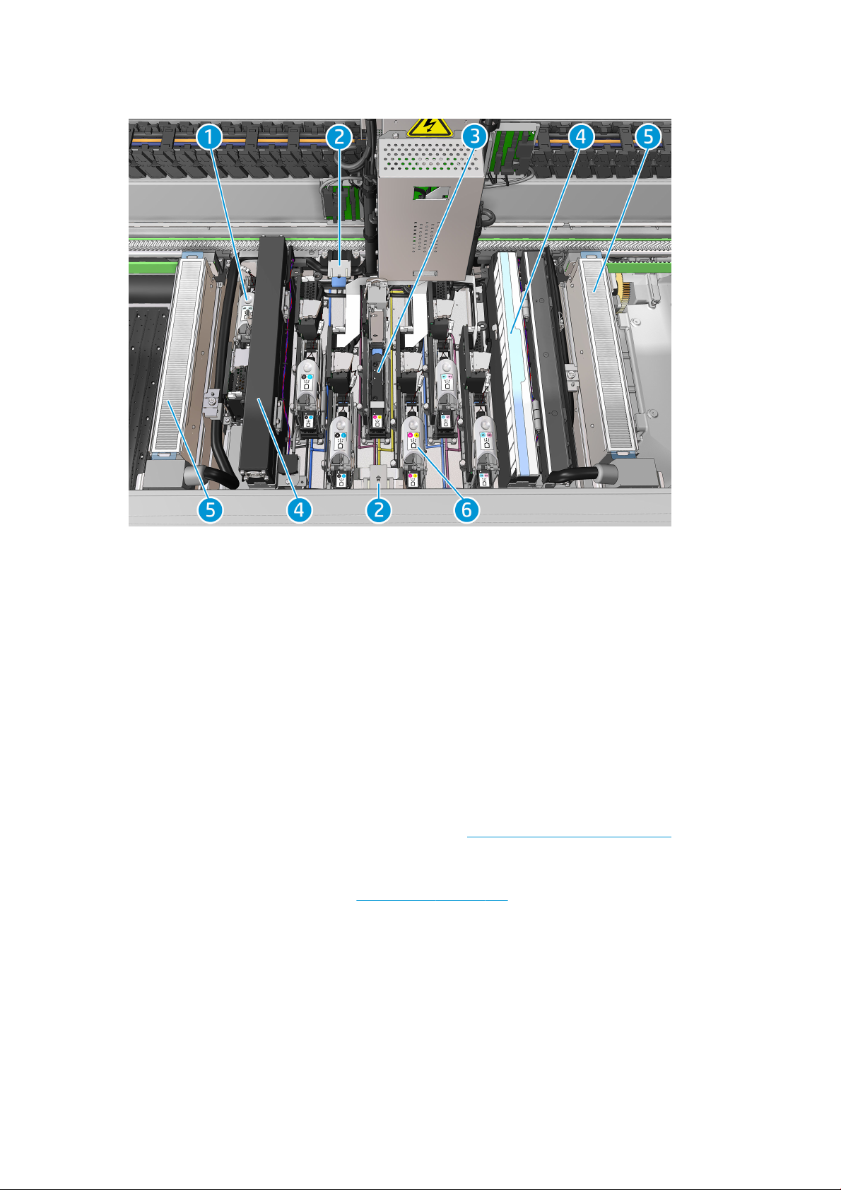
Carriage view
1. Optimizer printhead latch
2. Oiler foams
3. Printhead
4. Aerosol filters
5. Drying filters
6. Printhead latch
Printer software
Your printer requires the following software:
●
The HP Internal Print Server is provided with your printer and is already installed in the printer's built-in
computer. It displays printer alerts and a summary of printer status, manages print jobs, and must be
used to interact with the printer in various ways. See HP Internal Print Server on page 16.
●
The HP Print Care program is provided with your printer and is already installed in the printer's built-in
computer. It displays printer status and history in detail, and helps you to maintain the printer and solve
any problems that may arise. See HP Print Care on page 132.
●
A Raster Image Processor (RIP) should be run on a separate computer; it cannot be installed on the
printer's built-in computer. It is not provided with the printer and should be obtained separately.
12 Chapter 1 Introduction ENWW
Page 19
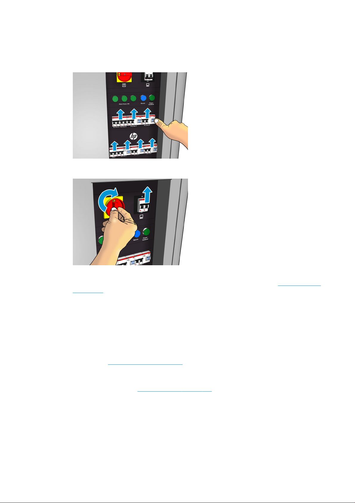
Turn on the printer for the first time
1. Make sure that the two bottom rows of circuit breakers at the front right of the printer are all in the up
position.
2. Turn the main switch to the on position, and also turn on the PC switch beside it.
3. Check that all three green lights are on. In normal operation these lights should always be on. If any of
them are off, check the Internal Print Server in case there is a system error, and see Printer messages
on page 298 or check with your electrician.
4. Wait for the Internal Print Server to tell you that the printer is waiting for rearm.
5. Perform a visual check of the printer.
6. Press the blue rearm button at the front right of the printer. This enables all of the printer's high-power
subsystems.
7. Check that the printer-enabled green light turns on. In normal operation this light should always be on.
If at any time you notice that this light is off, check the Internal Print Server in case there is a system
error, and see Printer messages on page 298.
8. Wait for the Internal Print Server to indicate that the printer is ready. This can take several minutes.
When initialization is complete, the Internal Print Server displays a Ready message. If a system error
message is displayed, see Printer messages on page 298.
Turn the printer on and off
The printer has three power-off levels. Each of them goes deeper, until you reach complete shutdown at
level 3.
ENWW Turn on the printer for the first time 13
Page 20
Level Turn off Turn on
1: Major power
electronics and engine
off.
2: All printer systems off
(recommended).
3: All printer systems
and Internal Print Server
off.
Wait for the Internal Print Server to indicate that
the printer is ready, then turn off the high-power
subsystems by pressing the shutdown icon near the
top left corner of the screen. Wait until the Internal
Print Server reports that it has lost its connection to
the printer.
NOTE: After the printer electronics have been
turned off at the Internal Print Server, the fans turn
at maximum speed for safety reasons. This is
normal behavior and not a cause for concern.
After completing level 1, turn off the main switch.
The fans should stop.
After completing level 2, shut down the Internal
Print Server from the Windows Start button, and
wait until you see a black screen with the message
No input signal.
CAUTION: The computer may be damaged if it is
turned off incorrectly.
Once the Internal Print Server is completely off and
you see No input signal on the screen, turn off the
computer power switch.
Click the Wake Up button up in the top left corner of
the Internal Print Server window, and wait for the
printer to turn on the high-power systems.
When prompted, press the blue rearm button at the
front right of the printer.
After completing level 1, turn on the main switch,
and ensure that the circuit breaker beside it is on.
When prompted, press the blue rearm button and
wait for the Internal Print Server to announce that
the printer is Ready.
After completing level 2, see Turn on the printer for
the first time on page 13.
Move the printer
If you wish to move the printer a short distance on the same site, across a horizontal floor with no steps and
no slopes of more than 5% inclination, see the following instructions. For more difficult movement
operations, call your service representative (see HP Customer Care Centers on page 292).
CAUTION: Slopes steeper than 5% may cause serious damage to the printer.
1. Turn off the printer.
2. Disconnect all power and network cables from the printer.
3. Disconnect all ink cartridges and remove them from the printer. Hold the cartridge connectors in
position with adhesive tape.
4. Raise the feet so that the wheels (A) touch the ground. To raise a foot:
a. Use a 30 mm (1.18 in) wrench to unlock the nut at the top of the foot.
b. Rotate the nut manually down the bolt. Leave about 2 cm (0.8 in) clearance at the bottom between
nut and foot.
c. Use a 15 mm (0.59 in) wrench to rotate the foot upwards. Use the flat faces at the bottom of the
bolt to fit the wrench.
d. Raise the foot as far as the bolt allows.
e. Use the 30 mm (1.18 in) wrench to relock the nut.
CAUTION: Take care to raise the feet as high as you can. They may break if they touch the ground
while the printer is in motion.
14 Chapter 1 Introduction ENWW
Page 21

5. Push the printer from the outside corners of the top covers. Remember to avoid slopes steeper than
5%.
After moving the printer, you may in some cases need an electrician to reconnect the power cables. You may
also need to reconfigure the network, from the printer's built-in computer and from the RIP computer. See
the Installation Guide for more details, including the minimum space required around the printer.
ENWW Move the printer 15
Page 22
2 HP Internal Print Server
Start the Internal Print Server
The Internal Print Server starts automatically with Windows, and runs continually, in the background if not in
the foreground.
If for some reason it has stopped running, or its window is not visible, you can start it from the Windows Start
menu or by double-clicking its icon on the desktop.
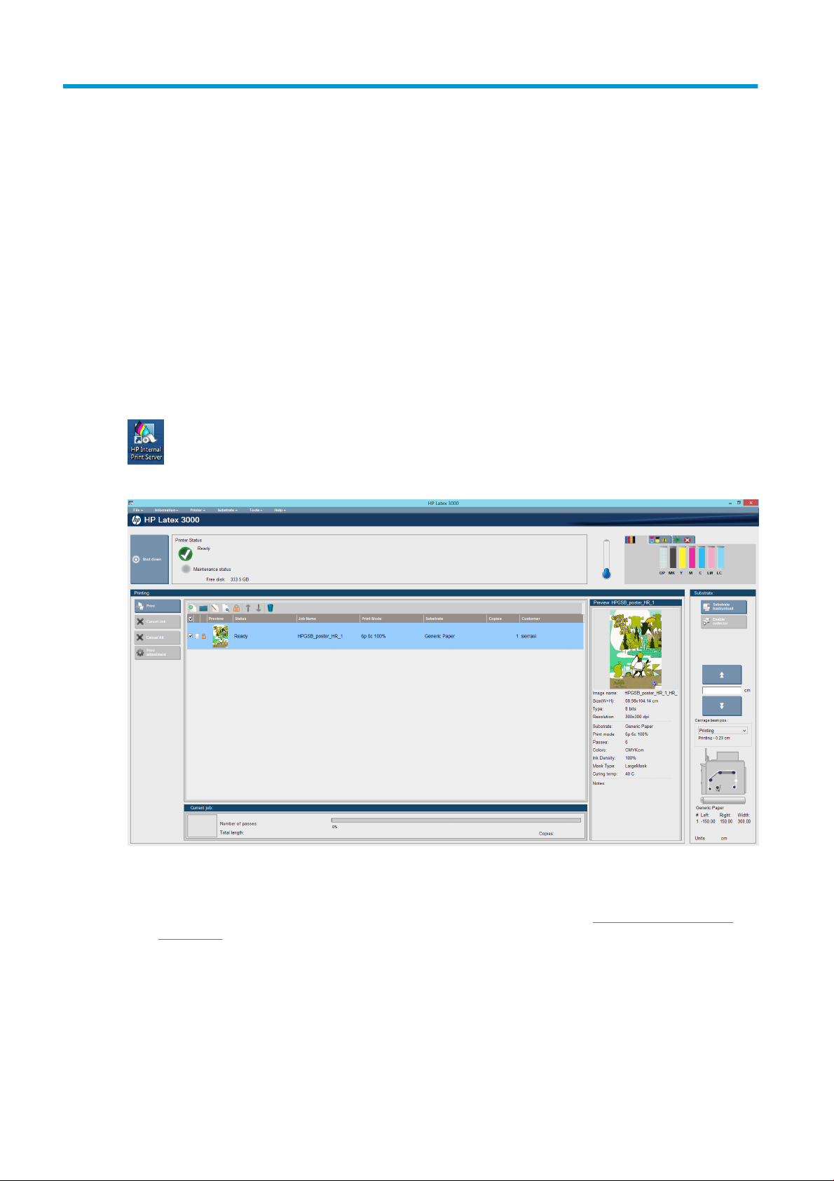
When it starts, the main screen appears.
In the main screen:
●
You can shut down the printer by pressing the Shut down button at the top left.
●
The top central pane shows the printer status and maintenance status. See Printer status and alerts
on page 20.
●
The thermometer to the right of the status pane shows the curing temperature.
●
To the right of the thermometer, you can see a summary of the status of the ink cartridges, the
printheads, and the printhead cleaning roll.
●
The Printing pane occupies most of the window, and includes:
16 Chapter 2 HP Internal Print Server ENWW
Page 23

◦
The Print, Cancel, and Print adjustment buttons
◦
The job queue
◦
The print preview and job settings
●
The Substrate pane includes the Substrate load/unload, Enable collector, and move carriage beam
buttons; and information about how the current substrate is loaded.
Change the language of the Internal Print Server
When the Internal Print Server starts, it uses the language selected in the Windows Regional and Language
Options. To change the selected language:
1. Open the Control Panel from the start menu.
2. If you are using the Category View of the Control Panel, open the Clock, Language, and Region
category.
3. Open the Regional and Language Options.
4. In the Formats tab, change the current format to correspond with the language you want.
5. Press the OK button.
The change takes effect when Windows is restarted.
Change the units of measurement in the Internal Print Server
To change the units of measurement in the Internal Print Server, select the Tools > Preferences > Units. You
can change the units of length and temperature.
Set the Internal Print Server preferences
To change the Internal Print Server's preferences, select Preferences from the Tools menu. In the
Preferences window, you will see four tabs.
General tab
●
Units of length and temperature
●
Remarks (to add as a footer to the printed file)
ENWW Change the language of the Internal Print Server 17
Page 24
●
Font of footer text
●
Hot folder
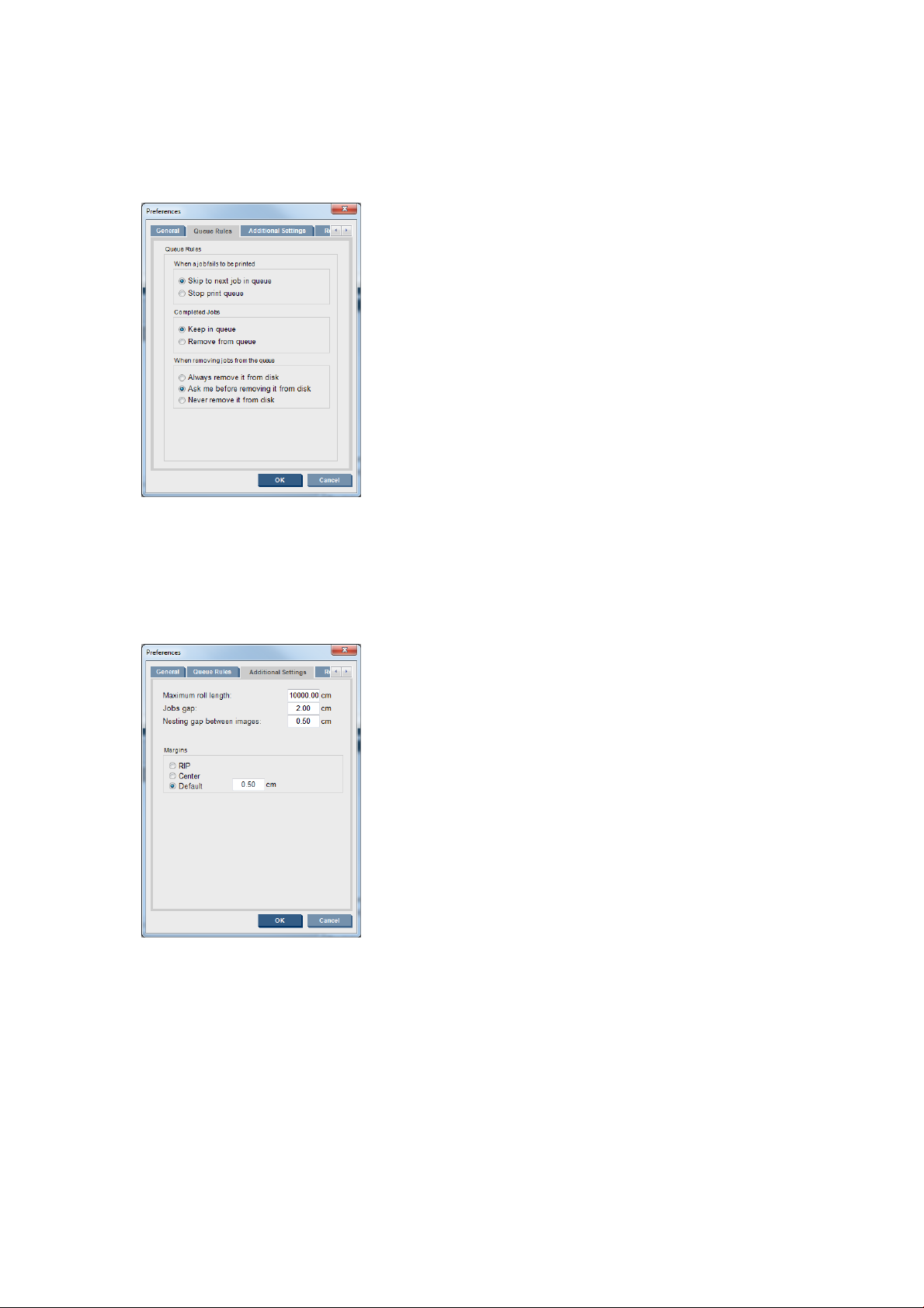
Queue Rules tab
●
Action when job fails
●
Action when job has been printed
●
Action when job is removed from the queue
Additional Settings tab
●
Maximum roll length
●
Gap between jobs
●
Nesting gap between images
●
Margins:
◦
RIP: Margins are set as defined in the RIP.
◦
Center: The image is horizontally centered on the loaded substrate.
◦
Default: The default margins are set to 5.0 mm (0.02 in). You can define the default left margin in
the Job Properties window.
18 Chapter 2 HP Internal Print Server ENWW
Page 25
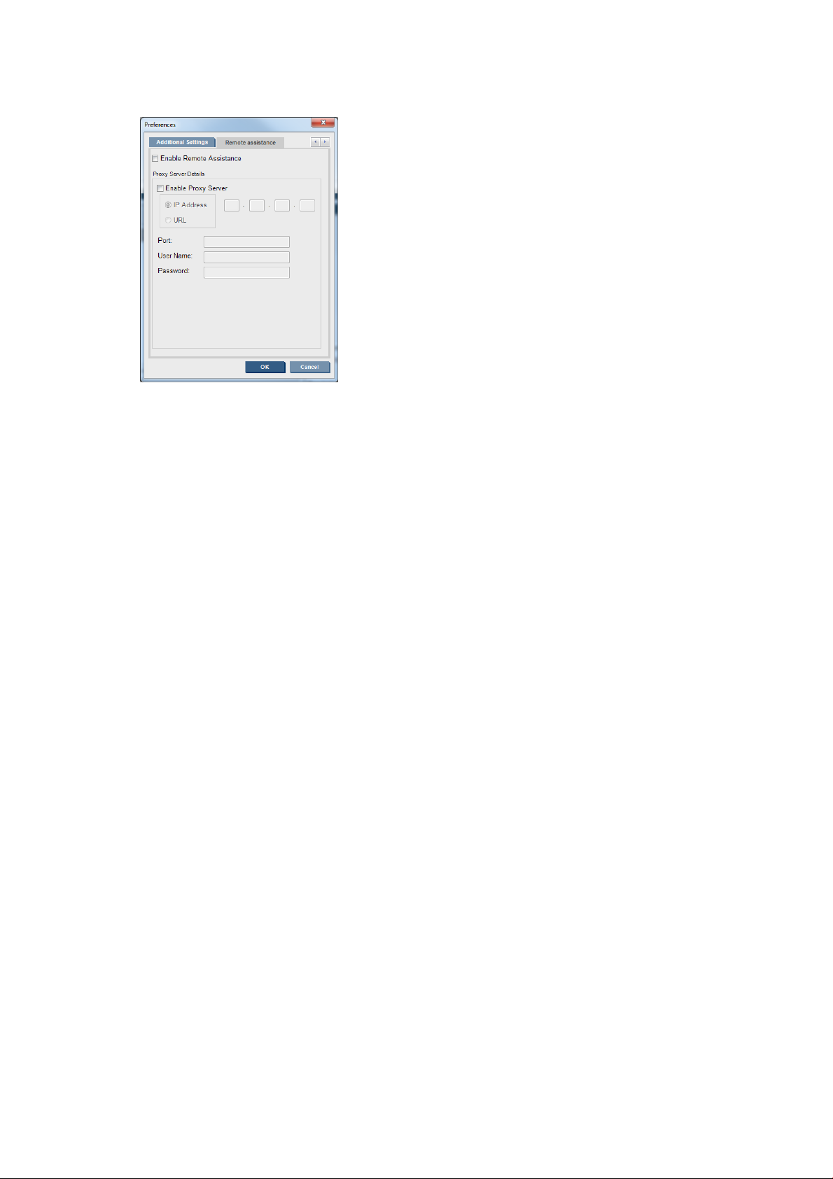
Remote Assistance tab
●
Enable remote assistance
●
Enable proxy server and give details
Internal Print Server menus
The Internal Print Server provides the following menus.
The File menu
●
Add New Job
●
Add Existing Job
●
Edit Job
●
Delete Job
●
Exit
The Substrate menu
●
Load/Unload
●
Settings
●
Create
●
Edit
●
Clone
The Information menu
●
Alerts
●
Supplies
●
Service information
The Tools menu
●
Preferences
●
HP Scitex Print Care
●
HP Proactive Support
●
Firmware update
●
Wake up
The Printer menu
●
Printing adjustments
●
Printhead alignment
●
Printhead cleaning
●
Replace printheads
●
Replace cleaning roll kit
●
Advance calibration
●
Enable/Disable collector
The Help menu
●
About
●
User's guide
●
Rename
●
Remove
●
Color calibration
●
Presets management
●
Find new presets
●
Shut down
●
Reinitialize carriage
ENWW Internal Print Server menus 19
Page 26

Printer status and alerts
The Internal Print Server displays the general status of the printer, the maintenance status, the loaded
substrate, and the ink system.
The printer can communicate the following types of alerts:
Printer status
●
Errors: When the printer is unable to print.
●
Warnings: When the printer needs attention for an adjustment, such as a calibration, preventive
maintenance or ink cartridge replacement.
A summary list of printer alerts appears in the main window of the Internal Print Server. To display a more
complete and detailed list, select Information > Alerts.
For more information about a particular alert, see Printer messages on page 298.
Maintenance status
●
Green light: No maintenance is needed.
●
Yellow light: Maintenance procedure date is approaching. Press the yellow button to check Print Care
for details. See HP Print Care on page 132.
●
Orange light: Maintenance is required. Press the orange button to check Print Care for details.
●
Red light: Maintenance is required urgently. Press the red button to check Print Care for details.
●
Grayed out: Print Care is not running. Press the orange button.
Update the firmware and the Internal Print Server
TIP: When updating the firmware and the Internal Print Server, first update the firmware and then the
Internal Print Server.
Update the firmware
From time to time firmware updates will be available from Hewlett-Packard. These updates increase the
printer's functionality and enhance its features.
Firmware updates can be downloaded from the Internet and installed in your printer using the Internal Print
Server: select Firmware update from the Tools menu.
20 Chapter 2 HP Internal Print Server ENWW
Page 27

Follow the instructions on your screen to download the firmware file and store it on your hard disk. Then
select the downloaded file and click Update.
The firmware includes a set of the most commonly used substrate presets. Extra substrate presets can be
downloaded separately; see Substrate presets on page 67.
Update the Internal Print Server
IMPORTANT: Remove the previous version of the Internal Print Server in the printer's built-in computer
before installing the new version.
1. Remove the current version of the Internal Print Server through the control panel. Select Uninstall
Internal Print Server Application (this deletes any current job in the queue, but not ripped files).
2. Download the file to the built-in computer's hard disk (but not to the desktop).
3. Unzip/extract the files HPIPS.msi and Setup.exe.
4. Run the file Setup.exe and follow the onscreen instructions until the new software is installed.
Maintain the Internal Print Server
The Internal Print Server runs under Microsoft Windows on the computer supplied with the printer. In that
operating environment, there are various things you can check in order to maintain optimum performance.
You can make these checks after restarting the computer and before starting the Internal Print Server.
●
The user account should be a Standard account and not an Administrator account.
●
No software should be installed on the computer except the software initially provided by HP (which
includes antivirus software).
●
Free space on the hard disk should be at least 10 GB.
●
In the Control Panel, Hardware and Sound > Power Options, the high-performance power plan should
be selected and sleep mode disabled.
●
Turn off User Account Control from the User Accounts icon in the Windows Control Panel.
●
User a blank screen saver.
●
Press the start button and right-click Computer. Select Manage > Device Manager > Disk drives. Rightclick the hard disk, and select Properties > Policies. Ensure that Optimize for performance, Enable
write caching on the disk and Enable advanced performance are all enabled.
●
Ensure that scheduled defragmentation is enabled. Press the start button and right-click Computer.
Select Manage > Disk Management. Right-click the hard disk, and select Properties > Tools >
Defragment Now, and ensure that Run on a schedule is enabled.
●
In the Control Panel, select System > Advanced system settings > Advanced > Performance > Visual
Effects > Custom. Ensure that all effects are disabled except Enable Desktop composition, Enable
transparent glass, Smooth edges of screen fonts and Use visual styles on windows and buttons.
●
Open Internet Explorer and select Tools > Internet options > Connections > LAN settings. If a proxy
server is used, ensure that Bypass proxy server for local addresses is enabled.
●
Ensure that the computer is connected to the Internet and use Windows Update to ensure that all
available updates (including Windows Service Packs) have been installed successfully.
●
Start the Internal Print Server, and use File > Delete job to delete any jobs for which there is no further
use.
ENWW Maintain the Internal Print Server 21
Page 28

3 Handle the substrate
Supported substrate types
The following substrate types are compatible with your printer. For specific substrate settings and profiles,
see the online HP Media Locator: http://www.hp.com/go/mediasolutionslocator.
NOTE: Porous substrates and substrates with porous liners are supported only when using the ink collector
kit (see The ink collector kit on page 32).
Self-adhesive vinyl
●
Cast self-adhesive vinyl
●
Calendered self-adhesive vinyl
●
Perforated self-adhesive vinyl
PVC banner
Paper
●
Transparent self-adhesive vinyl
●
Reflective self-adhesive vinyl
●
Frontlit banner
●
Backlit banner
●
Scrim banner
●
Scrimless banner
●
Mesh banner with liner
●
Blockout banner
●
Truck curtain banner or tarpaulin
●
Coated paper
●
Uncoated paper
●
Photo paper
●
Photorealistic paper
●
Blue-back paper
●
Self-adhesive paper
22 Chapter 3 Handle the substrate ENWW
Page 29

PP and PE film and banner
●
Polypropylene (PP) film
●
Synthetic paper (such as Yupo)
●
Tyvek
●
Coated PE/HDPE (polyethylene) banner
PET film
●
Polyester (PET) backlit film
●
Polyester (PET) frontlit film
●
Polyester (PET) grey-back film
Textile
Porous textiles may be used only with the ink collector. To check the porosity of your substrate, see Check
the porosity of your substrate on page 23.
●
Polyester textile and fabric
●
Textile banner
●
Backdrops
●
●
●
●
●
●
●
Wall covering
NOTE: This is an application example, not a selectable category.
●
●
●
●
●
Textile mesh with liner
Frontlit textile with liner if porous
Backlit textile with liner if porous
Canvas
Flag and voile with liner
Cotton textile
Self-adhesive textile
Paper wall covering or wallpaper
PVC wall covering
Pre-pasted wall covering
Non-woven wall covering
Textile wall covering
●
Self-adhesive wall covering
Check the porosity of your substrate
1. If the printer has any substrate loaded, unload it.
2. Cut a piece of self-adhesive vinyl white gloss 15 × 50 mm (0.6 × 2 in) in size.
ENWW Supported substrate types 23
Page 30

3. Stick it to the platen, covering the substrate-advance sensor.
4. Load the substrate that you want to check.
5. Open your RIP software.
6. Obtain the test file from the printer’s built-in computer: C:\Users\hplatex\Documents\HP IPS
\InkTrespassingCheck\Ink_trespassing_check.pdf.
7. Print the test file using the number of passes and substrate preset that you intend to use in future with
this substrate (or a similar profile in terms of ink limit).
8. Unload the substrate.
9. Remove the strip of self-adhesive vinyl from the platen.
10. Look at the self-adhesive vinyl you have taken from the platen.
●
If the strip is completely white (has no ink on it), the tested substrate is non-porous and may be
used for printing as described in this guide.
●
If the strip is non-white, the tested substrate is porous and may be used only with the ink collector
installed.
11. Clean the print zone, see Clean the print zone on page 149.
Supported HP substrates
Category Substrate Color
Self-adhesive
vinyl
PVC banners HP Durable Frontlit Scrim Banner
HP Air Release Adhesive Gloss Cast Vinyl
Without liner: 50 microns (2 mil) • 100 g/m² • 45,7 m (150 ft)
With liner: 241 microns (9.5 mil) • 260 g/m² • 45,7 m (150 ft)
HP Permanent Gloss Adhesive Vinyl
Without liner: 88 microns (3.5 mil) • 145 g/m² • 45,7 m (150 ft)/ 91,4 m (300 ft)
With liner: 238 microns (9.4 mil) • 270 g/m² • 45,7 m (150 ft)/ 91,4 m (300 ft)
HP Permanent Matte Adhesive Vinyl
Without liner: 88 microns (3.5 mil) • 145 g/m² • 45,7 m (150 ft)/ 91,4 m (300 ft)
With liner: 238 microns (9.4 mil) • 270 g/m² • 45,7 m (150 ft)/ 91,4 m (300 ft)
HP One-View Perforated Adhesive Window Vinyl
Without liner: 165 microns (6.5 mil) • 155 g/m² • 50 m (164 ft)
With liner: 406 microns (16 mil) • 288 g/m² • 50 m (164 ft)
449 microns (17.7 mil) • 535 g/m² • 35 m (115 ft)
Applications
calib.
Yes Vehicle wraps,
car/bus/track fleets,
signs
Yes
Yes
No
Yes Banners, POP, flags,
track covers, wall
murals
Paper HP PVC-Free Wall Paper *
177 microns (7 mil) • 175 g/m² • 30,5 m (100 ft)
HP White Satin Poster Paper
165 microns (6.5 mil) • 136 g/m² • 61 m (200 ft)
Yes POP indoor and
outdoor, windows, bus
shelters, billboards,
wall decorations
24 Chapter 3 Handle the substrate ENWW
Page 31

Category Substrate Color
calib.
Applications
PP and PE film
and banners
HP Photo-realistic Poster Paper
205 microns (8.1 mil) • 205 g/m² • 61 m (200 ft)
HP Blue Back Billboard Paper
165 microns (6.5 mil) • 123 g/m² • 80 m (262 ft)
New HP Universal Coated Paper, 3 in core
124 microns (4.9 mil) • 90 g/m² • 61 m (200 ft)
New HP Coated Paper, 3 in core
114 microns (4.5 mil) • 90 g/m² • 61 m (200 ft)
New HP Universal Heavyweight Coated Paper, 3 in core
165 microns (6.5 mil) • 125 g/m² • 61 m (200 ft)
New HP Heavyweight Coated Paper, 3 in core
167 microns (6.6 mil) • 130 g/m² • 61 m (200 ft)
New HP Super Heavyweight Plus Matte Paper, 3 in core
259 microns (10.2 mil) • 210 g/m² • 61 m (200 ft)
New HP HDPE Reinforced Banner
203 microns (8 mil) • 170 g/m² • 45,7 m (150 ft)
New HP Everyday Matte Polypropylene, 3 in core
Yes
Yes
Yes
Yes
Yes
Yes
Yes
Yes Banners, POP, flags,
track covers, wall
murals, large
photographs, floor
Yes
covering
PET film
Textile
203 microns (8 mil) • 120 g/m² • 61 m (200 ft)
New HP Everyday Adhesive Matte Polypropylene, 3 in core
Without liner: 180 microns (7.1 mil) • 120 g/m² • 30,5 m (100 ft)
With liner: 215 microns (8.5 mil) • 168 g/m² • 30,5 m (100 ft)
HP DuPont Tyvek Banner
HP Backlit Polyester Film
304 microns (12 mil) • 135 g/m² • 30,5 m (100 ft)
HP Light Textile Display Banner
381 microns (15 mil) • 210 g/m² • 50 m (164 ft)
HP Heavy Textile Banner
381 microns (15 mil) • 210 g/m² • 50 m (164 ft)
HP Satin Canvas
419 microns (16.5 mil) • 370 g/m² • 14,9 m (49 ft)
Yes
No
Yes Bus shelters, airport
ads, POP, street ads
No Indoor flags, wall
murals, interior
decoration, fine arts
No
No
ENWW Supported HP substrates 25
Page 32

●
For third-party substrate solutions with ColorPRO technology, see http://ColorPROtechnology.com/.
●
HP PVC-free Wall Paper imprimé avec les encres HP Latex est classé A+ selon l’arrêté du 19 avril 2011
«Émissions dans l'air intérieur», qui définit des seuils sur l’émission de polluants volatils posant des
problèmes en cas d’inhalation – sur une échelle de A+ (émission très basses) à C (émission élevée).
●
HP PVC-free Wall Paper printed with HP Latex Inks is rated A+ according to Émissions dans l'air intérieur,
which provides a statement of the level of emission of volatile substances in indoor air posing health
risks if inhaled—on a scale from A+ (very low emission) to C (high emission).
* HP PVC-Free Wall Paper printed with HP Latex Inks is GREENGUARD Children & Schools Certified. See
http://www.greenguard.org/.
* HP PVC-Free Wall Paper printed with HP Latex Inks meets AgBB criteria for health-related evaluation of VOC
emissions of indoor building products. Seehttp://www.umweltbundesamt.de/produkte-e/bauprodukte/
agbb.htm.
HP large-format substrate take-back program availability varies. Some recyclable HP substrates can be
recycled through commonly available recycling programs. Recycling programs may not exist in your area.
See
http://www.hp.com/recycle/ for details.
Substrate tips
Maintain the substrates
Keep substrates in their sealed wrapping material while they are in storage, and store rolls vertically to avoid
the migration of plasticizers in some materials.
Move substrates from the storage area to the print production area at least 24 hours before use, so that they
can adapt to its temperature and humidity.
General tips
Handle unprinted and printed substrates with care, and preferably with cotton gloves, to avoid fingerprints.
For heavy rolls, use a forklift, and two people wearing security shoes.
Before loading a roll:
●
Check that temperature and humidity in the room are within the recommended ranges for the printer.
See Environmental specifications on page 296.
●
Check that neither the roll nor its core are bent or deformed, which may cause the substrate to jam in
the printer.
●
If the roll has been stored in a place not offering the recommended environmental conditions, allow
some time for it to adapt to the temperature and humidity of the printer's environment.
●
Check which is the correct side for printing, by reading the label inside the core or the note inserted into
the package.
●
Check that the substrate is correctly attached to the input core. Otherwise, the Internal Print Server will
report an error.
●
Check the substrate thickness.
26 Chapter 3 Handle the substrate ENWW
Page 33

◦
Up to 0.4 mm (0.016 in): Print normally.
◦
0.4 to 2 mm (0.016 to 0.079 in): Raise the carriage beam to a custom position. Edge holders are
not needed and should not be used.
◦
More than 2 mm (0.079 in): Not supported.
While loading a roll, ensure that the leading edge is parallel and straight across the output core, and attached
evenly (start taping the substrate to the core at the center, then move towards the edges).
Also ensure that the side edges of the input and output roll are properly aligned. An incorrectly loaded roll
may cause waves or cockles in the substrate, leading to ink smearing and printhead crashes.
After you have loaded a roll:
●
If you intend to use substrate edge holders, do not use edge holders from another printer, use only the
edge holders that came with your printer.
●
Check the correct carriage beam position for printing: customized position for thick substrates, printing
position for others. See Set the carriage beam position on page 75.
●
Check that you are using the correct substrate preset in the Internal Print Server and the correct ICC
profile and other settings in the RIP.
●
HP substrates are optimized to provide the best out-of-the-box printing experience with your printer.
●
Use the Internal Print Server to check that any calibrations appropriate for your substrate have been
done: printhead alignment, color calibration. See Printer calibration on page 119.
●
Do not cut off pieces of substrate while the substrate is loaded into the printer. This may cause the
remaining substrate to jam.
You can find further information on the Web:
●
The specifications, finishing, processing, and warranty information for each individual HP substrate are
available from http://www.globalBMG.com/hp/signagemedia and http://www.globalBMG.com/hp/
HPMediaWarranties.
●
HP Image Permanence information is available from http://www.globalBMG.com/hp/printpermanence.
●
HP offers to recycle some substrates through the HP Take-Back Program, such as HP HDPE Reinforced
Banner, HP Light Textile Display Banner, HP Heavy Textile Banner, HP Everyday Matte Polypropylene, 3in Core, and HP DuPont Tyvek Banner. Recycling opportunities for these products may not exist in all
areas. You should consult local recycling resources about recycling these products. For recycling in the
USA, see the HP recycling services site, http://www.hp.com/go/recycleLFmedia/.
HP offers to recycle some other substrates through the standard paper recycling process, such as HP
White Satin Poster Paper, HP Photo-realistic Poster Paper, HP Coated Paper (3-in core), HP Universal
Coated Paper (3-in core), HP Universal Heavyweight Coated Paper (3-in core), HP Heavyweight Coated
Paper (3-in core), and HP Super Heavyweight Plus Matte Paper (3-in core).
Color consistency
Your printer has been designed to provide an excellent experience in terms of color consistency and
repeatability. This allows large jobs such as fleet graphics and wall coverings to be printed in tiles or panels,
with confidence that, when the finished panels are placed edge to edge, the colors will match at the joins.
The color variation within a printed job has been measured to be within this limit:
Maximum color difference (95% of colors) <= 2 dE 2000
ENWW Substrate tips 27
Page 34

NOTE: This is based on reflective measurements on a 943 color target under CIE standard illuminant D50,
and according to the standard CIEDE 2000 as per CIE Draft Standard DS 014-6/E:2012. 5% of colors may
experience variations above 2 dE 2000. Backlit substrates measured in transmission mode may yield
different results.
Color matching is dependent on many external factors. Take the following points into account to achieve this
level of consistency:
●
If a large job is being printed in panels, more than one roll may be required. All rolls should be from the
same batch, and stored under correct conditions according to the manufacturer’s specifications.
●
Operating conditions (temperature and humidity) should be kept constant during the printing of the
entire job.
●
Ensure that a printhead check and clean routine has been run prior to starting the job. If any printhead
changes are required during the job, printhead alignment and color calibration should be done.
See also Color calibration on page 125.
Substrate configurations
The substrate can be loaded in a variety of different configurations to suit your different needs. Before
loading, you must go to the Internal Print Server and select Substrate load/unload, then select the
configuration you intend to use.
The basic configurations are illustrated below. These configurations can be used for single-roll or dual-roll
printing.
●
The roll-to-roll configuration is suitable when you do not intend to cut and take away some prints or
the output roll in the middle of a print job being done using a particular input roll. The substrate cannot
be cut in mid-roll, except during double-sided printing, and then it must be reloaded afterwards.
28 Chapter 3 Handle the substrate ENWW
Page 35

●
The roll-to-free-fall configuration is suitable when you want to cut and remove one or more prints as
soon as they come out of the printer. The substrate is kept under tension between the input roll and the
tension roller; but it can be cut after the tension roller because then it is no longer under tension.
●
The roll-to-collector configuration is suitable when you may want to cut the substrate and remove the
output roll before finishing the print job being done using a particular input roll. The substrate is kept
under tension between the input roll and the tension roller; but it can be cut after the tension roller
because then it is no longer under tension.
Prepare to print
The following steps must be followed before the printer can print:
1. Go to the Internal Print Server and select Substrate Load/Unload to open the Printer Configuration
window.
2. Select the printer configuration that you intend to use; the on-screen help will appear on the left.
NOTE: The Skip Substrate load check box should be checked only if the printer has just previously
had the same configuration (i.e. the same substrate, same profile), and because of a severe system
error, you had to restart the printer.
3. Load the substrate. Substrate loading instructions are displayed in the Internal Print Server window. For
more detailed instructions, see Load a roll onto the spindle on page 43 and Load a roll into the printer
on page 45.
ENWW Prepare to print 29
Page 36

4. Select the substrate type.
5. Press the Finish button in the Internal Print Server to start the substrate check, then enter the substrate
type in the Loaded Substrate window.
TIP: If the printer has been idle overnight with substrate loaded, and exposed to high or low temperatures,
advance the substrate 13 to 25 cm (5 to 10 in) before printing, to avoid printhead crashes or ink smears on
the substrate.
The substrate edge holders
The purpose of the substrate edge holders is to prevent the substrate edges from lifting up and jamming
while printing. If you experience this kind of problem while printing, you can try using the edge holders to
overcome it.
The edge holders are highly recommended when printing on textile substrates. When printing on porous
substrates, use the edge holders included in the ink collector kit (see The ink collector kit on page 32).
NOTE: The edge holders are not recommended when printing on substrate that is more than 0.4 mm (0.016
in) thick.
TIP: The edge holders may be easier to deploy if you raise the carriage beam (see Set the carriage beam
position on page 75); however, they can be deployed without raising the carriage beam.
The correct position is illustrated below. The substrate should be free to move, and should not touch the
ends of the edge holder.
CAUTION: Wrongly positioned edge holders could severely damage the printheads and carriage.
NOTE: If the substrate is loaded with the right edge outside the 161 cm position on the spindle ruler, or the
left edge outside the −162 cm position, the edge holders cannot be used because there is not enough space
for them.
30 Chapter 3 Handle the substrate ENWW
Page 37

Install an edge holder
To install an edge holder, stand at the front of the printer and attach the front of the edge holder (marked
with the number 1 on the blue part) to the front of the platen. Ensure that the substrate is aligned with the
marks on the edge holder.
Then go to the rear of the printer, open the loading table, pull the rear of the edge holder towards you, and
attach it to the rear of the platen. A built-in magnet helps to position the edge holder correctly on the platen.
Ensure that the substrate is aligned with the marks on the edge holder.
ENWW The substrate edge holders 31
Page 38

If the rear of the edge holder cannot be placed due to a ramp, slide the ramp away to provide space for the
edge holder. There are three ramps to help the substrate to load in assisted mode. The two ramps at the
sides can slide; the center one is fixed. The edge holder cannot be placed in that position.
CAUTION: Place the edge holder carefully. It should remain perfectly straight, otherwise it could damage
the printheads and carriage.
TIP: Once installed, an edge holder cannot be slid sideways. If you want to move it sideways, you must
remove it and reinstall it in the new position.
Replace an edge holder strip
Replacement edge holder strips come with the Cleaning Kit. Replace the strip if it is broken (for example, by
an impact) or deteriorated (for example, by accumulated ink).
1. If it is installed in the printer, remove the edge holder from the platen, disengaging it from the back and
then from the front.
2. Loosen but do not remove the screw at each end of the edge holder.
3. Remove the old strip, insert the new one, and tighten the screws.
4. Replace the edge holder on the platen, if you intend to use it.
The ink collector kit
Before printing on porous substrates (textile mesh, flag, and voile), you must install the ink collector kit
available as an accessory, to protect the printer from the ink that falls through the substrate. The kit should
be removed before printing on non-porous substrates.
See Check the porosity of your substrate on page 23 if in doubt.
32 Chapter 3 Handle the substrate ENWW
Page 39

CAUTION: Ensure that the operating temperature of the substrate recommended by the manufacturer is
not exceeded. If this information is not available, ask the manufacturer. Do not load substrates that cannot
be used at an operating temperature above 125°C (257°F).
CAUTION: Proper maintenance and genuine HP consumables are required to ensure that the printer
operates safely as designed. The use of non-HP consumables (foams, filters, printhead cleaner roll, or inks)
may present a risk of fire.
CAUTION: Do not load substrates with auto-ignition temperatures below 250°C (482°F). Ensure that no
ignition sources are close to the substrate.
NOTE: Test method based on EN ISO 6942:2002: Evaluation of materials and material assemblies when
exposed to a source of radiant heat, method B. The test conditions, to determine the temperature when the
substrate starts ignition (either flame or glow) are: Heat flux density: 30 kW/m², copper calorimeter, K type
thermocouple.
The above image is a QR code containing a link to a video; see Documentation on page 1.
Kit components
1. Ink-collector container
2. Six ink collectors with two replaceable foams
ENWW The ink collector kit 33
Page 40

3. Four ink-collector substrate-edge holders
4. Protector
NOTE: Keep the ink-collector container and protector core to protect and store the ink-collector parts when
not in use.
Install the kit
Risk of burns Crush hazard Risk of trapped fingers Hazardous moving part Electric shock hazard
For more safety information, see Safety precautions on page 2
TIP: You are advised to wear gloves.
If any substrate is loaded, unload it. Then remove the edge holders from the substrate path.
If necessary, clean the platen and the curing plates with a cloth dampened with an all-purpose cleaner.
Install the six ink-collector modules
1. Ensure that the printer is not printing.
2. Ensure that all windows, covers, and doors are closed and remain in their original position.
3. Open the ink collector container and check that the ink collector foams are dry and clean enough to be
used.
4. Go to the Internal Print Server and press the Install ink collector button in the main window.
5. Follow the instructions in the Internal Print Server to complete the installation. If you need further
information, read the steps below.
CAUTION: If you install the kit incorrectly, some parts of the printer may be damaged.
6. Ensure that the module latches are open (turned to the left).
7. To facilitate module installation, we recommend raising the carriage beam to the installation position.
34 Chapter 3 Handle the substrate ENWW
Page 41

8. Open the front door.
9. From the front on the right side, install the first module (1) and insert it into the guide (2) .
10. Slide the module to the middle until it reaches the stop.
11. Insert all the ink collector modules on either side of the central one.
ENWW The ink collector kit 35
Page 42

12. Attach each one that you insert to a module that is already in place.
13. Go to the rear of the printer, lower the pinchwheel latches (1), and pull down the pinchwheel module to
its lowest position.
14. Close the latches of all modules (turn to the right).
36 Chapter 3 Handle the substrate ENWW
Page 43

15. Check that all the ink collector modules are aligned with each other and that there are no gaps between
them.
16. Check that the foams fit into the spaces provided for them. If they have expanded and no longer fit,
replace them.
NOTE: Ensure that you dispose of the used foams correctly. Consult the guidelines from your local
authority.
17. Lift the pinchwheel module (1) and the pinchwheel latches (2).
Install the protector
1. Take the rolled protector and ensure that it is completely clean and dry.
2. Place the rolled protector on the curing module. Do not open the curing module yet.
ENWW The ink collector kit 37
Page 44

3. Slide or clip a barrier onto each end of the protector tab.
4. Place the tab of the protector (1) onto the slot (2). The black side should be face up.
38 Chapter 3 Handle the substrate ENWW
Page 45

5. Open the curing module latches (1) and the curing module (2).
6. Drop the protector through the gap under the curing module.
7. Close the curing module and the latches.
8. Hook the clips from the protector to the bottom part of the printer.
9. Close the front door.
NOTE: If you plan to load substrates thicker than the value shown on the main screen, set the
thickness value appropriately.
10. Press Finish to complete the ink collector installation. The carriage beam adjusts to the ink collector
height.
Uninstall the kit
TIP: You are advised to wear gloves.
ENWW The ink collector kit 39
Page 46

Unload the substrate (see Unload a roll on page 67) and remove the output spindle.
To facilitate module uninstallation, we recommend raising the carriage beam to the installation position, by
pressing the Raise carriage beam to install position button.
Uninstall the protector
1. Go to the Internal Print Server and press Uninstall ink collector.
2. Unhook the four clips from the bottom.
3. Extract the protector tab from the slot.
40 Chapter 3 Handle the substrate ENWW
Page 47

4. Open the curing module latches and curing module and leave the protector to slide down softly.
WARNING! Do not touch the internal enclosures of the printer's curing module: they can be hot
enough to cause burns.
5. Remove the protector by the bottom part.
6. Remove the barriers, one on each side.
7. Check that nothing is dirty or broken. If dirty, clean with a lint-free cloth moistened with isopropyl
alcohol.
NOTE: If you are in an area (such as California) that regulates VOC cleaning and maintenance fluids,
instead of isopropyl alcohol use a VOC-certified cleaner such as a properly diluted Simple Green AllPurpose Cleaner.
8. Roll up with the red side on the bottom and the black part on the top. Start rolling up on the side of the
clips.
ENWW The ink collector kit 41
Page 48

9. Place the protector in the packaging, and store it.
Uninstall the six ink-collector modules
1. Close the curing module and latches.
2. From the rear of the printer, open the three latches of each module.
3. From the front of the printer, remove each module.
4. Press Finish to complete the removal process. The carriage beam moves down and the carriage moves
along the platen for checking.
5. Check whether the foams need to be replaced; if so, replace them. Store them in the ink collector
container, keeping the latches on top. You can also store the barriers and edge holders there.
6. Perform the maintenance operations recommended after uninstalling the kit: see Table 8-2 Additional
maintenance operations for porous substrates on page 146.
42 Chapter 3 Handle the substrate ENWW
Page 49

Load a roll onto the spindle
Single-roll printing
The spindle has a pneumatic connector at one end and a gear at the other.
1. Check that the gear is on the correct side (which depends on the intended winding direction).
2. Insert the spindle into the roll.
TIP: The spindle is quite heavy in order to ensure stiffness and so avoid skew and wrinkles, so two
people are recommended for this operation.
3. Note the position of the end of the roll on the scale marked on both sides from the center of the spindle.
The input and output rolls should be positioned identically on their respective spindles.
TIP: The rolls should be centered to reduce the risk of skew, wrinkles, and telescoping.
4. Connect the air gun to the pneumatic connector on the spindle, and inflate the spindle so that it cannot
move inside the roll.
ENWW Load a roll onto the spindle 43
Page 50

TIP: If the substrate is telescoped on the input roll, there is a risk of substrate jams and damage to the
printheads. Try to straighten the edges of the substrate to minimize telescoping on the input roll before
loading it into the printer.
TIP: Check that the substrate is attached to the input core.
The roll is now ready to be loaded into the printer.
TIP: If you are a regular user of different substrate types, you can change rolls more quickly if you preload
rolls of different substrate types on different spindles. Extra spindles are available for purchase.
Dual-roll printing
You can print on two rolls at the same time by using the dual-roll spindle.
Loading the dual-roll spindle
1. Insert the first roll on the spindle.
2. Insert the second roll on the spindle.
3. Center both rolls, using the marks on both sides of the center of the spindle. The input and output rolls
should be positioned identically on their respective parts of the spindle.
4. Inflate the valves at both ends.
Use the Dual Roll Center Support to ensure that no part of the substrate path suffers from an excess of
tension due to the weight of the substrate. When the weight of the substrate is high, the absence of this
accessory could increase the risk of a printhead crash, which decreases printhead life as well as spoiling the
current print. The Dual Roll Center Support needs to be calibrated; see the dual roll guide, which you can find
at http://www.hp.com/go/latex3000/manuals/.
44 Chapter 3 Handle the substrate ENWW
Page 51

Load a roll into the printer
The objective when loading substrate is to get a uniform tension across its width and length to minimize the
risk of skew, wrinkles, and telescoping. There are four ways in which the substrate can pass through the
printer:
●
Roll-to-roll configuration
●
Dual roll-to-roll configuration
●
Roll-to-free-fall configuration
●
Roll-to-collector configuration
For each configuration, there are two ways of loading the substrate:
●
Manual loading: this is recommended for rigid and narrow substrates
●
Assisted loading: this can be used to make loading flexible or wide substrates easier
NOTE: Assisted loading is not recommended with dual rolls.
Load a roll (roll-to-roll configuration)
The substrate roll is mounted on the input spindle (single or dual) and will be collected on the output spindle.
The substrate goes from the input spindle (1) over the main roller (2), over the platen (3), over the front
diverters (4) and then to the output spindle (5).
The above illustration shows the substrate loaded with the printed face outwards on both input and output
rolls. You can also load substrate with the printed face inwards on either or both rolls, in which case the
spindle will turn in the opposite direction. The printer asks you for the winding direction if it cannot detect it
automatically.
ENWW Load a roll into the printer 45
Page 52

Each of the spindles has its own motor. The motors maintain tension on the substrate. Some vacuum is
applied at the level of the platen to keep the substrate flat. The substrate is moved forwards by the drive
roller motor, on which there is a pinch mechanism to prevent the substrate from slipping.
Before loading a roll into the printer, you must have a roll loaded onto a spindle (the input roll) and an empty
core loaded onto another spindle (the output roll). See Load a roll onto the spindle on page 43.
NOTE: For the output roll, use a single empty core the same length as the input core. Do not place two or
more shorter cores on the same spindle, which could cause substrate-advance problems.
TIP: The spindle and a roll of substrate can be heavy. You are recommended to use a forklift or some other
equipment to move it into position; otherwise, lift one end into the printer, and then the other end.
1. Go to the Internal Print Server and select Substrate Load/Unload, then select the correct configuration.
2. In the Internal Print Server, choose from the list of substrate types the type that you have loaded.
3. If they are installed, remove the substrate edge holders from the print platen so that they do not get in
the way while loading the substrate.
CAUTION: Loading the substrate on top of the edge holders could severely damage the printheads
and carriage.
4. Bring the new roll on its spindle to the rear of the printer, with the geared end of the spindle on the left.
5. Rest the ends of the spindle on the platforms provided at the rear of the printer; plastic pads are
provided to absorb the impacts.
6. In the same way, load the spindle with the empty core into the front of the printer. In this case, the
geared end of the spindle should be on the right.
7. All substrates can be loaded with the manual loading procedure (below). However, you may find it
easier to use the assisted loading procedure if your substrate is flexible or wide.
Assisted loading
1. Open the front door.
46 Chapter 3 Handle the substrate ENWW
Page 53

2. Open the curing module latches.
3. Open the curing module.
ENWW Load a roll into the printer 47
Page 54

4. Open the loading table latches.
5. Open the loading table.
6. Unwind a length of substrate.
48 Chapter 3 Handle the substrate ENWW
Page 55

7. Place it on the loading table.
8. Close the loading table.
9. Rewind the substrate manually until the leading edge is close to the pinchwheels.
10. Close the loading table latches.
ENWW Load a roll into the printer 49
Page 56

11. Go to the Internal Print Server and use the large blue button to advance the substrate until it reaches
the output spindle. Ensure that the substrate advances smoothly and is not trapped by any obstruction.
If necessary, help the substrate to advance and to pass through the curing module slot.
12. Open the loading table.
13. Align the substrate by checking that the substrate edge is in the same position on the input and output
spindles. This can be done by using the rulers on the spindles or by measuring the distance between the
right edge and the side plate.
14. When the substrate is evenly tensioned and flat (no wrinkles or bumps), attach it to the empty core with
adhesive tape. Tape it first in the center, and then at the left and right sides, making sure not to pull the
substrate excessively or leave it wrinkled.
15. If you are using them, place the substrate edge holders into position and attach them at the front.
16. Close the curing module and latches, then the front door.
17. If you are using them, attach the substrate edge holders at the rear.
18. Close the loading table and latches.
50 Chapter 3 Handle the substrate ENWW
Page 57

19. Go to the Internal Print Server and press the Finish button. The printer rotates both rolls to check their
20. An alert about substrate-advance tracking may appear at this point. For more information on when you
21. For more information on when you might want to change the carriage beam position, see Substrate tips
Manual loading
1. Use the Internal Print Server to raise the carriage beam to its loading position.
2. Open the front door.
diameters, and it also checks the width of the roll, the winding direction, the vacuum, and the substrate
advance calibration (this takes about a minute).
NOTE: The roll size appears at the bottom of the screen; to change it, click Change substrate
settings.
NOTE: Some substrates (such as transparent substrates) cannot be measured by the printer in this
way. In such cases, you will be asked to enter the Left Edge and Width fields yourself into the Internal
Print Server. Use the ruler on the spindle to check these values.
might want to turn off automatic tracking, see Substrate-advance compensation on page 128.
on page 26.
ENWW Load a roll into the printer 51
Page 58

3. Open the curing module latches.
4. Open the curing module.
52 Chapter 3 Handle the substrate ENWW
Page 59

5. Open the loading table latches.
6. Open the loading table.
7. Unwind a length of substrate.
ENWW Load a roll into the printer 53
Page 60

8. Place it in the print zone.
9. Push the substrate through the printer until it reaches the output spindle.
10. Align the substrate by checking that the substrate edge is in the same position on the input and output
spindles. This can be done by using the rulers on the spindles or by measuring the distance between the
right edge and the side plate.
11. When the substrate is evenly tensioned and flat (no wrinkles or bumps), attach it to the empty core with
adhesive tape. Tape it first in the center, and then at the left and right sides, making sure not to pull the
substrate excessively or leave it wrinkled.
12. If you are using them, place the substrate edge holders into position and attach them at the front.
13. Close the front door and the curing module.
14. If you are using them, attach the substrate edge holders at the rear.
15. Close the loading table.
16. Use the Internal Print Server to lower the carriage beam to its printing position.
17. Go to the Internal Print Server and press the Finish button. The printer rotates both rolls to check their
diameters, and it also checks the width of the roll, the winding direction, the vacuum, and the substrate
advance calibration (this takes about a minute).
NOTE: Some substrates (such as transparent substrates) cannot be measured by the printer in this
way. In such cases, you will be asked to enter the Left Edge and Width fields yourself into the Internal
Print Server. Use the ruler on the spindle to check these values.
18. An alert about substrate-advance tracking may appear at this point. For more information on when you
might want to turn off automatic tracking, see Substrate-advance compensation on page 128.
The printer is now ready to print.
54 Chapter 3 Handle the substrate ENWW
Page 61

Load a roll (dual roll-to-roll configuration)
The two substrate rolls are mounted on the rear dual-roll spindle and will be collected on the front dual-roll
spindle. The substrate goes from the input spindle over the main roller, over the platen, over the front
diverters and then to the output spindle.
NOTE: When using dual rolls, you are recommended to use the roll-to-roll configuration for best
performance.
You can load substrate with the printed face inwards or outwards on the spindle, in which case the spindle
will turn in the opposite direction. The printer asks you for the winding direction if it cannot detect it
automatically.
Before loading two rolls into the printer, you must have both rolls loaded on the rear dual-roll spindle and
two empty cores loaded on the front dual-roll spindle. See Load a roll onto the spindle on page 43.
If the rolls are of unequal lengths, the longer roll should be on the right as seen from the front of the printer;
on the left as seen from the rear. That way, when the shorter rolls runs out, you can continue printing on the
other roll.
ENWW Load a roll into the printer 55
Page 62

NOTE: When one roll runs out, you should lock the differential in the middle of the spindle, using the lever
on the left-hand side.
1. Go to the Internal Print Server and select Substrate Load/Unload, then select the correct configuration.
2. In the Internal Print Server, choose from the list of substrate types the type that you have loaded.
3. If they are installed, remove the substrate edge holders from the print platen so that they do not get in
the way while loading the substrate.
CAUTION: Loading the substrate on top of the edge holders could severely damage the printheads
and carriage.
4. If you intend to use the Dual Roll Center Supports, install them now, for both input and output spindles,
and move them up to their calibrated positions to ensure that the substrate is later brought to the
output spindle and properly wound.
CAUTION: The calibrated position should be set following the instructions provided with the
accessory. An incorrect position could cause the carriage to crash (see There are wrinkles and ink
smears on the substrate on page 257).
5. You may find it helpful to lock the differentials on the input and output spindles while loading.
6. Bring the new rolls on their spindle to the rear of the printer, with the geared end of the spindle on the
left.
7. Rest the ends of the spindle on the platforms provided at the rear of the printer; plastic pads are
provided to absorb the impacts.
8. In the same way, load the spindle with the empty cores into the front of the printer. In this case, the
geared end of the spindle should be on the right.
56 Chapter 3 Handle the substrate ENWW
Page 63

Manual loading
NOTE: Assisted loading is not recommended in a dual-roll configuration.
1. Use the Internal Print Server to raise the carriage beam to its loading position.
2. Open the front door and the curing module.
3. Open the loading table.
4. Unlock the differential in the input spindle.
5. Unwind a length of substrate from the first input roll and place it in the print zone.
6. Push the substrate from the first roll through the printer until it reaches the output spindle.
7. Unwind a length of substrate from the second input roll and place it in the print zone.
8. Push the substrate from the second roll through the printer until it reaches the output spindle.
9. Align the substrate by checking that the substrate edge is in the same position on the input and output
spindles. This can be done by using the rulers on the spindles or by measuring the distance between the
right edge and the side plate.
NOTE: You are recommended to align the edges of both rolls by the lines on both sides of the
spindle’s center mark.
NOTE: The substrate-advance sensor must be covered by the substrate (from 252 to 310 cm on the
ruler).
10. When the substrate is evenly tensioned and flat (no wrinkles or bumps), attach it to each empty core
with adhesive tape. Tape it first in the center, and then at the left and right sides, making sure not to
pull the substrate excessively or leave it wrinkled.
11. If you are using them, place the three or four substrate edge holders into position and attach them at
the front.
TIP: When aligning the roll edges with the marks on the dual-roll spindle, the center edge holder (if
needed) is shared by both rolls. If you position the rolls differently, and you are using edge holders, take
into account the distance required for the edge holders.
12. Close the front door and the curing module.
13. If you are using them, attach the substrate edge holders at the rear.
ENWW Load a roll into the printer 57
Page 64

14. Close the loading table.
15. Ensure that the spindle differentials are unlocked.
16. Use the Internal Print Server to lower the carriage beam to its printing position.
17. Go to the Internal Print Server and press the Finish button. The printer rotates the rolls to check their
diameters, and it also checks the width of the roll, the winding direction, the vacuum, and the substrate
advance calibration (this takes about a minute).
NOTE: Some substrates (such as transparent substrates) cannot be measured by the printer in this
way. In such cases, you will be asked to enter the Left Edge and Width fields yourself into the Internal
Print Server. Use the ruler on the spindle to check these values.
18. An alert about substrate-advance tracking may appear at this point. For more information on when you
might want to turn off automatic tracking, see Substrate-advance compensation on page 128.
19. For more information on when you might want to change the carriage beam position, see Substrate tips
on page 26.
The printer is now ready to print.
Load a roll (roll-to-free-fall configuration)
The substrate roll is mounted on the input spindle; the printed substrate will be deposited on the floor in
front of the printer. The substrate goes from the input spindle (1) over the main roller (3), over the platen,
over the front diverters (5) and then to the tension roller (7), after which it continues to the floor.
58 Chapter 3 Handle the substrate ENWW
Page 65

You can load substrate with the printed face inwards or outwards on the spindle, in which case the spindle
will turn in the opposite direction. The printer asks you for the winding direction if it cannot detect it
automatically.
Before loading a roll into the printer, you must have a roll loaded onto the input spindle. See Load a roll onto
the spindle on page 43.
TIP: The spindle by itself is quite heavy, and a roll of substrate can be much heavier. You are recommended
to use a forklift or some other equipment to move it into position; otherwise, lift one end into the printer, and
then the other end.
To load the substrate, follow the same procedure as in the roll-to-roll configuration, except that the output
spindle is not needed.
1. Ensure that the tension roller lever is raised.
ENWW Load a roll into the printer 59
Page 66

2. Unlatch the tension roller at both ends.
3. Move the roller to the front, so that you have more space to pass the substrate behind the roller.
4. Pass the substrate through and push the roller backwards, taking care not to trap your fingers between
the roller and the black substrate guide lying underneath and behind.
5. Close the latches at both sides.
6. Align the substrate by checking that the substrate edge is in the same position on the input spindle and
tension roller. This can be done by using the rulers on the spindle and tension roller or by measuring the
distance between the right edge and the side plate.
7. Ensure that the substrate is evenly tensioned and flat (no wrinkles or bumps), and close the tension
roller lever.
8. Go to the Internal Print Server and press the Finish button as in the roll-to-roll configuration.
60 Chapter 3 Handle the substrate ENWW
Page 67

Load a roll (roll-to-collector configuration)
This configuration is similar to the roll-to-free-fall configuration, but with the addition of a collector roller
and loop shaper.
TIP: Do not try to load or unload the collector while printing.
Before starting to load the substrate, select a loop shaper of the correct length to match the substrate width.
The following tubes are supplied so that you can make up loop shapers of many different lengths.
●
One 152-mm (6-in) tube
●
Two 203-mm (8-in) tubes
●
One 305-mm (12-in) tube
●
One 610-mm (24-in) tube
●
Two 1067-mm (42-in) tubes
●
Two end flanges, to be placed at each end to avoid lateral displacement of the loop shaper during
printing
For example, you can make up the following loop shapers.
●
914 mm (36 in): 610-mm (24-in) and 305-mm (12-in) tubes
●
1016 mm (40 in): 610-mm (24-in) and two 203-mm (8-in) tubes
●
1270 mm (50 in): 1067-mm (42-in) and 203-mm (8-in) tubes
●
1372 mm (54 in): 1067-mm (42-in) and 305-mm (12-in) tubes
ENWW Load a roll into the printer 61
Page 68

●
1524 mm (60 in): 1067-mm (42-in), 305-mm (12-in) and 152-mm (6-in) tubes
●
1829 mm (72 in): 1067-mm (42-in), 610-mm (24-in) and 152-mm (6-in) tubes
●
1981 mm (78 in): 1067-mm (42-in), 610-mm (24-in) and two 152-mm (6-in) tubes
●
2032 mm (80 in): 1067-mm (42-in), 610-mm (24-in), 203-mm (8-in) and 152-mm (6-in) tubes
●
2489 mm (98 in): two 1067-mm (42-in), 203-mm (8-in) and 152-mm (6-in) tubes
●
2642 mm (104 in): two 1067-mm (42-in), 305-mm (12-in) and 203-mm (8-in) tubes
●
3200 mm (126 in): two 1067-mm (42-in), 610-mm (24-in), 305-mm (12-in) and 152-mm (6-in) tubes
1. Follow the whole loading procedure for the roll-to-free-fall configuration.
2. Load an empty substrate core onto the output spindle. For dual-roll printing, load two cores of the same
diameter onto a single spindle (it is not recommended to use a dual-roll spindle as the collector).
3. Use the buttons in the Internal Print Server to advance the substrate's leading edge until it reaches the
core on the collector.
4. Tighten the substrate so that it is evenly tensioned, then attach the leading edge to the core with tape,
first at the center and then at the sides. There should be no wrinkles or slackness across the substrate.
5. Use the buttons in the Internal Print Server again to advance the substrate so that a substrate loop is
produced between the tension roller and the collector.
6. Place the loop shaper into the substrate loop.
NOTE: Loop detection is done in the center of the printer; so avoid putting your foot or any other
object under the collector in the center.
7. Go to the Internal Print Server and press the Enable collector button.
8. Select the winding direction: Outwards is recommended, as it permits an output roll up to 300 mm
(11.81 in) in diameter. If you select Inwards, the diameter of the output roll is limited to 200 mm (7.87
in): with a fatter roll, the loop shaper would start to touch the roll.
NOTE: The winding direction cannot be changed on the fly: the collector has to be deactivated and
reactivated.
9. Press the Finish button.
The printer is now ready to print.
62 Chapter 3 Handle the substrate ENWW
Page 69

Double-sided printing
Selecting the double-sided printing option will provide you with guidance and help specific to double-sided
printing during the load process.
The roll-to-roll configuration is recommended for double-sided printing. You cannot perform double-sided
printing if the dual-roll spindle or the ink collector kit is in use.
A double-sided job must be defined as a pair of images.
●
Side A is the first image to be printed.
●
Side B is the second image to be printed, on the reverse of Side A.
On Side A, after each row of images a black continuous line called a “registration line” is automatically
printed: (a) and (b) below. These registration lines are used while printing Side B to minimize any registration
errors in the direction of substrate movement.
When the whole of Side A has been printed, a space (c) is normally left blank for calibrations (the substrate is
already warmed up), and a further space (d) is left blank so that the substrate can be loaded for printing Side
B. However, these blank spaces are optional: you can turn them off.
ENWW Double-sided printing 63
Page 70

Side A: Load and print
1. Load the roll-to-roll configuration: see Load a roll (roll-to-roll configuration) on page 45.
NOTE: Neither the dual-roll spindle nor the ink collector kit can be used while printing double-sided
jobs.
2. Define side A preferences (see Double-sided on page 84) and select the Print button.
3. Before unloading the substrate, select the Substrate load/unload button in the IPS, select How to
unload side A, and follow the on-screen instructions.
NOTE: Jobs must be defined for double-sided printing, side A and side B, this information is available
while a job is printing in Print Properties.
NOTE: Selecting the check boxes Side B: loading space and Side B: Calibration space is highly
recommended, see Define double-sided job on page 85.
Side A: Unload
1. Cut the substrate close to the input roll.
64 Chapter 3 Handle the substrate ENWW
Page 71

2. Collect the substrate onto the output spindle. Check the substrate is collecting correctly on to the
spindle to avoid telescoping.
3. Remove the input spindle.
4. Remove the output spindle (1), carry it around to the input side with the same orientation (2) and install
it into the input position (3). Maintain the same orientation: Left edge always on the left, as indicated
below with the colors blue and red.
5. When completed, click Done in the IPS window to confirm.
Side B: Load and print
1. Load roll-to-roll configuration: see Load a roll (roll-to-roll configuration) on page 45.
NOTE: By default the left edge of the substrate is detected to minimize registration errors along the
scan axis when printing double-sided. When printing on translucent substrates or types of substrate
with irregular edges you can disable this option by clicking Substrate Edge Detection.
ENWW Double-sided printing 65
Page 72

2. Align the registration line with the beginning of the platen.
●
If Side B: Calibration space was selected, align the dotted line.
●
Align the registration line (continuous line).
NOTE: To help make the alignment we recommend making a mark with a pen or pencil at the
registration line (1), but on Side B (2). Do not make a mark by cutting with scissors as this can cause the
substrate to come into contact with the printheads.
66 Chapter 3 Handle the substrate ENWW
Page 73

3. Define Side B (see Double-sided on page 84) and press the Print button.
NOTE: Before pressing Print, ensure that the correct side is selected.
The printer will automatically detect the registration line and the Side B image will be positioned to
minimize registration errors. This detection occurs automatically after each row detected and an
adjustment is made accordingly.
4. Unload the roll.
View information about the loaded substrate
Information about the loaded substrate is displayed at the bottom of the main screen of the Internal Print
Server.
To see more information, select the Substrate menu and then Settings.
Unload a roll
1. Check that the printing is not printing.
2. Go to the Internal Print Server and select Substrate Load/Unload.
3. Lift the loading table latches at the rear of the printer.
4. If you need to raise the carriage beam, go to the Internal Print Server and select Carriage beam position
> Move to substrate load position. The printer raises the carriage. This process takes about 2 minutes
to complete.
TIP: This step is optional. It may be feasible to unload some substrates without raising the carriage
beam.
5. When the carriage has been raised, cut the substrate
For porous substrates only, when the ink collector kit (see The ink collector kit on page 32) is in use:
a. Cut the substrate at the front.
b. Go to the rear of the printer and pull the substrate over the loading table.
c. Cut the substrate again.
6. Wind the substrate manually onto the output roll.
7. Open the front latches and remove the output roll from the printer.
8. Remove the spindle from the roll.
9. Rewind the substrate manually onto the input roll.
10. Open the rear latches and remove the input roll from the printer.
11. Remove the spindle from the roll.
The printer is now ready for new input and output rolls to be loaded.
Substrate presets
Each supported substrate type has its own characteristics. For optimum print quality, the printer changes the
way it prints on each different substrate type. For example, some may need more ink and some may require
higher temperatures for drying and curing. So the printer must be given a description of the requirements of
ENWW View information about the loaded substrate 67
Page 74

each substrate type. This description is called a substrate preset. The printer is supplied with substrate
presets for some specific substrate types, and also with presets for some generic types.
As it is inconvenient to scroll through a list of all substrate types available, your printer contains substrate
presets for only the most commonly used substrate types.
For your convenience, substrate settings from many substrate vendors have been collected at
http://www.hp.com/go/mediasolutionslocator. You can check substrate availability using the HP Media
Locator application that you will find there.
To install a new substrate preset that you have downloaded, go to the Internal Print Server and select
Substrate > Presets management > Import label, then search for your .oms file and click Update. You can
also export substrate presets using Export label.
Use a new substrate
Whenever you load a new substrate type into your printer, you must choose a substrate preset for it.
1. If no specific preset for that substrate appears in the list, check the HP Media Solutions Locator
(http://www.hp.com/go/mediasolutionslocator) in case a preset for your substrate is available there.
Alternatively, get the specific preset from your substrate reseller or the substrate manufacturer.
2. If no specific preset is available, try using a generic preset in the same substrate category.
3. If you are not satisfied with the results, use the Add New Substrate wizard to create a new preset for
your substrate. See Create a new substrate preset with the Add New Substrate wizard on page 68.
4. For full control of your preset, clone a generic preset (or the preset obtained from the Add New
Substrate wizard) and adjust the settings manually. See Edit a substrate preset on page 70. This is
recommended for advanced users only.
Prepare the printer for a new substrate
1. Whenever possible, try to ensure that your printer is in an optimum state before you create a new
preset: run any pending maintenance task, in particular printhead checks and alignment.
2. Stop the print queue and wait for the printer to finish the current job. No jobs should be sent to the
printer until the new substrate preset is complete.
3. Load your new substrate. The process of loading a substrate into the printer has been designed to be
completely independent of the substrate type. When loading, follow the correct procedure and ensure
that the roll width is specified, either automatically by the printer or by yourself. You may not
experience the best possible results if there are significant differences between the specified and the
actual roll width.
NOTE: You are recommended to use the roll-to-roll configuration when creating a new preset.
4. Choose a suitable carriage beam printing position: see Set the carriage beam position on page 75.
Create a new substrate preset with the Add New Substrate wizard
The Add New Substrate guides you to work out the best settings for your substrate. It first requests some
information about the substrate and your intended use of it, then prints some test prints and asks you to
evaluate them. From this information, it creates the new preset.
To use the wizard, first ensure that the new substrate is loaded in the roll-to-roll configuration, then go to
the Internal Print Server, select the Substrate tab, and then Create.
68 Chapter 3 Handle the substrate ENWW
Page 75

Material
The first question from the wizard asks for the primary material of which your substrate is made.
●
●
●
●
●
●
Application
The next question asks how you intend to use your substrate.
Self-Adhesive Vinyl includes cast self-adhesive vinyl, calendered self-adhesive vinyl, perforated selfadhesive vinyl, transparent self-adhesive vinyl, and reflective self-adhesive vinyl.
PVC Banner includes frontlit banner, backlit banner, scrim banner, scrimless banner, mesh banner with
liner, blockout banner, truck curtain banner, tarpaulin, and PVC wall covering.
Paper includes coated paper, uncoated paper, photo paper, photorealistic paper, blue-back paper,
paper wall covering or wallpaper, self-adhesive paper, and non-woven wall covering.
PP & PE Film & Banner includes polypropylene (PP) film, synthetic paper (such as Yupo), Tyvek, and PE
or HDPE (polyethylene) banner.
PET Film includes polyester (PET) backlit film, polyester (PET) frontlit film, and polyester (PET) greyback film.
Textile includes polyester textile and fabric, textile banner, backdrops, textile mesh with liner, frontlit
textile, backlit textile, canvas, flag and voile *, cotton textile, textile wall covering, self-adhesive textile,
and woven wall covering.
●
Frontlit means that the print will be viewed by light from in front of the substrate.
●
Backlit means that the print will be viewed by light from behind the substrate.
Optimized for
The next question asks whether you want to give priority to speed, quality, or neither.
●
Print Quality: You want the best possible print quality.
●
Print Speed: You want fast printing.
Test print
Next, the wizard shows you the proposed settings for the first test print. These settings are generated based
on the information you have already given.
NOTE: If you are an advanced user and the suggested settings do not meet your expectations, you can
select Advanced settings at any time and make manual changes. However, you are recommended to print
the first test print as an indication of overall performance on your substrate.
NOTE: If you cancel the test print because you are experiencing substrate issues or print-quality issues
such as banding, consider modifying the substrate preset, following the guidelines provided in Troubleshoot
substrate issues on page 253 and Troubleshoot print-quality issues on page 265.
When the test print has been made, the wizard asks you some questions about it.
ENWW Create a new substrate preset with the Add New Substrate wizard 69
Page 76

The print is organized into horizontal bands which are printed at a range of different ink densities. There are
two different sections. The left part (Section A) is focused on color saturation and curing performance. The
right part (Section B) is focused on the interaction of several ink densities with different levels of optimizer.
1. Start with Section A. Check whether any of the bands is completely cured. Use the black 4-color patch
for this purpose. Do a smudge test if possible. Check whether any curing defects are visible. One
possible curing defect appears as a pattern of small round spots on the print, from the perforated plate
through which the curing air passes.
If you have found an ink density that is perfectly cured, choose this or a lower ink density in the Ink
Density drop-down menu. Never select a ink density with curing defects.
If none of the ink density bands is completely cured, or the ink density you prefer for your application is
not cured, select NONE in the Ink Density menu. The wizard then generates another test print with
different settings.
2. When you have found a satisfactory ink density, you need to select the best amount of optimizer for
this ink density.
Within the ink density band you have selected, look at Section B of the print to determine the best
amount of optimizer. Look at color-to-color bleed and smooth area fills. If you see several levels of
optimizer performing equally well, you are recommended to choose the lowest amount without
defects.
If you cannot find any amount of optimizer giving satisfactory performance with the selected ink
density, look at neighboring ink densities (usually lower, but could be higher in some rare cases).
Consider changing the selected ink density if there is a combination without defects. If you do so,
remember to change the ink density in the drop-down menu.
3. Once you have found a good combination of ink density and optimizer, click Next to add the substrate
and the printing condition you just selected. You can rename both. In some cases, several printing
conditions are offered at once. You can deselect the options you are not interested in.
4. You are recommended to perform color calibration immediately after completing the wizard, to ensure
that the calibration process can cope with the selected ink density.
5. The new preset is now loaded into the Internal Print Server. You can print your own test prints or create
an ICC profile with your RIP software.
TIP: If you need to provide different printing conditions or change those currently available in the new
preset, you can select Edit from the Substrate menu.
Edit a substrate preset
Editing a preset has several purposes.
70 Chapter 3 Handle the substrate ENWW
Page 77

●
You can assign a name of your own choice to a particular substrate.
●
You can adjust the preset to suit the precise characteristics of your substrate.
●
You can adjust the preset to your intended use of the substrate, which may range from highest-quality
printing to fast production output.
To edit the technical characteristics of a custom substrate type, go to the Internal Print Server and select
Substrate > Edit. This allows you to change all the important settings in the substrate preset. It is
recommended for advanced users only.
NOTE: You can change only the presets that you have created yourself. The presets supplied by HP cannot
be changed.
1. In the upper part of the Edit Substrate window, select the substrate category and the name of the
specific substrate preset that you want to edit.
NOTE: Generic presets cannot be edited.
2. In the central part of the window, select the number of passes, number of colors, and ink density; and
name the combination to make it visible in the Print dialog.
3. In the lower part of the window, change the settings for your named combination. Press Update print
mode if you want to change an already-existing named combination.
In order to achieve a highly optimized preset for one specific purpose and substrate, you may need to adjust
other settings to compensate. To achieve a balanced preset, you are recommended to use the Add New
Substrate wizard or a generic preset.
On-the-fly adjustments
You can modify the substrate settings while printing. In the Internal Print Server main window, press the
Print adjustment button, and a dialog box opens.
The dialog box is divided into sections for the substrate advance (see Substrate-advance compensation
on page 128), the curing and drying temperatures, and the substrate tension.
ENWW Edit a substrate preset 71
Page 78

1. Adjust the drying power up or down.
2. Adjust the curing power up or down.
3. Illustrations of the possible effects of not enough, too much, and correct heating respectively.
4. Adjust the vacuum level up or down. The input and output tensions are adjusted automatically,
depending on the vacuum level.
5. Illustrations of the possible effects of not enough, too much, and correct tension respectively.
To apply and save the values, press the Apply button in the dialog box before closing it. The new settings are
saved for that particular substrate type for the current and future prints. They are not applied to all substrate
types.
Optimize the preset for higher print speed
Action
Reduce the number of passes.
Possible risks and compensations
●
Risk: Poor curing performance.
◦
Compensation 1: Reduce the ink density by one or two levels for each level that the number of
passes is reduced.
Example: For most front-lit materials, 6-pass 100% ink > 4-pass 80% ink > 3-pass 60% ink.
◦
Compensation 2: Slightly increase the curing airflow to eliminate minor curing artifacts.
◦
Compensation 3: Increase the curing temperature if you choose not to compensate with the ink
density.
NOTE: This is feasible only with substrates that do not show thermal deformation defects at
higher temperatures.
●
Risk: When you reduce the number of passes, especially to 4 or fewer, some artifacts such as grain,
bleed, and coalescence may become visible. It is possible to compensate to some extent with the
following settings:
72 Chapter 3 Handle the substrate ENWW
Page 79

◦
Compensation 1: Reduce the ink density as described above.
◦
Compensation 2: Increase the optimizer ink level in 2% steps for each level that the number of
passes is reduced.
Example: 6-pass 12% optimizer > 4-pass 14% optimizer.
◦
Compensation 3: Increase the drying lamp power in 10% steps for each level that the number of
passes is reduced.
Example: 6-pass 50% power > 4-pass 60% power.
Optimize for best print quality and/or widest gamut
Actions
●
Use a 6-color ink set.
●
Increase the number of passes.
●
Increase the ink density.
Considerations
●
A 6-color ink set enables smooth transitions; always use this option for best print quality.
●
Use an 8-pass print mode for best print quality with frontlit substrates.
●
Use a 14- or 18-pass print mode for best print quality with backlit substrates and textiles.
●
When using a high number of passes, substrates can be saturated above 100% ink (example: 130%
frontlit, 300% backlit). Higher ink densities may increase gamut and color saturation, and, in backlit
materials, increase opacity of printed areas.
NOTE: This is highly substrate-dependent.
Optimize for ink consumption
Actions
●
Reduce ink density.
●
Use a 4-color ink set.
Considerations
●
Reducing the ink density usually reduces the gamut and color saturation.
●
A lower ink density may permit a lower number of passes.
●
A 4-color ink set may reduce overall ink consumption, as the light cyan and light magenta inks are not
used in printing.
NOTE: Some ink is still used from each printhead to maintain the health of the printhead.
●
A 4-color ink set is less resistant to some print-quality defects, such as contouring.
ENWW Edit a substrate preset 73
Page 80

Recommended print modes for each substrate type
74 Chapter 3 Handle the substrate ENWW
Page 81

* Non-porous textile or canvas. See Check the porosity of your substrate on page 23.
Adjust the printing workflow for optimum color performance
1. Check your substrate's color calibration status and calibrate it if recommended, by selecting Substrate
> Color calibration in the Internal Print Server. See Printer calibration on page 119.
2. Create ICC profiles for your substrate; see your RIP documentation for instructions.
Remove a substrate preset
To remove a substrate preset from your printer, go to the Internal Print Server and select Substrate >
Remove. Then select the category and type of the substrate you wish to remove from a list of removable
substrates.
Set the carriage beam position
The carriage beam position determines the vertical distance between the printheads and the platen. If it is
too great, print quality will be impaired. If it is too small, there is a risk that the printheads will come into
contact with the substrate, causing smears or damage.
●
The substrate-load position is not used for printing: it may be used for loading thick substrates or for
maintenance tasks.
●
The printing position is a fixed height suitable for unwrinkled substrates up to 0.4 mm (0.016 in) thick.
●
A custom position is used for substrates thicker than 0.4 mm (0.016 in), or for substrates that wrinkle
slightly due to heating. We recommend setting the custom position as follows:
◦
The thickness of the substrate plus 1.9 mm for substrates that do not wrinkle.
◦
The thickness of the substrate plus 2 to 3 mm for substrates that wrinkle.
You cannot exceed the maximum height permitted by the Internal Print Server.
ENWW Remove a substrate preset 75
Page 82

TIP: Try to avoid wrinkling by using substrates that do not wrinkle, or by using a slower print mode
that will allow you to lower the drying and curing power.
●
The ink collector install position is used only for installing the ink collector kit (see The ink collector kit
on page 32); it is not used for printing.
To set the carriage beam position, go to the Internal Print Server and select the appropriate position from the
drop-down list.
WARNING! Keep away from the printer's moving parts until the carriage beam has reached its new position.
CAUTION: Do not change the carriage beam position while the printhead cleaning roll is out of place.
76 Chapter 3 Handle the substrate ENWW
Page 83

4 Create and manage print jobs
Add a new print job
Each print job must be created in your Raster Image Processor (RIP) and then added to the Internal Print
Server.
When the RIP has generated a print job, its output folder will contain at least three files:
●
An XML file containing job settings
●
A low-resolution TIFF file for use in previews
●
At least one high-resolution TIFF file containing the image to be printed
The output folder should be the shared folder on the Internal Print Server computer that was created during
printer installation. The Internal Print Server cannot take files directly from the network because access
would not be fast enough.
1. Go to the Internal Print Server.
ENWW Add a new print job 77
Page 84

2. Select the Add New Job icon or File > Add New Job. Navigate to the folder containing the print job files,
and click Open to import the job into the Internal Print Server.
TIP: You can sort the list by any column.
78 Chapter 4 Create and manage print jobs ENWW
Page 85

3. The next dialog box displays information about the job.
You can change the default job name the first time you open its properties window. Once you save the
job name, it cannot be changed. Use the Save As button to create a copy of an existing job with a
different name.
Although you can change the substrate and print mode from this window by using the Change button,
you are recommended not to do so, because it may adversely affect print quality. It is better to make
such changes from the RIP.
The Job Info tab can be used to select annotations and special marks to be printed alongside the image.
The Job Notes field can be used to add some text to be printed in the bottom of each copy with the
annotations, if any.
4. Click the Save button to store the job in the Internal Print Server for further processing.
NOTE: The Internal Print Server gives you a warning if you select layout changes that are not
compatible with your selections in the RIP software.
Dual-roll printing
If two rolls have been loaded and the dual-roll checkbox has been checked when loading, the following
window appears:
ENWW Add a new print job 79
Page 86

The main difference is that there are now two queues, one per roll. Jobs sent to roll 1 will be seen in the first
queue, and jobs sent to roll 2 in the second queue.
When printing, jobs with the same resolution and print mode are printed at the same time (one on each roll).
You can see in the preview how they will be processed.
You can move from one queue to another by clicking the and icons.
If you click the icon, the jobs are automatically arranged to minimize substrate waste without altering
the order.
The closed padlock icon indicates jobs that cannot be moved when you click the icon. The closed
padlock appears when a manual update to the job has been made. To lock or unlock a job, just click the
padlock.
Rotate a print job
A job can be rotated by 90 degrees in either direction by using the rotation icons at the top right of the Job
Properties window.
80 Chapter 4 Create and manage print jobs ENWW
Page 87

NOTE: Rotation is available only when the printer is not printing.
The effect of rotation is shown in the preview. After you press the Save or Save As button in the Job
Properties window, the actual rotation of the job takes place. This could take a few minutes, depending on
the image size and resolution, during which the job can be neither printed nor edited, and the job status is
shown as Rotating. When it is done, the job is ready for printing.
Manage the print queue
The main screen of the Internal Print Server displays the queue of print jobs and various icons that can be
used to manage the queue.
Above the print queue are the following icons:
ENWW Manage the print queue 81
Page 88

●
Add New Job : See Add a new print job on page 77.
●
Add Existing Job : Return a job to the queue that has been printed already. Printed jobs remain
available unless deleted manually.
●
Edit Job : Edit the properties of a job in the queue.
●
Proof : Proof a job in the queue (not available for nested jobs). This can be used to crop the image
before printing.
●
Up : Select the next job upwards in the queue.
●
Down : Select the next job downwards in the queue.
●
Remove : Delete the selected job from the queue.
You can check the boxes of the jobs you want to print, and press the Print button to print them.
You can cancel all jobs in the queue by pressing the Cancel button.
The Print adjustment button displays the substrate-advance compensation (which can be changed).
Delete a print job
This is the correct procedure to delete a job.
1.
Remove the job from the queue by using the Remove icon or by ticking the job in the queue and
selecting Remove. When deleting a job in this way, the files may or may not be left on the printer's hard
disk, and the file may or may not still be available from the list in the Add Existing Job window,
depending on the settings in Tools > Preferences > Queue Rules, in the section “When removing jobs
from the queue”.
2. Remove the job with File > Delete job, select the job and press the Delete button. Now the file cannot
be retrieved from the Add existing job window.
Print layout method
The Job Properties window is displayed when you import a job into the Internal Print Server, or when you
right-click the job queue in the Internal Print Server.
This window contains a Method list that allows you to choose among the following alternatives:
●
Simple: one or more copies of a single job are printed on the substrate one after the other, each copy
below the previous one. You can specify the vertical gap between successive copies of the same job.
●
Step and Repeat: multiple copies of a single job are printed one after the other, across the width of the
substrate if there is room. See Step and Repeat on page 83.
●
Tiling: a single job is printed in sections, to be put together later. See Tiling on page 83.
●
Nesting (Multi-image): the selected jobs are printed one after the other, across the width of the
substrate if there is room. You can use the Advanced Nesting Arrangement window to alter the layout
manually. See Nesting on page 89.
All layout methods give you the opportunity to define a left margin that will be left blank, or to center your
jobs on the substrate so that there is an equal amount of white space on both sides.
All layout methods can be used with dual-roll printing. In this case, the software will warn you if your layout
involves printing in the gap between rolls; but it will allow you to do it if you disregard the warning.
82 Chapter 4 Create and manage print jobs ENWW
Page 89

Step and Repeat
Step and Repeat is a layout method that allows you to print multiple copies of a job side by side across the
width of the substrate, if there is room.
Tiling
This method has the following options:
●
Steps: the number of copies to print horizontally, across the width of the substrate.
●
Step gap: the horizontal gap between copies.
●
Repeat gap: the vertical gap between copies.
●
Fit Substrate Width: if this option is checked, the number of steps will be set to the maximum that will
fit into the substrate width.
The Repeats field (the number of rows of copies to be printed) is calculated automatically and cannot be
altered directly.
Tiling is a layout method that allows you to print a large image in sections, and then put the sections
together later.
ENWW Print layout method 83
Page 90

This method will automatically cut your image into sections and print the sections separately. There are two
alternative ways to select the size of the sections:
●
Select the width and height of each section. The number of sections is then calculated automatically.
●
Select the number of horizontal and vertical sections. The width and height of each section is then
calculated automatically.
If you choose a non-zero overlap, the size of each section will be increased by that amount so that the
printed sections will overlap when put together.
If you have requested multiple copies, you can specify the vertical gap between copies.
The drop-down list at the top of the preview field allows you to choose all sections or just one of the sections
to be printed.
Double-sided
Double-sided printing helps you to print rows of images on both sides of the substrate.
●
There is a process to guide you when printing a substrate on both sides.
●
Double-sided printing can be used to print the same image or different images on each side.
●
The process automatically compensates for any registration errors, of the position of the plot, along
both axes (along the substrate width + substrate advance) to minimize any errors.
●
Neither the dual-roll spindle nor the ink collector kit can be used when printing double-sided.
●
The images of Side A and Side B must have approximately the same dimensions. The image that you
select for each side must be the same image for the entire side.
Create a job
Any image created in the RIP can be printed in either side A or side B, without any special requirements.
However, side A and side B must have the same dimensions when printed on the substrate.
84 Chapter 4 Create and manage print jobs ENWW
Page 91

NOTE: In order to minimize registration errors on some substrates, you are recommended to compensate
for substrate contraction in the RIP when the image is generated.
Define double-sided job
The following screen is displayed. This is where you can define the properties of the double-sided job.
1.
Press the upper button to select a filename containing the image to be printed on Side B.
2. Select from the drop-down menu the side whose properties you want to define or view.
NOTE: The side you select here is the side that will be printed. To print side B, select B.
●
For side A you can define the following properties:
◦
Copies: One or more copies of a single job are printed on the substrate one after the other,
each copy below the previous one
◦
Repeats: The Repeats field (the number of rows of copies to be printed) is calculated
automatically and cannot be altered directly.
◦
Steps: the number of copies to print horizontally, across the width of the substrate.
◦
Step gap: the horizontal gap between copies.
◦
Repeat gap: the vertical gap between copies.
◦
Center: All layout methods give you the opportunity to define a left margin that will be left
blank, or to center your jobs on the substrate so that there is an equal amount of white space
on both sides.
ENWW Print layout method 85
Page 92

NOTE: To compensate for any possible registration errors that may occur, centering the
images is highly recommended.
●
For side B you can define the following and also review all of the above properties:
◦
Rows to Register: This option enables you to choose which registration lines are scanned by
the printer, if you select 1 (the default), the printer stops printing and checks every
registration line, if you select a higher number, for example 2, the printer only scans every
second registration line. This increases the speed of the job, but also slightly increases the
chances of misregistration.
◦
Rotate: This option enables you to rotate the image 180o.
3. In the Layout tab are the following options, we recommend using these options when printing double-
sided:
●
Side B calibration space: When this check box is selected the printer leaves an area of substrate
empty after the images have been printed (the substrate is warmed-up). This is to give space to
perform substrate-advance compensation on side B, which is recommended. At the end of the
empty space a dotted line is printed.
●
Side B loading space: When this check box is selected the printer will advance the substrate so
that there is sufficient substrate to load side B.
Preview (Image/Layout/Preview both)
There are three different previews:
1. Click the Image button and preview the selected images.
86 Chapter 4 Create and manage print jobs ENWW
Page 93

2. Click the Layout button and preview how the printer will print each side.
3. Click the Preview both button to see a simulation of how both images will print on side A and on side B.
You can use this simulation preview to check that the orientation of the images relative to each other is
how you expect the finished result to be.
Print
1. Select Side A from the drop-down menu.
2. Select Save or Save As.
3. Select Print Job and print the selected images.
ENWW Print layout method 87
Page 94

The number of copies are automatically distributed according to the parameters defined in Define
double-sided job on page 85 (number of rows, column, centered). .
●
At the end of each row a black registration line is printed automatically (a). This registration line is
used while printing side B, to position the side B rows and minimize the registration errors.
●
It is recommended to mark with a marker the back side of the last registration line (b) to position
the substrate during the side B loading process.
●
When side A has been printed, after the last continuous black registration line, the printer
automatically provides an area in which to perform the side B calibration (c) and side B loading (d)
area.
NOTE: The area dedicated to calibration, between the continuous registration line and the dotted line
(c), must be advanced at the same speed as the printed area, and at the same temperature, to ensure an
effective calibration.
4. When Side A has finished printing, unload side A. See Side A: Unload on page 64.
5. Check that the substrate-advance sensor is clean, and do not hesitate to clean it. See Clean the
substrate-advance sensor on page 202.
88 Chapter 4 Create and manage print jobs ENWW
Page 95

6. Load Side B. See Side B: Load and print on page 65.
NOTE: For accurate printing we recommend that Substrate Edge Detection is selected.
7. When Side B is loaded, perform the following steps. For more details of these procedures, refer to Side
B: Load and print on page 65:
a. Align the dotted line with the platen
b. Perform substrate-advance compensation.
c. Select Side B from the drop-down menu.
d. Ensure that the registration line is aligned with the platen and start printing side B.
e. Configure Rows to register, see Define double-sided job on page 85.
f. Select Save or Save as.
g. Select Print Job and print the selected image.
While printing Side B the printer will automatically read each registration line and Side B will be
positioned to minimize the registration errors.
NOTE: To activate the side you want to print, always select it from the drop-down menu first, make
any changes to the image, and select Save.
TIP: If a particular substrate is often used for double-sided printing, to avoid having to redo the
substrate-advance compensation between side A and side B, a second specific substrate could be used
based on the initial one. Apply the substrate-advance compensation of sie B, and select this new
substrate preset each time side B is loaded (and select the previous one each time side A is used).
Nesting
Nesting is a layout method that allows you to choose the layout of your printed jobs on the substrate,
relative to one another, instead of simply printing them one after another as usual. Jobs can be printed side
by side if there is room.
ENWW Print layout method 89
Page 96

TIP: Printing jobs side by side on the substrate gives you faster throughput and uses less substrate.
You can use nesting in the Internal Print Server, from the Choose Image File window or the Job Properties
window.
The Choose Image File window
From the Internal Print Server's main window, click the Add New Job icon to open the Choose Image File
window. You will see the Nesting check box on the bottom left of the window. If you select only one job,
nesting is impossible and the box is grayed out. If you select more than one job, you can click the box to
enable nesting.
NOTE: To be nested together, jobs must be of the same resolution and printed on the same substrate. Any
incompatible job is added to the queue as a separate, non-nested job, and an explanatory message is
displayed.
When you press the Open button with nesting enabled, the Advanced Nesting Arrangement window opens
(see The Advanced Nesting Arrangement window on page 91).
The Job Properties window
From the Internal Print Server's main window, right-click the print queue to open the Job Properties window.
In this window, you can click the Add New Job icon to add more jobs, in which case you will see a Nesting
section in the Layout pane.
90 Chapter 4 Create and manage print jobs ENWW
Page 97

Nested jobs must all be printed with the same number of passes. Therefore, the number of passes used for
all jobs will be copied from the first job.
If you press the Arrange button in this section, the Advanced Nesting Arrangement window opens. If you use
advanced nesting, the number of passes used for all jobs will be copied from the job with the highest number
of passes specified.
The best location for the next added image is selected automatically.
The Advanced Nesting Arrangement window
The Advanced Nesting Arrangement window displays a preview of your jobs and their layout on the
substrate.
●
You can alter the layout by selecting a job in the preview and changing the Left and Top values, or by
dragging with the mouse.
●
You can zoom and scroll the preview.
●
You can rotate images at any stage.
●
You can rotate images at any stage.
ENWW Print layout method 91
Page 98

The Rearrange button automatically optimizes the positions of the images, keeping the established margin.
When you are satisfied with the layout, press the OK button.
92 Chapter 4 Create and manage print jobs ENWW
Page 99

5 Handle the ink system
Ink system components
Ink cartridges
Ink cartridges store the ink and are connected to the printheads, which deposit the ink on the substrate.
Each cartridge contains HP Latex Ink, and consists of a bag within a recyclable cardboard box. Check the
regulatory and safety information label on the cartridge to ensure that no special ventilation is needed and
no hazardous waste is created.
CAUTION: Observe precautions when handling ink cartridges because they are ESD-sensitive devices (see
the Glossary on page 301). Avoid touching pins, leads, and circuitry.
If pressure is put on a cartridge while it is connected to the printer, the pressure is transmitted to the ink
pressure sensor, which may break; in which case ink may leak from the cartridge. To avoid such ink leaks,
avoid putting any pressure on cartridges while they are connected to the printer. In particular:
●
●
●
●
Printheads
The printheads take ink from the ink cartridges and deposit it on the substrate.
Always disconnect cartridges from the printer before handling them.
Never place anything heavy—more than 1 kg (2.2 lb)—on top of a cartridge.
Take care not to drop a cartridge.
Do not try to force the last of the ink out of an almost-empty cartridge by pressing the ink bag inside
the cartridge.
ENWW Ink system components 93
Page 100

CAUTION: Observe precautions when handling printheads because they are ESD-sensitive devices (see the
Glossary on page 301). Avoid touching pins, leads and circuitry.
The printer's six-color writing system uses six dual-color printheads with a total of 63,360 nozzles, and an HP
Latex Optimizer printhead with 10,560 nozzles.
Printheads should be stored vertically: if boxed, with the box arrows pointing up; if out of the box, with the
nozzle cap up.
Printhead cleaner roll
The printhead wiper roll is a roll of absorbent material used in the normal operation of the printer to wipe the
printheads periodically (at the beginning and end of printing, on printhead check and clean, and so on). This
helps the printheads to deliver continuous ink and maintain print quality.
The roll should be replaced whenever it is used up, to avoid damaging the printheads. The frequency of
replacement depends on your use of the printer. A single roll will last approximately 40 liters; this may take
about 3.5 weeks at a usage level of 5,000 m²/month (50,000 ft²/month).
An alert is displayed when 75% of the roll has been used, and again when 95% of it has been used. You can
choose to replace the roll at any time. The printer will not print when the roll has been 100% used.
If there is not enough of the roll to start a new job, the printer cancels the job.
To change the printhead cleaner roll, see Replace the printhead cleaning roll on page 111. The HP 881 Latex
Cleaning Roll can be ordered in the normal way.
TIP: You should not touch the printhead cleaner roll except when you need to replace it. Any interference
with the roll may prevent the printer from keeping track of roll usage, in which case you may see spurious
error messages, and a printing job may be cancelled unnecessarily.
Aerosol filters and drying filters
The printheads produce many fine droplets of ink, most of which are placed accurately on the substrate.
However, a small proportion of these droplets escape sideways; the two aerosol filters are placed on either
side of the printhead carriage to intercept them.
The drying filters keep dust and aerosol off the drying lamps.
The filters should be changed every time the printhead cleaning roll is replaced. They are provided with the
HP 881 Latex Cleaning Roll.
Left spittoon
The left spittoon is a rectangular piece of foam that allows the printhead nozzles to be refreshed at the left
side, before printing a pass from left to right.
94 Chapter 5 Handle the ink system ENWW
 Loading...