

Page 1

HP Latex 1500 Printer
User guide
Page 2

© Copyright 2016, 2017 HP Development
Company, L.P.
Edition 4
Legal notices
The information contained herein is subject to
change without notice.
The only warranties for HP Products and
services are set forth in the express warranty
statement accompanying such products and
services. Nothing herein should be construed as
constituting an additional warranty. HP shall not
be liable for technical or editorial errors or
omissions contained herein.
Safety notice
Read and follow the operating and safety
instructions before starting the printer.
Trademarks
Microsoft® and Windows® are U.S. registered
trademarks of Microsoft Corporation.
Page 3

Table of contents
1 Introduction ............................................................................................................................................................................................... 1
Welcome to your printer ......................................................................................................................................................... 1
Documentation ......................................................................................................................................................................... 1
Safety precautions ................................................................................................................................................................... 2
Main components ................................................................................................................................................................... 11
Printer software ..................................................................................................................................................................... 13
Turn on the printer for the rst time ................................................................................................................................... 14
Turn the printer on and o ................................................................................................................................................... 14
Move the printer ..................................................................................................................................................................... 15
Printer status beacon ............................................................................................................................................................ 16
2 HP Internal Print Server ......................................................................................................................................................................... 17
Start the Internal Print Server .............................................................................................................................................. 17
Change the language of the Internal Print Server ............................................................................................................ 18
Change the units of measurement in the Internal Print Server ..................................................................................... 18
Set the Internal Print Server preferences .......................................................................................................................... 18
Internal Print Server menus ................................................................................................................................................. 21
Printer status and alerts ....................................................................................................................................................... 22
Update the rmware and the Internal Print Server .......................................................................................................... 23
3 RIP distribution ........................................................................................................................................................................................ 25
4 Printing workows integration ............................................................................................................................................................. 26
Introduction to JDF ................................................................................................................................................................. 26
Working with JDF .................................................................................................................................................................... 26
5 Handle the substrate ............................................................................................................................................................................. 32
Supported substrate types ................................................................................................................................................... 32
Supported HP substrates ..................................................................................................................................................... 34
Substrate tips .......................................................................................................................................................................... 37
Substrate congurations ...................................................................................................................................................... 39
ENWW iii
Page 4

Prepare to print ...................................................................................................................................................................... 40
The substrate edge holders ................................................................................................................................................. 42
Load a roll onto the spindle .................................................................................................................................................. 44
Load a roll into the printer .................................................................................................................................................... 45
Double-sided printing ............................................................................................................................................................ 55
Print a double-sided job with dual-roll ............................................................................................................................... 60
View information about the loaded substrate .................................................................................................................. 61
Unload a roll ............................................................................................................................................................................ 61
Output platen light ................................................................................................................................................................. 62
Substrate presets ................................................................................................................................................................... 63
Export multiple presets ........................................................................................................................................................ 63
Use a new substrate .............................................................................................................................................................. 64
Optimize for tiling ................................................................................................................................................................... 65
Prepare the printer for a new substrate ............................................................................................................................. 68
Create a new substrate preset with the Add New Substrate wizard ............................................................................. 68
Edit a substrate preset .......................................................................................................................................................... 70
Remove a substrate preset .................................................................................................................................................. 77
Online substrate manager .................................................................................................................................................... 77
Set the carriage beam position ............................................................................................................................................ 80
6 Create and manage print jobs .............................................................................................................................................................. 82
Add a new print job ................................................................................................................................................................ 82
Rotate a print job .................................................................................................................................................................... 87
Manage the print queue ........................................................................................................................................................ 87
Delete a print job .................................................................................................................................................................... 88
Image composition ................................................................................................................................................................ 89
7 Handle the ink system ......................................................................................................................................................................... 102
Ink system components ..................................................................................................................................................... 102
How to work with ink system components ..................................................................................................................... 104
8 Printer calibration ................................................................................................................................................................................ 126
Align the printheads ............................................................................................................................................................ 126
Possible diculties with printhead alignment ................................................................................................................ 130
Color calibration ................................................................................................................................................................... 134
Color consistency between dierent HP Latex printers ................................................................................................ 136
Color emulation of other printer models ......................................................................................................................... 136
Color proles ........................................................................................................................................................................ 138
Substrate-advance compensation ................................................................................................................................... 138
Calibrations specic to one substrate preset .................................................................................................................. 141
iv ENWW
Page 5

Recommended calibrations after particular events ...................................................................................................... 142
9 HP Print Care ......................................................................................................................................................................................... 143
Print Care diagnostics ......................................................................................................................................................... 144
10 Accessories ......................................................................................................................................................................................... 146
Compatibility table .............................................................................................................................................................. 146
Dual roll printing .................................................................................................................................................................. 146
In-line slitters ....................................................................................................................................................................... 149
Substrate saver .................................................................................................................................................................... 151
HP Latex Double-sided Day and Night Kit ....................................................................................................................... 155
Roll-to-Free-Fall Kit ............................................................................................................................................................. 156
Ink collector .......................................................................................................................................................................... 161
11 Hardware maintenance .................................................................................................................................................................... 182
Safety precautions .............................................................................................................................................................. 182
Maintenance resources ....................................................................................................................................................... 182
Summary of repairs kits and maintenances ................................................................................................................... 186
How to perform maintenance operations ....................................................................................................................... 191
How to turn the printer o and on for maintenance operations ................................................................................. 194
Weekly maintenance ........................................................................................................................................................... 197
450 liter maintenance ......................................................................................................................................................... 228
900 liter maintenance ......................................................................................................................................................... 243
When required ...................................................................................................................................................................... 264
12 Troubleshoot substrate issues ........................................................................................................................................................ 314
Loading issues ...................................................................................................................................................................... 314
Printing issues ...................................................................................................................................................................... 316
Dual roll printing issues ...................................................................................................................................................... 323
Print length issues ............................................................................................................................................................... 326
Collector issues .................................................................................................................................................................... 327
Slitter poor cutting quality ................................................................................................................................................. 328
13 Troubleshoot print-quality issues ................................................................................................................................................... 330
General advice ...................................................................................................................................................................... 330
Image quality inspection plot ............................................................................................................................................. 332
Basic and advanced troubleshooting ............................................................................................................................... 335
Advanced print-quality troubleshooting .......................................................................................................................... 336
ENWW v
Page 6

14 Troubleshoot ink cartridge and printhead issues ......................................................................................................................... 352
Ink cartridges ........................................................................................................................................................................ 352
Printheads ............................................................................................................................................................................. 353
Printhead cleaning roll errors ............................................................................................................................................ 358
15 Troubleshoot other issues ............................................................................................................................................................... 359
The printer does not start .................................................................................................................................................. 359
The printer does not print .................................................................................................................................................. 359
The printer cannot be restarted from the Internal Print Server ................................................................................... 359
The printer seems slow ...................................................................................................................................................... 359
Request to reinitialize the carriage ................................................................................................................................... 360
The Internal Print Server cannot detect the printer ....................................................................................................... 360
Print Care spontaneously restarts .................................................................................................................................... 360
Color calibration fails ........................................................................................................................................................... 360
16 When you need help ......................................................................................................................................................................... 361
HP Proactive Support .......................................................................................................................................................... 361
HP Customer Care ............................................................................................................................................................... 362
Service information ............................................................................................................................................................. 362
17 Printer specications ......................................................................................................................................................................... 364
Functional specications .................................................................................................................................................... 364
Physical specications ........................................................................................................................................................ 365
Memory specications ........................................................................................................................................................ 366
Power specications ........................................................................................................................................................... 366
Air supply requirements (pneumatic spindle) ................................................................................................................. 366
Ecological specications ..................................................................................................................................................... 367
Environmental specications ............................................................................................................................................. 367
Ventilation and air conditioning ......................................................................................................................................... 367
Acoustic specications ........................................................................................................................................................ 368
Appendix A Printer messages ............................................................................................................................................................... 369
Glossary ..................................................................................................................................................................................................... 373
Index ........................................................................................................................................................................................................... 376
vi ENWW
Page 7

1 Introduction
Welcome to your printer
The HP Latex 1500 Printer allows you to print signs and graphics on a wide range of exible materials up to 3.20
m (126 in) wide, and uses water-based HP Latex Inks to provide high quality, durable output.
●
High quality output, with rich colors, 1200 dpi resolution, and 12 picoliter drop size
●
Print on a wide range of substrates—including PVC banners, self-adhesive vinyls, papers, wall coverings,
PET lms, and textiles
●
Durable prints with outdoor display permanence of up to three years unlaminated, and up to ve years
laminated
●
Accurate and consistent color reproduction with automatic color calibration (built-in spectrophotometer)
●
Indoor-quality prints up to 45 m²/h (480 ft²/h)
●
HP Print Care maintenance scheduler and proactive maintenance alerts
●
At-a-glance monitoring on a busy production oor with internal print server alerts and status beacon
signals
●
Optional Double-Sided Day Night Kit, for printing double-side backlit applications on PVC banner and paper
●
Optional Dual Roll Kit, to maximize productivity and unattended printing when SAV and other substrates up
to 63 in (1.6 m)
Documentation
The following documents can be downloaded from http://www.hp.com/go/latex1500/manuals/.
●
Site preparation guide
●
Site preparation checklist
●
Installation guide
●
Introductory information
●
User's guide
●
Legal information
●
Limited warranty
ENWW Welcome to your printer 1
Page 8

See the Solutions Web site for information about new substrates, at http://www.hp.com/go/latex1500/
solutions/. A new Web-based Media Solutions Locator (http://www.hp.com/go/mediasolutionslocator) has been
developed to collect available substrate congurations for latex printers.
The Quick Response (QR) code images found in some parts of this guide provide links to additional video
explanations of particular topics. For an example of such an image, see Dual roll printing on page 146.
Safety precautions
Before using your printer, read the following safety precautions and operating instructions to make sure you use
the equipment safely.
You are expected to have the appropriate technical training and experience necessary to be aware of hazards to
which you may be exposed in performing a task, and to take appropriate measures to minimize the risks to
yourself and to others.
Operations must be supervised at all times.
General safety guidelines
WARNING! The information provided by the printer status light is only for functional information purposes and
is not related to any safety provision or safety states. Warning labels on the printer must be always considered
when operating the printer and prevail against any of the status indicated by the printer status lights.
●
Turn o the printer, using the Branch Circuit Breakers located in the building’s Power Distribution Unit
(PDU), and call your service representative (see HP Customer Care Centers on page 362) in any of the
following cases:
–
The power cord is damaged.
–
The drying or curing enclosures are damaged.
–
The printer has been damaged by an impact.
–
Liquid has entered the printer.
–
There is smoke or an unusual smell coming from the printer.
–
The printer's built-in Residual Current Circuit Breaker (Ground Fault Circuit Interrupter) has been
repeatedly tripped.
–
Fuses have blown.
–
The printer is not operating normally.
–
There is any mechanical or enclosure damage.
●
Turn o the printer using the Branch Circuit Breakers in either of the following cases:
–
During a thunderstorm
–
During a power failure
●
Take special care with zones marked with warning labels.
2 Chapter 1 Introduction ENWW
Page 9

Electrical shock hazard
WARNING! The internal circuits and drying and curing modules operate at hazardous voltages capable of
causing death or serious personal injury.
Turn o the printer using the Branch Circuit Breakers located in the building's Power Distribution Unit (PDU)
before servicing the printer. The printer must be connected to earth at mains outlets only.
To avoid the risk of electric shock:
●
Do not attempt to dismantle the drying and curing modules or e-cabinet during hardware maintenance
tasks. In that case, follow the instructions strictly.
●
Do not remove or open any other closed system covers or plugs.
●
Do not insert objects through slots in the printer.
●
Test the functionality of the Residual Circuit Breaker (RCCB) every year (refer to the procedure below).
NOTE: A blown fuse may indicate malfunctioning electrical circuits within the system. Call your service
representative (see HP Customer Care Centers on page 362), and do not attempt to replace the fuse yourself.
Checking the functionality of the Residual Circuit Breakers (RCCBs)
Following standard Residual Current Circuit Breaker (RCCB) recommendations, it is recommended that the RCCBs
are tested on a yearly basis. The procedure is as follows:
1. Turn o the built-in computer using the Internal Print Server’s Shutdown button (or, in Print Care, select
2. Once the computer is o, test that the RCCB works correctly by pressing the test button.
Heat hazard
The drying and curing subsystems of the printer operate at high temperatures and can cause burns if touched.
LED's array supports, beam and enclosures can reach high temperatures. To avoid the risk of burns, take the
following precautions:
●
●
●
Printer tools > Power options > Shutdown). Do not turn o the printer from the mains switch or the circuit
breakers.
CAUTION: The shutdown process takes some time to complete. Wait until the green Power Enabled light
is o before proceeding.
●
If the RCCB does not trip when the test button is pressed, this indicates that it has failed. The RCCB
must be replaced for safety reasons; call your service representative to remove and replace the RCCB.
●
If the RCCB trips, this indicates it is working correctly; reset the RCCB to its normal on state.
Do not touch the internal enclosures of the printer's drying and curing modules.
Take special care when accessing the substrate path.
Take special care with zones marked with warning labels.
●
Do not place objects covering LED's arrays supports, beam and enclosures.
●
Do not attempt to modify LED's array supports, beam and enclosures;
●
Remember to let the printer cool down before performing some maintenance operations.
ENWW Safety precautions 3
Page 10

Fire hazard
The drying and curing subsystems of the printer operate at high temperatures. Call your service representative if
the printer's built-in Residual Current Circuit Breaker (Ground Fault Circuit Interrupter) is repeatedly tripped.
To avoid the risk of re, take the following precautions.
●
●
●
●
●
●
●
●
Use the power supply voltage specied on the nameplate.
Connect the power cords to dedicated lines, each protected by a branch circuit breaker according to the
information detailed in the Site Preparations documentation.
Do not insert objects through slots in the printer.
Take care not to spill liquid on the printer. After cleaning, make sure all components are dry before using
the printer again.
Do not use aerosol products that contain ammable gases inside or around the printer. Do not operate the
printer in an explosive atmosphere.
Do not block or cover the openings of the printer.
Do not attempt to modify the drying or curing module, or the e-cabinet.
Ensure that the operating temperature of the substrate recommended by the manufacturer is not
exceeded. If this information is not available, ask the manufacturer. Do not load substrates that cannot be
used at an operating temperature above 125°C (257°F).
●
Do not load substrates with auto-ignition temperatures below 250°C (482°F). See note below. No ignition
sources are close to the substrate.
NOTE: Test method based on EN ISO 6942:2002; Evaluation of materials and material assemblies when
exposed to a source of radiant heat, method B. The test conditions, to determine the temperature when
the substrate starts ignition (either ame or glow) were: Heat ux density: 30 kW/m2, Copper calorimeter,
K type thermocouple.
●
Proper maintenance and genuine HP consumables are required to ensure that the printer operates safely
as designed. The use of non-HP consumibles (foams, lters, printhead cleaning roll, and inks) may present
a risk of re.
LED's array supports, beam and enclosures can reach high temperatures. To avoid the risk of re, take the
following precautions:
●
Take special care with zones marked with warning labels.
●
Do not place objects covering LED's arrays supports, beam and enclosures.
●
Take care not to spill liquid on the accessory. After cleaning, make sure all components are dry before using
the printer.
●
Do not attempt to modify LED's array supports, beam and enclosures.
Mechanical hazard
The printer has moving parts that could cause injury. To avoid personal injury, take the following precautions
when working close to the printer and (optional) In-line slitters.
4 Chapter 1 Introduction ENWW
Page 11

●
Keep your clothing and all parts of your body away from the printer's moving parts.
●
Avoid wearing necklaces, bracelets and other hanging objects.
●
If your hair is long, try to secure it so that it will not fall into the printer.
●
Take care that sleeves or gloves do not get caught in the printer's moving parts.
●
Avoid standing close to the fans, which could cause injury and could also aect print quality (by obstructing
the air ow).
●
Do not touch gears or moving rolls during printing.
●
Do not operate the printer with covers bypassed.
●
Do not touch In-line slitters during printing.
●
Handle In-line slitters with care and store them safely into their box when not used with the printer.
●
Risk of cutting your ngers! Uninstall the In-line slitters when manipulating the curing module or accessing
the substrate path.
●
Take care when using the air gun. When used for cleaning purposes, make sure to use it according to the
local regulations since additional safety provisions may apply.
WARNING! Be careful when you open the loading table, NEVER leave it unattended with both latches in the
open position. It may open inadvertently and cause serious injuries. Always check it has both latches closed
properly.
Light radiation hazard
UV radiation can be emitted from the LED's array in compliance with the requirements of the exempt group of
IEC 62471:2006 Photobiological safety of lamps and lamp systems. However, you are recommended not to look
directly for a long time at the output LEDs lights while they are on.
Sound pressure level
The sound pressure level could exceed 70 dB(A) in some print modes. Hearing protection may be required.
Chemical hazard
Safety data sheets identify ink ingredient and ventilation requirements to ensure any airborne exposure is
adequately controlled.
Current printer ink systems material safety data sheets are available at: http://www.hp.com/go/msds.
Air conditioning and ventilation should meet with local environmental and health and safety (EHS) guidelines and
regulations. To see more detailed information, please refer to the “Ventilation and air conditioning” section
included in the site preparation guide, available at: http://www.hp.com/go/latex1500/manuals.
Heavy substrate hazard
Special care must be taken to avoid personal injury when handling heavy substrates.
ENWW Safety precautions 5
Page 12

●
Handling heavy substrate rolls always requires two people. Care must be taken to avoid back strain and/or
injury.
●
Always use a forklift, pallet truck, or other handling equipment to lift substrates. The printer has been
designed to be compatible with many of these devices.
●
Always wear personal protective equipment including boots and gloves.
Ink and condensates handling
HP recommends that you wear gloves when handling ink and condensates system components.
Ventilation and air conditioning
As with all equipment installations, to maintain ambient comfort levels, air conditioning and ventilation in the
work area should take into account that the printer produces heat.
Air conditioning and ventilation should meet local environmental, health, and safety (EHS) guidelines and
regulations.
For a more prescriptive approach to adequate ventilation, refer to the ANSI/ASHRAE (American Society of
Heating, Refrigerating and Air-Conditioning Engineers) 62.1-2013 Ventilation for Acceptable Indoor Air Quality.
An example minimum exhaust rate of 2.5 L/s.m² (0.5 cfm/ft²) of fresh air for "copy, printing rooms" is specied.
NOTE: The ventilation and air conditioning units should not blow air directly onto the printer.
NOTE: Maintaining positive air pressure in the print production room will help prevent dust from entering the
room.
Use of tools and keys
●
Users: Daily operations including printer settings, printing, substrate loading, replacement of ink reservoirs,
and daily checks. Do not require any tool or maintenance key.
●
Maintenance personnel: Hardware maintenance tasks and replacement of printheads, lters, ink waste
bottles, foams, and printhead cleaning roll. Require maintenance key, and at screwdriver.
●
Service personnel: Any repair or maintenance operation, running diagnostics, and troubleshooting. Require
maintenance key, e-cabinet key, mains switch key, internal print server key, and torx screwdriver set.
6 Chapter 1 Introduction ENWW
Page 13
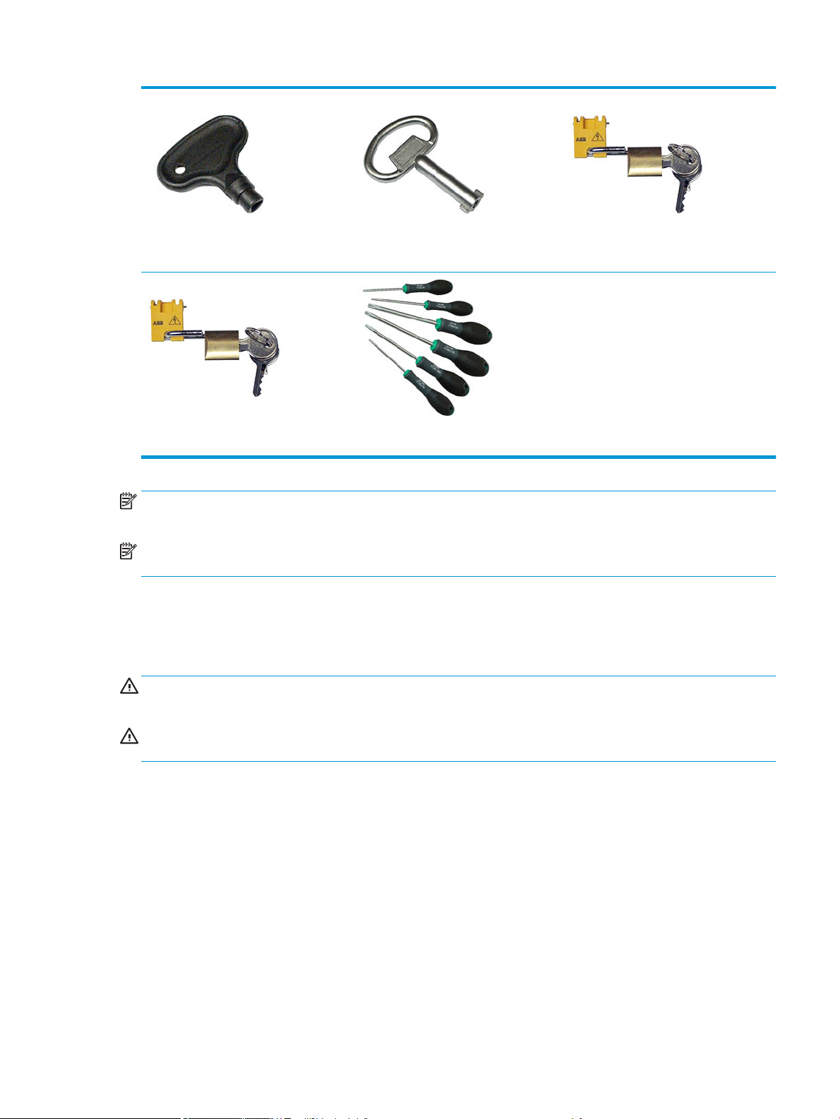
Maintenance key E-cabinet key Mains switch key
Internal Print Server key Torx screwdriver set
NOTE: During the installation of the printer, the designated personnel receive training for the safe operation
and maintenance of the printer. It is not allowed to use the printer without this training.
NOTE: After using the maintenance key to open a door, remember to lock it afterwards, and return the key to
safe and secure storage.
Warnings and cautions
The following symbols are used in this manual to ensure the proper use of the printer and to prevent the printer
from being damaged. Follow the instructions marked with these symbols.
WARNING! Failure to follow the guidelines marked with this symbol could result in serious personal injury or
death.
CAUTION: Failure to follow the guidelines marked with this symbol could result in minor personal injury or
damage to the product.
ENWW Safety precautions 7
Page 14
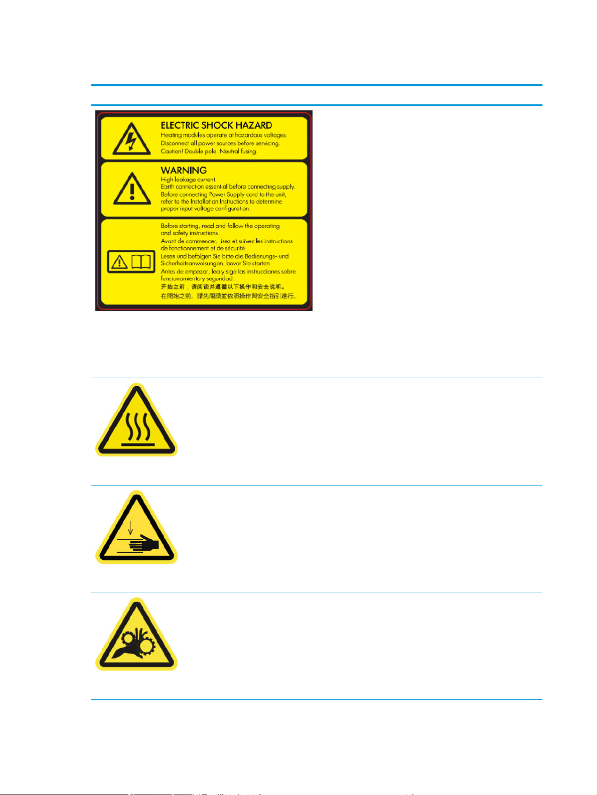
Warning labels
Label Explanation
Located on the e-cabinet.
Electric shock hazard
Heating modules operate at hazardous voltage. Disconnect power
source before servicing.
Caution! Double pole. Neutral fusing. Refer servicing to qualied
service personnel.
In case of operation of the fuse, parts of the printer that remain
energized may represent a hazard during servicing. Turn o the
printer using both Branch Circuit Breakers located in the building's
Power Distribution Unit (PDU) before servicing.
Warning
High leakage current. Current leakage may exceed 3.5 mA. Earth
connection essential before connecting supply. Equipment to be
connected to earthed mains only.
See installation instructions before connecting to the supply.
Ensure that the input voltage is within the printer's rated voltage
range. The printer requires up to two dedicated lines, each
protected by a branch circuit breaker according to site preparation
requirements.
Read and follow the operating and safety instructions before
starting the printer.
Located on the curing modules and universal support beam
Located on each side of substrate path, close to PPS gear
Risk of burns. Do not touch the internal enclosures of the printer's
drying and curing modules, universal support beam, and LED’s
array and enclosures when accessing substrate path.
Crush hazard. Do not touch PPS while moving. When substrate has
been loaded, the carriage descends into its normal position, and
could crush your hand or anything else left underneath it.
Risk of trapped ngers. Do not touch gears while moving. Danger
that your hands may become trapped between gearwheels.
Located on each side of substrate path, and close to PPS gear
8 Chapter 1 Introduction ENWW
Page 15
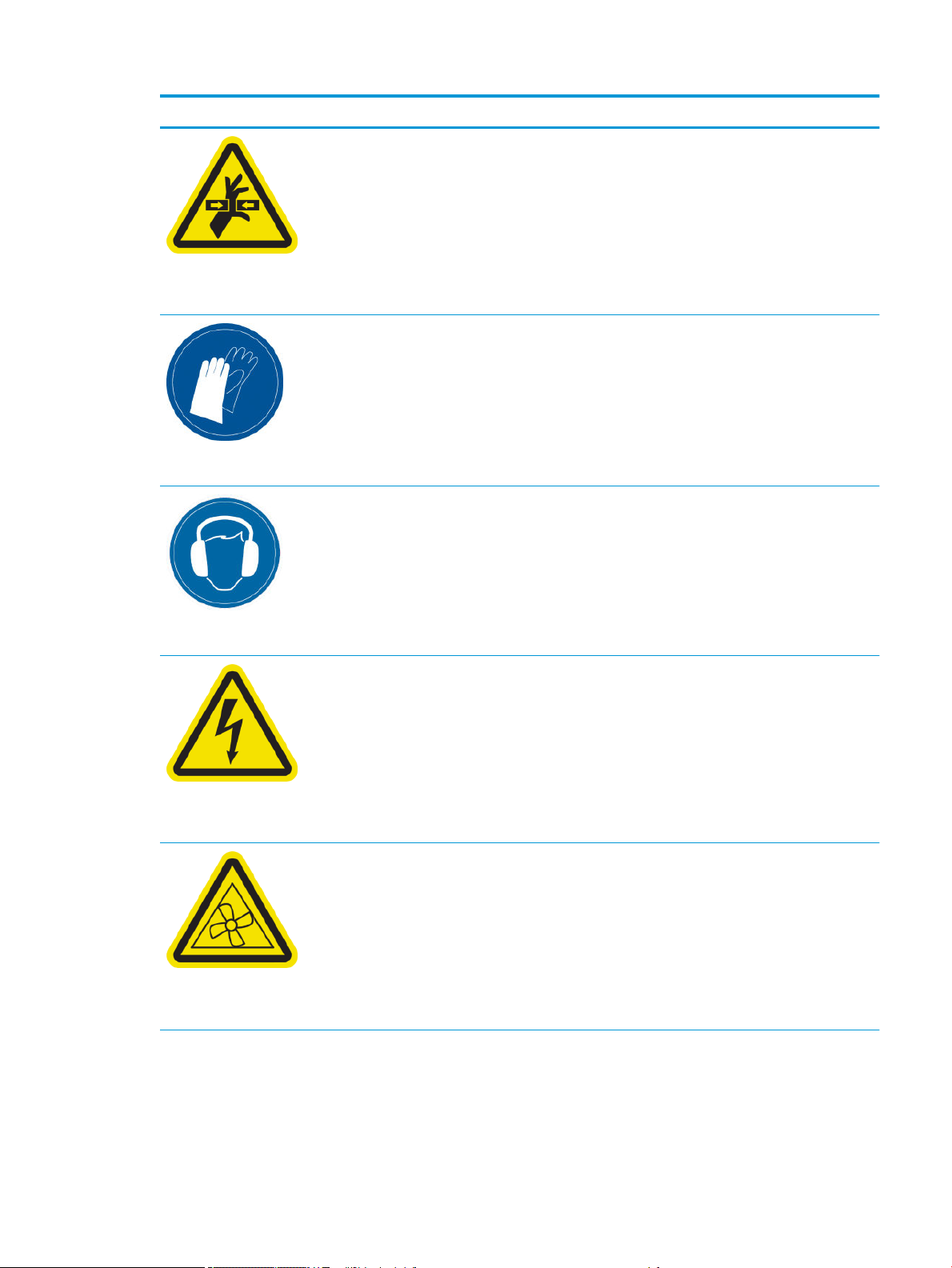
Label Explanation
Hazardous moving part. Keep away from moving carriage
printhead. When printing, the printhead carriage travels back and
forth across the substrate.
Located internally on substrate path and on printhead cleaning roll
(web wipe); for maintenance/service personnel only
You are recommended to wear gloves when handling ink cartridges,
printhead cleaning cartridges and the printhead cleaning container.
Located on ink waste bottle and web wipe
Sound pressure level could exceed 70dB(A) in certain print modes.
Hearing protection may be required.
Located on rear side on left cover
Located internally on heating modules and electrical cabinets; for
maintenance/service personnel only
Located internally, close to vacuum fan blades and Dryer PCA
cooling fan; for maintenance/service personnel only
Electric shock hazard. Disconnect power before servicing. Heating
modules and electrical cabinets operate at hazardous voltage.
Hazardous moving parts. Keep away from moving fan blades.
Internal close to Vacuum Fan Blades and Dryer PCA cooling fan.
ENWW Safety precautions 9
Page 16
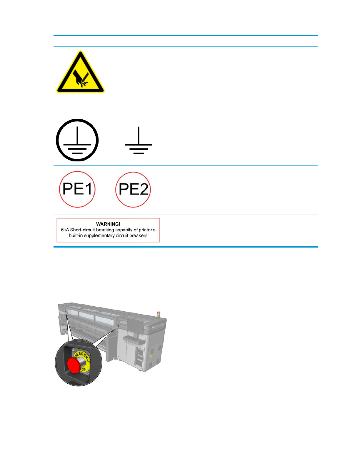
Label Explanation
Risk of cutting your ngers. Do not touch in-line slitters during
printing.
Handle in-line slitters with care and store them safely in their box
when not being used with the printer.
Located on each side of the in-line slitters and close to carriage
encoder strip
Identies the Protective Earth (PE) terminal for qualied electrician,
and bonding terminals for maintenance/service personnel only.
Earth connection essential before connecting supply.
Identies the Protective Earth (PE) terminal for qualied electrician,
and bonding terminals for maintenance/service personnel only.
Earth connection essential before connecting supply.
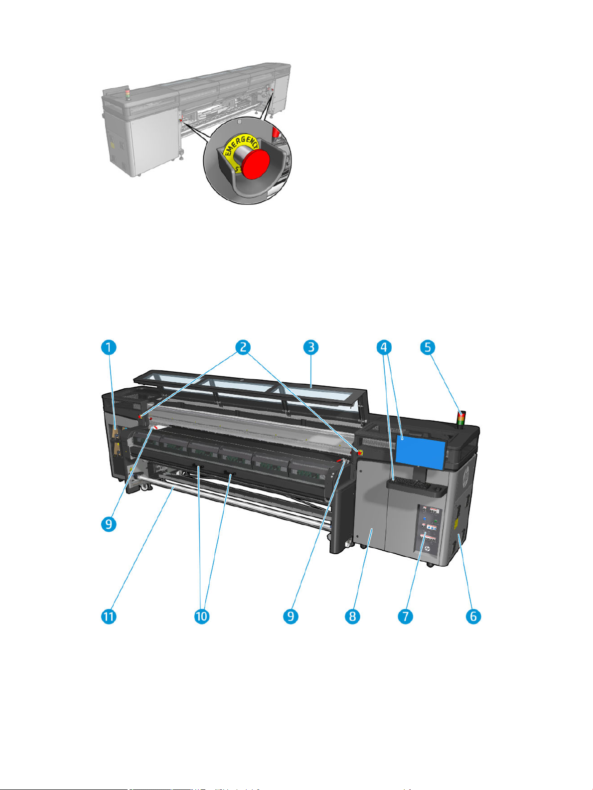
Emergency stop buttons
There are four emergency stop buttons distributed around the printer. If an emergency occurs, simply push one
of the emergency stop buttons to stop all printing processes. A system error message is displayed, and the fans
turn at maximum speed. Ensure that all emergency stop buttons are released before restarting the printer.
Identies the short-circuit breaking capacity of printer’s built-in
supplementary circuit breakers beside mains input terminal, for
qualied electrician and maintenance/service personnel only. Earth
connection essential before connecting supply.
10 Chapter 1 Introduction ENWW
Page 17
For safety reasons, access to the print zone is not permitted while printing is in progress. Therefore, if the
window or the loading table is opened, power to the carriage and to the drying and curing module is
disconnected. The print is cancelled and a system error may be displayed.
Main components
The following views of the printer illustrate the main components.
Front view
1. Ink cartridges
2. Emergency stop buttons
3. Front window for carriage and printzone access
4. Built-in computer
ENWW Main components 11
Page 18
5. Printer status beacon
6. E-cabinet
7. Power switches, lights, and circuit breakers
8. Printhead cleaning roll door
9. Curing module latches, one on each side
10. Curing module handles
11. Substrate output spindle
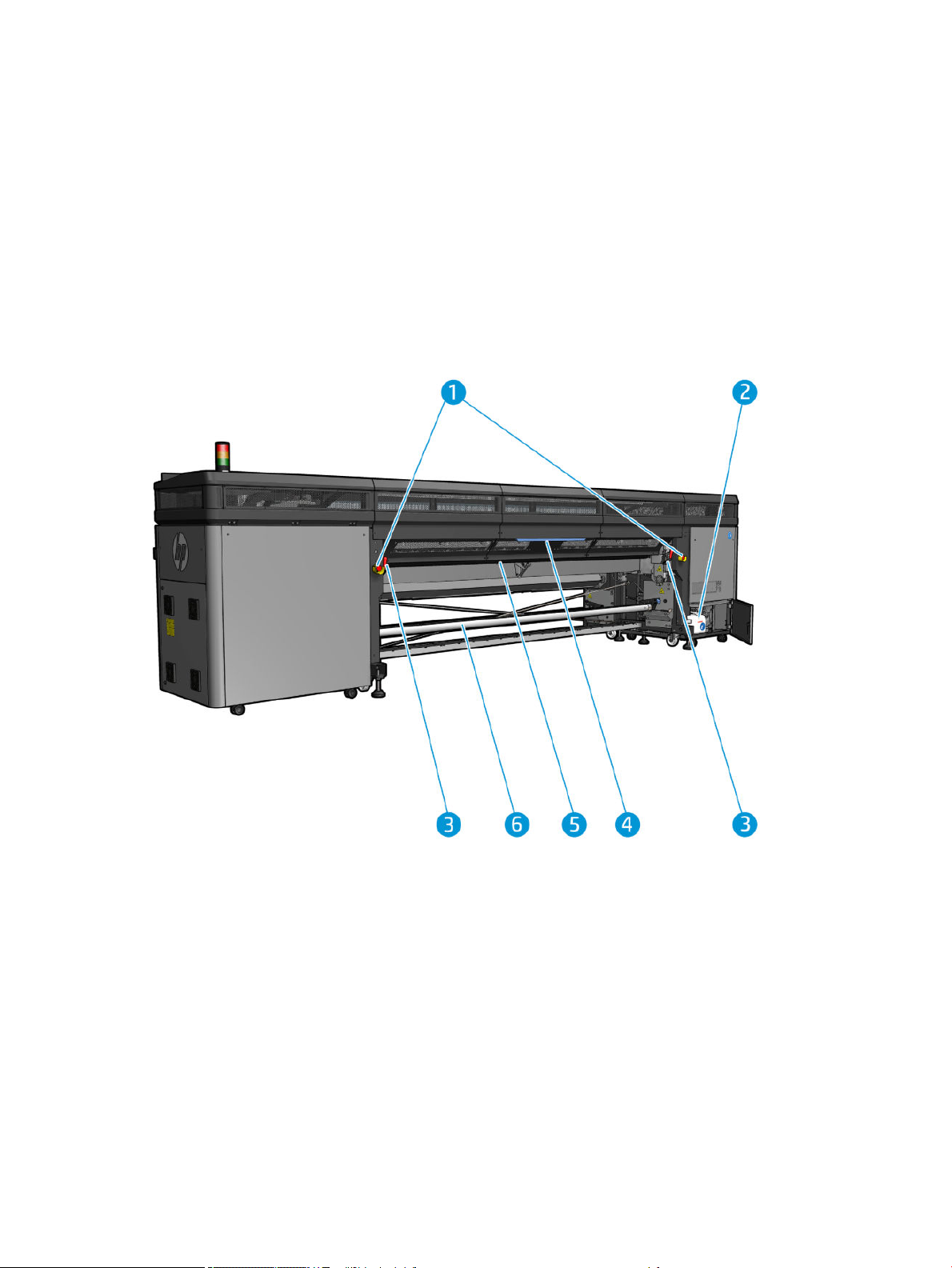
Rear view
1. Emergency stop buttons
2. Condensation collector bottle
3. Loading table latches, one on each side
4. Loading table
5. Drive roller
6. Substrate input spindle
12 Chapter 1 Introduction ENWW
Page 19
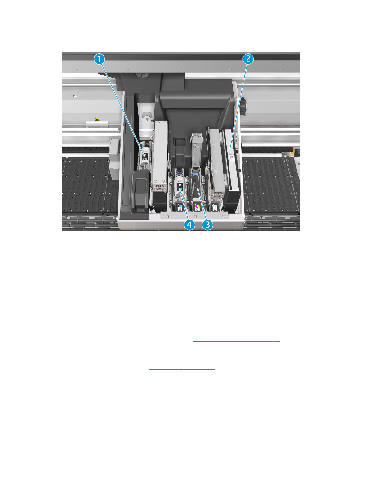
Carriage view
1. Optimizer printhead latch
2. Aerosol lters
3. Printhead
4. Color printhead latch
Printer software
Your printer requires the following software:
●
The HP Internal Print Server is provided with your printer and is already installed in the printer's built-in
computer. It displays printer alerts and a summary of printer status, manages print jobs, and must be used
to interact with the printer in various ways. See HP Internal Print Server on page 17.
●
The HP Print Care program is provided with your printer and is already installed in the printer's built-in
computer. It displays printer status and history in detail, and helps you to maintain the printer and solve any
problems that may arise. See HP Print Care on page 143.
●
A Raster Image Processor (RIP) should be run on a separate computer; it cannot be installed on the
printer's built-in computer. It is not provided with the printer and should be obtained separately. The printer
is JDF-enabled. If your RIP supports this interface, it can retrieve and display printer and job status.
ENWW Printer software 13
Page 20
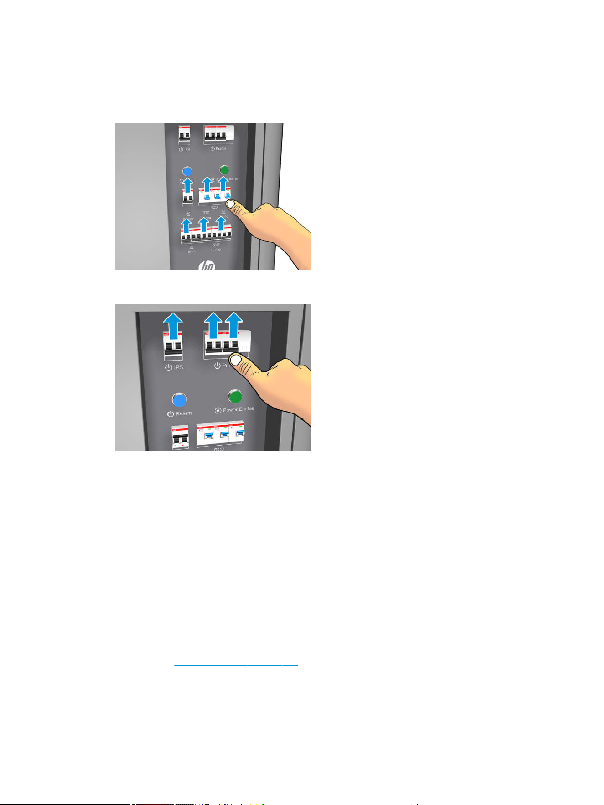
Turn on the printer for the rst time
1. Make sure that the two bottom rows of circuit breakers at the front right of the printer are all in the up
position.
2. Turn the main switch to the on position, and also turn on the PC switch beside it.
3. Check that all three green lights are on. In normal operation these lights should always be on. If any of
them are o, check the Internal Print Server in case there is a system error, and see Printer messages
on page 369 or check with your electrician.
4. Wait for the Internal Print Server to tell you that the printer is waiting for rearm.
5. Perform a visual check of the printer.
6. Press the blue rearm button at the front right of the printer. This enables all of the printer's high-power
subsystems.
7. Check that the printer-enabled green light turns on. In normal operation this light should always be on. If at
any time you notice that this light is o, check the Internal Print Server in case there is a system error, and
see Printer messages on page 369.
8. Wait for the Internal Print Server to indicate that the printer is ready. This can take several minutes. When
initialization is complete, the Internal Print Server displays a Ready message. If a system error message is
displayed, see Printer messages on page 369.
Turn the printer on and o
The printer has three power-o levels. Each of them goes deeper, until you reach complete shutdown at level 3.
14 Chapter 1 Introduction ENWW
Page 21
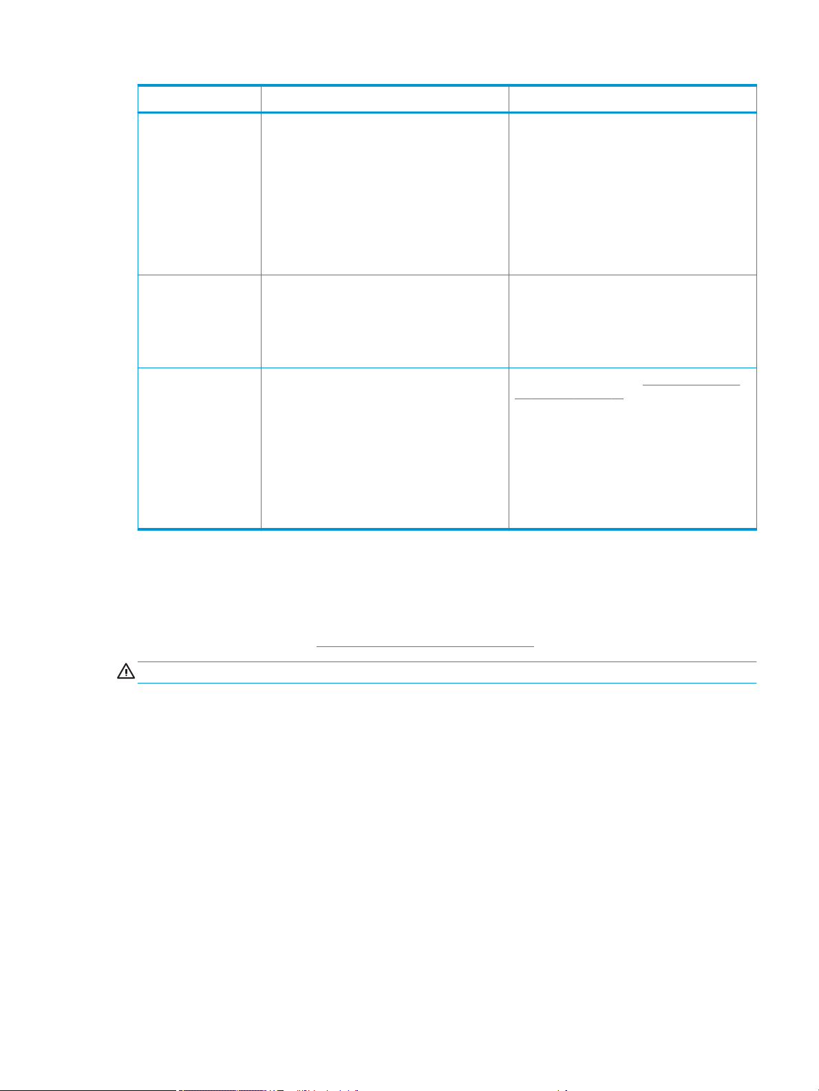
Level Turn o Turn on
1: Major power
electronics and engine
o.
2: All printer systems o
(recommended).
3: All printer systems and
Internal Print Server o.
Wait for the Internal Print Server to indicate that the
printer is ready, then turn o the high-power
subsystems by pressing the shutdown icon near the
top left corner of the screen. Wait until the Internal
Print Server reports that it has lost its connection to
the printer.
NOTE: After the printer electronics have been
turned o at the Internal Print Server, the fans turn at
maximum speed for safety reasons. This is normal
behavior and not a cause for concern.
After completing level 1, turn o the main switch. The
fans should stop.
After completing level 2, shut down the Internal Print
Server from the Windows Start button, and wait until
you see a black screen with the message No input
signal.
CAUTION: The computer may be damaged if it is
turned o incorrectly.
Once the Internal Print Server is completely o and
you see No input signal on the screen, turn o the
computer power switch.
Click the Wake Up button up in the top left corner of
the Internal Print Server window, and wait for the
printer to turn on the high-power systems.
When prompted, press the blue rearm button at the
front right of the printer.
After completing level 1, turn on the main switch, and
ensure that the circuit breaker beside it is on.
When prompted, press the blue rearm button and
wait for the Internal Print Server to announce that the
printer is Ready.
After completing level 2, see Turn on the printer for
the rst time on page 14.
Move the printer
If you wish to move the printer a short distance on the same site, across a horizontal oor with no steps and no
slopes of more than 3% inclination, see the following instructions. For more dicult movement operations, call
your service representative (see HP Customer Care Centers on page 362).
CAUTION: Slopes steeper than 3% may cause serious damage to the printer.
1. Turn o the printer.
2. Disconnect all power and network cables from the printer.
3. Raise the feet gradually, applying two turns each time to each foot so that the wheels (A) touch the ground.
To raise a foot:
a. Use a 24mm (15/16 in) open end wrench to unlock the nut at the top of the foot.
b. Rotate the nut manually down the bolt. Leave about 2cm (0.8 in) clearance at the bottom between
nut and foot.
c. Use a 16mm (5/8 in) open end wrench to rotate the foot upwards. Use the at hexagonal faces at the
bottom of the bolt to t the wrench.
d. Raise the foot as far as the bolt allows.
e. Use the 24mm (15/16 in) open end wrench to lock the nut again.
ENWW Move the printer 15
Page 22
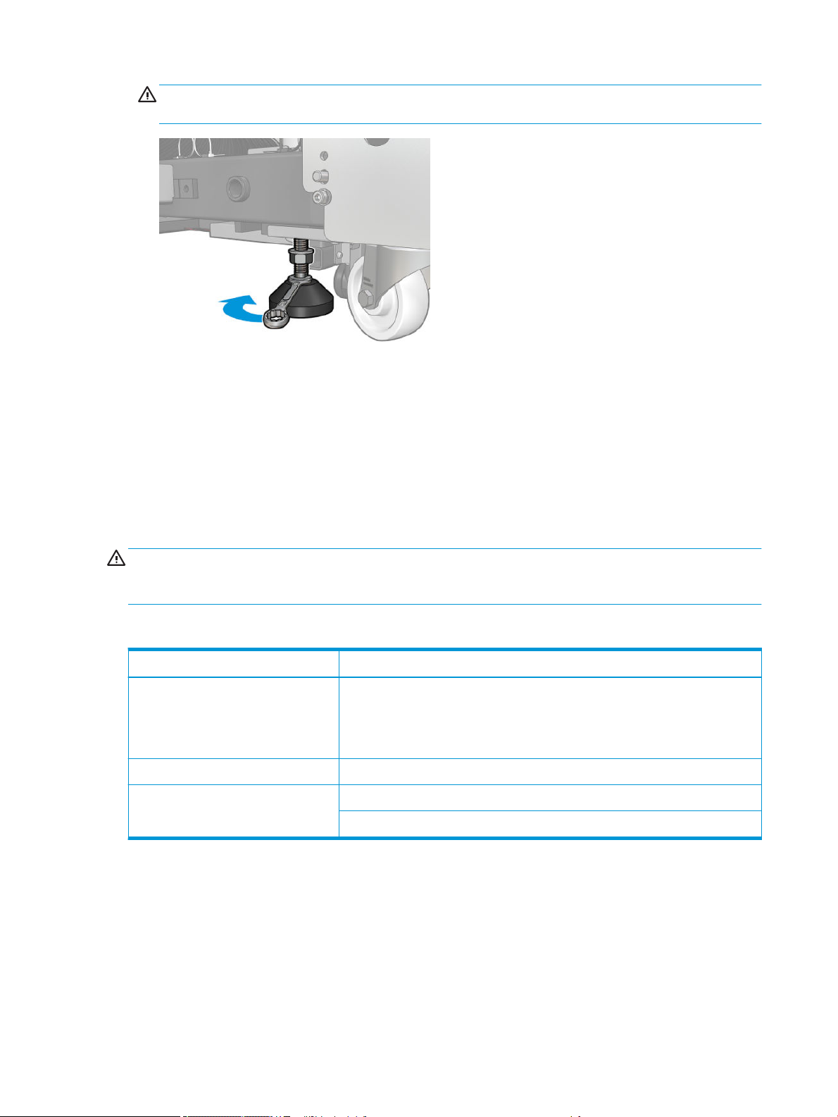
CAUTION: Take care to raise the feet as high as you can. They may break if they touch the ground while
the printer is in motion.
4. Push the printer from the outside corners of the main body. Remember to avoid slopes steeper than 3%.
5. Once the desired destination is reached, reverse the process described above to secure the printer in
position.
After moving the printer, you may in some cases need an electrician to reconnect the power cables. You may
also need to recongure the network, from the printer's built-in computer and from the RIP computer. See the
Installation Guide for more details, including the minimum space required around the printer.
Printer status beacon
CAUTION: The information provided by the printer status beacon is for functional information purposes only,
and is not related to any safety provision, or safety states. Warning labels on the printer must be always
considered when operating the printer, and they prevail over any status indicated by the printer status beacon.
Printer status beacon messages mean:
Color Description
Red Unexpected printing interruption. A job that had started to print stopped unexpectedly and
Orange Warning alert present in the IPS
Green Idle
appears as Failed. Attention required.
An UI user conrmation appears in the IPS window. When attended to, the red color in the
beacon changes to reect the state of the printer.
Printing
16 Chapter 1 Introduction ENWW
Page 23
2 HP Internal Print Server
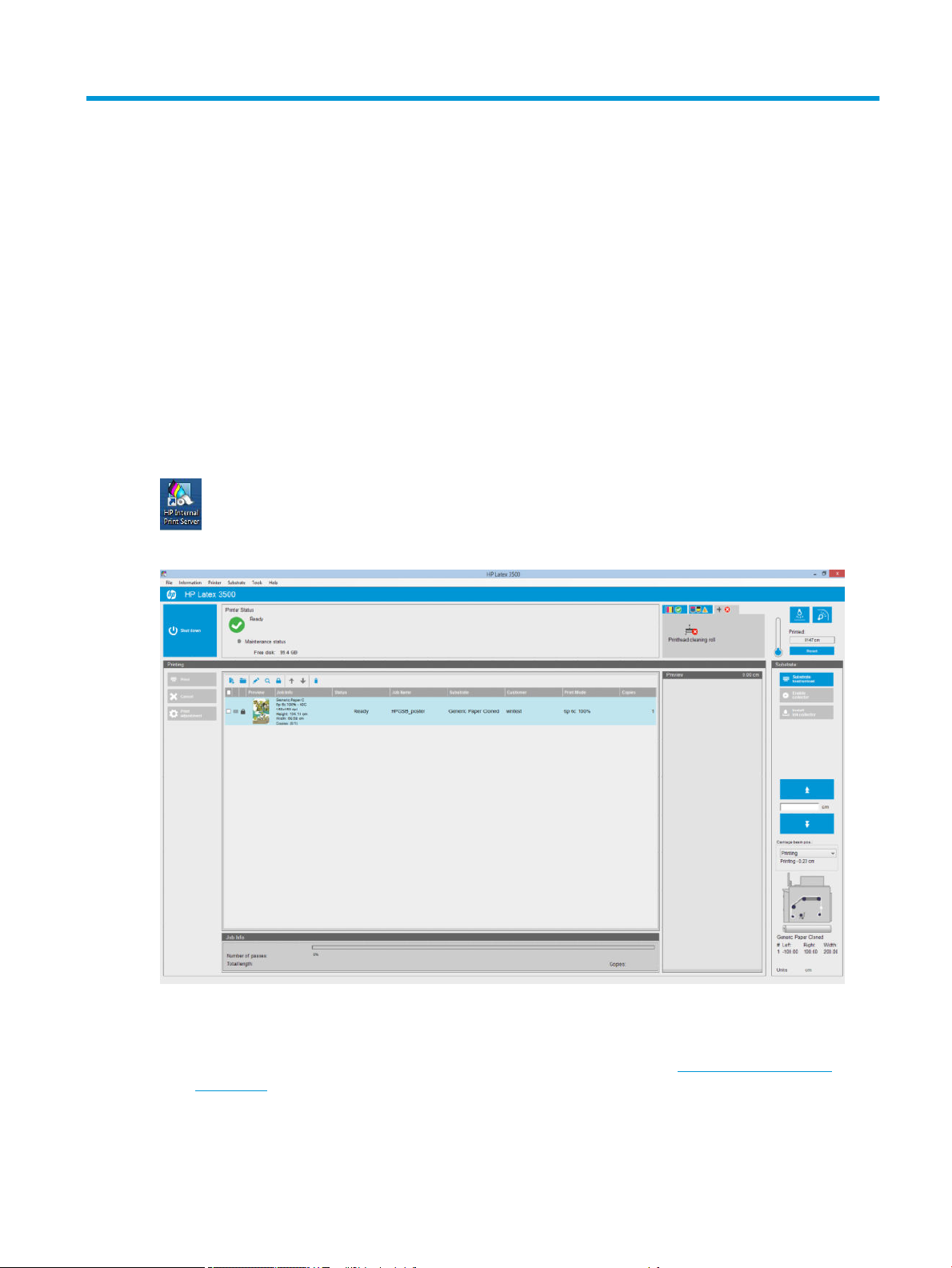
Start the Internal Print Server
The Internal Print Server starts automatically with Windows, and runs continually, in the background if not in the
foreground.
If for some reason it has stopped running, or its window is not visible, you can start it from the Windows Start
menu or by double-clicking its icon on the desktop.
When it starts, the main screen appears.
In the main screen:
●
You can shut down the printer by pressing the Shut down button at the top left.
●
The top central pane shows the printer status and maintenance status. See Printer status and alerts
on page 22.
●
The thermometer to the right of the status pane shows the curing temperature.
ENWW Start the Internal Print Server 17
Page 24

●
To the right of the thermometer, you can see a summary of the status of the ink cartridges, the printheads,
and the printhead cleaning roll.
●
The System Preheat button preheats the whole system in printer ready status. It is useful for cold
environments to avoid time-out errors during warm-up. It enables drying and curing to slowly preheat the
system. Heating duration can be set from 1 to 60 minutes in Tools > Preferences > Additional Settings.
●
The Printing pane occupies most of the window, and includes:
–
The Print, Cancel, and Print adjustment buttons
–
The job queue
–
The print preview and job settings
●
The Substrate pane includes the Substrate load/unload, Enable collector, and move carriage beam buttons;
and information about how the current substrate is loaded.
Change the language of the Internal Print Server
When the Internal Print Server starts, it uses the language selected in the Windows Regional and Language
Options. To change the selected language:
1. Open the Control Panel from the start menu.
2. If you are using the Category View of the Control Panel, open the Clock, Language, and Region category.
3. Open the Regional and Language Options.
4. In the Formats tab, change the current format to correspond with the language you want.
5. Press the OK button.
The change takes eect when Windows is restarted.
Change the units of measurement in the Internal Print Server
To change the units of measurement in the Internal Print Server, select the Tools > Preferences > Units. You can
change the units of length and temperature.
Set the Internal Print Server preferences
To change the Internal Print Server's preferences, select Preferences from the Tools menu. In the Preferences
window, you will see four tabs.
18 Chapter 2 HP Internal Print Server ENWW
Page 25
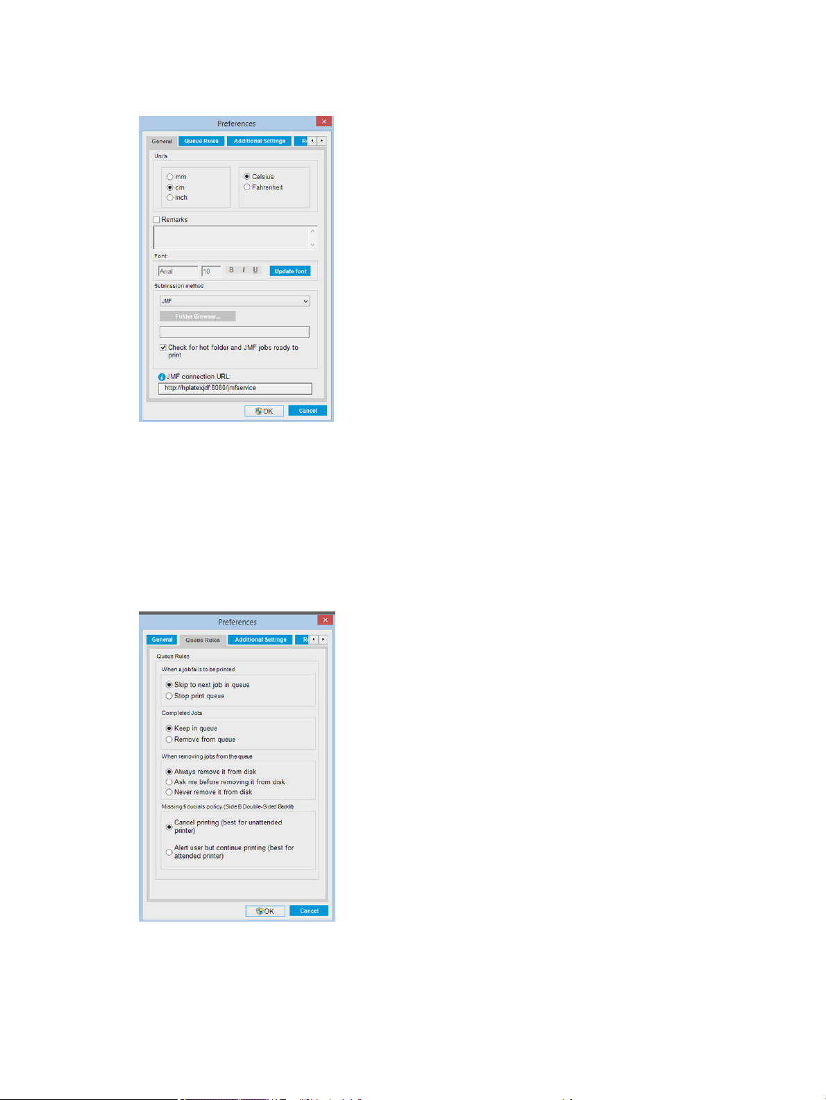
General tab
●
●
●
Units of length and temperature
Remarks (to add as a footer to the printed le)
Font of footer text
●
Hot folder
●
JMF connection url
Queue Rules tab
ENWW Set the Internal Print Server preferences 19
Page 26
●
Action when job fails
●
Action when job has been printed
●
Action when job is removed from the queue
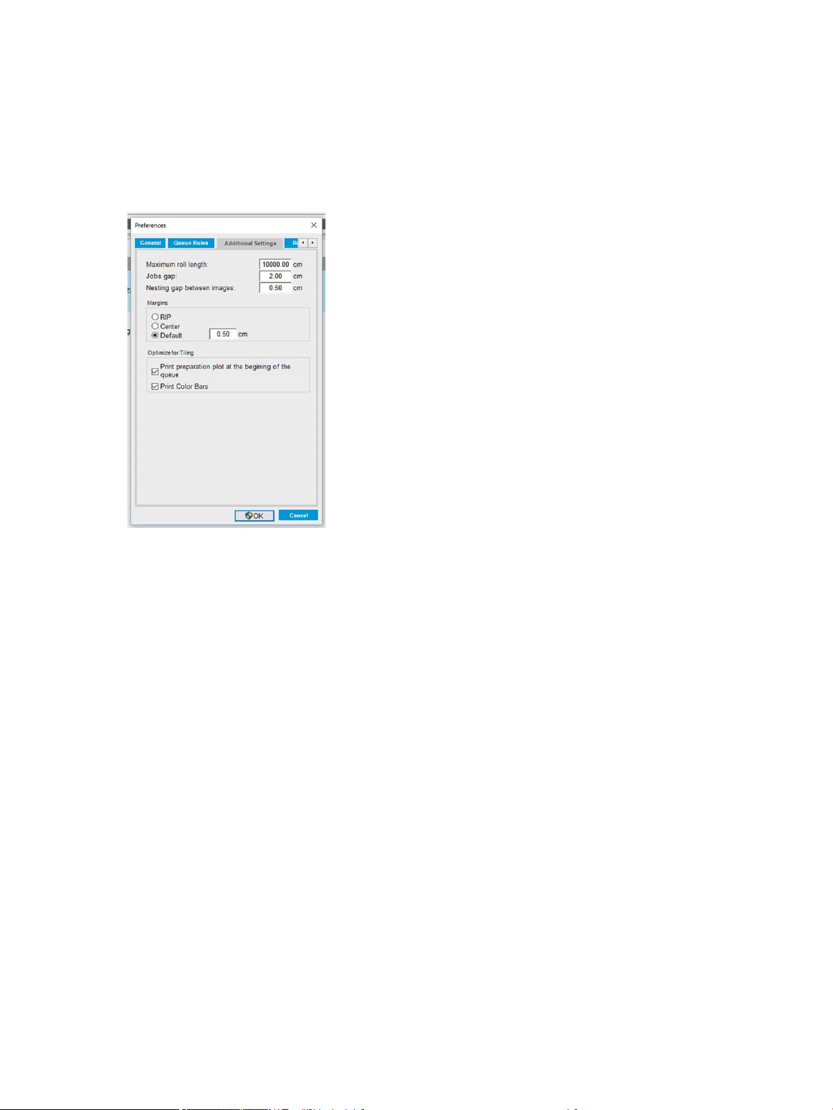
Additional Settings tab
●
Maximum roll length
●
Gap between jobs
●
Nesting gap between images
●
Margins:
–
RIP: Margins are set as dened in the RIP.
–
Center: The image is horizontally centered on the loaded substrate.
–
Default: The default margins are set to 5.0 mm (0.02 in). You can dene the default left margin in the
Job Properties window.
●
Heating duration
●
Optimize for tiling:
–
Print preparation plot at the beginning of the queue.
–
Print color bars.
20 Chapter 2 HP Internal Print Server ENWW
Page 27

Remote Assistance tab
●
Enable remote assistance
●
Enable proxy server and give details
●
Register Remote/Mobile Device
Internal Print Server menus
The Internal Print Server provides the following menus.
ENWW Internal Print Server menus 21
Page 28

The File menu
The Information menu
The Printer menu
●
Add New Job
●
Add Existing Job
●
Edit Job
●
Delete Job
●
Exit
The Substrate menu
●
Load/Unload
●
Settings
●
Create
●
Edit
●
Clone
●
Optimize for tiling
●
Rename
●
Remove
●
Alerts
●
Supplies
●
Service information
The Tools menu
●
Preferences
●
HP Scitex Print Care
●
HP Proactive Support
●
Firmware update
●
Wake up
●
Shut down
●
Reinitialize carriage
●
Printing adjustments
●
Printhead alignment
●
Printhead cleaning
●
Replace printheads
●
Replace cleaning roll kit
●
Advance calibration
●
Enable/Disable collector
The Help menu
●
About
●
User's guide
●
Color calibration
●
Presets management
●
Search substrate online
Printer status and alerts
The Internal Print Server displays the general status of the printer, the maintenance status, the loaded substrate,
and the ink system.
The printer can communicate the following types of alerts:
Printer status
●
Errors: When the printer is unable to print.
●
Warnings: When the printer needs attention for an adjustment, such as a calibration, preventive
maintenance or ink cartridge replacement.
A summary list of printer alerts appears in the main window of the Internal Print Server. To display a more
complete and detailed list, select Information > Alerts.
For more information about a particular alert, see Printer messages on page 369.
22 Chapter 2 HP Internal Print Server ENWW
Page 29

Maintenance status
●
Green light: No maintenance is needed.
●
Yellow light: Maintenance procedure date is approaching. Press the yellow button to check Print Care for
details. See HP Print Care on page 143.
●
Orange light: Maintenance is required. Press the orange button to check Print Care for details.
●
Red light: Maintenance is required urgently. Press the red button to check Print Care for details.
●
Grayed out: Print Care is not running. Press the orange button.
Update the rmware and the Internal Print Server
TIP: When updating the rmware and the Internal Print Server, rst update the rmware and then the Internal
Print Server.
Update the rmware
From time to time rmware updates will be available from HP that increase the printer's functionality and
enhance its features.
Firmware updates can be downloaded from the Internet and installed in your printer using the Internal Print
Server: select Firmware update from the Tools menu.
Follow the instructions on your screen to download the rmware le and store it on your hard disk. Then select
the downloaded le and click Update.
The rmware includes a set of the most commonly used substrate presets. Extra substrate presets can be
downloaded separately; see Substrate presets on page 63.
Update the Internal Print Server
IMPORTANT: Remove the previous version of the Internal Print Server in the printer's built-in computer before
installing the new version.
1. Remove the current version of the Internal Print Server through the control panel. Select Uninstall Internal
Print Server Application (this deletes any current job in the queue, but not ripped les).
2. Download the le to the built-in computer's hard disk (but not to the desktop).
ENWW Update the rmware and the Internal Print Server 23
Page 30

3. Unzip/extract the les HPIPS.msi and Setup.exe.
4. Run the le Setup.exe and follow the onscreen instructions until the new software is installed.
Update the HP IPS Services
IMPORTANT: Remove the previous version of the Internal Print Server in the printer's built-in computer before
installing the new version.
1. Remove the current version of the Internal Print Server through the control panel. Select Uninstall Internal
Print Server Application
2. Download the le to the built-in computer's hard disk (but not to the desktop).
3. Unzip/extract the les HPIPSServices.msi and Setup.exe.
4. Run the le Setup.exe and follow the onscreen instructions until the new software is installed.
.
24 Chapter 2 HP Internal Print Server ENWW
Page 31

3 RIP distribution
HP RIP Certication dierentiates the RIP partners who reach a specic and superior level of integration,
compatibility, and performance with the HP Latex 1500 Printer.
HP has increased the functionalities and RIPs certied for the HP Latex 1500 Printer.
The compatibility support matrix below presents the certied RIP partners and versions. As well as the dierent
functionalities supported by each specic RIP partner, all certied RIP partners support, at least, all the
mandatory functionalities. You can nd more information on the HP Latex Knowledge center via the following
link: http://h20435.www2.hp.com/t5/HP-Latex-Blog/Certied-RIPs-to-enable-seamless-integration-with-HP-
Latex-1500/ba-p/298577.
ENWW 25
Page 32

4 Printing workows integration
Introduction to JDF
What is JDF?
JDF is a software method by which devices from a variety of vendors and manufacturers can interoperate
together. It uses a text-based language known as XML that is compliant with many devices and workow
controllers in varying vertical print markets.
JDF implementation is typically based upon an MIS system to be use for job scheduling, submission, accounting,
and costing. An integrator typically interfaces an MIS system to the devices that are present in a workow
through JDF technology.
JMF is a communication protocol (based upon the JDF specication) that allows devices to communicate job
status information and other real-time job metrics and parameters. It can be used to poll a device for status or to
watch a device at regular intervals.
Benets of working with JDF for le submission
JDF can be useful in providing an accurate MIS-driven way to know the job status of content as well as when a
device has completed a job. Since the role of an MIS is to track, schedule and cost-account for a job, JDF/JMF
allows for a simple way to interface devices to an MIS for this task.
JDF and JMF can be used to be able to analyze and later perform accounting principles upon work created in a
JDF workow. A detailed analysis can be performed after a day or series of jobs to see the prot margin of a job,
the costs and materials consumed, as well as inventory control and stock consignment.
HP is a partner member of the CIP4 organization, and you can obtain many more details about JDF at the CIP4
www site at http://www.cip4.org.
Working with JDF
Creating JDF job tickets
JDF Implementations typically use an MIS system to control and monitor a JDF/JMF workow. The MIS can then
monitor a device’s status, can track time and consumables and provide interfacing with counting and inventory
control modules integrated into an MIS. An MIS is typically the origin of a JDF job and resultant ticket. JMF
communication can be used to send that ticket information to production milestones. An MIS is typically the
origin of a JDF job and resultant ticket. JMF communication can be used to send that ticket information to
production milestones.
26 Chapter 4 Printing workows integration ENWW
Page 33

What information is captured by the HP Latex 1500 printer series and what can be
communicated by JMF to an MIS?
The printer implements a subset of the JDF 1.5 specication, using JMF. This allows it to communicate printerstatus, and notications together with job status, job ink, and substrate consumption to external applications.
NOTE: It is important to consider the fact that the RIP is capable of combining several jobs into one for the
purpose of substrate optimization, and nishing. In this example, the printer sees the print as one job. In this
situation, the MIS should query the RIP for the status of each individual job on the nest.
The RIP application can retrieve substrate and consumable tracking to report back to MIS.
Guidelines for Integration
How to integrate the HP Latex 1500 printer series into CALDERA RIP
CALDERA RIP can take advantage of the JDF interface in the printer by selecting the option on the printer driver
setup. Once the JDF interface is enabled, the RIP will display printer status and notications together with job
status, job ink and substrate consumption.
In order to activate this functionality in the CALDERA RIP, you need to type the printer's JMF url in the JDF area of
the printer conguration dialog (IPS URL). Please, make sure you have the latest driver available from the
CALDERA Website.
Once congured, you can display the printer status by opening the info window in the print client, and opening
the spooler for the job status.
ENWW Working with JDF 27
Page 34

To obtain the JMF URL: Go to the IPS PC, on the Internal Print Server SW, and then Tools>Preferences>General.
If there are problems using the printer’s hostname, switch to the printer’s IP using the HP Latex 1500 System
Conguration Tool. For more details refer to the Service Manual or talk to your network administrator to solve
hostname resolution.
How to integrate the HP Latex 1500 printer series into ONYX RIP
ONYX can take advantage of the JDF interface in the printer by selecting the option on the printer driver setup.
Once the JDF interface is enabled, the RIP will display printer status and notications together with job status, job
ink and substrate consumption.
In order to activate this functionality in the ONYX RIP, you need to type the printer's JMF url in the JDF area of the
printer conguration dialog (JDF URL). Please, make sure you have the latest driver version from the ONYX
Download manager.
Once congured, you can display the printer and job status opening the info window in the RIP queue.
28 Chapter 4 Printing workows integration ENWW
Page 35

To obtain the JMF URL: Go to the IPS PC, on the Internal Print Server SW, and then Tools>Preferences>General.
If there are problems using the printer’s hostname, switch to the printer’s IP using the HP Latex 1500 System
Conguration Tool. For more details refer to the Service Manual or talk to your network administrator to solve
hostname resolution.
Job submission methods
The HP Latex 1500 supports two le submission methods (in addition to open a le directly in HP IPS UI):
Select the submission method within the Preference dialog in HP IPS Tools>Preferences>General, in the Submit
method drop down list:
ENWW Working with JDF 29
Page 36

Hotfolder: Select a shared folder in the HP IPS PC and the RIP copies the output job there, the IPS automatically
loads jobs into the queue.
NOTE: The shared folder should be the same as the one congured in the RIP.
JMF: The RIP sends the location of the job via a JMF command and the IPS automatically looks for the les there
and loads them directly into the printer queue.
Not specify: Load the le manually in the IPS File>Open.
Removing a queued job from the RIP:
Remove a job from the IPS/printer queue directly via the RIP interface, but only if it was submitted using the JMF
method.
How to integrate the HP Latex 1500 printer series into an MIS system or production control software
Specic RIP/MIS implementations will require vendor specic congurations.
MIS or Production Control Software applications can retrieve printer status and notications together with job
status, job ink and substrate consumption, from the printer via the HP JDF/JMF Interface. It is also possible to
remove a job in the printer queue via the HP JDF/JMF Interface.
As explained in the previous section, if the RIP combines several jobs into one before sending it to the printer, the
recommendation is to connect the MIS or Production Control software to the RIP instead of the IPS in order to get
the grouped jobs’ individual job status.
Be sure to assign unique names to each job in order to identify them on the gathered information from the
printer.
30 Chapter 4 Printing workows integration ENWW
Page 37

If you are using CALDERA 10.2 RIP, then the MIS can communicate using the Caldera Nexio module. Caldera
Nexio is a tool that connects the Caldera RIP and other third-party software using standard JDF/JMF protocols,
making it possible to produce automatic sequences of actions that speed up production and advanced reports to
improve operations. Please, contact CALDERA for further information.
ONYX customers wishing to integrate with MIS solutions can use the ONYX Connect module to communicate via
JDF. ONYX Connect does not currently support JMF. Please contact ONYX for further information.
If you are using another RIP solution, please contact your specic RIP vendor for JDF/JMF conguration and
interface guidelines.
MIS vendors or customers that would like to integrate the printer with a solution directly, can obtain the HP
specically supported JDF Software Development Kit from the HP Solutions Portal: https://developers.hp.com/
lfp-enroll.
ENWW Working with JDF 31
Page 38

5 Handle the substrate
Supported substrate types
The following substrate types are compatible with your printer. For specic substrate settings and proles, see
the Online substrate manager on page 77.
Self-adhesive vinyl
●
Cast self-adhesive vinyl
●
Calendered self-adhesive vinyl
●
Perforated self-adhesive vinyl
●
Transparent self-adhesive vinyl
PVC banner
Paper
●
Reective self-adhesive vinyl
●
Frontlit banner
●
Backlit banner
●
Scrim banner
●
Scrimless banner
●
Mesh banner with liner
●
Blockout banner
●
Truck curtain banner or tarpaulin
●
Coated paper
●
Uncoated paper
●
Photo paper
●
Photorealistic paper
●
Blue-back paper
●
Self-adhesive paper
32 Chapter 5 Handle the substrate ENWW
Page 39

PP and PE lm and banner
●
Polypropylene (PP) lm
●
Synthetic paper (such as Yupo)
●
Tyvek
●
Coated PE/HDPE (polyethylene) banner
PET lm
●
Polyester (PET) backlit lm
●
Polyester (PET) frontlit lm
●
Polyester (PET) grey-back lm
Textile
To check the porosity of your substrate, see Check the porosity of your substrate on page 34.
●
Polyester textile and fabric
●
Textile banner
●
Backdrops
Wall covering
●
Textile mesh with liner
●
Frontlit textile with liner if porous
●
Backlit textile with liner if porous
●
Canvas
●
Flag and voile with liner
●
Cotton textile
●
Self-adhesive textile
NOTE: This is an application example, not a selectable category.
●
Paper wall covering or wallpaper
●
PVC wall covering
●
Pre-pasted wall covering
●
Non-woven wall covering
●
Textile wall covering
●
Self-adhesive wall covering
ENWW Supported substrate types 33
Page 40

Check the porosity of your substrate
1. If the printer has any substrate loaded, unload it.
2. Cut a piece of self-adhesive vinyl white gloss 15 × 50 mm (0.6 × 2 in) in size.
3. Stick it to the platen, covering the substrate-advance sensor.
4. Load the substrate that you want to check.
5. Open your RIP software.
6. Obtain the test le from the printer’s built-in computer: C:\Users\hplatex\Documents\HP IPS
\InkTrespassingCheck\Ink_trespassing_check.pdf.
7. Print the test le using the number of passes and substrate preset that you intend to use in future with this
substrate (or a similar prole in terms of ink limit).
8. Unload the substrate.
9. Remove the strip of self-adhesive vinyl from the platen.
10. Look at the self-adhesive vinyl you have taken from the platen.
●
If the strip is completely white (has no ink on it), the tested substrate is non-porous and may be used
for printing as described in this guide.
11. Clean the print zone, see Clean the print zone on page 198.
Supported HP substrates
Category Substrate
HP Banners
HP Self-adhesive
Materials
HP HDPE Reinforced Banner
203 microns (8 mil) • 180 g/m2 (5 oz) • 45,7 m (150 ft)
HP Everyday Matte Polypropylene, 3-in Core
203 microns (8 mil) • 120 g/m² • 61 m (200 ft)
HP Air Release Adhesive Gloss Cast Vinyl
Without liner: 50 microns (2 mil) • 100 g/m² • 45,7 m (150 ft)
With liner: 241 microns (9.5 mil) • 260 g/m² • 45,7 m (150 ft)
HP One-view Perforated Adhesive Window Vinyl
Without liner: 165 microns (6.5 mil) • 155 g/m² • 50 m (164 ft)
With liner: 406 microns (16 mil) • 288 g/m² • 50 m (164 ft)
Automatic
printhead
alignment
NO NO Trade show and event
YES YES Trade show and event
YES YES Trade show and event
NO NO Fleet graphics and vehicle
Color
calib. Applications
displays, POP and retail
displays, Banners
displays, POP and retail
displays, Posters and
photo enlargements,
Banners
displays, Fleet graphics
and vehicle wraps,
Signage
wraps, Window graphics,
POP and retail displays
34 Chapter 5 Handle the substrate ENWW
Page 41

Category Substrate
Automatic
printhead
alignment
Color
calib. Applications
HP Films
HP Permanent Gloss Adhesive Vinyl
Without liner: 121 microns (4.8 mil) •150 g/m² • 100 g/m² • 45,7
m (150 f • 91,4 m (300 ft)
With liner: 266 microns (10.5 mil) • 280 g/m² • 45,7 m (150 ft •
91,4 m (300 ft)
HP Permanent Matte Adhesive Vinyl
Without liner: 121 microns (4.8 mil) •150 g/m² • 45,7 m (150 f •
91,4 m (300 ft)
With liner: 266 microns (10.5 mil) • 280 g/m² • 45,7 m (150 ft •
91,4 m (300 ft)
HP Premium Removable Gloss Adhesive Vinyl
Without liner: 96 microns (3.8 mil) • 136 g/m² • 45,7 m (150 f)
With liner: 284 microns (11.2 mil) • 298 g/m² • 45,7 m (150 ft)
HP Everyday Adhesive Matte Polypropylene, 3-in Core
Without liner: 180 microns (7.1 mil) • 120 g/m² • 30,5 m (100 ft)
With liner: 215 microns (8.5 mil) • 168 g/m2 ² • 30,5 m (100 ft)
HP Backlit Polyester Film
220 microns (8.7 mil) • 285 g/m² • 30,5 m (100 ft)
YES YES Trade show and event
displays, Signage, POP
and retail displays
YES YES
YES YES
YES YES Trade show and event
displays, Signage, POP
and retail displays,
Banners
NO NO Trade show and event
displays, Backlit displays,
POP and retail displays,
Posters and photo
enlargements
HP Fabrics
HP Papers/
Photographic
Papers
HP Light Fabric
381 microns (15 mil) • 218 g/m2 (6.2 oz) • 45,7 m (150 ft)
HP PVC-Free Wall Paper
177 microns (7 mil) • 175 g/m² • 30,5 m (100 ft) • 91,4 m (300
ft)
HP PVC-free Durable Smooth Wall Paper
431 microns (17 mil) • 290 g/m2 • 30,5 m (100 ft)
HP White Satin Poster Paper
165 microns (6.5 mil) • 136 g/m² • 61 m (200 ft)
HP Photo-realistic Poster Paper
205 microns (8.1 mil) • 205 g/m² • 61 m (200 ft)
HP Premium Poster Paper
228 microns (9 mil) • 200 g/m2 • 61 m (200 ft)
NO NO Trade show and event
displays, POP and retail
displays, Textiles (fabric
printing), Banners, Interior
decorations
YES YES Trade show and event
displays, Posters and
photo enlargements,
Interior decorations
YES YES
YES YES Trade show and event
displays, Backlit displays,
POP and retail displays,
Posters and photo
enlargements, Billboards
YES YES Trade show and event
displays, POP and retail
displays, Posters and
photo enlargements
YES YES
ENWW Supported HP substrates 35
Page 42

Category Substrate
Automatic
printhead
alignment
Color
calib. Applications
HP Blue Back Billboard Paper
165 microns (6.5 mil) • 123 g/m2 • 80 m (262 ft)
HP Universal Heavyweight Coated Paper, 3-in Core
172 microns (6.8 mil) • 131 g/m2 (33 lbs) • 61 m (200 ft)
HP Super Heavyweight Plus Matte Paper, 3-in Core
264 microns (10.4 mil) • 210 g/m2 (55 lb) • 61 m (200 ft)
HP Professional Gloss Photo Paper
248 microns (9.8 mil) • 275 g/m2 • 30,5 m (100 ft)
HP Professional Satin Photo Paper
248 microns (9.8 mil) • 275 g/m2 • 30,5 m (100 ft)
HP Everyday Satin Photo Paper
187 microns (7.4 mil) • 180 g/m2 • 30,5 m (100 ft)
HP Matte Litho-realistic Paper, 3-in Core
307 microns (12.1 mil) • 269 g/m2 • 30,5 m (100 ft)
YES YES POP and retail displays,
Textiles (fabric printing),
Billboards
YES YES POP and retail displays,
Posters and photo
enlargements
YES YES Trade show and event
displays, POP and retail
displays, Posters and
photo enlargements
YES YES Trade show and event
displays, POP and retail
displays, Posters and
YES YES
YES YES
YES YES Trade show and event
photo enlargements,
Interior decorations
displays, POP and retail
displays, Posters and
photo enlargements, Art
reproductions, Interior
decorations
HP Canvas
Materials
●
For third-party substrate solutions with ColorPRO technology, see http://ColorPROtechnology.com/.
●
HP PVC-free Wall Paper imprimé avec les encres HP Latex est classé A+ selon l’arrêté du 19 avril 2011
HP Premium Satin Canvas
462 microns (18.2 mil) •381 g/m2 •22,9 m (75 ft)
HP Everyday Satin Canvas
444 microns (17.5 mil) •340 g/m2 •22,9 m (75 ft)
NO NO Trade show and event
displays, POP and retail
displays, Posters and
NO NO
photo enlargements, Art
reproductions
«Émissions dans l'air intérieur», qui dénit des seuils sur l’émission de polluants volatils posant des
problèmes en cas d’inhalation – sur une échelle de A+ (émission très basses) à C (émission élevée).
●
HP PVC-free Wall Paper printed with HP Latex Inks is rated A+ according to Émissions dans l'air intérieur,
which provides a statement of the level of emission of volatile substances in indoor air posing health risks if
inhaled—on a scale from A+ (very low emission) to C (high emission).
* HP PVC-Free Wall Paper printed with HP Latex Inks is GREENGUARD Children & Schools Certied. See
http://www.greenguard.org/.
* HP PVC-Free Wall Paper printed with HP Latex Inks meets AgBB criteria for health-related evaluation of VOC
emissions of indoor building products. See http://www.umweltbundesamt.de/produkte-e/bauprodukte/
agbb.htm.
36 Chapter 5 Handle the substrate ENWW
Page 43

HP large-format substrate take-back program availability varies. Some recyclable HP substrates can be
recycled through commonly available recycling programs. Recycling programs may not exist in your area. See
http://www.hp.com/recycle/ for details.
Substrate tips
Maintain the substrates
Keep substrates in their sealed wrapping material while they are in storage, and store rolls vertically to avoid the
migration of plasticizers in some materials.
Move substrates from the storage area to the print production area at least 24 hours before use, so that they
can adapt to its temperature and humidity.
General tips
Handle unprinted and printed substrates with care, and preferably with cotton gloves, to avoid ngerprints. For
heavy rolls, use a forklift, and two people wearing security shoes.
Before loading a roll:
●
Check that temperature and humidity in the room are within the recommended ranges for the printer. See
Environmental specications on page 367.
●
Check that neither the roll nor its core are bent or deformed, which may cause the substrate to jam in the
printer.
●
If the roll has been stored in a place not oering the recommended environmental conditions, allow some
time for it to adapt to the temperature and humidity of the printer's environment.
●
Check which is the correct side for printing, by reading the label inside the core or the note inserted into the
package.
●
Check that the substrate is correctly attached to the input core. Otherwise, the Internal Print Server will
report an error.
●
Check the substrate thickness.
–
Up to 0.4 mm (0.016 in): Print normally.
–
0.4 to 2 mm (0.016 to 0.079 in): Raise the carriage beam to a custom position. Edge holders are not
needed and should not be used.
–
More than 2 mm (0.079 in): Not supported.
While loading a roll, ensure that the leading edge is parallel and straight across the output core, and attached
evenly (start taping the substrate to the core at the center, then move towards the edges).
Also ensure that the side edges of the input and output roll are properly aligned. An incorrectly loaded roll may
cause waves or cockles in the substrate, leading to ink smearing and printhead crashes.
ENWW Substrate tips 37
Page 44

After you have loaded a roll:
●
If you intend to use substrate edge holders, do not use edge holders from another printer, use only the
edge holders that came with your printer.
●
Check the correct carriage beam position for printing: customized position for thick substrates, printing
position for others. See Set the carriage beam position on page 80.
●
Check that you are using the correct substrate preset in the Internal Print Server and the correct ICC prole
and other settings in the RIP.
●
HP substrates are optimized to provide the best out-of-the-box printing experience with your printer.
●
Use the Internal Print Server to check that any calibrations appropriate for your substrate have been done:
printhead alignment, color calibration. See Printer calibration on page 126.
●
Do not cut o pieces of substrate while the substrate is loaded into the printer. This may cause the
remaining substrate to jam.
You can nd further information on the Web:
●
The specications, nishing, processing, and warranty information for each individual HP substrate are
available from http://www.globalBMG.com/hp/signagemedia and http://www.globalBMG.com/hp/
HPMediaWarranties.
●
HP Image Permanence information is available from http://www.globalBMG.com/hp/printpermanence.
●
HP oers to recycle some substrates through the HP Take-Back Program, such as HP HDPE Reinforced
Banner, HP Light Textile Display Banner, HP Heavy Textile Banner, HP Everyday Matte Polypropylene, 3-in
Core, and HP DuPont Tyvek Banner. Recycling opportunities for these products may not exist in all areas.
You should consult local recycling resources about recycling these products. For recycling in the USA, see
the HP recycling services site, http://www.hp.com/go/recycleLFmedia/.
HP oers to recycle some other substrates through the standard paper recycling process, such as HP White
Satin Poster Paper, HP Photo-realistic Poster Paper, HP Coated Paper (3-in core), HP Universal Coated
Paper (3-in core), HP Universal Heavyweight Coated Paper (3-in core), HP Heavyweight Coated Paper (3-in
core), and HP Super Heavyweight Plus Matte Paper (3-in core).
Color consistency
Your printer has been designed to provide an excellent experience in terms of color consistency and
repeatability. This allows large jobs such as eet graphics and wall coverings to be printed in tiles or panels, with
condence that, when the nished panels are placed edge to edge, the colors will match at the joins.
The color variation within a printed job has been measured to be within this limit:
Maximum color dierence (95% of colors) <= 2 dE 2000
NOTE: This is based on reective measurements on a 943 color target under CIE standard illuminant D50, and
according to the standard CIEDE 2000 as per CIE Draft Standard DS 014-6/E:2012. 5% of colors may experience
variations above 2 dE 2000. Backlit substrates measured in transmission mode may yield dierent results.
Color matching is dependent on many external factors. Take the following points into account to achieve this
level of consistency:
38 Chapter 5 Handle the substrate ENWW
Page 45

●
If a large job is being printed in panels, more than one roll may be required. All rolls should be from the
same batch, and stored under correct conditions according to the manufacturer’s specications.
●
Operating conditions (temperature and humidity) should be kept constant during the printing of the entire
job.
●
Ensure that a printhead check and clean routine has been run prior to starting the job. If any printhead
changes are required during the job, printhead alignment and color calibration should be done.
See also Color calibration on page 134.
Substrate congurations
The substrate can be loaded in a variety of dierent congurations to suit your dierent needs. Before loading,
you must go to the Internal Print Server and select Substrate load/unload, then select the conguration you
intend to use.
You can also start to load the substrate and start the load process by pressing the corresponding button at the
input side of the printer.
The physical button is permitted when its light is on.
ENWW Substrate congurations 39
Page 46

The basic printer conguration is roll-to-roll, and can be used for single-roll or dual-roll printing.
●
The roll-to-roll conguration is suitable when you do not intend to cut and take away some prints or the
output roll in the middle of a print job being done using a particular input roll. The substrate cannot be cut
in mid-roll, except during double-sided printing, and then it must be reloaded afterwards.
Prepare to print
The following steps must be followed before the printer can print:
1. Go to the Internal Print Server and select Substrate Load/Unload to open the Printer Conguration window
or start the loading process by pressing the physical button.
40 Chapter 5 Handle the substrate ENWW
Page 47

2. Select the printer conguration that you intend to use; the on-screen help will appear on the left.
NOTE: The Reload substrate check box should be checked only if the printer has just previously had the
same conguration (i.e. the same substrate, same prole), and because of a severe system error, you had
to restart the printer.
3. Load the substrate. Substrate loading instructions are displayed in the Internal Print Server window. For
more detailed instructions, see Load a roll onto the spindle on page 44 and Load a roll into the printer
on page 45.
4. Select the substrate type.
5. Press the Finish button in the Internal Print Server to start the substrate check, then enter the substrate
type in the Loaded Substrate window.
ENWW Prepare to print 41
Page 48

TIP: If the printer has been idle overnight with substrate loaded, and exposed to high or low temperatures,
advance the substrate 13 to 25 cm (5 to 10 in) before printing, to avoid printhead crashes or ink smears on the
substrate.
The substrate edge holders
The purpose of the substrate edge holders is to prevent the substrate edges from lifting up and jamming while
printing. If you experience this kind of problem while printing, you can try using the edge holders to overcome it.
The edge holders are highly recommended when printing on textile substrates.
NOTE: When printing with the Double-sided Day and Night Kit, specic edge holders are also needed.
NOTE: The edge holders are not recommended when printing on substrate that is more than 0.4 mm (0.016 in)
thick.
TIP: The edge holders may be easier to deploy if you raise the carriage beam (see Set the carriage beam
position on page 80); however, they can be deployed without raising the carriage beam.
The correct position is illustrated below. The substrate should be free to move, and should not touch the ends of
the edge holder.
CAUTION: Wrongly positioned edge holders could severely damage the printheads and carriage.
NOTE: If the substrate is loaded with the right edge outside the 161 cm position on the spindle ruler, or the left
edge outside the −162 cm position, the edge holders cannot be used because there is not enough space for
them.
42 Chapter 5 Handle the substrate ENWW
Page 49

Install an edge holder
1. Standing in front of the printer, place the edge holder onto the far side of the platen and cover the edge of
the substrate with it.
2. Attach other side of the edge holder in the space between the platen and diverter wheels, cover the edge
of the substrate with it. Make sure that each edge holder is properly positioned and not bent as this could
cause a carriage crash.
3. Turn the screw at the front part of the edge holder to x it in place. If it interferes with the diverter wheels;
move the edge holder slightly until a better position is found.
4. Ensure that the substrate is aligned with the edge holder.
CAUTION: Place the edge holder carefully. It should remain perfectly straight, otherwise it could damage the
printheads and carriage.
ENWW The substrate edge holders 43
Page 50

NOTE: If the edge holder interferes with a diverter wheel holder, move the edge holder slightly into a better
position.
TIP: Once installed, an edge holder cannot be slid sideways. If you want to move it sideways, you must remove
it and reinstall it in the new position.
Replace an edge holder strip
Replacement edge holder strips come with the Cleaning Kit. Replace the strip if it is broken (for example, by an
impact) or deteriorated (for example, by accumulated ink).
1. If it is installed in the printer, remove the edge holder from the platen.
2. Remove the old strip and insert the new one.
3. Replace the edge holder on the platen, if you intend to use it.
Load a roll onto the spindle
NOTE: Contact HP to know the recommended third party solutions for substrate lifter and core adaptors.
Single-roll printing
The spindle has a pneumatic connector at one end and a gear at the other.
1. Check that the gear is on the correct side.
2. Insert the spindle into the roll taking into consideration the winding direction.
TIP: The spindle is quite heavy in order to ensure stiness and so avoid skew and wrinkles, so two people
are recommended for this operation.
3. Note the position of the end of the roll on the scale marked on both sides from the center of the spindle.
The input and output rolls should be positioned identically on their respective spindles.
TIP: The rolls should be centered to reduce the risk of skew, wrinkles, and telescoping.
44 Chapter 5 Handle the substrate ENWW
Page 51

4. Connect the air gun to the pneumatic connector on the spindle, and inate the spindle so that it cannot
move inside the roll.
TIP: Before inating, use the pneumatic gun to blow air around the valve area to remove any dirt.
WARNING! The air gun provided with the printer is only intended to inate the spindle. When
recommended to use for cleaning purposes, make sure to do so according to local regulations since
additional safety provisions may apply.
TIP: If the substrate is telescoped on the input roll, there is a risk of substrate jams and damage to the
printheads. Try to straighten the edges of the substrate to minimize telescoping on the input roll before loading
it into the printer.
TIP: Check that the substrate is attached to the input core.
The roll is now ready to be loaded into the printer.
TIP: If you are a regular user of dierent substrate types, you can change rolls more quickly if you preload rolls
of dierent substrate types on dierent spindles. Extra spindles are available for purchase.
Load a roll into the printer
The objective when loading substrate is to get a uniform tension across its width and length to minimize the risk
of skew, wrinkles, and telescoping. There are dierent ways in which the substrate can pass through the printer:
●
Roll-to-roll conguration
●
Dual roll-to-roll conguration
Load a roll (roll-to-roll conguration)
See a video here:
ENWW Load a roll into the printer 45
Page 52

www.hp.com/go/Latex3000/Roll_to_Roll_loading
NOTE: This video applies to HP Latex 800, HP Latex 1500 and HP Latex 3x00 Series printers.
The substrate roll is mounted on the input spindle (single or dual) and will be collected on the output spindle.
The substrate goes from the input spindle (1) over the main roller (2), over the platen (3), over the front diverters
(4) and then to the output spindle (5).
The above illustration shows the substrate loaded with the printed face outwards on both input and output rolls.
You can also load substrate with the printed face inwards on either or both rolls, in which case the spindle will
turn in the opposite direction. The printer asks you for the winding direction if it cannot detect it automatically.
Each of the spindles has its own motor. The motors maintain tension on the substrate. Some vacuum is applied
at the level of the platen to keep the substrate at. The substrate is moved forwards by the drive roller motor,
on which there is a pinch mechanism to prevent the substrate from slipping.
46 Chapter 5 Handle the substrate ENWW
Page 53

Before loading a roll into the printer, you must have a roll loaded onto a spindle (the input roll) and an empty
core loaded onto another spindle (the output roll). See Load a roll onto the spindle on page 44.
NOTE: For the output roll, use a single empty core the same length as the input core. Do not place two or more
shorter cores on the same spindle, which could cause substrate-advance problems.
TIP: The spindle and a roll of substrate can be heavy. You are recommended to use a forklift or some other
equipment to move it into position; otherwise, lift one end into the printer, and then the other end.
1. Go to the Internal Print Server and select Substrate Load/Unload, then select the correct conguration.
2. In the Internal Print Server, choose from the list of substrate types the type that you have loaded.
3. If they are installed, remove the substrate edge holders from the print platen so that they do not get in the
way while loading the substrate.
CAUTION: Loading the substrate on top of the edge holders could severely damage the printheads and
carriage.
4. Bring the new roll on its spindle to the rear of the printer, with the geared end of the spindle on the left.
5. Rest the ends of the spindle on the platforms provided at the rear of the printer; plastic pads are provided
to absorb the impacts.
6. In the same way, load the spindle with the empty core into the front of the printer. In this case, the geared
end of the spindle should be on the right.
Loading substrate
1. Use the internal print server to raise the carriage beam to its loading position or start the loading process
using the substrate paper button.
ENWW Load a roll into the printer 47
Page 54

2. Open the window.
3. Open the curing module latches.
48 Chapter 5 Handle the substrate ENWW
Page 55

4. Open the curing module.
5. Open the loading table latches.
ENWW Load a roll into the printer 49
Page 56

6. Open the loading table.
7. Unwind a length of substrate.
8. Place it in the print zone.
9. Push the substrate through the printer until it reaches the output spindle.
10. If the substrate saver is required, install it now. See Substrate saver on page 151.
11. Align the substrate by checking that the substrate edge is in the same position on the input and output
spindles. This can be done by using the rulers on the spindles or by measuring the distance between the
right edge and the side plate.
50 Chapter 5 Handle the substrate ENWW
Page 57

12. When the substrate is evenly tensioned and at (no wrinkles or bumps), attach it to the empty core with
adhesive tape. Tape it rst in the center, and then at the left and right sides, making sure not to pull the
substrate excessively or leave it wrinkled.
13. Close the window and the curing module.
14. Close the loading table.
15. If you are using the substrate edge holders, place them on the platen before closing the window.
16. Use the Internal Print Server to lower the carriage beam to its printing position.
17. Go to the Internal Print Server and press the Finish button. The printer rotates both rolls to check their
diameters, and it also checks the width of the roll, the winding direction, the vacuum, and the substrate
advance calibration (this takes about a minute).
NOTE: Some substrates (such as transparent substrates) cannot be measured by the printer in this way.
In such cases, you will be asked to enter the Left Edge and Width elds yourself into the Internal Print
Server. Use the ruler on the spindle to check these values.
18. An alert about substrate-advance tracking may appear at this point. For more information on when you
might want to turn o automatic tracking, see Substrate-advance compensation on page 138.
The printer is now ready to print.
Load a roll (dual roll-to-roll conguration)
See a video here:
www.hp.com/go/Latex3000/Dual_roll_loading
NOTE: This video applies to HP Latex 800, HP Latex 1500 and HP Latex 3x00 Series printers.
ENWW Load a roll into the printer 51
Page 58

The two substrate rolls are mounted on the rear dual-roll spindle and will be collected on the front dual-roll
spindle. The substrate goes from the input spindle over the main roller, over the platen, over the front diverters
and then to the output spindle.
NOTE: When using dual rolls, you have to use the roll-to-roll conguration as it is the only conguration
supported.
You can load substrate with the printed face inwards or outwards on the spindle, in which case the spindle will
turn in the opposite direction. The printer asks you for the winding direction if it cannot detect it automatically.
Before loading two rolls into the printer, you must have both rolls loaded on the rear dual-roll spindle and two
empty cores loaded on the front dual-roll spindle. See Load a roll onto the spindle on page 44.
If the rolls are of unequal lengths, the longer roll should be on the right as seen from the front of the printer; on
the left as seen from the rear. That way, when the shorter rolls runs out, you can continue printing on the other
roll.
52 Chapter 5 Handle the substrate ENWW
Page 59

NOTE: When one roll runs out, you should lock the dierential in the middle of the spindle, using the lever on
the left-hand side.
1. Go to the Internal Print Server and select Substrate Load/Unload, then select the correct conguration.
2. In the Internal Print Server, choose from the list of substrate types the type that you have loaded.
3. If they are installed, remove the substrate edge holders from the print platen so that they do not get in the
way while loading the substrate.
CAUTION: Loading the substrate on top of the edge holders could severely damage the printheads and
carriage.
4. You may nd it helpful to lock the dierentials on the input and output spindles while loading.
5. Rest the ends of the spindle on the platforms provided at the rear of the printer; plastic pads are provided
to absorb the impacts.
6. In the same way, load the spindle with the empty cores into the front of the printer. In this case, the geared
end of the spindle should be on the right.
7. If you intend to use the Dual Roll Center Supports, install them now, for both input and output spindles, and
move them up to their calibrated positions to ensure that the substrate is later brought to the output
spindle and properly wound. See Loading the dual-roll spindle on page 147 for more information.
CAUTION: The calibrated position should be set following the instructions provided with the accessory
(see Calibrate the dual-roll center support on page 323). An incorrect position could cause the carriage to
crash (see There are wrinkles and ink smears on the substrate on page 318).
ENWW Load a roll into the printer 53
Page 60

Manual loading
NOTE: Assisted loading is not recommended in a dual-roll conguration.
1. Use the Internal Print Server to raise the carriage beam to its loading position or use the physical button.
2. Open the front door and the curing module.
3. Open the loading table.
4. Unwind a length of substrate from the rst input roll and place it in the print zone.
5. Push the substrate from the rst roll through the printer until it reaches the output spindle.
6. Unwind a length of substrate from the second input roll and place it in the print zone.
7. Push the substrate from the second roll through the printer until it reaches the output spindle.
8. Align the substrate by checking that the substrate edge is in the same position on the input and output
spindles. This can be done by using the rulers on the spindles or by measuring the distance between the
right edge and the side plate.
NOTE: You are recommended to align the edges of both rolls by the lines on both sides of the spindle’s
center mark.
NOTE: The substrate-advance sensor must be covered by the substrate (from 252 to 310 cm on the
ruler).
9. When the substrate is evenly tensioned and at (no wrinkles or bumps), attach it to each empty core with
adhesive tape. Tape it rst in the center, and then at the left and right sides, making sure not to pull the
substrate excessively or leave it wrinkled.
10. If you are using them, place the four substrate edge holders into position and attach them at the front.
TIP: When aligning the roll edges with the marks on the dual-roll spindle, the center edge holder (if
needed) is shared by both rolls. If you position the rolls dierently, and you are using edge holders, take
into account the distance required for the edge holders.
11. Close the front door and the curing module.
54 Chapter 5 Handle the substrate ENWW
Page 61

12. If you are using them, attach the substrate edge holders.
13. Close the loading table.
14. Ensure that the spindle dierentials are unlocked.
15. Use the Internal Print Server to lower the carriage beam to its printing position.
16. Go to the Internal Print Server and press the Finish button. The printer rotates the rolls to check their
diameters, and it also checks the width of the roll, the winding direction, the vacuum, and the substrate
advance calibration (this takes about a minute).
NOTE: Some substrates (such as transparent substrates) cannot be measured by the printer in this way.
In such cases, you will be asked to enter the Left Edge and Width elds yourself into the Internal Print
Server. Use the ruler on the spindle to check these values.
17. An alert about substrate-advance tracking may appear at this point. For more information on when you
might want to turn o automatic tracking, see Substrate-advance compensation on page 138.
18. For more information on when you might want to change the carriage beam position, see Substrate tips
on page 37.
The printer is now ready to print.
Double-sided printing
Blockout (opaque substrate)
Selecting the double-sided printing option will provide you with guidance and help specic to double-sided
printing during the load process.
The roll-to-roll conguration is recommended for double-sided printing. You cannot perform double-sided
printing if the dual-roll spindle is in use.
Double sided printing is designed for single jobs with multiple copies, it does not work properly with multiple
jobs.
A double-sided job must be dened as a pair of images.
●
Side A is the rst image to be printed.
●
Side B is the second image to be printed, on the reverse of Side A.
ENWW Double-sided printing 55
Page 62

On Side A, after each row of images a black continuous line called a “registration line” is automatically printed: (a)
and (b) below. These registration lines are used while printing Side B to minimize any registration errors in the
direction of substrate movement.
When the whole of Side A has been printed, a space (c) is normally left blank for calibrations (the substrate is
already warmed up), and a further space (d) is left blank so that the substrate can be loaded for printing Side B.
However, these blank spaces are optional: you can turn them o.
Side A: Load and print
1. Load the roll-to-roll conguration: see Load a roll (roll-to-roll conguration) on page 45.
NOTE: The dual-roll spindle cannot be used while printing double-sided jobs.
2. Dene side A preferences (see Double-sided on page 90) and select the Print button.
56 Chapter 5 Handle the substrate ENWW
Page 63

3. Before unloading the substrate, select the Substrate load/unload button in the IPS, select How to unload
side A, and follow the on-screen instructions.
NOTE: Jobs must be dened for double-sided printing, side A and side B, this information is available
while a job is printing in Print Properties.
NOTE: Selecting the check boxes Side B: loading space and Side B: Calibration space is highly
recommended, see Dene double-sided job on page 91.
Side A: Unload
1. Cut the substrate close to the input roll.
ENWW Double-sided printing 57
Page 64

2. Collect the substrate onto the output spindle. Check the substrate is collecting correctly on to the spindle to
avoid telescoping.
3. Remove the input spindle.
4. Remove the output spindle (1), carry it around to the input side with the same orientation (2) and install it
into the input position (3). Maintain the same orientation: Left edge always on the left, as indicated below
with the colors blue and red.
5. When completed, click Done in the IPS window to conrm.
Side B: Load and print
1. Load roll-to-roll conguration: see Load a roll (roll-to-roll conguration) on page 45.
NOTE: By default the left edge of the substrate is detected to minimize registration errors along the scan
axis when printing double-sided. When printing on translucent substrates or types of substrate with
irregular edges you can disable this option by clicking Double-sided substrate edge detection.
58 Chapter 5 Handle the substrate ENWW
Page 65

2. Align the registration line with the beginning of the platen.
●
If Side B: Calibration space was selected, align the dotted line.
●
Align the registration line (continuous line).
ENWW Double-sided printing 59
Page 66

NOTE: To help make the alignment we recommend making a mark with a pen or pencil at the registration
line (1), but on Side B (2). Do not make a mark by cutting with scissors as this can cause the substrate to
come into contact with the printheads.
3. Dene Side B (see Double-sided on page 90) and press the Print button.
NOTE: Before pressing Print, ensure that the correct side is selected.
The printer will automatically detect the registration line and the Side B image will be positioned to
minimize registration errors. This detection occurs automatically after each row detected and an
adjustment is made accordingly.
4. Unload the roll.
Print a double-sided job with dual-roll
You can also print side A of a double-sided job with dual rolls. To print side B, each roll has to be printed one at a
time.
IMPORTANT: See HP Latex 1500 dual-roll spindle specications on page 148 for information on appropriate
dimensions of substrate rolls.
1. When you have printed all jobs on side A, make a small mark on the registration line so that it can be
aligned later with the platen.
NOTE: When loading side A, check the Dual roll and Load side A boxes.
2. Cut the substrate on the output side, near the spindle.
NOTE: Before unloading the substrate, select the Substrate load/unload button in the IPS, select Unload
side A (opaque substrate).
60 Chapter 5 Handle the substrate ENWW
Page 67

3. Put one of the two already-printed rolls onto a single spindle and place it in the input position. It is
important that substrate orientation remains the same.
4. Once side B is on the rst roll, put the second roll onto the single spindle and print side B. Again, it is
important that substrate orientation remains the same.
View information about the loaded substrate
Information about the loaded substrate is displayed at the bottom of the main screen of the Internal Print Server.
To see more information, select the Substrate menu and then Settings.
Unload a roll
NOTE: Contact HP to know the recommended third party solutions for substrate lifter and core adaptors.
1. Check that the printing is not printing.
2. Go to the Internal Print Server and select Substrate Load/Unload.
3. Lift the loading table latches at the rear of the printer.
4. If you need to raise the carriage beam, go to the Internal Print Server and select Carriage beam position >
Move to substrate load position. The printer raises the carriage.
TIP: This step is optional. It may be feasible to unload some substrates without raising the carriage beam.
5. When the carriage has been raised, cut the substrate
6. Wind the substrate manually onto the output roll.
7. Open the two latches at each side of the spindles.
ENWW View information about the loaded substrate 61
Page 68

8. Remove the output roll from the printer.
9. Press the valve to deate the spindle and remove it from the roll.
IMPORTANT: When you press the spindle valve, make sure nobody else is touching the spindle/roll to
minimize the risk of trapping a nger between any spindle component and the roll.
10. Rewind the substrate manually onto the input roll.
11. Open the two latches at each side of the spindles.
12. Remove the input roll from the printer.
13. Press the valve to deate the spindle and remove it from the roll.
IMPORTANT: When you press the spindle valve, make sure nobody else is touching the spindle/roll to
minimize the risk of trapping a nger between any spindle component and the roll.
The printer is now ready for new input and output rolls to be loaded.
If you need more information about how to load/unload a roll, see Loading the dual-roll spindle on page 147 for
dual-roll.
Output platen light
Risk of burns
For more safety information, see Safety precautions on page 2
62 Chapter 5 Handle the substrate ENWW
Page 69

The output platen light illuminates both the platen and the job that is being printed. It can be switched on and o
manually
Substrate presets
Each supported substrate type has its own characteristics. For optimum print quality, the printer changes the
way it prints on each dierent substrate type. For example, some may need more ink and some may require
higher temperatures for drying and curing. So the printer must be given a description of the requirements of
each substrate type. This description is called a substrate preset. The printer is supplied with substrate presets
for some specic substrate types, and also with presets for some generic types.
As it is inconvenient to scroll through a list of all substrate types available, your printer contains substrate
presets for only the most commonly used substrate types.
You can check substrate availability from the Online substrate manager on page 77.
To install a new substrate preset without .oms, go to the Internal Print Server and select Substrate > Search
substrate online, then search for your specic substrate le and click the Down arrow of the Status column.
To install a new substrate preset that you have downloaded, go to the Internal Print Server and select Substrate
> Presets management > Import label, then search for your .oms le and click Update. You can also export
substrate presets using Export label.
Export multiple presets
Multiple substrate presets can be exported together in a single .oms substrate le.
How to export multiple substrate presets
1. Via the IPS, select Substrate > Preset management.
2. Go to the Export tab, select all the substrates to export, and click Export.
NOTE: This functionality allows up to 120 substrate presets to be exported at once.
ENWW Substrate presets 63
Page 70

3. A window pops up asking to save the generated .oms le. Click Save to continue.
How to import the generated .oms le
1. Via the IPS, select Substrate > Preset management > Import.
2. Browse to select the .oms le (in this case ‘1_paperpresets.oms’) and click Update.
3. When the .oms le has been imported, the following information is displayed:
Use a new substrate
Whenever you load a new substrate type into your printer, you must choose a substrate preset for it.
1. If no specic preset for that substrate appears in the list, check the Online substrate manager on page 77
in case a preset for your substrate is available there. Alternatively, get the specic preset from your
substrate reseller or the substrate manufacturer.
2. If no specic preset is available, try using a generic preset in the same substrate category.
3. If you are not satised with the results, use the Add New Substrate wizard to create a new preset for your
substrate. See Create a new substrate preset with the Add New Substrate wizard on page 68.
64 Chapter 5 Handle the substrate ENWW
Page 71

4. For full control of your preset, clone a generic preset (or the preset obtained from the Add New Substrate
wizard) and adjust the settings manually. See Edit a substrate preset on page 70. This is recommended
for advanced users only.
5. Tiling optimization for a new substrate. To optimize tiling performance, create a new substrate via the IPS,
Substrate > Optimize for tiling.
Optimize for tiling
Optimize for tiling improves color consistency, specically for tiling applications within a printer, within a single
job, and within the same substrate roll, it also:
●
Creates a new media structure, based on existing ones, with tiling specic optimizations.
●
Reduces color variations during long printing to maximum color dierence (95% of color) <=1 dE 2000 in
Tiling mode.
●
Has a workow to create media optimized for tiling based on customer media.
●
An automated introduction of preparation plot and color bars to plot stream to stabilize system during long
runs.
It is/does not:
●
A printer to printer color consistency solution.
●
Does not modify existing print modes or media.
It only supports the following print modes:
●
8p 70% - 120%
●
10p 70% - 130%
●
14p 70% - 140%
1. Select Substrate > Optimize for tiling, then select the required substrate from the list.
NOTE: Only substrates that can be optimized for tiling appear in the list. Supported types are: front-lit
substrate, vinyl, wallpaper and PVC banner. Substrates that have been converted as optimized for tiling will
not appear.
ENWW Optimize for tiling 65
Page 72

NOTE: A Tiling sux is added to the name of the substrate, you edit the name, but you cannot erase the
sux.
2. A warning about the solution space change in the new substrate appears, click OK.
3. A window appears to recommend the CLC to select before the rst time the substrate is used.
4. System Preheat is automatically checked for the selected tiling substrate, it is greyed out in the window,
and cannot be unchecked. Only the recommended solution space, (number of passes and ink levels)
appears in the tiling window.
NOTE: If the paper mode from the original substrate is not within the recommended solution space, it is
deleted from the list. If the existing paper modes have been deleted during creation, a recommended
paper mode is automatically added.
5. During creation, the CLC color reference is reset and the status appears as Color reference not set in the
IPS.
NOTE: After creation, a CLC is required to create the reference for future color calibration. A warning
window appears straight after substrate creation. You can create an ICC prole from the RIP and manage
the substrate as normal from this point on.
66 Chapter 5 Handle the substrate ENWW
Page 73

6. A beginning of job preparation plot (A) and sideway color bars (B) are automatically added.
NOTE: When tiling optimized substrate is loaded, the specic workow changes and beginning of job
preparation plot and sideway color bars are automatically introduced. Workow for non-optimized
substrates is not aected.
7. Substrate can be exported from one printer to another.
IMPORTANT: Tiling substrates can only be imported with the latest rmware. See Update the rmware
on page 23.
ENWW Optimize for tiling 67
Page 74

Prepare the printer for a new substrate
1. Whenever possible, try to ensure that your printer is in an optimum state before you create a new preset:
run any pending maintenance task, in particular printhead checks and alignment.
2. Stop the print queue and wait for the printer to nish the current job. No jobs should be sent to the printer
until the new substrate preset is complete.
3. Load your new substrate. The process of loading a substrate into the printer has been designed to be
completely independent of the substrate type. When loading, follow the correct procedure and ensure that
the roll width is specied, either automatically by the printer or by yourself. You may not experience the
best possible results if there are
NOTE: You are recommended to use the roll-to-roll conguration when creating a new preset.
4. Choose a suitable carriage beam printing position: see Set the carriage beam position on page 80.
signicant dierences between the specied and the actual roll width.
Create a new substrate preset with the Add New Substrate wizard
The Add New Substrate guides you to work out the best settings for your substrate. It rst requests some
information about the substrate and your intended use of it, then prints some test prints and asks you to
evaluate them. From this information, it creates the new preset.
To use the wizard, rst ensure that the new substrate is loaded in the roll-to-roll conguration, then go to the
Internal Print Server, select the Substrate tab, and then Create.
Material
The rst question from the wizard asks for the primary material of which your substrate is made.
●
●
●
●
●
●
Application
The next question asks how you intend to use your substrate.
Self-Adhesive Vinyl includes cast self-adhesive vinyl, calendered self-adhesive vinyl, perforated selfadhesive vinyl, transparent self-adhesive vinyl, and reective self-adhesive vinyl.
PVC Banner includes frontlit banner, backlit banner, scrim banner, scrimless banner, mesh banner with
liner, blockout banner, truck curtain banner, tarpaulin, and PVC wall covering.
Paper includes coated paper, uncoated paper, photo paper, photorealistic paper, blue-back paper, paper
wall covering or wallpaper, self-adhesive paper, and non-woven wall covering.
PP & PE Film & Banner includes polypropylene (PP) lm, synthetic paper (such as Yupo), Tyvek, and PE or
HDPE (polyethylene) banner.
PET Film includes polyester (PET) backlit lm, polyester (PET) frontlit lm, and polyester (PET) grey-back
lm.
Textile includes polyester textile and fabric, textile banner, backdrops, textile mesh with liner, frontlit
textile, backlit textile, canvas, ag and voile *, cotton textile, textile wall covering, self-adhesive textile, and
woven wall covering.
●
Frontlit means that the print will be viewed by light from in front of the substrate.
●
Backlit means that the print will be viewed by light from behind the substrate.
68 Chapter 5 Handle the substrate ENWW
Page 75

Optimized for
The next question asks whether you want to give priority to speed, quality, or neither.
●
Print Quality: You want the best possible print quality.
●
Print Speed: You want fast printing.
Test print
Next, the wizard shows you the proposed settings for the rst test print. These settings are generated based on
the information you have already given.
NOTE: If you are an advanced user and the suggested settings do not meet your expectations, you can select
Advanced settings at any time and make manual changes. However, you are recommended to print the rst test
print as an indication of overall performance on your substrate.
NOTE: If you cancel the test print because you are experiencing substrate issues or print-quality issues such as
banding, consider modifying the substrate preset, following the guidelines provided in Troubleshoot substrate
issues on page 314 and Troubleshoot print-quality issues on page 330.
When the test print has been made, the wizard asks you some questions about it.
The print is organized into horizontal bands which are printed at a range of dierent ink densities. There are two
dierent sections. The left part (Section A) is focused on color saturation and curing performance. The right part
(Section B) is focused on the interaction of several ink densities with dierent levels of optimizer.
1. Start with Section A. Check whether any of the bands is completely cured. Use the black 4-color patch for
this purpose. Do a smudge test if possible. Check whether any curing defects are visible. One possible
curing defect appears as a pattern of small round spots on the print, from the perforated plate through
which the curing air passes.
If you have found an ink density that is perfectly cured, choose this or a lower ink density in the Ink Density
drop-down menu. Never select a ink density with curing defects.
ENWW Create a new substrate preset with the Add New Substrate wizard 69
Page 76

If none of the ink density bands is completely cured, or the ink density you prefer for your application is not
cured, select NONE in the Ink Density menu. The wizard then generates another test print with dierent
settings.
2. When you have found a satisfactory ink density, you need to select the best amount of optimizer for this
ink density.
Within the ink density band you have selected, look at Section B of the print to determine the best amount
of optimizer. Look at color-to-color bleed and smooth area lls. If you see several levels of optimizer
performing equally well, you are recommended to choose the lowest amount without defects.
If you cannot nd any amount of optimizer giving satisfactory performance with the selected ink density,
look at neighboring ink densities (usually lower, but could be higher in some rare cases). Consider changing
the selected ink density if there is a combination without defects. If you do so, remember to change the ink
density in the drop-down menu.
3. Once you have found a good combination of ink density and optimizer, click Next to add the substrate and
the printing condition you just selected. You can rename both. In some cases, several printing conditions
are oered at once. You can deselect the options you are not interested in.
4. You are recommended to perform color calibration immediately after completing the wizard, to ensure that
the calibration process can cope with the selected ink density.
5. The new preset is now loaded into the Internal Print Server. You can print your own test prints or create an
ICC prole with your RIP software.
TIP: If you need to provide dierent printing conditions or change those currently available in the new preset,
you can select Edit from the Substrate menu.
Edit a substrate preset
Editing a preset has several purposes.
●
You can assign a name of your own choice to a particular substrate.
●
You can adjust the preset to suit the precise characteristics of your substrate.
●
You can adjust the preset to your intended use of the substrate, which may range from highest-quality
printing to fast production output.
To edit the technical characteristics of a custom substrate type, go to the Internal Print Server and select
Substrate > Edit. This allows you to change all the important settings in the substrate preset. It is recommended
for advanced users only.
NOTE: You can change only the presets that you have created yourself. The presets supplied by HP cannot be
changed.
70 Chapter 5 Handle the substrate ENWW
Page 77

1. In the upper part of the Edit Substrate window, select the substrate category and the name of the specic
substrate preset that you want to edit.
NOTE: Generic presets cannot be edited.
2. In the central part of the window, select the number of passes, number of colors, and ink density; and
name the combination to make it visible in the Print dialog.
3. Under the printmode table, change the substrate settings.
4. Check System Preheat to achieve more stable color consistency over long runs.
NOTE: This option only enables drying and can take up to two minutes and is not for single prints or short
runs. Only applicable to front-lit substrates and the following print modes:
●
6p 80% - 140% Ink Density
●
8p 80% - 150% Ink Density
●
8p 80% - 150% Ink Density
5. Press Update substrate if you want to change the settings.
6. In the lower part of the window, change the settings for your named combination. Press Update print mode
if you want to change an already-existing named combination.
TIP: The recommended print mode mask type is Large mask to obtain the best color balance.
TIP: The Uniformity mask is recommended to obtain better grain uniformity.
In order to achieve a highly optimized preset for one specic purpose and substrate, you may need to adjust
other settings to compensate. To achieve a balanced preset, you are recommended to use the Add New
Substrate wizard or a generic preset.
ENWW Edit a substrate preset 71
Page 78

Printing masks
The concept of printing masks refers to the relative positions of the ink drops on the substrate. The mask uses a
randomization algorithm to avoid visual patterns, and the result is a visually smooth surface, with minimal
graininess, and no banding.
Inaccurate alignment or substrate advance can interfere with the algorithm, causing dierent grain patterns
along long jobs. On tiling applications, dierences between panels can lead to visible seams.
The new Uniformity mask is more robust against this kind of phenomenon, delivering a uniformly textured look
in long runs, and enabling seamless tiling applications even when using Dual-roll. This is why the Uniformity
is recommended for applications such as wall-covering, or vehicle wrapping; while the Large mask is
mask
recommended for applications such as posters, roll-up banners, or backlit signs
The following images show the performance of the two types of masks when the substrate does not advance
uniformly.
Large mask Uniformity mask
How to select mask type
1. You can select the desired mask by creating the corresponding print mode on the Edit Substrate menu.
Remember that generic substrate presets must be cloned before being edited.
2. Provide a name to the print mode with Uniformity mask to make it accessible for printing.
72 Chapter 5 Handle the substrate ENWW
Page 79

By default, all the generic print modes use the Large mask.
Consider the Optimize for Tiling option to get the best color consistency when printing tiles.
On-the-y adjustments
You can modify the substrate settings while printing. In the Internal Print Server main window, press the Print
adjustment button, and a dialog box opens.
The dialog box is divided into sections for the substrate advance (see Substrate-advance compensation
on page 138), the curing and drying temperatures, and the substrate tension.
1. Adjust the drying power up or down.
2. Adjust the curing power up or down.
3. Illustrations of the possible eects of not enough, too much, and correct heating respectively.
ENWW Edit a substrate preset 73
Page 80

4. Adjust the vacuum level up or down. The input and output tensions are adjusted automatically, depending
on the vacuum level.
5. Illustrations of the possible eects of not enough, too much, and correct tension respectively.
To apply and save the values, press the Apply button in the dialog box before closing it. The new settings are
saved for that particular substrate type for the current and future prints. They are not applied to all substrate
types.
Optimize the preset for higher print speed
Action
Reduce the number of passes.
Possible risks and compensations
●
Risk: Poor curing performance.
–
Compensation 1: Reduce the ink density by one or two levels for each level that the number of passes
is reduced.
Example: For most front-lit materials, 6-pass 100% ink > 4-pass 80% ink > 3-pass 60% ink.
–
Compensation 2: Slightly increase the curing airow to eliminate minor curing artifacts.
–
Compensation 3: Increase the curing temperature if you choose not to compensate with the ink
density.
NOTE: This is feasible only with substrates that do not show thermal deformation defects at higher
temperatures.
●
Risk: When you reduce the number of passes, especially to 4 or fewer, some artifacts such as grain, bleed,
and coalescence may become visible. It is possible to compensate to some extent with the following
settings:
–
Compensation 1: Reduce the ink density as described above.
–
Compensation 2: Increase the optimizer ink level in 2% steps for each level that the number of passes
is reduced.
Example: 6-pass 12% optimizer > 4-pass 14% optimizer.
–
Compensation 3: Increase the drying temperature in 5 degree Celsius steps.
Example: 6-pass 50% power > 4-pass 60% power.
Optimize for best print quality and/or widest gamut
Actions
●
Use a 6-color ink set.
●
Increase the number of passes.
●
Increase the ink density.
74 Chapter 5 Handle the substrate ENWW
Page 81

Considerations
●
A 6-color ink set enables smooth transitions; always use this option for best print quality.
●
Use an 8-pass print mode for best print quality with frontlit substrates.
●
Use a 14- or 18-pass print mode for best print quality with backlit substrates and textiles.
●
When using a high number of passes, substrates can be saturated above 100% ink (example: 130%
frontlit, 300% backlit). Higher ink densities may increase gamut and color saturation, and, in backlit
materials, increase opacity of printed areas.
NOTE: This is highly substrate-dependent.
Optimize for ink consumption
Actions
●
Reduce ink density.
●
Use a 4-color ink set.
Considerations
●
Reducing the ink density usually reduces the gamut and color saturation.
●
A lower ink density may permit a lower number of passes.
●
A 4-color ink set may reduce overall ink consumption, as the light cyan and light magenta inks are not used
in printing.
NOTE: Some ink is still used from each printhead to maintain the health of the printhead.
●
A 4-color ink set is less resistant to some print-quality defects, such as contouring.
Recommended print modes for each substrate type
ENWW Edit a substrate preset 75
Page 82

* Non-porous textile or canvas. See Check the porosity of your substrate on page 34.
76 Chapter 5 Handle the substrate ENWW
Page 83

Adjust the printing workow for optimum color performance
1. Check your substrate's color calibration status and calibrate it if recommended, by selecting Substrate >
Color calibration in the Internal Print Server. See Printer calibration on page 126.
2. Create ICC proles for your substrate; see your RIP documentation for instructions.
Remove a substrate preset
To remove a substrate preset from your printer, go to the Internal Print Server and select Substrate > Remove.
Then select the category and type of the substrate you wish to remove from a list of removable substrates.
Online substrate manager
From the menu select Substrate > Search substrate online, or click the Search online button in the Load printer
conguration dialog. This screen is shown:
Sorting
To sort, click on the column title or place the mouse cursor over the column title and click on the drop down
arrow.
Structured search
There are several structured search elds. You can use a single search eld or a combination of elds.
●
There are several search options:
ENWW Remove a substrate preset 77
Page 84

–
Select a manufacturer to nd substrates from a specic manufacturer.
–
Select a category and grade to nd specic substrate types.
–
Select applications to nd optimized and certied substrates.
●
Application Remote Media searches automatically.
●
Click Clear lters to display the full list.
Free text search
The free text search locates substrates by checking the substrate name, supplier name, the comments and
technical note, for the presence of the specied text string.
●
Type a text string.
●
Application Remote Media searches automatically if search text contains more than one character.
●
Click Clear lters to display the full list.
Install new substrate
To install a new substrate preset, go to the Internal Print Server and select Substrate > Search substrate online,
then search for the specic substrate le and click the. Down arrow in the status column.
This agreement dialog is shown:
78 Chapter 5 Handle the substrate ENWW
Page 85

The agreement dialog must be accepted to continue with the installation.
If installation is successful a check icon is shown in the status column.
Update existing substrate
The substrate update option is shown when a new substrate version is available on the server. To update a
substrate, go to Internal Print Server and select Substrate > Search substrate online, then click on the substrate
update icon in the status column.
ENWW Online substrate manager 79
Page 86

Substrate synchronization
In order to make sure that the RIP has the latest substrates available, check the RIP help section: Substrate
synchronization.
In order to retrieve the new substrates installed in the printer from the RIP:
●
Open the Easy Media component and select the printer.
●
Once in the printer dialog, select AutoSync.
●
Choose between "Missing presets only" or "Full reset".
NOTE: Take into account that only substrates downloaded from the HP Media Locator will include an ICC prole.
For custom substrates, an ICC prole needs to be created in, or imported to the RIP.
Set the carriage beam position
The carriage beam position determines the vertical distance between the printheads and the platen. If it is too
great, print quality will be impaired. If it is too small, there is a risk that the printheads will come into contact with
the substrate, causing smears or damage.
●
The substrate-load position is not used for printing: it may be used for loading thick substrates or for
maintenance tasks.
●
The printing position is a xed height suitable for unwrinkled substrates up to 0.4 mm (0.016 in) thick.
●
A custom position is used for substrates thicker than 0.4 mm (0.016 in), or for substrates that wrinkle
slightly due to heating. We recommend setting the custom position as follows:
–
The thickness of the substrate plus 1.9 mm for substrates that do not wrinkle.
–
The thickness of the substrate plus 2 to 3 mm for substrates that wrinkle.
You cannot exceed the maximum height permitted by the Internal Print Server.
TIP: Try to avoid wrinkling by using substrates that do not wrinkle, or by using a slower print mode that
will allow you to lower the drying and curing power.
80 Chapter 5 Handle the substrate ENWW
Page 87

To set the carriage beam position, go to the Internal Print Server and select the appropriate position from the
drop-down list.
WARNING! Keep away from the printer's moving parts until the carriage beam has reached its new position.
CAUTION: Do not change the carriage beam position while the printhead cleaning roll is out of place.
ENWW Set the carriage beam position 81
Page 88

6 Create and manage print jobs
Add a new print job
Each print job must be created in your Raster Image Processor (RIP) and then added to the Internal Print Server.
When the RIP has generated a print job, its output folder will contain at least three les:
●
An XML or JDF le containing job settings
●
A low-resolution TIFF le for use in previews
●
At least one high-resolution TIFF le containing the image to be printed
The output folder should be the shared folder on the Internal Print Server computer that was created during
printer installation. The Internal Print Server cannot take les directly from the network because access would
not be fast enough.
1. Go to the Internal Print Server.
82 Chapter 6 Create and manage print jobs ENWW
Page 89

2.
Select the Add New Job icon or File > Add New Job. Navigate to the folder containing the print job les,
and click Open to import the job into the Internal Print Server.
TIP: You can sort the list by any column.
3. The next dialog box displays information about the job.
You can change the default job name the rst time you open its properties window. Once you save the job
name, it cannot be changed. Use the Save As button to create a copy of an existing job with a dierent
name.
This dialog has the following options:
●
Number of copies: the total number of copies to print
●
Number of columns: the number of copies to print horizontally, across the width of the substrate
●
Max: if this option is checked, the number of steps will be set to the maximum that will t into the
substrate width
ENWW Add a new print job 83
Page 90

In the Spacing section, this dialog gives the opportunity to dene a horizontal margin that will be left blank,
or to center your jobs on the substrate so that there is an equal amount of white space on both sides. If the
number of copies is more than one, then it will apply these properties:
●
Horizontal Space: the horizontal gap between copies
●
Vertical Space: the vertical gap between copies
Although the substrate and print mode can be changed from this dialog window using the change button, it
is recommended not to do so because it may adversely aect print quality. It is better to make such
changes from the RIP.
The drop-down list at the top of the preview eld allows to choose all sections or just one of the sections to
be printed, and with the other drop-down list, can select the roll preference where the job will be queued.
84 Chapter 6 Create and manage print jobs ENWW
Page 91

4. To see more job options, click the Advanced settings button in the Job Properties dialog.
In this dialog, although the substrate and print mode can be changed from this window by using the
Change button, it is recommended not to do so, because it may adversely aect print quality. It is better to
make such changes from the RIP.
The Job Info paragraph can be used to select annotations and special marks to be printed alongside the
image. The Job Notes eld can be used to add some text to be printed in the bottom of each copy with the
annotations, if any.
The Partial Job Printing section appears only when the number of copies is one, the job is not double sided,
contains one whole image, and can be used to select the job printing oset. The hatched area will not print.
The Easy Printing resume can be useful to resume a job after an unexpected interruption.
Click the Save button to store the advanced settings, or Cancel to discard them and return to the previous
ENWW Add a new print job 85
main dialog.
Page 92

5. Click the Save button to store the job in the Internal Print Server for further processing in the main job
dialog.
NOTE: The Internal Print Server gives you a warning if you select layout changes that are not compatible
with your selections in the RIP software.
6. Click the Save button to store the job in the Internal Print Server for further processing.
NOTE: The Internal Print Server gives you a warning if you select layout changes that are not compatible
with your selections in the RIP software.
Dual-roll printing
If two rolls have been loaded and the dual-roll checkbox has been checked when loading, the following window
appears:
The main dierence is that there are now two queues, one per roll. Jobs sent to roll 1 will be seen in the rst
queue, and jobs sent to roll 2 in the second queue.
When printing, jobs with the same resolution and print mode are printed at the same time (one on each roll). You
can see in the preview how they will be processed.
You can move from one queue to another by clicking the and icons.
If you click the icon, the jobs are automatically arranged to minimize substrate waste without altering the
order.
The closed padlock icon indicates jobs that cannot be moved when you click the icon. The closed padlock
appears when a manual update to the job has been made. To lock or unlock a job, just click the padlock.
86 Chapter 6 Create and manage print jobs ENWW
Page 93

Rotate a print job
A job can be rotated by 90 degrees in either direction by using the rotation icons at the top right of the Job
Properties window of the dialog that appears when clicking the Image composition button.
NOTE: Rotation is available only when the printer is not printing.
Press the Save button to store the current image rotation or Cancel to discard the changes and return to main
dialog of the properties of the job.
The rotation eect is shown in the preview. After you press the Save or Save As button in the Job Properties
window, the actual rotation of the job takes place. This could take a few minutes, depending on the image size
and resolution, during which time the job can neither be printed nor edited, and the job status is shown as
Rotating.
Manage the print queue
The main screen of the Internal Print Server displays the queue of print jobs and various icons that can be used
to manage the queue.
ENWW Rotate a print job 87
Page 94

Above the print queue are the following icons:
●
Add New Job : See Add a new print job on page 82.
●
Add Existing Job : Return a job to the queue that has been printed already. Printed jobs remain available
unless deleted manually.
●
Edit Job : Edit the properties of a job in the queue.
●
Proof : Proof a job in the queue (not available for nested jobs). This can be used to crop the image before
printing.
●
Lock Job : Lock a job in the queue.
●
Up : Select the next job upwards in the queue.
●
Down : Select the next job downwards in the queue.
●
Remove : Delete the selected job from the queue.
You can check the boxes of the jobs you want to print, and press the Print button to print them.
You can cancel all jobs in the queue by pressing the Cancel button.
The Print adjustment button displays the substrate-advance compensation (which can be changed).
Delete a print job
This is the correct procedure to delete a job.
1.
Remove the job from the queue by using the Remove icon or by ticking the job in the queue and
selecting Remove. When deleting a job in this way, the les may or may not be left on the printer's hard
88 Chapter 6 Create and manage print jobs ENWW
Page 95

disk, and the le may or may not still be available from the list in the Add Existing Job window, depending
on the settings in Tools > Preferences > Queue Rules, in the section “When removing jobs from the queue”.
2. Remove the job with File > Delete job, select the job and press the Delete button. Now the le cannot be
retrieved from the Add existing job window.
Image composition
The Job Properties window is displayed when you import a job into the Internal Print Server, or when you rightclick the job queue in the Internal Print Server.
This window contains an Image composition button that allows you to choose among the following alternatives:
●
Tiling: A single job is printed in sections, to be put together later. See Tiling on page 89.
●
Nesting (Multi-image): The selected jobs are printed one after the other, across the width of the substrate if
there is room. You can use the Advanced Nesting Arrangement window to alter the layout manually. See
Introduction to JDF on page 26.
●
Double Sided: Block Out.
All image compositions can be used with dual-roll printing, when so, the software will warn if the layout involves
printing in the gap between rolls; but it will allow so it if the warning is disregarded. Involves printing in the gap
between rolls; but it will allow so it if the warning is disregarded.
Tiling
Tiling is a layout method that allows you to print a large image in sections, and then put the sections together
later.
Click the Tiling Check and the Tiling section will be activated.
ENWW Image composition 89
Page 96

This composition will automatically cut your image into sections and print the sections separately. There are two
alternative ways to select the size of the sections:
●
Select the width and height of each section. The number of sections is then calculated automatically.
●
Select the number of horizontal and vertical sections. The width and height of each section is then
calculated automatically.
If you choose a non-zero overlap, the size of each section will be increased by that amount so that the printed
sections will overlap when put together.
The drop-down list at the top of the preview in the main properties job dialog eld allows to choose all sections
or just one of the sections to be printed.
Double-sided
Double-sided printing helps you to print rows of images on both sides of the substrate.
●
There is a process to guide you when printing a substrate on both sides.
●
Double-sided printing can be used to print the same image or dierent images on each side.
●
The process automatically compensates for any registration errors, of the position of the plot, along both
axes (along the substrate width + substrate advance) to minimize any errors.
●
The dual-roll spindle cannot be used when printing double-sided.
●
The images of Side A and Side B must have approximately the same dimensions. The image that you select
for each side must be the same image for the entire side.
90 Chapter 6 Create and manage print jobs ENWW
Page 97

Create a job
Any image created in the RIP can be printed in either side A or side B, without any special requirements.
However, side A and side B must have the same dimensions when printed on the substrate.
NOTE: In order to minimize registration errors on some substrates, you are recommended to compensate for
substrate contraction in the RIP when the image is generated.
Dene double-sided job
From the Internal Print Server's main window, click the Add New Job icon to open the Choose Image File
window. You will see the
jobs, double sided is impossible and the box is grayed out.
This type of composition works for opaque substrates. Click the Image composition button from main job dialog
and the following screen is displayed. Here you can dene the Double Sided Block Out job properties.
Double sided check box on the bottom left of the window. If you select more than two
1. If Check Double Sided is not checked then click it.
2. Press the Change image side B button to select a lename containing the image to be printed on Side B if a
dierent image than side A on side B is required.
3. In the Advanced settings section, the following options are recommended when printing double sided block
out:
●
Side B calibration space: When selected, the printer leaves an area of substrate empty after the
images have been printed (the substrate is warmed-up). This is to give space to perform substrate-
ENWW Image composition 91
Page 98

advance compensation on side B, which is recommended. At the end of the empty space a dotted line
is printed.
●
Side B loading space: When selected, the printer will advance the substrate so that there is sucient
substrate to load side B.
●
Check registration line every row: This option enables you to choose which registration lines are
scanned by the printer, if you select 1 (the default), the printer stops printing and checks every
registration line, if you select a higher number, for example 2, the printer only scans every second
registration line. This increases the speed of the job, but also slightly increases the chances of
misregistration.
NOTE: This option is enabled when the second image is selected (from Side B).
4. From the Image list section, you can rotate the selected image 180°.
5. Press the Save button to store the current image composition or the Cancel button to discard the changes
and return to the main job properties dialog.
The following screen is displayed where the double-sided job properties can be dened:
92 Chapter 6 Create and manage print jobs ENWW
Page 99

6. From the drop-down menu, select the side with the properties you want to dene or view.
NOTE: The side selected here is the side that will be printed. To print side B, select B.
●
For both sides you can dene the following properties:
–
Number of copies: The number of total copies to print
–
Number of columns: The number of copies to print horizontally, across the width of the
substrate
–
Max: If this option is checked, the number of steps will be set to the maximum that will t into
the substrate width
●
For side A you can dene the following properties:
–
Horizontal Margin: Gives the opportunity to dene a left margin that will be left blank
–
Center: To center your jobs on the substrate so that there is an equal amount of white space on
both sides
NOTE: Centering the images is highly recommended to compensate for any possible
registration errors that may occur.
–
Horizontal Space: Gives the opportunity to dene the horizontal gap between copies
Preview (Image/Layout/Preview both)
There are three dierent previews:
1. Main dialog of the job properties and preview how the printer will print each side.
ENWW Image composition 93
Page 100

Print
2. Click the Image composition button to see the image that contains the job on each side.
3. Click the Preview both button to see a simulation of how both images will print on side A and on side B. You
can use this simulation preview to check that the orientation of the images relative to each other is how
you expect the nished result to be.
1. Select Side A from the drop-down menu.
94 Chapter 6 Create and manage print jobs ENWW
 Loading...