

Page 1
LASERJET PRO 300 COLOR
LASERJET PRO 400 COLOR
Service Manual
M351
M451
Page 2

HP LaserJet Pro 300 color M351 and HP
LaserJet Pro 400 color M451 Printers
Service Manual
Page 3

Copyright and License
Trademark Credits
© 2012 Copyright Hewlett-Packard
Development Company, L.P.
Reproduction, adaptation, or translation
without prior written permission is
prohibited, except as allowed under the
copyright laws.
The information contained herein is subject
to change without notice.
The only warranties for HP products and
services are set forth in the express warranty
statements accompanying such products and
services. Nothing herein should be
construed as constituting an additional
warranty. HP shall not be liable for technical
or editorial errors or omissions contained
herein.
Part number: CE955-90964
Edition 1, 1/2012
Microsoft®, Windows®, Windows® XP,
and Windows Vista® are U.S. registered
trademarks of Microsoft Corporation.
ENERGY STAR and the ENERGY STAR mark
are registered U.S. marks.
Page 4

Conventions used in this guide
TIP: Tips provide helpful hints or shortcuts.
NOTE: Notes provide important information to explain a concept or to complete a task.
CAUTION: Cautions indicate procedures that you should follow to avoid losing data or damaging the
product.
WARNING! Warnings alert you to specific procedures that you should follow to avoid personal
injury, catastrophic loss of data, or extensive damage to the product.
ENWW iii
Page 5

Table of contents
1 Removal and replacement .................................................................................................................... 1
Removal and replacement strategy ............................................................................................. 2
Introduction .............................................................................................................. 2
Removal and replacement strategy .............................................................................. 2
Electrostatic discharge ............................................................................................... 3
Required tools ........................................................................................................... 4
Types of screws ........................................................................................................ 5
Service approach ..................................................................................................................... 6
Before performing service .......................................................................................... 6
After performing service ............................................................................................. 6
Post-service test ......................................................................................................... 6
Print-quality test .......................................................................................... 6
Parts removal order ................................................................................................... 7
Removal and replacement procedures ........................................................................................ 8
Tray 2 cassette ......................................................................................................... 8
Rollers and pads ....................................................................................................... 9
Replace the transfer roller ............................................................................ 9
Replace the pickup roller ........................................................................... 10
Repalce the separation roller ..................................................................... 12
Reinstall the separation roller ...................................................... 14
Replace the pickup roller and separation pad (Tray 1) .................................. 15
Main assemblies ..................................................................................................... 18
Print-cartridge drawer ............................................................................... 18
DIMM cover ............................................................................................ 20
Right cover .............................................................................................. 21
Reinstall the right cover .............................................................. 23
Rear-upper cover (duplex product) .............................................................. 24
Rear-door stopper and link caps (simplex product) ........................................ 25
Rear door (simplex product) ....................................................................... 26
Rear door (duplex product) ........................................................................ 28
Rear cover and feed guide (simplex product) ............................................... 30
Remove the rear cover and feed guide (simplex product) ................ 30
ENWW v
Page 6

Rear-lower cover and rear-door links (duplex product) ................................... 34
Remove the rear-lower cover and rear-door links (duplex product) ... 34
Rear-door rib assembly (duplex product) ..................................................... 38
Remove the rear-door rib assembly (duplex product) ...................... 38
Link guide ............................................................................................... 40
Upper-cover assembly ............................................................................... 41
Reinstall the upper cover ............................................................ 43
Left cover ................................................................................................ 44
Remove the left cover ................................................................. 44
Reinstall the left cover ................................................................ 46
Right-front cover and power button ............................................................. 47
Remove the right-front cover and power button .............................. 47
Paper-feed guide assembly ........................................................................ 48
Control-panel assembly ............................................................................. 50
Remove the control-panel assembly .............................................. 50
Right panel .............................................................................................. 52
Remove the right panel .............................................................. 52
Front-door assembly ................................................................................. 57
Remove the front-door assembly .................................................. 57
Reinstall the front-door assembly .................................................. 62
Intermediate transfer belt (ITB) .................................................................... 64
Reinstall the ITB ......................................................................... 67
Drum motor (M1) and developer motor (M2) ............................................... 68
Reinstall the drum motor (M1) and developer motor (M2) ............... 71
Intermediate PCA ..................................................................................... 72
Remove the intermediate PCA ..................................................... 72
Formatter PCA ......................................................................................... 74
Special considerations ............................................................... 74
Remove the formatter PCA .......................................................... 74
DC controller PCA .................................................................................... 76
Special considerations ............................................................... 76
Remove the DC controller PCA .................................................... 76
Fuser motor assembly ............................................................................... 78
Remove the fuser motor assembly ................................................ 78
Reinstall the fuser motor assembly ................................................ 80
High-voltage power-supply PCA ................................................................. 81
Remove the high-voltage power-supply PCA .................................. 81
Color-misregistration sensor assembly PCA .................................................. 84
Remove the color-misregistration sensor assembly PCA ................... 84
Reinstall the color-misregistration sensor assembly ......................... 86
Fan ........................................................................................................ 88
vi ENWW
Page 7

Duplex reverse-drive assembly ................................................................... 89
Remove the duplex reverse-drive assembly .................................... 89
Fuser ...................................................................................................... 92
Remove the fuser ....................................................................... 92
Reinstall the fuser ...................................................................... 97
Paper-delivery assembly ............................................................................ 98
Remove the paper-delivery assembly ............................................ 98
2 Solve problems ............................................................................................................................... 101
Solve problems checklist ....................................................................................................... 102
Menu map .......................................................................................................................... 102
Troubleshooting process ........................................................................................................ 103
Pretroubleshooting checklist .................................................................................... 103
Power-on checks ................................................................................................... 105
Tools for troubleshooting ....................................................................................................... 106
Engine diagnostics ................................................................................................ 106
Diagrams ............................................................................................................. 106
Plug/jack locations ................................................................................. 106
Location of connectors ............................................................................ 107
DC controller PCA ................................................................... 107
Location of major components ................................................................. 108
Major components .................................................................. 108
Solenoids, clutches, and sensors ............................................... 109
Rollers .................................................................................... 111
Motors and fans ...................................................................... 112
PCAs ..................................................................................... 113
General timing charts ............................................................................. 114
General circuit diagram .......................................................................... 115
CPU/ASIC diagrams .............................................................................. 116
HVT/Toner EMP diagram ........................................................................ 118
Driver PCA diagram ............................................................................... 119
Duplexer PCA diagram ........................................................................... 120
FSR diagram .......................................................................................... 121
Internal print quality test pages ............................................................................... 122
Print quality troubleshooting page ............................................................ 122
Print quality assessment page .................................................................. 122
Print the configuration page ..................................................................... 122
Print-quality troubleshooting tools ............................................................................ 123
Repetitive image defects .......................................................................... 123
Calibrate the product .............................................................................. 123
Control panel menus .............................................................................................. 124
ENWW vii
Page 8

Reports menu ......................................................................................... 124
Quick Forms menu ................................................................................. 124
System Setup menu ................................................................................. 125
Service menu ......................................................................................... 129
Network Setup menu .............................................................................. 130
Interpret control panel messages ............................................................................. 132
Control panel message types ................................................................... 132
Control panel messages .......................................................................... 132
10.XXXX Supply error .............................................................. 132
49 Error Turn off then on .......................................................... 132
50.X Fuser error Turn off then on ............................................... 133
51.XX Error Turn off then on ..................................................... 133
54.XX Error Turn off then on ..................................................... 133
55.X Error Turn off then on ....................................................... 134
57 Fan error Turn off then on .................................................... 134
59.X Error Turn off then on ....................................................... 134
79 Error Turn off then on .......................................................... 134
79 Service error Turn off then on ............................................... 135
Black cartridge low ................................................................. 135
Black in wrong position ............................................................ 135
Black very low ........................................................................ 135
Cleaning . . . .......................................................................... 136
Cyan cartridge low ................................................................. 136
Cyan in wrong position ............................................................ 136
Cyan very low ........................................................................ 136
Device error Press [OK] ............................................................ 137
Front door open ...................................................................... 137
Genuine HP supply installed ..................................................... 137
Incompatible <color> ............................................................... 137
Incorrect supplies .................................................................... 137
Install <color> cartridge ........................................................... 138
Invalid driver Press [OK] .......................................................... 138
Jam in <location> .................................................................... 138
Jam in tray # Clear jam and then Press [OK] .............................. 138
Load tray # <TYPE> <SIZE> ..................................................... 138
Load tray 1 plain <SIZE> Cleaning Mode [OK] to start ................ 139
Load tray <X> Press [OK] for available media ............................ 139
Load tray 1 <TYPE> <SIZE> ..................................................... 139
Magenta cartridge low ............................................................ 139
Magenta in wrong position ...................................................... 139
Magenta very low ................................................................... 140
viii ENWW
Page 9

Manual duplex Load tray <X> Press [OK] ................................... 140
Manual feed <TYPE> <SIZE> Press [OK] for available media ....... 140
Memory is low Press [OK] ........................................................ 140
Misprint Press [OK] ................................................................. 141
Print failure, press OK. If error repeats, turn off then on. ............... 141
Rear door open ....................................................................... 141
Remove shipping lock from <color> cartridge ............................. 141
Remove shipping locks from cartridges ...................................... 141
Replace <color> ..................................................................... 142
Supplies low ........................................................................... 142
Unexpected size in tray # Load <size> Press [OK] ...................... 142
Unsupported <color> Press [OK] to continue ............................... 142
Used <color> in use ................................................................ 143
Used <color> installed Press [OK] to continue ............................. 143
Used supplies in use ................................................................ 143
Yellow cartridge low ................................................................ 143
Yellow in wrong position .......................................................... 143
Yellow very low ...................................................................... 144
Event log messages ............................................................................................... 145
Clear jams .......................................................................................................................... 147
Common causes of jams ........................................................................................ 147
Jam locations ........................................................................................................ 147
Clear jams in Tray 1 .............................................................................................. 148
Clear jams in Tray 2 .............................................................................................. 149
Clear jams in the fuser area ................................................................................... 150
Clear jams in the output bin .................................................................................... 152
Clear jams in the duplexer (duplexing models only) ................................................... 152
Solve paper-handling problems .............................................................................................. 155
The product picks up multiple sheets of paper ........................................................... 155
The product does not pick up paper ........................................................................ 155
Solve image-quality problems ................................................................................................ 156
Print quality examples ............................................................................................ 156
Color image defects .............................................................................................. 160
Clean the product ................................................................................................................ 162
Clean the pickup and separation rollers ................................................................... 162
Clean the paper path ............................................................................................ 162
Solve performance problems ................................................................................................. 163
Factors affecting print performance ......................................................................... 163
Print speeds ........................................................................................... 164
The product does not print or it prints slowly ............................................................. 165
The product does not print ....................................................................... 165
ENWW ix
Page 10

The product prints slowly ......................................................................... 166
Solve product connectivity problems ....................................................................................... 167
Solve direct-connect problems ................................................................................. 167
Solve network problems ......................................................................................... 167
Poor physical connection ......................................................................... 167
The computer is using the incorrect IP address for the product ...................... 167
The computer is unable to communicate with the product ............................ 168
The product is using incorrect link and duplex settings for the network .......... 168
New software programs might be causing compatibility problems ................ 168
The computer or workstation might be set up incorrectly .............................. 168
The product is disabled, or other network settings are incorrect .................... 168
Solve wireless network problems ............................................................................. 169
Wireless connectivity checklist ................................................................. 169
The control panel displays the message: The wireless feature on this product
has been turned off ................................................................................ 170
The product does not print after the wireless configuration completes ............ 170
The product does not print, and the computer has a third-party firewall
installed ................................................................................................ 170
The wireless connection does not work after moving the wireless router or
product ................................................................................................. 170
Cannot connect more computers to the wireless product .............................. 171
The wireless product loses communication when connected to a VPN ........... 171
The network does not appear in the wireless networks list ........................... 171
The wireless network is not functioning ...................................................... 172
Service mode functions ......................................................................................................... 173
Service menu ........................................................................................................ 173
Secondary service menu ........................................................................................ 174
Open the secondary service menu ............................................................ 174
Secondary service menu structure ............................................................. 174
Product resets ....................................................................................................... 175
Restore factory-set defaults ....................................................................... 175
NVRAM initialization .............................................................................. 175
Cold reset ............................................................................................. 176
Product updates ................................................................................................................... 176
3 Parts and diagrams ......................................................................................................................... 177
Order parts by authorized service providers ............................................................................ 178
Orderable parts .................................................................................................... 178
Whole unit replacement ......................................................................................... 178
Related documentation and software ....................................................................... 179
Supplies and accessories ....................................................................................... 179
x ENWW
Page 11

Service parts ........................................................................................................ 180
How to use the parts lists and diagrams .................................................................................. 181
Covers ................................................................................................................................ 182
Internal assemblies ............................................................................................................... 184
Internal assemblies (1 of 5) ..................................................................................... 184
Internal assemblies (2 of 5) ..................................................................................... 186
Internal components (3 of 5) ................................................................................... 188
Internal assemblies (4 of 5) ..................................................................................... 190
Internal assemblies (5 of 5) ..................................................................................... 192
Internal assemblies (simplex models) ........................................................................ 194
Internal assemblies (duplex models) ......................................................................... 196
PCAs ................................................................................................................... 198
Input device(s) ..................................................................................................................... 200
250-sheet paper feeder (optional Tray 3) ................................................................. 200
Alphabetical parts list ........................................................................................................... 202
Numerical parts list .............................................................................................................. 205
Appendix A Service and support ......................................................................................................... 209
Hewlett-Packard limited warranty statement ............................................................................. 210
HP's Premium Protection Warranty: LaserJet print cartridge limited warranty statement .................. 212
Data stored on the print cartridge ........................................................................................... 213
End User License Agreement .................................................................................................. 214
OpenSSL ............................................................................................................................. 217
Customer support ................................................................................................................. 218
Repack the product .............................................................................................................. 219
Appendix B Product specifications ........................................................................................................ 221
Physical specifications .......................................................................................................... 222
Power consumption, electrical specifications, and acoustic emissions .......................................... 222
Environmental specifications .................................................................................................. 222
Appendix C Regulatory information ...................................................................................................... 223
FCC regulations ................................................................................................................... 224
Environmental product stewardship program ........................................................................... 225
Protecting the environment ...................................................................................... 225
Ozone production ................................................................................................. 225
Power consumption ............................................................................................... 225
Toner consumption ................................................................................................ 225
Paper use ............................................................................................................. 225
Plastics ................................................................................................................. 225
ENWW xi
Page 12

HP LaserJet print supplies ....................................................................................... 226
Return and recycling instructions ............................................................................. 226
United States and Puerto Rico .................................................................. 226
Multiple returns (more than one cartridge) .................................. 226
Single returns .......................................................................... 226
Shipping ................................................................................ 226
Non-U.S. returns .................................................................................... 227
Paper .................................................................................................................. 227
Material restrictions ............................................................................................... 227
Disposal of waste equipment by users in private households in the European Union ...... 228
Chemical substances ............................................................................................. 228
Material Safety Data Sheet (MSDS) ......................................................................... 228
For more information ............................................................................................. 229
Declaration of conformity ...................................................................................................... 230
Declaration of conformity (wireless models) ............................................................................. 232
Certificate of volatility ........................................................................................................... 234
Types of memory ................................................................................................... 234
Volatile memory ..................................................................................... 234
Non-volatile memory .............................................................................. 234
Safety statements ................................................................................................................. 235
Laser safety .......................................................................................................... 235
Canadian DOC regulations .................................................................................... 235
VCCI statement (Japan) .......................................................................................... 235
Power cord instructions .......................................................................................... 235
Power cord statement (Japan) ................................................................................. 235
EMC statement (Korea) .......................................................................................... 236
Laser statement for Finland ..................................................................................... 236
GS statement (Germany) ........................................................................................ 237
Substances Table (China) ....................................................................................... 237
Restriction on Hazardous Substances statement (Turkey) ............................................. 237
Restriction on Hazardous Substances statement (Ukraine) ........................................... 237
Additional statements for wireless products .............................................................................. 238
FCC compliance statement—United States ................................................................ 238
Australia statement ................................................................................................ 238
Brazil ANATEL statement ........................................................................................ 238
Canadian statements ............................................................................................. 238
European Union regulatory notice ........................................................................... 238
Notice for use in France ......................................................................................... 239
Notice for use in Russia ......................................................................................... 239
Korean statement .................................................................................................. 239
Taiwan statement .................................................................................................. 240
xii ENWW
Page 13

Vietnam Telecom wired/wireless marking for ICTQC Type approved products ............. 240
Index ................................................................................................................................................. 241
ENWW xiii
Page 14

List of tables
Table 1-1 Common fasteners ................................................................................................................. 5
Table 2-1 DC controller connectors ..................................................................................................... 107
Table 2-2 Major components ............................................................................................................. 108
Table 2-3 Solenoid, clutches, and sensors ............................................................................................ 109
Table 2-4 Rollers ............................................................................................................................... 111
Table 2-5 PCAs ................................................................................................................................ 113
Table 2-6 Repetitive image defects ...................................................................................................... 123
Table 2-7 Event-log messages ............................................................................................................. 145
Table 2-8 2ndary Service menu .......................................................................................................... 174
Table 3-1 Order parts, accessories, and supplies .................................................................................. 178
Table 3-2 Pro 300 Color M351a ........................................................................................................ 178
Table 3-3 Pro 400 Color MFP M451dn ............................................................................................... 178
Table 3-4 Pro 400 ColorMFP M451nw ............................................................................................... 178
Table 3-5 Pro 400 ColorMFP M451dw ............................................................................................... 178
Table 3-6 Related documentation and software .................................................................................... 179
Table 3-7 Covers
Table 3-8 Internal assemblies (1 of 7) .................................................................................................. 185
Table 3-9 Internal assemblies (2 of 7) .................................................................................................. 187
Table 3-10 Internal assemblies (3 of 7) ................................................................................................ 189
Table 3-11 Internal assemblies (4 of 7) ................................................................................................ 191
Table 3-12 Internal assemblies (5 of 7) ................................................................................................ 193
Table 3-13 Internal assemblies (simplex models) ................................................................................... 195
Table 3-14 Internal assemblies (duplex models) .................................................................................... 197
Table 3-15 PCAs .............................................................................................................................. 199
Table 3-16 250-sheet paper feeder (optional Tray 3) ............................................................................ 201
Table 3-17 Alphabetical parts list ....................................................................................................... 202
Table 3-18 Numerical parts list ........................................................................................................... 205
Table B-1 Physical specifications ......................................................................................................... 222
Table B-2 Operating-environment specifications .................................................................................... 222
1,2
........................................................................................................................... 183
ENWW xv
Page 15

List of figures
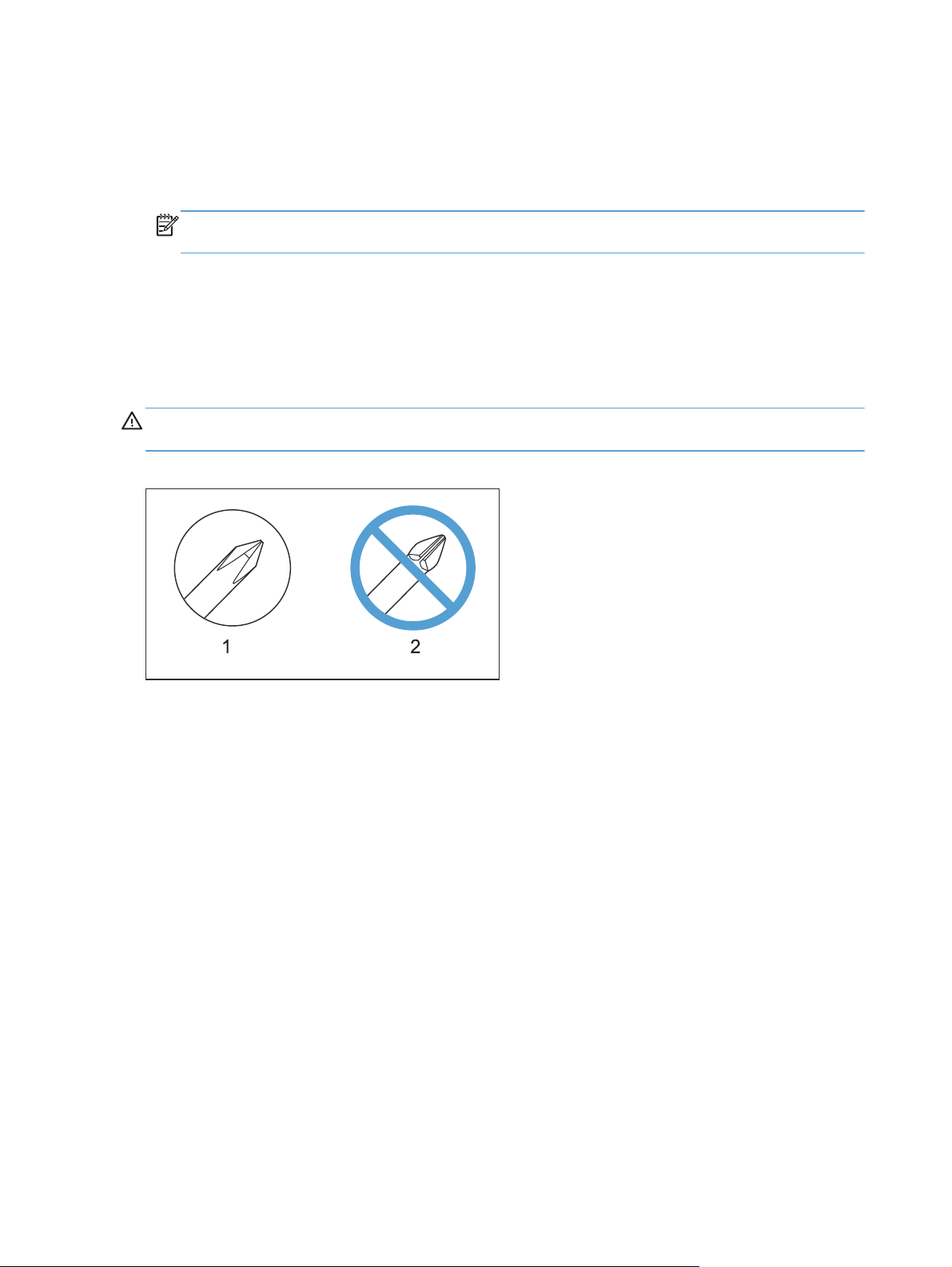
Figure 1-1 Phillips and pozidrive screwdriver comparison .......................................................................... 4
Figure 1-2 Parts removal order (1 of 2) .................................................................................................... 7
Figure 1-3 Parts removal order (2 of 2) .................................................................................................... 7
Figure 1-4 Remove the Tray 2 cassette ..................................................................................................... 8
Figure 1-5 Remove the pickup roller (1 of 2) ........................................................................................... 11
Figure 1-6 Remove the pickup roller (2 of 2) ........................................................................................... 11
Figure 1-7 Remove the separation roller (1 of 3) ..................................................................................... 12
Figure 1-8 Remove the separation roller (2 of 3) ..................................................................................... 13
Figure 1-9 Remove the separation roller (3 of 3) ..................................................................................... 13
Figure 1-10 Reinstall the separation roller .............................................................................................. 14
Figure 1-11 Remove the Tray 1 paper-pickup roller (1 of 3) ..................................................................... 16
Figure 1-12 Remove the Tray 1 paper-pickup roller (2 of 3) ..................................................................... 16
Figure 1-13 Remove the Tray 1 paper-pickup roller (3 of 3) ..................................................................... 17
Figure 1-14 Remove the Tray 1 separation pad ...................................................................................... 17
Figure 1-15 Remove the print-cartridge drawer (1 of 3) ........................................................................... 18
Figure 1-16 Remove the print-cartridge drawer (2 of 3) ........................................................................... 18
Figure 1-17 Remove the print-cartridge drawer (3 of 3) ........................................................................... 19
Figure 1-18 Remove the DIMM cover .................................................................................................... 20
Figure 1-19 Remove the right cover (1 of 5) ........................................................................................... 21
Figure 1-20 Remove the right cover (2 of 5) ........................................................................................... 21
Figure 1-21 Remove the right cover (3 of 5) ........................................................................................... 22
Figure 1-22 Remove the right cover (4 of 5) ........................................................................................... 22
Figure 1-23 Remove the right cover (5 of 5) ........................................................................................... 23
Figure 1-24 Reinstall the right cover ...................................................................................................... 23
Figure 1-25 Remove the rear-upper cover (1 of 2) ................................................................................... 24
Figure 1-26 Remove the rear-upper cover (2 of 2) ................................................................................... 24
Figure 1-27 Remove the rear-door stopper and link caps (simplex product) (1 of 2) ..................................... 25
Figure 1-28 Remove the rear-door stopper and link cap (simple
Figure 1-29 Remove the rear door (simplex product) (1 of 4) .................................................................... 26
Figure 1-30 Remove the rear door (simplex product) (2 of 4) .................................................................... 26
Figure 1-31 Remove the rear door (simplex product) (3 of 4) .................................................................... 27
Figure 1-32 Remove the rear door (simplex product) (4 of 4) .................................................................... 27
x product) (2 of 2) ...................................... 25
ENWW xvii
Page 16

Figure 1-33 Remove the rear door (duplex product) (1 of 4) ..................................................................... 28
Figure 1-34 Remove the rear door (duplex product) (2 of 4) ..................................................................... 28
Figure 1-35 Remove the rear door (duplex product) (3 of 4) ..................................................................... 29
Figure 1-36 Remove the rear door (duplex product) (4 of 4) ..................................................................... 29
Figure 1-37 Remove the rear cover and feed guide (simplex product) (1 of 6) ............................................ 30
Figure 1-38 Remove the rear cover and feed guide (simplex product) (2 of 6) ............................................ 31
Figure 1-39 Remove the rear cover and feed guide (simplex product) (3 of 6) ............................................ 31
Figure 1-40 Remove the rear cover and feed guide (simplex product) (4 of 6) ............................................ 32
Figure 1-41 Remove the rear cover and feed guide (simplex product) (5 of 6) ............................................ 33
Figure 1-42 Remove the rear cover and feed guide (simplex product) (6 of 6) ............................................ 33
Figure 1-43 Remove the rear-lower cover and rear-door links (duplex product) (1 of 6) ................................ 34
Figure 1-44 Remove the rear-lower cover and rear-door links (duplex product) (2 of 6) ................................ 35
Figure 1-45 Remove the rear-lower cover and rear-door links (duplex product) (3 of 6) ................................ 35
Figure 1-46 Remove the rear-lower cover and link-guides (duplex product) (4 of 6) ..................................... 36
Figure 1-47 Remove the rear-lower cover and link-guides (duplex product) (5 of 6) ..................................... 36
Figure 1-48 Remove the rear-lower cover and rear-door links (duplex product) (6 of 6) ................................ 37
Figure 1-49 Remove the rear-door rib assembly (duplex product) (1 of 3) .................................................. 38
Figure 1-50 Remove the rear-door rib assembly (duplex product) (2 of 3) .................................................. 39
Figure 1-51 Remove the rear-door rib assembly (duplex product) (3 of 3) .................................................. 39
Figure 1-52 Replace the link guide (simplex products) ............................................................................. 40
Figure 1-53 Replace the link guide (duplex products) .............................................................................. 40
Figure 1-54 Remove the upper-cover assembly (1 of 4) ............................................................................ 41
Figure 1-55 Remove the upper-cover assembly (2 of 4) ............................................................................ 41
Figure 1-56 Remove the upper-cover assembly (3 of 4) ............................................................................ 42
Figure 1-57 Remove the upper-cover assembly (4 of 4) ............................................................................ 42
Figure 1-58 Upper-cover tabs correctly seated ........................................................................................ 43
Figure 1-59 Upper-cover tabs
Figure 1-60 Remove the left cover (1 of 3) ............................................................................................. 44
Figure 1-61 Remove the left cover (2 of 3) ............................................................................................. 45
Figure 1-62 Remove the left cover (3 of 3) ............................................................................................. 45
Figure 1-63 Reinstall the left cover (1 of 2) ............................................................................................. 46
Figure 1-64 Reinstall the left cover (2 of 2) ............................................................................................. 46
Figure 1-65 Remove the right-front cover and power button (1 of 2) .......................................................... 47
Figure 1-66 Remove the right-front cover and power button (2 of 2) .......................................................... 48
Figure 1-67 Remove the feed assembly (1 of 2) ...................................................................................... 48
Figure 1-68 Remove the feed assembly (2 of 2) ...................................................................................... 49
Figure 1-69 Remove the control-panel assembly (1 of 3) .......................................................................... 50
Figure 1-70 Remove the control-panel assembly (2 of 3) .......................................................................... 51
Figure 1-71 Remove the control-panel assembly (3 of 3) .......................................................................... 51
Figure 1-72 Remove the right panel (1 of 8) ........................................................................................... 52
Figure 1-73 Remove the right panel (2 of 8) ........................................................................................... 53
not
correctly seated .................................................................................. 43
xviii ENWW
Page 17

Figure 1-74 Remove the right panel (3 of 8) ........................................................................................... 53
Figure 1-75 Remove the right panel (4 of 8) ........................................................................................... 54
Figure 1-76 Remove the right panel (5 of 8) ........................................................................................... 54
Figure 1-77 Remove the right panel (6 of 8) ........................................................................................... 55
Figure 1-78 Remove the right panel (7 of 8) ........................................................................................... 55
Figure 1-79 Remove the right panel (8 of 8) ........................................................................................... 56
Figure 1-80 Remove the front-door assembly (1 of 10) ............................................................................. 57
Figure 1-81 Remove the front-door assembly (2 of 10) ............................................................................. 58
Figure 1-82 Remove the front-door assembly (3 of 10) ............................................................................. 58
Figure 1-83 Remove the front-door assembly (4 of 10) ............................................................................. 59
Figure 1-84 Remove the front-door assembly (5 of 10) ............................................................................. 59
Figure 1-85 Remove the front-door assembly (6 of 10) ............................................................................. 60
Figure 1-86 Remove the front-door assembly (7 of 10) ............................................................................. 60
Figure 1-87 Remove the front-door assembly (8 of 10) ............................................................................. 61
Figure 1-88 Remove the front-door assembly (9 of 10) ............................................................................. 61
Figure 1-89 Remove the front-door assembly (10 of 10) ........................................................................... 62
Figure 1-90 Reinstall the front-door assembly (1 of 2) .............................................................................. 62
Figure 1-91 Reinstall the front-door assembly (2 of 2) .............................................................................. 63
Figure 1-92 Remove the ITB (1 of 6) ...................................................................................................... 64
Figure 1-93 Remove the ITB (2 of 6) ...................................................................................................... 64
Figure 1-94 Remove the ITB (3 of 6) ...................................................................................................... 65
Figure 1-95 Remove the ITB (4 of 6) ...................................................................................................... 65
Figure 1-96 Remove the ITB (5 of 6) ...................................................................................................... 66
Figure 1-97 Remove the ITB (6 of 6) ...................................................................................................... 66
Figure 1-98 Reinstall the ITB ................................................................................................................. 67
Figure 1-99 Remove motor M1 or motor M2 (1 of 5) .............................................................................. 68
Figure 1-100 Remove motor M1 and motor M2 (2 of 5) .......................................................................... 69
Figure 1-101 Remove motor M1 and motor M2 (3 of 5) .......................................................................... 69
Figure 1-102 Re
Figure 1-103 Remove motor M1 and motor M2 (5 of 5) .......................................................................... 70
Figure 1-104 Reinstall the motor M1 and motor M2 wire-harness retainer .................................................. 71
Figure 1-105 Remove the Intermediate PCA (1 of 2) ................................................................................ 72
Figure 1-106 Remove the Intermediate PCA (2 of 2) ................................................................................ 73
Figure 1-107 Remove the formatter PCA (1 of 2) .................................................................................... 75
Figure 1-108 Remove the formatter PCA (2 of 2) .................................................................................... 75
Figure 1-109 Remove the DC controller PCA (1 of 2) .............................................................................. 77
Figure 1-110 Remove the DC controller PCA (2 of 2) .............................................................................. 77
Figure 1-111 Remove the fuser motor assembly (1 of 4) ........................................................................... 78
Figure 1-112 Remove the fuser motor assembly (2 of 4) ........................................................................... 79
Figure 1-113 Remove the fuser motor assembly (3 of 4) ........................................................................... 79
Figure 1-114 Remove the fuser motor assembly (4 of 4) ........................................................................... 80
move motor M1 and motor M2 (4 of 5) .......................................................................... 70
ENWW xix
Page 18

Figure 1-115 Reinstall the fuser motor assembly ...................................................................................... 80
Figure 1-116 Remove the high-voltage power-supply PCA (1 of 5) ............................................................ 81
Figure 1-117 Remove the high-voltage power-supply PCA (2 of 5) ............................................................ 82
Figure 1-118 Remove the high-voltage power-supply PCA (3 of 5) ............................................................ 82
Figure 1-119 Remove the high-voltage power-supply PCA (4 of 5) ............................................................ 83
Figure 1-120 Remove the high-voltage power-supply PCA (5 of 5) ............................................................ 83
Figure 1-121 Remove the color-misregistration sensor assembly PCA (1 of 4) ............................................. 84
Figure 1-122 Remove the color-misregistration sensor assembly PCA (2 of 4) ............................................. 85
Figure 1-123 Remove the color-misregistration sensor assembly PCA (3 of 4) ............................................. 85
Figure 1-124 Remove the color-misregistration sensor assembly PCA (4 of 4) ............................................. 86
Figure 1-125 Reinstall the color-misregistration sensor assembly PCA (1 of 2) ............................................. 86
Figure 1-126 Reinstall the color-misregistration sensor assembly PCA (2 of 2) ............................................. 87
Figure 1-127 Remove the fan (1 of 2) .................................................................................................... 88
Figure 1-128 Remove the fan (2 of 2) .................................................................................................... 88
Figure 1-129 Remove the duplex reverse-drive assembly (1 of 4) .............................................................. 89
Figure 1-130 Remove the duplex reverse-drive assembly (2 of 4) .............................................................. 90
Figure 1-131 Remove the duplex reverse-drive assembly (3 of 4) .............................................................. 90
Figure 1-132 Remove the duplex reverse-drive assembly (4 of 4) .............................................................. 91
Figure 1-133 Remove the fuser (1 of 8) ................................................................................................. 92
Figure 1-134 Remove the fuser (2 of 8) ................................................................................................. 93
Figure 1-135 Remove the fuser (3 of 8) ................................................................................................. 93
Figure 1-136 Remove the fuser (4 of 8) ................................................................................................. 94
Figure 1-137 Remove the fuser (5 of 8) ................................................................................................. 94
Figure 1-138 Remove the fuser (6 of 8) ................................................................................................. 95
Figure 1-139 Remove the fuser (7 of 8) ................................................................................................. 95
Figure 1-140 Remove the fuser (8 of 8) ................................................................................................. 96
Figure 1-141 Reinstall the fuser ............................................................................................................. 97
Figure 1-142 Remove the paper-delivery assembly (1 of 4) ...................................................................... 98
Figure 1-143 Remove the paper-delivery assembly (2 of 4) ...................................................................... 99
Figure 1-144 Remove the paper-delivery assembly (3 of 4) ...................................................................... 99
Figure 1-145 Remove the paper-delivery assembly (4 of 4) .................................................................... 100
Figure 2-1 Engine test button location .................................................................................................. 106
Figure 2-2 DC controller connectors .................................................................................................... 107
Figure 2-
Figure 2-4 Solenoid, clutches, and sensors ........................................................................................... 109
Figure 2-5 Rollers .............................................................................................................................. 111
Figure 2-6 Motors and fans ................................................................................................................ 112
Figure 2-7 PCAs ............................................................................................................................... 113
Figure 2-8 Timing diagram ................................................................................................................. 114
Figure 2-9 Circuit diagram ................................................................................................................. 115
Figure 2-10 CPU diagram ................................................................................................................. 116
3 Major components ............................................................................................................ 108
xx ENWW
Page 19

Figure 2-11 ASIC diagram ................................................................................................................. 117
Figure 2-12 HVT/Toner EMP diagram ................................................................................................. 118
Figure 2-13 Driver PCA diagram ........................................................................................................ 119
Figure 2-14 Duplexer PCA diagram .................................................................................................... 120
Figure 2-15 FSR diagram ................................................................................................................... 121
Figure 3-1 Covers, panels, and doors ................................................................................................. 182
Figure 3-2 Internal assemblies (1 of 7) ................................................................................................. 184
Figure 3-3 Internal assemblies (2 of 7) ................................................................................................. 186
Figure 3-4 Internal assemblies (3 of 7) ................................................................................................. 188
Figure 3-5 Internal assemblies (4 of 7) ................................................................................................. 190
Figure 3-6 Internal assemblies (5 of 7) ................................................................................................. 192
Figure 3-7 Internal assemblies (simplex models) .................................................................................... 194
Figure 3-8 Internal assemblies (duplex models) ..................................................................................... 196
Figure 3-9 PCAs ............................................................................................................................... 198
Figure 3-10 250-sheet paper feeder (optional Tray 3) ........................................................................... 200
ENWW xxi
Page 20

1 Removal and replacement
Removal and replacement strategy
●
Service approach
●
Removal and replacement procedures
●
ENWW 1
Page 21

Removal and replacement strategy
This chapter describes the removal and replacement of field-replaceable units (FRUs) only.
Replacing FRUs is generally the reverse of removal procedures. Occasionally, notes and tips are
included to provide directions for difficult or critical replacement procedures.
not
HP does
Note the length, diameter, color, type, and location of each screw. Be sure to return each screw to its
original location during reassembly.
Incorrectly routed or loose wire harnesses can interfere with other internal components and can become
damaged or broken. Frayed or pinched harness wires can be difficult to find. When replacing wire
harnesses, always use the provided wire loops, lance points, or wire-harness guides.
Introduction
This chapter describes the removal and replacement of field-replaceable units (FRUs) only.
Replacing FRUs is generally the reverse of removal. Occasionally, notes and tips are included to
provide directions for difficult or critical replacement procedures.
HP does
support repairing individual subassemblies or troubleshooting to the component level.
not
support repairing individual subassemblies or troubleshooting to the component level.
Note the length, diameter, color, type, and location of each screw. Be sure to return each screw to its
original location during reassembly.
Incorrectly routed or loose wire harnesses can interfere with other internal components and can become
damaged or broken. Frayed or pinched harness wires can be difficult to find. When replacing wire
harnesses, always use the provided wire loops, lance points, or wire-harness guides and retainers.
Removal and replacement strategy
WARNING! Turn the product off, wait 5 seconds, and then remove the power cord before attempting
to service the product. If this warning is not followed, severe injury can result, in addition to damage to
the product. The power must be on for certain functional checks during troubleshooting. However,
disconnect the power supply during parts removal.
Never operate or service the product with the protective cover removed from the laser/scanner
assembly. The reflected beam, although invisible, can damage your eyes.
The sheet-metal parts can have sharp edges. Be careful when handling sheet-metal parts.
CAUTION: Do not bend or fold the flat flexible cables (FFCs) during removal or installation. Also, do
not straighten pre-folds in the FFCs. You
an FFC into a connector can cause a short circuit in a PCA.
NOTE: To install a self-tapping screw, first turn it counterclockwise to align it with the existing thread
pattern, and then carefully turn it clockwise to tighten. Do not overtighten. If a self-tapping screw-hole
becomes stripped, repair the screw-hole or replace the affected assembly.
must
fully seat all FFCs in their connectors. Failure to fully seat
2 Chapter 1 Removal and replacement ENWW
Page 22

TIP: For clarity, some photos in this chapter show components removed that would not be removed to
service the product. If necessary, remove the components listed at the beginning of a procedure before
proceeding to service the product.
Electrostatic discharge
CAUTION: Some parts are sensitive to electrostatic discharge (ESD). Look for the ESD reminder
when removing product parts. Always perform service work at an ESD-protected workstation or mat, or
use an ESD strap. If an ESD workstation, mat, or strap is not available, ground yourself by touching the
sheet-metal chassis
Protect the ESD-sensitive parts by placing them in ESD pouches when they are out of the product.
before
touching an ESD-sensitive part.
ENWW
Removal and replacement strategy
3
Page 23
Required tools
#2 Phillips screwdriver with a magnetic tip and a 152-mm (6-inch) shaft length
●
Precision, slotted screwdriver with a 1 mm (0.04 in) blade width
●
NOTE: This fine-point tool is required to release the front-door pins. The width of the blade must
be 2 mm (0.08 in) or less to be able to push the door pins out of the mounting holes.
Small, slotted screwdriver
●
Needle-nose pliers
●
ESD mat (if one is available)
●
Penlight (optional)
●
CAUTION: Always use a Phillips screwdriver (callout 1). Do not use a pozidrive screwdriver
(callout 2) or any motorized screwdriver. These can damage screws or screw threads.
Figure 1-1 Phillips and pozidrive screwdriver comparison
4 Chapter 1 Removal and replacement ENWW
Page 24
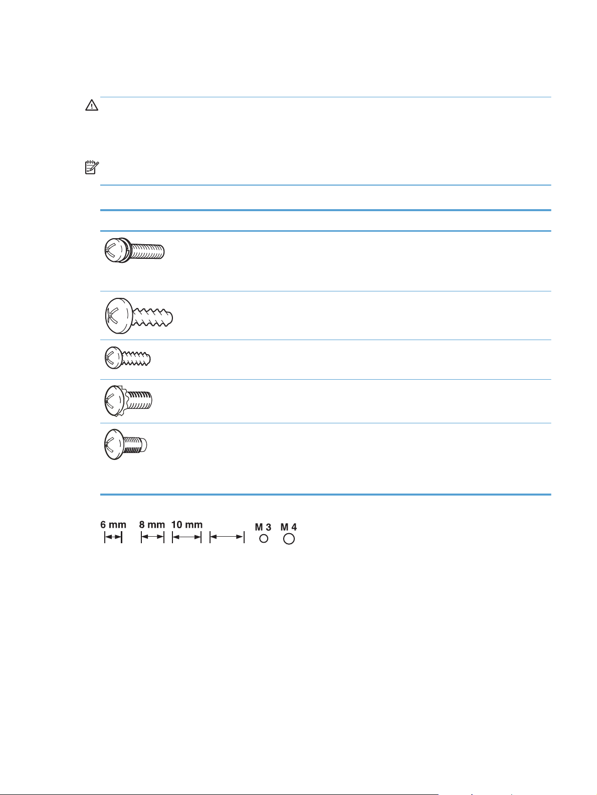
Types of screws
12 mm
WARNING! Make sure that components are replaced with the correct screw type. Using the incorrect
screw (for example, substituting a long screw for the correct shorter screw) can cause damage to the
product or interfere with product operation. Do not intermix screws that are removed from one
component with the screws that are removed from another component.
NOTE: The screw illustrations in the following table are for reference only. Screws might vary in size
and appearance from those shown in this table.
Table 1-1 Common fasteners
Example Description Size Part Number
Screw, with washer M3X8
M4X6
M4X12
Screw, tapping, truss head M4X10
M4X15
Screw, TP M3X4
M3X6
Screw, D M3X6
M3X8
Screw, machine
Screw, machine, flat head
Screw, machine, flanged pan
head
M3X4
M3X4
M3X6
12 mm
XA9-1420-000CN
XB2-7400-605CN
XA9-1422-000CN
XB4-7401-005CN
XB4-7401-609CN
XB6-7300-405CN
XB6-7300-605CN
XA9-1670-000CN
XA9-1671-000CN
XB6-7300-409CN
XA9-0679-000CN
XB6-7300-805CN
ENWW
Removal and replacement strategy
5
Page 25

Service approach
Before performing service
Remove all media from the product.
●
Turn off the power using the power button.
●
Unplug the power cable and interface cable or cables.
●
Place the product on an ESD mat (if available). If an ESD workstation or mat is not available,
●
ground yourself by touching the sheet-metal chassis
Remove the toner cartridges.
●
Remove the Tray 2 cassette.
●
After performing service
Connect the interface cables, and then plug in the power cable.
●
Reinstall the toner cartridges.
●
Reinstall the Tray 2 cassette.
●
before
touching an ESD-sensitive part.
Post-service test
After service has been completed, perform the following test to verify that the repair or replacement
was successful.
Print-quality test
1. Verify that you have completed the necessary reassembly steps.
2. Make sure that the input tray contains clean, unmarked paper.
3. Attach the power cord and interface cable, and then turn on the product.
4. Verify that the expected startup sounds occur.
5. Print a configuration page, and then verify that the expected printing sounds occur.
6. Use the control-panel menus to calibrate the product.
7. Print a diagnostic page, and then verify that the print quality is as expected.
8. Send a print job from the host computer, and then verify that the output meets expectations.
9. If necessary, restore any customer-specified settings.
10. Clean the outside of the product with a damp cloth.
6 Chapter 1 Removal and replacement ENWW
Page 26

Parts removal order
Figure 1-2 Parts removal order (1 of 2)
Figure 1-3 Parts removal order (2 of 2)
ENWW
Service approach
7
Page 27

Removal and replacement procedures
Tray 2 cassette
Pull the tray straight out of the product to remove it.
Figure 1-4 Remove the Tray 2 cassette
8 Chapter 1 Removal and replacement ENWW
Page 28

Rollers and pads
Replace the transfer roller
The transfer roller is a component of the paper-feed assembly and not available as an individual part.
To remove and replace the transfer roller, install a replacement paper-feed assembly. See
guide assembly on page 48.
Paper-feed
ENWW
Removal and replacement procedures
9
Page 29

Replace the pickup roller
The roller must be rotated into the service position to remove it.
CAUTION: Avoid touching the spongy roller surface unless you are going to replace the roller. Skin
oils on the roller can cause paper-pickup problems.
1. Turn the product on, and wait for it to reach the Ready state. Perform the following steps to rotate
the roller to the service position.
NOTE: If you have removed Tray 2 to service the product, reinstall the tray before turning the
product on.
TIP: The following steps rotate the engine paper-pickup roller
into the service position.
a. Open the 2ndry Service menu by pressing the Left Arrow button and the Cancel button
simultaneously.
b. Use the arrow buttons to select Pick roller, and then press the OK button.
Press the OK button again to confirm that you want the roller to rotate.
c. Listen for the roller to rotate. When the roller is done rotating, unplug the power cord, and
then place the power button in the off position.
CAUTION: It is important to place the power button in the off position
power cord so that the product power does not come on immediately when the power cord is
plugged in again.
d. Remove Tray 2.
e. Perform the remaining steps in this procedure to remove the roller. After replacing the roller,
plug the power cord into the product, and then use the power button to turn the product on.
and
the Tray 1 paper-pickup roller
after
unplugging the
10 Chapter 1 Removal and replacement ENWW
Page 30
2. Carefully raise the front of the product.
WARNING! Do not place the product face-up resting on the rear cover and rear door. Excess
toner might enter the laser/scanner assembly and contaminate the mirrors, causing print-quality
problems. The laser/scanner is not a FRU. If the laser/scanner mirrors are contaminated, the entire
product must be replaced.
CAUTION: Do not lift the product by grasping the front door and Tray 2 cavity.
NOTE: The roller is located inside the tray cavity.
Figure 1-5 Remove the pickup roller (1 of 2)
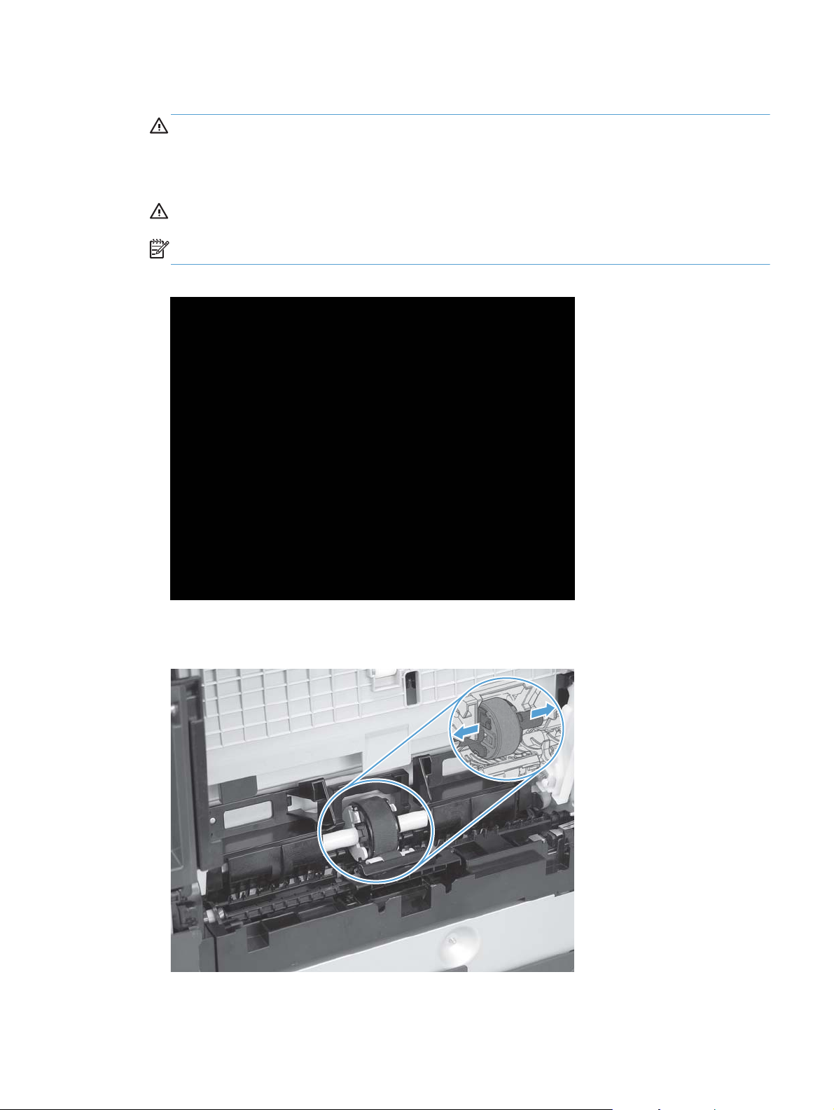
3. Release the two white plastic locking tabs and remove the pickup roller.
Figure 1-6 Remove the pickup roller (2 of 2)
ENWW
Removal and replacement procedures
11
Page 31

Repalce the separation roller
CAUTION: Avoid touching the spongy roller surface unless you are going to replace the roller. Skin
oils on the roller can cause paper-pickup problems.
1. Remove Tray 2 (if installed), and then carefully raise the front of the product.
WARNING! Do not place the product face-up resting on the rear cover and rear door. Excess
toner might enter the laser/scanner assembly and contaminate the mirrors, causing print-quality
problems. The laser/scanner is not a FRU. If the laser/scanner mirrors are contaminated, the entire
product must be replaced.
CAUTION: Do not lift the product by grasping the front door and Tray 2 cavity.
NOTE: The roller is located inside the tray cavity.
Figure 1-7 Remove the separation roller (1 of 3)
12 Chapter 1 Removal and replacement ENWW
Page 32

2. Release the two roller-cover locking pins, and then remove the cover.
Figure 1-8 Remove the separation roller (2 of 3)
3. Release the roller holder to release the roller-locking pins. Remove the separation roller.
Figure 1-9 Remove the separation roller (3 of 3)
ENWW
Removal and replacement procedures
13
Page 33

Reinstall the separation roller
1. Install the replacement separation roller.
2. Reinstall the separation roller cover on the locking pins, and then rotate it toward the roller until
you hear it snap into place.
Figure 1-10 Reinstall the separation roller
14 Chapter 1 Removal and replacement ENWW
Page 34

Replace the pickup roller and separation pad (Tray 1)
The roller must be rotated into the service position to remove it.
CAUTION: Avoid touching the spongy roller surface unless you are going to replace the roller. Skin
oils on the roller can cause paper pickup problems.
NOTE: Always replace the separation pad when replacing the paper-pickup roller.
1. Turn the product on, and wait for it to reach the Ready state. Perform the following steps to rotate
the roller to the service position.
NOTE: If you have removed Tray 2 to service the product, reinstall the tray before turning the
product on.
TIP: The following steps rotate the engine paper-pickup roller
into the service position.
a. Open the 2ndry Service menu by pressing the Left Arrow button and the Cancel button
simultaneously.
b. Use the arrow buttons to select Pick roller, and then press the OK button.
Press the OK button again to confirm that you want the roller to rotate.
c. Listen for the roller to rotate. When the roller is done rotating, unplug the power cord, and
then place the power button in the off position.
CAUTION: It is important to place the power button in the off position
power cord so that the product power does not come on immediately when the power cord is
plugged in again.
d. Remove Tray 2.
e. Perform the remaining steps in this procedure to remove the roller. After replacing the roller,
plug the power cord into the product, and then use the power button to turn the product on.
and
the Tray 1 paper-pickup roller
after
unplugging the
ENWW
Removal and replacement procedures
15
Page 35

2. Lower the Tray 1 paper-pickup assembly by pushing down on the edges of the assembly.
Figure 1-11 Remove the Tray 1 paper-pickup roller (1 of 3)
3. Carefully raise the front of the product.
WARNING! Do not place the product face-up resting on the rear cover and rear door. Excess
toner might enter the laser/scanner assembly and contaminate the mirrors, causing print-quality
problems. The laser/scanner is not a FRU. If the laser/scanner mirrors are contaminated, the entire
product must be replaced.
Figure 1-12 Remove the Tray 1 paper-pickup roller (2 of 3)
16 Chapter 1 Removal and replacement ENWW
Page 36

4. Release two tabs, and then rotate the roller away from the product to remove it.
Figure 1-13 Remove the Tray 1 paper-pickup roller (3 of 3)
5. Release the retainer tabs, and then remove the separation pad from the base.
CAUTION: The Tray 1 separation-pad spring is not captive. Do not lose the spring when the
separation pad is removed.
Figure 1-14 Remove the Tray 1 separation pad
ENWW
Removal and replacement procedures
17
Page 37

Main assemblies
Print-cartridge drawer
1. Open the front door.
2. Partially pull out the print-cartridge drawer, and then use a small, flat-blade screwdriver to release
one tab (callout 1) on the left side of the product.
Figure 1-15 Remove the print-cartridge drawer (1 of 3)
1
3. Carefully rotate the print-cartridge drawer toward the right side of the product to release it.
Figure 1-16 Remove the print-cartridge drawer (2 of 3)
18 Chapter 1 Removal and replacement ENWW
Page 38

4. Pull the print-cartridge drawer out of the product to remove it.
Figure 1-17 Remove the print-cartridge drawer (3 of 3)
ENWW
Removal and replacement procedures
19
Page 39

DIMM cover
1. Open the DIMM cover.
2. Lift the cover up to release it, and then remove the cover.
Figure 1-18 Remove the DIMM cover
20 Chapter 1 Removal and replacement ENWW
Page 40

Right cover
1. Remove the DIMM cover. See DIMM cover on page 20.
2. Open the rear cover, and then remove three screws (callout 1).
Figure 1-19 Remove the right cover (1 of 5)
1
3. Before you proceed, take note of the mounting tab locations on the back of the cover.
Figure 1-20 Remove the right cover (2 of 5)
ENWW
Removal and replacement procedures
21
Page 41

4. Slide the right cover toward the back of the product.
Figure 1-21 Remove the right cover (3 of 5)
5. Release one tab (callout 1).
Figure 1-22 Remove the right cover (4 of 5)
1
22 Chapter 1 Removal and replacement ENWW
Page 42

6. Remove the right cover.
Figure 1-23 Remove the right cover (5 of 5)
Reinstall the right cover
NOTE: Do not reinstall the DIMM cover before reinstalling the right cover. The cover will interfere with
the product chassis and prevent the correct installation of the right cover.
Before you reinstall the right cover, take note of the mounting tab locations on the back of the
●
cover.
Figure 1-24 Reinstall the right cover
ENWW
Removal and replacement procedures
23
Page 43

Rear-upper cover (duplex product)
1. Open the rear cover.
2. Remove two screws (callout 1).
Figure 1-25 Remove the rear-upper cover (1 of 2)
1
3. Slightly separate the cover from the product, and rotate the cover down and then away from the
product to remove it.
Figure 1-26 Remove the rear-upper cover (2 of 2)
24 Chapter 1 Removal and replacement ENWW
Page 44

Rear-door stopper and link caps (simplex product)
1. Open the rear door.
2. Use a pair of needle-nose pliers to release two tabs, and then remove the link cap.
TIP: It might be easier to remove the link caps if you remove the feed assembly. See Paper-feed
guide assembly on page 48.
Figure 1-27 Remove the rear-door stopper and link caps (simplex product) (1 of 2)
3. Use a small, flat-blade screwdriver to carefully remove the remaining link cap, and then remove
the rear-door stopper.
Figure 1-28 Remove the rear-door stopper and link cap (simplex product) (2 of 2)
ENWW
Removal and replacement procedures
25
Page 45

Rear door (simplex product)
1. Open the rear door.
2. Use a pair of needle-nose pliers to release two tabs, and then remove the link cap.
TIP: It might be easier to remove the link cap if you remove the feed assembly. See Paper-feed
guide assembly on page 48.
Figure 1-29 Remove the rear door (simplex product) (1 of 4)
3. Remove four screws (callout 1).
Figure 1-30 Remove the rear door (simplex product) (2 of 4)
1
26 Chapter 1 Removal and replacement ENWW
Page 46

4. Before you remove the rear door, take note of the alignment pins on the door.
Figure 1-31 Remove the rear door (simplex product) (3 of 4)
5. Remove the rear door.
Figure 1-32 Remove the rear door (simplex product) (4 of 4)
ENWW
Removal and replacement procedures
27
Page 47

Rear door (duplex product)
1. Open the rear door.
2. Use the green handle to close the duplex-feed assembly.
Figure 1-33 Remove the rear door (duplex product) (1 of 4)
3. Remove two screws (callout 1).
Figure 1-34 Remove the rear door (duplex product) (2 of 4)
1
28 Chapter 1 Removal and replacement ENWW
Page 48

4. Before you remove the rear door, take note of the mounting tabs on the door.
Figure 1-35 Remove the rear door (duplex product) (3 of 4)
5. Slide the door away from the product to release two tabs, and then remove the door.
Figure 1-36 Remove the rear door (duplex product) (4 of 4)
ENWW
Removal and replacement procedures
29
Page 49

Rear cover and feed guide (simplex product)
Before proceeding, remove the following components:
Rear-door stopper. See
●
Rear door. See
●
Right cover. See
●
Remove the rear cover and feed guide (simplex product)
1. Carefully release the link guide from the pivot pin on the feed guide.
Figure 1-37 Remove the rear cover and feed guide (simplex product) (1 of 6)
Rear door (simplex product) on page 26.
Rear-door stopper and link caps (simplex product) on page 25.
Right cover on page 21.
30 Chapter 1 Removal and replacement ENWW
Page 50

2. Remove three screws (callout 1).
Figure 1-38 Remove the rear cover and feed guide (simplex product) (2 of 6)
1
3. Release two tabs (callout 1).
Figure 1-39 Remove the rear cover and feed guide (simplex product) (3 of 6)
1
ENWW
Removal and replacement procedures
31
Page 51

4. Carefully lift the cover up, and then rotate it away from the product to remove it.
Figure 1-40 Remove the rear cover and feed guide (simplex product) (4 of 6)
2
2
1
Reinstallation tip Make sure that the wire harnesses at the top of the chassis near the left-side
cover are correctly retained so that they are not pinched when the rear cover is reinstalled.
32 Chapter 1 Removal and replacement ENWW
Page 52

5. Carefully release a feed-guide hinge pin from the rear cover to release the feed guide.
Figure 1-41 Remove the rear cover and feed guide (simplex product) (5 of 6)
6. Remove the feed guide.
Figure 1-42 Remove the rear cover and feed guide (simplex product) (6 of 6)
ENWW
Removal and replacement procedures
33
Page 53

Rear-lower cover and rear-door links (duplex product)
Before proceeding, remove the following components:
Right cover. See
●
Rear-upper cover. See
●
Rear door. See
●
Remove the rear-lower cover and rear-door links (duplex product)
1. Use a pair of needle-nose pliers to release two tabs, and then remove the rear-door link cap.
Repeat this step for the remaining rear-door link cap.
Figure 1-43 Remove the rear-lower cover and rear-door links (duplex product) (1 of 6)
Right cover on page 21.
Rear-upper cover (duplex product) on page 24.
Rear door (duplex product) on page 28.
34 Chapter 1 Removal and replacement ENWW
Page 54

2. Open the duplex-feed assembly, release one tab (callout 1), and then slightly separate the cover
from the product.
Figure 1-44 Remove the rear-lower cover and rear-door links (duplex product) (2 of 6)
1
3. Release one tab (callout 1) and slightly separate the cover from the product.
Figure 1-45 Remove the rear-lower cover and rear-door links (duplex product) (3 of 6)
1
ENWW
Removal and replacement procedures
35
Page 55

4. Close the duplex assembly, lift up on one side of the cover, and then lift up the other side of the
cover to release it.
Figure 1-46 Remove the rear-lower cover and link-guides (duplex product) (4 of 6)
5. Slightly lift up the rear-door rib assembly, and then carefully slide the cover away from the product
to remove it.
Figure 1-47 Remove the rear-lower cover and link-guides (duplex product) (5 of 6)
36 Chapter 1 Removal and replacement ENWW
Page 56

6. Rotate the rear-door link until the slot in the link aligns with the tap on the link-hinge pin, and then
remove the rear-door link. Repeat this step for the remaining rear-door link.
NOTE: If you are installing a replacement rear-lower cover, remove the rear-door links from the
discarded cover, and then install them on the replacement cover.
Figure 1-48 Remove the rear-lower cover and rear-door links (duplex product) (6 of 6)
ENWW
Removal and replacement procedures
37
Page 57

Rear-door rib assembly (duplex product)
Before proceeding, remove the following components:
Right cover. See
●
Rear-upper cover. See
●
Rear door. See
●
Rear-lower cover. See
●
Remove the rear-door rib assembly (duplex product)
NOTE: The duplex fan (FM2) is a component of the rear-door rib assembly.
1. Disconnect one connector (callout 1).
TIP: The PCA can be dislodged when disconnecting the connector. To secure the PCA, carefully
push it towards the inside of the product to clear the mounting tabs near the rib assembly. Slide
the PCA towards the rib assembly to position the edge of the PCA under the mounting tabs.
Figure 1-49 Remove the rear-door rib assembly (duplex product) (1 of 3)
Right cover on page 21.
Rear-upper cover (duplex product) on page 24.
Rear door (duplex product) on page 28.
Rear-lower cover and rear-door links (duplex product) on page 34.
38 Chapter 1 Removal and replacement ENWW
Page 58

2. Slide the assembly toward the power cord side of the product to release the hinge pin.
Figure 1-50 Remove the rear-door rib assembly (duplex product) (2 of 3)
3. Remove the assembly.
Figure 1-51 Remove the rear-door rib assembly (duplex product) (3 of 3)
ENWW
Removal and replacement procedures
39
Page 59

Link guide
The link guide rarely fails and is not a FRU.
The link is attached to the paper guide (callout 1) and the rear door (simplex products; callout 2) or
duplexing feed guide assembly (duplex products; callout 3).
If the link-guide attachment at the rear door or duplexing feed guide assembly fails, replace the
appropriate component.
The interior paper guide is not replaceable. If the link guide to paper guide attachment fails, you must
replace the entire product.
Figure 1-52 Replace the link guide (simplex products)
1
2
Figure 1-53 Replace the link guide (duplex products)
3
40 Chapter 1 Removal and replacement ENWW
Page 60

Upper-cover assembly
1. Remove the Rear-upper cover. See Rear-upper cover (duplex product) on page 24.
2. Remove one screw (callout 1).
Figure 1-54 Remove the upper-cover assembly (1 of 4)
1
3. Release one tab (callout 1).
Figure 1-55 Remove the upper-cover assembly (2 of 4)
1
ENWW
Removal and replacement procedures
41
Page 61

4. Before you proceed, take note of location of the top cover tabs.
Figure 1-56 Remove the upper-cover assembly (3 of 4)
5. Carefully rotate the back side of the top cover up and off of the product to release the tabs, and
then remove the cover.
NOTE: When you reinstall the upper cover, ensure that all the mounting tabs are correctly
seated. See
Figure 1-57 Remove the upper-cover assembly (4 of 4)
Reinstall the upper cover on page 43.
42 Chapter 1 Removal and replacement ENWW
Page 62

Reinstall the upper cover
When you reinstall the upper cover, ensure that the two tabs in the paper delivery area are fully
●
seated into the chassis.
Figure 1-58 Upper-cover tabs correctly seated
Figure 1-59 Upper-cover tabs
not
correctly seated
ENWW
Removal and replacement procedures
43
Page 63

Left cover
Before proceeding, remove the following components:
Right cover. See
●
Rear cover (simplex products). See
●
Rear-lower cover (duplex products). See
●
Upper-cover assembly. See
●
Remove the left cover
1. Remove one screw (callout 1).
Figure 1-60 Remove the left cover (1 of 3)
Right cover on page 21.
Rear cover and feed guide (simplex product) on page 30.
Rear-upper cover (duplex product) on page 24.
Upper-cover assembly on page 41.
1
44 Chapter 1 Removal and replacement ENWW
Page 64

2. Slightly lift up on the cover, and then rotate the top of the cover away from the product.
Figure 1-61 Remove the left cover (2 of 3)
3. Remove the cover.
Figure 1-62 Remove the left cover (3 of 3)
ENWW
Removal and replacement procedures
45
Page 65

Reinstall the left cover
1. When you reinstall the left cover, ensure that the slot in the cover (callout 1) aligns with the tab
(callout 2) on the product.
Figure 1-63 Reinstall the left cover (1 of 2)
2
1
2. When you reinstall the left cover, ensure that the pin on the cover (callout 1) aligns with the slot
(callout 2) in the product.
Figure 1-64 Reinstall the left cover (2 of 2)
4
3
46 Chapter 1 Removal and replacement ENWW
Page 66

Right-front cover and power button
Before proceeding, remove the following components:
Right cover. See
●
Rear-upper cover (duplex products). See
●
Upper-cover assembly. See
●
Control-panel assembly. See
●
Right panel. See
●
Remove the right-front cover and power button
1. Lift up on one tab (callout 1) and then slide the right-front cover toward the top edge of the right
panel to separate the cover from the panel.
Figure 1-65 Remove the right-front cover and power button (1 of 2)
Right cover on page 21.
Upper-cover assembly on page 41.
Right panel on page 52.
Rear-upper cover (duplex product) on page 24.
Control-panel assembly on page 50.
1
ENWW
Removal and replacement procedures
47
Page 67

2. Release two tabs (callout 1), and then remove the power button.
Figure 1-66 Remove the right-front cover and power button (2 of 2)
Paper-feed guide assembly
1
NOTE: A simplex model is shown below. Duplex and simplex models use the same paper-feed guide
assembly, and the removal and replacement processes are identical.
1. Remove one screw (callout 1).
CAUTION: The bushing on this screw is not captive. Do not lose the bushing when the screw is
removed.
Figure 1-67 Remove the feed assembly (1 of 2)
1
48 Chapter 1 Removal and replacement ENWW
Page 68

2. Remove the feed assembly.
CAUTION: Do not touch the black sponge portion of the roller. Skin oils on the roller can cause
print-quality problems.
Reinstallation tip When the feed assembly is correctly reinstalled, the assembly can move in
relation to the door. It should not be secured firmly to the door.
Figure 1-68 Remove the feed assembly (2 of 2)
ENWW
Removal and replacement procedures
49
Page 69

Control-panel assembly
Before proceeding, remove the following components:
Right cover. See
●
Rear-upper cover (duplex products). See
●
Upper-cover assembly. See
●
Remove the control-panel assembly
CAUTION: Do not bend or fold the flat flexible cables (FFCs) during removal or installation. Also, do
not straighten prefolds in the FFCs. You
Failure to fully seat an FFC into a connector can cause a short circuit in a PCA.
1. Disconnect one FFC (callout 1), and then remove one screw (callout 2).
Figure 1-69 Remove the control-panel assembly (1 of 3)
Right cover on page 21.
1
Rear-upper cover (duplex product) on page 24.
Upper-cover assembly on page 41.
must
ensure that all FFCs are fully seated in their connectors.
2
50 Chapter 1 Removal and replacement ENWW
Page 70

2. Open the front door, and then remove two screws (callout 1).
Figure 1-70 Remove the control-panel assembly (2 of 3)
1
3. Remove the control-panel assembly.
Figure 1-71 Remove the control-panel assembly (3 of 3)
ENWW
Removal and replacement procedures
51
Page 71

Right panel
Before proceeding, remove the following components:
Right cover. See
●
Rear-upper cover (duplex products). See
●
Upper-cover assembly. See
●
Control-panel assembly. See
●
Remove the right panel
1. Disconnect one connector (callout 1; J206) on the DC controller.
Figure 1-72 Remove the right panel (1 of 8)
Right cover on page 21.
Rear-upper cover (duplex product) on page 24.
Upper-cover assembly on page 41.
Control-panel assembly on page 50.
1
52 Chapter 1 Removal and replacement ENWW
Page 72

2. Remove three screws (callout 1).
Figure 1-73 Remove the right panel (2 of 8)
1
3. Remove three screws (callout 1).
Figure 1-74 Remove the right panel (3 of 8)
ENWW
3
Removal and replacement procedures
53
Page 73

4. Disconnect two connectors (callout 1), release the fan wire harness from the guide (callout 2), and
then remove three screws (callout 3).
Figure 1-75 Remove the right panel (4 of 8)
1
23
5. Place the power button in the on position (callout 1).
TIP: When you reinstall the panel, ensure that you place the power button in the off position so
that the product does not immediately turn on when the power cord is plugged into the wall
receptacle.
Figure 1-76 Remove the right panel (5 of 8)
1
54 Chapter 1 Removal and replacement ENWW
Page 74

6. Carefully rotate the back edge of the panel away from the product.
Figure 1-77 Remove the right panel (6 of 8)
7. Carefully push the panel slightly toward the front of the product to release it.
Figure 1-78 Remove the right panel (7 of 8)
ENWW
Removal and replacement procedures
55
Page 75

8. Remove the right panel.
NOTE: If you are replacing the right panel, you must remove the fan and the right-front cover
(the cover includes the power button) from the right panel. See
Fan on page 88 and Right-front
cover and power button on page 47.
Figure 1-79 Remove the right panel (8 of 8)
56 Chapter 1 Removal and replacement ENWW
Page 76

Front-door assembly
Before proceeding, remove the following components:
Print-cartridge drawer. See
●
Right cover. See
●
Upper-cover assembly. See
●
Left cover. See
●
Rear door (simplex products). See
●
Rear cover (simplex products). See
●
Rear-upper cover (duplex products). See
●
Rear door (duplex products). See
●
Rear-lower cover (duplex products). See
●
on page 34.
Control-panel. See
●
Right panel. See
●
Remove the front-door assembly
1. Find the front-door pin on the left-side door link.
Print-cartridge drawer on page 18
Right cover on page 21.
Upper-cover assembly on page 41.
Left cover on page 44.
Rear door (simplex product) on page 26.
Rear cover and feed guide (simplex product) on page 30.
Rear-upper cover (duplex product) on page 24.
Rear door (duplex product) on page 28.
Rear-lower cover and rear-door links (duplex product)
Control-panel assembly on page 50
Right panel on page 52.
Figure 1-80 Remove the front-door assembly (1 of 10)
ENWW
Removal and replacement procedures
57
Page 77

2. Use a precision point screwdriver to push the left-side door pin out of the link.
NOTE: A precision-point screwdriver is required to release the front door pins. The width of the
blade must be 2 mm (0.08 in) or less to be able to push the door pins out of the mounting holes.
Figure 1-81 Remove the front-door assembly (2 of 10)
3. Use a precision-point screwdriver to push the right-side door pin out of the link.
NOTE: A precision point screwdriver is required to release the front door pins. The width of the
blade must be 2 mm (0.08 in) or less to be able to push the door pins out of the mounting holes.
Figure 1-82 Remove the front-door assembly (3 of 10)
58 Chapter 1 Removal and replacement ENWW
Page 78

4. Remove two screws (callout 1) and separate the door bushing (callout 2) from the chassis.
Figure 1-83 Remove the front-door assembly (4 of 10)
2
1
5. Release the bushing from the door-retainer link (callout 1).
Figure 1-84 Remove the front-door assembly (5 of 10)
ENWW
1
Removal and replacement procedures
59
Page 79

6. Support the door assembly, and carefully release the pin on the right-side link.
Figure 1-85 Remove the front-door assembly (6 of 10)
7. Support the door assembly, and carefully release the upper pin on the left-side link.
Figure 1-86 Remove the front-door assembly (7 of 10)
60 Chapter 1 Removal and replacement ENWW
Page 80

8. Push the black-plastic arm into the product.
Figure 1-87 Remove the front-door assembly (8 of 10)
9. Support the door assembly, and carefully release the lower pin on the left-side link.
Figure 1-88 Remove the front-door assembly (9 of 10)
ENWW
Removal and replacement procedures
61
Page 81

10. Remove the front-door assembly.
Figure 1-89 Remove the front-door assembly (10 of 10)
Reinstall the front-door assembly
Use this procedure if you are installing a
1. Open Tray 1, and then rotate the retainer arm until the tabs on the arm-hinge pin align with the
slots in the mounting hole on Tray 1.
Figure 1-90 Reinstall the front-door assembly (1 of 2)
replacement
front-door assembly.
1
62 Chapter 1 Removal and replacement ENWW
Page 82

2. Remove the retainer arm from the door assembly, and then install it on the replacement-door
assembly.
Figure 1-91 Reinstall the front-door assembly (2 of 2)
ENWW
Removal and replacement procedures
63
Page 83

Intermediate transfer belt (ITB)
1. Remove the print-cartridge drawer. See Print-cartridge drawer on page 18.
2. Open the front door, and then remove two screws (callout 1).
Figure 1-92 Remove the ITB (1 of 6)
1
3. Carefully rotate the color misregistration sensor away from the ITB.
CAUTION: The sensor is still attached to the left side of the product and cannot be completely
removed.
Figure 1-93 Remove the ITB (2 of 6)
64 Chapter 1 Removal and replacement ENWW
Page 84

4. Disconnect one connector (callout 1).
Figure 1-94 Remove the ITB (3 of 6)
2
5. Carefully lift up on the front of the ITB to release it.
CAUTION: Avoid touching the black plastic transfer belt. Skin oils on the belt might cause print-
quality problems. Lift the ITB as shown below by using the hard-plastic edges of the ITB.
Figure 1-95 Remove the ITB (4 of 6)
ENWW
Removal and replacement procedures
65
Page 85

6. To release the ITB, you might have to pen the rear door, and carefully lift up on the sheet-metal
portion (callout 1).
CAUTION: Avoid touching the black plastic transfer belt. Skin oils on the belt might cause print-
quality problems.
NOTE: You might need to reach in through the front door and support the front portion of the ITB
to keep it from falling back into place as you perform this step.
Figure 1-96 Remove the ITB (5 of 6)
1
7. Carefully pull the ITB straight out of the product to remove it.
CAUTION: Avoid touching the black plastic transfer belt. Skin oils on the belt might cause print-
quality problems. Handle the ITB as shown below.
Figure 1-97 Remove the ITB (6 of 6)
66 Chapter 1 Removal and replacement ENWW
Page 86

Reinstall the ITB
Use this procedure to verify that the ITB is correctly reinstalled.
1. Use the control panel to print a Diagnostics page. See the complete version of the English service
2. Verify that rows one through four, columns A through I (callout 1) contain hexadecimal numbers.
manual.
If these rows and columns are all zero, ensure that the calibration sensor was correctly reinstalled.
The sensor must be correctly positioned and fit securely against the chassis before the mounting
screws are installed. See
Figure 1-93 Remove the ITB (2 of 6) on page 64 and Figure 1-92
Remove the ITB (1 of 6) on page 64.
Figure 1-98 Reinstall the ITB
HP Color LaserJet PRO 400
Diagnostics Page
Calibration Information
Power-On Calibration : 15 Minutes
Calibration Timing: 48 Hours
Parameters
04
Color Density
C M Y K
Contrast 0 0 0 0
Highlights 0 0 0 0
Midtones 0 0 0 0
Shadows 0 0 0 0
1
ENWW
Removal and replacement procedures
67
Page 87

Drum motor (M1) and developer motor (M2)
This procedure can be used to remove motor M1 or motor M2 separately.
CAUTION: HP does not recommend that you remove or replace both motors at the same time.
1. Remove the right cover. See Right cover on page 21.
2. Disconnect one connector (callout 1) for motor M1 or motor M2.
NOTE: The drum motor (callout 2) is motor M1. The developer motor (callout 3) is motor M2.
Figure 1-99 Remove motor M1 or motor M2 (1 of 5)
1
2
3
68 Chapter 1 Removal and replacement ENWW
Page 88

3. Release the wire harnesses from the retainer (callout 1).
TIP: Additional connectors might need to be disconnected to release the wire harnesses from the
retainer.
Figure 1-100 Remove motor M1 and motor M2 (2 of 5)
1
4. Release one tab (callout 1).
Figure 1-101 Remove motor M1 and motor M2 (3 of 5)
1
ENWW
Removal and replacement procedures
69
Page 89

5. Rotate the top of the retainer away from the chassis, and then lift it up to remove it.
Figure 1-102 Remove motor M1 and motor M2 (4 of 5)
6. Remove three screws (callout 1) to remove motor M1, or remove three screws (callout 2) to remove
motor M2.
Figure 1-103 Remove motor M1 and motor M2 (5 of 5)
1
2
70 Chapter 1 Removal and replacement ENWW
Page 90

Reinstall the drum motor (M1) and developer motor (M2)
When the motor wire harness retainer is reinstalled, the two tabs at the bottom of the retainer must be
positioned behind the retainer on the low-voltage power supply. The tab at the side of motor wire
harness retainer must be positioned behind the PCA next to motor M2.
Figure 1-104 Reinstall the motor M1 and motor M2 wire-harness retainer
ENWW
Removal and replacement procedures
71
Page 91

Intermediate PCA
Before proceeding, remove the following components:
Right cover. See
●
Upper cover. See
●
Right panel. See
●
Remove the intermediate PCA
1. Disconnect all the connectors (callout 1) on the PCA and one FFC (callout 2).
Figure 1-105 Remove the Intermediate PCA (1 of 2)
Right cover on page 21.
Upper-cover assembly on page 41.
Right panel on page 52.
1
2
72 Chapter 1 Removal and replacement ENWW
Page 92

2. Remove three screws (callout 1), and then remove the intermediate PCA.
Figure 1-106 Remove the Intermediate PCA (2 of 2)
1
ENWW
Removal and replacement procedures
73
Page 93

Formatter PCA
Special considerations
WARNING! Do not install a
The formatter PCA and the DC controller PCA store important product configuration information
(NVRAM data) that is lost if both PCAs are replaced at the same time. When the product power is
turned on, the DC controller restores the NVRAM data on the replacement formatter.
Replacing both the formatter and the DC controller at the same time will result in severe print-quality
problems.
NOTE: The base model does not have a fax card installed.
Replacing the formatter PCA before the DC controller PCA
Use the following procedure if you need to install a replacement formatter PCA
controller.
NOTE: If you are only installing a replacement formatter PCA, go to Remove the formatter PCA
on page 74.
1. Install a replacement formatter PCA.
2. Turn the product on, and wait for the print-cartridge volume indicators to appear on the control-
panel display.
NOTE: This allows important product information to be written to the replacement formatter PCA.
replacement
formatter PCA and DC controller PCA at the same time.
and
a replacement DC
3. Turn the product off.
4. Install a replacement DC controller. See
5. Turn the product on.
Remove the formatter PCA
CAUTION: Do not bend or fold the flat flexible cables (FFCs) during removal or installation. Also, do
not straighten prefolds in the FFCs. You
Failure to fully seat an FFC into a connector can cause a short circuit in a PCA.
Some parts are sensitive to electrostatic discharge (ESD). Always perform service work at an ESD-
protected workstation or mat. If an ESD workstation or mat is not available, ground yourself by
touching the sheet-metal chassis
1. Remove the right cover. See Right cover on page 21.
DC controller PCA on page 76.
must
ensure that all FFCs are fully seated in their connectors.
before
touching an ESD-sensitive part.
74 Chapter 1 Removal and replacement ENWW
Page 94

2. Disconnect all the connectors.
Figure 1-107 Remove the formatter PCA (1 of 2)
3. Remove four screws (callout 1), and then remove the formatter PCA.
Figure 1-108 Remove the formatter PCA (2 of 2)
1
ENWW
Removal and replacement procedures
75
Page 95

DC controller PCA
Special considerations
WARNING! Do not install a
same time.
The formatter PCA and the DC controller PCA store important product configuration information
(NVRAM data) that is lost if both PCAs are replaced at the same time. When the product power is
turned on, the formatter restores the NVRAM data to a replacement DC controller.
Replacing both the DC controller and the formatter at the same time will result in severe print-quality
problems.
Replacing the DC controller PCA before the formatter PCA
Use the following procedure if you need to install a replacement DC controller
formatter PCA.
NOTE: If you are only installing a replacement DC controller PCA, go to Remove the DC controller
PCA on page 76.
1. Install a replacement DC controller PCA.
2. Turn the product on, and wait for the print-cartridge volume indicators to appear on the control-
panel display.
NOTE: This allows important product information to be written to the replacement DC controller
PCA.
replacement
formatter PCA and a
replacement
DC controller PCA at the
and
a replacement
3. Turn the product off.
4. Install a replacement formatter PCA. See
5. Turn the product on.
Remove the DC controller PCA
Before proceeding, remove the following components:
Right cover. See
●
Upper cover. See
●
Right panel. See
●
Right cover on page 21.
Upper-cover assembly on page 41.
Right panel on page 52.
Formatter PCA on page 74.
76 Chapter 1 Removal and replacement ENWW
Page 96

CAUTION: Do not bend or fold the flat flexible cables (FFCs) during removal or installation. Also, do
not straighten prefolds in the FFCs. You
Failure to fully seat an FFC into a connector can cause a short circuit in a PCA.
Some parts are sensitive to electrostatic discharge (ESD). Always perform service work at an ESD-
protected workstation or mat. If an ESD workstation or mat is not available, ground yourself by
touching the sheet-metal chassis
1. Disconnect all the connectors.
Figure 1-109 Remove the DC controller PCA (1 of 2)
before
must
ensure that all FFCs are fully seated in their connectors.
touching an ESD-sensitive part.
2. Remove four screws (callout 1) and then remove the DC controller PCA.
Figure 1-110 Remove the DC controller PCA (2 of 2)
1
ENWW
Removal and replacement procedures
77
Page 97

Fuser motor assembly
Before proceeding, remove the following components:
Right cover. See
●
Formatter PCA. See
●
Rear-upper cover (duplex products). See
●
Rear door (simplex products). See
●
Rear cover (simplex products). See
●
Upper-cover assembly. See
●
Control-panel assembly. See
●
Right panel. See
●
Remove the fuser motor assembly
1. Remove four flat-head screws (callout 1), three screws (callout 2), and then remove the sheet-metal
plate.
CAUTION: The four flat-head screws must be installed in the correct position to avoid damage to
the formatter. Standard screws can contact the formatter when it is installed and can cause a
formatter short circuit.
Figure 1-111 Remove the fuser motor assembly (1 of 4)
Right cover on page 21.
Formatter PCA on page 74.
Rear-upper cover (duplex product) on page 24.
Rear door (simplex product) on page 26.
Rear cover and feed guide (simplex product) on page 30.
Upper-cover assembly on page 41.
Control-panel assembly on page 50.
Right panel on page 52.
1
78 Chapter 1 Removal and replacement ENWW
2
Page 98

2. Disconnect one connector (callout 1) and remove the wire from the retainer (callout 2).
Figure 1-112 Remove the fuser motor assembly (2 of 4)
1
2
3. Remove three screws (callout 1), and then remove the fuser motor assembly.
Figure 1-113 Remove the fuser motor assembly (3 of 4)
1
ENWW
Removal and replacement procedures
79
Page 99

4. Be careful, the spring and the gears behind the fuser motor assembly are not captive.
CAUTION: Do not lose the spring or gears when you remove the fuser motor assembly.
Figure 1-114 Remove the fuser motor assembly (4 of 4)
Reinstall the fuser motor assembly
Make sure that the fuser motor assembly spring (callout 1) and gear pin (callout 2) are correctly
positioned in the hole and slot provided in the assembly mounting bracket. The assembly mounting
bracket fits flat against the product chassis when the fuser motor assembly is correctly installed.
Figure 1-115 Reinstall the fuser motor assembly
1
2
80 Chapter 1 Removal and replacement ENWW
Page 100

High-voltage power-supply PCA
Before proceeding, remove the following components:
Right cover. See
●
Upper-cover assembly. See
●
Left cover. See
●
Rear-lower cover (duplex products). See
●
Rear door (simplex products). See
●
Rear cover (simplex products). See
●
Remove the high-voltage power-supply PCA
1. Remove two screws (callout 1), and then remove the sheet-metal plate (callout 2).
Figure 1-116 Remove the high-voltage power-supply PCA (1 of 5)
Right cover on page 21.
Left cover on page 44.
Upper-cover assembly on page 41.
Rear-upper cover (duplex product) on page 24.
Rear door (simplex product) on page 26.
Rear cover and feed guide (simplex product) on page 30.
2
1
ENWW
Removal and replacement procedures
81
 Loading...