

Page 1

HP LaserJet M1522 MFP Series
Service Manual
Page 2

Page 3

HP LaserJet M1522 MFP Series
Service Manual
Page 4

Copyright and License
© 2008 Copyright Hewlett-Packard
Development Company, L.P.
Reproduction, adaptation, or translation
without prior written permission is prohibited,
except as allowed under the copyright laws.
The information contained herein is subject
to change without notice.
The only warranties for HP products and
services are set forth in the express warranty
statements accompanying such products
and services. Nothing herein should be
construed as constituting an additional
warranty. HP shall not be liable for technical
or editorial errors or omissions contained
herein.
Edition 1, 1/2008
Part number: CB534-90945
Trademark Credits
®
Adobe
, Acrobat®, and PostScript® are
trademarks of Adobe Systems Incorporated.
Microsoft
®
, Windows®, and Windows NT
®
are U.S. registered trademarks of Microsoft
Corporation.
®
UNIX
is a registered trademark of The Open
Group.
Page 5

Table of contents
1 Product information
Quick access to product information .................................................................................................... 2
Product comparison ............................................................................................................................. 3
Product features ................................................................................................................................... 4
Product walkaround .............................................................................................................................. 5
Front view ............................................................................................................................ 5
Back view ............................................................................................................................. 5
Interface ports ...................................................................................................................... 6
Control-panel ....................................................................................................................... 6
Serial number and model number location .......................................................................... 7
Software description ............................................................................................................................. 8
Supported operating systems .............................................................................................. 8
Supported printer drivers ..................................................................................................... 8
Software included with the product ...................................................................................... 8
Recommended installation for Windows ............................................................. 8
Express installation (USB or network) ................................................................. 9
Macintosh software ............................................................................................. 9
Software for Windows .......................................................................................................................... 9
HP ToolboxFX ..................................................................................................................... 9
Embedded Web server (EWS) .......................................................................................... 10
Software for Macintosh ....................................................................................................................... 10
HP Director ........................................................................................................................ 10
Macintosh Configure Device (Mac OS X v10.3, v10.4, and later) ..................................... 10
PDEs (Mac OS X v10.3, v10.4, and later) ......................................................................... 11
Uninstall software ............................................................................................................................... 11
Windows ............................................................................................................................ 11
Macintosh .......................................................................................................................... 11
Media specifications ........................................................................................................................... 12
Supported paper and print media sizes ............................................................................. 12
Supported paper types and tray capacity .......................................................................... 13
2 Installation
Site preparations ................................................................................................................................ 16
Operating environment ...................................................................................................... 16
Minimum system requirements .......................................................................................... 17
What was in the box ........................................................................................................................... 18
Install input devices ............................................................................................................................ 19
ADF input tray .................................................................................................................... 19
Priority input tray ................................................................................................................ 20
ENWW iii
Page 6

Install supplies .................................................................................................................................... 22
3 Maintenance
Manage supplies ................................................................................................................................ 26
Clean the product ............................................................................................................................... 30
Management tools .............................................................................................................................. 36
Tray 1 ................................................................................................................................. 21
Install the print cartridge .................................................................................................... 22
Life expectancies of supplies ............................................................................................. 26
Check and order supplies .................................................................................................. 26
Store supplies .................................................................................................................... 26
Replace supplies ............................................................................................................... 27
Print cartridge .................................................................................................... 27
HP policy on non-HP supplies ........................................................................................... 28
HP fraud hotline ................................................................................................................. 29
Clean the exterior .............................................................................................................. 30
Clean the flatbed scanner glass ........................................................................................ 30
Clean the scanner-cover backing ...................................................................................... 31
Clean the ADF pickup-roller assembly .............................................................................. 32
Clean the paper path ......................................................................................................... 34
Clean the paper path from HP ToolboxFX ........................................................ 34
Clean the paper path from the product control panel ........................................ 34
Calibrate the scanner ......................................................................................................... 34
Calibrate the scanner from HP ToolboxFX ....................................................... 35
Calibrate the scanner from the product control panel ....................................... 35
Information pages .............................................................................................................. 36
HP ToolboxFX ................................................................................................................... 37
View HP ToolboxFX .......................................................................................... 37
Status ................................................................................................................ 38
Event log ........................................................................................... 38
Alerts ................................................................................................................. 38
Set up status alerts ........................................................................... 38
Set up e-mail alerts ........................................................................... 38
Fax .................................................................................................................... 39
Fax tasks .......................................................................................... 39
Fax phone book ................................................................................ 39
Fax send log ..................................................................................... 41
Fax receive log ................................................................................. 41
Block Faxes ...................................................................................... 41
Help ................................................................................................................... 41
System Settings ................................................................................................ 42
Device information ............................................................................ 42
Paper handling ................................................................................. 43
Print quality ....................................................................................... 43
Paper types ...................................................................................... 43
System setup .................................................................................... 44
Service .............................................................................................. 44
Device polling ................................................................................... 44
Print Settings ..................................................................................................... 44
Printing ............................................................................................. 44
iv ENWW
Page 7

4 Operational theory
Basic operation ................................................................................................................................... 48
Scanner and ADF functions and operation ........................................................................................ 50
Internal components (base unit) ......................................................................................................... 54
Engine control system ........................................................................................................................ 55
Laser/scanner system ........................................................................................................................ 57
Pickup/feed/delivery system ............................................................................................................... 58
Image-formation system .................................................................................................................... 59
Fax functions and operation (fax models only) ................................................................................... 63
PCL 5e .............................................................................................. 45
PostScript ......................................................................................... 45
Network Settings ............................................................................................... 45
Embedded Web server ...................................................................................................... 45
Features ............................................................................................................ 45
Use HP Web Jetadmin software ........................................................................................ 46
Sequence of operation for the base unit ............................................................................ 48
Scanner functions ............................................................................................................. 50
Scanner operation ............................................................................................................. 51
ADF operation .................................................................................................................... 51
ADF paper path and ADF sensors ..................................................................................... 52
ADF jam detection ............................................................................................................. 53
Computer and network security features ........................................................................... 63
PSTN operation ................................................................................................................. 63
Receive faxes when you hear fax tones ............................................................................ 63
Distinctive ring function ...................................................................................................... 64
Fax by using Voice over IP services .................................................................................. 64
The fax subsystem ............................................................................................................. 65
Fax card in the fax subsystem ........................................................................................... 65
Safety isolation .................................................................................................. 65
Safety-protection circuitry .................................................................................. 65
Data path ........................................................................................................... 66
Hook state ......................................................................................................... 66
Downstream device detection ........................................................................... 66
Hook switch control ........................................................................................... 66
Ring detect ........................................................................................................ 67
Line current control ........................................................................................... 67
Billing- (metering-) tone filters ........................................................................... 67
Fax page storage in flash memory .................................................................................... 67
Stored fax pages ............................................................................................... 67
Advantages of flash memory storage ............................................................... 67
5 Removal and replacement
Removal and replacement strategy .................................................................................................... 70
Introduction ........................................................................................................................ 70
Removal and replacement warnings, cautions, notes and tips ......................... 70
Electrostatic discharge ...................................................................................... 71
Required tools ................................................................................................... 71
Before performing service .................................................................................................. 71
After performing service ..................................................................................................... 72
ENWW v
Page 8

Post-service tests .............................................................................................................. 73
Test 1 (print-quality test) ................................................................................... 73
Test 2 (copy-quality test) ................................................................................... 73
Test 3 (fax-quality test) ...................................................................................... 73
Parts removal order ........................................................................................................... 74
Scanner and ADF components .......................................................................................................... 75
ADF input tray .................................................................................................................... 75
Flatbed lid .......................................................................................................................... 76
Link assemblies and scanner support-frame springs ........................................................ 79
Control-panel bezel ............................................................................................................ 81
Control-panel assembly ..................................................................................................... 82
ADF separation pad ........................................................................................................... 83
ADF input-tray flag ............................................................................................................. 84
ADF pickup roller assembly .............................................................................................. 85
ADF scanner glass ............................................................................................................ 88
Scanner assembly ............................................................................................................. 90
Product base ...................................................................................................................................... 95
Print cartridge .................................................................................................................... 95
Separation pad (product base) .......................................................................................... 96
Pickup roller (product base) ............................................................................................... 97
Scanner cushions ............................................................................................................ 100
Media input tray ............................................................................................................... 101
Transfer roller .................................................................................................................. 103
Side covers ...................................................................................................................... 104
Print-cartridge door .......................................................................................................... 106
Rear cover and fuser cover ............................................................................................. 107
Front cover ....................................................................................................................... 109
Speaker assembly ........................................................................................................... 111
Formatter and fax card .................................................................................................... 113
Power supply ................................................................................................................... 114
Scanner support-frame .................................................................................................... 118
Laser/scanner assembly .................................................................................................. 121
Main motor ....................................................................................................................... 125
Fuser ................................................................................................................................ 128
Paper-pickup assembly ................................................................................................... 132
Drive-gear assembly and drive belt ................................................................................. 135
6 Problem solve
Problem-solving checklist ................................................................................................................. 138
Control-panel messages .................................................................................................................. 140
Alert and warning messages .......................................................................................... 140
Alert and warning message tables .................................................................. 140
Critical error messages .................................................................................................... 147
Critical error message-tables .......................................................................... 147
Clear jams ........................................................................................................................................ 149
Causes of jams ................................................................................................................ 149
Where to look for jams ..................................................................................................... 150
Clear jams from the ADF ................................................................................................. 151
Clear jams from the input-tray areas ............................................................................... 153
Clear jams from the output bin ......................................................................................... 155
vi ENWW
Page 9

Clear jams from the print-cartridge area .......................................................................... 156
Print problems .................................................................................................................................. 157
Print-quality problems ...................................................................................................... 157
Improve print quality ........................................................................................ 157
Print-quality settings ....................................................................... 157
Identify and correct print defects ..................................................................... 158
Print-quality checklist ...................................................................... 158
General print-quality issues ............................................................ 158
Scan problems ................................................................................................................................. 163
Solve scanned-image problems ...................................................................................... 163
Scan-quality problems ..................................................................................................... 165
Prevent problems ............................................................................................ 165
Solve scan-quality problems ........................................................................... 165
Copy problems ................................................................................................................................. 166
Prevent problems ............................................................................................................. 166
Image problems ............................................................................................................... 166
Media-handling problems ................................................................................................ 167
Performance problems .................................................................................................... 169
Fax problems (fax models only) ....................................................................................................... 170
General fax problem-solve ............................................................................................... 170
Problems receiving faxes ................................................................................................. 171
Problems sending faxes .................................................................................................. 174
Voice-call problems ......................................................................................................... 175
Media-handling problems ................................................................................................ 176
Performance problems .................................................................................................... 177
Functional checks ............................................................................................................................. 178
Engine test page .............................................................................................................. 178
Drum rotation test ............................................................................................................ 178
Half self-test functional check .......................................................................................... 179
Perform a half self-test check .......................................................................... 179
Perform other checks ..................................................................................... 179
Heating element check .................................................................................................... 180
High-voltage contacts check ............................................................................................ 180
Check the print-cartridge contacts ................................................................ 180
Check the high-voltage connector assembly .................................................. 181
Service-mode functions .................................................................................................................... 182
NVRAM initialization ........................................................................................................ 182
Super NVRAM initialization .............................................................................................. 182
Secondary service menu ................................................................................................. 182
Problem-solve tools .......................................................................................................................... 184
Product information pages and reports ............................................................................ 184
Configuration page .......................................................................................... 184
Supplies Status page ...................................................................................... 184
PCL, PCL 6, or PS font list .............................................................................. 184
Demo page ...................................................................................................... 185
Usage page ..................................................................................................................... 185
Menu map ........................................................................................................................ 185
Network report ................................................................................................................. 185
Fax reports ....................................................................................................................... 186
Fax activity log ................................................................................................ 186
ENWW vii
Page 10

Fax confirmation report ................................................................................... 186
Last call report ................................................................................................. 186
Phone book report ........................................................................................... 186
Billing-code report ........................................................................................... 188
HP ToolboxFX ................................................................................................................. 188
View HP ToolboxFX ........................................................................................ 188
Troubleshooting tab ........................................................................................ 188
Service menu ................................................................................................................... 189
Restore the factory-set defaults ...................................................................... 189
Clean the paper path ....................................................................................... 190
T.30 protocol trace .......................................................................................... 191
Archive print .................................................................................................... 191
Problem-solve diagrams ................................................................................................................... 192
Repetitive image defects ................................................................................................. 192
Interface ports .................................................................................................................. 193
ECU connectors ............................................................................................................... 194
Formatter PCA ................................................................................................................. 195
Fax card ........................................................................................................................... 196
Solenoid and motor .......................................................................................................... 197
Rollers .............................................................................................................................. 198
Sensors ............................................................................................................................ 199
Major components ........................................................................................................... 200
PCAs (base unit) .............................................................................................................. 201
Scanner and ADF ............................................................................................................ 202
Circuit diagram ................................................................................................................. 203
Firmware updates ............................................................................................................................. 204
Firmware update by using a flash executable file ............................................................ 204
7 Parts
Ordering information ......................................................................................................................... 206
Supplies and hinge tool .................................................................................................................... 206
Cable and interface accessories ...................................................................................................... 206
Whole unit replacement .................................................................................................................... 207
Control-panel bezels ........................................................................................................................ 211
Supplementry documentation and support ....................................................................................... 214
Parts lists and diagrams ................................................................................................................... 216
Types of screws ............................................................................................................... 217
ADF and scanner assemblies .......................................................................................................... 218
ADF internal components ................................................................................................................. 220
Assemblies ....................................................................................................................................... 222
External covers and panels .............................................................................................................. 224
Internal components (1 of 3) ............................................................................................................ 226
Internal components (2 of 3) ............................................................................................................ 228
Internal components (3 of 3) ............................................................................................................ 230
Alphabetical parts list ....................................................................................................................... 232
Numerical parts list ........................................................................................................................... 235
Appendix A Service and support
Hewlett-Packard limited warranty statement .................................................................................... 239
Customer self repair warranty service .............................................................................................. 240
viii ENWW
Page 11

Print cartridge limited warranty statement ........................................................................................ 241
Customer support ............................................................................................................................. 242
HP maintenance agreements ........................................................................................................... 242
Repacking the device ...................................................................................................... 242
Extended warranty ........................................................................................................... 242
Appendix B Specifications
Physical specifications ..................................................................................................................... 244
Electrical specifications .................................................................................................................... 244
Power consumption .......................................................................................................................... 244
Environmental specifications ............................................................................................................ 245
Acoustic emissions ........................................................................................................................... 245
Appendix C Regulatory information
FCC compliance ............................................................................................................................... 248
Environmental product stewardship program ................................................................................... 249
Protecting the environment .............................................................................................. 249
Ozone production ............................................................................................................ 249
Power consumption ......................................................................................................... 249
Toner consumption .......................................................................................................... 249
Paper use ........................................................................................................................ 249
Plastics ............................................................................................................................ 249
HP LaserJet print supplies ............................................................................................... 249
Return and recycling instructions ..................................................................................... 250
United States and Puerto Rico ........................................................................ 250
Non-US returns ............................................................................................... 250
Paper ............................................................................................................................... 250
Material restrictions .......................................................................................................... 25 0
Disposal of waste equipment by users in private households in the European Union ... . 251
Material Safety Data Sheet (MSDS) ................................................................................ 251
For more information ....................................................................................................... 252
Telephone Consumer Protection Act (United States) ...................................................................... 253
IC CS-03 requirements ..................................................................................................................... 253
EU statement for telecom operation ................................................................................................. 254
New Zealand telecom statements .................................................................................................... 254
Declaration of conformity .................................................................................................................. 255
Declaration of conformity .................................................................................................................. 256
Safety statements ............................................................................................................................. 257
Laser safety ..................................................................................................................... 257
Canadian DOC regulations .............................................................................................. 257
EMI statement (Korea) ..................................................................................................... 257
Laser statement for Finland ............................................................................................. 258
Substances table (China) ................................................................................................ 259
Multiple returns (two to eight cartridges) ........................................ 250
Single returns ................................................................................. 250
Shipping .......................................................................................... 250
Index ................................................................................................................................................................. 261
ENWW ix
Page 12

x ENWW
Page 13

List of tables
Table 1-1 Product guides ................................................................................................................................... 2
Table 1-2 Supported paper and print media sizes ........................................................................................... 12
Table 1-3 Supported envelopes and postcards ............................................................................................... 13
Table 4-1 Sequence of operation ..................................................................................................................... 48
Table 4-2 Power-on sequence ......................................................................................................................... 49
Table 6-1 Alert and warning messages ......................................................................................................... 140
Table 6-2 Critical error messages .................................................................................................................. 147
Table 6-3 Repetitive image defects ................................................................................................................ 192
Table 6-4 ECU connectors ............................................................................................................................. 194
Table 6-5 Formatter connectors ..................................................................................................................... 195
Table 6-6 Fax card ......................................................................................................................................... 196
Table 6-7 Solenoid and motor ........................................................................................................................ 197
Table 6-8 Rollers ............................................................................................................................................ 198
Table 6-9 Sensors .......................................................................................................................................... 199
Table 6-10 Major components ........................................................................................................................ 200
Table 6-11 PCAs (base unit) .......................................................................................................................... 201
Table 6-12 Scanner and ADF ......................................................................................................................... 202
Table 7-1 Whole unit replacement, product bundle CC372A ......................................................................... 207
Table 7-2 Whole unit replacement, product bundle CB534A ......................................................................... 209
Table 7-3 Control-panel bezels (HP LaserJet M1522n) ................................................................................. 211
Table 7-4 Control-panel bezels (HP LaserJet M1522nf) ................................................................................ 212
Table 7-5 Documentation ............................................................................................................................... 214
Table 7-6 Scanner and ADF assemblies ........................................................................................................ 219
Table 7-7 ADF internal components ............................................................................................................... 221
Table 7-8 Assemblies ..................................................................................................................................... 223
Table 7-9 External covers and panels ............................................................................................................ 225
Table 7-10 Internal components (1 of 3) ........................................................................................................ 227
Table 7-11 Internal components (2 of 3) ........................................................................................................ 229
Table 7-12 Internal components (3 of 3) ........................................................................................................ 231
Table 7-13 Alphabetical parts list ................................................................................................................... 232
Table 7-14 Numerical parts list ....................................................................................................................... 235
Table B-1 Physical specifications ................................................................................................................... 244
Table B-2 Electrical specifications .................................................................................................................. 244
Table B-3 Power consumption (average, in watts) ....................................................................................... 244
Table B-4 Environmental specifications ........................................................................................................ 245
Table B-5 Acoustic emissions ....................................................................................................................... 245
ENWW xi
Page 14

xii ENWW
Page 15

List of figures
Figure 2-1 Operating environment ................................................................................................................... 16
Figure 4-1 System block diagram ..................................................................................................................... 48
Figure 4-2 Optical system ................................................................................................................................ 50
Figure 4-3 ADF paper path ............................................................................................................................... 52
Figure 4-4 Cross-section of printer ................................................................................................................... 54
Figure 4-5 Engine control system ..................................................................................................................... 55
Figure 4-6 Engine-control-system circuit diagram ............................................................................................ 56
Figure 4-7 Laser/scanner system ..................................................................................................................... 57
Figure 4-8 Pickup/feed/delivery system ........................................................................................................... 58
Figure 4-9 Image-formation system ................................................................................................................. 59
Figure 4-10 Primary charging ........................................................................................................................... 59
Figure 4-11 Developing .................................................................................................................................... 60
Figure 4-12 Transfer ......................................................................................................................................... 61
Figure 4-13 Separation ..................................................................................................................................... 61
Figure 4-14 Fusing ........................................................................................................................................... 61
Figure 4-15 Drum cleaning ............................................................................................................................... 62
Figure 5-1 Phillips and pozidrive screwdriver comparison ............................................................................... 71
Figure 5-2 Parts removal order for the scanner and ADF ................................................................................ 74
Figure 5-3 Parts removal order for the product (product base) ........................................................................ 74
Figure 5-4 Remove the ADF input tray ............................................................................................................. 75
Figure 5-5 Remove the flatbed lid (1 of 5) ........................................................................................................ 76
Figure 5-6 ADF cover correctly installed .......................................................................................................... 76
Figure 5-7 Remove the flatbed lid (2 of 5) ........................................................................................................ 77
Figure 5-8 Remove the flatbed lid (3 of 5) ........................................................................................................ 77
Figure 5-9 Remove the flatbed lid (4 of 5) ........................................................................................................ 78
Figure 5-10 Remove the flatbed lid (5 of 5) ...................................................................................................... 78
Figure 5-11 Remove the link assemblies and scanner support-frame springs (1 of 4) .................................... 79
Figure 5-12 Remove the link assemblies and scanner support-frame springs (2 of 4) .................................... 79
Figure 5-13 Remove the link assemblies and scanner support-frame springs (3 of 4) .................................... 80
Figure 5-14 Remove the link assemblies and scanner support-frame springs (4 of 4) .................................... 80
Figure 5-15 Remove the control-panel bezel ................................................................................................... 81
Figure 5-16 Remove the control-panel assembly (1 of 2) ................................................................................ 82
Figure 5-17 Remove the control-panel assembly (2 of 2) ................................................................................ 82
Figure 5-18 Remove the ADF separation pad ................................................................................................. 83
Figure 5-19 Remove the ADF input-tray flag .................................................................................................... 84
Figure 5-20 Replacing the ADF pickup roller assembly (1 of 6) ....................................................................... 85
Figure 5-21 Replacing the ADF pickup roller assembly (2 of 6) ....................................................................... 85
Figure 5-22 Replacing the ADF pickup roller assembly (3 of 6) ....................................................................... 86
Figure 5-23 Replacing the ADF pickup roller assembly (4 of 6) ....................................................................... 86
ENWW xiii
Page 16

Figure 5-24 Replacing the ADF pickup roller assembly (5 of 6) ....................................................................... 87
Figure 5-25 Replacing the ADF pickup roller (6 of 6) ....................................................................................... 87
Figure 5-26 Remove the ADF scanner glass (1 of 3) ....................................................................................... 88
Figure 5-27 Remove the ADF scanner glass (2 of 3) ....................................................................................... 88
Figure 5-28 Remove the ADF scanner glass (3 of 3) ....................................................................................... 89
Figure 5-29 Remove the scanner assembly (1 of 10) ...................................................................................... 90
Figure 5-30 Remove the scanner assembly (2 of 10) ...................................................................................... 90
Figure 5-31 Remove the scanner assembly (3 of 10) ...................................................................................... 91
Figure 5-32 Remove the scanner assembly (4 of 10) ...................................................................................... 91
Figure 5-33 Remove the scanner assembly (5 of 10) ...................................................................................... 92
Figure 5-34 Remove the scanner assembly (6 of 10) ...................................................................................... 92
Figure 5-35 Remove the scanner assembly (7 of 10) ...................................................................................... 93
Figure 5-36 Remove the scanner assembly (8 of 10) ...................................................................................... 93
Figure 5-37 Remove the scanner assembly (9 of 10) ...................................................................................... 94
Figure 5-38 Remove the scanner assembly (10 of 10) .................................................................................... 94
Figure 5-39 Remove the print cartridge (1 of 2) ............................................................................................... 95
Figure 5-40 Remove the print cartridge (2 of 2) ............................................................................................... 95
Figure 5-41 Remove the product separation pad (1 of 2) ................................................................................ 96
Figure 5-42 Remove the product separation pad (2 of 2) ................................................................................ 96
Figure 5-43 Remove the product pickup roller (1 of 5) ..................................................................................... 97
Figure 5-44 Remove the product pickup roller (2 of 5) ..................................................................................... 97
Figure 5-45 Remove the product pickup roller (3 of 5) ..................................................................................... 98
Figure 5-46 Remove the product pickup roller (4 of 5) ..................................................................................... 98
Figure 5-47 Remove the product pickup roller (5 of 5) ..................................................................................... 99
Figure 5-48 Installing the scanner cushions ................................................................................................... 100
Figure 5-49 Remove the media input tray (1 of 3) ......................................................................................... 101
Figure 5-50 Remove the media input tray (2 of 3) ......................................................................................... 101
Figure 5-51 Remove the media input tray (3 of 3) ......................................................................................... 102
Figure 5-52 Remove the transfer roller .......................................................................................................... 103
Figure 5-53 Remove the side covers (1 of 4) ................................................................................................. 104
Figure 5-54 Remove the side covers (2 of 4) ................................................................................................. 104
Figure 5-55 Remove the side covers (3 of 4) ................................................................................................. 105
Figure 5-56 Remove the side covers (4 of 4) ................................................................................................. 105
Figure 5-57 Remove the print-cartridge door (1 of 2) ..................................................................................... 106
Figure 5-58 Remove the print-cartridge door (2 of 2) ..................................................................................... 106
Figure 5-59 Remove the rear cover and fuser cover (1 of 3) ......................................................................... 107
Figure 5-60 Remove the rear cover and fuser cover (2 of 3) ......................................................................... 107
Figure 5-61 Remove the rear cover and fuser cover (3 of 3) ......................................................................... 108
Figure 5-62 Remove the front cover (1 of 4) .................................................................................................. 109
Figure 5-63 Remove the front cover (2 of 4) .................................................................................................. 109
Figure 5-64 Remove the front cover (3 of 4) .................................................................................................. 110
Figure 5-65 Remove the front cover (4 of 4) .................................................................................................. 110
Figure 5-66 Remove the speaker assembly (1 of 2) ...................................................................................... 111
Figure 5-67 Remove the speaker assembly (2 of 2) ...................................................................................... 111
Figure 5-68 Remove the formatter ................................................................................................................. 113
Figure 5-69 Remove the power supply (1 of 7) .............................................................................................. 114
Figure 5-70 Remove the power supply (2 of 7) .............................................................................................. 115
Figure 5-71 Remove the power supply (3 of 7) .............................................................................................. 115
Figure 5-72 Remove the power supply (4 of 7) .............................................................................................. 116
Figure 5-73 Remove the power supply (5 of 7) .............................................................................................. 116
xiv
ENWW
Page 17

Figure 5-74 Remove the power supply (7 of 7) .............................................................................................. 117
Figure 5-75 Remove the power supply (7 of 7) .............................................................................................. 117
Figure 5-76 Remove the scanner support-frame (1 of 5) ............................................................................... 118
Figure 5-77 Remove the scanner support-frame (2 of 5) ............................................................................... 119
Figure 5-78 Remove the scanner support-frame (3 of 5) ............................................................................... 119
Figure 5-79 Remove the scanner support-frame (4 of 5) ............................................................................... 120
Figure 5-80 Remove the scanner support-frame (5 of 5) ............................................................................... 120
Figure 5-81 Remove the laser/scanner (1 of 7) ............................................................................................. 121
Figure 5-82 Remove the laser/scanner (2 of 7) ............................................................................................. 122
Figure 5-83 Remove the laser/scanner (3 of 7) ............................................................................................. 122
Figure 5-84 Remove the laser/scanner (4 of 7) ............................................................................................. 123
Figure 5-85 Remove the laser/scanner assembly (5 of 7) ............................................................................. 123
Figure 5-86 Remove the laser/scanner assembly (6 of 7) ............................................................................. 124
Figure 5-87 Remove the laser/scanner assembly (7 of 7)Remove the laser/scanner assembly (7 of 7) ....... 124
Figure 5-88 Remove the main motor (1 of 4) ................................................................................................. 125
Figure 5-89 Remove the main motor (2 of 4) ................................................................................................. 126
Figure 5-90 Remove the main motor (3 of 4) ................................................................................................. 126
Figure 5-91 Remove the main motor (4 of 4) ................................................................................................. 127
Figure 5-92 Remove the fuser (1 of 6) ........................................................................................................... 128
Figure 5-93 Remove the fuser (2 of 6) ........................................................................................................... 129
Figure 5-94 Remove the fuser (3 of 6) ........................................................................................................... 129
Figure 5-95 Remove the fuser (4 of 6) ........................................................................................................... 130
Figure 5-96 Remove the fuser assembly (5 of 6) ........................................................................................... 130
Figure 5-97 Remove the fuser assembly (6 of 6) ........................................................................................... 131
Figure 5-98 Remove the paper-pickup assembly (1 of 4) .............................................................................. 132
Figure 5-99 Remove the paper-pickup assembly (2 of 4) .............................................................................. 133
Figure 5-100 Remove the paper-pickup assembly (3 of 4) ............................................................................ 133
Figure 5-101 Remove the paper-pickup assembly (4 of 4) ............................................................................ 134
Figure 5-102 Remove the Drive-gear assembly and drive belt (1 of 4). ........................................................ 135
Figure 5-103 Remove the Drive-gear assembly and drive belt (2 of 4). ........................................................ 135
Figure 5-104 Remove the Drive-gear assembly and drive belt (3 of 4). ........................................................ 136
Figure 5-105 Remove the Drive-gear assembly and drive belt (4 of 4). ........................................................ 136
Figure 6-1 Print-cartridge high-voltage connection points (right side) ............................................................ 180
Figure 6-2 Print-cartridge high-voltage connection points (left side) .............................................................. 181
Figure 6-3 ECU connectors ............................................................................................................................ 194
Figure 6-4 Formatter connectors .................................................................................................................... 195
Figure 6-5 Fax card connectors ..................................................................................................................... 196
Figure 6-6 Solenoid and motor ....................................................................................................................... 197
Figure 6-7 Rollers ........................................................................................................................................... 198
Figure 6-8 Sensors ......................................................................................................................................... 199
Figure 6-9 Major components ........................................................................................................................ 200
Figure 6-10 PCAs (base unit) ......................................................................................................................... 201
Figure 6-11 Scanner and ADF ....................................................................................................................... 202
Figure 6-12 Circuit diagram ........................................................................................................................... 203
Figure 7-1 Scanner and ADF assemblies ...................................................................................................... 218
Figure 7-2 ADF internal components ............................................................................................................. 220
Figure 7-3 Assemblies .................................................................................................................................... 222
Figure 7-4 External covers and panels .......................................................................................................... 224
Figure 7-5 Internal components (1 of 3) ......................................................................................................... 226
Figure 7-6 Internal components (2 of 3) ......................................................................................................... 228
ENWW xv
Page 18

Figure 7-7 Internal components (3 of 3) ......................................................................................................... 230
xvi ENWW
Page 19

1 Product information
Quick access to product information
●
Product comparison
●
Product features
●
Product walkaround
●
Software description
●
Software for Windows
●
Software for Macintosh
●
Uninstall software
●
Media specifications
●
ENWW 1
Page 20

Quick access to product information
Use the following Web site to find information about the product.
www.hp.com/support/ljm1522
●
Table 1-1 Product guides
Guide Description
HP LaserJet M1522 MFP Getting
Started Guide
HP LaserJet M1522 MFP Series
User Guide
HP ToolboxFX To check the product status and settings, and to view problem-solving information and online
Online Help Provides information about options that are available in the printer drivers. To view a Help
Provides step-by-step instructions for installing and setting up the product.
Provides detailed information for using the product and problem-solving. Available on the
product CD or in Program Group if the software is installed on a computer.
documentation, use the HP ToolboxFX. You must have performed a complete software
installation in order to use the HP ToolboxFX. See the user guide for more information about
software installation.
file, open the online Help through the printer driver.
2 Chapter 1 Product information ENWW
Page 21
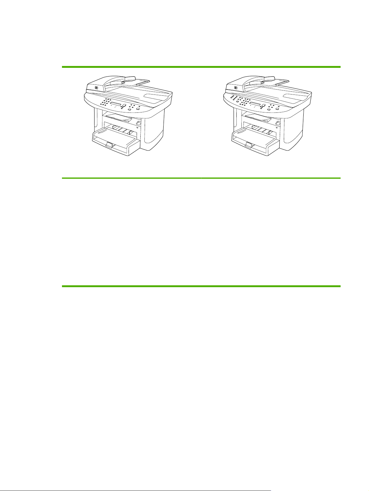
Product comparison
The product is available in the following configurations.
HP LaserJet M1522n MFP HP LaserJet M1522nf MFP
Prints letter-size pages at speeds up to 24 pages per
●
minute (ppm) and A4-size pages at speeds up to 23 ppm.
PCL 5 and PCL 6 printer drivers and HP postscript level 3
●
emulation.
Priority input tray holds up to 10 sheets of print media.
●
Tray 1 holds up to 250 sheets of print media or 10
●
envelopes.
Hi-Speed USB 2.0 port and 10/100 Base-T network port.
●
64-MB random-access memory (RAM).
●
Flatbed scanner and 50-page automatic document
●
feeder (ADF).
HP LaserJet M1522n MFP, plus:
V.34 fax modem and 4-megabyte (MB) flash fax-storage
●
memory.
Two RJ-11 fax phone line ports
●
ENWW Product comparison 3
Page 22

Product features
Performance
Print quality
Fax (fax models only)
Copy
Scan
Networking
Printer driver features
Prints up to 24 ppm (letter) or 23 ppm (A4).
●
600 x 2 dots per inch (dpi) with Resolution Enhancement Technology (RET).
●
Adjustable settings to optimize print quality.
●
The HP UltraPrecise print cartridge has a finer toner formulation that provides sharper text
●
and graphics.
Full-functionality fax capabilities with a V.34 fax; includes a phone book, fax/tel, and
●
delayed-fax features.
Includes ADF that allows faster, more efficient copy jobs with multiple-page documents.
●
The product provides 1,200 pixels per inch (ppi), 24-bit full-color scanning from letter/A4-
●
size scanner glass.
The product provides 300 ppi, 24-bit full-color scanning from the automatic document
●
feeder (ADF).
Includes an ADF that allows faster, more efficient scan jobs with multiple-page documents.
●
TCP/IP
●
IPv4
◦
IPv6
◦
Fast printing performance, built-in Intellifont and TrueType scaling technologies, and
●
advanced imaging capabilities are benefits of the PCL 6 printer language.
Interface connections
Economical printing
Supplies
Accessibility
Hi-Speed USB 2.0 port.
●
10/100 Base-T ethernet network port (RJ-45).
●
RJ-11 fax/phone cable ports (fax models only).
●
N-up printing (printing more than one page on a sheet).
●
EconoMode setting.
●
A supplies status page that displays the amount of life remaining in the print cartridge.
●
The product ships with a 1,000-page (average yield) starter cartridge. The average yield
●
for replacement cartridges is 2,000 pages.
Authentication for HP print cartridges.
●
Enabled supplies-ordering capability.
●
Online user guide that is compatible with text screen-readers.
●
Print cartridges can be installed and removed by using one hand.
●
All doors and covers can be opened by using one hand.
●
4 Chapter 1 Product information ENWW
Page 23
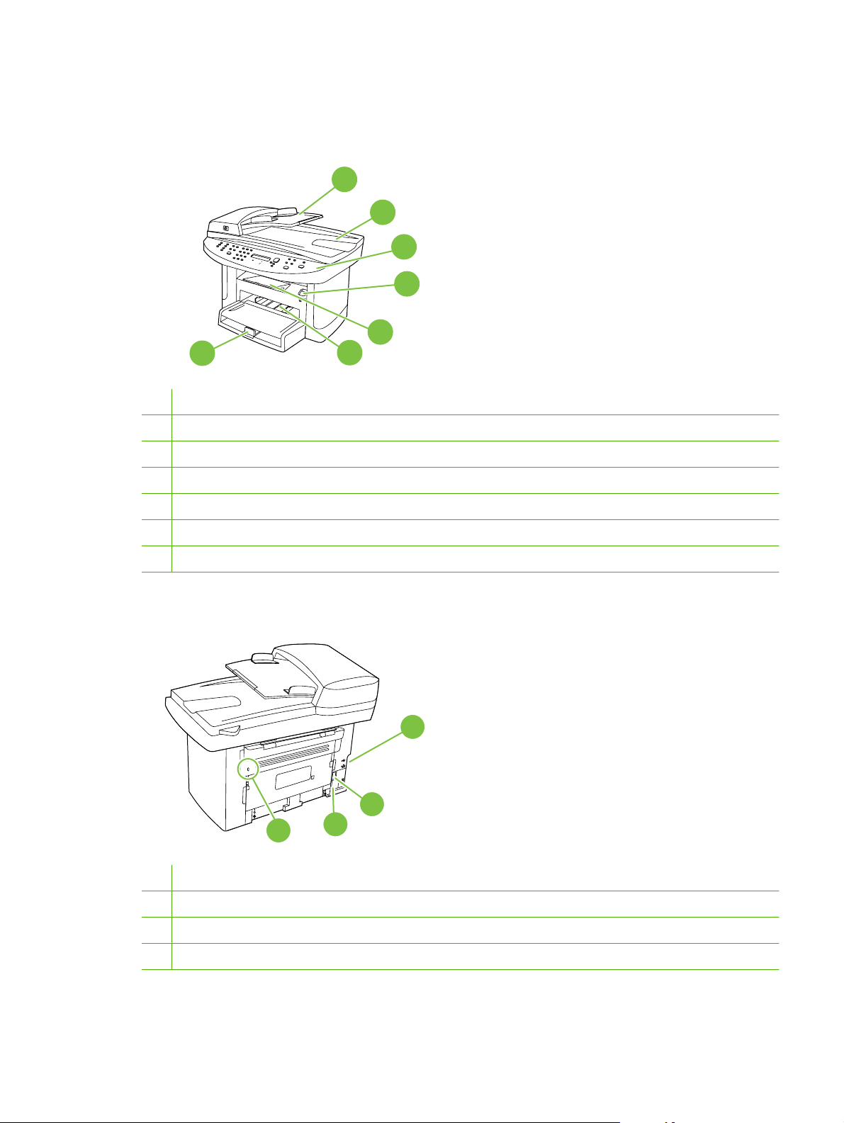
Product walkaround
Front view
7
1 Automatic document feeder (ADF) input tray
2 Automatic document feeder (ADF) output bin
3 Control panel
4 Print-cartridge door latch
5 Output bin
1
2
3
4
5
6
6 Priority input tray
7 Tray 1
Back view
8 Interface ports
9 Power switch
10 Power connector
11
10
9
8
7
11 Kensington lock
ENWW Product walkaround 5
Page 24
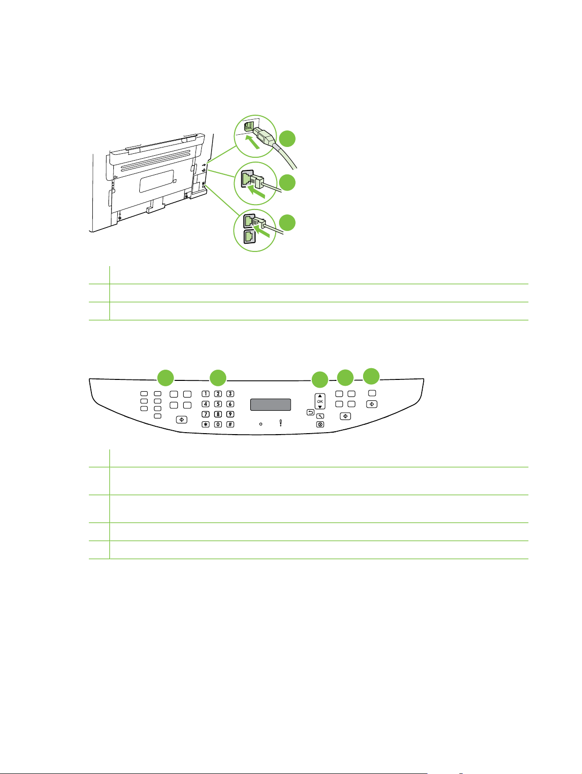
Interface ports
All models have a 10/100 Base-T (RJ-45) network port and a Hi-Speed USB 2.0 port. Fax models have
fax ports as well.
1 Hi-Speed USB 2.0 port
2 Network port
3 Fax ports (fax models only)
1
2
3
Control-panel
1 Fax controls (fax models only). Use the fax controls to change commonly used fax settings.
2 Alphanumeric buttons. Use the alphanumeric buttons to type data into the product control-panel display and dial
telephone numbers for faxing.
3 Setup and cancel controls. Use these controls to select menu options, determine the product status, and cancel the
current job.
4 Copy controls. Use these controls to change commonly used copy settings and to start copying.
5 Scan controls. Use these controls to scan to e-mail or to a folder.
1
2
3
4
5
6 Chapter 1 Product information ENWW
Page 25
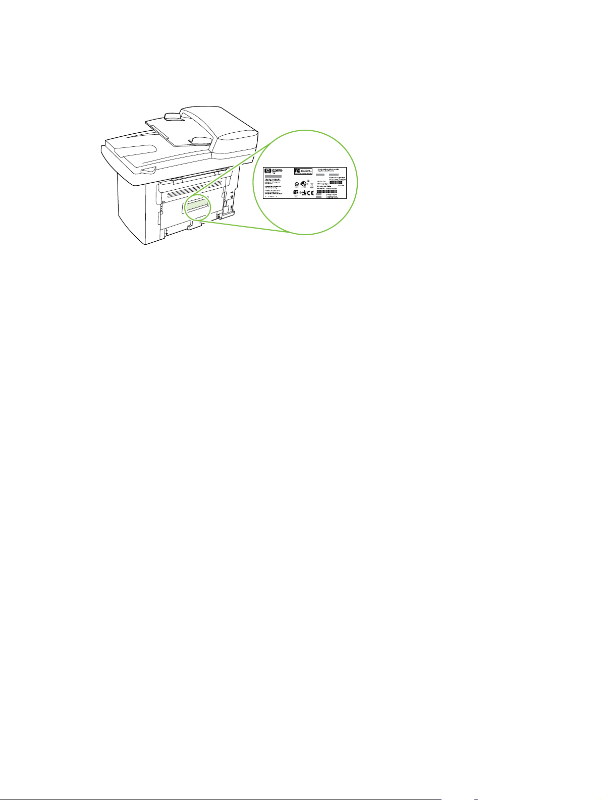
Serial number and model number location
The serial number and product model number label is on the back of the product.
ENWW Product walkaround 7
Page 26

Software description
Supported operating systems
The product supports the following operating systems:
Full software installation
Windows XP (32-bit and 64-bit)
●
Windows Vista (32-bit and 64-bit)
●
Mac OS X v10.3, v10.4, and later
●
NOTE: For Mac OS X v10.4 and later, PPC and Intel Core Processor Macs are supported.
Supported printer drivers
Operating system PCL 5 PCL 6 HP postscript level 3
Windows
Mac OS X v10.3, v10.4, and later
2
Linux
1
Driver can be installed by using the Microsoft Add Printer wizard, too.
2
For Linux, download the HP postscript level 3 emulation driver from www.hp.com/go/linuxprinting.
Print and scan driver
Windows 2000
●
Windows 2003 Server (32-bit)
●
1 1
Printer driver only
Linux (Web only)
●
UNIX model scripts (Web only)
●
emulation
The printer drivers include online Help that has instructions for common printing tasks and also describes
the buttons, checkboxes, and drop-down lists that are in the printer driver.
Software included with the product
There are several options for completing a recommended install. Easy Install will complete the
installation with default settings. Advanced Install allows you to select custom settings and choose the
components that are installed.
Recommended installation for Windows
HP drivers
●
PCL 6 printer driver
◦
Scan driver
◦
HP MFP software
●
HP ToolboxFX
◦
HP LaserJet Scan program
◦
HP Send Fax program and driver
◦
8 Chapter 1 Product information ENWW
Page 27

HP Fax Setup Wizard
◦
Uninstall program
◦
HP Update program
●
HP Customer Participation Program
●
Shop for HP Supplies program
●
Other programs
●
Readiris OCR (not installed with other software; separate installation is required)
◦
Express installation (USB or network)
The following software is included with an Express installation:
PCL 6 printer driver
●
Scan driver
●
NOTE: Express installation supports faxing by using the control panel.
NOTE: PCL 5 and HP postscript level 3 emulation drivers can be installed using the Microsoft Add
Printer wizard.
Macintosh software
HP Product Setup Assistant
●
HP Device Configuration
●
HP Uninstaller
●
HP LaserJet software
●
HP Scan
◦
HP Director
◦
Fax program
◦
Scan to e-mail program
◦
HP Photosmart
◦
Software for Windows
When you install the software for Windows, you can directly connect the product to a computer by using
a USB cable, or you can connect the product to a network by using the internal print server. See the
getting started guide for installation instructions, and see the Readme file for the latest software
information.
HP ToolboxFX
Perform a typical installation in order to use HP ToolboxFX.
ENWW Software for Windows 9
Page 28

HP ToolboxFX provides links to product status information and help information, such as the user guide,
and tools for product problem-solving.
Embedded Web server (EWS)
The EWS is a Web-based interface that provides simple access to product status and configurations,
including network configurations and Smart Printing Supplies (SPS) functionality.
You can gain access to the EWS through the network connection to the product. Type the product IP
address in a Web browser to open the product EWS home page in the browser. From the home page,
you can use the tabs and left navigation menu to check the status of the product, configure the product,
or check the status of the supplies.
The following are supported browsers:
Internet Explorer 5.0 or later
●
Netscape Navigator 4.75 or later
●
Opera 6.05 or later
●
Safari 1.2 or later
●
Software for Macintosh
For Mac OS X v10.3, v10.4, and later, use Print Center to print.
NOTE: For Macintosh computers, HP ToolboxFX is not supported.
HP Director
HP Director is a software program for working with documents. When the document is loaded into the
ADF and the computer is connected directly to the product, HP Director appears on the computer screen
to initiate faxing, scanning, or changing settings on the product through Macintosh Configure Device.
Also included is the HP product Setup Assistant, which sets up the fax and print queues.
Macintosh Configure Device (Mac OS X v10.3, v10.4, and later)
Macintosh Configure Device is a Web-based program that provides access to information about the
product (or example, information about supplies status and product settings). Use Macintosh Configure
Device to monitor and manage the product from the computer.
NOTE: You must perform a complete software installation to use Macintosh Configure Device.
Check the product status and print information pages.
●
Check and change product settings.
●
Check default print settings.
●
Check and change fax settings, including IP configuration, Advanced, mDNS, SNMP, network
●
configuration, and fax reports.
You can view Macintosh Configure Device when the product is directly connected to a computer or when
it is connected to the network.
10 Chapter 1 Product information ENWW
Page 29

NOTE: You do not have to have Internet access to open and use Macintosh Configure Device.
View Macintosh Configure Device when the product is connected to the computer
1. Open HP Director by clicking the HP Director icon in the dock.
2. In HP Director, click Settings.
3. Select Configure Device to open the Macintosh Configure Device home page in a browser.
View Macintosh Configure Device when the product is connected to the network
1. Open one of the following browsers:
Internet Explorer 5.0 or later
●
Netscape Navigator 4.75 or later
●
Opera 6.05 or later
●
Safari 1.2 or later
●
2. Type the IP address of the product into the Web browser to open the Macintosh Configure Device
home page.
PDEs (Mac OS X v10.3, v10.4, and later)
PDEs are code plug-ins that provide access to product features, such as information about the number
of copies, two-sided printing, and quality settings. An installation program for the PDEs and other
software is provided on the product CD for Macintosh.
Uninstall software
Windows
Use the Add or Remove Programs method in Windows to remove the product software. This method
does not require you to have the software CD.
1. Click Start, point to Settings, and then click Control Panel.
NOTE: In Windows XP, click Start, and then click Control panel.
2. Double-click Add or Remove Programs.
3. Scroll through the list of software programs and click HP LaserJet M2727.
4. Click Remove.
Macintosh
To remove the software, drag the PPD files to the trash can.
ENWW Uninstall software 11
Page 30

Media specifications
Supported paper and print media sizes
This product supports a number of paper sizes, and it adapts to various media.
NOTE: To obtain best print results, select the appropriate paper size and type in the print driver before
printing.
Table 1-2 Supported paper and print media sizes
Size Dimensions Priority input tray Tray 1
Letter 216 x 279 mm (8.5 x 11 inches)
Legal 216 x 356 mm (8.5 x 14 inches)
A4 210 x 297 mm (8.27 x 11.69 inches)
Executive 184 x 267 mm (7.24 x 10.51 inches)
A3 297 x 420 mm (11.69 x 16.54 inches)
A5 148 x 210 mm (5.83 x 8.27 inches)
1
A6
105 x 148 mm (4.13 x 5.83 inches)
11 x 17 279 x 432 mm (11 x 17 inches)
B4 (JIS) 257 x 364 mm (10.12 x 14.33 inches)
B5 (JIS) 182 x 257 mm (7.17 x 10.12 inches)
8k 270 x 390 mm (10.63 x 15.35 inches)
16k 197 x 273 mm (7.75 x 10.75 inches)
16k 195 x 270 mm (7.7 x 10.6 inches)
16k 184 x 260 mm (7.25 x 10.25 inches)
8.5 x 13 216 x 330 mm (8.5 x 13 inches)
1
4 x 6
1
5 x 8
10 x 15 cm
Custom Minimum—76 x 127 mm (3 x 5 inches); Maximum—
1
These sizes are supported as custom sizes.
1
107 x 152 mm (4 x 6 inches)
127 x 203 mm (5 x 8 inches)
100 x 150 mm (3.9 x 5.9 inches)
216 x 356 mm (8.5 x 14 inches)
12 Chapter 1 Product information ENWW
Page 31

Table 1-3 Supported envelopes and postcards
Size Dimensions Priority input tray Tray 1
Envelope #10 105 x 241 mm (4.13 x 9.49 inches)
Envelope DL 110 x 220 mm (4.33 x 8.66 inches)
Envelope C5 162 x 229 mm (6.93 x 9.84 inches)
Envelope B5 176 x 250 mm (6.7 x 9.8 inches)
Envelope Monarch 98 x 191 mm (3.9 x 7.5 inches)
Postcard 100 x 148 mm (3.94 x 5.83 inches)
Double postcard 148 x 200 mm (5.83 x 7.87 inches)
Supported paper types and tray capacity
This product has the following tray priority for feeding print media:
1. Priority input tray
2. Tray 1
Minimum media dimensions are 76 x 127 mm (3 x 5 inches).
Maximum media dimensions are 216 x 356 mm (8.5 x 14 inches).
To obtain the best print results, change the paper size and paper type settings in the printer driver before
printing.
Type is Media specifications Priority input tray capacity Tray 1 capacity
Plain
Color
Preprinted
Prepunched
Recycled
Light
Envelopes
Labels Standard 1 sheet Not supported.
Bond
Rough
75 g/m2 (20 lb) to 104 g/m2 (27 lb)
60 g/m2 (16 lb) to 74 g/m2 (20 lb)
Less than 90 g/m2 (24 lb)
75 g/m2 (20 lb) to 104 g/m2 (27 lb)
75 g/m2 (20 lb) to 104 g/m2 (27 lb)
Up to 10 sheets Up to 250 sheets
Up to 10 sheets Up to 260 sheets
1 envelope Up to 10 envelopes.
1 sheet Up to 250 sheets
1 sheet Up to 200 sheets
1
Transparencies 4 mm (0.1 inches) Monochrome
Overhead
Mid weight
2
96 g/m
(25 lb) to 110 g/m2 (29 lb)
1 sheet Up to 200 sheets
Up to 10 sheets Up to 200 sheets
ENWW Media specifications 13
Page 32

Type is Media specifications Priority input tray capacity Tray 1 capacity
1
Heavy
111 g/m2 (29 lb) to 130 g/m
2
(33 lb)
Extra heavy
131 g/m2 (33 lb) to 175 g/m
2
(47 lb)
Letterhead
1
The maximum stack height for tray 1 is 25 mm (0.9 inches).
2
75 g/m
(20 lb) to 104 g/m2 (27 lb)
Up to 10 sheets Not supported.
Up to 10 sheets Not supported.
Up to 10 sheets Up to 250 sheets
14 Chapter 1 Product information ENWW
Page 33

2 Installation
Site preparations
●
What was in the box
●
Install input devices
●
Install supplies
●
ENWW 15
Page 34

Site preparations
Operating environment
Place the product on a sturdy, level surface in a well-ventilated area. Make sure that the air vents are
not blocked and that the product is installed away from direct sunlight, open flames, and ammonia fumes.
Figure 2-1 Operating environment
7
00 mm (27.
5 inc
hes)
595 m
m
(
23.5 in
31
(
m
0 m
79
c
he
s)
s)
e
h
c
in
0
.
Store or install the product in an area that meets the following requirements:
Temperature (printer; operating) 15
●
Temperature (printer; storage) -20
●
Humidity (printer; operating) 10 to 80% relative humidity (no condensation)
●
Humidity (printer; storage) 10% to 90% relative humidity (no condensation)
●
Temperature (toner cartridge; storage) -20
●
Humidity (toner cartridge; storage) 10% to 90% relative humidity (no condensation)
●
o
to 32.5oC (59o to 90.5oF)
o
to 60oC (-4o to 140oF)
o
to 40o C (-4 to 104o F)
16 Chapter 2 Installation ENWW
Page 35

Minimum system requirements
Windows® 2000
●
Windows XP
●
Windows Millennium Edition (Me)
●
Windows Server 2000
●
Windows 98
●
Mac OS X v10.3 and later
●
128 MB RAM for Windows operating systems
●
32 MB RAM for Macintosh operating systems
●
250 MB hard-disk space (full installation)
●
CD-ROM drive
●
USB port
●
ENWW Site preparations 17
Page 36

What was in the box
The following components are included in the box.
NOTE: The USB and network cables are not included.
3
2
4
1
Item Description
1 HP LaserJet M1522 MFP
5
7
p
f
m
X
X
X
X
M
t
e
J
r
e
s
a
L
P
H
e
d
i
u
G
d
e
t
r
a
t
S
g
n
i
t
t
e
G
6
8
9
10
2 Automatic document feeder (ADF) input tray
3 Print cartridge
4 Control-panel faceplate (if not already installed)
5 Priority input tray extension
6 Start guide and support flyer
7 CD-ROMs (software and online user guide)
8 Power cord
9 Fax cord
10 Tray 1
18 Chapter 2 Installation ENWW
Page 37

Install input devices
ADF input tray
1. Open the ADF cover.
2. Align the two tabs on the input tray with the grooves in the ADF.
3. Slide the tray into the grooves until the tray snaps into place.
4. Close the ADF cover.
ENWW Install input devices 19
Page 38

Priority input tray
The priority input tray is accessed from the front of the product. The product prints from the priority input
tray before attempting to print from tray 1.
Media guides ensure that the media is correctly fed into the product and that the print is not skewed
(crooked on the media). When loading media, adjust the media guides to match the width of the media
that you are using.
20 Chapter 2 Installation ENWW
Page 39

Tray 1
1. Push tray 1 into the product
2. Open the tray cover, and then adjust the media guides out.
3. Load the paper in the tray, snug the media guides against the stack, and then close the try cover.
ENWW Install input devices 21
Page 40

Install supplies
Install the print cartridge
1. Open the print-cartridge door.
2. Remove the new print cartridge from its packaging, and then rock the print cartridge back and forth.
3. Remove the orange cover from the print cartridge, and then pull the orange tab straight out to
remove the sealing tape.
22 Chapter 2 Installation ENWW
Page 41
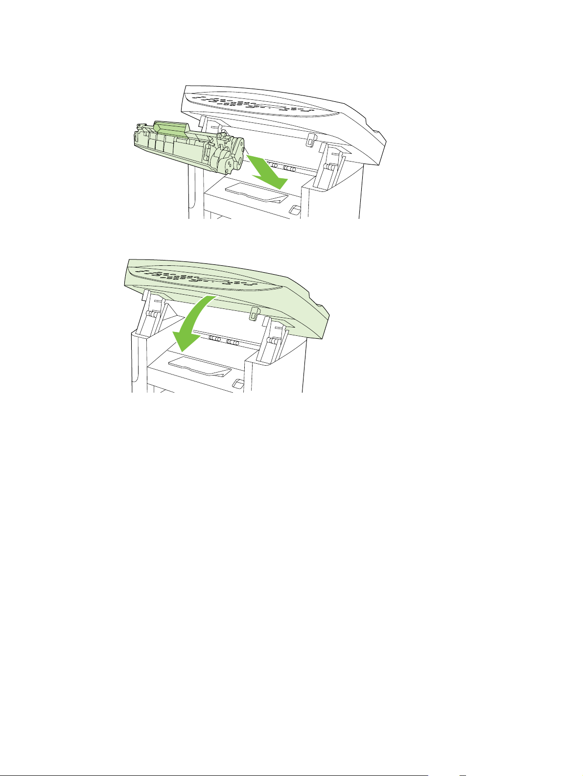
4. Insert the cartridge into the product until it is firmly in place.
5. Close the print-cartridge door.
ENWW Install supplies 23
Page 42

24 Chapter 2 Installation ENWW
Page 43

3 Maintenance
Manage supplies
●
Clean the product
●
Management tools
●
ENWW 25
Page 44

Manage supplies
This section describes replacing the print cartridge, the product pickup roller and separation pad, and
the ADF pickup roller and separation pad.
Inspect any parts that wear when servicing the product. Replace them as needed, based on failure or
wear rather than usage.
The following table lists approximate schedules for replacing consumables.
Life expectancies of supplies
Item Capacity
HP LaserJet M1522 MFP Series Recommended maximum of 3,000 pages per month
Print cartridge 2,000 pages1 (standard)
1
For information about the yield for the cartridges, see www.hp.com/go/pageyield. Actual yield depends on specific use.
Check and order supplies
You can check the supplies status by using the product control panel, printing a supplies status page,
or viewing HP ToolboxFX. Hewlett-Packard recommends that you place an order for a replacement print
cartridge when Low message for a print cartridge first appears. Use a new, authentic HP print cartridge
to obtain the following types of supplies information:
Amount of cartridge life remaining
●
Estimated number of pages remaining
●
Number of pages printed
●
Other supplies information
●
NOTE: If the product is connected to the network, you can set HP ToolboxFX to notify you by e-mail
when a print cartridge is low. If the product is directly connected to a computer, you can set
HP ToolboxFX to notify you when supplies are low.
Store supplies
Follow these guidelines for storing print cartridges:
Do not remove the print cartridge from its package until you are ready to use it.
●
CAUTION: To prevent damage, do not expose the print cartridge to light for more than a few
minutes.
See
●
Store the supply in a horizontal position.
●
Store the supply in a dark, dry location away from heat and magnetic sources.
●
Environmental specifications on page 245 for operating and storage temperature ranges.
26 Chapter 3 Maintenance ENWW
Page 45

Replace supplies
Print cartridge
1. Open the print-cartridge door.
2. Grasp the handle on the print cartridge, and then pull the cartridge straight out to remove it. See
the recycling information inside the print cartridge box.
3. Remove the new print cartridge from its packaging, and then rock the print cartridge back and forth.
ENWW Manage supplies 27
Page 46

4. Remove the orange cover from the print cartridge, and then pull the orange tab straight out to
remove the sealing tape.
5. Insert the cartridge into the product until it is firmly in place.
6. Close the print-cartridge door.
CAUTION: If toner gets on any clothing, wipe it off with a dry cloth and wash the clothing in cold water.
Hot water sets toner into the fabric.
HP policy on non-HP supplies
Hewlett-Packard Company cannot recommend the use of non-HP supplies, either new or
remanufactured. Because they are not HP products, HP cannot influence their design or control their
quality. Service or repairs required as a result of using a non-HP supply will not be covered under the
warranty.
28 Chapter 3 Maintenance ENWW
Page 47

HP fraud hotline
Call the HP fraud hotline if the product or HP ToolboxFX indicates that the print cartridge is not an
HP print cartridge and you think that it is genuine. HP will help determine if the product is genuine and
take steps to resolve the problem.
The print cartridge might not be a genuine HP one if you notice the following issues:
You are experiencing a large number of problems with the print cartridge.
●
The print cartridge does not look like it usually does (for example, the pull tab or the box is different).
●
In the United States, call toll-free: 1-877-219-3183.
Outside the United States, you can call collect. Dial the operator and ask to place a collect call to this
telephone number: 1-770-263-4745. If you do not speak English, a representative at the HP fraud hotline
who speaks your language will assist you. Or, if someone who speaks your language is not available,
a language line interpreter will connect approximately one minute after the beginning of the call. The
language line interpreter is a service that will translate between you and the representative for the HP
fraud hotline.
ENWW Manage supplies 29
Page 48

Clean the product
Clean the exterior
Use a soft, damp, lint-free cloth to wipe dust, smudges, and stains off of the exterior of the product.
Clean the flatbed scanner glass
Dirty glass, from fingerprints, smudges, hair, and so on, slows down performance and affects the
accuracy of special features such as fit-to-page and copy.
NOTE: If streaks or other defects appear only on copies produced from the ADF, clean the ADF
scanner glass (step 3). It is not necessary to clean the flatbed scanner glass.
1. Turn off the product, unplug the power cord from the electrical outlet, and raise the scanner cover.
2. Clean the glass by using a soft cloth or sponge that has been moistened with nonabrasive glass
cleaner.
CAUTION: Do not use abrasives, acetone, benzene, ammonia, ethyl alcohol, or carbon
tetrachloride on any part of the product; these can damage the product. Do not place liquids directly
on the glass. They might seep under it and damage the product.
3. Clean the ADF scanner glass by using a soft cloth or sponge that has been moistened with
nonabrasive glass cleaner.
30 Chapter 3 Maintenance ENWW
Page 49

Clean the scanner-cover backing
1. Turn off the product, unplug the power cord from the electrical outlet, and raise the scanner cover.
2. Clean the white scanner-cover backing by using a soft cloth or sponge that has been moistened
with mild soap and warm water. Also, clean the ADF scanner glass (callout 1) next to the flatbed
scanner glass.
3. Wash the backing gently to loosen debris; do not scrub the backing.
4. Dry the backing by using a chamois or soft cloth.
CAUTION: Do not use paper-based wipes because they might scratch the backing.
5. If this does not clean the backing well enough, repeat the previous steps and use isopropyl alcohol
to dampen the cloth or sponge, and then wipe the backing thoroughly with a damp cloth to remove
any residual alcohol.
ENWW Clean the product 31
Page 50

Clean the ADF pickup-roller assembly
1. Perform the removal steps from ADF pickup roller assembly on page 85.
2. Wipe the assembly with a soft cloth.
3. Return the assembly to the same place in the ADF. The largest roller goes in back, and the gear
side is away from you.
4. Lower the green lever until the flat green part fits between the rollers. Press down on the green
lever until you hear a snap.
32 Chapter 3 Maintenance ENWW
Page 51

5. To check for correct installation, lift the green lever until it remains open. The pickup-roller assembly
should be secured to the lever and should not fall out.
6. Make sure that both sides of the assembly are secured with the green hooks.
7. Lower the green lever and the roller assembly and close the ADF cover.
8. Plug in the product, and then turn it on.
ENWW Clean the product 33
Page 52

Clean the paper path
During the printing process, paper, toner, and dust particles can accumulate inside the product. Over
time, this buildup can cause print-quality problems such as toner specks or smearing. This product has
a cleaning mode that can correct and prevent these types of problems.
Specks Smearing
Clean the paper path from HP ToolboxFX
Use HP ToolboxFX to clean the paper path. This is the recommended cleaning method. If you do not
have access to HP ToolboxFX, use the method in
on page 34.
Clean the paper path from the product control panel
1. Make sure that the product is turned on and in the Ready state, and that media is loaded in tray 1
or tray 2.
2. Open HP ToolboxFX, click the product, and then click the System Settings tab.
3. Click the Service tab, and then click Start.
A page feeds through the product slowly. Discard the page when the process is completed.
Clean the paper path from the product control panel
If you do not have access to HP ToolboxFX, you can print and use a cleaning page from the product
control panel.
1.
Press Setup
2. Use the arrow buttons to select the Service menu, and then press OK.
3. Use the arrow buttons to select Cleaning mode, and then press OK.
4. Load plain letter or A4 paper when you are prompted.
5. Press OK again to confirm and begin the cleaning process.
A page feeds through the product slowly. Discard the page when the process is completed.
.
Calibrate the scanner
During the printing process, paper, toner, and dust particles can accumulate inside the product. Over
time, this buildup can cause print-quality problems such as toner specks or smearing. This product has
a cleaning mode that can correct and prevent these types of problems.
34 Chapter 3 Maintenance ENWW
Page 53

Calibrate the scanner from HP ToolboxFX
1. Open HP ToolboxFX.
2. Click the product, and then click the Device Settings folder.
3. Click the Print Quality page, and then select Calibrate now.
4. Click Apply to start the calibration process.
Calibrate the scanner from the product control panel
1.
At the control panel, press Setup
2. Open the Secondary Service menu by pressing and holding both the down arrow button and the
Cancel button.
3.
Press Setup
4. Use the arrow buttons to select Calibrate, and then press OK.
5. Use the arrow buttons to select the calibration mode, and then press OK.
The product scanner calibrates slowly. When the calibration process completes, the product prints
a calibration report.
again.
.
ENWW Clean the product 35
Page 54

Management tools
Information pages
Information pages reside within the product memory. These pages help diagnose and solve problems
with the product.
NOTE: If the product language was not correctly set during installation, you can set the language
manually so the information pages print in one of the supported languages. Change the language by
using the System setup menu on the control panel or the embedded Web server (EWS).
Page description How to print the page
Configuration page
Shows the current settings and product properties.
Supplies status page
Shows the remaining life of the HP print cartridge, the
estimated pages remaining, the number of pages printed, and
other supplies information.
PCL, PCL 6, or PS font list
Shows which fonts are currently installed in the device.
Demo page
Contains examples of text and graphics.
1.
On the product control panel, press Setup
2. Use the arrow buttons to select Reports, and then press
OK.
3. Use the arrow buttons to select Config report, and then
press OK.
A second page also prints. On that page, the Fax Settings
section provides details about the product fax settings.
1.
On the product control panel, press Setup
2. Use the arrow buttons to select Reports, and then press
OK.
3. Use the arrow buttons to select Supplies Status, and
then press OK.
1.
On the product control panel, press Setup
2. Use the arrow buttons to select Reports, and then press
OK.
3. Use the arrow buttons to select PCL font list, PS font
list, or PCL6 font list, and then press OK.
1.
On the product control panel, press Setup
2. Use the arrow buttons to select Reports, and then press
OK.
.
.
.
.
3. Use the arrow buttons to select Demo page, and then
press OK.
Event log You can print the event log from HP ToolboxFX, the embedded
Usage page
Shows a page count for each size of paper printed, the number
of one-sided (simplexed) or two-sided (duplexed) pages, and
the average percentage of coverage.
Web server, or HP Web Jetadmin.
1.
On the product control panel, press Setup
2. Use the arrow buttons to select Reports, and then press
OK.
3. Use the arrow buttons to select Usage page, and then
press OK.
.
36 Chapter 3 Maintenance ENWW
Page 55

Page description How to print the page
Menu map
Shows the control-panel menus and available settings.
Network report
Shows the product network settings.
Fax reports 1.
1.
On the product control panel, press Setup
2. Use the arrow buttons to select Reports, and then press
OK.
3. Use the arrow buttons to select Menu structure, and then
press OK.
1.
On the product control panel, press Setup
2. Use the arrow buttons to select Reports, and then press
OK.
3. Use the arrow buttons button to select Network report,
and then press OK.
On the product control panel, press Setup
2. Use the arrow buttons to select Reports, and then press
OK.
3. Use the arrow buttons button to select Fax reports, and
then press OK.
4. Use the arrow buttons button to select the report that you
want to print, and then press OK.
.
.
.
HP ToolboxFX
HP ToolboxFX is a program that you can use to complete the following tasks:
Check the product status.
●
Configure the product settings.
●
View troubleshooting information.
●
View online documentation.
●
You can view HP ToolboxFX when the product is directly connected to a computer or when it is
connected to the network. You must perform the recommended full software installation to use
HP ToolboxFX.
View HP ToolboxFX
Open HP ToolboxFX in one of these ways:
In the Windows system tray or on your desktop, double-click the HP ToolboxFX icon.
●
On the Windows Start menu, click Programs (or All Programs in Windows XP), click HP, click
●
HP LaserJet M1522, and then click HP ToolboxFX.
ENWW Management tools 37
Page 56

Status
Event log
The HP ToolboxFX Status tab contains links to the following main pages:
Device Status. View product status information. This page indicates product conditions such as
●
a jam or an empty tray. After you correct a problem with the product, click Refresh status to update
the product status.
Supplies Status. View detailed supplies information such as the estimated percent of life
●
remaining in the print cartridge and the number of pages that have been printed with the current
print cartridge. This page also has links to order supplies and to find recycling information.
Device Configuration. View a detailed description of the current product configuration, including
●
the amount of memory installed and whether optional trays are installed.
Network Summary. View a detailed description of the current network configuration, including the
●
IP address and network status.
Print Info Pages. Print the configuration page and various other information pages that are
●
available for the product, such as the supplies status page and the demo page.
Event Log. View a history of product errors. The most recent error is at the top of the list.
●
The event log is a four-column table where the product events are logged for your reference. The log
contains codes that correspond to the error messages that appear on the product control-panel display.
The number in the Page Count column specifies the total number of pages that the product had printed
when the error occurred. The event log also contains a brief description of the error. For more information
about error messages, see
Control-panel messages on page 140.
Alerts
The HP ToolboxFX Alerts tab contains links to the following main pages:
Set up Status Alerts . Set up the product to send you pop-up alerts for certain events, such as
●
low toner levels.
Set up E-mail Alerts. Set up the product to send you e-mail alert messages for certain events,
●
such as low toner levels.
Set up status alerts
Use HP ToolboxFX to set up the product so that it issues pop-up alerts to your computer when certain
events occur. Events that trigger alerts include jams, low levels of toner in HP print cartridges, non-HP
print cartridge in use, empty input trays, and specific error messages.
Select the pop-up format, the tray icon format, or both for the alerts. The pop-up alerts only appear when
the product is printing from the computer on which you set up the alerts.
NOTE: You must click Apply before the changes take effect.
Set up e-mail alerts
Use HP ToolboxFX to configure up to two e-mail addresses to receive alerts when certain events occur.
You can specify different events, such as a low cartridge or a paper jam, for each e-mail address. Enter
the information for the e-mail server that will send out the e-mail alert messages for the product.
38 Chapter 3 Maintenance ENWW
Page 57

Fax
Fax tasks
NOTE: You must click Apply before the changes take effect.
Use the HP ToolboxFX Fax tab to perform fax tasks from your computer. The Fax tab contains links to
the following main pages:
Fax Tasks. Set the fax receive mode.
●
Fax Phone Book. Add, edit, or delete entries in the product phone book.
●
Fax Send Log. View all of the recent faxes that have been sent from the product.
●
Fax Receive Log. View all of the recent faxes that have been received by the product.
●
Block Faxes. Add, delete, or view fax numbers that are blocked.
●
Fax Data Properties. Manage the space used to store faxes on your computer. These settings
●
apply only if you have chosen to send or receive faxes remotely from your computer.
The following three options are available when receiving a fax:
Print the fax. You can also select an option to have a message appear on your computer to notifying
●
you when the fax was printed.
Receive the fax on your computer. You can also select an option to have a message appear on
●
your computer to notifying you when the fax arrives. If the fax machine is connected to multiple
computers, only one computer can be designated to receive faxes.
Forward the fax to another fax machine.
●
For more information about fax tasks, see the user guide.
NOTE: You must click Apply before the changes take effect.
Fax phone book
Use the HP ToolboxFX fax phone book to add and remove individuals or groups on your speed-dial list,
import phone books from a variety of sources, and update and maintain the contact list.
To add an individual contact to the speed-dial list, select the row of the speed dial number that you
●
want to specify. Type the contact name in the Contact name window. Type the fax number in the
Fax number window. Click Add.
To add a group of contacts to the speed-dial list, select the row of the speed-dial number that you
●
want to specify. Click Add Group. Double-click a contact name from the list on the left to move it
to the group list on the right, or select a name on the left and then click the appropriate arrow to
move it to the group list on the right. You can also use those two methods to move names from
right to left. When you have created a group, type a name in the Group name window, and then
click OK.
To edit an existing individual speed-dial entry, click anywhere on the row containing the contact
●
name to select it, and then click Update. Type changes in the appropriate windows, and then click
OK.
ENWW Management tools 39
Page 58

To edit an existing group-speed-dial entry, click anywhere on the row containing the group name
●
to select it, and then click Update. Make any required changes, and then click OK.
To delete an entry from the speed-dial list, select the item, and then click Delete.
●
To move speed dial entries, select the entry and then click Move, or select Move and then specify
●
the entry in the dialog box. Either select Next empty row or specify the number of the row where
you want to move the entry.
NOTE: If you specify a row that is occupied, the new entry will overwrite the existing entry.
To import contacts from a phone book that exists in Lotus Notes, Outlook, or Outlook Express, click
●
Import/Export Phone Book. Select the Import option, and then click Next. Select the appropriate
software program, navigate to the appropriate file, and then click Finish. To export contacts from
a phone book, click Import/Export Phone Book. Select the Export option, and then click Next.
Enter the file name or browse to the file to which you want to export contacts, and then click
Finish. You can also select individual entries from the phone book instead of importing the entire
phone book.
To delete all entries, click Delete All, and then click Yes.
●
In addition to numerical digits, the following are valid characters for fax numbers:
(
●
)
●
+
●
-
●
*
●
#
●
R
●
W
●
.
●
,
●
<space>
●
NOTE: You must click Apply before the changes take effect.
see the user guide.
40 Chapter 3 Maintenance ENWW
Page 59

Fax send log
The HP ToolboxFX fax send log lists all recently sent faxes and information about them, including the
date and time sent, job number, fax number, page count, and the results.
Click any column heading in the fax send log to re-sort the information in that column in ascending or
descending order.
The Results column provides the fax status. If the fax attempt was unsuccessful, this column provides
a description of why the fax was not sent.
See the user guide.
Fax receive log
The HP ToolboxFX fax receive log provides a list of all recently received faxes and information about
them including the date and time received, job number, fax number, page count, results, and an
abbreviated fax image.
The fax receive log can be used to block future faxes. Check the Block Fax box next to a received fax
listed on the log.
When a computer that is connected to the product receives a fax, the fax contains a View link. Clicking
this link opens a new page that provides information about the fax.
Click on any column heading in the fax receive log to re-sort the information in that column in ascending
or descending order.
The Results column provides the fax status. If the fax attempt was unsuccessful, this column provides
a description of why the fax was not received.
NOTE: You must click Apply before the changes take effect.
See the user guide.
Block Faxes
Block Faxes provides a list of all numbers that are blocked. Add, modify, or delete blocked fax numbers
on this tab.
Help
The HP ToolboxFX Documentation tab contains links to the following main pages:
●
●
●
Troubleshooting
Animated demonstrations
User Guide. View information about the product usage, warranty, specifications, and support. The
user guide is available in both HTML and PDF format.
ENWW Management tools 41
Page 60

System Settings
The HP ToolboxFX System Settings tab contains links to the following main pages:
Device Information. View information about the product, such as the product description and a
●
contact person.
Paper Handling. Change the product paper-handling settings, such as default paper size and
●
default paper type.
Print Quality. Change the product print-quality settings.
●
Paper Types. Change the product mode settings for each media type, such as letterhead,
●
prepunched, or glossy paper.
System Setup. Change the product system settings, such as product language and jam recovery.
●
Service. Gain access to various procedures required to maintain the product.
●
Device Polling. Change the product polling settings, which determine how often HP ToolboxFX
●
collects data from the product.
Save/Restore Settings. Save the current settings for the product to a file on the computer. Use
●
this file to load the same settings onto another product or to restore these settings to this product
at a later time.
Password. Set, change, or clear the product security password.
●
NOTE: A single password can be set from the control panel, HP ToolboxFX, or the embedded
Web server (EWS).
Device information
The HP ToolboxFX Device information page stores data about the product for future reference. The
information that you type in these fields appears on the Configuration page. You can type any character
in each of these fields.
NOTE: You must click Apply before the changes take effect.
42 Chapter 3 Maintenance ENWW
Page 61

Paper handling
Use the HP ToolboxFX paper-handling options to configure the default settings. These are the same
options that are available on the product control-panel.
Three options are available for handling print jobs when the product is out of media:
●
●
●
The Paper out time field specifies how long the product waits before acting on the selections. You can
specify from 0 to 3600 seconds.
NOTE: You must click Apply before the changes take effect.
Print quality
Use the HP ToolboxFX print-quality options to improve the appearance of print jobs. These are the same
options that are available on the product control panel.
The four options provided for controlling print quality are resolution, REt (Resolution Enhancement
technology), print density, and EconoMode.
●
Select Wait for paper to be loaded.
Select Cancel from the Paper out action drop-down list to cancel the print job.
Select Override from the Paper out time drop-down list to send the print job to another paper tray.
Resolution. Select 600 resolution for average print jobs and Fast Res 1200 for higher-quality print
jobs.
●
●
●
NOTE: You must click Apply before the changes take effect.
Paper types
Use the HP ToolboxFX Paper types options to configure print modes that correspond to the various
media types. Select Restore Modes to reset all modes to the factory settings.
NOTE: You must click Apply before the changes take effect.
REt. You can turn on REt, which HP provides for improved print quality.
Print density. For increased print density, select a higher number. For decreased print density,
select a lower number.
EconoMode. Turn EconoMode on when you are printing average print jobs. EconoMode is a
feature that allows the product to use less toner per page. Selecting this option might extend the
life of the toner supply and might reduce cost per page. However, it will also reduce print quality.
The printed image is lighter, but it is adequate for printing drafts or proofs. HP does not recommend
full-time use of EconoMode. If EconoMode is used full-time, it is possible that the toner supply will
outlast the mechanical parts in the print cartridge. If print quality begins to degrade under these
circumstances, you will need to install a new print cartridge, even if there is toner supply remaining
in the cartridge.
ENWW Management tools 43
Page 62

System setup
Use the HP ToolboxFX system settings options to configure global settings for copy, fax, scan, and print,
such as jam recovery and auto-continue.
NOTE: You must click Apply before the changes take effect.
Service
During the printing process, paper, toner and dust particles can accumulate inside the product. Over
time, this buildup can cause print-quality problems such as toner specks or smearing. HP ToolboxFX
provides an easy method for cleaning the paper path. For more information, see
from HP ToolboxFX on page 34.
Device polling
You can turn off HP ToolboxFX device polling to reduce network traffic, but doing so also disables some
HP ToolboxFX features: pop-up alerts, fax log updates, the ability to receive faxes to this computer, and
scanning using the Scan To button.
NOTE: You must click Apply before the changes take effect.
Print Settings
The HP ToolboxFX Print Settings tab contains links to the following main pages:
Clean the paper path
Printing
Printing. Change the default product print settings, such as number of copies and paper
●
orientation.
PCL5e. View and change the PCL5 settings.
●
PostScript. View and change the PS settings.
●
Use the HP ToolboxFX printing settings options to configure the settings for all print functions. These
are the same options that are available on the product control panel.
NOTE: You must click Apply before the changes take effect.
44 Chapter 3 Maintenance ENWW
Page 63

PCL 5e
Use the PCL 5 options to configure the settings when you are using the PCL 5 print personality. These
are the same options that are available on the PCL5 menu on the control panel.
NOTE: You must click Apply before the changes take effect.
PostScript
Use the PostScript option when you are using the HP postscript level 3 emulation print personality. When
the Print PostScript error option is turned on, the PostScript error page automatically prints when
HP postscript level 3 emulation errors occur.
NOTE: You must click Apply before the changes take effect.
Network Settings
The network administrator can use the HP ToolboxFX Network Settings tab to control the networkrelated settings for the product when it is connected to an IP-based network.
Embedded Web server
This product is equipped with an embedded Web server (EWS), which provides access to information
about product and network activities. A Web server provides an environment in which web programs
may run, much in the same way that an operating system, such as Windows, provides an environment
for programs to run on a computer. The output from these programs can then be displayed by a Web
browser, such as Microsoft Internet Explorer, Safari, or Netscape Navigator.
Features
An “embedded” Web server resides on a hardware device (such as an HP LaserJet product) or in
firmware, rather than as software that is loaded on a network server.
The advantage of an EWS is that it provides an interface to the product that anyone with a networkconnected product and computer can use. There is no special software to install or configure, but you
must have a supported Web browser on the computer. To gain access to the EWS, type the IP address
for the product in the address line of the browser. (To find the IP address, print a configuration page.
For more information about printing a configuration page, see
NOTE: For Macintosh operating systems, you can use the EWS over a USB connection after installing
the Macintosh software included with the product.
The EWS allows you to view product and network status and manage printing functions from a computer.
With the EWS, you can complete the following tasks:
View product status information
●
Determine the remaining life on all supplies and order new ones
●
View and change part of the product configuration
●
View and print some internal pages
●
Select the language in which to display the EWS pages
●
Information pages on page 36.)
View and change network configuration
●
Set, change, or clear the product security password.
●
ENWW Management tools 45
Page 64

NOTE: Changing network settings in the EWS might disable some of product software or features.
Use HP Web Jetadmin software
HP Web Jetadmin is a Web-based software solution for remotely installing, monitoring, and
troubleshooting network-connected peripherals. The intuitive browser interface simplifies cross-platform
management of a wide range of devices, including HP and non-HP devices. Management is proactive,
allowing network administrators the ability to resolve issues before users are affected. Download this
free, enhanced-management software at
To obtain plug-ins to HP Web Jetadmin, click plug-ins, and then click the download link that is next to
the name of the plug-in that you want. The HP Web Jetadmin software can automatically notify you
when new plug-ins are available. On the Product Update page, follow the directions to automatically
connect to the HP Web site.
If installed on a host server, HP Web Jetadmin is available to any client through a supported Web
browser, such as Microsoft Internet Explorer 6.0 for Windows or Netscape Navigator 7.1 for Linux.
Browse to the HP Web Jetadmin host.
NOTE: Browsers must be Java-enabled. Browsing from an Apple PC is not supported.
www.hp.com/go/webjetadmin_software.
46 Chapter 3 Maintenance ENWW
Page 65

4 Operational theory
Basic operation
●
Scanner and ADF functions and operation
●
Internal components (base unit)
●
Engine control system
●
Laser/scanner system
●
Pickup/feed/delivery system
●
Image-formation system
●
Fax functions and operation (fax models only)
●
ENWW 47
Page 66

Basic operation
This chapter presents an overview of the relationships between major components in the product, and
includes a detailed discussion of the image-formation system. The following systems are discussed:
Engine control system
●
Laser/scanner system
●
Pickup/feed/delivery system
●
Image-formation system
●
Figure 4-1 System block diagram
Sequence of operation for the base unit
Operational sequences are controlled by the microprocessor and the DC controller.
Table 4-1 Sequence of operation
Name Timing Purpose
WAIT From power-on until the end of the main-motor initial
drive
STBY (standby) From the end of the WAIT or LSTR period until either
a print command is sent from the formatter or the
power is turned off
INTR (initial
rotation)
From the time of the print command until the pickup
solenoid is turned on
48 Chapter 4 Operational theory ENWW
Detects the presence of a print cartridge; clears
potential from the drum surface and cleans the
transfer roller
Table 4-2 Power-on sequence on page 49 for
See
a complete description of the WAIT (power-on)
period.
Prepares the product to receive print commands
Prepares the photosensitive drum for printing
Page 67

Table 4-1 Sequence of operation (continued)
Name Timing Purpose
PRINT From the end of the INTR period until the primary
high-voltage is turned off
LSTR (last
rotation)
From the end of the PRINT period (when high-voltage
is turned off) until the main motor stops rotating
Table 4-2 Power-on sequence
Step Action
1 Power-on
2 CPU initialization
3 Start video interface communication
4 Check sensors for residual media
5 Main motor initial drive
6
7 Laser/scanner motor initial drive
8 High-voltage control
Fuser heater initial drive. The fuser heater reaches a surface temperature of 100o C.
Forms the image on the photosensitive drum and
transfers the toner image to the media
Delivers the last page of a print job
After LSTR, the product either returns to STBY or, if
another print command was sent from the formatter,
enters INTR.
Detect presence of a print cartridge
Clean the transfer roller after the primary charging AC bias is turned on
9 Failure/abnormality check: detect laser/scanner failure, fuser failure, and open covers
10 Communication with the memory tag
ENWW Basic operation 49
Page 68

Scanner and ADF functions and operation
The following sections describe how the document scanner and the automatic document feeder (ADF)
function.
Scanner functions
The scanner uses a light source, a color-separation method, and a charge-coupled device array (CCD)
to collect optical information about the document and transform that into an image file. The scanner
consists of these elements:
A lamp (LED)
●
Five mirrors and a lens
●
A CCD
●
Figure 4-2 Optical system
Scanner Glass
LED Lamp
CCD
Lens
The scanner lamp illuminates a small strip of the document (called the raster line). The mirrors direct
the light through the lens to the CCD. The CCD senses and records the light, creating an analog
representation of the raster line. If the ADF is being used, the document then advances in the ADF to
the next raster line. If the flatbed is being used, the scanner module advances to the next raster line.
This advancing and collection process continues to the end of the sheet.
The image data is collected in the motor controller board, where it is processed and sent to the formatter.
The formatter then handles the image data, outputting it as a copy, sending it through the fax card as a
fax, or directing it to the computer as scanner output.
The resolution of the image data collected depends on the task being performed. Each pixel has 8 bits
for each of the three colors (256 gray scale levels for each color), or a total of 24 bits per pixel (24-bit
color).
50 Chapter 4 Operational theory ENWW
Page 69

Scanner operation
At power-on and periodically at other times, the scanner assembly moves systematically to locate its
home position. It then calibrates to a white strip located under the glass at the right end of the scan tub.
If the product detects a document in the ADF when a copy or scan is initiated (from the software or the
control panel), the scan module moves to the left side of the scan tub and stops. The image is acquired
as the paper is fed through the ADF past the scanner module.
If no document is detected in the ADF, the scan module acquires the image from the flatbed glass while
slowly moving within the scan tub.
ADF operation
Standby (paper-loading) mode: In standby mode, the pickup roller is up and the stack-stop is down,
preventing the user from inserting the original document too far. When a document is inserted correctly,
the paper-present sensor detects its presence.
The standard operation of the ADF consists of the pick, feed, and lift steps.
Pick: When it receives a copy or scan command, the ADF motor engages the gear train to lower the
pickup-roller assembly and raise the stack-stop. The first roller, called the pre-pick roller, moves the top
few sheets forward into the ADF. The next roller is the pickup roller. This roller contacts the ADF
separation pad, which separates multiple pages into single sheets.
Feed: The single sheet continues through the path. Along the way, the form sensor, which is a set
distance from the ADF glass, detects the sheet. This alerts the scanner to start when the page reaches
the glass. The scanner acquires the image, one raster line at a time, until it detects the end of the page.
The page is then ejected. The pick and feed steps are repeated as long as paper is detected in the ADF
input tray.
Lift: When no more paper is detected in the ADF input tray and the form sensor detects the trailing edge
of the last page, the last sheet is ejected and the motor turns in a sequence that lifts the pick-roller
assembly to standby (paper-loading) mode again.
The ADF will not function when the ADF cover is open. The paper path is incomplete if the ADF cover
is lifted from the glass.
ENWW Scanner and ADF functions and operation 51
Page 70

ADF paper path and ADF sensors
The following diagram shows the ADF paper path.
Figure 4-3 ADF paper path
Pick roller
Paper present sensor
Separation pad
Cleanout
Form sensor
Prescan rollers
Stack stop
ADF door
open flag
Postscan
rollers
ADF glass
Pre-pick roller
Picks top sheet
INPUT TRAY
PAGE EJECTS FULLY
OUTPUT AREA
The paper-present sensor determines if paper is in the ADF. The form sensor detects the top and bottom
edges of the document. One other sensor detects an open ADF door.
52 Chapter 4 Operational theory ENWW
Page 71

ADF jam detection
The ADF has two sensors that detect paper. The paper-present sensor detects the presence of media
in the ADF input tray. The form sensor detects media moving through the ADF. If a jam is detected, the
ADF immediately stops the paper feeding and a jam message appears on the control-panel display.
A jam can be detected under any of the following conditions:
Document-feeder jam. When documents are detected in the ADF input tray, and a command to
●
copy, scan or fax is received, the scan module travels to the left side of the scan assembly and
stops beneath the ADF scanner glass. The ADF then attempts three times, or for about ten
seconds, to advance the paper to the form sensor. If the paper does not advance, the scan module
travels back to the home position on the right side of the scanner assembly. The message
Document feeder mispick. Reload. appears on the control-panel display.
Long-document jam. If the paper has advanced to trigger the form sensor, but the trailing edge
●
is not detected within the time allowed for a 381-mm (15-inch) document (the maximum allowable
page length for the ADF), the scanner returns to the home position on the right side of the scanner
assembly. The message Doc feeder jam. Clear, Reload. appears on the control-panel display.
Stall jam. When a page that is less than 381 mm (15 inches) long has advanced to the form sensor
●
but has not left it within the expected time, the paper has probably stalled or jammed. The scanner
returns to the home position on the right side of the scanner assembly. The message Doc feeder
jam. Clear, Reload. appears on the control-panel display.
Other. If the paper stops in the ADF and the scan module remains under the ADF scanner glass,
●
an internal firmware error has probably occurred. This is usually remedied by cycling the power.
ENWW Scanner and ADF functions and operation 53
Page 72

Internal components (base unit)
Figure 4-4 Cross-section of printer
1 2 3 4
5
6
1 Fuser unit
2 Pressure roller
3 Fuser sleeve
4 Delivery roller
5 Laser/scanner unit
6 Single-sheet-feed slot
7 Multi-purpose tray
8 Photosensitive drum
9 Pickup roller
10 Separation pad
11 Feed roller
12 Transfer roller
789101112
54 Chapter 4 Operational theory ENWW
Page 73

Engine control system
The engine control system coordinates all of the product functions, according to commands sent from
the formatter. It drives the laser/scanner system, the image-formation system, and the pickup/feed/
delivery system.
The engine control system contains the following components:
Formatter
●
High-voltage PCA
●
Figure 4-5 Engine control system
ENWW Engine control system 55
Page 74

Figure 4-6 Engine-control-system circuit diagram
ECU PCA
Main motor
Fuser
AC input
Fan
Transfer roller
Pressure roller
Print cartridge
Memory tag
Fuser control
circuit
Low-voltage power
supply circuit
Fan motor drive
circuit
IC502
Reset IC
High-voltage
power supply
circuit
Memory tag circuit
Solenoids
Sensors
IC201
CPU
Option
Laser/scanner
motor
Formatter
Laser driver
BD sensor
56 Chapter 4 Operational theory ENWW
Page 75

Laser/scanner system
The laser/scanner system receives video signals from the formatter, and converts the signals into latent
images on the photosensitive drum.
Figure 4-7 Laser/scanner system
ENWW Laser/scanner system 57
Page 76

Pickup/feed/delivery system
The pickup/feed/delivery system consists of several types of feed rollers and sensors. A motor and
solenoid are used to drive the rollers. Three media-detection sensors detect media as it passes through
the printer. If media does not reach or pass each sensor within a specified time period, the formatter
determines that a jam has occurred.
The following components are identified in
M1, main motor
●
SL1, pickup solenoid
●
PS751, top-of-page sensor
●
PS915, fuser-delivery sensor and duplex sensor
●
Figure 4-8 Pickup/feed/delivery system on page 58:
NOTE: This sensor has two sensor flags; one flag detects the media when it is delivered from
the fuser, and the other flag detects the media when it is reversed for duplexing.
PS702, media-width sensor
●
Figure 4-8 Pickup/feed/delivery system
PS701
Fuser
Feed roller
sleeve
Pressure roller
PS702
Photosensitive drum
Transfer roller
PS751
SL1
Separation pad
Pickup roller
M1
Single-sheet-feed tray
Multi-purpose tray
58 Chapter 4 Operational theory ENWW
Page 77

Image-formation system
Laser printing requires the interaction of several technologies, including electronics, optics, and
electrophotographics, to produce a printed page. Each process functions independently and must be
coordinated with the other product processes. Image formation consists of the following five processes:
Electrostatic latent-image formation
●
Developing
●
Transfer
●
Fusing
●
Drum cleaning
●
These five processes contain seven steps, which are shown in
on page 59 and described in the following sections.
Figure 4-9 Image-formation system
Step 1: Primary charging
DC and AC biases are applied to the primary charging roller, which transfers a uniform negative potential
to the photosensitive drum.
Figure 4-10 Primary charging
Figure 4-9 Image-formation system
ENWW Image-formation system 59
Page 78

Step 2: Laser beam exposure
The laser beam scans the photosensitive drum to neutralize negative charges on parts of the drum. An
electrostatic latent image is formed on the drum where negative charges were neutralized.
Step 3: Developing
The developing cylinder comes in contact with the photosensitive drum to deposit toner onto the
electrostatic latent image.
NOTE: The charges on the exposed area of the drum are shown as positive in Figure 4-11 Developing
on page 60. The charges are actually negative, but they are more positive than the charges on the
developing cylinder.
Figure 4-11 Developing
Toner acquires a negative charge through friction from the developing cylinder and the blade. When the
negatively charged toner comes in contact with the drum, the toner adheres to the electrostatic latent
image. The image on the drum becomes visible because of the toner.
Step 4: Transfer
The transfer charging roller, to which a DC positive bias is applied, imparts a positive charge on the print
media. When the print media comes in contact with the photosensitive drum, the toner is transferred to
the print media.
60 Chapter 4 Operational theory ENWW
Page 79

Figure 4-12 Transfer
Step 5: Separation
The elasticity of the print media causes its separation from the photosensitive drum. A static-charge
eliminator aids separation by weakening any electrostatic adhesion.
Figure 4-13 Separation
Step 6: Fusing
The DC negative bias applied to the fusing film strengthens the holding force of the toner on the print
media and prevents the toner from scattering.
Figure 4-14 Fusing
ENWW Image-formation system 61
Page 80

Step 7: Drum cleaning
The cleaning blade scrapes the residual toner off of the photosensitive drum and deposits it into the
waste-toner case.
Figure 4-15 Drum cleaning
62 Chapter 4 Operational theory ENWW
Page 81

Fax functions and operation (fax models only)
The following sections describe the product fax capabilities.
Computer and network security features
The product can send and receive fax data over telephone lines that conform to public switch telephone
network (PSTN) standards. The secure fax protocols make it impossible for computer viruses to be
transferred from the telephone line to a computer or network.
The following product features prevent virus transmission:
No direct connection exists between the fax line and any devices that are connected to the USB
●
or Ethernet ports.
The internal firmware cannot be modified through the fax connection.
●
All fax communications go through the fax subsystem, which does not use Internet data-exchange
●
protocols.
PSTN operation
The PSTN operates through a central office (CO) that generates a constant voltage on the TIP and
RING wires (48 V, usually). A device goes on-hook by connecting impedance (such as 600 ohms for
the U.S.) across the TIP and RING so that a line current can flow. The CO can detect this current and
can send impulses like dial tones. The product generates more signaling tones, such as dialing digits,
to tell the CO how to connect the call. The product can also detect tones, such as a busy tone from the
CO, that tell it how to behave.
When the call is finally connected, the CO behaves like a piece of wire connecting the sender and
receiver. This is the period during which all of the fax signaling and data transfer occurs. When a call is
completed, the circuit opens again and the line-current flow ceases, removing the CO connection from
both the sender and the receiver.
On most phone systems, the TIP and RING wires appear on pins 3 and 4 of the RJ-11 modular jack
(the one on the fax card). These two wires do not have to be polarized because all the equipment works
with either TIP or RING on pin 3 and the other wire on pin 4. This means that cables of either polarity
can interconnect and will still work.
These basic functions of PSTN operation are assumed in the design of the fax subsystem. The product
generates and detects the signaling tones, currents, and data signals that are required to transmit and
receive faxes on the PSTN.
Receive faxes when you hear fax tones
In general, incoming faxes to the product are automatically received. However, if other devices are
connected to the same phone line, the product might not be set to answer automatically.
If the product is connected to a phone line that receives both fax and phone calls, and you hear fax
tones when you answer the extension phone, receive the fax in one of two ways:
If you are near the product, press Start Fax on the control panel.
●
Press 1-2-3 in sequence on the extension phone keypad, listen for fax transmission sounds, and
●
then hang up.
ENWW Fax functions and operation (fax models only) 63
Page 82

NOTE: In order for the 1-2-3 sequence to work, the extension phone setting must be set to On in the
Fax setup menu.
Distinctive ring function
Distinctive ring is a service that a telephone company provides. The distinctive ring service allows three
phone numbers to be assigned to one phone line. Each phone number has a distinctive ring. The first
phone number has a single ring, the second phone number has a double ring, and the third phone
number has a triple ring.
NOTE: The product has not been tested with all of the distinctive-ring services that telephone
companies provide in all countries/regions. HP does not guarantee that the distinctive-ring function will
operate correctly in all countries/regions. Contact the local phone service provider for assistance.
Set up the distinctive ring function
1.
Press Setup
2. Use the arrow buttons to select Fax Recv. setup, and then press OK.
3. Use the arrow buttons to select Answer ring type, and then press OK.
4. Use the arrow buttons to select one of the following options:
NOTE: The control-panel display might show some of these options as abbreviations.
All rings (default setting)
●
Single
●
Double
●
Triple
●
DoubleTriple
●
Press OK to save the setting.
. Use the arrow buttons to select Fax setup, and then press OK.
Fax by using Voice over IP services
Voice over IP (VoIP) services provide normal telephone service, including long distance service through
a broadband Internet connection. These services use packets to break up the voice signal on a
telephone line and transmit it digitally to the receiver, where the packets are reassembled. The VoIP
services are often not compatible with fax machines. The VoIP provider must state the service supports
fax over IP services.
Because the installation process varies, the VoIP service provider will have to assist in installing the
product fax component.
Although a fax might work on a VoIP network, it can fail when the following events occur:
Internet traffic becomes heavy and packets are lost.
●
Latency (the time it takes for a packet to travel from its point of origin to its point of destination)
●
becomes excessive.
64 Chapter 4 Operational theory ENWW
Page 83

If you experience problems using the fax feature on a VoIP network, ensure that all of the product cables
and settings are correct. Configuring the Fax Speed setting to Medium(V.17) or Slow(V.29) can also
improve your ability to send a fax over a VoIP network.
If you continue to have problems faxing, contact your VoIP provider.
The fax subsystem
The formatter, fax card, firmware, and software all contribute to the fax functionality. The designs of the
formatter and fax card, along with parameters in the firmware, determine the majority of the regulatory
requirements for telephony on the product.
The fax subsystem is designed to support V.34 fax transmission, lower speeds (such as V.17 fax), and
older fax machines.
Fax card in the fax subsystem
Two versions of the fax card are used in the HP LaserJet M1522 MFP. One is used in the North
American, South American, and Asian countries/regions. The other is used primarily in European
countries/regions.
The fax card contains the modem chipset (DSP and CODEC) that controls the basic fax functions of
tone generation and detection, along with channel control for fax transmissions. The CODEC and its
associated circuitry act as the third-generation silicon DAA to achieve compliance world-wide regulatory
requirements.
European products must use the fax cord that is included in the product box. North American and Asian
products should be compatable with any phone cord, although users who experience fax errors should
try the included fax cord.
Safety isolation
The most important function of the fax card is the safety isolation between the high-voltage, transientprone environment of the telephone network (TNV [telephone network voltage]) and the low-voltage
analog and digital circuitry of the formatter (SELV [secondary extra-low voltage]). This safety isolation
provides both customer safety and product reliability in the telecom environment.
Any signals that cross the isolation barrier do so magnetically. The breakdown voltage rating of barriercritical components is greater than 5 kV.
Safety-protection circuitry
In addition to the safety barrier, the fax card protects against over-voltage and over-current events.
Telephone over-voltage events can be either differential mode or common mode. The event can be
transient in nature (a lightning-induced surge or ESD) or continuous (a power line crossed with a phone
line). The fax card protection circuitry provides margin against combinations of over-voltage and overcurrent events.
Common mode protection is provided by the selection of high-voltage-barrier critical components
(transformer and relay). The safety barrier of the fax card PCB traces and the clearance between the
fax card and surrounding components also contribute to common mode protection.
A voltage suppressor (a crowbar-type SIDACTOR) provides differential protection. This device becomes
low impedance at approximately 300 V differential, and crowbars to a low voltage. A series thermal
switch works in conjunction with the crowbar for continuous telephone line events, such as crossed
power lines.
ENWW Fax functions and operation (fax models only) 65
Page 84

All communications cross the isolation barrier magnetically. The breakdown voltage rating of barriercritical components is greater than 5 kV.
Data path
TIP and RING are the two-wire paths for all signals from the telephone network. All signaling and data
information comes across them, including fax tones and fax data.
The telephone network uses DC current to determine the hook state of the telephone, so line current
must be present during a call. The silicon DAA provides a DC holding circuit to keep the line current
constant during a fax call.
The silicon DAA converts the analog signal to a digital signal for DSP processing, and also converts the
digital signal to an analog signal for transmitting data through a telephone line.
The magnetically coupled signals that cross the isolation barrier go either through a transformer or a
relay.
The DSP in the fax card communicates with the ASIC in the formatter using the high-speed serial
interface.
Hook state
Another magnetically coupled signal is the control signal that disconnects the downstream telephone
devices (such as a phone or answering machine). A control signal originating on the DSP can change
the relay state, causing the auxiliary jack (downstream jack) to be disconnected from the telephone
circuit.
The product takes control of calls that it recognizes as fax calls. If the product does not directly pick up
the call, it monitors incoming calls for the fax tone or for the user to direct it to receive a fax. This idle
mode is also called eavesdropping. This mode is active when the product is on-hook but current exists
in the downstream phone line because another device is off-hook. During eavesdropping, the receive
circuit is enabled but has a different gain from the current that is generated during normal fax
transmissions.
The product does not take control of the line unless it detects a fax tone or the user causes it to connect
manually. This feature allows the user to make voice calls from a phone that is connected to the product
without being cut off if a fax is not being received.
Downstream device detection
The line voltage monitoring module of the silicon DAA can detect the line state as well as the downstream
device. It tells DSP via DIB that an active device (telephone, modem, or answering machine) is
connected to the auxiliary port on the product (the right side of the RJ-11 jack). The DSP uses the signal
to ensure that the product does not go off-hook (and disconnect a downstream call) until it has been
authorized to do so (by a manual fax start or the detection of the appropriate tones).
Hook switch control
In the silicon DAA, the CODEC controls the hook switch directly. The CODEC is activated when it
receives commands from the DSP. When the circuit is drawing DC current from the central office, it is
considered off-hook. When no DC current flows, the state is considered on-hook.
66 Chapter 4 Operational theory ENWW
Page 85

Ring detect
Ring detect is performed by the line voltage monitoring module of the silicon DAA, and is a combination
of voltage levels and cadence (time on and time off). Both must be present to detect a valid ring. The
CODEC works with DSP as well as the firmware to determine if an incoming signal is an answerable
ring.
Line current control
The DC current from the CO needs to have a path to flow from TIP to RING. The DC impedance
emulation line modulator and DC terminations modules in the silicon DAA act as a DC holding circuit,
and works with the firmware to achieve the voltage-current characteristic between TIP and RING. The
impedance (the current-voltage characteristic) changes corresponding to certain special events, such
as pulse dialing or when the product goes on-hook.
Billing- (metering-) tone filters
Switzerland and Germany provide high-frequency AC signals on the phone line in order to bill customers.
A filter in a special fax cable (for certain countries/regions), can filter these signals. Because these
billings signals are not used in the U.S., these filters are not present in the U.S. fax cable.
To obtain a special fax cable, contact your local telephone service provider.
Fax page storage in flash memory
Fax pages are the electronic images of the document page. They can be created in any of three ways:
scanned to be sent to another fax machine, generated to be sent by the computer, or received from a
fax machine to be printed.
The product stores all fax pages in flash memory automatically. After these pages are written into flash
memory, they are stored until the pages are sent to another fax machine, printed on the product,
transmitted to the computer, or erased by the user.
These pages are stored in flash memory, which is the nonvolatile memory that can be repeatedly read
from, written to, and erased. The product has 4 MB of flash memory available for fax storage; only a
very small amount (several kilobytes) of it is used for the file system and reclamation. Adding RAM does
not affect the fax page storage because the product does not use RAM for storing fax pages.
Stored fax pages
The user can reprint stored fax receive pages in case of errors. For a fax send, the product will re-send
the fax in case of errors. The product will re-send stored fax pages after a busy signal, comm error, no
answer, or power failure. Other fax devices store fax pages in either normal RAM or short-term RAM.
Normal RAM immediately loses its data when power is lost, while short-term RAM loses its data about
60 minutes after power failure. Flash memory maintains its data for years without any applied power.
Advantages of flash memory storage
Fax pages that are stored in flash memory are persistent. They are not lost as a result of a power failure,
no matter how long the power is off. Users can reprint faxes in case the print cartridge runs out of toner
or the product experiences other errors while printing faxes.
The product also has scan-ahead functionality that makes use of flash memory. Scan-ahead
automatically scans pages into flash memory before a fax job is sent. This allows the sender to pick up
ENWW Fax functions and operation (fax models only) 67
Page 86

the original document immediately after it is scanned, eliminating the need to wait until the fax is
transmission is complete.
Because fax pages are stored in flash memory rather than RAM, more RAM is available to handle larger
and more complicated copy and print jobs.
68 Chapter 4 Operational theory ENWW
Page 87

5 Removal and replacement
Removal and replacement strategy
●
Scanner and ADF components
●
Product base
●
ENWW 69
Page 88

Removal and replacement strategy
Introduction
●
Before performing service
●
After performing service
●
Post-service tests
●
Parts removal order
●
Introduction
This chapter documents the removal and replacement of field-replaceable parts (FRUs) only. Replacing
FRUs is generally the reverse of removal. Occasionally, notes and tips are included to provide directions
for difficult or critical replacement procedures.
HP does not support the repairing of individual subassemblies or troubleshooting at the component
level.
Note the length, diameter, color, type, and location of each screw. Be sure to return each screw to its
original location during reassembly.
Incorrectly routed or loose wire harnesses can interfere with other internal components and can become
damaged or broken. Frayed or pinched harness wires can be difficult to locate. When replacing wire
harnesses, always use the provided wire loops, lance points, or wire-harness guides.
Removal and replacement warnings, cautions, notes and tips
WARNING! Turn the product off, wait 5 seconds, and then remove the power cord before attempting
to service the product. If this warning is not followed, severe injury can result, as well as damage to the
product. The power must be on for certain functional checks during problem solving. However, the power
supply should be disconnected during parts removal.
Never operate or service the product with the protective cover removed from the laser/scanner
assembly. The invisible reflected beam can damage your eyes.
Sheet-metal and plastic edges in the product can be sharp. Use caution when servicing this product.
CAUTION: Do not bend or fold the flat flexible cables (FFCs) during removal or installation. Also, do
not straighten pre-folds in the FFCs. You must make sure that all FFCs are fully seated in their
connectors. Failure to fully seat an FFC into a connector can cause a short circuit in a PCA.
NOTE: Your product might not appear exactly as the one shown in the photos in this chapter. For
example, the color of the external panels and covers might be different than your product. However, this
does not effect the validity of the procedures in this chapter.
TIP: To install a self-tapping screw, first turn it counterclockwise to align it with the existing thread
pattern, then carefully turn it clockwise to tighten. Do not overtighten.
70 Chapter 5 Removal and replacement ENWW
Page 89

Electrostatic discharge
CAUTION: The product contains components that are sensitive to electrostatic discharge
(ESD). Always perform service work an ESD-protected workstation. If an ESD-protected workstation is
not available, discharge body static by grasping the print engine chassis before touching an ESDsensitive component. Ground the print engine chassis before servicing the product.
Required tools
#2 Phillips screwdriver with magnetic tip
●
Small flat-blade screwdriver
●
Long flat-blade screwdriver
●
#8 and #10 torx screwdrivers
●
Needle-nose pliers
●
ESD mat (if one is available)
●
Penlight (optional)
●
CAUTION: Always use a Phillips screwdriver (callout 1). Do not use a pozidrive screwdriver (callout 2)
or any motorized screwdriver. These can damage screws or screw threads.
Do not pull directly on the wires to disconnect them. Always pull on the plastic body of a connector to
avoid damaging the connector wires.
Figure 5-1 Phillips and pozidrive screwdriver comparison
Before performing service
If possible, print a configuration page (to record customer settings) and menu structure report.
●
Remove all media from the product and remove the input tray.
●
Turn off the power by using the power switch.
●
Unplug the power and interface cables.
●
ENWW Removal and replacement strategy 71
Page 90

Place the product on an ESD mat, if one is available. If an ESD-protected workstation is not
●
available, discharge body static and ground the print engine chassis before touching an ESDsensitive part.
Remove the print cartridge. See
●
After performing service
Replace the print cartridge and input tray.
●
Reload the input tray with media.
●
Perform the post-service tests. See
●
Print cartridge on page 27.
Post-service tests on page 73.
72 Chapter 5 Removal and replacement ENWW
Page 91

Post-service tests
After service has been completed, the following tests can be used to verify that the repair or replacement
was successful.
Test 1 (print-quality test)
1. Verify that you have completed the necessary reassembly steps.
2. Ensure that the input tray contains clean, unmarked paper.
3. Attach the power cord and interface cable, and then turn on the product.
4. Verify that the expected start-up sounds occur.
5. Perform a control-panel test from the secondary service menu. On fax models only, verify that the
control-panel buttons beep when they are pressed.
NOTE: On fax models only, if the control-panel buttons do not beep, verify that the user did not
disable this function on the product control panel.
6. Print a configuration page, and then verify that the expected printing sounds occur.
7. Print a demo page, and then verify that the print quality is as expected.
8. Send a print job from the host computer, and then verify that the output meets expectations.
9. If necessary, restore any customer product settings.
10. Clean the outside of the product with a damp cloth.
Test 2 (copy-quality test)
1. Verify that you have completed the necessary reassembly steps.
2. Ensure that the input tray contains clean, unmarked paper.
3. Attach the power cord and interface cable, and then turn on the product.
4. Verify that the expected start-up sounds occur.
5. Print a configuration page, and then verify that the expected printing sounds occur.
6. Place the configuration page in the ADF.
7. Print a copy job, and then verify the results.
8. Place the configuration page on the scanner glass.
9. Print a copy job, and then verify the results.
10. Clean the outside of the product with a damp cloth.
Test 3 (fax-quality test)
1. Place the configuration page in the ADF.
2. Enter a valid fax number and send the fax job.
3. Verify that the send quality and receive quality meet expectations.
ENWW Removal and replacement strategy 73
Page 92

Parts removal order
Use the following diagrams to determine which parts of the product must be removed before servicing.
NOTE: The scanner assembly might be contaminated if it is opened outside of a cleanroom
environment. For this reason, the entire scanner assembly is replaceable only as a unit. Replacing the
scanner assembly as an entire assembly replaces the scan module, the scan motor, and the cable.
Figure 5-2 Parts removal order for the scanner and ADF
ADF input tr ay
Flatbed lid
Scanner assemby
Link assemb lies and scanner suppor t-frame spr ings
Control-panel bez el
Control-panel assemb ly
Separation-pad assemb ly
ADF input-tr ay fla g
Pic kup-roller assemb ly
ADF glass
Figure 5-3 Parts removal order for the product (product base)
Print cartridge
Transfer roller
Media input tray
Printer side covers
Rear cover and fuser cover
Power supply
Scanner assembly
Print-cartridge door
Front cover
Scanner support-frame
Engine controller unit
Laser/scanner assembly
Main motor
Fuser assembly
Pickup assembly
Front cover
Speaker assembly
Formatter and fax card
74 Chapter 5 Removal and replacement ENWW
Page 93

Scanner and ADF components
NOTE: Your product might not appear exactly as the one shown in the photos in this chapter. For
example, the color of the external panels and covers might be different than your product. However, this
does not effect the validity of the procedures in this chapter.
ADF input tray
Open the ADF lid and grasp the ADF input tray. Rotate the input tray up and pull it away from the ADF.
Figure 5-4 Remove the ADF input tray
2
1
ENWW Scanner and ADF components 75
Page 94

Flatbed lid
1. Open the ADF cover. Carefully pry the ADF motor cover off (from right to left) and away from the
scanner assembly.
Figure 5-5 Remove the flatbed lid (1 of 5)
3
1
2
Reinstallation tip When you reinstall the ADF motor cover, make sure that it is positioned
correctly. If the motor cover is not installed correctly, the ADF lid will not close correctly, resulting
in intermittent ADF errors. Verify that the motor cover snaps over the corner of the sheet metal
chassis.
Figure 5-6 ADF cover correctly installed
76 Chapter 5 Removal and replacement ENWW
Page 95

2. Disconnect two wire connectors (callout 1). Close the ADF cover.
Figure 5-7 Remove the flatbed lid (2 of 5)
1
3. Locate the hinge-retainer clip at one end of the flatbed.
Figure 5-8 Remove the flatbed lid (3 of 5)
ENWW Scanner and ADF components 77
Page 96

4. Lift up on the retainer-clip locking tab, and pull the clip down and away from the flatbed lid. Repeat
this step for the hinge-retainer clip at the other end of the flatbed.
Figure 5-9 Remove the flatbed lid (4 of 5)
5. Raise the flatbed scanner lid until the hinges can clear the hinge posts on the scanner bed, and
then remove the flatbed lid from the scanner assembly.
CAUTION: Avoid touching the flatbed glass or the ADF separation pad. Skin oils and fingerprints
can contaminate the glass or pad and cause print-quality problems.
Figure 5-10 Remove the flatbed lid (5 of 5)
78 Chapter 5 Removal and replacement ENWW
Page 97

Link assemblies and scanner support-frame springs
1. Push the print-cartridge access button and raise the scanner assembly until it is locked open.
2. Use a small flat-blade screwdriver to release the link tabs on each link assembly.
WARNING! When the link assemblies are disengaged, the scanner assembly can easily fall off
of the product base if it is rotated too far towards the back of the product.
CAUTION: Do not push too hard on the link tabs or the tabs might break.
Figure 5-11 Remove the link assemblies and scanner support-frame springs (1 of 4)
3. Rotate a link assembly toward the front of the product until the link disengages from the scanner
support-frame.
Figure 5-12 Remove the link assemblies and scanner support-frame springs (2 of 4)
ENWW Scanner and ADF components 79
Page 98

4. Remove the link assembly. Repeat this step with the remaining link.
Figure 5-13 Remove the link assemblies and scanner support-frame springs (3 of 4)
5. Use needle-nose pliers to remove the scanner support-frame spring. Repeat this step for the other
scanner support-frame spring.
Figure 5-14 Remove the link assemblies and scanner support-frame springs (4 of 4)
80 Chapter 5 Removal and replacement ENWW
Page 99

Control-panel bezel
Gently pry the outside edges (callout 1) of the control-panel bezel away from the product to release it.
Continue to pry up the bezel (callout 2), working toward the center of the bezel (callout 3).
Figure 5-15 Remove the control-panel bezel
1
2
3
3
2
1
ENWW Scanner and ADF components 81
Page 100

Control-panel assembly
CAUTION: The control-panel is an ESD-sensitive component.
1. Remove the control-panel bezel. See Control-panel bezel on page 81.
2. Push in on the control-panel assembly latch (callout 1), and then slide the assembly to the left to
release it.
Figure 5-16 Remove the control-panel assembly (1 of 2)
3. Slightly lift up the control panel and disconnect one FFC (callout 2). Remove the control-panel
assembly.
CAUTION: Do not bend or fold the FFCs during the removal or reinstallation process.
Figure 5-17 Remove the control-panel assembly (2 of 2)
2
82 Chapter 5 Removal and replacement ENWW
 Loading...