

Page 1
HP Indigo 7000 Digital Press
User Guide
Page 2

HP Indigo 7000 Digital Press
User guide
Page 3

© 2008 Copyright Hewlett-Packard
Development Company, L.P.
Reproduction, adaptation, or translation
without prior written permission is prohibited,
except as allowed under the copyright laws.
The information contained herein is subject
to change without notice.
The only warranties for HP products and
services are set forth in the express warranty
statements accompanying such products
and services. Nothing herein should be
construed as constituting an additional
warranty. HP shall not be liable for technical
or editorial errors or omissions contained
herein.
HP, HP Indigo Press, HP Indigo Press RIP,
and HP ElectroInk are trademarks or
registered trademarks of HP.
Adobe® PostScript® is a trademark of
Adobe Systems Incorporated.
MS Windows® and Windows® are U.S.
registered trademarks of Microsoft Corp.
All other products or name brands are
trademarks of their respective holders.
The HP Indigo press' counter feature records
the number of impressions you make using
your press. The counter does not reflect any
previous use of the press or its age.
The HP Indigo press is a Class 1 Laser
Product containing high voltage power
supplies and laser light sources. There is no
danger to persons or equipment when the
system is operated in accordance with the
directions provided by HP in this and other
publications. All high voltage power supplies
and laser sources are located behind
protective covers. Warning labels are
attached to each protective cover. Do not
remove covers.
Part Number: CA394-00180
First Edition: May 2008
Page 4

Table of contents
1 About this user guide
Overview .............................................................................................................................................. 2
Conventions used in this guide ............................................................................................................ 4
2 Product overview
HP Indigo press .................................................................................................................................... 6
HP Indigo 7000 Digital Press ............................................................................................... 6
Press serial number ............................................................................................................. 7
General press specifications ................................................................................................................ 8
Printing rate ......................................................................................................................... 8
3 Safety
Overview ............................................................................................................................................ 10
Warning signs and labels ................................................................................................................... 11
Warning labels on the press .............................................................................................. 11
Warning signs .................................................................................................................... 12
Placement of warning labels .............................................................................................. 13
Safety devices .................................................................................................................................... 14
Material safety data sheets (MSDS) .................................................................................. 14
Fire extinguishing equipment ............................................................................................. 14
Eye wash stations .............................................................................................................. 14
Noise levels ....................................................................................................................... 14
Heat insulating tools .......................................................................................................... 14
Electrical safety .................................................................................................................. 14
Emergency power shutdown .............................................................................................................. 16
Door interlocks and warning indicators .............................................................................................. 19
Door interlocks ................................................................................................................... 19
Attention lights .................................................................................................................................... 21
Maintenance safety and emergency procedures ............................................................................... 23
Standby status ................................................................................................................... 23
Inching button .................................................................................................................... 23
Inch-safe method ............................................................................................................... 23
Press lockout procedure .................................................................................................... 24
Combustible and flammable liquids and fumes .................................................................................. 25
ENWW iii
Page 5

Isopropyl alcohol (IPA) ....................................................................................................... 25
Handling and storing imaging oil, inks, and IPA ................................................................ 25
Disposing of consumables and cleaning materials ............................................................ 25
Waste bottles ..................................................................................................................... 26
Additional information ........................................................................................................ 27
4 Operating the press
Turning the press on .......................................................................................................................... 30
Using the press .................................................................................................................................. 31
Using the control panel ....................................................................................................................... 32
Using the software ............................................................................................................. 32
Turning the press off .......................................................................................................................... 38
The control panel .............................................................................................. 32
Small press schematic ...................................................................... 32
Print job panel ................................................................................... 33
Main toolbar ...................................................................................... 34
Print controls ..................................................................................... 34
Working area ..................................................................................................... 37
Navigating in the working area ......................................................... 37
Virtual keyboards .............................................................................................. 37
5 Job handling
Managing jobs .................................................................................................................................... 40
Print Queue ........................................................................................................................ 40
Printing jobs ........................................................................................................................................ 41
Stage 1: Loading jobs ........................................................................................................ 41
Stage 2: Proofing ............................................................................................................... 41
Stage 3: Printing the full run .............................................................................................. 42
Job maintenance ................................................................................................................................ 43
Job disposition and retrieval .............................................................................................. 43
Editing job properties ......................................................................................................... 43
Image placement ............................................................................................................... 44
Editing job look-up tables (LUTs) ....................................................................................... 46
Screening ........................................................................................................................... 48
Inks “double-hit” printing .................................................................................................... 49
Linework and resolution ..................................................................................................... 50
6 Color management
Calibrating the press colors ................................................................................................................ 54
Color Calibration procedures .............................................................................................................. 55
Defining substrate-related color parameters ...................................................................................... 57
Optical density of substrates .............................................................................................. 57
Selecting a workflow for full color calibration and substrate-related parameters ............................... 59
iv ENWW
Page 6

Very high accuracy workflow ............................................................................................. 59
High accuracy workflow ..................................................................................................... 59
Normal accuracy workflow ................................................................................................. 59
Viewing last color calibration generation ........................................................................... 60
Determining substrate type ................................................................................................ 60
7 Substrate handling system
Overview ............................................................................................................................................ 66
Substrate specifications ..................................................................................................................... 67
Grain direction ................................................................................................................... 67
Sheet trimming ................................................................................................................... 68
Sheet size .......................................................................................................................... 68
Loading substrate into the feeder ....................................................................................................... 69
Monitoring status of substrates in drawers ......................................................................................... 70
Defining substrate type ....................................................................................................................... 71
Operating and unloading the stacker ................................................................................................. 73
Unloading a substrate stack .............................................................................................. 74
Defining stacker options ..................................................................................................................... 76
Adjusting stacker options ................................................................................................... 76
Clearing substrate jams ...................................................................................................................... 78
Removing a substrate jam at the external heating housing ............................................... 79
Maintaining the substrate transport system ........................................................................................ 84
Cleaning the substrate path ............................................................................................... 84
8 Operator routines
Maintenance routines ......................................................................................................................... 88
Lubricating the mechanical system .................................................................................................... 91
9 Ink system
Overview ............................................................................................................................................ 94
Replacing ink cans ............................................................................................................................. 95
Rebuilding the ink in a tank ................................................................................................................ 96
Draining ink tanks ............................................................................................................................... 98
Cleaning the ink pumps ...................................................................................................................... 99
Using the maintenance routine checklists ......................................................................... 88
Configuration file backup ................................................................................... 88
Practical tips for performing maintenance routines ............................................................ 89
Protecting substrate .......................................................................................... 89
IPA contamination ............................................................................................. 89
Water contamination ......................................................................................... 90
PIP protection .................................................................................................... 90
Replacing the lubrication can ............................................................................................. 91
ENWW v
Page 7

10 Binary ink developer (BID)
Overview .......................................................................................................................................... 104
Replacing the BID ............................................................................................................................ 106
Removing a BID ............................................................................................................... 106
Installing a new BID ......................................................................................................... 107
Returning a BID ............................................................................................................... 109
Adjusting the BID engage and disengage angle .............................................................................. 110
11 Blanket
Overview .......................................................................................................................................... 118
Replacing the blanket ....................................................................................................................... 119
Removing the old blanket ................................................................................................ 119
Installing a new blanket ................................................................................................... 121
Cleaning the blanket ......................................................................................................................... 122
Using the Print Cleaner wizard ........................................................................................ 122
Manually cleaning the blanket ......................................................................................... 122
Recovering the blanket surface ....................................................................................... 122
Using the automatic blanket cleaner page ....................................................................... 123
First transfer calibration .................................................................................................................... 125
Calibrating the pressure ................................................................................................... 125
Cleaning the ITM area ...................................................................................................................... 128
12 PIP
Overview .......................................................................................................................................... 130
Replacing the PIP Foil ...................................................................................................................... 131
Replacing the PIP underlayer ........................................................................................................... 133
13 Impression drum
Overview .......................................................................................................................................... 140
Replacing the impression paper ....................................................................................................... 141
Cleaning the grippers ....................................................................................................................... 143
14 Imaging oil
Overview .......................................................................................................................................... 146
Refilling the imaging oil tank ............................................................................................................. 147
Adding recycling agent ..................................................................................................................... 148
Replacing the imaging oil filters ........................................................................................................ 150
Cleaning the imaging oil cleanness sensor ...................................................................................... 15 2
Removing the old PIP foil ................................................................................................ 131
Installing a new PIP foil .................................................................................................... 131
Removing the old PIP underlayer .................................................................................... 133
Cleaning the PIP drum ..................................................................................................... 133
Installing the new PIP underlayer .................................................................................... 134
vi ENWW
Page 8

15 Utility cabinet
Overview .......................................................................................................................................... 156
Draining water and process oily waste ............................................................................................. 157
Draining the oil-water separator ....................................................................................................... 159
16 Cleaning station
Overview .......................................................................................................................................... 162
Cleaning the cleaning station blade ................................................................................................. 163
Rotating and replacing the cleaning station blade ............................................................................ 165
Removing the cleaning station ......................................................................................... 165
Installing the cleaning station ........................................................................................... 166
Replacing the sponge roller .............................................................................................................. 167
17 Charge Roller Assembly
Overview .......................................................................................................................................... 172
Charge roller maintenance procedures ............................................................................................ 173
Removing and replacing the charge roller ....................................................................... 173
Replacing the charge roller .............................................................................................. 173
Replacing the carbon brushes ......................................................................................... 174
Cleaning the charge roller ............................................................................................... 175
18 Pre-transfer erase (PTE)
Overview .......................................................................................................................................... 178
Cleaning the PTE ............................................................................................................................ 179
19 Exit Roller
Overview .......................................................................................................................................... 182
Cleaning the exit roller ...................................................................................................................... 183
20 Pre-heater
Overview .......................................................................................................................................... 186
Removing the pre-heater housing .................................................................................................... 187
21 Chiller Operation and Maintenance
Overview .......................................................................................................................................... 190
Chiller type ....................................................................................................................... 190
Warnings .......................................................................................................................................... 191
Operating conditions ........................................................................................................................ 192
Control panel .................................................................................................................................... 193
Components of the control panel ..................................................................................... 193
Control thermostat ........................................................................................................... 194
Maintenance ..................................................................................................................................... 196
ENWW vii
Page 9

Weekly ............................................................................................................................. 196
Monthly ............................................................................................................................ 196
Yearly ............................................................................................................................... 196
Appendix A Supplies and jigs
Imaging supplies .............................................................................................................................. 198
User maintenance supplies .............................................................................................................. 199
User tools and jigs ............................................................................................................................ 200
General supplies .............................................................................................................................. 201
Accessories ..................................................................................................................... 201
Substrate treatment ......................................................................................................... 201
Appendix B Service and support
Glossary ........................................................................................................................................................... 205
Index ................................................................................................................................................................. 209
viii ENWW
Page 10

1 About this user guide
Welcome to the HP Indigo 7000 Digital Press. This preface provides an overview of the user guide
contents and explains conventions used in this guide.
This preface contains the following sections:
Overview
●
Conventions used in this guide
●
ENWW 1
Page 11

Overview
This user guide assumes that you are familiar with the basic Windows environment and that you have
basic Windows skills, such as using a mouse and selecting menu items. If you do not, please see the
Windows documentation that came with the computer.
This user guide also assumes that you have participated in the HP Indigo press operator course, and
are familiar with the printing process.
The user guide contains the following information:
About this user guide: Provides an overview of the user guide contents and explains conventions
●
used in this guide.
Product overview: Provides an overview and specifications of the HP Indigo 7000 Digital
●
Press.
Safety: Provides important safety information for using the HP Indigo 7000 Digital Press.
●
Operating the press: Provides an overview of press operations basics.
●
Job handling: Describes the job management and maintenance process on the press.
●
Color management: Describes the color management and adjustment procedures.
●
Substrate handling system: Describes loading, unloading, adjustment and maintenance of the
●
substrate transport system.
Operator routines: Provides an overview and practical tips for performing operator maintenance
●
routines and mechanical system lubrication.
Ink system: Describes replacement and maintenance of the HP ElectroInk system.
●
Binary ink developer (BID): Provides BID maintenance and replacement procedures.
●
Blanket: Describes replacement and maintenance of the blanket.
●
PIP: Describes PIP replacement procedures.
●
Impression drum: Describes the impression paper replacement procedure.
●
Imaging oil: Describes maintenance and replacement procedures for the imaging oil system.
●
Utility cabinet: Provides utility cabinet maintenance procedures.
●
Cleaning station: Describes the cleaning station maintenance procedures.
●
Charge Roller: Describes the charge roller maintenance procedures.
●
Pre-transfer erase (PTE): Describes PTE maintenance procedures.
●
Exit roller: Describes exit roller cleaning and maintenance procedures.
●
Pre-heater: Describes pre-heater element cleaning and housing removal procedures.
●
Chiller Operation and Maintenance: Provides inspection and maintenance procedures for the
●
press chiller.
Glossary: Provides definitions of terms used throughout the HP Indigo 7000 Digital Press
●
documentation set.
2 Chapter 1 About this user guide ENWW
Page 12

Supplies and jigs: Provides information on the press imaging, maintenance, and general supplies.
●
Service and support: Provides customer care center service and support contact information.
●
ENWW Overview 3
Page 13

Conventions used in this guide
This guide uses the following documentation conventions:
Elements in the graphical user interface (GUI) which you must select or click, are indicated in bold
●
type, for example: On the File menu, click New.
Other elements in the GUI, such as Window names, appear in italics. For example: After selecting
●
the options in the Print window, click OK.
References to other sections in the guide appear in quotes, for example: See the “Installation” on
●
page 37.
4 Chapter 1 About this user guide ENWW
Page 14

2 Product overview
This chapter contains the following sections:
HP Indigo press
●
General press specifications
●
ENWW 5
Page 15
HP Indigo press
The HP Indigo 7000 Digital Press is a sheet-fed digital offset color press that incorporates the patented
HP ElectroInk liquid ink technology and high-speed electronic imaging to produce fully-finished, highquality color prints. The press features an intuitive and user-friendly interface, provides diagnostic
screens that take the guess work out of printing.
HP Indigo 7000 Digital Press
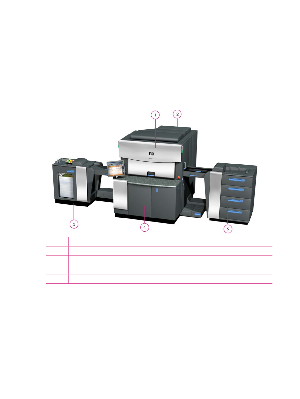
The press consists of five basic elements: the printing engine, ink cabinet, utility cabinet, feeder, and
stacker.
Figure 2-1 HP Indigo 7000 Digital Press
1 Printing engine
2 Utility cabinet
3 Stacker
4 Ink cabinet
5 Feeder
6 Chapter 2 Product overview ENWW
Page 16
Press serial number
The press serial number is on the front of the press behind the front door.
Figure 2-2 Press serial number
7000_PREIPH-1-07
ENWW HP Indigo press 7
Page 17

General press specifications
Printing rate
Input job definition Press productivity
Color
Job type
A4 (1/0) 14,400 7,200
A4 (4/0) 7,200 14,400
A4 (1/1) 7,200 7,200
A4 (4/4) 3,600 14,400
1
1
(number of color separations on side 1 / number of color separations on side 2)
A4 pages/hour Separations/hour (impressions/hour)
Up to seven colors are supported:
Option 1 - four process colors (CMYK - cyan, magenta, yellow, and black), plus 3 spot colors.
●
Option 2 - HP IndiChrome process (six color process), plus 1 spot color.
●
8 Chapter 2 Product overview ENWW
Page 18

3Safety
This chapter contains the following sections:
Overview
●
Warning signs and labels
●
Safety devices
●
Emergency power shutdown
●
Door interlocks and warning indicators
●
Attention lights
●
Maintenance safety and emergency procedures
●
Combustible and flammable liquids and fumes
●
ENWW 9
Page 19

Overview
The safety information and procedures described in this chapter apply to operators and other personnel
working on or near the HP Indigo 7000 Digital Press. The safety procedures cover the press and the
area immediately surrounding the press.
Use the following guidelines:
The press must only be operated by personnel trained by HP or its authorized agents who are
●
thoroughly familiar with all the safety and maintenance procedures of the press.
Before you attempt to use the press, read and understand the safety procedures, including
●
environmental protection procedures.
NOTE: Call a customer care center for service and repair of the press. Do not attempt to service or
repair the press.
The HP Indigo 7000 Digital Press is NRTL approved and marked for use in the USA and
Canada.
Notice for the European Union:
This product complies with the following EU directives:
The Low Voltage Directive 2006/95/EC
●
The Machinery Directives 2006/42/EC
●
The EMC Directives 2004/108/EC
●
Compliance with these directives implies conformity to applicable harmonized European standards
(European Norms) which are listed on the Declaration of Conformity issued by Hewlett-Packard for this
product or product family.
The Declaration of Conformity can be found at www.hp.com/go/certificates
10 Chapter 3 Safety ENWW
Page 20
Warning signs and labels
Warning labels on the press
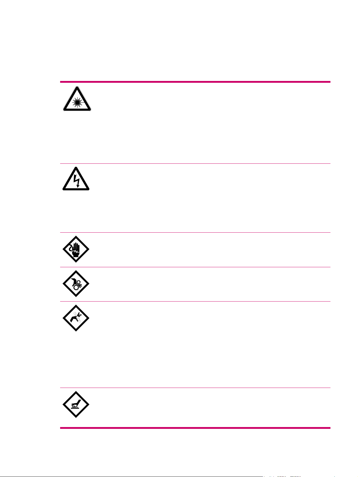
The following symbols appear on warning labels on the HP Indigo 7000 Digital Press:
Laser Hazard
DANGER. Invisible laser radiation may be present when doors are open and interlocks
are defeated. Avoid direct exposure to beam.
Laser Radiation
The lasers in the press emit radiation in the invisible range. The laser unit in the writing
head is enclosed in a protective housing and permits exit of the beam only at the writing
head window (aperture) to the PIP. Do not insert or allow any reflective objects to be
inserted in the path of the writing head window. Do not attempt to clean the writing head
window or look into the writing head window while the unit is operational.
Electrical Hazard
HAZARDOUS VOLTAGE. Will cause severe or fatal injury. Apply Lockout procedure.
Electrical Hazards
Before you start any maintenance procedure that involves an electrically powered
subsystem, make sure the subsystem is disconnected. If you are not sure that the
subsystem is turned off, turn off the main power switch. Always follow the lockout
procedure.
Live Current Hazard Alert
LIVE PARTS. Will cause severe or fatal injury. Apply Lockout procedure.
Entanglement Hazard Alert
WARNING. Open gears and mechanical parts. Can trap hands, fingers, clothing, and
cause serious injury. Stay well clear.
Pinch Hazard Alert
WARNING. Pinch points between rollers, wheels, and other parts can trap hands,
fingers, clothing, and cause serious injury. Stay well clear.
Mechanical Hazards
The press has a number of rotating parts and gripping devices (drums, gears, grippers,
and so on). Exercise special care when performing any maintenance work around these
parts. All repairs must be performed only by authorized customer engineers.
Do not climb into the substrate input or substrate exit for any reason. Doing so could be
dangerous.
Hot Surface Hazard
WARNING. Hot surface. Can cause burns. Do not touch.
Heat Hazards
ENWW Warning signs and labels 11
Page 21

The blanket and ITM drum become very hot during normal operation of the press, with
temperatures up to 110°C (230°F). Do not touch the ITM drum or external heater with
bare hands. Carelessness may cause burns. Wear thermal insulated gloves. Remove
old blankets with needlenose pliers.
The following warnings also appear on the press:
CAUTION! To reduce the risk of electric shock, the main disconnect should be locked in the off position before
servicing.
DANGER. Invisible laser radiation may be present when open and interlock defeated. Avoid direct exposure to
WARNING: Hazardous moving parts.
WARNING: Hazardous Voltage. Can cause damage.
WARNING: Hot surface. Can cause burns. Do not touch.
Emergency Stop Button
HIGH LEAKAGE CURRENT: Earth connection essential before connecting supply
MAIN EARTH CONNECTION LOCATED ON MAIN CHASSIS.
Warning signs
Post warning signs that clearly emphasize the dangers involved in operating and maintaining the press.
The following warnings are recommended:
This press is to be operated by properly trained and qualified operators only.
●
Do not wear ties, other loose clothing, or loose jewelry when operating and maintaining the unit.
●
Flammable vapors from heated imaging oil may be present!
●
No smoking, open flame, or sources of ignition allowed!
●
beam.
Make sure that the room is properly ventilated at all times. See the HP Indigo 7000 Digital Press
●
Site Preparation Guide.
Danger of pinching and crushing from moving press parts!
●
Keep hands away from moving press parts.
●
Access to Main Power switch must remain free at all times.
●
Do not operate the press with doors open.
●
Ink and imaging oil are irritating to eyes and skin. Use rubber gloves.
●
ITM drum and blanket are hot.
●
External heating lamps are hot.
●
Read and understand the material safety data sheets (MSDS) for consumables used with the press.
●
12 Chapter 3 Safety ENWW
Page 22

Placement of warning labels
Warning labels are placed in various locations on the press. Many of the warning labels on the press
are behind doors or covers and on parts that may be accessible only to authorized service personnel.
ENWW Warning signs and labels 13
Page 23

Safety devices
Material safety data sheets (MSDS)
MSDS are supplied for consumables, including the different HP ElectroInks, imaging oil and the imaging
agent, adhesion promoters, and adhesion promoter test fluids. Keep the MSDS readily available in the
work area. Read and consult them for your personal protection. Keep the MSDS in a protective plastic
cover.
Fire extinguishing equipment
The HP Indigo 7000 Digital Press generates combustible fumes and is also internally heated, a danger
of fire exists. Take the following precautions:
Position fire extinguishers in visible locations within 7.6 m (25 ft) of the press and any flammable
●
or combustible material storage areas.
Require regular inspection of the fire extinguishers (at least annually) and have designated
●
employees trained in their use. Employees should be retrained at least once a year.
Eye wash stations
The HP Indigo 7000 Digital Press uses inks and imaging oil that may be irritating to skin and eyes. In
extreme cases of exposure, these may cause blindness. Take the following precautions:
Install eye wash stations within 7.6 m (25 ft) of areas where the ink and imaging oil are handled,
●
dispensed, or stored.
Provide eye wash liquid at eye wash stations (available from most safety supply companies) that
●
complies with ANSI standard Z358. 1–1990.
Use safety glasses with side-shields and rubber gloves when handling ink and imaging oil (nitrile
●
disposable gloves are recommended).
Noise levels
During printing, the operator is exposed to a maximum of 80 dBA of audio noise with all service doors
and covers closed.
Heat insulating tools
The blanket, ITM drum, and external heating lamps become very hot during normal operation of the
press, with temperatures up to 165°C (355°F). Touching these parts could cause burns. Take the
following precautions when you work near the ITM drum or when you are replacing the blanket:
Wait until the drum cools to below 60°C (140°F) before performing maintenance procedures.
●
Do not place hands on the moving blanket. Use a tool to grip the blanket metal bar.
●
Electrical safety
The HP Indigo 7000 Digital Press must be properly grounded at all times. Before operating the unit,
ensure that it is grounded in conformance with the electrical code standards for your country/region (see
the HP Indigo 7000 Digital Press Site Preparation Guide for recommendations). If in doubt, check with
a licensed electrician or with your customer care center.
14 Chapter 3 Safety ENWW
Page 24

WARNING! Do not operate the press if it is not properly grounded. Perform a weekly check of
grounding cables.
If a cable has to be disconnected or reconnected during a maintenance procedure, you must electrically
turn off and lockout the press. Turn off the press by using the main power switch.
ENWW Safety devices 15
Page 25
Emergency power shutdown
The following can turn off all or some electrical power to the press:
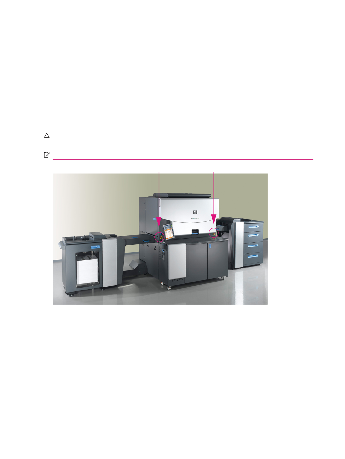
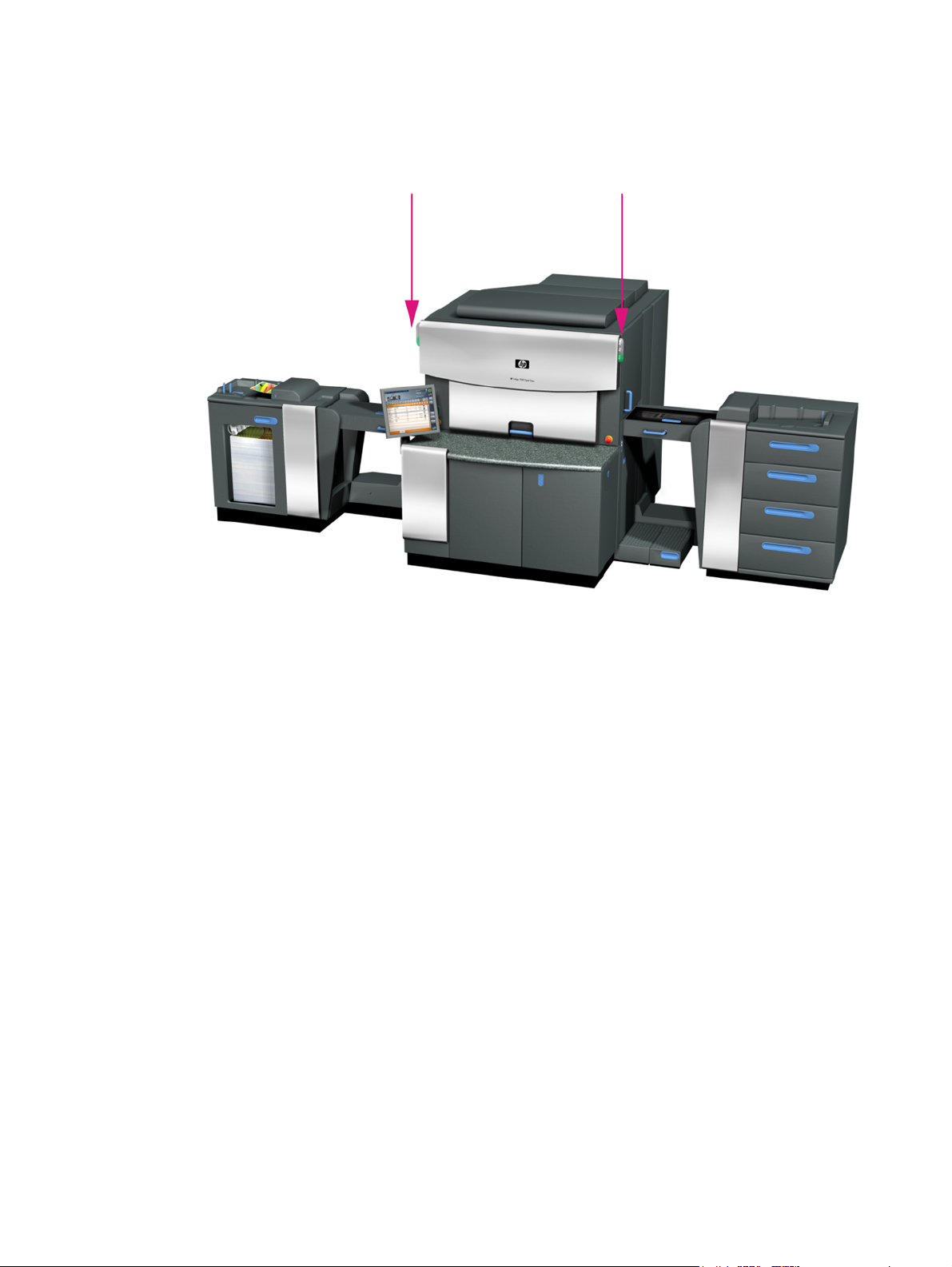
Emergency Stop buttons: In an emergency, press one of the red Emergency Stop buttons to
●
stop all mechanical movement in the main engine.
Red Emergency Stop buttons on a yellow background are located at both sides of the front door,
and in other prominent locations on the press. When pressed, the button stops the press, and turns
off electrical power to most system components.
To turn off power: press the button down.
◦
To restore power: rotate the button clockwise to release.
◦
CAUTION: Some press components continue to receive power after an Emergency Stop button is
pressed.
NOTE: Pressing an Emergency Stop button during printing can cause damage to the PIP and blanket.
Figure 3-1 Emergency Stop button on right and left sides of front door
16 Chapter 3 Safety ENWW
Page 26
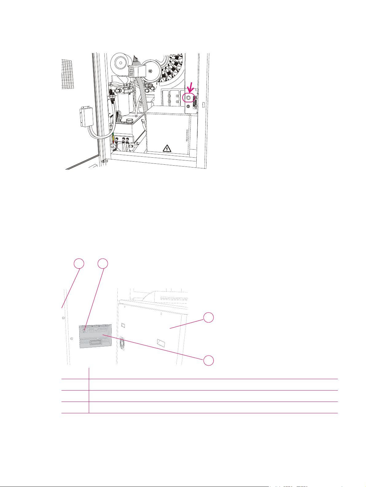
Figure 3-2 Emergency Stop button behind rear utility cabinet door
U
T
I
L
_
C
A
B
I
N
E
T
-
f
g
i
Main supply disconnect switch: The main supply disconnect switch is permanently connected to the
press via a conduit. A lockable disconnect device incorporated in the fixed wiring must be readily
accessible. The device must be rated according to the specifications shown in the HP Indigo 7000 Digital
Press Site Preparation Guide. This is an isolating device, which can be locked in the Off position to avoid
an unexpected startup or release of electrical power during servicing or maintenance.
Main power switch: The main power switch is located at the rear of the press. Access the main
●
power switch through the opening near the rear door. Raise the switch cover. Rotate the main
power switch to the left position to turn off all electrical power to the press engine.
Figure 3-3 Main power switch
12
P
R
E
I
P
H
_
0
1
7
6
A
-
f
i
g
1 Rear utility cabinet door
2 Main power switch at exit side, behind stacker unit
3 Stacker unit
4 Switch cover
3
4
ENWW Emergency power shutdown 17
Page 27
CAUTION: Always maintain free access to the main power switch, so that power can be immediately
turned off in an emergency.
The main power switch does not disconnect power to the power distribution unit (PDU).
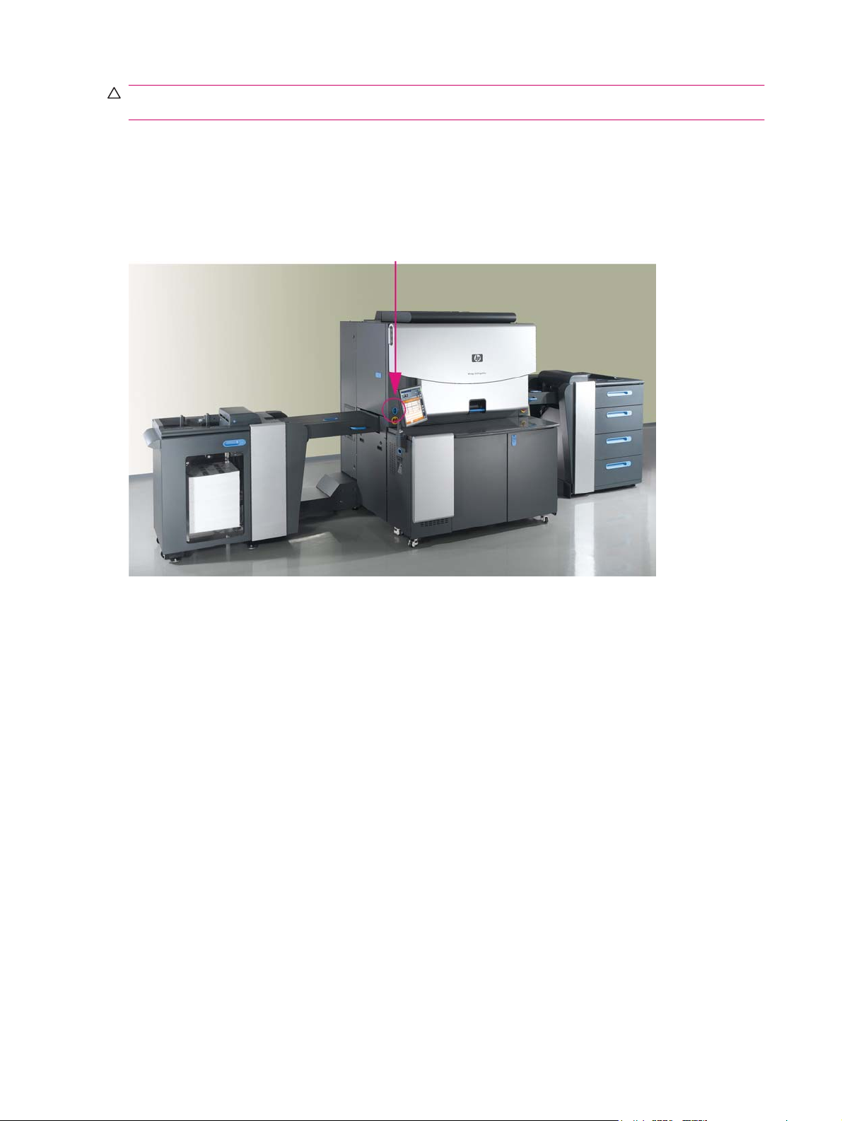
Power Enable switch: The Power Enable switch is located on the upper left side of the press. The
●
switch turns off power to the press engine subsystems, except for the computer and ink cabinet.
To turn off power, put the Power Enable switch in the off position. To restore power, put the Power
Enable switch in the on position.
Figure 3-4 Power Enable switch
18 Chapter 3 Safety ENWW
Page 28

Door interlocks and warning indicators
Door interlocks
The HP Indigo 7000 Digital Press has interlocked doors and covers that stop the press and turn off
electrical power to system devices when these doors and covers are opened.
WARNING! Access to, and use of bypass keys is restricted to specifically trained and authorized
personnel. Do not disconnect or override any of these safety devices.
The following doors and covers are interlocked:
Stacker Printing engine Feeder
• Stacker top cover • Upper feed door • Feeder drawers
• Stacker front door • Lower feed door • Feeder upper feed door
• Ink cabinet door (disables air
compressor to ink cans only)
• Front door • Feeder vertical access door
• Bridge
Cleaning ECN door
• External heater cover
• Rear utility cabinet door
• Feeder to cover frame
If any of the doors or covers are opened, the interlock is activated and prevents operation of most
devices, such as the high-voltage power supply and the main motor. Opening a feeder door will not turn
off power to all parts of the feeder.
When you open an interlocked door :
The press status changes to Off.
●
The schematic illustration indicates that the door is open,
●
All opened interlocked doors and covers are indicated by• an open lock icon in the user interface.
ENWW Door interlocks and warning indicators 19
Page 29
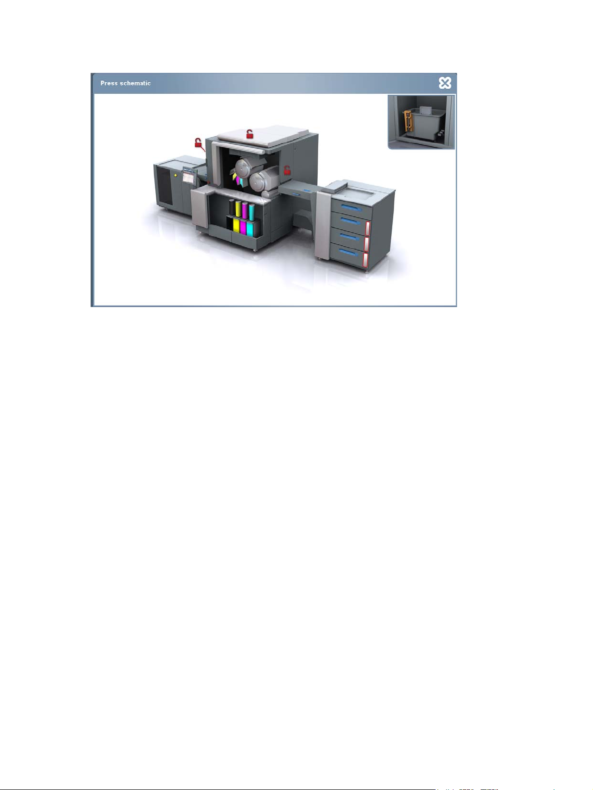
Figure 3-5 Press schematic showing open interlock doors
20 Chapter 3 Safety ENWW
Page 30
Attention lights
Attention lights are located on the input and exit sides of the printing engine.
Figure 3-6 Attention lights
Attention lights consist of three colors that indicate the following when lit:
Green light:
●
Always on in Ready state
◦
Flashing in Printing and Getting Ready states
◦
Yellow light:
●
Always on for all errors and for warning LEDs
◦
Warnings flagged:
An ink can is empty
◦
Conductivity in one ink tank is high/low
◦
Color adjustment is needed
◦
Print cleaner is needed
◦
Cooler drain is almost full
◦
Stacker is 90% full
◦
Only 10% of substrate is left in the feeder
◦
Red light:
●
Flashing when the bypass key is inserted, and a buzzer will sound before the press starts to
◦
rotate.
ENWW Attention lights 21
Page 31

CAUTION: A flashing red light indicates that the bypass key is inserted, and a buzzer will sound before
the press starts to rotate.
22 Chapter 3 Safety ENWW
Page 32

Maintenance safety and emergency procedures
Standby status
Put the press in Standby by pressing the Standby button on the touch screen when the system is not
required to print, or is unattended. The press automatically goes into Standby after it has remained idle
for more than 20 minutes.
Inching button
Use the Inching button in maintenance procedures that require inching the drums. If any interlocked
doors are open, the press returns to the off state. The Inching button is enabled when the upper feed
sliding window is opened. During inching, the press is in Standby.
Figure 3-7 Inching button (feed side)
Inch-safe method
WARNING! Do not perform maintenance on rotating parts (such as drums) with a hand on a moving
part while the press is on slow roll (for example, pressing the Inching button).
Health and safety regulations require that you use the inch-safe method for maintenance procedures
where the PIP, ITM, and impression drums are required to rotate:
1. Press an Emergency Stop button to put the press into an inactive state with the power on.
2. Perform the necessary procedure (for example, cleaning).
3. Release the Emergency Stop button by rotating it. Press the Inching button to inch the press.
Immediately press an Emergency Stop button to put the press into a safe state before continuing
maintenance.
4. Continue inching the press, stopping the press (putting it into an inactive state), and servicing the
press part until the job is complete.
ENWW Maintenance safety and emergency procedures 23
Page 33

Press lockout procedure
Health and safety regulations require that you use the following lockout procedure before performing
maintenance procedures that do not require drum rotation.
Lockout means either locking an energy-isolating device (for example, a fuse box) to prevent the
activation of the press, or unplugging the press, with the plug under the exclusive control of the person
performing the service or maintenance.
Use the following lockout procedure whenever there is any risk of unexpected press activation:
1. Disconnect the press from all sources of electrical power by using the Main Power Supply
Disconnect switch (see
2. Lock the isolator switch in the off position to avoid an unexpected startup or release of electricity.
3. Turn off the external Uninterruptable Power Supply (UPS).
4. Allow 20 seconds for residual stored energy to dissipate after the press is turned off.
5. Before starting maintenance or servicing, use a power tester to ensure that points that are live
when the press is in normal operation are no longer live.
Figure 3-3 Main power switch on page 17).
24 Chapter 3 Safety ENWW
Page 34

Combustible and flammable liquids and fumes
Because the imaging oil used by the HP Indigo press is combustible (USDOT Class 3A), use the
following safety procedures:
Operate the press in a well-ventilated room (see the HP Indigo 7000 Digital Press Site Preparation
●
Guide). The press is equipped with ventilation fans. If they are not functioning, the unit enters an
error state and the press becomes inoperable.
Do not smoke or introduce an external source of ignition (such as pilot lights, open flames, stoves,
●
heaters, or halogen lights). Avoid creating sparks (static, electrical, or mechanical) or introducing
any spark-producing equipment within 7.6 m (25 ft) of the press.
Clean spills immediately after they occur, and dispose of dampened cleaning materials promptly
●
and properly in accordance with local regulations.
Isopropyl alcohol (IPA)
IPA is a highly volatile and flammable liquid (USDOT Class 1B). Do not apply it to hot surfaces or allow
its use near an open flame or sources of electrical sparks.
Use IPA for cleaning specified parts only. Clean with IPA only when the printing engine is off. When you
use IPA, wait two to three minutes after application to allow the IPA to evaporate before proceeding. If
you cannot tell if the IPA has evaporated, use your finger to feel for wetness.
Handling and storing imaging oil, inks, and IPA
Take the following precautions when handling or storing imaging oil, inks, and IPA:
Avoid fire hazards by storing imaging oil, inks, and IPA in fireproof cabinets or a special combustible
●
liquids storage room.
Allow only trained personnel to handle imaging oil, inks, and IPA.
●
Keep containers tightly closed at all times. If a container appears damaged, transfer the contents
●
to a dry, clean, and suitable container that can be tightly sealed.
When handling imaging oil and inks, wear safety glasses with side shields, long-sleeve overalls,
●
and protective gloves as indicated on MSDS.
Keep MSDS in solvent-proof envelopes at the press.
●
Carefully drain the air conditioner sump tank. Use a suitable receptacle and avoid splashing.
●
Do not ingest imaging oil, inks, IPA, or any waste fluids.
●
Refer to local combustible material handling regulations.
●
Disposing of consumables and cleaning materials
Dispose of the consumables and cleaning materials that you use in accordance with applicable
regulations. Consult with your local authorities to determine the correct manner in which to dispose of
the following wastes:
Process oily waste bottles
●
Imaging oil and ink
●
ENWW Combustible and flammable liquids and fumes 25
Page 35

Empty HP ElectroInk containers
●
Charge roller
●
Blankets
●
PIPs
●
Cleaning wipes dampened with imaging oil
●
Lint-free wipes or tissue paper contaminated with ink
●
Contaminated chemical-resistant gloves
●
Empty imaging oil containers
●
Oil filters
●
Ozone filters
●
NOTE: For disposal of items other than those listed above, contact your local customer care center.
Waste bottles
Two bottles used to store waste are located in the lower service door at the rear of the press. These
bottles are identified as follows:
Waste bottle #1—Process oily waste
●
Waste bottle #2—Water waste
●
Figure 3-8 Waste bottles (in lower service door at press rear)
12
L
O
W
E
R
_
U
T
I
L
_
D
O
O
R
1
-
f
i
g
1 Water waste bottle
2 Process oily waste bottle
26 Chapter 3 Safety ENWW
Page 36

Additional information
It you have any questions regarding safe operation of the HP Indigo 7000 Digital Press, do not continue
operation without contacting a customer care center. Additional MSDS are available upon request from
your customer care center.
ENWW Combustible and flammable liquids and fumes 27
Page 37

28 Chapter 3 Safety ENWW
Page 38

4 Operating the press
This chapter contains the following sections:
Turning the press on
●
Using the press
●
Using the control panel
●
Turning the press off
●
ENWW 29
Page 39

Turning the press on
1. Make sure the HP Indigo press Production Manager is turned on and active prior to turning the
press on.
2. On the press, raise the switch cover and turn on the Main Power switch at the rear of the press
3. Wait for the HP Indigo 7000 Digital Press software to appear on the screen (this can take several
minutes),
4. Push the Power Enable switch on the exit side of the press.
The press is now in Standby state.
Figure 4-1 main Power switch at press rear
12
P
R
E
I
P
H
_
0
1
7
6
B
-
f
i
g
1 Main power switch
2 Switch cover
Figure 4-2 Power Enable switch
30 Chapter 4 Operating the press ENWW
Page 40

Using the press
1. Make certain that all the subsystems are assembled on the press and that end of day routines were
performed the previous day.
2. Put the press in Ready status. On the touchscreen, touch Get Ready. The press drums begin to
roll and the various subsystems power up. When the preset conditions are met, the press status
changes to Ready.
3. Load the substrate type for the first job to be printed (see
on page 69).
4. Load the job (see
5. Click Print or Proof.
6. Remove the printed sheets from the stacker. Check the output placement, color, etc. adjust if
necessary (see
7. When the job has finished printing, the press goes to Standby status.
8. When you have finished work for the day, turn the press off.
Printing jobs on page 41)
Editing job properties on page 43)
Loading substrate into the feeder
ENWW Using the press 31
Page 41

Using the control panel
The control panel is the main window from which you control the entire operation of the press.
Using the software
The software is the main screen from which you control the entire operation of the press.
Touch the required button or icon displayed on the screen to select an option. Some components are
read-only and are not sensitive to touch.
The main screen includes the following components which are always visible.
The control panel
●
Working area
●
The control panel
The control panel includes the following components:
1 Small press schematic
1
2
3
4
2 Print job panel
3 Main toolbar
4 Printing controls
Small press schematic
The small press schematic indicates the press status.
32 Chapter 4 Operating the press ENWW
Page 42

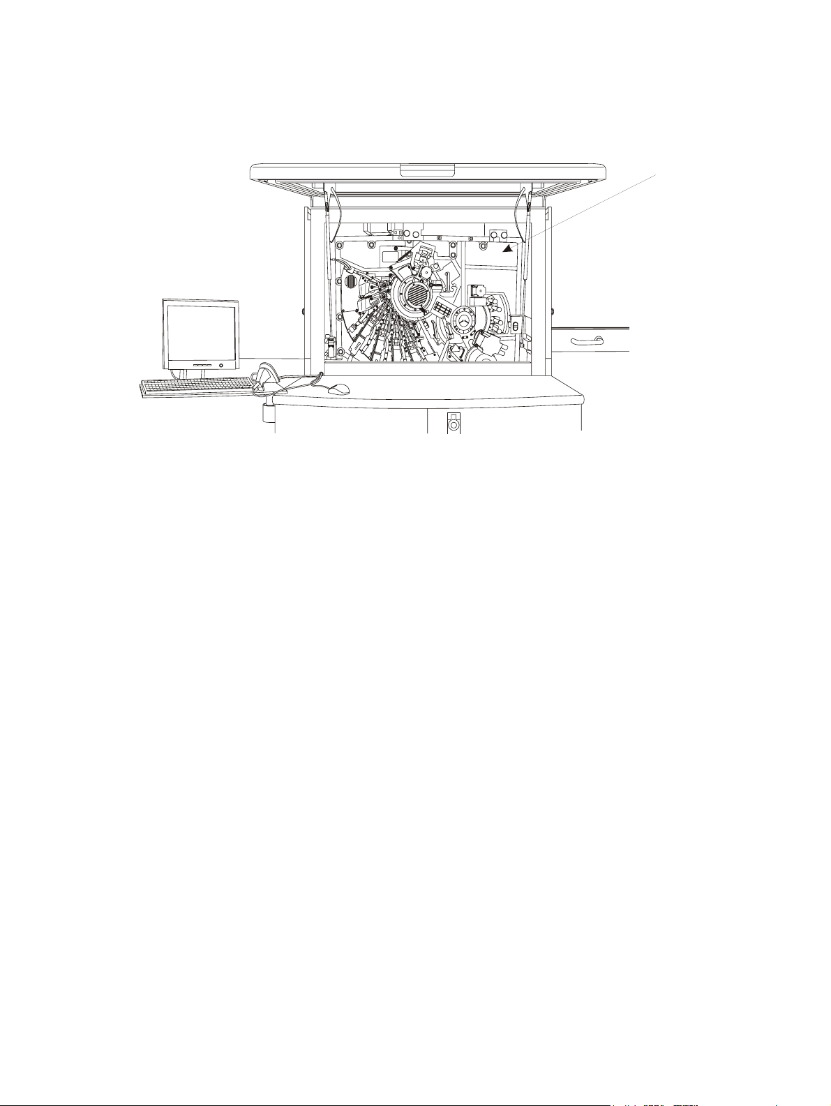
Using the Press Schematic
On the Main Menu, select Press Status, and Schematic.
The large Press Schematic panel is displayed indicating the current status of various parts of the press.
In the Press schematic panel, touch the various press parts to open the relevant part panel.
Figure 4-3 Press Schematic
Print job panel
The print job panel shows properties for the current job:
●
●
●
●
●
●
●
●
●
Touching the current job area opens the Copy/Sheet progress details for the current job.
Touching the next job area opens the Job Properties window for the next job.
Job name
Substrate name
Thumbnail of current job — select to display a full preview of the job
Number of sheets in the job
Number of copies printed and number of copies to be printed
Time left for the current job to finish printing
The next job to be printed
The status of the next job
Thumbnail of next job — select to display a full preview of the job
ENWW Using the control panel 33
Page 43

Main toolbar
The main toolbar is used to access the main menu and frequently used processes. The selection
appears in the working area.
The main toolbar includes the following buttons:
●
●
●
●
●
Main Menu — Enables access to all processes
— Displays the home window, and closes the current window.
Paused Processes — Allows you to switch between multiple paused processes. When more than
one application is paused, the number of paused processes is displayed in brackets. Touch the
arrow to open the drop-down list, and select a paused process.
— Opens a menu with additional main toolbar buttons, including customized buttons. This
button can be toggled to show or hide the menu.
— Changes to ToolTip mode. ToolTip mode displays the relevant tooltip when touching a
control button, and will not perform the relevant operation. This button can be toggled.
●
Print controls
The print controls are used to operate the press and to print jobs. The print controls also show the press
state.
— Opens the relevant help page for the current window in the working area.
34 Chapter 4 Operating the press ENWW
Page 44

1
2
3
4
5
6
1 Press state indicator
2 Error and warning indicators
3 Print buttons
4 Press status selector
5 Pause selector (idle)
6 Mode buttons
Press state indicator
Different press functions are possible only at defined press states.
The following press states exist:
Print
●
Getting Ready
●
Ready
●
Standby
●
Off
●
ENWW Using the control panel 35
Page 45

Error and warning indicators
The error and warning indicators display the number of unacknowledged messages. Touch the buttons
to open the list of the latest messages.
Print buttons
The print buttons control the operation of the press and jobs.
The following print buttons are available:
Print — Prints a single job.
●
When the press is in print state, this button changes to Pause. Touching this button, pauses the
job currently printing.
Proof — Prints a proof to the sample tray.
●
Sample — Prints a sample copy to the sample tray. While printing many copies of a job you cannot
●
print a proof, but you can print samples to check that print quality remains as good as the original
proof. Sample copies are not included in the number of copies for a job.
End Job — Ends the current job, and starts the next job.
●
Abort — Terminates the current job and stops printing.
●
Get Ready / Standby — Moves the press state from Standby to Ready; from Ready to Standby;
●
or from Get Ready to Standby.
NOTE: When working on a press with multiple stackers, all the print buttons are displayed with a
buzzer icon, and the controls are disabled prior to printing. Touching any print button activates the buzzer
alarm, indicating that the press is about to rotate at full speed. The print buttons are then enabled, and
the buzzer alarm stops
Mode buttons
The mode buttons control the print mode and the press mode when job printing is completed.
The mode buttons include:
●
●
At the completion of all print jobs in the print queue:
Idle — The press continues to rotate and moves to Pause state
◦
Suspend — The press stops rotating and moves to Ready state.
◦
36 Chapter 4 Operating the press ENWW
Page 46

At the end of each print job in the print queue:
Continuous — The press prints the next job automatically without stopping.
◦
Step — The press moves to Ready state, and only continues to next job when Print button is
◦
touched.
Working area
The working area of the touchscreen displays the currently running process. The processes are color
coded according to predefined groups to enable easy recognition. For examples green background
indicates wizards.
Navigating in the working area
The working area can include its own toolbar to enable navigation in the current process. Use the main
menu or main toolbar to navigate to other processes.
Virtual keyboards
A virtual keyboard appears when touching a button that requires text input. A virtual numeric keypad
appears when touching a button that requires number input.
ENWW Using the control panel 37
Page 47

Turning the press off
1. On the touch screen Main Menu, select Options, and Shut Down Computer. The Shut Down
Computer window appears.
2. Select Shut down the computer. Wait for the computer to completely shut down, this can take a
few minutes.
3. Turn off the Main Power switch at the rear of the press. The system is now shut down.
38 Chapter 4 Operating the press ENWW
Page 48

5 Job handling
This chapter contains the following sections:
Managing jobs
●
Printing jobs
●
Job maintenance
●
ENWW 39
Page 49

Managing jobs
Jobs are produced on the HP Indigo Production Manager, and sent to the press. On the press, Jobs
are managed using the Print Queue window. From the Print Queue you can view the status and
properties of all jobs, including:
The jobs currently printing
●
The jobs requiring preparation
●
Held jobs
●
Retained jobs saved in the system for a limited period of time
●
You can also view the job properties for each individual job.
Print Queue
The print queue is the default window in the touch screen working area. It shows the list of jobs to be
printed. Each job also contains information about the job parameters. Additional information about a
selected job can be seen by touching the Properties button.
Figure 5-1 Print Queue
40 Chapter 5 Job handling ENWW
Page 50

Printing jobs
To print jobs:
Load jobs in the Print Queue. The position of a job in the list depends on urgency, substrate type,
●
substrate thickness, number of colors in the job, or other job properties.
Arrange the jobs in the list to facilitate the workflow. For example, all jobs that use the same
●
substrate type or all jobs that use the same fifth and sixth color should be grouped and printed
consecutively.
Jobs are loaded and managed using the HP Indigo Press Production Manager.
Stage 1: Loading jobs
From the HP Indigo Production Manager, load jobs to the Loaded Jobs list. There are several ways to
load jobs to the list. Refer to the HP Indigo Production Manager user guide for details.
Make certain the job properties, number of copies, print range, and screen ruling are defined as
●
required.
Modify the properties if necessary. For more details, see
●
Stage 2: Proofing
1. In the Print Queue, select the job to print.
2. Click Proof. The press prints one copy of your job.
3. Evaluate the printed job.
Check for image placement in relation to the leading edge and to the left margin (see
●
5-5 Image placement on the sheet on page 45). Normally the image should be centered on
the narrow axis and 10 mm [0.39 inches] from the leading edge.
Check for color values. Compare with a previous print or a proof, if available. To modify color
●
values, use the Color Match tab or the Color Control in the Job Properties window.
Check image integrity, full ink coverage, right sheet sequence, and same image placement
●
for all jobs.
Editing job properties on page 43.
Figure
— For duplex jobs, check the front-to-back registration (see
registration on page 46).
— For multi-sheet jobs, make sure that the image placement is identical for all the job
sheets
— If necessary, move the job to the Held List, then open the Job Properties window,
click the Image Placement tab and make corrections.
Figure 5-6 Front-to-back
4. Print a second proof and evaluate it.
If there is a time delay between proof approval and the actual full run, print another proof
immediately before printing the full run, to make certain it matches the approved proof.
ENWW Printing jobs 41
Page 51

Stage 3: Printing the full run
1. Set the print mode on the control panel:
When it is set to Continuous, the job is unloaded at the end of the print run and the next job
●
in the Print Queue starts the print process.
When it is set to Step, the next job in the Print Queue is moved to the top of the Print Queue
●
and appears in the Now printing job field, but printing stops
Figure 5-2 Print mode selector
2. Change the press status to Ready.
3. Make certain the required substrate type for the subsequent job is loaded on the press.
4. On the control panel, click Print to print the full-run
42 Chapter 5 Job handling ENWW
Page 52

Job maintenance
Job maintenance activities are performed in the Job Properties window.
Job disposition and retrieval
Loaded jobs use large amounts of system space.
Do not keep unnecessary jobs on the system. The press will discard, save, save for a limited period of
time, or archive jobs that have been printed.
Define the disposition of a job after printing In the Job Properties window, General tab.
●
In the After Print Retain For section, type or select the period of time you need to retain a print
job.
To retrieve a retained job in the Job Manager window, click Job and Retain List.
●
Drag and drop the required job into either the Loaded Jobs list or the Print Queue.
Archive a job from the Job Manager window by clicking Job and Export. Save the job to a memory
●
storage device on the system, such as the DVD writer.
Retrieve jobs from the Job Manager window by clicking Job and Import. Access the required
●
directory or drive and select the job to be imported.
Editing job properties
Edit job properties in the Job Properties window.
Open the Job Properties window from the HP Press Production Manager—Press Job Manager. Rightclick a job in the Loaded Jobs panel, and select Job Properties.
The Job Properties window contains the following tabs:
General: Defines job related parameters such as number of copies, sheet range, duplexing, and
●
job retention.
Substrate: Used to define the substrate to be used for printing the selected job.
●
Stacking: Used to change stacking destination and the duplex orientation.
●
Image Placement: Used to change the position of images within the job.
●
Color Control: Used to change a job's color look-up table (LUT) - see below.
●
Color Match: Used to modify dot area and optical density of the separate colors.
●
ENWW Job maintenance 43
Page 53

Separations: Used for defining separations, screening, and ink order.
●
Linework and Resolution: Used to define resolution and linework settings such as adaptive
●
halftoning, line smoothing, and line thinning.
Figure 5-3 Job Properties—General
44 Chapter 5 Job handling ENWW
Page 54

Image placement
Corrections to image placement on the substrate for a specific job can be done from the Job
Properties window, Image Placement tab.
Correct the image placement in relation to the leading edge and the margins. Normally the image
●
should be centered on the narrow axis, and 10 mm (0.39 inches) from the leading edge.
For duplex jobs, you can correct the front to back registration.
●
Adjust identical image placement for multi-sheet jobs.
●
Figure 5-4 Job properties — Image placement tab
Figure 5-5 Image placement on the sheet
10 mm
(.39 inches)
XX
Image is centered
on the horizontal
axis (X=X)
ENWW Job maintenance 45
Page 55

Figure 5-6 Front-to-back registration
s
g
Front leading
2
1
Figure 5-7 Cross-run registration
Distance from left
margin to image is
equal throughout
the run
Front cross
marks
aligned with
back cross mark
Distance from leadin
edge to image is
equal throughout the
run
.
Editing job look-up tables (LUTs)
Job LUTs are used to change the printed dot size in relation to the dot size as defined in the original
graphics files. By editing LUTs, you can control the dot gain for every dot size individually.
46 Chapter 5 Job handling ENWW
Page 56

HP Indigo supplies several tailored LUTs, ranging from Linear to Chromalin, with Chromalin applying
the biggest dot gain. You can also create your own LUT or set a customized LUT as the default.
Figure 5-8 Different LUTs
yy
x
Chromalin Linear
x Dot size in graphic file
y Printed dot size
To create your own LUT, select Job Properties, and then select the Color Control tab. Use the Table
and Scales tab to modify the entire LUT, or change selected points.
Figure 5-9 Job Properties—Color Control
NOTE: LUT changes only apply to the selected job.
You can save the LUT to the LUT Library for use with other jobs.
You can control the 50 percent dot area from the job LUT panel.
ENWW Job maintenance 47
Page 57

To improve accuracy, adjust colors from the Color Control tab (Figure 5-9 Job Properties—Color
Control on page 47).
The solid, 100 percent optical density slider in the Job properties - Color Control window contains the
same parameter adjustments as those in the Job properties - Color Match window.
Color matching is used when you need to change the color intensity. Color matching is a fast but less
exact tool than LUT changes. With color matching, the entire gray scale shifts either up or down.
With color matching, you can define the new optical density value for the 100 percent dot area and for
the 50 percent dot area for each ink individually. Move the job to the Held Job list before attempting to
perform Color Match. These values are then saved as part of the job properties for future runs.
Figure 5-10 Job Properties—Color Match tab
Screening
Jobs can be printed with different screen rulings. The higher the screen ruling, the better the rendering
of detail.
Higher screen rulings are more demanding, because they require a more finely tuned press calibration.
Job screen can be defined in the Job Properties window, Separations tab.
HP Indigo supplies the following screen rulings:
Sequin — an average of 144 lines per inch (lpi), used for specific circumstances only
●
HDI-175 — an average of 175 lpi — default screen used for most jobs
●
HDI-180 — an average of 180 lpi
●
You can print a separation several times to enhance density.
48 Chapter 5 Job handling ENWW
Page 58

HP Indigo supplies you with alternative color order to support transparency printing.
Figure 5-11 Job Properties — Separations tab
Inks “double-hit” printing
Some Ink Mixing System inks require double-hit printing in order to achieve the required color saturation,
and this feature performs double-hit printing without screening artifacts (patterns).
The press will double-hit only the solid and high-saturation gray levels.
To access the double-hit feature:
ENWW Job maintenance 49
Page 59

Double-hit printing can be defined from the Job Properties window, Separations tab. Check the X2
box for the required color.
Figure 5-12 Double Hit check box
50 Chapter 5 Job handling ENWW
Page 60

Linework and resolution
Modify linework and resolution to print thinner lines and smoother fonts at a higher definition. Job
linework and resolution can be defined in the Job Properties, Linework and Resolution tab.
Check Adaptive Halftoning to smooth edges on gray-level areas
●
Check Line Smoothing to smooth lines in 400 dpi and 600 dpi jobs
●
Check Line Thinning and type a value in microns or use the slider to choose value
●
Figure 5-13 Job Properties — Linework and resolution tab
ENWW Job maintenance 51
Page 61

52 Chapter 5 Job handling ENWW
Page 62

6 Color management
This chapter contains the following sections:
Calibrating the press colors
●
Color Calibration procedures
●
Defining substrate-related color parameters
●
Selecting a workflow for full color calibration and substrate-related parameters
●
ENWW 53
Page 63

Calibrating the press colors
There are two ways of calibrating the press colors:
Short color calibration - offers high speed and economy.
●
Full color calibration - offers high accuracy and flexibility.
●
The short color calibration procedure is used to guarantee color repeatability between runs on the press.
It allows you to set the density of the solid ink layer and the density of three grey levels..
●
It fine tunes the compensation process for each PIP since PIP deterioration over time is a source
●
of color inaccuracies.
It is triggered automatically:
●
After a PIP replacement
◦
Every 10,000 impressions per substrate type, unless bypassed by the operator.
◦
Perform the short color adjustment procedure after replacing the blanket.
Perform the full color calibration when a particular screen, ink or substrate is changed.
The full color calibration calibrates 15 points on the dot gain curve.
The full color calibration is operated automatically every 20,000 impressions, or via a wizard.
54 Chapter 6 Color management ENWW
Page 64

Color Calibration procedures
To perform the short or full color calibration procedure:
1. On the press software menu, select Print Quality. The Print Quality panel opens.
2. Touch Color Calibration. The Color Calibration wizard opens.
3. Select the Short or Full color calibration type,
4. Select a method to run the calibration — Skip to print uses default substrate, screening and ink
parameters to run the calibration. Step by step allows you to customize the calibration parameters.
NOTE: When performing a Step by Step calibration, choose a the same substrate or a substrate
from the same group as the calibration substrate.
Figure 6-1 Color Calibration Wizard
5. At the wizard Method step, select the Standard or Custom calibration method.
The Standard calibration method allows you to continue the calibration with no additional
●
options.
ENWW Color Calibration procedures 55
Page 65

The Custom calibration method allows you to choose to include the Velectrode calibration
●
and default parameters to overcome print quality issues, as well as modifying target optical
density of 100% ink coverage values.
Figure 6-2 Color Calibration method
6. Follow the wizard instructions to complete the calibration procedure.
56 Chapter 6 Color management ENWW
Page 66

Defining substrate-related color parameters
Different substrates can produce different color results. The ability to perform machine LUT generation
and color adjustment for each substrate increases the color accuracy for different substrates. Color
calibrations can be performed on almost all substrates.
Optical density of substrates
The optical density can vary between substrates even when using the same press parameters (such as
laser power and developer voltage).
A densitometer gives a lower reading on matte substrates, compared to glossy substrates, although
these substrates can appear identical to the human eye. Based on the densitometer reading, the press
adjusts the printing to a lower density on matte substrates than on glossy substrates.
You can define the optical density for each substrate by selecting the correct substrate gloss level:
Matte (0 < gloss < 12) — represents a group of uncoated and high-matte substrates
●
Semi-matte (12 < gloss < 25) — represents a group of high-quality matte and silk substrates
●
Glossy (gloss > 25) — represents all glossy substrates
●
The press calibrates the solid density according to the following table:
Substrate gloss
level
Matte
(0 < Gloss < 12)
Semi-matte
(12 < Gloss < 25)
Gloss
(Gloss> 25)
Yellow Magenta Cyan Black Orange Violet Green
0.9 1.1 1.1 1.2 1.3 1.1 1.1
1.0 1.3 1.3 1.5 1.65 1.3 1.3
1.1 1.45 1.45 1.75 1.9 1.45 1.45
NOTE: The optical density calibration of HP Indigo Ink Mixing System (IMS) inks is specified in the
HP Indigo Ink Mixing System file. Unlike other inks, the optical density of IMS inks does not change
automatically when changing substrate type, so the optical density of IMS inks must be changed
manually.
Defining a different substrate type (gloss level) automatically adjusts the optical densities.
1. Select Main Menu, Substrate, and Substrate List to open the Substrate List .
2. Select a substrate and touch Properties, then Edit to edit the substrate gloss level and color
calibration parameters.
ENWW Defining substrate-related color parameters 57
Page 67

3. In the Substrate List, select a substrate and click Assign to assign it to a feeder drawer.
Figure 6-3 Substrate List — Properties window
A substrate can inherit color calibration parameters from a different substrate defined in the system.
58 Chapter 6 Color management ENWW
Page 68

Selecting a workflow for full color calibration and substrate-related parameters
The full color calibration process updates the job look-up table (LUT). These tables reflect the current
press performance with regard to print quality. The LUT results may not be suitable for use if the LUT
generation is performed in non-optimal, or unstable conditions. You should therefore verify print quality
before performing the full color calibration. Verify the following for best results:
The first transfer is adjusted properly.
●
The substrate you are using is a well defined (type and thickness) calibration substrate, or is
●
attached to one.
No print quality defects exist—such as voids, streaks, or stains.
●
Because of potential variability in the results, you should avoid performing a full color calibration on a
blanket having less than 3,000 impressions.
Very high accuracy workflow
For a very high accuracy workflow, perform the following:
Define all substrates as calibration substrates.
●
In addition to the automatic calibrations, perform full color calibration several times a day (at least
●
every 10,000 impressions), before every long run, before any color-critical job, before every
important proof, and on all used screens.
High accuracy workflow
For a high accuracy workflow, perform the following:
Define two or three substrates as calibration substrates. Attach each of the other substrates to one
●
of the calibration substrates.
In addition to the automatic calibrations, perform full color calibration on a daily basis (at least every
●
20,000 impressions) and before every color-critical job on all screens and substrates used.
Normal accuracy workflow
For a normal accuracy workflow, perform the following:
Define one substrates as a calibration substrate. Attach all the other substrates to this calibration
●
substrate.
Let automatic calibration be performed.
●
If automatic calibrations are bypassed, perform full color calibration on the calibration substrate
●
and all used screens on a weekly basis
ENWW Selecting a workflow for full color calibration and substrate-related parameters 59
Page 69

Viewing last color calibration generation
The Color Calibration Status button in the Print Quality Panel displays the last color calibration
▲
results.
Figure 6-4 Color Calibration Results
Determining substrate type
Perform the following procedure to determine the substrate type (glossy, semi-matte or matte) and to
define OD values for different substrates, including plastic and transparent substrates.
1. Load a well defined substrate in the press. A high gloss substrate should be used. However, if it is
not available, use another substrate whose type is known (e.g. gloss, semi-matte, matte) and
defined.
2. On the Main menu, select Print Quality. The Print Quality Panel opens.
3. Click Color Calibration. The Color Calibration wizard opens.
60 Chapter 6 Color management ENWW
Page 70

4. Select Full calibration type, and run it Step by Step.
In the Substrate step, select the required substrate (the most used substrate on the press).
●
In the Method step, select Custom method, Use V-electrode, and Start with default
●
parameters.
Figure 6-5 Color Calibration wizard — Method step
5. Run the wizard and make sure that all colors pass the color adjustment procedure. Click Finish.
6. Load the required substrate on the press. Any unknown substrate type should be attached to the
calibration substrate in the substrate list.
7. Print 10 copies of the CATP job.
8. Measure the solid patches (J area) in the 9th and 10th copy of the CATP printout. Make sure to
measure on a white background, and calculate the average values. Note these values.
9. Check the measured values for each ink and compare to the values specified in the following table
(note that the specified gloss values are correct only for paper substrates):
Substrate gloss
level
Matte
(0 < Gloss < 12)
Semi-matte
(12 < Gloss < 25)
Gloss
(Gloss> 25)
Yellow Magenta Cyan Black Orange Violet Green
0.9 1.1 1.1 1.2 1.3 1.1 1.1
1.0 1.3 1.3 1.5 1.65 1.3 1.3
1.1 1.45 1.45 1.75 1.9 1.45 1.45
10. In the table, find the substrate type that most closely resembles the measured solid OD values.
ENWW Selecting a workflow for full color calibration and substrate-related parameters 61
Page 71

11. Click Main Menu, Substrate, and Substrate List. The Substrate List opens.
12. In the list, select the required substrate, then touch Properties, and Edit. The Substrate
Properties window opens.
13. In the substrate Type field, select the type that matches the measured solid OD values (gloss, semi-
matte, matte).
Figure 6-6 Substrate List — Properties window
14. Re-run the Color Calibration Wizard
15. Select Full calibration type, and run it Step by Step.
In the Method step, select Custom method, Use V-electrode, and Start with default
●
parameters.
62 Chapter 6 Color management ENWW
Page 72

Click Optical Density to open the Optical Density window. Verify that the OD values match
●
the values in the table according to the substrate type defined.
Figure 6-7 Optical Density window
16. Follow the wizard instructions to complete the calibration procedure. Make sure that all colors pass
Exceptions
If high color accuracy is needed, the exact solid OD values should be documented and changed
whenever the substrate is installed in the press.
●
●
If the color adjustment fails when adjusting the 100% OD values, verify that the ink parameters are
correct (density, conductivity, temperature).
●
●
the color adjustment procedure.
Do this by clicking the Setup button in the Short Color Calibration wizard or the Full Color
Calibration wizard.
The regular definitions (gloss, semi-matt, matt) are usually sufficient for best color performance.
Where the ink parameters are correct, and the color adjustment fails when adjusting the 100% OD
values, the problem is probably associated with the substrate type definition.
If the developer voltage is too low, select a glossier substrate type, if it is too high, select a less
glossy substrate type.
ENWW Selecting a workflow for full color calibration and substrate-related parameters 63
Page 73

64 Chapter 6 Color management ENWW
Page 74

7 Substrate handling system
This chapter contains the following sections:
Overview
●
Substrate specifications
●
Loading substrate into the feeder
●
Monitoring status of substrates in drawers
●
Defining substrate type
●
Operating and unloading the stacker
●
Defining stacker options
●
Clearing substrate jams
●
Maintaining the substrate transport system
●
ENWW 65
Page 75

Overview
This chapter describes substrate specifications, and management of each of the substrate transport
subsystems.
NOTE: Use only allowable substrates and substrate sizes as described below.
The basic processes in substrate handling are as follows:
Load substrates into the feeder.
●
Update the substrate definitions in the press software after you load a new substrate.
●
Unload the substrate from the stacker.
●
Control the substrate transport system through the press software.
●
66 Chapter 7 Substrate handling system ENWW
Page 76

Substrate specifications
Table 7-1 Allowable substrates — simplex and duplex
Substrate type Weight
Coated glossy or matte papers
Uncoated papers
Plastics (types qualified by HP Indigo) —
Transparencies (types qualified by HP Indigo must include a
non-transparent edge)
Table 7-2 Substrate size
Substrate parameter Parameter range
Length (process direction), simplex 210 to 482 mm (8.26 to 19 inches)
Length (process direction), duplex 420 to 482 mm (16.53 to 19 inches)
Width, simplex and duplex 279.4 to 330 mm (11 to 13 inches)
Thickness 0.07 to 0.41 mm (0.0027 to 0.015 inch)
Sheet length (or width) tolerance, simplex ±1.0 mm (±0.039 inch)
Parallelism — leading to trailing edge 0.4 mm (0.016 inch) maximum
Diagonal differences 0.6 mm (0.024 inch) maximum
80 to 350 g⁄m2 (55 lb text to 130 lb cover)
65 to 300 g⁄m2 (45 lb text to 110 lb cover)
—
Substrate storage
Paper is an organic matter and highly sensitive to relative humidity changes.
●
Allow your stock to adjust to the ambient conditions before using it.
●
Do not unwrap the substrate stack until it has reached room temperature.
●
Operate the press at a relative humidity range from 15 to 70 percent (non-condensing), and for
●
ambient temperatures ranging from 15 to 30° C (59 to 86° F).
Grain direction
Use long-grain sheets for substrates lighter than 170 g/m
●
Use short or long grain sheets for substrates between 170 g/m
●
●
2
g/m
(74 lb cover).
Use short grain sheets for substrate types heavier than 200 g/m
2
(115 lb text/63 lb cover).
2
(115 lb text/63 lb cover) and 200
2
(74 lb cover).
ENWW Substrate specifications 67
Page 77

Sheet trimming
Make sure that the sheets are trimmed correctly and are not stuck together before you load the
●
substrate in the feed drawer.
If necessary, trim the stack on two axes (top and left edges), and then fan the sheets before using
●
them.
Make sure the blade used to trim the sheets is sharp. Using a blunt blade will cause substrate jams.
●
Sheet size
When using a new substrate stack, verify that the sheet size is identical to the size defined in the
substrate list.
Make sure that the size of the sheets used in the drawer and the new sheets are identical.
68 Chapter 7 Substrate handling system ENWW
Page 78

Loading substrate into the feeder
Load substrates into the feeder.
To load a substrate:
1. Open a drawer on the feeder and place a small amount of substrate in it.
2. Position the substrate guides, taking care not to damage the edges of the substrate.
3. Fan the substrate before placing it in the drawer.
4. Add the rest of the required amount of substrate to the drawer, taking care not to exceed the
maximum level mark.
5. Close the drawer.
6. Update the substrate definition for the substrate drawer. See
on page 71.
You can use two drawers with the same substrate type. The press is designed to automatically
●
alternate between two drawers containing the same substrate in order to allow high press
utilization.
Defining substrate type
ENWW Loading substrate into the feeder 69
Page 79

Monitoring status of substrates in drawers
During printing you can monitor the status of the substrates loaded in the drawers.
From the Main Menu, select Substrate> Drawers.
▲
The Drawers window appears.
Figure 7-1 Drawers window
Use the Drawers toolbar buttons to access the substrate management windows.
NOTE: If the substrate loaded in the press and the substrate defined in the press software do not
match, then the substrate name and its relevant mismatched properties are displayed in red. In addition,
the measured properties are displayed in brackets.
70 Chapter 7 Substrate handling system ENWW
Page 80

Defining substrate type
When loading a substrate, define the type of substrate on the press. The system uses this information
to automatically adjust pressures and fine-tune colors.
To define a substrate:
1. On the main menu, click Substrate and Substrate List. The Substrate List window opens.
Figure 7-2 Substrate List window
2. Select a substrate from the list.
3. Click Assign, the Assign to Drawers window opens.
ENWW Defining substrate type 71
Page 81

4. Select a drawer and click Assign.
Figure 7-3 Assign to Drawers window
To add a substrate that is not listed:
1. In the Substrate window, click the List button.
2. In Substrate List, click Properties and New and define the parameters in the New Substrate
window .
Figure 7-4 New Substrate window
72 Chapter 7 Substrate handling system ENWW
Page 82

Operating and unloading the stacker
p
The three substrate paths in a stacker, are shown below.
Figure 7-5 Substrate transport
To top tray
From
printer
Stacker controls are shown below.
Pa
er stack
ENWW Operating and unloading the stacker 73
Page 83

Figure 7-6 Stacker control buttons
d
12
1
2
3
4
Door
Top cover
Sample tray
Proof button (by pressing this button, you get a sample sheet from the printer to check printing quality).
3
4
5
Door closed-stacker ready
PRESS
Door unlocke
PRESS
Stop printing-lift goes down
5
Door button
To open the stacker door:
1. Make sure the top LED is on. This indicates that the stacker is ready (is in operational mode).
2. Press the button once. The middle LED turns on and this unlocks the door.
3. Press the button again. The bottom LED turns on and the elevator is lowered.
4. The LED blinks until the elevator is completely down.
5. Open the door to access to the substrate stack.
Unloading a substrate stack
To unload a substrate stack from the stacker:
1. Open the stacker door.
2. Place the pallet jack below the elevator base in the stacker.
3. Attach the hold-down device.
74 Chapter 7 Substrate handling system ENWW
Page 84

4. Lift and pull out the stack.
5. Put in the second stacker base and close the stacker door. The elevator will rise to the top of the
stacker.
Figure 7-7 Hold-down device
1
g
i
f
-
4
A
3
_
1
K
1
C
S
A
T
A
E
E
E
S
_
L
R
2
3
ENWW Operating and unloading the stacker 75
Page 85

Defining stacker options
Adjusting stacker options
From the Main Menu, click Options, and Print Preferences to open the Print Preference window.
▲
In the Job Options tab check Forced destination, and click on the desired destination in the
●
stacker schematic:
In the Full Stacker tab choose:
●
— Maximum stacker capacity
— Full stacker policy options when full
In the Proof and Sample tab select Proof to stacker to send proofs to the stacker instead
●
of the proof tray.
In the Special Jobs tab choose the destination for the standard special jobs and for the color
●
calibration special jobs.
Figure 7-8 Print Preference — Job Options
76 Chapter 7 Substrate handling system ENWW
Page 86

Figure 7-9 Print Preference — Full Stacker
ENWW Defining stacker options 77
Page 87

Clearing substrate jams
A system warning indicator appears on the control panel and a warning symbol appears indicating the
location of a substrate jam when it occurs.
Substrate jams can occur:
In the feeder
●
On the vertical path
◦
At the feed head
◦
At the bridge
◦
At the external heating housing
●
●
At the perfector
At the cleaning station
●
Under the air knife
●
At the exit blanket ventilation
●
At the exit conveyor
●
At the stacker bridge and stacker
●
Figure 7-10 Substrate jam indicators on the press schematic (1 of 2)
Figure 7-10 Substrate jam indicators on the press schematic (2 of 2)
Removing substrate jam on the feeder
WARNING! Press an Emergency Stop button before you try to fix a substrate jam.
78 Chapter 7 Substrate handling system ENWW
Page 88

To clear a substrate jam from the feeder:
1. Open the appropriate doors, and if necessary, release the latch on the module to access the interior.
2. Carefully remove the substrate. Slowly pull the edge of the sheet.
Figure 7-11 Removing substrate jams from the feeder
Removing a substrate jam at the external heating housing
To clear a substrate jam at the external heating housing:
1. Open the press feed door.
2. Open the external heating housing sliding door.
3. Remove any jammed substrate.
4. Close the external heating housing sliding door and the press feed door. .
Removing substrate jam at the perfector
WARNING! Press an Emergency Stop button before you try to fix a substrate jam.
To clear a substrate jam at the perfector:
1. Open the press lower feed door and lower the duplex conveyor
2. Remove any jammed substrate in the duplex conveyor or perfector.
ENWW Clearing substrate jams 79
Page 89

3. Clean and check the eight perfector suction cups, and replace if necessary. Cup holders may be
rotated by hand for access.
4. Raise the duplex conveyor and close the press lower feed door.
Figure 7-12 Duplex conveyor in down position
1
g
i
-
f
R
O
T
C
E
F
R
E
P
_
R
O
Y
E
V
N
O
C
_
X
E
L
P
U
D
2
1
2
Perfector
Duplex conveyor in down position
Figure 7-13 Perfector suction cups
SUCTION_CUPS-0708-fig
Removing substrate jam at the cleaning station
Perform this procedure when a sheet is jammed between the PIP drum and the cleaning station.
Indications that this has occurred are as follows:
The sheet is not found in the exit conveyor, rotors, perfector, duplex unit, or on the blanket.
●
The cleaning station drips imaging oil.
●
The PIP is scratched.
●
To remove a substrate jam at the cleaning station:
1. Press an Emergency Stop button.
2. Remove the cleaning station blade and cleaning station.
80 Chapter 7 Substrate handling system ENWW
Page 90

3. Remove the substrate sheet that is jammed between the cleaning station and the PIP drum.
4. Reinstall the cleaning station, and cleaning station blade.
5. Close all doors and release the Emergency Stop button.
Removing substrate shreds under the PTE, exit roller and exit blanket
ventilation
Remove substrate shreds from the press when a sheet is torn during a substrate jam.
If you suspect that the whole sheet has not been removed after a substrate jam, check the space
between the air knife and the PIP:
1. Press an Emergency Stop button and open the front door.
2. Remove the PTE unit.
3. Remove the exit roller and exit blanket ventilation unit.
4. Access the PIP and remove any loose substrate shreds.
5. Re-install the PTE unit, exit roller, and exit blanket ventilation unit.
6. Close all doors and release the Emergency Stop button.
Removing substrate jam at the exit conveyor
WARNING! Press an Emergency Stop button before you try to fix a substrate jam.
To clear a substrate jam at the exit conveyor:
1. Open the press exit sliding window and lift up the exit cover.
2. Carefully remove jammed substrate.
ENWW Clearing substrate jams 81
Page 91

Figure 7-14 Exit cover
1
P
R
E
S
S
_
E
X
I
T
-
f
i
g
23
1
2
3
Exit cover
Exit sensor
Exit rollers
Removing substrate jam at the stacker bridge or at a stacker
WARNING! Press an Emergency Stop button before you try to fix a substrate jam.
To clear a substrate jam at the stacker:
1. Lift up the stacker top cover and the stacker substrate cover,
2. Carefully remove jammed substrate.
3. Open the left front door of the stacker to check the flipping wheels for jams. Pull out, and move the
knob to the open position to check for pieces of substrate.
82 Chapter 7 Substrate handling system ENWW
Page 92

Figure 7-15 Stacker top
1
S
T
A
C
K
E
R
_
T
O
P
1
f
i
g
1
2
Stacker cover
Stacker substrate cover
Figure 7-16 Stacker flipping wheels
2
12
5
Open
Close
S
A
C
T
K
F
_
E
R
I
P
L
P
I
N
_
G
H
E
W
S
f
i
E
-
L
&
g
4
1
2
3
4
Flipping wheels
Elevator tray
Stacker sensor (inside)
Knob
3
ENWW Clearing substrate jams 83
Page 93

Maintaining the substrate transport system
Clean the substrate path once a week as part of the weekly maintenance routine.
Cleaning the substrate path
Clean the following parts of the substrate path once a week as part of the weekly maintenance routine:
Input path
●
Printing engine
●
Exit path
●
Cleaning the input path
CAUTION: Wear safety glasses and gloves for this procedure. Use a lint-free wipe dampened with
IPA only for cleaning.
To clean the input path:
1. Go to Standby and press an Emergency Stop button.
2. Open each feeder drawer and unload the substrate.
3. Clean the bottom of the drawers, then reload the substrate.
4. Clean the vertical path. Thoroughly clean all sensors and rollers, then close the vertical module
and its access door.
5. Open the feeder top cover and clean the top of the vertical module, including the rollers.
6. Release the feeder top cover latch, and close the top cover.
7. Open the bridge cover and open the flap in the bridge multi-pick area.
8. Clean the multi-pick area, including all rollers and sensors.
9. Close the flap.
10. Clean the bridge, including the belts, rollers, and sensors.
11. Close the bridge cover.
Cleaning the printing engine substrate path
CAUTION: Wear safety glasses and gloves for this procedure. Use a lint-free wipe dampened with
IPA only for cleaning, unless noted otherwise.
To clean the printing engine substrate path:
1. Go to Standby and press an Emergency Stop button.
2. Open the upper feed sliding window , raise the bridge, remove the external heater lamps and
external heater cover.
84 Chapter 7 Substrate handling system ENWW
Page 94

3. Clean the input feed rollers.
4. Clean the sensor using a cotton swab dampened with IPA.
5. Open the press lower feed door, and lower the duplex conveyor.
6. Clean the duplex conveyor, perfector home sensor, and other perfector sensors using a cotton
swab dampened with IPA.
7. Clean the perfector and the perfector suction cups.
8. Using the end of a paper-clip, clean the hole in the center of the perfector suction cups.
9. Raise the duplex conveyor and close all doors.
Figure 7-17 Input feed rollers
1
7000_8342
1
2
Input feed rollers
Sensor
ENWW Maintaining the substrate transport system 85
Page 95

Figure 7-18 Duplex conveyor in down position
1
2
V
N
O
C
_
X
E
L
P
U
D
1
Perfector home sensor
3
i
g
f
-
a
_
R
O
T
C
E
F
R
E
P
_
R
O
Y
E
5
4
2
3
4
5
Perfector sensors
Perfector
Duplex conveyor in down position
Duplex conveyor sensor (inside hole)
86 Chapter 7 Substrate handling system ENWW
Page 96

8 Operator routines
This chapter contains the following sections:
Maintenance routines
●
Lubricating the mechanical system
●
ENWW 87
Page 97

Maintenance routines
For the press to run smoothly, maintenance routines must be performed periodically. You will be notified
to perform maintenance routines based on press utilization.
To access the routine list:
From the Main Menu, select Maintenance, then Maintenance Routines. The Maintenance
Routines list opens.
WARNING! When you have to disconnect or reconnect a cable during a maintenance procedure, turn
off the press main power supply. Lock and isolate the Main Power switch in the Off position to avoid
inadvertent re-connection.
CAUTION: Procedures may require the use of safety gloves and glasses. Unless specified otherwise,
put the press in Standby, and press an Emergency Stop button.
Using the maintenance routine checklists
Each time the maintenance routine list opens, it provides you with a checklist to remind you of the tasks,
which can be displayed from the software.
Figure 8-1 Maintenance Routine list
As you perform each procedure, check it off in the box in the left hand column.
To obtain detailed information about a specific routine, press the associated ? icon.
Configuration file backup
The press configuration files must be backed up as part of the periodic routine.
88 Chapter 8 Operator routines ENWW
Page 98

To backup the configuration files:
1. Select Main Menu, Options, and Press Configuration. The Press Configuration window opens.
2. In the Save tab, select Weekly Automatic save.
3. Click Browse and select a save location. You should save to an external drive to ensure
safekeeping of the data.
4. To save the configuration now, click Save.
Figure 8-2 Configuration file backup
Practical tips for performing maintenance routines
Protecting substrate
Before you perform any procedure, place absorbing paper on the substrate to protect it from moisture.
IPA contamination
The press inks are highly sensitive to IPA contamination.
When you use IPA for cleaning, always take special precautions not to contaminate the ink with
●
even small amounts of IPA.
IPA can radically change the conductivity and electrical parameters of the ink.
●
If you suspect contamination, flush out the ink thoroughly and replace with new ink.
●
Whenever you use IPA, wait two to three minutes before you proceed to allow the IPA to completely
●
evaporate. If you cannot make a visual check, use your finger to feel for any dampness.
ENWW Maintenance routines 89
Page 99

Water contamination
The inks used in the press are highly sensitive to water contamination. The press cooling system
●
uses water.
Take special precautions not to contaminate the ink with even small amounts of water.
●
Water can radically change the conductivity and electrical parameters of the ink.
●
If you suspect contamination, flush out the ink thoroughly and replace it with new ink.
●
PIP protection
The PIP is extremely sensitive to light. Make sure that you dim the lights in the operating area. Take
extra precautions when you open the input doors.
90 Chapter 8 Operator routines ENWW
Page 100

Lubricating the mechanical system
E
The mechanical system is lubricated automatically. There is one lubrication point that must be lubricated
manually weekly. Components that are lubricated at proper intervals last much longer, and therefore
require less frequent replacement.
WARNING! Before lubricating the press, shut down the system and lock the main power switch. If the
press is not equipped with a lockable isolated switch, pull the plug off and tag it.
CAUTION: Only properly trained personnel who are thoroughly familiar with all of the safety and
maintenance procedures should lubricate the press. Wear safety glasses and gloves for this procedure.
Use BG-87 Molykote grease or equivalent for drum gear lubrication.
Figure 8-3 Greasing the Impression drum gear
I
M
P
_
G
E
A
R
_
G
R
E
A
S
Figure 8-4 Greasing the Impression drum gear from the press front
NOTE: Do not over-apply grease on the impression drum gear. Wipe away any excess grease.
Replacing the lubrication can
The lubrication can is located in the rear of the press. Replace it when it is empty.
WARNING! Turn off the Power Enable switch before performing this procedure.
7000_8347
ENWW Lubricating the mechanical system 91
 Loading...