

Page 1

HP Assembler Reference Manual
HP 9000 Computers
9th Edition
92432-90012
June 1998
Printed in: U.S.A.
© Copyright 1998 Hewlett-Packard Company. All rights reserved.
Page 2

Legal Notices
The information contained in this document is subject to change without
notice.
Hewlett-Packard makes no warranty of any kind with regard to this
material, including, but not limited to, the implied warranties of
merchantability and fitness for a particular purpose.
Hewlett-Packard shall not be liable for errors contained herein or for
incidental or consequential damages in connection with the furnishing,
performance, or use of this material.
Hewlett-Packard assumes no responsibility for the use or reliability of its
software on equipment that is not furnished by Hewlett-Packard.
This document contains information which is protected by copyright.
Reproduction, adaptation, or translation without prior written
permission is prohibited, except as allowed under the copyright laws.
Restricted Rights Legend
Use, duplication, or disclosure by the U.S. Government is subject to
restrictions as set forth in subparagraph (c)(1)(ii) of the Rights in
Technical Data and Computer Software clause in DFARS 252.227-7013.
Rights for non-DOD U.S. Government Departments and Agencies are set
forth in FAR 52.227-19(c)(1,2).
HEWLETT-PACKARD COMPANY
3000 Hanover Street
Palo Alto, California 94304
U.S.A.
UNIX is a registered trademark in the United States and other
countries, licensed exclusively through X/Open Company Limited.
2
Page 3

Contents
Preface. . . . . . . . . . . . . . . . . . . . . . . . . . . . . . . . . . . . . . . . . . . . . . . . . . 11
Printing History. . . . . . . . . . . . . . . . . . . . . . . . . . . . . . . . . . . . . . . . . . . . .11
Audience. . . . . . . . . . . . . . . . . . . . . . . . . . . . . . . . . . . . . . . . . . . . . . . . . . .12
Related Documentation. . . . . . . . . . . . . . . . . . . . . . . . . . . . . . . . . . . . . . .12
Typographical Conventions. . . . . . . . . . . . . . . . . . . . . . . . . . . . . . . . . . . .13
In This Manual . . . . . . . . . . . . . . . . . . . . . . . . . . . . . . . . . . . . . . . . . . . . .13
Summary of Technical Changes for HP-UX 11.0. . . . . . . . . . . . . . . . . . .14
1. Introduction to PA-RISC Assembly Language
Assembler Features. . . . . . . . . . . . . . . . . . . . . . . . . . . . . . . . . . . . . . . . . .15
Summary of Changes for PA-RISC 2.0. . . . . . . . . . . . . . . . . . . . . . . . . . .17
Summary of Changes for PA-RISC 2.0W (Wide Mode, 64-bit) . . . . . . . .17
2. Program Structure
Symbols and Constants. . . . . . . . . . . . . . . . . . . . . . . . . . . . . . . . . . . . . . .21
Registers and Register Mnemonics . . . . . . . . . . . . . . . . . . . . . . . . . . . . .23
Expressions . . . . . . . . . . . . . . . . . . . . . . . . . . . . . . . . . . . . . . . . . . . . . . . .29
Parenthesized Subexpressions. . . . . . . . . . . . . . . . . . . . . . . . . . . . . . . .34
Operands and Completers. . . . . . . . . . . . . . . . . . . . . . . . . . . . . . . . . . . . .35
Macro Processing. . . . . . . . . . . . . . . . . . . . . . . . . . . . . . . . . . . . . . . . . . . .37
Defining New Instructions With Macros. . . . . . . . . . . . . . . . . . . . . . . .37
3. HP-UX Architecture Conventions
Spaces. . . . . . . . . . . . . . . . . . . . . . . . . . . . . . . . . . . . . . . . . . . . . . . . . . . . .39
Subspaces. . . . . . . . . . . . . . . . . . . . . . . . . . . . . . . . . . . . . . . . . . . . . . . . . .42
Attributes . . . . . . . . . . . . . . . . . . . . . . . . . . . . . . . . . . . . . . . . . . . . . . . .42
3
Page 4

Contents
Directives. . . . . . . . . . . . . . . . . . . . . . . . . . . . . . . . . . . . . . . . . . . . . . . . 43
Sections in 64-bit Mode . . . . . . . . . . . . . . . . . . . . . . . . . . . . . . . . . . . . . . 44
Location Counters . . . . . . . . . . . . . . . . . . . . . . . . . . . . . . . . . . . . . . . . . . 46
Compiler Conventions . . . . . . . . . . . . . . . . . . . . . . . . . . . . . . . . . . . . . . . 47
Shared Libraries. . . . . . . . . . . . . . . . . . . . . . . . . . . . . . . . . . . . . . . . . . . . 51
Assembly Listing . . . . . . . . . . . . . . . . . . . . . . . . . . . . . . . . . . . . . . . . . . . 51
4. Assembler Directives and Pseudo-Operations
Introduction . . . . . . . . . . . . . . . . . . . . . . . . . . . . . . . . . . . . . . . . . . . . . . . 53
.ALIGN Directive . . . . . . . . . . . . . . . . . . . . . . . . . . . . . . . . . . . . . . . . . . . 57
Syntax . . . . . . . . . . . . . . . . . . . . . . . . . . . . . . . . . . . . . . . . . . . . . . . . . . 57
Parameters . . . . . . . . . . . . . . . . . . . . . . . . . . . . . . . . . . . . . . . . . . . . . . 57
Example. . . . . . . . . . . . . . . . . . . . . . . . . . . . . . . . . . . . . . . . . . . . . . . . . 57
.ALLOW Directive . . . . . . . . . . . . . . . . . . . . . . . . . . . . . . . . . . . . . . . . . . 58
Syntax . . . . . . . . . . . . . . . . . . . . . . . . . . . . . . . . . . . . . . . . . . . . . . . . . . 58
Parameters . . . . . . . . . . . . . . . . . . . . . . . . . . . . . . . . . . . . . . . . . . . . . . 58
Discussion . . . . . . . . . . . . . . . . . . . . . . . . . . . . . . . . . . . . . . . . . . . . . . . 58
Example. . . . . . . . . . . . . . . . . . . . . . . . . . . . . . . . . . . . . . . . . . . . . . . . . 59
.BLOCK and .BLOCKZ Pseudo-Operations . . . . . . . . . . . . . . . . . . . . . . 60
Syntax . . . . . . . . . . . . . . . . . . . . . . . . . . . . . . . . . . . . . . . . . . . . . . . . . . 60
Parameters . . . . . . . . . . . . . . . . . . . . . . . . . . . . . . . . . . . . . . . . . . . . . . 60
Discussion . . . . . . . . . . . . . . . . . . . . . . . . . . . . . . . . . . . . . . . . . . . . . . . 60
Example. . . . . . . . . . . . . . . . . . . . . . . . . . . . . . . . . . . . . . . . . . . . . . . . . 61
.BYTE Pseudo-Operation. . . . . . . . . . . . . . . . . . . . . . . . . . . . . . . . . . . . . 62
Syntax . . . . . . . . . . . . . . . . . . . . . . . . . . . . . . . . . . . . . . . . . . . . . . . . . . 62
Parameters . . . . . . . . . . . . . . . . . . . . . . . . . . . . . . . . . . . . . . . . . . . . . . 62
Discussion . . . . . . . . . . . . . . . . . . . . . . . . . . . . . . . . . . . . . . . . . . . . . . . 62
Example. . . . . . . . . . . . . . . . . . . . . . . . . . . . . . . . . . . . . . . . . . . . . . . . . 62
4
Page 5

Contents
.CALL Directive. . . . . . . . . . . . . . . . . . . . . . . . . . . . . . . . . . . . . . . . . . . . .63
Syntax . . . . . . . . . . . . . . . . . . . . . . . . . . . . . . . . . . . . . . . . . . . . . . . . . . .63
Parameters . . . . . . . . . . . . . . . . . . . . . . . . . . . . . . . . . . . . . . . . . . . . . . .63
Example . . . . . . . . . . . . . . . . . . . . . . . . . . . . . . . . . . . . . . . . . . . . . . . . .64
.CALLINFO Directive . . . . . . . . . . . . . . . . . . . . . . . . . . . . . . . . . . . . . . . .67
Syntax . . . . . . . . . . . . . . . . . . . . . . . . . . . . . . . . . . . . . . . . . . . . . . . . . . .67
Parameters . . . . . . . . . . . . . . . . . . . . . . . . . . . . . . . . . . . . . . . . . . . . . . .67
Discussion. . . . . . . . . . . . . . . . . . . . . . . . . . . . . . . . . . . . . . . . . . . . . . . .71
Example . . . . . . . . . . . . . . . . . . . . . . . . . . . . . . . . . . . . . . . . . . . . . . . . .72
.COMM Directive. . . . . . . . . . . . . . . . . . . . . . . . . . . . . . . . . . . . . . . . . . . .74
Syntax . . . . . . . . . . . . . . . . . . . . . . . . . . . . . . . . . . . . . . . . . . . . . . . . . . .74
Parameters . . . . . . . . . . . . . . . . . . . . . . . . . . . . . . . . . . . . . . . . . . . . . . .74
Discussion. . . . . . . . . . . . . . . . . . . . . . . . . . . . . . . . . . . . . . . . . . . . . . . .74
Example . . . . . . . . . . . . . . . . . . . . . . . . . . . . . . . . . . . . . . . . . . . . . . . . .74
.COPYRIGHT Directive . . . . . . . . . . . . . . . . . . . . . . . . . . . . . . . . . . . . . .75
Syntax . . . . . . . . . . . . . . . . . . . . . . . . . . . . . . . . . . . . . . . . . . . . . . . . . . .75
Parameters . . . . . . . . . . . . . . . . . . . . . . . . . . . . . . . . . . . . . . . . . . . . . . .75
Discussion. . . . . . . . . . . . . . . . . . . . . . . . . . . . . . . . . . . . . . . . . . . . . . . .75
Example . . . . . . . . . . . . . . . . . . . . . . . . . . . . . . . . . . . . . . . . . . . . . . . . .76
.DOUBLE Pseudo-Operation . . . . . . . . . . . . . . . . . . . . . . . . . . . . . . . . . .77
Syntax . . . . . . . . . . . . . . . . . . . . . . . . . . . . . . . . . . . . . . . . . . . . . . . . . . .77
Parameters . . . . . . . . . . . . . . . . . . . . . . . . . . . . . . . . . . . . . . . . . . . . . . .77
Example . . . . . . . . . . . . . . . . . . . . . . . . . . . . . . . . . . . . . . . . . . . . . . . . .77
.DWORD Pseudo-Operation . . . . . . . . . . . . . . . . . . . . . . . . . . . . . . . . . . .78
Syntax . . . . . . . . . . . . . . . . . . . . . . . . . . . . . . . . . . . . . . . . . . . . . . . . . . .78
Parameters . . . . . . . . . . . . . . . . . . . . . . . . . . . . . . . . . . . . . . . . . . . . . . .78
Discussion. . . . . . . . . . . . . . . . . . . . . . . . . . . . . . . . . . . . . . . . . . . . . . . .78
Example . . . . . . . . . . . . . . . . . . . . . . . . . . . . . . . . . . . . . . . . . . . . . . . . .78
.END Directive. . . . . . . . . . . . . . . . . . . . . . . . . . . . . . . . . . . . . . . . . . . . . .79
5
Page 6

Contents
Syntax . . . . . . . . . . . . . . . . . . . . . . . . . . . . . . . . . . . . . . . . . . . . . . . . . . 79
Discussion . . . . . . . . . . . . . . . . . . . . . . . . . . . . . . . . . . . . . . . . . . . . . . . 79
Example. . . . . . . . . . . . . . . . . . . . . . . . . . . . . . . . . . . . . . . . . . . . . . . . . 79
.ENDM Directive . . . . . . . . . . . . . . . . . . . . . . . . . . . . . . . . . . . . . . . . . . . 80
Syntax . . . . . . . . . . . . . . . . . . . . . . . . . . . . . . . . . . . . . . . . . . . . . . . . . . 80
Example. . . . . . . . . . . . . . . . . . . . . . . . . . . . . . . . . . . . . . . . . . . . . . . . . 80
.ENTER and .LEAVE Pseudo-Operations . . . . . . . . . . . . . . . . . . . . . . . 81
Syntax . . . . . . . . . . . . . . . . . . . . . . . . . . . . . . . . . . . . . . . . . . . . . . . . . . 81
Discussion . . . . . . . . . . . . . . . . . . . . . . . . . . . . . . . . . . . . . . . . . . . . . . . 81
Example. . . . . . . . . . . . . . . . . . . . . . . . . . . . . . . . . . . . . . . . . . . . . . . . . 82
.ENTRY and .EXIT Directives. . . . . . . . . . . . . . . . . . . . . . . . . . . . . . . . . 83
Syntax . . . . . . . . . . . . . . . . . . . . . . . . . . . . . . . . . . . . . . . . . . . . . . . . . . 83
Discussion . . . . . . . . . . . . . . . . . . . . . . . . . . . . . . . . . . . . . . . . . . . . . . . 83
Example. . . . . . . . . . . . . . . . . . . . . . . . . . . . . . . . . . . . . . . . . . . . . . . . . 83
.EQU Directive . . . . . . . . . . . . . . . . . . . . . . . . . . . . . . . . . . . . . . . . . . . . . 84
Syntax . . . . . . . . . . . . . . . . . . . . . . . . . . . . . . . . . . . . . . . . . . . . . . . . . . 84
Parameters . . . . . . . . . . . . . . . . . . . . . . . . . . . . . . . . . . . . . . . . . . . . . . 84
Example. . . . . . . . . . . . . . . . . . . . . . . . . . . . . . . . . . . . . . . . . . . . . . . . . 84
.EXPORT Directive . . . . . . . . . . . . . . . . . . . . . . . . . . . . . . . . . . . . . . . . . 85
Syntax . . . . . . . . . . . . . . . . . . . . . . . . . . . . . . . . . . . . . . . . . . . . . . . . . . 85
Parameters . . . . . . . . . . . . . . . . . . . . . . . . . . . . . . . . . . . . . . . . . . . . . . 85
Discussion . . . . . . . . . . . . . . . . . . . . . . . . . . . . . . . . . . . . . . . . . . . . . . . 87
Example. . . . . . . . . . . . . . . . . . . . . . . . . . . . . . . . . . . . . . . . . . . . . . . . . 87
.FLOAT Pseudo-Operation . . . . . . . . . . . . . . . . . . . . . . . . . . . . . . . . . . . 88
Syntax . . . . . . . . . . . . . . . . . . . . . . . . . . . . . . . . . . . . . . . . . . . . . . . . . . 88
Parameters . . . . . . . . . . . . . . . . . . . . . . . . . . . . . . . . . . . . . . . . . . . . . . 88
Example. . . . . . . . . . . . . . . . . . . . . . . . . . . . . . . . . . . . . . . . . . . . . . . . . 88
.HALF Pseudo-Operation. . . . . . . . . . . . . . . . . . . . . . . . . . . . . . . . . . . . . 89
Syntax . . . . . . . . . . . . . . . . . . . . . . . . . . . . . . . . . . . . . . . . . . . . . . . . . . 89
6
Page 7

Contents
Parameters . . . . . . . . . . . . . . . . . . . . . . . . . . . . . . . . . . . . . . . . . . . . . . .89
Discussion. . . . . . . . . . . . . . . . . . . . . . . . . . . . . . . . . . . . . . . . . . . . . . . .89
Example . . . . . . . . . . . . . . . . . . . . . . . . . . . . . . . . . . . . . . . . . . . . . . . . .89
.IMPORT Directive . . . . . . . . . . . . . . . . . . . . . . . . . . . . . . . . . . . . . . . . . .90
Syntax . . . . . . . . . . . . . . . . . . . . . . . . . . . . . . . . . . . . . . . . . . . . . . . . . . .90
Parameters . . . . . . . . . . . . . . . . . . . . . . . . . . . . . . . . . . . . . . . . . . . . . . .90
Discussion. . . . . . . . . . . . . . . . . . . . . . . . . . . . . . . . . . . . . . . . . . . . . . . .91
Example . . . . . . . . . . . . . . . . . . . . . . . . . . . . . . . . . . . . . . . . . . . . . . . . .91
.LABEL Directive . . . . . . . . . . . . . . . . . . . . . . . . . . . . . . . . . . . . . . . . . . .92
Syntax . . . . . . . . . . . . . . . . . . . . . . . . . . . . . . . . . . . . . . . . . . . . . . . . . . .92
Parameters . . . . . . . . . . . . . . . . . . . . . . . . . . . . . . . . . . . . . . . . . . . . . . .92
Example . . . . . . . . . . . . . . . . . . . . . . . . . . . . . . . . . . . . . . . . . . . . . . . . .92
.LEVEL Directive . . . . . . . . . . . . . . . . . . . . . . . . . . . . . . . . . . . . . . . . . . .93
Syntax . . . . . . . . . . . . . . . . . . . . . . . . . . . . . . . . . . . . . . . . . . . . . . . . . . .93
Parameters . . . . . . . . . . . . . . . . . . . . . . . . . . . . . . . . . . . . . . . . . . . . . . .93
Discussion. . . . . . . . . . . . . . . . . . . . . . . . . . . . . . . . . . . . . . . . . . . . . . . .93
.LISTOFF and .LISTON Directives . . . . . . . . . . . . . . . . . . . . . . . . . . . . .95
Syntax . . . . . . . . . . . . . . . . . . . . . . . . . . . . . . . . . . . . . . . . . . . . . . . . . . .95
Example . . . . . . . . . . . . . . . . . . . . . . . . . . . . . . . . . . . . . . . . . . . . . . . . .95
.LOCCT Directive . . . . . . . . . . . . . . . . . . . . . . . . . . . . . . . . . . . . . . . . . . .97
Syntax . . . . . . . . . . . . . . . . . . . . . . . . . . . . . . . . . . . . . . . . . . . . . . . . . . .97
Parameters . . . . . . . . . . . . . . . . . . . . . . . . . . . . . . . . . . . . . . . . . . . . . . .97
Example . . . . . . . . . . . . . . . . . . . . . . . . . . . . . . . . . . . . . . . . . . . . . . . . .97
.MACRO Directive. . . . . . . . . . . . . . . . . . . . . . . . . . . . . . . . . . . . . . . . . . .98
Syntax . . . . . . . . . . . . . . . . . . . . . . . . . . . . . . . . . . . . . . . . . . . . . . . . . . .98
Parameters . . . . . . . . . . . . . . . . . . . . . . . . . . . . . . . . . . . . . . . . . . . . . . .98
Discussion. . . . . . . . . . . . . . . . . . . . . . . . . . . . . . . . . . . . . . . . . . . . . . . .98
Examples. . . . . . . . . . . . . . . . . . . . . . . . . . . . . . . . . . . . . . . . . . . . . . . . .99
.ORIGIN Directive. . . . . . . . . . . . . . . . . . . . . . . . . . . . . . . . . . . . . . . . . .101
7
Page 8

Contents
Syntax . . . . . . . . . . . . . . . . . . . . . . . . . . . . . . . . . . . . . . . . . . . . . . . . . 101
Parameters . . . . . . . . . . . . . . . . . . . . . . . . . . . . . . . . . . . . . . . . . . . . . 101
Discussion . . . . . . . . . . . . . . . . . . . . . . . . . . . . . . . . . . . . . . . . . . . . . . 101
Example. . . . . . . . . . . . . . . . . . . . . . . . . . . . . . . . . . . . . . . . . . . . . . . . 101
.PROC and .PROCEND Directives . . . . . . . . . . . . . . . . . . . . . . . . . . . . 102
Syntax . . . . . . . . . . . . . . . . . . . . . . . . . . . . . . . . . . . . . . . . . . . . . . . . . 102
Discussion . . . . . . . . . . . . . . . . . . . . . . . . . . . . . . . . . . . . . . . . . . . . . . 102
Example. . . . . . . . . . . . . . . . . . . . . . . . . . . . . . . . . . . . . . . . . . . . . . . . 103
.REG Directive . . . . . . . . . . . . . . . . . . . . . . . . . . . . . . . . . . . . . . . . . . . . 104
Syntax . . . . . . . . . . . . . . . . . . . . . . . . . . . . . . . . . . . . . . . . . . . . . . . . . 104
Parameters . . . . . . . . . . . . . . . . . . . . . . . . . . . . . . . . . . . . . . . . . . . . . 104
Example. . . . . . . . . . . . . . . . . . . . . . . . . . . . . . . . . . . . . . . . . . . . . . . . 104
.SHLIB_VERSION Directive. . . . . . . . . . . . . . . . . . . . . . . . . . . . . . . . . 105
Syntax . . . . . . . . . . . . . . . . . . . . . . . . . . . . . . . . . . . . . . . . . . . . . . . . . 105
Parameters . . . . . . . . . . . . . . . . . . . . . . . . . . . . . . . . . . . . . . . . . . . . . 105
Example. . . . . . . . . . . . . . . . . . . . . . . . . . . . . . . . . . . . . . . . . . . . . . . . 105
.SPACE Directive. . . . . . . . . . . . . . . . . . . . . . . . . . . . . . . . . . . . . . . . . . 106
Syntax . . . . . . . . . . . . . . . . . . . . . . . . . . . . . . . . . . . . . . . . . . . . . . . . . 106
Parameters . . . . . . . . . . . . . . . . . . . . . . . . . . . . . . . . . . . . . . . . . . . . . 106
Discussion . . . . . . . . . . . . . . . . . . . . . . . . . . . . . . . . . . . . . . . . . . . . . . 107
Example. . . . . . . . . . . . . . . . . . . . . . . . . . . . . . . . . . . . . . . . . . . . . . . . 107
.SPNUM Pseudo-Operation. . . . . . . . . . . . . . . . . . . . . . . . . . . . . . . . . . 108
Syntax . . . . . . . . . . . . . . . . . . . . . . . . . . . . . . . . . . . . . . . . . . . . . . . . . 108
Parameters . . . . . . . . . . . . . . . . . . . . . . . . . . . . . . . . . . . . . . . . . . . . . 108
Example. . . . . . . . . . . . . . . . . . . . . . . . . . . . . . . . . . . . . . . . . . . . . . . . 108
.STRING and .STRINGZ Pseudo-Operations. . . . . . . . . . . . . . . . . . . . 109
Syntax . . . . . . . . . . . . . . . . . . . . . . . . . . . . . . . . . . . . . . . . . . . . . . . . . 109
Parameters . . . . . . . . . . . . . . . . . . . . . . . . . . . . . . . . . . . . . . . . . . . . . 109
Discussion . . . . . . . . . . . . . . . . . . . . . . . . . . . . . . . . . . . . . . . . . . . . . . 110
8
Page 9

Contents
Examples. . . . . . . . . . . . . . . . . . . . . . . . . . . . . . . . . . . . . . . . . . . . . . . .110
.SUBSPA Directive . . . . . . . . . . . . . . . . . . . . . . . . . . . . . . . . . . . . . . . . .111
Syntax . . . . . . . . . . . . . . . . . . . . . . . . . . . . . . . . . . . . . . . . . . . . . . . . . .111
Parameters . . . . . . . . . . . . . . . . . . . . . . . . . . . . . . . . . . . . . . . . . . . . . .111
Discussion. . . . . . . . . . . . . . . . . . . . . . . . . . . . . . . . . . . . . . . . . . . . . . .113
Example . . . . . . . . . . . . . . . . . . . . . . . . . . . . . . . . . . . . . . . . . . . . . . . .113
.VERSION Directive . . . . . . . . . . . . . . . . . . . . . . . . . . . . . . . . . . . . . . . .114
Syntax . . . . . . . . . . . . . . . . . . . . . . . . . . . . . . . . . . . . . . . . . . . . . . . . . .114
Parameters . . . . . . . . . . . . . . . . . . . . . . . . . . . . . . . . . . . . . . . . . . . . . .114
Discussion. . . . . . . . . . . . . . . . . . . . . . . . . . . . . . . . . . . . . . . . . . . . . . .114
Example . . . . . . . . . . . . . . . . . . . . . . . . . . . . . . . . . . . . . . . . . . . . . . . .114
.WORD Pseudo-Operation. . . . . . . . . . . . . . . . . . . . . . . . . . . . . . . . . . . .115
Syntax . . . . . . . . . . . . . . . . . . . . . . . . . . . . . . . . . . . . . . . . . . . . . . . . . .115
Parameters . . . . . . . . . . . . . . . . . . . . . . . . . . . . . . . . . . . . . . . . . . . . . .115
Discussion. . . . . . . . . . . . . . . . . . . . . . . . . . . . . . . . . . . . . . . . . . . . . . .115
Example . . . . . . . . . . . . . . . . . . . . . . . . . . . . . . . . . . . . . . . . . . . . . . . .115
Programming Aids. . . . . . . . . . . . . . . . . . . . . . . . . . . . . . . . . . . . . . . . . .116
5. Pseudo-Instruction Set
6. Assembling Your Program
Invoking the Assembler. . . . . . . . . . . . . . . . . . . . . . . . . . . . . . . . . . . . . .123
Using the as Command. . . . . . . . . . . . . . . . . . . . . . . . . . . . . . . . . . . . . .124
Syntax . . . . . . . . . . . . . . . . . . . . . . . . . . . . . . . . . . . . . . . . . . . . . . . . . .124
Parameters . . . . . . . . . . . . . . . . . . . . . . . . . . . . . . . . . . . . . . . . . . . . . .124
Using the cc Command . . . . . . . . . . . . . . . . . . . . . . . . . . . . . . . . . . . . . .127
Passing Arguments to the Assembler . . . . . . . . . . . . . . . . . . . . . . . . .127
cpp Preprocessor. . . . . . . . . . . . . . . . . . . . . . . . . . . . . . . . . . . . . . . . . .128
9
Page 10

Contents
7. Programming Examples
1. Binary Search for Highest Bit Position. . . . . . . . . . . . . . . . . . . . . . . 130
2. Copying a String. . . . . . . . . . . . . . . . . . . . . . . . . . . . . . . . . . . . . . . . . 132
3. Dividing a Double-Word Dividend. . . . . . . . . . . . . . . . . . . . . . . . . . . 134
4. Demonstrating the Procedure Calling Convention . . . . . . . . . . . . . 136
C Program Listing. . . . . . . . . . . . . . . . . . . . . . . . . . . . . . . . . . . . . . . . 136
Assembly Program Listing. . . . . . . . . . . . . . . . . . . . . . . . . . . . . . . . . 137
5. Output of the cc -S Command . . . . . . . . . . . . . . . . . . . . . . . . . . . . . . 138
C Program Listing. . . . . . . . . . . . . . . . . . . . . . . . . . . . . . . . . . . . . . . . 138
Assembly Program Listing From the C Compiler. . . . . . . . . . . . . . . 138
8. Diagnostic Messages
Warning Messages . . . . . . . . . . . . . . . . . . . . . . . . . . . . . . . . . . . . . . . . . 142
Error Messages. . . . . . . . . . . . . . . . . . . . . . . . . . . . . . . . . . . . . . . . . . . . 154
Panic Messages. . . . . . . . . . . . . . . . . . . . . . . . . . . . . . . . . . . . . . . . . . . . 176
User Warning Messages. . . . . . . . . . . . . . . . . . . . . . . . . . . . . . . . . . . . . 178
Limit Error Messages . . . . . . . . . . . . . . . . . . . . . . . . . . . . . . . . . . . . . . 183
Branching Error Messages . . . . . . . . . . . . . . . . . . . . . . . . . . . . . . . . . . 187
Index . . . . . . . . . . . . . . . . . . . . . . . . . . . . . . . . . . . . . . . . . . . . . . . . . . . . 195
10
Page 11
Preface
This manual describes the use of the Precision Architecture RISC
(PA-RISC) Assembler on HP 9000 computers.
You need to be familiar with the machine instructions to use the
Assembler. For a complete description of the machine instruction set,
refer to PA-RISC 1.1 Architecture and Instruction Set Reference Manual
and PA-RISC 2.0 Architecture.
Note that, throughout this manual, there are references to PA-RISC 1.0,
1.1, and 2.0. Each version of the architecture is a superset of the
preceding version.
Any program written for PA-RISC 1.0 machines will execute on PA-RISC
1.1 and 2.0 machines, but programs using instructions unique to
PA-RISC 1.1 will not execute on PA-RISC 1.0 machines. Any program
written for PA-RISC 1.1 machines will execute on PA-RISC 2.0
machines, but programs using features unique to PA-RISC 2.0 will not
execute on PA-RISC 1.1 or 1.0 machines.
Printing History
New editions are complete revisions of the manual. Technical
addendums or release notes may be released as supplements.
The software version is the version level of the software product at the
time the manual was issued. Many product updates and fixes do not
require manual changes and, conversely, manual corrections may be
done without accompanying product changes. Therefore, do not expect a
one-to-one correspondence between product updates and manual
updates.
Edition Date
First Edition November 1986
Update 1 March 1987
Update 1 Incorporated May 1987
Software
Version
11
Page 12
Edition Date
Second Edition January 1988 92432-03A.00.03
Third Edition November 1988 92432-03A.00.04
Fourth Edition January 1991 92432-03A.08.06
Fifth Edition January 1995 92432-03A.10.00
Sixth Edition June 1996 92432-03A.10.20
Seventh Edition May 1997 92432-03A.10.30
Eighth Edition November 1997 92453-03A.11.00
Ninth Edition June 1998 92453-03A.11.00
You may send any suggestions for improvements in this manual to:
Languages Information Engineering Manager
Hewlett-Packard Company
Mailstop 42UD
11000 Wolfe Road
Cupertino CA 95014-9804
Electronic Mail: editor@cup.hp.com
Software
Version
Audience
This manual assumes that you are an experienced assembly language
programmer. In addition, you should have detailed understanding of the
PA-RISC and hardw are features, and a working knowledge of the HP-UX
operating system, program structures, procedure calling conventions,
and stack unwind procedures.
Related Documentation
For more information on HP-UX programming, refer to the following
documents:
• PA-RISC 2.0 Architecture by Gerry Kane (Prentice-Hall, ISBN
0-13-182734-0)
12
Page 13

• HP-UX Linker and Libraries Online User Guide, (ld +help)
• 64-bit Runtime Architecture for PA-RISC 2.0. URL:
http://www.software.hp.com/STK/
• ELF 64 Object File Format. URL: http://www.software.hp.com/STK/
Typographical Conventions
Unless otherwise noted in the text, this manual uses the following
symbolic conventions.
computer font Computer font indicates commands, keywords, options,
literals, source code, system output, and path names.
In syntax formats, computer font indicates commands,
keywords, and punctuation that you must enter exactly
as shown.
bold face
text In examples, bold face text represents user input.
italic type In syntax formats, words or characters in italics
represent values that you must supply. Italics are also
used for book titles and for emphasis.
[ ] In syntax formats, square brackets enclose optional
items.
{ } In syntax formats, braces enclose a list from which you
must choose an item.
... In syntax formats, a horizontal ellipsis indicates that
you can repeat the preceding item one or more times.
name(N) An italicized word followed by a number in parentheses
indicates an entry in HP-UX Reference. For example,
cc(1) refers to the cc entry in Section 1 of HP-UX
Reference.
In This Manual
The manual is organized as follows:
Chapter 1 Introduces the Assembler for HP 9000 computers.
Chapter 2 Explains assembly language program structure.
13
Page 14

Chapter 3 Explains programming in Assembler for HP-UX.
Chapter 4 Describes the PA-RISC Assembler directives and
pseudo-operations.
Chapter 5 Summarizes the pseudo-instructions for the PA-RISC
machine instructions.
Chapter 6 Describes the assembly (as) command and the ways to
invoke the PA-RISC Assembler under the HP-UX
operating system.
Chapter 7 Contains several sample assembly language programs.
Chapter 8 Lists the diagnostic messages that the PA-RISC
Assembler can generate.
Summary of Technical Changes for HP-UX
11.0
The following features have changed for HP-UX 11.00 to support
PA-RISC 2.0W (wide), 64-bit mode . These changes are explained in detail
in the appropriate locations in this manual.
• In 64-bit mode, the linkage pointer register is %r27. See Table 2-11,
“Available Field Selectors,” on page 31.
• In 64-bit mode, the Executable and Linking Format (ELF) uses
segments and sections rather than spaces and subspaces. See
“Sections in 64-bit Mode” on page 44.
• The Assembler ignores the .CALL directive. This means that your
program must ensure that the caller and called procedure agree on
argument locations. See “.CALL Directive” on page 63.
• The .CALLINFO directive parameters include updates to support
64-bit mode.
• You can specify 2.0W with the .LEVEL directive to tell the the
Assembler to generate 64-bit object code. For details, see “.LEVEL
Directive” on page 93.
• New and changed Assembler error messages. F or details , see Chapter
8, “Diagnostic Messages,” on page 141.
14
Page 15

1 Introduction to PA-RISC
Assembly Language
The HP 9000 Assembly Language represents machine language
instructions symbolically, and permits declaration of addresses
symbolically as well. The Assembler's function is to translate an
assembly language program, stored in a source file, into machine
language. The result of this translation resides in a relocatable object file.
The object file is relocatable because it can still be combined with other
relocatable object files and libraries. Therefore, it is necessary to relocate
any addresses that the Assembler chooses for the symbols in the source
program.
This process of combining object files and libraries is performed by the
linker, ld. The linker's task is to transform one or more relocatable
object files into an executable program file. Every program must be
linked before it can be executed, even if the source file is complete within
itself and does not need to be combined with other files.
Assembler Features
The Assembler provides a number of features to make assembly
language programming convenient. These features include:
• Mnemonic Instructions. Each machine instruction is represented
by a mnemonic operation code, which is easier to remember than the
binary machine language operation code. The operation code,
together with operands, directs the Assembler to output a binary
machine instruction to the object file.
• Symbolic Addresses. You can select a symbol to refer to the address
of a location in virtual memory. The address is often referred to as the
value of the symbol, which should not be confused with the value of
the memory locations at that address. These symbols are called
relocatable symbols because the actual addresses represented by such
symbols are subject to relocation by the linker.
• Symbolic Constants. A symbol can also be selected to stand for an
integer constant. These symbols are called absolute symbols because
the values of such symbols are not relocatable.
15
Page 16

Introduction to PA-RISC Assembly Language
Assembler Features
• Expressions. Arithmetic expressions can be formed from symbolic
addresses and constants, integer constants, and arithmetic operators .
Expressions involving only symbolic and integer constants, or the
difference between two relocatable symbols, defined in the current
module, are called absolute expressions. They can be used wherever
an integer constant can be used. Expressions involving the sum or
difference of a symbolic address and an absolute expression are called
relocatable expressions or address expressions. The constant part of
an expression, the part that does not refer to relocatable expressions,
can use parenthesized subexpressions to alter operator precedence.
• Storage Allocation. In addition to encoding machine language
instructions symbolically, storage may be initialized to constant
values or simply reserved. Symbolic addresses and labels can be
associated with these memory locations.
• Symbol Scope. When two or more object files are to be combined by
the linker, certain symbolic addresses can be defined in one module
and used in another . Such symbols must beexported from the defining
module and imported into the using module. In the defining module,
the symbol has universal scope , while in the using module, the symbol
is unsatisfied. Other symbols declared in the source program that are
not exported have local scope.
• Subspaces and Location Counters. You can organize code and
data into separate subspaces, and into separate location counters
within each subspace. The programmer can move among the
subspaces and location counters, while the Assembler changes the
code and data into the correct order. In 64-bit mode, however, the
Executable and Linking Format (ELF) uses segments and sections
rather than spaces and subspaces.
• Macro Processing. A macro is a user-defined word, which is
replaced by a sequence of instructions. Including a macro in a source
program causes the sequence of instructions to be inserted into the
program wherever the macro appears.
16 Chapter 1
Page 17

Introduction to PA-RISC Assembly Language
Summary of Changes for PA-RISC 2.0
Summary of Changes for PA-RISC 2.0
The following features have changed in P A-RISC 2.0 arc hitecture. These
changes are explained in more detail in the appropriate locations in this
manual.
• A new .DWORD directive reserves 64 bits (a double word) of storage
and initializes it to the given value.
• A .LEVEL 2.0 directive should be used as the first directive in the
source file to assemble it for a PA-RISC 2.0 system.
• New +DA2.0 option
• New and changed Assembler error messages
Summary of Changes for PA-RISC 2.0W
(Wide Mode, 64-bit)
The Assembler for PA-RISC 2.0W, the 64-bit version of PA-RISC 2.0,
maintains the same source syntax as that of PA1.x and PA2.0 32-bit
mode versions. However, PA2.0W features differ in the features listed
below.
• To assemble a source file for a PA-RISC 64-bit system, use a .LEVEL
2.0W directive as the first directive in the source file. See “.LEVEL
Directive” on page 93.
• The Assembler generates an Executable and Linking Format (ELF)
object file format with PA-RISC 2.0W. Refer to the ELF 64 Object File
Format, URL: http://www.software.hp.com/STK/ for details on ELF
format.
• PA-RISC 2.0W supports a flat virtual address space of 2**64 bytes,
and therefore does not support use of space registers. Use the
following syntax when memory operations are used:
ex: LDD disp(b), tgt
Chapter 1 17
Page 18

Introduction to PA-RISC Assembly Language
Summary of Changes for PA-RISC 2.0W (Wide Mode, 64-bit)
You can explicitly use space registers, however, the Assembler issues
a warning if it is other than sr0.
• Some of the completers on ADDB and ADDIB instructions are not valid
for PA2.0W. In addition, new completers are available.
For example: ZNV, SV, and OD are not valid whereas *=, *<, and *<=
are additional completers.
Please refer to the PA-RISC 2.0 Architecture guide for details.
• The displacement on both general load/store and floating load/store
instructions can be up to 16 bits. For example,
ex: FLDD disp(b),tgt ; displacement can be up to 16 bits.
Please refer to PA-RISC 2.0 Architecture for details.
• Y ou must change any.WORD directives that are initialized with a code
symbol or data symbol to .DWORD.
• You can not use space identification operations such as MTSP and
LDSID used for dealing with space registers in user level code.
Currently, the Assembler does not give any warning.
• The procedure calling conventions are different in the HP-UX
PA-RISC 2.0 64-bit architecture. In PA 2.0W, you can pass the first
eight parameters in registers (arg0-arg7). In earlier versions (PA1.0
and PA1.1) and on PA-RISC 2.0, you can only pass the first four
parameters in registers(arg0-arg3). For more information, please
refer to the 64-bit Runtime Architecture for PA-RISC 2.0, at URL:
http://www.software.hp.com/STK/.
18 Chapter 1
Page 19

2 Program Structure
An assembly language program is a sequence of statements. There are
three classes of statements:
• Instructions
• Pseudo-operations
• Directives
Instructions represent a single machine instruction in symbolic form.
Pseudo-operations cause the Assembler to initialize or reserve one or
more words of storage for data, rather than machine instructions.
Directives communicate information about the program to the
Assembler, but do not generally cause the Assembler to output any
machine instructions.
An assembly statement contains four fields:
• Label
• Opcode
• Operands
• Comments
Each of these fields is optional. However the operands field cannot
appear without an opcode field.The label field is used to associate a
symbolic address with an instruction or data location, or to define a
symbolic constant using the .EQU, .REG, or .MACRO directives. This field
is optional for all but a few statement types; if present, the label must
begin in column one of a source program line. If a label appears on a line
by itself, or with a comment only, the label is associated with the next
address within the same subspace and location counter.
When the label field begins with the pound sign (#) character, it is not
treated as a label. If # is followed by white space and an integer, the
Assembler's line number counter, used when reporting errors, is reset to
the value of the integer. Otherwise, the line beginning with # is ignored.
This feature is for the use of the C language preprocessor cpp.
The opcode field contains either a mnemonic machine instruction, a
pseudo-operation code, or the name of an Assembler directive. It must be
separated from the label field by a blank or tab. For certain machine
instructions, the opcode field can also contain completers, separated from
the instruction mnemonic by commas.
19
Page 20

Program Structure
The machine instruction mnemonics and completers are described in the
PA-RISC 1.1 Architecture and Instruction Set Reference Manual and
PA-RISC 2.0 Architecture.
The operands field follows the opcode field, separated by a blank or tab.
Operands are separated by commas. The meaning of the operands
depends on the specific statement type, determined by the opcode.
The number of operands permitted or required depends upon the specific
instruction.
The comments field is introduced with a semicolon, and causes the
Assembler to ignore the remainder of the source line. A comment can
appear on a line by itself.
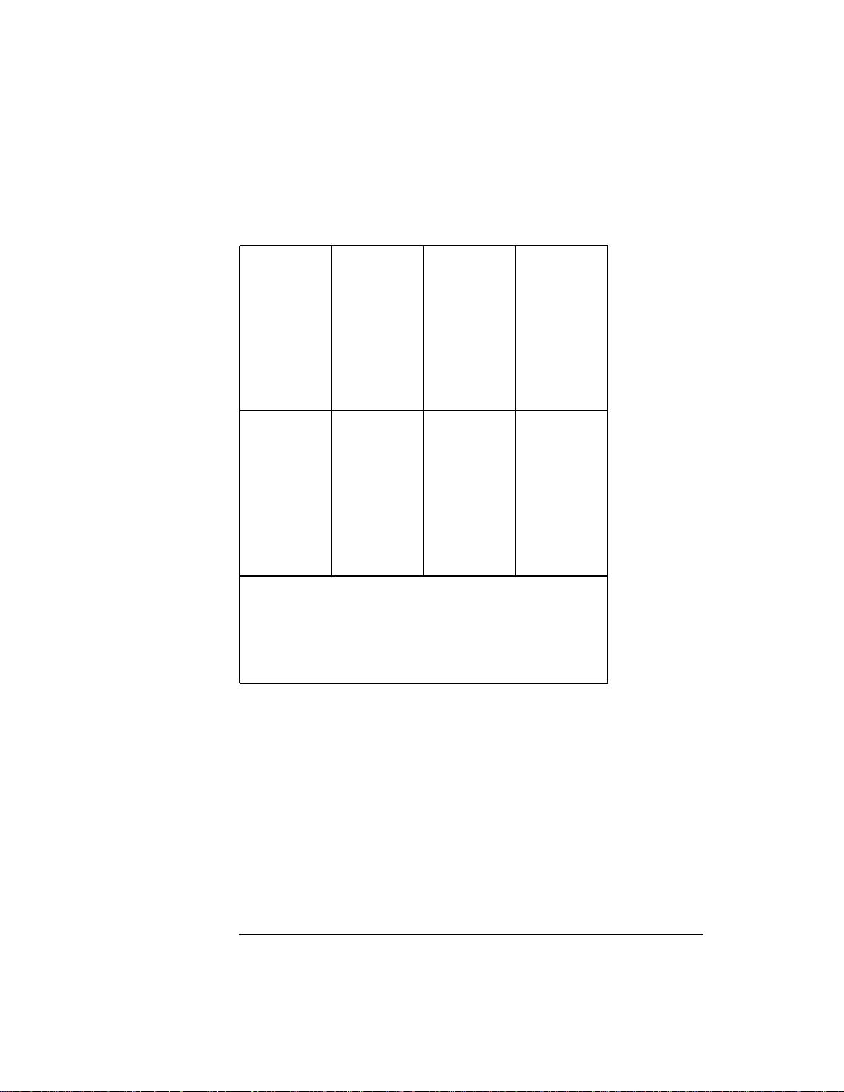
The following listing contains several assembly language statements.
The headings identify the four fields.
Label Opcode Operands Comments
JAN .EQU 1 ;declares a symbolic constant
SUM .WORD 0 ;reserve a word and set to zero
LOOP LDW 4(%r1),%r2
ADD %r2,%r3,%r4
STW %r4,SUM-$global$(%dp)
BL LOOP,%r0
Statements are normally written on separate lines. It is sometimes
useful, especially when using a macro preprocessor, to be able to write
several statements on one line. This can be done by separating the
statements with the “!” character. When this feature is used, a label can
be placed only on the first statement of the line, and a comment can only
follow the last statement on the line. The .LABEL directive can override
this condition by providing a means for declaring a label within a
multi-statement line.
20 Chapter 2
Page 21

Program Structure
Symbols and Constants
Symbols and Constants
Both addresses and constants can be represented symbolically. Labels
represent a symbolic address except when the label is on an .EQU, .REG,
or .MACRO directive. If the label is on an .EQU or .REG directive, the
label represents a symbolic constant. If the label is the .MACRO directive,
the label represents a macro name.
Symbols are composed of uppercase and lowercase letters (A-Z and a-z),
decimal digits (0-9), dollar signs ($), periods (.), ampersands (&), pound
signs (#), and underscores (_). A symbol can begin with a letter, digit,
underscore, or dollar sign. If a symbol begins with a digit it must contain
a non-digit character. (The predefined register symbols begin with a
percent sign (%).)
The Assembler considers uppercase and lowercase letters in symbols to
be distinct. The mnemonics for operation codes, directives, and
pseudo-operations can be written in either case. There is no explicit limit
on the length of a symbol. The following are examples of legal symbols:
$START$ _start PROGRAM M$3 $global$
$$mulI main P_WRITE loop1 1st_time
The following are examples of illegal symbols:
LOOP|1 Contains an illegal character
&st_time Begins with &
123 Does not contain a nondigit
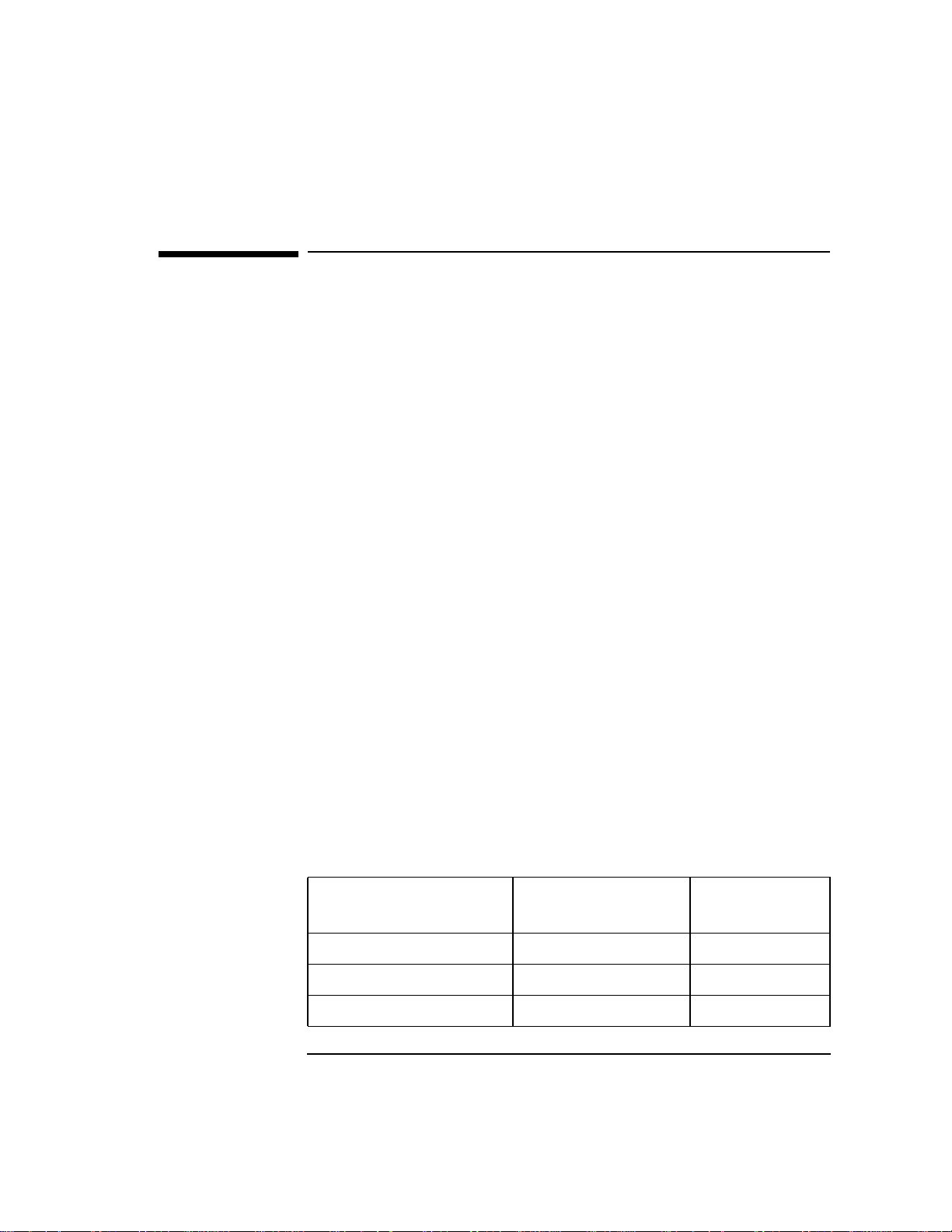
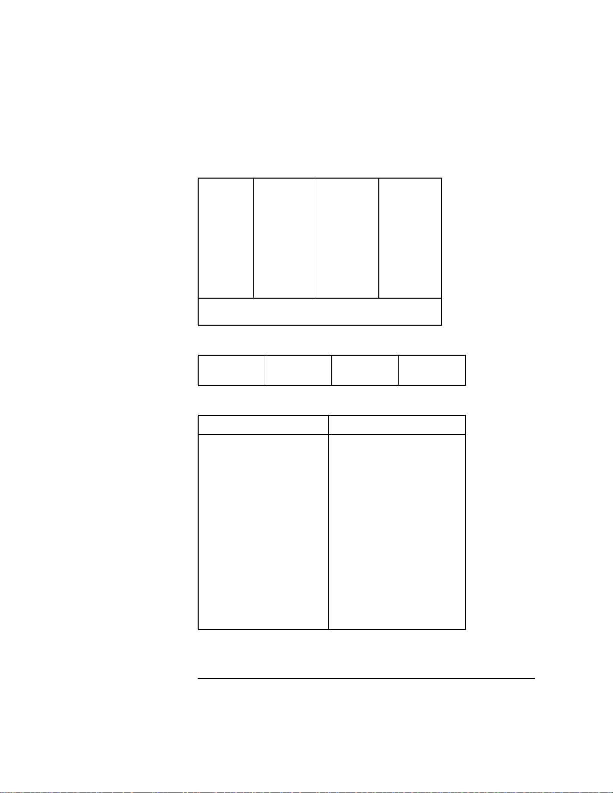
Integer constants can be written in decimal, octal, or hexadecimal
notation, as in the C language. “Integer Constants” on page 22 lists the
ranges of these integer constants.
Chapter 2 21
Page 22
Program Structure
Symbols and Constants
Table 2-1 Integer Constants
Signed Unsigned
Decimal -2147483648
through
2147483647
Octal 020000000000
through
017777777777
Hexadecimal 0x80000000
through
0x7FFFFFFF
The period (.) is a special symbol reserved to denote the current offset of
the location counter. It is useful in address expressions to refer to a
location relative to the current instruction or data word. This symbol is
considered relocatable, and can be used anywhere a relocatable symbol
can be used, with the exception of the label field.
The period cannot be used in an expression involving another label, such
as sym+., sym-., .+sym, or .-sym. It can be used in an expression that
has only a constant, such as .+8 or .-8.
0
through
4294967295
0
through
037777777777
0
through
0xFFFFFFFF
22 Chapter 2
Page 23

Program Structure
Registers and Register Mnemonics
Registers and Register Mnemonics
PA-RISC processors have four sets of registers:
• General
• Floating-point
• Space
• Control
Data is loaded from memory into general or floating-point registers and
stored into memory from general or floating-point registers. Arithmetic
and logical operations are performed on the contents of the general
registers. On P A-RISC 1.0 or 1.1 each general register is 32 bits wide . On
PA-RISC 2.0 each general register is 64 bits wide. On PA-RISC 2.0W
(true 64-bit environment) each general register is 64 bits wide.
There are 32 general registers, denoted as %r0 through %r31. General
register %r0 is special because “writes” into it are ignored, and it always
reads as zero. The remaining general registers can be used normally,
with the caution that %r1 is the implicit target register for the ADDIL
instruction, %r31 is the implicit link register for theBLE instruction, and
for PA-RISC 2.0 only, %r2 is the implicit link register for the BLVE
instruction. Certain general registers also have predefined conventional
uses. Refer to “Register Procedure Calling Conventions” on page 28. You
can find detailed information on both 32-bit and 64-bit runtime
architecture under the topic PA-RISC Architecture at
http://www.software.hp.com/STK/.
PA-RISC 1.0 machines ha ve 16 floating-point registers; P A-RISC 1.1, 2.0,
and 2.0W (true 64-bit environment) machines have 32 floating-point
registers. Each register is capable of holding either a single- or
double-precision floating-point number in IEEE format. These registers
are denoted %fr0 through %fr15 for PA-RISC 1.0 and %fr0 through
%fr31 for PA-RISC 1.1, 2.0, and 2.0W.
Registers %fr1, %fr2, and %fr3 are exception registers and are not
available to the programmer. Floating-point register %fr0 contains a
permanent floating-point zero when used in an arithmetic operation;
when written or read with floating-point loads or stores, the
floating-point status register is actually accessed.
Chapter 2 23
Page 24

Program Structure
Registers and Register Mnemonics
In addition, on PA-RISC 1.1, 2.0. and 2.0W the left and right halves of
the floating-point registers can be accessed as separate single-precision
registers by using an L or R suffix.
For example, %fr8R accesses the right-most 32 bits of %fr8 as a
single-precision number.
The L or R suffixes can only be used on the predefined floating-point
registers in the form %frnn, where nn is the register number. It is not
legal to use L or R with an integer value. For example, %fr8R is legal; 8R
is not legal.
The space registers form the basis of the virtual memory system. Each of
the eight space registers can hold a 16- or 32-bit space identifier,
depending on the hardware model. The space registers are denoted as
%sr0 through %sr7. Space register %sr0 is set implicitly by the BLE
instruction, and space registers %sr5 through %sr7 cannot be modified
except by code running at the most privileged level.
The control registers contain system-state information. There are 25
control registers, denoted as %cr0 and %cr8 through %cr31. Of these
registers, only %cr11 (%sar), the shift amount register, and %cr16
(%itmt), the interval timer, are normally accessible to the user-level
programmer. The other registers are accessed only by code running at
the most privileged level.
Register operands are denoted by register-typed constants because the
Assembler needs to be able to differentiate between general registers,
space registers, floating point registers, and ordinary integer constants.
To make assembly code more readable , you can use the.REG directive to
declare a symbolic name as an alias for a predefined register. The
predefined registers have a register type associated with them. The
Assembler enforces register type checking and issues a warning message
if the wrong kind of register is used within an operand. A warning is also
issued when an integer constant or absolute expression is found where a
register is expected. You must use the .REG directive to define symbolic
register names. If a symbolic name defined in an .EQU directive is used
where a register symbol is expected, the Assembler issues a warning
message, because it considers an .EQU defined symbol to be a simple
integer constant.
NOTE If an absolute expression is used instead of a register or register-typed
symbol name, the Assembler issues warning message number 41.
24 Chapter 2
Page 25
This warning can be suppressed with the -w41 command-line option.
Future versions of the Assembler may not always allow an absolute
expression where a register is expected.
The following example demonstrates the correct usage of the .REG
directive:
tblptr .REG %r20
aka_tbl .REG tblptr
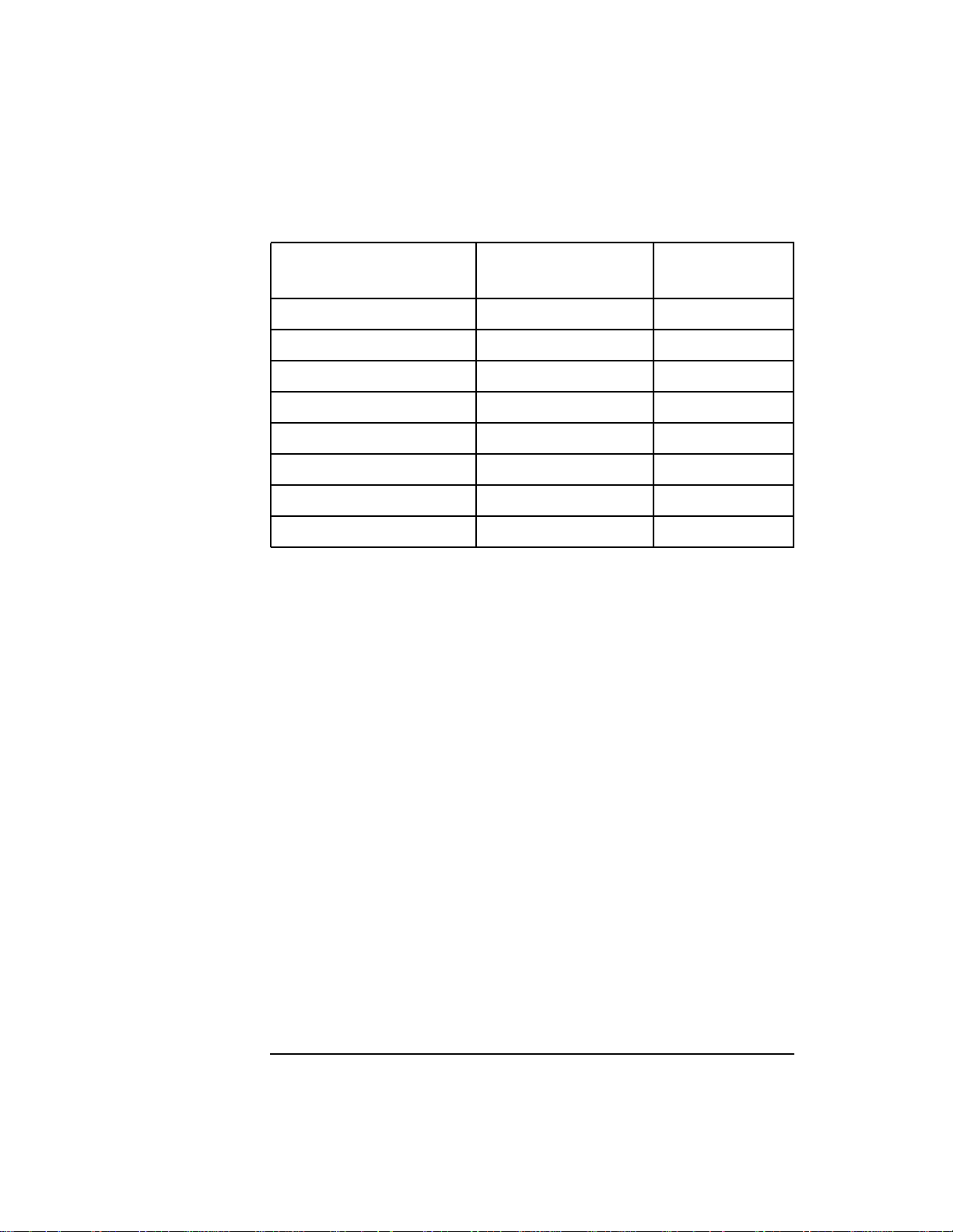
Predefined registers are shown in the following tables. All of the
mnemonics begin with the % character, so they do not conflict with any
programmer-defined symbols.
Table 2-2 General Registers
%r0 %r8 %r16 %r24
%r1 %r9 %r17 %r25
%r2 %r10 %r18 %r26
%r3 %r11 %r19 %r27
%r4 %r12 %r20 %r28
%r5 %r13 %r21 %r29
%r6 %r14 %r22 %r30
%r7 %r15 %r23 %r31
Program Structure
Registers and Register Mnemonics
Chapter 2 25
Page 26
Program Structure
Registers and Register Mnemonics
Table 2-3 Single-Precision Floating-Point Registers
%fr0L %fr8L %fr16L %fr24L
%fr1L %fr9L %fr17L %fr25L
%fr2L %fr10L %fr18L %fr26L
%fr3L %fr11L %fr19L %fr27L
%fr4L %fr12L %fr20L %fr28L
%fr5L %fr13L %fr21L %fr29L
%fr6L %fr14L %fr22L %fr30L
%fr7L %fr15L %fr23L %fr31L
%fr0R %fr8R %fr16R %fr24R
%fr1R %fr9R %fr17R %fr25R
%fr2R %fr10R %fr18R %fr26R
%fr3R %fr11R %fr19R %fr27R
%fr4R %fr12R %fr20R %fr28R
%fr5R %fr13R %fr21R %fr29R
%fr6R %fr14R %fr22R %fr30R
%fr7R %fr15R %fr23R %fr31R
Accessing the right half of floating-point registers
separately is possible only on PA-RISC 1.1 or later
architectures.
Registers %fr16L through %fr31L and %fr16R
through %fr31R are available only on PA-RISC 1.1 or
later architectures.
26 Chapter 2
Page 27
Registers and Register Mnemonics
Table 2-4 Double-Precision Floating-Point Registers
%fr0 %fr8 %fr16 %fr24
%fr1 %fr9 %fr17 %fr25
%fr2 %fr10 %fr18 %fr26
%fr3 %fr11 %fr19 %fr27
%fr4 %fr12 %fr20 %fr28
%fr5 %fr13 %fr21 %fr29
%fr6 %fr14 %fr22 %fr30
%fr7 %fr15 %fr23 %fr31
Registers %fr16 through %fr31 are available
only on PA-RISC 1.1 or later architectures.
Table 2-5 Space Registers
%sr0 %sr2 %sr4 %sr6
%sr1 %sr3 %sr5 %sr7
Table 2-6 Control Registers
Program Structure
Registers Synonyms Registers Synonyms
%cr0 %rctr %cr20 %isr
%cr8 %pidr1 %cr21 %ior
%cr9 %pidr2 %cr22 %ipsw
%cr10 %ccr %cr23 %eirr
%cr11 %sar %cr24 %tr0 %ppda
%cr12 %pidr3 %cr25 %tr1 %hta
%cr13 %pidr4 %cr26 %tr2
%cr14 %iva %cr27 %tr3
%cr15 %eiem %cr28 %tr4
%cr16 %itmr %cr29 %tr5
%cr17 %pcsq %cr30 %tr6
%cr18 %pcoq %cr31 %tr7
%cr19 %iir
Chapter 2 27
Page 28
Program Structure
Registers and Register Mnemonics
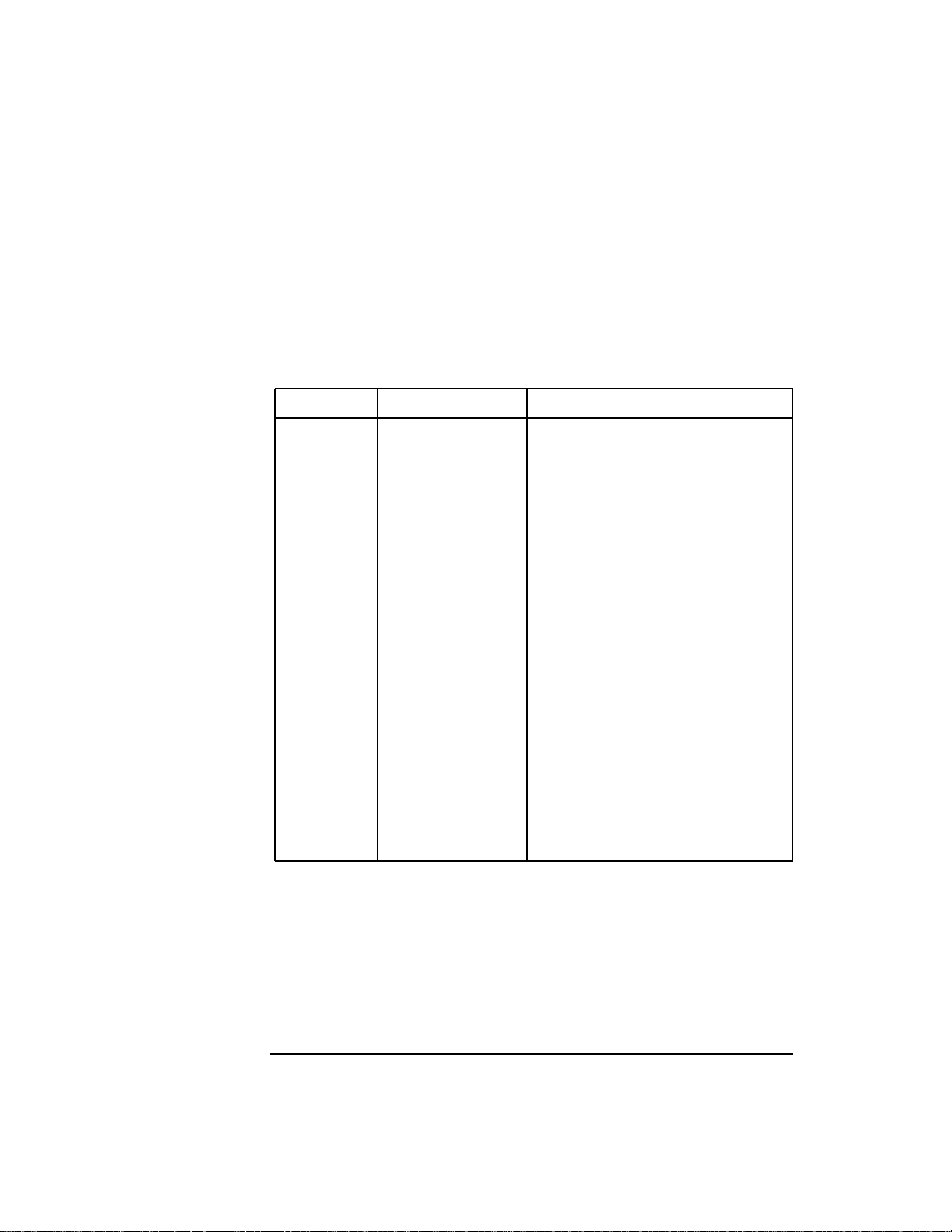
Some additional predefined register mnemonics are provided in
“Register Procedure Calling Conventions” on page 28 to match the
standard procedure-calling convention. This is discussed briefly in
“HP-UX Architecture Conventions” on page 39. You can find detailed
information on both 32-bit and 64-bit calling conventions under the topic
PA-RISC Architecture at URL: http://www.software.hp.com/STK/.
Table 2-7 Register Procedure Calling Conventions
Register Synonyms Description
%fr4 %farg0 %fret Floating argument, return value
%fr5 %farg1 Second floating argument
%fr6 %farg2 Third floating argument
%fr7 %farg3 Fourth floating argument
%r2 %rp Return link
%r19 %t4 Fourth temporary register
%r20 %t3 Third temporary register
%r21 %t2 Second temporary register
%r22 %t1 First temporary register
%r23 %arg3 Argument word 3
%r24 %arg2 Argument word 2
%r25 %arg1 Argument word 1
%r26 %arg0 Argument word 0
%r27 %dp Data pointer
%r28 %ret0 Return value
%r29 %ret1 %sl Return value, static link
%r30 %sp Stack pointer
%r31 %mrp Millicode return link
%sr1 %sret %sarg Return value, argument
In addition, there is a special register mnemonic defined as
%previous_sp, that allows access to the previous value of the stack
pointer.
%previous_sp must be used in the position of a base register; it can be
used only between .ENTER and .LEAVE pseudo-operations.
%previous_sp is the same as %sp unless the current .PROC has a large
28 Chapter 2
Page 29
frame (that is, .CALLINFO specified FRAME > 8191) or .CALLINFO
specified .ALLOCA_FRAME. In those two cases, %previous_sp is the
same as %r3, and %r3 is set up by the .ENTER pseudo-operation.
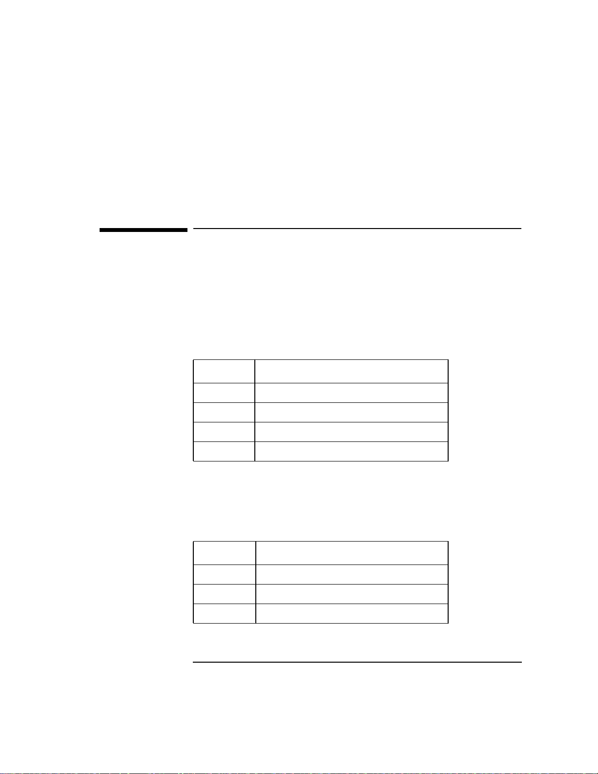
Expressions
Arithmetic expressions are often valuable in writing assembly code. The
Assembler allows expressions involving integer constants, symbolic
constants, and symbolic addresses. These terms can be combined with
the standard arithmetic operators shown in “Standard Arithmetic
Operators” on page 29 or with bit-wise operators shown in “Bit-Wise
Operators” on page 29.
Table 2-8 Standard Arithmetic Operators
Operator Operation
+ Integer addition
Program Structure
Expressions
- Integer subtraction
* Integer multiplication
/ Integer division (result is truncated)
The multiplication and division operators have precedence over addition
and subtraction. That is, multiplications and divisions are performed
first from left to right, then additions and subtractions are performed
from left to right. Therefore, the expression 2+3*4 evaluates to 14.
Table 2-9 Bit-Wise Operators
Operator Operation
| Logical OR
& Logical AND
~ Unary logical complement (tilde)
Chapter 2 29
Page 30
Program Structure
Expressions
Expressions produce either an absolute or a relocatable result. Any
operation involving only absolute terms yields an absolute result.
Relocatable terms are allowed only for the + and - operators. The legal
combinations involving relocatable terms are shown in “Legal
Combinations For Relocatable Terms” on page 30.
Table 2-10 Legal Combinations For Relocatable Terms
Operation Result
Absolute + Relocatable Relocatable
Relocatable + Absolute Relocatable
Relocatable - Absolute Relocatable
Relocatable - Relocatable (defined locally) Absolute
For more information on the term relocatable, refer to “Assembler
Features” on page 15.
NOTE The combination “relocatable-relocatable+relocatable” is not permitted.
For example, assume the symbols MONTH and YEAR are relocatable, and
JANUARY and FEBRUARY are absolute. The expressions MONTH+JANUARY
and MONTH+FEBRUARY-4 are relocatable, while the expressions
YEAR-MONTH and FEBRUARY-4 are absolute. The expression
MONTH+JANUARY*4 is also legal and produces a relocatable result,
because JANUARY*4 is evaluated first, producing an absolute
intermediate result that is added to MONTH. The expression MONTH+YEAR
is illegal, because the sum of two relocatable terms is not permitted.
Because all instructions are a single word in length, it is not possible to
form a complete 32-bit address in a single instruction. Therefore, it is
likely that the Assembler (or linker) may not be able to insert the final
address of a symbol into the instruction as desired. For example, to load
the contents of a word into a register, the following instruction could be
used:
LDW START,%r2
Because LDW provides only 14 bits for the address of START, the
Assembler or linker prints an error message if the address of START
requires more than 14 bits. There are two instructions,LDIL and ADDIL,
whose function is to form the left-most 21 bits of a 32-bit address. The
succeeding instruction, by using the target of the LDIL or ADDIL as a
30 Chapter 2
Page 31

base register, needs only 11 bits for the remainder of the address. The
Assembler provides special operators, called field selectors, that extract
the appropriate bits from the result of an expression. With the field
selectors L' and R', the previous example can be recoded as follows:
LDIL L'START,%r1 ;put left part into r1
LDW R'START(%r1),%r2 ;add r1 and right part
The field selectors are always applied to the final result of the
expression. They cannot be used in the interior of an expression.
“Available Field Selectors” on page 31 shows all the available field
selectors and their meanings.
Table 2-11 Available Field Selectors
Program Structure
Expressions
Field
Selector
Meaning
F' or F% Full 32 bits (default).
L' or L% Right-justified, high-order 21 bits.
R' or R% Low-order 11 bits.
LS' or
LS%
RS' or
High-order 21 bits after rounding to nearest multiple of
2048.
Low-order 11 bits, sign extended.
RS%
LD' or
LD%
RD' or
Right-justified, high-order 21 bits after rounding to next
multiple of 2048.
Low-order 11 bits, with negative sign.
RD%
LR' or
LR%
RR' or
RR%
L% value with constant rounded to nearest multiple of
8192.
R% value with constant rounded to nearest multiple of
8192, plus the difference of the constant and the rounded
constant.
T' or T% F% value offset of data linkage table slots from linkage
table pointer. In 32-bit mode, the linkage table pointer is
%r19. In 64-bit mode, the linkage table pointer is %r27.
Chapter 2 31
Page 32

Program Structure
Expressions
Field
Selector
LT' or
LT%
RT' or
RT%
Q' or Q% F% value offset of procedure linkage table slots from
LRQ' or
LRQ%
RRQ' or
RRQ%
P' or P% Data procedure label (plabel) constructor.
LR% value offset of data linkage table slots from linkage
table pointer. In 32-bit mode, the linkage table pointer is
%r19. In 64-bit mode, the linkage table pointer is %r27.
RR% value offset of data linkage table slots from linkage
table pointer. In 32-bit mode, the linkage table pointer is
%r19. In 64-bit mode, the linkage table pointer is %r27.
linkage table pointer. In 32-bit mode, the linkage table
pointer is %r19. In 64-bit mode, the linkage table pointer
is %r27.
LR% value offset of procedure linkage table slots from
linkage table pointer. In 32-bit mode, the linkage table
pointer is %r19. In 64-bit mode, the linkage table pointer
is %r27.
RR% value offset of procedure linkage table slots from
linkage table pointer. In 32-bit mode, the linkage table
pointer is %r19. In 64-bit mode, the linkage table pointer
is %r27.
Meaning
LP' or
LP%
RP' or
RP%
N' or N% A null field selector , whic h is applied to an LDO instruction
NL' or
NL%
32 Chapter 2
Code procedure label (plabel) constructor used in LDIL
instruction.
Code procedure label (plabel) constructor used in LD0
instruction.
to allow a three-instruction sequence.
Right-justified, high-order 21 bits; allows a
three-instruction sequence.
Page 33

Program Structure
Expressions
Field
Selector
NLD' or
NLD%
NLR' or
NLR%
NLS' or
NLS%
Right-justified, high-order 21 bits after rounding to next
multiple of 2048; allows a three-instruction sequence.
L% value with constant rounded to nearest multiple of
8192; allows a three-instruction sequence.
High-order 21 bits after rounding to nearest multiple of
2048; allows a three-instruction sequence.
Meaning
On PA-RISC 1.0, the page size is 2048 bytes long; on PA-RISC 1.1, 2.0,
and 2.0W the page size is 4096. The selectors L', LS', and LD' modulate
by 2048, and the corresponding selectors R', RS', and RD' extract the
offset relative to that address.
The distinction is whether the offset is always positive and between 0
and 0x7ff (L'-R'), always negative and between -0x800 and -1
(LD'-RD'), or between -0x400 and 0x3ff (LS'-RS'). This
distinction is only important when using short addressing near a
quadrant boundary, because only the left part is used to select a space
register. Each pair is designed to work together just as L' and R' do in
the previous example. See “Spaces” on page 39. The LR' and RR'
prefixes are used for accessing different fields of a structure, allowing the
sharing of the LR' computation.
For shared libraries , the field selectorsT', LT', RT', Q', LRQ', and RRQ'
are used in conjunction with the position-independent code options +z or
+Z.
The field selectors P', LP', and RP' are used to form plabels
(procedure labels) for use in dynamic calls. With position-independent
code, the use of plabel values, rather than simple code addresses, is
required. Refer to the HP-UX Linker and Libraries Online User Guide
and ELF 64 Object File Format, http://www.software.hp.com/STK/ for
more information.
For example, to get a procedure label for foo, use the following code:
ADDIL LTP'foo,%r27,%r1 ;get left portion of plabel pointer.
LDO RTP'foo(%r1),%r4 ;add right portion to form a complete
; plabel pointer.
The field selectors in the above example can also be written LP% and RP%.
Chapter 2 33
Page 34

Program Structure
Expressions
Parenthesized Subexpressions
The constant term of an expression may contain parenthesized
subexpressions that alter the order of evaluation from the precedence
normally associated with arithmetic operators. For example:
LABEL1-LABEL2+((6765+(2048-1))/2048)*2048
contains a parenthesized subexpression that rounds a value up to a
multiple of 2048.
Absolute symbols may be equated to constant terms containing
parenthesized subexpressions as in the following sequence:
BASE .EQU 0x200
N_EL .EQU 24
SIZE .EQU (BASE+4)*N_EL
NOTE The use of parentheses to group subexpressions may cause ambiguities
in statements where parenthesized register designators are also
expected.
34 Chapter 2
Page 35

Program Structure
Operands and Completers
Operands and Completers
Machine instructions usually require one or more operands.
These operands tell the processor what data to use and where to store
the result. Operands can identify a register, a location in memory, or an
immediate constant (that is, data that is coded into the instruction
itself). The operation code determines how many and what kinds of
operands are required.
Registers used in operands should be either predefined register symbols
(with the % prefix) or user -defined register symbols defined with the.REG
directive. They can also be absolute expressions. See “Registers and
Register Mnemonics” on page 23 in this chapter.
The following example shows a few machine instructions with register
operands:
SCRATCH .REG %r18 ;define register SCRATCH
ADD %r3,%r7,%r4 ;r3 + r7 -> r4
OR %r7,%r3,%r8 ;inclusive or of r7,r3 -> r8
COPY SCRATCH,%r7 ;copy r18 to r7
MTCTL %r2,%sar ;set shift amount register (cr11)
MFSP %sr4,%r10 ;fetch contents of sr4
Operands designating memory locations usually consist of an expression
and a general register used as a base register. Some instructions also
require a space register designation. In general, such operands are
written in the form expr(sr,gr) or expr(gr), as in the following
examples:
local_off .EQU -64
LDW 4(%dp),%r2
STW %r0,local_off-4(%sp)
LDW 0(%sr3,%r2),%r9
Notice that the space register can be omitted on instructions that allow
short addressing, as in the STW instruction shown above.
If only one register is given, it is assumed to be the general register, and
the space register field in the machine instruction is set to zero, which
indicates short addressing.
The expression in a memory operand is either absolute or relocatable.
Absolute expressions are meaningful when the base register contains the
address of an array, record, or the stack pointer to which a constant offset
Chapter 2 35
Page 36

Program Structure
Operands and Completers
is required. Relocatable expressions are meaningful when the base
register is %r0, or when the base register contains the left part of a 32-bit
address as illustrated in the following example:
LDIL L%glob,%r1 ;set up %r1 for STW
STW %r9,R%glob(%r1)
Immediate operands provide data for the machine language instruction
directly from the bits of the instruction word itself. A few instructions
that use immediate operands are shown below:
ADDIL L%var,%dp
LDIL L%print,%r1
ADDI 4,%r3,%r5
SUBI 0x1C0,%r14,%ret0
Completers are special flags that modify an instruction's behavior. They
are written in the opcode field, separated from the instruction mnemonic
by a comma. The most common type of completer is a condition test.
Many instructions can conditionally trap or nullify the following
instruction, depending on the result of their normal operation. For
example, notice the completers in the sequence below:
ADD,NSV %r1,%r2,%r3
BL,N handle_oflo,%r0
OR %r3,%r4,%r5
The ,NSV in the ADD instruction nullifies the BL instruction if no
overflow occurs in the addition operation, and execution proceeds with
the OR instruction. If overflow does occur, the BL instruction is executed,
but the ,N completer on the BL specifies that the OR instruction in its
delay slot should not be executed.
Each class of machine instructions defines the set of completers that can
be used.
These are described in the PA-RISC 1.1 Architecture and Instruction Set
Reference Manual and in PA-RISC 2.0 Architecture.
36 Chapter 2
Page 37

Program Structure
Macro Processing
Macro Processing
A macro is a user-defined word that is replaced by a sequence of
instructions. Including a macro in a source program causes the sequence
of instructions to be inserted into the program wherever the macro
appears.
A user may define a word as a macro by using the .MACRO directive.
Detailed information about macro arguments, placement and
redefinition of macros, nested macro definitions, and nested macro calls
is in “Assembler Directives and Pseudo-Operations” on page 53.
Defining New Instructions With Macros
If you are testing new CPUs or coprocessors, you may need to use
opcodes that are unknown to the Assembler. A variant of a macro
definition may be used to create a mnemonic for the instruction. After
being defined, the new mnemonic instruction can be invoked as easily as
a standard instruction.
Opcodes, subopcodes, completers, and operands are encoded into the
instruction word in a bit-intensive manner because all PA-RISC
instructions are one word, or 32-bits, in length.
To write a macro, you must specify explicitly which bit fields are to
contain constants and which are to contain macro arguments. The macro
processor has no built-in knowledge of instruction formats. Defining new
instructions through macros is only possible because a convenient way to
delimit bit fields has been provided. It is up to the programmer to choose
the correct bit field.
Bit positions within the 32-bit word are numbered from zero to 31, from
left to right. A bit range is indicated by the starting bit position followed
by the ending bit position. The two bit positions are separated by two
periods and enclosed in braces. The bit field beginning at bit position 6
and ending at bit position 10 is represented as:
{6..10}
If the bit field being assigned from is bigger than the bit field being
assigned to, then a warning is issued and the assigned-from bit field is
truncated on the left. When no bit field is specified for the assigned-from
Chapter 2 37
Page 38

Program Structure
Macro Processing
value, low-order bits are used until the value of the assigned-from bit
field becomes the same as the width of the assigned-to bit field. The
assigned-to bit field must always be specified.
No sign extension is provided by the macro assembler when bit fields are
generated.
The following macro definition defines the macro PACK with four formal
parameters.
PACK .MACRO BASE,GREG,SREG,OFFSET
{0..5}=0x3E{26..31}
{6..10}=BASE{27..31}
{11..15}=GREG{27..31}
{16..17}=SREG{30..31}
{18..31}=OFFSET{18..31}
.ENDM
The following explanation assumes that PACK is invoked with the
statement:
PACK %sp,%r19,%sr0,-52
Bit Field Description
{0..5} Contains the six low-order bits of the new opcode 0x3E,
or binary 111110, entered as a constant in the macro
definition.
{6..10} Contains general register 30, or binary 11110. These
are the five low-order bits of the argument BASE in the
macro definition.
{11..15} Contains general register 19, or binary 10011. These
are the five low-order bits of the argument GREG in the
macro definition.
{16..17} Contains space register 0 and represents the five
low-order bits of the argument SREG in the macro
definition.
{18..31} Contains binary 11111111001100, the OFFSET value
−52, which was entered as an argument to the macro
definition.
38 Chapter 2
Page 39

3 HP-UX Architecture
Conventions
The Assembler is a flexible tool for writing programs, but every operating
system imposes certain conventions and restrictions on the programs
that are intended to run on that system. This chapter discusses the
conventions that must be understood in order to write assembly
language programs and procedures for the PA-RISC instruction set on
the HP 9000 Series 700 and 800 HP-UX operating system. Several
Assembler directives are mentioned in this chapter to place them in a
meaningful context. A full discussion of these directives is in Chapter 4,
“Assembler Directives and Pseudo-Operations,” on page 53.
Spaces
Virtual addressing on PA-RISC is based on spaces. A virtual address is
composed of a space identifier, which is either 16 or 32 bits long
(depending on the hardware model), and a 32-bit offset within the space.
Therefore, each space can contain up to 4 gigabytes, and there is a large
supply of spaces.
NOTE In the 64-bit mode architecture each application is provided a flat virtual
address space of 2** 64 bytes, which is divided into four quadrants. Each
quadrant is mapped into this global virtual address space by means of
four space registers, which are under the control of the operating
system.
Every program on an HP-UX system is assigned two spaces when it is
loaded for execution by the operating system: one for code, and one for
data. The HP-UX operating system makes the code space read only, so
that it can be shared whenever several processes are executing the same
program. The data space is writable by the new process, and is private to
that process; that is, every process has a unique data space.The actual
space identifiers assigned to these two spaces can vary from one
execution of the program to the next; these numbers cannot be
determined at compile time or link time. Generally, programmers do not
need to be concerned with the space identifiers, since the operating
system places them in two reserved space registers, where they remain
39
Page 40

HP-UX Architecture Conventions
Spaces
for the duration of program execution. The identifier of the code space is
placed in space register 4 (%sr4) and the identifier of the data space is
placed in space register 5 (%sr5).
When writing an assembly language program, declare a space named
$TEXT$ for executable code, and a space named $PRIVATE$ for
modifiable data. Constant data or literals that you do not plan to modify
during program execution, can be placed in either space. Placing
constant data in the $TEXT$ space decreases the size of the nonsharable
part of your program and improves the overall efficiency of the operating
system.
The particular space registers mentioned above play an important role in
virtual addressing. While many of the branching instructions, such as
BL, BLR, and BV, are capable of branching only within the currently
executing code space (called PC-space), two of the branching instructions,
BE and BLE, require that you specify a space register as well as an offset.
These instructions allow you to branch to code executing in a different
space. On HP-UX systems, normally all code for a program is contained
in one space, so all BE and BLE instructions should be coded to use %sr4.
In contrast, the memory reference instructions, such as LDW and STW,
allow a choice between two forms of addressing: long and short. With
long addressing, you can choose any of the space registers 1 through 3 for
the space identifier part of the virtual address. The space offset is formed
as the sum of an immediate displacement and the contents of a general
register. With short addressing, one of the space registers between 4
through 7 is chosen automatically, based on the high-order two bits of the
base register. Each space addressed by these four space registers is
effectively divided into four quadrants, with a different quadrant of each
space accessible via short addressing.
On HP-UX systems, all of a program's code is placed in quadrant zero of
the $TEXT$ space, or %sr4, (space offsets from 0 through 0x3FFFFFFF).
The data is placed in quadrant one of the $PRIVATE$ space, or %sr5
(space offsets from 0x40000000 through 0x7FFFFFFF). Therefore,
literal data in the code space and modifiable data in the data space can
be addressed using the short addressing technique, without any concern
for the space registers.
The identifier for shared memory segments, including shared library
text, is placed into space register 6 (%sr6). Shared memory and shared
library text are placed into quadrant two of the shared memory space
(offsets 0x80000000 through 0xBFFFFFFF). The identifier for system
40 Chapter 3
Page 41

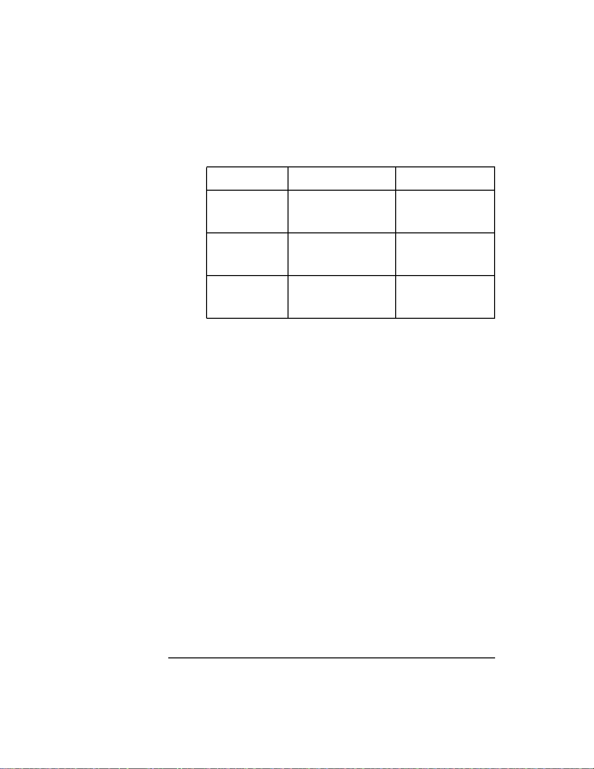
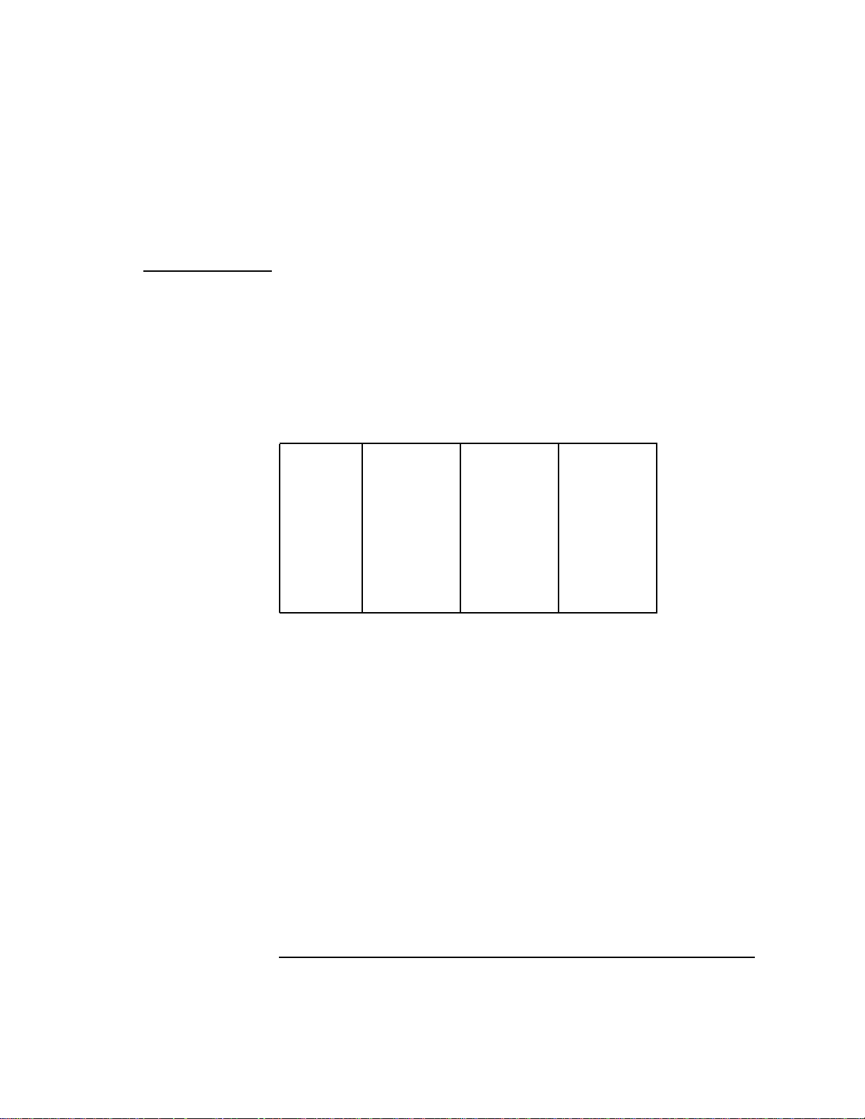
code is placed into space register 7 (%sr7). System code is placed into
quadrant three of the system space (offsets 0xC0000000 through
0xFFFFFFFF). Table 3-1 on page 41 shows the memory layout on HP-UX.
Table 3-1 Memory Layout on HP-UX
%sr4 %sr5 %sr6 %sr7
0x00000000 Program
code
0x40000000 Program
data stack
Shared
library data
0x80000000 Shared
0xC0000000 System code
HP-UX Architecture Conventions
Spaces
memory
Shared
library text
You can define spaces other than $TEXT$ and $PRIVATE$ in a program
file by declaring a special kind of space called an unloadable space.
Unloadable spaces are treated as normal spaces by the linker, but as the
name implies, are not actually loaded when a program is executed.
Unloadable spaces are typically used by compilers to store extra
information within a program file. The most common example of an
unloadable space is $DEBUG$, which is used to hold symbolic debugging
information.
The sort key attribute allows the programmer to control the placement of
a space relative to the other spaces. The linker places spaces with lower
sort keys in front of spaces with higher sort keys.
The .SPACE directive is used to declare spaces. The assembly language
programmer is not required to fill one space before beginning another.
When a space is first declared, the Assembler begins filling that space.
The .SPACE directive can also be used to return to a previously declared
space, and the Assembler continues to fill it as if there had been no
intervening spaces.
Chapter 3 41
Page 42

HP-UX Architecture Conventions
Subspaces
Subspaces
While a space is a fundamental concept of the architecture, a subspace is
just a logical subdivision of a space. The Assembler places the program's
code and data into subspaces within spaces. Each subspace belongs to
the space that was current when the subspace was first declared. The
linker groups subspaces into spaces as it builds an executable program
file. For more details see the ld(1) entry in the HP-UX Reference. When
the linker combines several relocatable files, it groups the subspaces
from each file by name, so that all subspaces with the same name are
placed contiguously in the program.
Attributes
Subspaces have several attributes. The alignment attribute specifies
what memory alignment (in bytes) is required in the virtual address
space. The alignment can be any power of two, from 1 through 4096,
inclusive. Typically, the alignment is 4 or 8 to specify that the beginning
of the subspace must be word or double-word aligned. Normally, the
alignment attribute is computed automatically by the Assembler from
the largest .ALIGN directive used within the subspace.
The quadrant attribute assigns the subspace to one of the four quadrants
of its space. On HP-UX systems, all subspaces in the code space must be
in quadrant 0, and all subspaces in the data space must be in quadrant
1.
The access rights attribute specifies the access rights that should be
given to each physical page in the subspace. On HP-UX systems, all
subspaces in the code space must have access rights of 0x2C (code page
executable at any privilege level). All subspaces in the data space must
have access rights of 0x1F (data page readable and writable at all
privilege levels).
The sort key attribute allows the programmer to control the placement of
a subspace relative to the other subspaces in its space. The linker places
subspaces with lower sort keys in front of subspaces with higher sort
keys.
42 Chapter 3
Page 43

HP-UX Architecture Conventions
Subspaces
Directives
The .SUBSPA directive is used to declare a subspace and its attributes.
As with spaces, the assembly language programmer can switch from one
subspace to another, and the Assembler will fill each subspace
independently as if the source code had been presented one complete
subspace at a time. When the .SPACE directive is used to switch spaces,
the Assembler remembers the current subspace in each space.
Several additional Assembler directives are provided as shorthand to
declare and switch to some standard spaces and subspaces. For example,
the .CODE directive switches to the $TEXT$ space and the $CODE$
subspace, and the .DATA directive switches to the $PRIVATE$ space and
the $DATA$ subspace.
You can declare as many subspaces as you can use, but the sort key
attribute should be used carefully, because the stack unwind mechanism
reserves a range of sort keys 56 through 255 for the $TEXT$ space. Refer
to “Compiler Conventions” on page 47 in this chapter. Some of the
standard subspaces and sort keys used by the compilers are shown in
Table 3-2 on page 43. Directives that generate commonly used spaces
and subspaces are found in Table 4-3 on page 116.
Table 3-2 Standard Subspaces and Sort Keys
Space Subspace Sort Key Use
$TEXT$ 8
$CODE$ 24 Normal code.
$LIT$ 16 Literals.
$MILLICODE$ 8 Millicode library routines.
$SHLIB_INFO$ 0 Shared library information.
$UNWIND$ 64 Unwind information.
$PRIVATE$ 16
$BSS$ 82 Uninitialized data and common.
$DATA$ 16 Global arrays and structures.
$DLT$ 39 Data linkage table.
Chapter 3 43
Page 44

HP-UX Architecture Conventions
Sections in 64-bit Mode
Space Subspace Sort Key Use
$GLOBAL$ 40 Global variable base address.
$PLT 6 Procedure linkage table.
$SHLIB_DATA$ 12 Shared library data.
$SHORTBSS$ 80 Uninitialized data and common.
$SHORTDATA$ 24 Global scalar variables.
$THREAD_SPECIFIC$ 16
$TBSS$ 40 Thread local storage
Sections in 64-bit Mode
In 64-bit mode, the Executable and Linking F ormat (ELF) uses segments
and sections rather than spaces and subspaces.
The concept of spaces maps to the ELF concept of segments, but
segments do not apply to relocatable object files. Hence, the Assembler
ignores the .SPACE directive for 64-bit assembly programs. Subspaces
map directly to the ELF concept of sections, so the .SUBSPA directive
switches to or creates a new section. The attributes of a subspace
correspond to section attributes as follows:
• Subspace names listed in the table are mapped to their corresponding
section name. Names not in this table are unchanged.
SUBSPACE NAME SECTION NAME
$BSS$ .bss
$CODE$ .text
$DATA$ .data
$FINI$ .fini
44 Chapter 3
Page 45

HP-UX Architecture Conventions
Sections in 64-bit Mode
SUBSPACE NAME SECTION NAME
$INIT$ .init
$LIT$ .rodata
$MILLICODE$ .text
$PREINIT$ .preinit
$SHORTBSS$ .sbss
$SHORTDATA$ .sdata
$TBSS$ .tbss
• The assembler translates access rights into a set of read, write or
execute permissions for the section.
• The assembler ignores the sort key and quadrant attributes.
• The alignment attribute maps directly to the section alignment.
• The COMMON and DUP_COMM attributes map to a COMDAT section.
• The CODE_ONLY, FIRST, and FROZEN attributes are ignored.
• The UNLOADABLE attribute maps to a non-allocated section.
For more information about ELF, seeELF 64 Object File Format, at URL:
http://www .softw are.hp.com/STK/.
Chapter 3 45
Page 46

HP-UX Architecture Conventions
Location Counters
Location Counters
Just as spaces can be divided into subspaces, subspaces can be further
divided by using location counters. You can use up to four location
counters in each subspace, and the Assembler fills a separate area for
each location counter. When the assembly is complete, the subspace is
formed by concatenating each of these areas. All references relative to a
location counter are relocated so that they are relative to the complete
subspace.
Unlike subspaces, however, the use of location counters is completely
local to the Assembler. Once the subspace is formed at the end of the
assembly, the distinction among the individual areas built by location
counters disappears. No further reordering or grouping related to
location counters is performed by the linker.
This facility allows you to assemble related data into disjoint pieces of a
subspace, while keeping the source code in a convenient order.
The .LOCCT directive is used to switch from one location counter to
another. The Assembler automatically remembers the previous value of
each location counter within each subspace. When the.SUBSPA directive
is used to switch subspaces, the Assembler automatically begins using
the location counter that was last in effect in the new subspace.
46 Chapter 3
Page 47

HP-UX Architecture Conventions
Compiler Conventions
Compiler Conventions
In order to write assembly language procedures that can both call to and
be called from high-level language procedures, it is necessary to
understand the standard procedure-calling convention and other
compiler conventions.
On many computer systems, each high-level language has its own calling
convention. Consequently, calls from one language to another are
sometimes difficult to arrange, except through assembly code. The
architecture generally prescribes very few operations that must be done
to effect a procedure call, and there is often a pair of machine-language
instructions to call a procedure and return from one. PA-RISC
architecture provides no special procedure call or return instructions.
There is, however, a standard procedure-calling convention for all
high-level languages as well as the Assembler. It is tuned for the
architecture, and is designed to make a procedure call with as few
instructions as possible.
Besides defining a uniform call and return sequence for all languages,
the calling convention is important for other reasons. In order to
streamline the calling sequence, the return link is not saved on the stack
unless necessary and the previous stack pointer is rarely saved on the
stack. Therefore, it is not usually possible to obtain a stack trace at an
arbitrary point in the program without some additional static
information about each procedure's stack frame size and usage.
For example, you could not obtain a stack trace while debugging or
analyzing a core dump, or using the TRY/RECOVER feature in HP
Pascal/HP-UX. Obtaining a stack trace is made possible by the stack
unwind mechanism. It uses special unwind descriptors that contain the
exact static information needed for each procedure. These descriptors are
generated automatically by the linker based on information provided by
all high-level compilers as well as the Assembler.
Each descriptor contains the starting and ending address of a
procedure's object code, plus that procedure's stack frame size, and a few
flags indicating, among other things, whether the return link is saved on
the stack. Given the current program counter and stack pointer, the
stack unwind mechanism can determine the calling procedure by finding
Chapter 3 47
Page 48

HP-UX Architecture Conventions
Compiler Conventions
the return link either in a register or on the stack. Also, it can determine
the previous stack pointer by subtracting the current procedure's stack
frame size.
The Assembler requires that you follow programming conventions to
generate unwind descriptors. The beginning and end of each procedure
must be noted with the .PROC and.PROCEND directives. The .CALLINFO
directive supplies additional information about the procedure, including
the stack frame size. The Assembler passes this information to the
linker, which creates the unwind descriptor. It can also generate the
standard entry and exit code to create and destroy the stack frame, save
and restore the return link (if necessary), and save and restore any
necessary registers. These code sequences are generated at the points
indicated by the .ENTER and .LEAVE pseudo-operations. For a more
thorough discussion of programming conventions, refer to the 64-bit
Runtime Architecture for PA-RISC 2.0, at URL:
http://www.software.hp.com/STK/.
Arguments to procedures are loaded into general registers 26, 25, 24,
and 23; these registers are named, respectively, %arg0, %arg1, %arg2,
and %arg3. If more than four words of arguments are required, the
remaining arguments are stored in the caller's stack frame in the
variable argument list. The return value should be returned in general
register 28, called %ret0. General register 29, called %ret1, is used for
the low-order bits of a double-word return value, while %ret0 contains
the high order bits. In addition to the argument and return registers, the
procedure can use registers 19 through 22 and registers 1 and 31 as
scratch registers. Any other general registers must be saved before use
at entry and restored before exit.
Chapter 4, “Assembler Directives and Pseudo-Operations,” on page 53
contains detailed descriptions of the Assembler directives described
above. For a more thorough discussion of the procedure calling
conventions, refer to the topic PA-RISC Architecture at URL:
http://www.software.hp.com/STK/.
In order for an assembly language procedure to be callable from another
language or another assembly language module, the name of the
procedure must be exported. The .EXPORT directive does this. It also
allows you to declare the symbol type. For procedure entry points, the
symbol type should be ENTRY.
The Assembler and linker treat all symbols as case-sensitive, while some
compilers do not. By convention, compilers that are case-insensitive
uniformly convert all exported names to lower case. For example, it is
48 Chapter 3
Page 49

HP-UX Architecture Conventions
Compiler Conventions
possible to declare a procedure that cannot conflict with HP
Pascal/HP-UX procedure names by using uppercase letters. However,
there is an aliasing mechanism in some compilers that allows you to
declare a case-sensitive name for external use. See the appropriate
language reference manual for more information.
Conversely, the .IMPORT directive allows you to reference a procedure
name that is exported from another module, either from the Assembler
or the compiler. Once a procedure name has been imported, it can be
referenced exactly as if it were declared in the same module.
Data symbols can be exported and imported just like procedure names.
However, not all compilers export the names of global variables, or
provide a mechanism to reference data symbols exported from an
assembly language module. F or example, the HP P ascal/HP-UX compiler
does not normally do this, while the HP C/HP-UX compiler does. HP
FORTRAN 77/HP-UX named common blocks are exported, but the
names of the variables within the common blocks are not.
It was mentioned before that data is allocated beginning from a virtual
space offset 0x40000000. For convenience as well as compatibility with
future releases of HP-UX systems, all data in the$PRIVATE$ space must
be accessed relative to general register 27, called %dp. EStandard
run-time start-up code, from the file /usr/ccs/lib/crt0.o, must be
linked with every program. This start-up code declares a global symbol
called $global$ in the $GLOBAL$ subspace. This code also loads the
address of this symbol into the %dp register before beginning program
execution. This register must not be changed during the execution of a
program. Since the %dp register is known to contain the address of
$global$, the following single instruction does the load as long as the
displacement from $global$ to the desired location is less than 8
kilobytes:
LDW var-$global$(%dp),%r3
If the desired location is not known to be close enough to $global$, use
the following sequence:
Global Symbol Usage
ADDIL L'var-$global$,%dp ;result in r1
LDW R'var-$global$(%r1),%r3
Chapter 3 49
Page 50

HP-UX Architecture Conventions
Compiler Conventions
For convenience, the $SHORTDATA$ and $SHORTBSS$ subspaces can
be used for small scalar variables. Most scalar variables are close enough
to $GLOBAL$ so that the shorter form can be used. Arrays and large
structures should be defined in $DATA$ and the long form used.
To access items in the$PRIVATE$ space (global data), the following does
not work:
LDIL L'var,%r1 ;wrong
LDW R'var(%r1),%r3 ;wrong
This example assumes that the operating system always allocates data
at the same virtual space offset 0x40000000.
Thread local storage (TLS) data is accessed relative to control register 27
(%cr27). The contents of %cr27 must first be moved to a general register
by using the MFCTL instruction. A symbol, __tp, is defined, similar to
$global$. The following code shows the loading of the TLS variable.
Note the similarities between this example and the example “Global
Symbol Usage” on page 49.
MFCTL %cr27, &rx
ADDIL L'var-__tp,%rx ;result in r1
LDW R'var-__tp(%r1),%r3
Uninitialized areas in the data space can be requested with the .COMM
(common) request. These requests are always made in the $BSS$
subspace in the $PRIVATE$ space. The $BSS$ subspace should not be
used for any initialized data. Common requests are passed on to the
linker, which matches up all requests with the same name and allocates
a block of storage equal in size to the largest request. If, however, an
exported data symbol is found with the same name, the linker treats the
common requests as if they were imports.
HP FORTRAN 77/HP-UX common blocks are naturally allocated in this
way: if a BLOCK DATA subprogram initializes the common block, all
common requests are linked to that initialized block. Otherwise, the
linker allocates enough storage in $BSS$ for the common block. The HP
C/HP-UX compiler also allocates uninitialized global variables this way.
In C, however, each uninitialized global is a separate common request.
50 Chapter 3
Page 51

HP-UX Architecture Conventions
Shared Libraries
Shared Libraries
The field selectors T', LT', and RT' are used to write
position-independent code in assembly language. When you use these
selectors and invoke the Assembler with the as command, you must use
the +z or +Z compiler option on the command line.
Any assembly code that is to be used with shared libraries must follow
the standard procedure call mechanism as defined in the runtime
architecture documents under the topic PA-RISC Architecture at URL:
http://www.software.hp.com/STK/. Any external procedures must be
exported as type ENTRY for the shared library interface to work correctly.
For more information on position-independent code and shared libraries ,
refer to the HP-UX Linker and Libraries Online User Guide and the ELF
64 Object File Format, URL: http://www.software.hp.com/STK/.
Assembly Listing
The Assembler command-line option, -l, causes an assembly listing to
standard output. For each line of source code, the listing provides:
• line number
• the subspace offset
• the hexadecimal representation of the assembled code (possibly
flagged with an asterisk (*) to indicate address relocation)
• the source text
• any comments.
The following is a line of assembly language as it appears in the source
file:
SAVE LDO VAL(%r0),%r20 ;retain value
The above line would appear in the assembly listing as follows:
line no. offset hex representation label opcode operands comment
16 0000004c (341400A) SAVE LDO VAL(%r0),%r20 ;retain value
Chapter 3 51
Page 52

HP-UX Architecture Conventions
Assembly Listing
The choice of line number 16 is arbitrary here. At the end of the
assembly listing, a symbol table is printed showing the name and value
of each symbol in the file. A type field for each symbol, indicating either
absolute or relocatable, is included.
Certain types of source lines generate multiple instructions. Macro calls
often expand to several instructions. The .ENTER and .LEAVE
pseudo-operations can each generate more than one instruction. The
predefined subspace directives, such as .CODE and .DATA, result in a
space and a subspace declaration.
You have the choice of listing a section of assembled code in either the
compressed or expanded form. The placement of the .LISTON and
.LISTOFF directives determines which code will be expanded during
listing. The directive .LISTON tells the Assembler to expand the listing
of all subsequent source lines until a .LISTOFF directive is encountered.
.LISTOFF stays in effect until the occurrence of a .LISTON directive.
The default is .LISTON.
The directives .LISTON and .LISTOFF may be placed anywhere in the
source text and always go into effect immediately. The .LISTON and
.LISTOFF directives can be used as often as desired.
52 Chapter 3
Page 53

4 Assembler Directives and
Pseudo-Operations
Assembler directives and pseudo-operations allow you to take special
programming actions during the assembly process. The directive and
pseudo-operation names begin with a period (.) to distinguish them from
machine instruction opcodes or extended opcodes.
Introduction
Table 4-1 lists the Assembler directives. Table 4-2 on page 55 lists the
pseudo-operations. The directives include those that establish the
procedure-calling convention, declare common, and define spaces and
subspaces. The pseudo-operations reserve and initialize data areas.
The remainder of this chapter lists the Assembler directives and
pseudo-operations in alphabetic order . Several of the descriptions include
sample assembly code sequences. You can enter these short code
sequences, assemble them using the -l option of the as command, then
inspect the offsets and field values to see how that particular directive
controls the assembly environment.
This chapter also includes Table 4-3 on page 116 under “Programming
Aids” on page 116, which lists the predefined directives that establish
standard spaces and subspaces.
Table 4-1 Assembler Directives
Directive Function
.ALIGN Forces location counter to the next largest
multiple of the supplied alignment value.
.ALLOW Used with a .LEVEL directive, it temporarily
allows the use of features in the architecture
specified in the .LEVEL directive.
.CALL Specifies that the next statement is a procedure
call.
53
Page 54

Assembler Directives and Pseudo-Operations
Directive Function
.CALLINFO Provides information for generating Entry/Exit
code sequences and for creating stack unwind
descriptors.
.COMM Requests common storage for a specified number
of bytes.
.COPYRIGHT Inserts a string into the object module as a
copyright notice.
.END Terminates an assembly language program.
.ENDM Marks the end of a macro definition.
.ENTRY Marks the entry point of the current procedure.
.EQU Assigns an expression to an identifier.
.EXIT Marks the return point of the current procedure.
.EXPORT Makes a specified symbol available to other
modules.
.IMPORT Specifies that the definition of the given symbol
occurs in another module.
.LABEL Permits a label definition to appear within a
sequence of directives that occur on a single line.
.LEVEL Makes the object file a PA-RISC 1.1, 2.0, or 2.0W
file.
.LISTOFF Controls listing of expanded Assembler
instructions.
.LISTON Controls listing of expanded Assembler
instructions.
.LOCCT Selects a location counter.
.MACRO Marks the beginning of macro definitions.
.ORIGIN Advances the location counter to a relative
location from the beginning of the current
subspace.
54 Chapter 4
Page 55

Assembler Directives and Pseudo-Operations
Directive Function
.PROC Marks the first statement in a procedure.
.PROCEND Marks the last statement in a procedure.
.REG Attaches a type and number to a user-defined
register name.
.SHLIB_VERSION Inserts a date string into the object module as a
shared-library version identifier.
.SPACE Declares a new space or switches back to a
previous space.
.SUBSPA Declares a new subspace or switches back to a
previous subspace.
.VERSION Inserts the specified string into the current
object module as a user-defined version
identification string.
Table 4-2 Pseudo-Operations
Directive Function
.BLOCK Reserves a block of data storage.
.BLOCKZ Reserves a block of data storage.
.BYTE Reserves 8 bits (a byte) of storage and
.DOUBLE Initializes 64 bits (a double-word) of storage to
.DWORD Reserves 64 bits (a double word) of storage and
.ENTER Marks a procedure's entry point and generates
.FLOAT Initializes a single-word of storage to a
Chapter 4 55
initializes it to the given value.
a floating-point value.
initializes it to the given value.
standard entry code.
floating-point value.
Page 56

Assembler Directives and Pseudo-Operations
Directive Function
.HALF Reserves 16 bits (a half word) of storage and
initializes it to the given value.
.LEAVE Marks a procedure's exit point and generates
standard exit code.
.SPNUM Reserves and initializes a word of storage.
.STRING Reserves the appropriate amount of storage
and initializes it to the given string.
.STRINGZ Reserves the appropriate amount of storage
and initializes it to the given string.
.WORD Reserves 32 bits (a word) of storage and
initializes it to the given value.
56 Chapter 4
Page 57

Assembler Directives and Pseudo-Operations
.ALIGN Directive
.ALIGN Directive
The .ALIGN directive advances the current location counter to the next
specified “boundary.”
Syntax
.ALIGN [ boundary]
Parameters
boundary An integer value for the byte boundary to which you
want to advance the location counter. The Assembler
advances the location counter to that boundary.
Permissible values must be a power of 2 and can range
from one to 4096. The default value is 8 (double word
aligned).
Example
This sample program adds a 21 bit field to the data pointer. Then a
branch is taken to the label “page” that has been page-aligned.
.CODE
ADDIL L’$WORDMARK$-$global$,%dp
B page
NOP
.ALIGN 4096
page
ADDI 1,%r1,%r1
.DATA
$WORDMARK$
.WORD 0x0FFF
.IMPORT $global$,DATA
Chapter 4 57
Page 58

Assembler Directives and Pseudo-Operations
.ALLOW Directive
.ALLOW Directive
The .ALLOW directive tells the Assembler to temporarily allow PA-RISC
features from a higher version level of the PA-RISC architecture. The
.ALLOW directive also tells the Assembler to temporarily allow
implementation-specific features in the assembly source file.
Syntax
.ALLOW 1.1
Lines of source code
.ALLOW
Parameters
1.1 Allows PA-RISC 1.1 features.
2.0 Allows PA-RISC 2.0 features.
Discussion
Use the .ALLOW directive with the.LEVEL directive. The Assembler uses
the .LEVEL directive to mark the relocatable object file with the proper
PA-RISC architecture version level. In the source file, the Assembler
emits warning messages whenever a feature is used that is not
appropriate for the specified .LEVEL directive.
Use the .ALLOW directive when it is necessary to include features or
instructions from a later version of PA-RISC while leaving the
relocatable object file marked as an earlier PA-RISC architecture
version. For example, use the .ALLOW directive when you need to
include PA-RISC 2.0 features or instructions while leaving the
relocatable object file marked as a PA-RISC 1.1 architecture version.
NOTE A 2.0W parameter is not permitted with .ALLOW, because the code
generated for 2.0W(64-bit mode) is incompatible with other levels.
58 Chapter 4
Page 59

Assembler Directives and Pseudo-Operations
.ALLOW Directive
When using the .ALLOW directive, a run-time check must be inserted
into the assembly source code. This run-time check should insure that
the code is executing on a PA-RISC processor that supports the feature
or features being used after the .ALLOW directive. See the example below.
An .ALLOW directive without a parameter signals the end of the region
that the previous .ALLOW directive was controlling. Control is returned
to the .LEVEL specified for the file.
NOTE The .ALLOW and .LEVEL directives replace the +DA and +DS
command-line compiler options.
Example
The following example shows how to set a range of memory to 0. In
PA-RISC 1.1 architecture, use the stw instruction. In PA-RISC 2.0
architecture, use the more efficient std instruction.
.LEVEL 1.1
; This object file will be marked as a PA 1.1 object file
; Check what version of PA Architecture we are linked for
addil LR'_SYSTEM_ID-$global$,%dp
ldw RR'_SYSTEM_ID-$global$(%r1),%r5
ldi CPU_PA_RISC1_1,%r4
combt,<,n %r4,%r5,$00000002
; 1.1 specific code
$00000001
addib,< 1,%r23,$00000001
stw,ma %r0,4(%r31)
b,n $00000003
; 2.0 specific code
$00000002
.ALLOW 2.0
addib,< 2,%r23,$00000002
std,ma %r0,8(%r31)
.ALLOW
$00000003
; General code
Chapter 4 59
Page 60

Assembler Directives and Pseudo-Operations
.BLOCK and .BLOCKZ Pseudo-Operations
.BLOCK and .BLOCKZ
Pseudo-Operations
The .BLOCK and .BLOCKZ pseudo-operations reserve a block of storage.
Syntax
.BLOCK [ num_bytes]
.BLOCKZ [ num_bytes]
Parameters
num_bytes An integer value for the number of bytes you want to
reserve. Permissible values range from zero to
0x3FFFFFFF. The default value is zero.
Discussion
The .BLOCK pseudo-operation reserves a data storage area but does not
perform any initialization. The .BLOCKZ pseudo-operation reserves a
block of storage and initializes it to zero.
When you label a.BLOCK pseudo-operation, the label refers to the first
byte of the storage area.
For large blocks , it is usually better to use the.COMM directive to allocate
uninitialized space. Since .COMM storage is allocated at run time, it
doesn't increase the size of the object file.
NOTE Under the present implementation of the Assembler, the .BLOCK
pseudo-operation also initializes the reserved area to zero.
60 Chapter 4
Page 61

Assembler Directives and Pseudo-Operations
.BLOCK and .BLOCKZ Pseudo-Operations
Example
The first example requests the Assembler to reserve 64 bytes of memory
in the $CODE$ subspace. This area is then followed by a “Load Word” and
“Store Word” instruction.
.SPACE $TEXT$
.SUBSPA $CODE$
swap LDW 0(%r2)%r1
The second example reserves 32 bytes of memory in the $DATA$
subspace followed by one word intended as an end marker.
word0 .BLOCK 0X20
word8 .WORD 0XFFFF
.BLOCK 64
STW %r1,4(%r2)
.END
.DATA
Chapter 4 61
Page 62

Assembler Directives and Pseudo-Operations
.BYTE Pseudo-Operation
.BYTE Pseudo-Operation
The .BYTE pseudo-operation reserves storage and initializes it to the
given value.
Syntax
.BYTE [ init_value[ , init_value] ...]
Parameters
init_value Either a decimal, octal, or hexadecimal number or a
sequence of ASCII characters, surrounded by quotation
marks. If you omit the initializing value, the Assembler
initializes the area to zero.
Discussion
The .BYTE pseudo-operation requests 8 bits of storage. If the location
counter is not properly aligned on a boundary for a data item of that size,
the Assembler advances the location counter to the next multiple of that
item's size before reserving the area.
When you label the pseudo-operation, the label refers to the first byte of
the storage area. Operands separated by commas initialize successive
units of storage.
Example
The first pseudo-operation allocates a byte labeled E and initializes it to
the character [ .
E .BYTE "["
62 Chapter 4
Page 63

Assembler Directives and Pseudo-Operations
.CALL Directive
.CALL Directive
The .CALL directive marks the next branch statement as a procedure
call, and permits you to describe the location of arguments and the
function return result.
Syntax
.CALL [ argument_description[ argument_description] ...]
Parameters
argument_
description Allows you to communicate to the linker the types of
registers used to pass floating point arguments and
receive floating point return results in the succeeding
procedure call. Similarly, this information can be
communicated in the .EXPORT directive.
The linker requires this information because the
runtime architecture allows floating point arguments
and return values to reside in either general registers
or floating point registers, depending on source
language convention. At link time, the linker ensures
that both the caller and called procedure agree on
argument location. If not, the linker may insert code to
relocate the arguments (or return result) before control
is transferred to the called procedure or a procedure
return is completed.
You can use up to 5 argument-descriptions in the
.CALL directive; one for each of the four arguments
that may be passed in registers (arg0–arg3), and one
for a return value (ret0).
NOTE In PA-RISC 2.0W, (64-bit mode) the Assembler ignores the .CALL
directive. This means that the linker does not ensure that the caller and
called procedure agree on argument locations. If you do not know the
prototype of the called procedure, you must pass floating point
Chapter 4 63
Page 64

Assembler Directives and Pseudo-Operations
.CALL Directive
parameters in both the corresponding general registers and
corresponding floating-point registers. See the documents under the
topic PA-RISC Architecture at URL: http://www.software.hp.com/STK/.
The form of argument-description is:
arg=location
where arg can
be:
ARGWO The first word in the argument list.
ARGW1 The second word in the argument list.
ARGW2 The third word in the argument list.
ARGW3 The fourth word in the argument list.
RTNVAL The return value for a procedure.
and location can
be:
NO The argument word cannot be
relocated. This should be used for all
nonfloating-point arguments; it is the
default when an
argument-description is omitted.
GR The argument word occurs in a
general register.
FR The argument word occurs in a
floating point register.
FU The argument word occurs in the
upper half of a floating-point register.
Example
This example shows the use of the .CALL directive in 32-bit mode.
64 Chapter 4
Page 65

Assembler Directives and Pseudo-Operations
.CALL Directive
; This program calls printf() with four arguments
; whose register locations are described in the .CALL directive.
; The format string goes into arg0, not to be relocated.
; The string “message” goes into arg1, specified as a general register.
; The floating-point value 57005.57005 goes into farg2,
; specified as a floating-point register.
; The hexadecimal number 0xf00d goes into arg3,
; specified as a general register.
; The return value from printf() is not to be relocated.
.LIT
.ALIGN 8
.WORD 1197387154 ; floating-point literal
.BLOCKZ 12
fp2 .WORD 0
.CODE
main
.PROC
.CALLINFO CALLER,FRAME=24,SAVE_RP
.ENTER
LDIL L’fp2,%r1
LDO R’fp2(1),%r31 ; r31 < - floating-point literal address
FLDWS -16(%r31),%fr4
LDO -64(%sp),%r19
FSTWS %fr4,0(%r19)
ADDIL L’61453,0
LDO R’61453(%r1),%r20
STW %r20,-68(%sp) ; end of stacking floating-point address
ADDIL L’string_area-$global$,%dp
LDO R’string_area-$global$(%r1),%r21 ; point to “message”
STW %r21,-60(%sp) ; stack “message” address
LDO -64(%sp),%r22
FLDWS 0(%r22),%fr5
FCNVFF,SGL,DBL %fr5,%fr6 ; convert floating-point value
ADDIL L’string_area-$global$+8,%dp
LDO R’string_area-$global$+8(%r1),%arg0
;point to format string
LDW -60(%sp),%arg1 ; load “message” argument
FSTDS 38,-16(%sp)
FLDWS -12(%sp),%fr6 ; load floating-point argument
LDWS -16(%sp),%arg3 ; load hexadecimal argument
LDW -68(%sp),%r1
STW %r1,-52(%sp)
.CALL argw0=no,argw1=gr,argw2=fr,argw3=gr,rtnval=no
BL printf,2
NOP
.LEAVE
Chapter 4 65
Page 66

Assembler Directives and Pseudo-Operations
.CALL Directive
.PROCEND
.EXPORT main,ENTRY
.IMPORT printf,CODE
.DATA
string_area
.ALIGN 8
.STRINGZ “message”
.STRINGZ “ARGS = %s,%f,%x\n”
.IMPORT $global$,DATA
66 Chapter 4
Page 67

Assembler Directives and Pseudo-Operations
.CALLINFO Directive
.CALLINFO Directive
.CALLINFO is a required directive that describes the environment of the
current procedure. The information it provides is available to the
.ENTER and .LEAVE pseudo-operations to control the entry and exit code
sequences that they generate. Additional information is used by the
Assembler to direct the creation of stack unwind descriptors.
Syntax
.CALLINFO [ parameter[ , parameter] ...]
where parameter is one of:
ALLOCA_FRAME
ARGS_SAVED
CALLER
CALLS
NO_CALLS
CLEANUP
ENTRY_FR=number
ENTRY_GR=number
ENTRY_SR=number
FRAME=number
HPUX_INT
MILLICODE
NO_UNWIND
SAVE_MRP
SAVE_RP
SAVE_SP
SAVE_SR0
Parameters
ALLOCA_FRAME Indicates that this procedure allocates temporary
storage by modifying the stack pointer (%r30). A copy
of the frame pointer is normally placed in %r3.
However, if this procedure also has a large frame
(FRAME > 8191), then the copy of the frame pointer is
placed in %r4 instead.
ARGS_SAVED Indicates that this procedure stores the arguments into
the stack frame.
Chapter 4 67
Page 68

Assembler Directives and Pseudo-Operations
.CALLINFO Directive
CALLER or
CALLS Indicates that this procedure calls other routines, so it
requires space in the stack for a frame marker and a
fixed argument list. (When a program is assembled
using the -f option, this becomes the default case.)
The Assembler allocates stack space when it
encounters an .ENTER pseudo-operation and
deallocates this space when it encounters a .LEAVE
pseudo-operation. The Assembler allocates 48 bytes for
the PA-RISC 32-bit mode and 80 bytes for the PA-RISC
64-bit (2.0W) mode.
The frame marker and fixed argument list area occur
at the top of the stack so you must take this space into
account when locating local variables on the stack. You
must allocate an area (using FRAME=) for a variable
argument list when this area is needed.
CALLER does not imply the existence of the parameter
SAVE_RP.
The CALLER and CALLS parameters are equivalent.
NO_CALLS Indicates that the procedure does not call other
procedures and, therefore, does not require a frame
marker on the stack. This is the default case unless the
program is assembled using the -f option.
CLEANUP Indicates that this procedure requires cleanup during
unwind.
ENTRY_FR=
register Specifies the high end boundary of the Entry/Save
floating-point register partition. The partition includes
%fr12 through %fr15 for PA-RISC 1.0 and %fr12
through %fr21 for PA-RISC 1.1. The Assembler
automatically saves these registers when it encounters
an .ENTER pseudo-operation and restores them when it
encounters a .LEAVE pseudo-operation.
ENTRY_GR=
register Specifies the high end boundary of the Entry/Save
register partition. The partition may extend over
registers %r3 through %r18. If you omit this
parameter, no registers are saved.
68 Chapter 4
Page 69

Assembler Directives and Pseudo-Operations
.CALLINFO Directive
When a procedure uses these registers, the Assembler
saves their values when it encounters an .ENTER
pseudo-operation and restores these values when it
encounters a .LEAVE pseudo-operation. The called
routine saves these registers upon entry and restores
them upon exit, so values in Entry/Save registers are
preserved across a procedure call.
Note: See the description of the FRAME parameter
regarding the use of %r3.
ENTRY_SR=
register Specifies the high end boundary of the space register
partition. The partition currently contains only %sr3.
When the .CALLINFO directive includes this
parameter, the Assembler automatically saves the
Space Register when it encounters an .ENTER
pseudo-operation and restores this register when it
encounters a .LEAVE pseudo-operation.
FRAME=number Defines the combined size (in bytes) of the local
variable area and variable argument area needed by
the procedure. The .ENTER pseudo-operation allocates
the desired space for local variables below the frame
marker and the .LEAVE pseudo-operation deallocates
that space.
The number parameter must be a multiple of eight
bytes. If a .CALLINFO directive lacks this parameter,
the Assembler assumes a default frame size of zero.
The stack frame includes space for local variables and
the variable argument area. The size specified for the
frame should not include space for the stack frame
marker or the fixed argument area. Allocation of these
areas is controlled by the CALLER and NO_CALLS
parameters. The inclusion of the CALLER parameter
always allocates space for the stack frame marker and
the fixed argument area. (See Table 4-1 on page 53)
A frame marker is required if the assembly routine
calls another routine.
Chapter 4 69
Page 70

Assembler Directives and Pseudo-Operations
.CALLINFO Directive
For PA-RISC 32-bit mode, the frame area is offset from
the Stack Pointer by 48 bytes because the frame
marker contains 32 bytes and the fixed argument list
contains 16 bytes, when both of these areas are
present.
For PA-RISC 2.0W (64-bit mode), the frame area is
offset from the Stack Pointer by 80 bytes because the
frame marker contains 16 bytes and the fixed
argument list contains 64 bytes.
However, the Assembler does not allocate space for the
frame marker and fixed argument list if the procedure
does not call any other routines (see the NO_CALLS
parameter).
If the total frame size for a procedure exceeds 8191
bytes, the Assembler uses %r3 to locate the previous
frame marker when it encounters an .ENTER or
.LEAVE pseudo-operation. Under these circumstances,
changing the value of %r3 can cause serious
consequences.
HPUX_INT Specifies that this procedure is an interrupt procedure.
This is necessary for the stack unwind mechanism.
MILLICODE Indicates to the unwind mechanism that this is a
millicode routine and it should follow the millicode
calling conventions.
NO_UNWIND This is to be used only in the context of stand-alone
code or any procedure that does not need to be reliably
unwound.
RP_IN_R31 Indicates that the return pointer has been moved to
register %r31 in order to make local millicode calls.
This parameter is only valid for the PA-RISC 2.0W
(64-bit mode).
SAVE_MRP Indicates that this millicode procedure saves the
Millicode Return Pointer (MRP) in its frame marker at
(SP-20).
SAVE_RP Specifies that the frame marker of the previous routine
stores the value of the Return Pointer (RP). The
Assembler automatically saves the Return Pointer
when it encounters an .ENTER pseudo-operation, and
70 Chapter 4
Page 71

Assembler Directives and Pseudo-Operations
.CALLINFO Directive
it restores the RP value when it encounters a .LEAVE
pseudo-operation. Generally, any procedure that calls
other routines should save the RP value.
SAVE_SP Specifies that the current routine saves the value of
Previous_SP in its frame marker at SP-4. Because
the Assembler does not automatically save the Stack
Pointer when it generates Entry/Exit code sequences,
you must explicitly save this value in your program
when using this key word. You can obtain the
Previous_SP value from the special register
%previous_sp.
Programming languages, such as HP Pascal/HP-UX,
typically use this value for up-level display pointers to
reference local variables.
SAVE_SR0 Indicates that this millicode procedure saves %sr0 in
its frame marker at (SP-16). This parameter is not
valid for PA-RISC 2.0W (64-bit mode).
Discussion
When a program uses the .CALLINFO directive, all entry and exit code
must follow the procedure calling convention described in the documents
under the topic PA-RISC Architecture at URL:
http://www.software.hp.com/STK/. If you use the .ENTER and .LEAVE
directives, the Assembler will automatically generate the necessary code.
The parameters in the .CALLINFO directive govern the generation of the
Entry/Exit code sequence (except for SAVE_SP). However, if you use the
.ENTRY and .EXIT directives, your code must provide the necessary
Entry/Exit code sequences.
A stack frame consists of a pointer to the top of the frame, a frame
marker, a fixed argument list, and a variable argument list. The
following example, Stack Frames, illustrates these areas as an inverted
stack for PA-RISC 1.x and 2.0.
NOTE For PA-RISC 2.0W, 64-bit mode , the stac k frame is different. Refer to the
documents under the topic PA-RISC Architecture at URL:
http://www.software.hp.com/STK/.
Chapter 4 71
Page 72

Assembler Directives and Pseudo-Operations
.CALLINFO Directive
Stack Frames
...
SP-64: arg word 7
SP-60: arg word 6
SP-56: arg word 5
SP-52: arg word 4
SP-48: arg word 3 / ARG3
SP-44: arg word 2 / ARG2
SP-40: arg word 1 / ARG1
SP-36: arg word 0 / ARG0
SP-32: Saved %r19 for shared library calls.
SP-28: Reserved
SP-24: Saved RP for shared library calls.
SP-20: Saved RP (or SAVED_MRP).
SP-16: Static Link (or SAVED %sr0).
SP-12: Clean Up.
SP-8: Extension Pointer. Calling stub RP (RP").
SP-4: Previous SP.
SP: Stack Pointer.
Variable Arguments
Fixed Arguments
Frame Marker
Top of Frame
Example
This example uses the C printf() routine (see printf(3S) in HP-UX
Reference). It illustrates most of the directives to be used when assembly
language programmers follow the standard procedure calling
conventions described in the documents under the topic PA-RISC
Architecture at URL: http://www.software.hp.com/STK/.
.CODE ; declare space and subspace
main
.PROC ; delimit procedure entry
.CALLINFO CALLER,FRAME=0,SAVE_RP ; no local variables, need return
.ENTER ; insert entry code sequence
ADDIL L’stringinit-$global$,%r27 ; point to data to be printed
LDO R’stringinit-$global$(%r1),%r26 ; place argument to printf
.CALL ; set up for procedure call
BL printf,%r2 ; call printf, remembering from where
NOP
.LEAVE ; insert exit code sequence
.PROCEND ; delimit procedure end
.DATA ; declare space and subspace
stringinit ; mark use of global data subspace
.IMPORT $global$,DATA ; get data reference point
72 Chapter 4
Page 73

Assembler Directives and Pseudo-Operations
.CALLINFO Directive
.CODE ; re-enter code subspace
.EXPORT main,ENTRY ; make routine known to linker
.IMPORT printf,CODE ; external procedure declaration
.END
Chapter 4 73
Page 74

Assembler Directives and Pseudo-Operations
.COMM Directive
.COMM Directive
The .COMM directive makes a storage request for a specified number of
bytes.
Syntax
label .COMM [ num_bytes]
Parameters
label Labels the location of the reserved storage.
num_bytes An integer value for the number of bytes you want to
reserve. The Assembler uses a default value of 4 if the
.COMM directive lacks a num_bytes parameter.
Permissible values range from one to 0x3FFFFFFF.
Discussion
The .COMM directive declares a block of storage that can be thought of as
a common block. You must label every .COMM directive. The linker
associates the label with the subspace in which the .COMM directive is
declared and allocates the necessary storage within that subspace.
.COMM always allocates its space in the $BSS$ subspace of the
$PRIVATE$ space. If the label of a .COMM directive appears in several
object modules, the linker uses the maximum size specified in any
module when it allocates the necessary storage in the current subspace.
Example
This example reserves 16 bytes of storage for mydata.
mydata .COMM 16
74 Chapter 4
.BSS
Page 75

Assembler Directives and Pseudo-Operations
.COPYRIGHT Directive
.COPYRIGHT Directive
The .COPYRIGHT directive inserts a company name and date into the
object module as a copyright notice.
Syntax
.COPYRIGHT "company-name [, date]"
Parameters
company-name,
date A sequence of ASCII characters, surrounded by
quotation marks. The string can contain up to 256
characters. When a comma follows the company name,
the next text is expected to be the date.
Discussion
The following is the standard copyright message placed in the copyright
header of the object file:
Copyright company-name,date. All rights reserved. No
part of this program may be photocopied, reproduced, or
transmitted without prior written consent of
company-name.
NOTE This directive can appear anywhere in the source file, but may appear
only once.
Chapter 4 75
Page 76

Assembler Directives and Pseudo-Operations
.COPYRIGHT Directive
Example
This program places a copyright notice in the object file. Once the
copyright notice is in the object file, the HP-UX utility strings can be
used to access it. See strings(1) in HP-UX Reference.
.COPYRIGHT "My Company Name, 8 Nov 1994"
.CODE
main
.EXPORT main,ENTRY
.PROC
.CALLINFO
.ENTER
LDI 2,%r5
ADDI 2,%r5,%r6
.LEAVE
.PROCEND
76 Chapter 4
Page 77

Assembler Directives and Pseudo-Operations
.DOUBLE Pseudo-Operation
.DOUBLE Pseudo-Operation
The .DOUBLE pseudo-operation initializes a double-word to a
floating-point value, calculated from the parameters provided. If the
location counter, is not aligned on a double-word boundary, it is forced to
the next multiple of eight. If the statement is labeled, the label refers to
the first byte of the storage area.
Syntax
.DOUBLE integer [.fraction] [ E [ -] power]
.DOUBLE .fraction [E[-]power]
Parameters
integer Specifies the whole number part of a decimal number.
fraction Specifies the fractional part of a decimal number.
power Specifies the power of ten to raise a decimal number. To
raise the decimal number to a negative power of ten,
place a minus sign (-) directly in front of the power
specified.
Example
Each of the following examples initializes two words of memory to
floating-point quantities: 0.00106 and 400000.0 respectively.
dec_val1 .DOUBLE 10.6E-4
dec_val2 .DOUBLE 0.4E6
Chapter 4 77
Page 78

Assembler Directives and Pseudo-Operations
.DWORD Pseudo-Operation
.DWORD Pseudo-Operation
The .DWORD pseudo-operation reserves storage and initializes it to the
given value.
Syntax
.DWORD [ init_value[,init_value] ...]
Parameters
init_value An absolute expression, a decimal, octal, or
hexadecimal number, or a sequence of ASCII
characters surrounded by quotation marks. If you omit
the initializing value, the Assembler initializes the
area to zero.
Discussion
The .DWORD pseudo-operation requests 64 bits of storage. If the location
counter is not properly aligned on a boundary for a data item of that size,
the Assembler advances the location counter to the next multiple of that
item's size before reserving the area.
When you label the pseudo-operation, the label refers to the first byte of
the storage area. Operands separated by commas initialize successive
units of storage.
Example
The first pseudo-operation advances the current subspace's location
counter to a double word boundary, allocates a double word of storage
labeled F and initializes that double word to minus 64 (2s complement).
The second pseudo-operation initializes a double word of storage to the
hexadecimal number 6effffff12345678.
F .DWORD 64
.DWORD 0X6effffff12345678
78 Chapter 4
Page 79

Assembler Directives and Pseudo-Operations
.END Directive
.END Directive
The .END directive terminates an assembly language program.
Syntax
.END
Discussion
This directive is the last statement in an assembly language program. If
a source file lacks an .END directive, the Assembler terminates the
program when it encounters the end of the file.
Example
A file that omitted the last line of this sample program would produce
identical results.
.CODE
.EXPORT double,ENTRY
double
.PROC
.CALLINFO
.ENTER
ADD %arg0,%arg0,%ret0
.LEAVE
.PROCEND
.END
Chapter 4 79
Page 80

Assembler Directives and Pseudo-Operations
.ENDM Directive
.ENDM Directive
The .ENDM directive marks the end of a macro definition. The macro
definition is entered into the macro table and the remaining source lines
are read in and assembled. An .ENDM directive must always accompany
a .MACRO directive.
Syntax
.ENDM
Example
This example defines the macro QUADL; it aligns the data specified in the
macro parameters on quad word boundaries. The .ENDM directive
delimits the end of the definition of QUADL.
QUADL .MACRO WD1,WD2,WD3,WD4
.ALIGN 16
.WORD WD1
.ALIGN 16
.WORD WD2
.ALIGN 16
.WORD WD3
.ALIGN 16
.WORD WD4
.ENDM
80 Chapter 4
Page 81

Assembler Directives and Pseudo-Operations
.ENTER and .LEAVE Pseudo-Operations
.ENTER and .LEA VE Pseudo-Operations
The .ENTER and .LEAVE pseudo-operations mark a procedure's entry
and exit points. They instruct the Assembler to generate procedure entry
and exit code sequences based on the information provided in the
.CALLINFO directive.
Syntax
.ENTER
Lines of code
.LEAVE
Discussion
The .ENTER pseudo-operation marks an entry point for the current
procedure. Every procedure that follows the standard procedure-calling
convention must contain one .ENTER pseudo-operation. The calling
conventions are described in the documents under the topic PA-RISC
Architecture at URL: http://www.software.hp.com/STK/. The .LEAVE
pseudo-operation marks a procedure's exit point. Every procedure that
follows the procedure-calling convention must contain one .LEAVE
pseudo-operation. See “.ENTRY and .EXIT Directives” on page 83 for
exceptions.
When the Assembler encounters an .ENTER pseudo-operation, it
generates an entry code sequence according to the parameters in the
.CALLINFO directive for that procedure. Similarly, when the Assembler
encounters a .LEAVE pseudo-operation, it generates an exit code
sequence according to the parameters in the .CALLINFO directive for
that procedure.
Chapter 4 81
Page 82

Assembler Directives and Pseudo-Operations
.ENTER and .LEAVE Pseudo-Operations
Example
This example shows the placement of the .ENTER and .LEAVE
pseudo-operations.
.SPACE $TEXT$
.SUBSPA $CODE$
entrypt
.PROC
.CALLINFO
.ENTER
SH1ADD %arg0,%arg1,%ret0
.LEAVE
.PROCEND
.EXPORT entrypt,ENTRY
.END
82 Chapter 4
Page 83

Assembler Directives and Pseudo-Operations
.ENTRY and .EXIT Directives
.ENTRY and .EXIT Directives
.ENTRY and .EXIT are compiler generated directives that mark the
entry point and return point of the current procedure.
Syntax
.ENTRY
Lines of Code
.EXIT
Discussion
The .ENTRY directive signifies that the next instruction is the beginning
of an entry point for the current procedure. The .EXIT directive signifies
that the next instruction initiates a return from the current procedure.
These directives must be used when .ENTER and .LEAVE are not
present. .ENTRY and .EXIT are optional if the unwind region does not
have a corresponding entry or exit. See the documents under the topic
PA-RISC Architecture at URL: http://www.software.hp.com/STK/.
Example
This example shows a sequence of compiler-generated assembly code.
.PROC
.CALLINFO CALLER
.ENTRY ; proc entry code follows
STW %r2,-20(%sp) ; stack the return pointer
LDO 48(%sp),%sp ; set up user stack pointer
ADDIL L’$THISMODULE$-$global$,%r27 ; point to printf data
.CALL ; set up for printf call
BL printf,2 ; call printf thru RP
LDO R’$THISMODULE$-$global$(%r1),%r26 ; insert argument to
printf L$exit1 ; hide from linker
LDW -68(%sp),%r2 ; get callee RP
BV 0(%r2) ; exit thru RP
.EXIT ; end of exit sequence
LDO -48(%sp),%sp ; delete stack frame
.PROCEND
Chapter 4 83
Page 84

Assembler Directives and Pseudo-Operations
.EQU Directive
.EQU Directive
The .EQU directive assigns an expression value to an identifier.
Syntax
symbolic_name .EQU value
Parameters
symbolic_name The name of the identifier to which the Assembler
assigns the expression.
value An integer expression. The Assembler evaluates the
expression, which must be absolute, and assigns this
value to symbolic_name. If the expression references
other identifiers, each identifier must be defined before
the .EQU directive attempts to evaluate the expression.
NOTE The Assembler prohibits the use of relocatable symbols (instruction
labels) and imported symbols as components of an .EQU expression.
Example
This is a valid assembly program because the definition of val1 comes
before the definition of val2. Reversing the first two statements,
however, produces an error condition.
val1 .EQU 0
val2 .EQU val1+4
.SPACE $TEXT$
.SUBSPA $CODE$
LDW val1,%r1
STW %r1,val2
.END
84 Chapter 4
Page 85

Assembler Directives and Pseudo-Operations
.EXPORT Directive
.EXPORT Directive
The .EXPORT directive allows symbols to be defined in one program and
used in other programs.
Syntax
.EXPORT symbol [ , type][, argument-description] ...
Parameters
symbol The name of an identifier whose definition is being
exported or imported.
type A linker symbol type that can take one of the following
values:
ABSOLUTE Designates an absolute symbol.
In PA-RISC 2.0W (64-bit mode)
ABSOLUTE symbols map to
STT_NOTYPE with a section index of
SHN_ABS.
DATA Designates a data symbol.
In PA-RISC 2.0W (64-bit mode) DATA
symbols map to STT_OBJECT.
CODE Designates a code location. The
location can not be a procedure entry.
In PA-RISC 2.0W (64-bit mode) CODE
symbols map to STT_OBJECT.
ENTRY Designates the entry point of a
procedure.
In PA-RISC 2.0W (64-bit mode)
ENTRY symbols map to STT_FUNC.
MILLICODE Locates code for the entry point of a
millicode routine.
Chapter 4 85
Page 86

Assembler Directives and Pseudo-Operations
.EXPORT Directive
MILLI_EXT Locates code for the entry point of an
external millicode routine.
PLABEL Locates a pointer to a procedure.
PRI_PROG Designates the primary program
entry point. The outer block of HP
Pascal/HP-UX and the main
program in HP FORTRAN 77/HP-UX
are type PRI_PROG.
In PA-RISC 2.0W (64-bit mode)
PRI_PROG symbols map to
STT_FUNC.
SEC_PROG Designates a secondary program
entry point.
In PA-RISC 2.0W (64-bit mode)
SEC_PROG symbols map to
STT_FUNC.
argumentdescription Allows you to communicate to the linker the types of
registers used to receive floating point arguments and
return floating point return results. Similarly, this
information can be communicated in the .CALL
directive.
The linker requires this information, since the
Procedure Calling Convention described in the
documents under the topic PA-RISC Architecture at
http://www.software.hp.com/STK/ allows floating point
arguments and return values to reside in either
general registers or floating point registers, depending
on source language convention. At link time, the linker
ensures that both the caller and called procedure agree
on argument location. If not, the linker may insert code
to relocate the arguments (or return result) before
control is transferred to the called procedure or a
procedure return is completed.
The form of argument-description is described in See
“.CALL Directive” on page 63 in this chapter.
86 Chapter 4
Page 87

Assembler Directives and Pseudo-Operations
.EXPORT Directive
Discussion
The .EXPORT directive uses a series of keywords to define a symbol to
the linker. These keywords declare the symbol's type, and its argument
relocation information if the symbol is the name of a procedure.
Example
This example makes the symbol proc available to the linker as an entry
point. It also specifies that the first argument is expected in a general
register.
.EXPORT proc,ENTRY,ARGW0=GR
Chapter 4 87
Page 88

Assembler Directives and Pseudo-Operations
.FLOAT Pseudo-Operation
.FLOAT Pseudo-Operation
The .FLOAT pseudo-operation initializes a single-word of storage to a
floating-point value calculated from the parameters provided. If the
location counter is not aligned on a word boundary, it is forced to the next
multiple of four. If the statement is labeled, the label refers to the first
byte of the storage area.
Syntax
.FLOAT integer [ .fraction] [ E [ -] power]
.FLOAT .fraction [ E [ -] power]
Parameters
integer Specifies the whole number part of a decimal number.
fraction Specifies the fractional part of a decimal number.
power Specifies the power of ten to raise a decimal number. To
raise the decimal number to a negative power of ten,
place a minus sign (-) directly in front of the power
specified.
Example
Each of the following examples initializes one word of memory to
floating-point quantities: 0.00096 and 3400000.0, respectively.
factor1 .FLOAT 9.6E-4
factor2 .FLOAT 3.4E6
88 Chapter 4
Page 89

Assembler Directives and Pseudo-Operations
.HALF Pseudo-Operation
.HALF Pseudo-Operation
The .HALF pseudo-operation reserves storage and initializes it to the
given value.
Syntax
.HALF [ init_value [ , init_value] ...]
Parameters
init_value Either a decimal, octal, or hexadecimal number or a
sequence of ASCII characters, surrounded by quotation
marks. If you omit the initializing value, the Assembler
initializes the area to zero.
Discussion
The .HALF pseudo-operation requests 16 bits of storage. If the location
counter is not properly aligned on a boundary for a data item of that size,
the Assembler advances the location counter to the next multiple of that
item's size before reserving the area.
When you label the pseudo-operation, the label refers to the first byte of
the storage area. Operands separated by commas initialize successive
units of storage.
Example
This example allocates two half-words, initializing them to 50 and 100.
The label B refers to the first half-word allocated.
B .HALF 50,100
Chapter 4 89
Page 90

Assembler Directives and Pseudo-Operations
.IMPORT Directive
.IMPORT Directive
The .IMPORT directive allows symbols to be defined in one program but
used in other programs.
Syntax
.IMPORT symbol [ , type] [ , TSPECIFIC]
Parameters
symbol The name of an identifier whose definition is being
imported.
type A linker symbol type that can take one of the following
values:
ABSOLUTE Designates an absolute symbol.
DATA Designates a data symbol.
CODE Designates a code location. The
location can not be a procedure entry.
ENTRY Designates the entry point of a
procedure.
MILLICODE Locates code for the entry point of a
millicode routine.
MILLI_EXT Locates code for the entry point of an
external millicode routine.
PLABEL Locates a pointer to a procedure.
PRI_PROG Designates the primary program
entry point. The outer block of HP
Pascal/HP-UX and the main
program in HP FORTRAN 77/HP-UX
are type PRI_PROG.
SEC_PROG Designates a secondary program
entry point.
90 Chapter 4
Page 91

Assembler Directives and Pseudo-Operations
.IMPORT Directive
TSPECIFIC TheTSPECIFIC keyword indicates that this is a thread
local storage symbol.
Discussion
The .IMPORT directive uses a series of keywords to define a symbol to
the linker. These keywords declare the symbol's type. Because the
.IMPORT directive specifies that another object module contains this
symbol's formal definition, the Assembler does not associate an imported
symbol with any particular subspace. When an .IMPORT directive lacks
a type parameter, the Assembler assigns the type of the current subspace
(either $CODE$ or $DATA$) to the symbol.
Example
The .IMPORT directive lets the Assembler access symname as a
recognized symbol, even though it is actually defined elsewhere. The
linker resolves the difference.
.IMPORT symname,CODE ;import symname as a CODE symbol.
.CODE ;begin CODE subspace
LDIL L’symname,%r1
BLE,n R’symname(%sr4,%r1) ;call the procedure symname in %sr4
space.
NOP
.END
Chapter 4 91
Page 92

Assembler Directives and Pseudo-Operations
.LABEL Directive
.LABEL Directive
The .LABEL directive permits a label definition to appear within a
sequence of instructions that occur on a single line.
Syntax
.LABEL label_id
Parameters
label_id Names the label identifier.
NOTE The .LABEL directive is especially useful when using the M4 macro
processor or the C preprocessor (cpp). You would normally use this
directive in a DEFINE macro that includes multiple instructions.
Example
This example defines a cpp macro named Loop.
#define Loop(xx) LDO xx(%r0),%r1 ! .LABEL Loop ! ADDI,=-1,%r1,%r1 \
! BL Loop,%r0 ! NOP ! LDI 1,%ret0 ; macro
.CODE
step_ten
.PROC
.CALLINFO
.ENTER
Loop(10)
.LEAVE
.PROCEND
.EXPORT step_ten,ENTRY
92 Chapter 4
Page 93

Assembler Directives and Pseudo-Operations
.LEVEL Directive
.LEVEL Directive
The .LEVEL directive tells the Assembler which version level of the
PA-RISC architecture to accept while assembling the source file. The
.LEVEL directive also tells the Assembler which implementationsspecific features are used in the assembly source file.
Syntax
1.0
1.1
.LEVEL
Parameters
2.0
2.0W
1.0 Enables PA-RISC 1.0 features. This is the default.
1.1 Enables PA-RISC 1.1 features.
2.0 Enables PA-RISC 2.0 features.
2.0W Enables PA-RISC 2.0W features and assembles the
source for a 64-bit machine.
Discussion
The Assembler marks the relocatable object file to indicate the minimum
PA-RISC architecture version level required when executing the object
code corresponding to the source file. The linker marks the program file
with the highest version level required by any of the object files linked
into the program.
The Assembler uses the .LEVEL directive to mark the relocatable object
file with the proper PA-RISC architecture version level. For example, if
the code is expected to run only on PA-RISC 1.1 architectures, a .LEVEL
1.1 should be inserted at the beginning of the source file.
To assemble a source file for a PA-RISC 64-bit system, use a .LEVEL
2.0W directive as the first directive in the source file.
Chapter 4 93
Page 94

Assembler Directives and Pseudo-Operations
.LEVEL Directive
In the source file, the Assembler emits warning messages whenever a
feature is used that is not appropriate for the specified .LEVEL directive.
The default is to produce a PA-RISC 1.0 relocatable object file. If the
default is used, any use of PA-RISC 1.1 or 2.0 features in the assembly
source file generates a warning messages.
If the code is expected to run on more than one level of PA-RISC
architecture, a run-time check should be used with a .ALLOW directive.
See “.ALLOW Directive” on page 58 in this chapter for an example of a
run-time check.
The .LEVEL directive is also used to indicate any
implementation-specific extensions that the source file depends on. The
Assembler marks the relocatable object file with information that
indicates any implementation-specific extensions that were specified in
the .LEVEL directive. The default for an assembly source file is no
implementation-specific extensions; the Assembler generates warning
messages if an implementation-specific extension is used.
94 Chapter 4
Page 95

Assembler Directives and Pseudo-Operations
.LISTOFF and .LISTON Directives
.LISTOFF and .LISTON Directives
The .LISTOFF and .LISTON directives control the expansion of
instructions for all macro invocations, all predefined subspace
declarations, and the .ENTER and .LEAVE pseudo-operations. .LISTOFF
causes the Assembler to cease listing expanded instructions until a
.LISTON directive is encountered. .LISTON causes the Assembler to list
expanded instructions until a .LISTOFF directive is encountered.
The default is .LISTON.
Syntax
.LISTOFF
.LISTON
Example
The following is the definition of the macro DECR. It is referred to in the
assembly listing generated when .LISTON was used with a procedure
containing the macro invocation.
DECR .MACRO LAB,VAL
SKF ADDIL L’VAL-$global$,%dp
LDW R’VAL-$global$(%r1),%r20
LAB ADDIBF,=,N -1,%r20,LAB
.ENDM
.CODE
.IMPORT $global$
.IMPORT mark
.IMPORT count
.PROC
call_DECR
.CALLINFO FRAME=0, SAVE_RP
.ENTER
DECR mark,count
.LEAVE
.PROCEND
Chapter 4 95
Page 96

Assembler Directives and Pseudo-Operations
.LISTOFF and .LISTON Directives
If .LISTOFF had been used in the above example, the macro invocation
DECR, and the directives .CODE, .DATA, .ENTER, and .LEAVE, would not
have been expanded in the assembly listing.
line offset hexcode label opcode operands (comment)
1 .LISTON
2 .CODE
.SPACE $TEXT$, SPNUM=0,SORT=0
.SUBSPA $CODE$, QUAD=0,ALIGN=8,ACCESS=0x2c
3 .PROC
4 call_DECR ;proc label
5 .CALLINFO FRAME=0,SAVE_RP
6 .ENTER
00000000 (6BC23FD9) STW 2,-0x14(0,0x1E)
00000004 (37DE0060) LDO 0x30(0x1E),0x1E
7 00000008 (2B600000) ADDIL L’count-$global$,%dp
8 0000000C (683A0000) STW %arg0,R’count-$global$(%r1)
9 DECR mark,count;
macro invocation
00000010 (2B600000) ADDIL L’VAL-$global$,%dp
00000014 (48340000) LDW R’VAL-$global$(%r1),%r20
LAB
00000018 (AE9F3FF5) ADDIBF,= -1,%r20,LAB
0000001C (08000240) NOP
10 .LEAVE
00000020 (4BC23F79) LDW -0x44(0,0x1E),2
00000024 (E840C000) BV 0(2)
00000028 (37C03FA1) LDO -0x30(0x1E),0
11 .PROCEND
12 .EXPORT call_DECR,ENTRY
13 DATA
.SPACE $PRIVATE$, SPNUM=1,SORT=16
.SUBSPA $DATA$, QUAD=1,ALIGN=8
ACCESS=0x1f
14 .IMPORT $global$
15 40000000 (00000000) count .WORD 0
16 .LISTOFF
96 Chapter 4
Page 97

Assembler Directives and Pseudo-Operations
.LOCCT Directive
.LOCCT Directive
The .LOCCT directive specifies where subsequent code should occur in
one of the four location counters of the current subspace.
Syntax
.LOCCT [ loc_number]
Parameters
loc_number A location-counter number of the current subspace.
The permissible values are 0, 1, 2, and 3. The default is
zero.
NOTE The .LOCCT directive is not permitted within a procedure and cannot be
used to produce unwindable code.
Example
This example uses two location counters to separate code from data. In
the assembled code, everything under location counter 0 comes first,
followed by everything under location counter 1, and so on.
.CODE
ldval1
val1 .WORD 57005
ldval2
val2 .WORD 61453
Chapter 4 97
.LOCCT 0
LDIL L'val1,%r19
LDO R'val1(%r19),%r19
.LOCCT 1
.LOCCT 0
LDIL L'val2,%r20
LDO R'val2(%r20),%r20
.LOCCT 1
Page 98

Assembler Directives and Pseudo-Operations
.MACRO Directive
.MACRO Directive
The .MACRO directive marks the beginning of a macro definition. An
.ENDM directive must be used to end the macro definition.
Syntax
label .MACRO [ formal_parameter[,formal_parameter]...]
Parameters
label The name of the macro.
formal_parameter Specifies a string of characters
treated as a positional parameter.
The ith actual parameter in a macro
invocation is substituted for the ith
formal parameter in the macro
declaration wherever the formal
parameter appears in the body of the
macro definition.
Discussion
Normal Assembler syntax is observed within macro definitions, except
that text substitution is assumed for formal parameters. The following
line is an example of a macro declaration:
DECR .MACRO LAB,VAL
LAB and VAL are formal parameters. Their actual values are determined
by the first and second parameters on any invocation of the macro DECR.
On the macro invocation, the parameters are delimited by commas.
Successive commas indicate a null parameter, causing the expanded
macro to substitute null for one of its formal parameters. When the
number of formal parameters exceeds the number of actual parameters,
null parameters are inserted for the excess parameter positions. When
the number of actual parameters exceeds the number of formal
parameters, a warning is issued and the excess parameters are ignored.
98 Chapter 4
Page 99

Assembler Directives and Pseudo-Operations
.MACRO Directive
NOTE Although there is no upper limit on the number of parameters or
arguments in a macro definition, no single macro parameter may exceed
200 characters.
Macro definitions may appear wherever and as often as necessary within
source code. Macro definitions may occur inside or outside of spaces,
subspaces, and procedures.
Because the Assembler always uses the most recently encountered
definition, macros may be redefined as often as desired.
NOTE A macro cannot be defined within the body of another macro definition.
Although nested macro definitions are not allowed, nested macro calls
are. A nested macro call occurs when one macro is invoked within the
definition of another macro. A macro may not be invoked within its own
definition. Macros can only be invoked after being defined.
Examples
The macro definition defines a simple counter or timer called DECR.
DECR .MACRO LAB,VAL
SETP ADDIL L'VAL-$global$,%dp
LAB
The following is an invocation of DECR:
LOOP and COUNT are the actual parameters that are specific to this
particular invocation of the macro DECR.
LDW R'VAL-$global$(%r1),%r20
ADDIBF,= -1,%r20,LAB
NOP
.ENDM
DECR LOOP,COUNT
During macro expansion, textual substitution for positional parameters
is performed in the body of the macro definition. Substitution is
performed on strings of characters that are delimited by blanks, tabs,
commas, or semicolons. If the string matches one of the formal
parameters, it is replaced with the corresponding actual parameter.
When a macro definition contains a label, the expanded form of the
macro adds a unique suffix to the label for each instance the macro is
invoked. This unique suffix prevents duplicate symbols from occurring
Chapter 4 99
Page 100

Assembler Directives and Pseudo-Operations
.MACRO Directive
and prevents the label from being referenced from outside the body of the
macro definition. This suffix also contains a number that is used as a
counter by the Assembler.
The following example defines the macro PRINT, which calls the
printf() function (see printf(3S) in HP-UX Reference). The macro
parameter DATA_ADDR is used to set up the argument to be passed to
printf().
PRINT .MACRO DATA_ADDR
ADDIL L'DATA_ADDR,%dp
.CALL
BL printf,%rp
LDO R'DATA_ADDR(%r1),%arg0
.ENDM
The next example defines the macro STORE. STORE places the contents of
the register REG, the first macro parameter, into the memory address
LOC, the second parameter.
STORE .MACRO REG,LOC
LDIL L'LOC-$global$,%r1
STW REG,R'LOC-$global$(%r1)
.ENDM
100 Chapter 4
 Loading...