

Page 1

HP OSI Troubleshooting Guide
HP 9000 Networking
Edition 6
32070-90031
E0597
Printed in: United States
© Copyright 1997 Hewlett-Packard Company. All rights reserved.
Page 2

Legal Notices
The information in this document is subject to change without notice.
Hewlett-Packard makes no warranty of any kind with regard to this
manual, including, but not limited to, the implied warranties of
merchantability and fitness for a particular purpose. Hewlett-Packard
shall not be held liable for errors contained herein or direct, indirect,
special, incidental or consequential damages in connection with the
furnishing, performance, or use of this material.
Warranty. A copy of the specific warranty terms applicable to your
Hewlett- Packard product and replacement parts can be obtained from
your local Sales and Service Office.
Restricted Rights Legend. Use, duplication or disclosure by the U.S.
Government is subject to restrictions as set forth in subparagraph (c) (1)
(ii) of the Rights in Technical Data and Computer Software clause at
DFARS 252.227-7013 for DOD agencies, and subparagraphs (c) (1) and
(c) (2) of the Commercial Computer Software Restricted Rights clause at
FAR 52.227-19 for other agencies.
Hewlett-Packard Company
3000 Hanover Street
Palo Alto, California 94304 U.S.A.
Use of this manual and flexible disk(s) or tape cartridge(s) supplied for
this pack is restricted to this product only. Additional copies of the
programs may be made for security and back-up purposes only. Resale of
the programs in their present form or with alterations, is expressly
prohibited.
Copyright Notices.
©copyright 1983-97 Hewlett-Packard Company, all rights reserved.
Reproduction, adaptation, or translation of this document without prior
written permission is prohibited, except as allowed under the copyright
laws.
©copyright 1979, 1980, 1983, 1985-93 Regents of the University of
California
2
Page 3

This software is based in part on the Fourth Berkeley Software
Distribution under license from the Regents of the University of
California.
©copyright 1980, 1984, 1986 Novell, Inc.
©copyright 1986-1992 Sun Microsystems, Inc.
©copyright 1985-86, 1988 Massachusetts Institute of Technology
©copyright 1989-93 The Open Software Foundation, Inc.
©copyright 1986 Digital Equipment Corporation
©copyright 1990 Motorola, Inc.
©copyright 1990, 1991, 1992 Cornell University
©copyright 1989-1991 The University of Maryland
©copyright 1988 Carnegie Mellon University
Trademark Notices
UNIX is a registered trademark in the United States and other
countries, licensed exclusively through X/Open Company Limited.
X Window System is a trademark of the Massachusetts Institute of
Technology.
MS-DOS and Microsoft are U.S. registered trademarks of Microsoft
Corporation.
OSF/Motif is a trademark of the Open Software Foundation, Inc. in the
U.S. and other countries.
3
Page 4

4
Page 5

Contents
1. Interoperability Testing
Testing FTAM Interoperability. . . . . . . . . . . . . . . . . . . . . . . . . . . . . . . . .12
FTAM Interoperability Testing . . . . . . . . . . . . . . . . . . . . . . . . . . . . . . .12
FTAM Pre-Test Checklist . . . . . . . . . . . . . . . . . . . . . . . . . . . . . . . . . . . . .13
FTAM Interoperability Testing. . . . . . . . . . . . . . . . . . . . . . . . . . . . . . . . .14
FTAM Connectivity Test . . . . . . . . . . . . . . . . . . . . . . . . . . . . . . . . . . . .14
FTAM File Transfer Test . . . . . . . . . . . . . . . . . . . . . . . . . . . . . . . . . . . .15
Interpreting FTAM Errors . . . . . . . . . . . . . . . . . . . . . . . . . . . . . . . . . . . .16
Testing APRI Interoperability . . . . . . . . . . . . . . . . . . . . . . . . . . . . . . . . .18
APRI Pretest Checklist . . . . . . . . . . . . . . . . . . . . . . . . . . . . . . . . . . . . . . .19
Running APRI Tests (Client Mode) . . . . . . . . . . . . . . . . . . . . . . . . . . . . .20
Running APRI Tests (Server Mode) . . . . . . . . . . . . . . . . . . . . . . . . . . . . .21
Interpreting APRI Errors . . . . . . . . . . . . . . . . . . . . . . . . . . . . . . . . . . . . .22
Testing Session Interoperability. . . . . . . . . . . . . . . . . . . . . . . . . . . . . . . .24
Session Pre-Test Checklist . . . . . . . . . . . . . . . . . . . . . . . . . . . . . . . . . . . .25
Running Session Tests (Client Mode). . . . . . . . . . . . . . . . . . . . . . . . . . . .26
Running Session Tests (Server Mode) . . . . . . . . . . . . . . . . . . . . . . . . . . .27
Interpreting Session Errors . . . . . . . . . . . . . . . . . . . . . . . . . . . . . . . . . . .28
Testing Transport Interoperability. . . . . . . . . . . . . . . . . . . . . . . . . . . . . .30
Transport Pre-Test Checklist . . . . . . . . . . . . . . . . . . . . . . . . . . . . . . . . . .31
Running Transport Tests . . . . . . . . . . . . . . . . . . . . . . . . . . . . . . . . . . . . .32
Interpreting Transport Errors . . . . . . . . . . . . . . . . . . . . . . . . . . . . . . . . .33
Testing LAN (802.3 or FDDI) Interoperability . . . . . . . . . . . . . . . . . . . .34
LAN Pre-Test Checklist. . . . . . . . . . . . . . . . . . . . . . . . . . . . . . . . . . . . . . .35
5
Page 6

Contents
Running LAN Tests . . . . . . . . . . . . . . . . . . . . . . . . . . . . . . . . . . . . . . . . . 36
Interpreting LAN Errors . . . . . . . . . . . . . . . . . . . . . . . . . . . . . . . . . . . . . 37
Testing X.25 Interoperability. . . . . . . . . . . . . . . . . . . . . . . . . . . . . . . . . . 39
X.25 Pre-Test Checklist . . . . . . . . . . . . . . . . . . . . . . . . . . . . . . . . . . . . . . 40
Running X.25 Tests . . . . . . . . . . . . . . . . . . . . . . . . . . . . . . . . . . . . . . . . . 41
Interpreting X.25 Errors . . . . . . . . . . . . . . . . . . . . . . . . . . . . . . . . . . . . . 42
Reason and Refuse Codes . . . . . . . . . . . . . . . . . . . . . . . . . . . . . . . . . . . . 44
Protocol Reason Codes . . . . . . . . . . . . . . . . . . . . . . . . . . . . . . . . . . . . . 44
Session Refuse Codes . . . . . . . . . . . . . . . . . . . . . . . . . . . . . . . . . . . . . . 51
To Create A Result File . . . . . . . . . . . . . . . . . . . . . . . . . . . . . . . . . . . . . . 52
2. Problem Solving
Basic Steps . . . . . . . . . . . . . . . . . . . . . . . . . . . . . . . . . . . . . . . . . . . . . . . . 54
Interpreting Errors . . . . . . . . . . . . . . . . . . . . . . . . . . . . . . . . . . . . . . . . . 55
Checking System Status . . . . . . . . . . . . . . . . . . . . . . . . . . . . . . . . . . . . . 56
Status Check 1 . . . . . . . . . . . . . . . . . . . . . . . . . . . . . . . . . . . . . . . . . . . 56
Status Check 2 . . . . . . . . . . . . . . . . . . . . . . . . . . . . . . . . . . . . . . . . . . . 56
Status Check 3 . . . . . . . . . . . . . . . . . . . . . . . . . . . . . . . . . . . . . . . . . . . 56
Status Check 4 . . . . . . . . . . . . . . . . . . . . . . . . . . . . . . . . . . . . . . . . . . . 57
Status Check 5 . . . . . . . . . . . . . . . . . . . . . . . . . . . . . . . . . . . . . . . . . . . 57
Running Verification Tests . . . . . . . . . . . . . . . . . . . . . . . . . . . . . . . . . . . 58
Link Verification . . . . . . . . . . . . . . . . . . . . . . . . . . . . . . . . . . . . . . . . . . 58
OTS Transport Verification . . . . . . . . . . . . . . . . . . . . . . . . . . . . . . . . . 59
Service Verification . . . . . . . . . . . . . . . . . . . . . . . . . . . . . . . . . . . . . . . . 59
Collecting Troubleshooting Data. . . . . . . . . . . . . . . . . . . . . . . . . . . . . . . 61
Tracing and Logging through /opt/ots/bin/osidiag . . . . .62
Tracing and Logging User Applications . . . . . . . . . . . . . . . . . . . . . . . 63
6
Page 7

Contents
Common Configuration Mistakes. . . . . . . . . . . . . . . . . . . . . . . . . . . . . . .65
ots_dests Common Mistakes . . . . . . . . . . . . . . . . . . . . . . . . . . . . . . .65
ots_subnets Common Mistakes . . . . . . . . . . . . . . . . . . . . . . . . . . . . .65
ots_parms Common Mistakes . . . . . . . . . . . . . . . . . . . . . . . . . . . . . . .66
local_app Common Mistakes . . . . . . . . . . . . . . . . . . . . . . . . . . . . . . .66
remote_app Common Mistakes . . . . . . . . . . . . . . . . . . . . . . . . . . . . . .66
Common Logged Errors. . . . . . . . . . . . . . . . . . . . . . . . . . . . . . . . . . . . . . .67
Submitting Problem Information to HP. . . . . . . . . . . . . . . . . . . . . . . . . .70
3. Using OSI and OTS Tools
OSIADMIN. . . . . . . . . . . . . . . . . . . . . . . . . . . . . . . . . . . . . . . . . . . . . . . . .72
Managing Your Configuration. . . . . . . . . . . . . . . . . . . . . . . . . . . . . . . . . .74
Using osiconf . . . . . . . . . . . . . . . . . . . .74
Using osiconfchk . . . . . . . . . . . . . . . . . . .74
OSI Diagnostics . . . . . . . . . . . . . . . . . . . . . . . . . . . . . . . . . . . . . . . . . . . . .76
Starting and Stopping OSI . . . . . . . . . . . . . . . . . . . . . . . . . . . . . . . . . . . .78
osistart Command . . . . . . . . . . . . . . . . . . . . . . . . . . . . . . . . . . . . . . .78
Stopping OSI. . . . . . . . . . . . . . . . . . . . . . . . . . . . . . . . . . . . . . . . . . . . . .79
osistat Command . . . . . . . . . . . . . . . . . . . . . . . . . . . . . . . . . . . . . . . .79
Starting OTS: otsstart . . . . . . . . . . . . . . . . .80
Syntax . . . . . . . . . . . . . . . . . . . . . . . . . . . . . . . . . . . . . . . . . . . . . . . . . . .80
Example . . . . . . . . . . . . . . . . . . . . . . . . . . . . . . . . . . . . . . . . . . . . . . . . .80
Recovering from otsstart Failure. . . . . . . . . . . . . . . . . . . . . . . . . . . .81
Checking OTS Status: otsstat . . . . . . . . . . . . . . .82
Syntax . . . . . . . . . . . . . . . . . . . . . . . . . . . . . . . . . . . . . . . . . . . . . . . . . . .82
Example 1 . . . . . . . . . . . . . . . . . . . . . . . . . . . . . . . . . . . . . . . . . . . . . . . .83
Example 2 . . . . . . . . . . . . . . . . . . . . . . . . . . . . . . . . . . . . . . . . . . . . . . . .83
Example 3 . . . . . . . . . . . . . . . . . . . . . . . . . . . . . . . . . . . . . . . . . . . . . . . .83
7
Page 8

Contents
Updating OTS: otsupdate . . . . . . . . . . . . . . . .84
Dynamic Routing Commands . . . . . . . . . . . . . . . . . . . . . . . . . . . . . . . . . 85
End System Commands . . . . . . . . . . . . . . . . . . . . . . . . . . . . . . . . . . . . 85
Intermediate System Commands. . . . . . . . . . . . . . . . . . . . . . . . . . . . . 86
ES/IS Parameters . . . . . . . . . . . . . . . . . . . . . . . . . . . . . . . . . . . . . . . . . 87
Route Commands . . . . . . . . . . . . . . . . . . . . . . . . . . . . . . . . . . . . . . . . . 89
Route Command Parameters . . . . . . . . . . . . . . . . . . . . . . . . . . . . . . . . 90
Route Command Options . . . . . . . . . . . . . . . . . . . . . . . . . . . . . . . . . . . 91
NSAP Commands . . . . . . . . . . . . . . . . . . . . . . . . . . . . . . . . . . . . . . . . . 91
8
Page 9

Printing History
The manual printing date and part number indicate its current edition.
The printing date will change when a new edition is printed. Minor
changes may be made at reprint without changing the printing date. the
manual part number will change when extensive changes are made.
Manual updates may be issued between editions to correct errors or
document product changes. To ensure that you receive the updated or
new editions, you should subscribe to the appropriate product support
service. See your HP sales representative for details.
Edition 1 June 1989
Edition 2 April 1991
Edition 3 March 1992
Edition 4 January 1995
Edition 5 July 1996
Edition 6 May 1997
9
Page 10

10
Page 11

1 Interoperability Testing
Processes for verifying and troubleshooting communication between your
local HP node and another node on the network.
11
Page 12

Interoperability Testing
Testing FTAM Interoperability
Testing FTAM Interoperability
Use the following procedures to test FTAM Interoperability.
FTAM Interoperability Testing
1. Log on as root.
2. Perform the pre-test checklist.
3. Create a result file.
4. Perform FTAM tests.
5. If osidiag cannot find a default local application title, perform
“Specifying Application Titles.”
6. Interpret errors.
12 Chapter 1
Page 13
FTAM Pre-Test Checklist
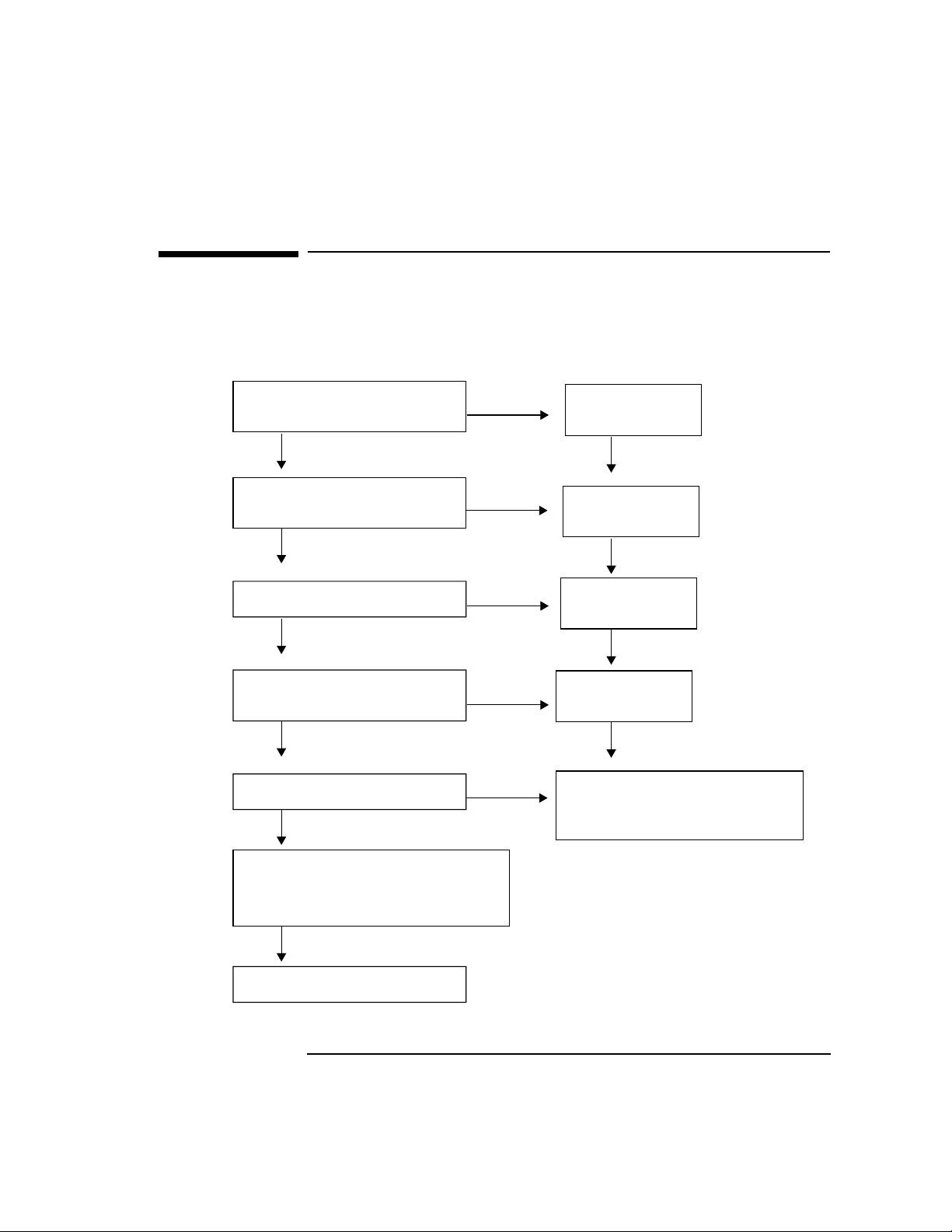
Check the following before attempting to run the FTAM tests.
Figure 1-1 FTAM Pre-Test Checklist
Interoperability Testing
FTAM Pre-Test Checklist
Is the local stack running
over the appropriate link?
Yes
Is the FTAM
responder daemon running?
Yes
Is the remote stack running?
Yes
Is the FTAM service
running on the remote?
Yes
Is FTAM logging enabled?
Yes
No
No
No
No
No
Start the
local stack.
Start
FTAM.
Start the
remote stack.
Start FTAM
on the remote.
Start logging.
Type:
/usr/sbin/nettl -start
Determine Presentation Address.
Includes P-Selector, S-Selector,
T-Selector, and Network Address.
Start the FTAM Tests.
Chapter 1 13
Page 14

Interoperability Testing
FTAM Interoperability Testing
FTAM Interoperability Testing
This procedure invokes FTAM through osidiag to provide as much
information as possible about errors that might occur.
FTAM Connectivity Test
The steps below describe how to test FTAM connectivity between the
local and remote node.
1. From root, type osidiag and select “FTAM TESTS.”
2. Create a result file.
3. Select “Connect” from the FTAM menu.
4. Enter Initiator Identification (your login information for the remote
node).
• Change ID field from local login name to remote unless login on
remote is the same.
• Enter initiator password associated with remote login.
5. Press Done.
6. Enter Presentation Address for remote node.
7. Go to the “FTAM File Transfer Test” on page 15.
14 Chapter 1
Page 15

Interoperability Testing
FTAM Interoperability Testing
FTAM File Transfer Test
After a successful FTAM connect test. Follow the steps below to do an
FTAM file transfer.
1. From the FTAM menu, create a new result file.
2. Select “Low Level Transfer.”
3. The initiator ID parameters are displayed.
a. Leave first ID set to local login.
b. Set first password to your local password.
c. Leave second set unchanged.
d. Press Done.
4. Leave source Presentation address unchanged. Press Done.
5. Leave destination address unchanged. Press Done.
6. If your system has a “message of the day” configured, leave the source
and destination file names unchanged. If your system does not have a
“message of the day” configured, overwrite the source file name with a
valid name.
7. Check “TEST STATUS” near the end of the report.
If the status is “PASSED,” FTAM verification is complete.
If the status is “FAILED,” see “Interpreting FTAM Errors” on page
16, make your corrections, then re-run this test.
Chapter 1 15
Page 16

Interoperability Testing
Interpreting FTAM Errors
Interpreting FTAM Errors
Table 1-1 may help you to find what caused your FTAM test to fail.
1. Check the field labeled “Diagnostic”.
If this field is present, look for a text string labeled “further details”
for the cause.
2. Look at the line after “FAILED”. The operation that failed is listed.
Table 1-1 FTAM Call Errors
FTAM Call Reason Corrective Action
ft_aeactivation() FTAM not correctly
installed.
OTS stack not up. Run the Status operation
ft_connect() Incorrect address
specified.
Incorrect User ID. Check user name and
Remote stack not up. Recheck stack.
Responder not running. Repeat the verification
Lower Layer Problem. Go back to the step you were
ft_select() Incorrect source file
name.
Run swverify on the FTAM
fileset to verify that all
components are installed.
under Session or Transport to
verify.
Recheck the value of the
Presentation address specified
and the value configured for
the remote.
password, usually corresponds
to the remote.
described in the pre-test
section.
on and continue.
Check the source file name
and correct.
16 Chapter 1
Page 17

Interoperability Testing
Interpreting FTAM Errors
FTAM Call Reason Corrective Action
ft_create() Permission problem or
incorrect directories were
specified in the path for
the destination file name.
ft_sdata() Transfer file too large.
(Error code 101 Buffer
too large error).
ft_xxx() Uncommon points of
error; or, if an abort
indication is received, the
remote went down for
some reason.
Check the permissions and
the directories specified.
Rerun the test with a smaller
file or use the High Level
Transfer test.
Check the remote stack and
FTAM responder if an abort
indication is indicated.
Chapter 1 17
Page 18

Interoperability Testing
Testing APRI Interoperability
Testing APRI Interoperability
The steps below describe how to test the ACSE/Presentation and ROSE
(APRI) layer connectivity between the local and remote node. Use this
only if you are developing APRI programs and wish to verify connectivity
at this layer.
1. Log on as root.
2. Perform the pre-test checklist.
3. Perform APRI test - Client Mode.
4. Perform APRI test - Server Mode (optional).
5. If osidiag cannot find a default local application title, perform
“Specifying Application Titles.”
6. Interpret errors.
18 Chapter 1
Page 19
APRI Pretest Checklist
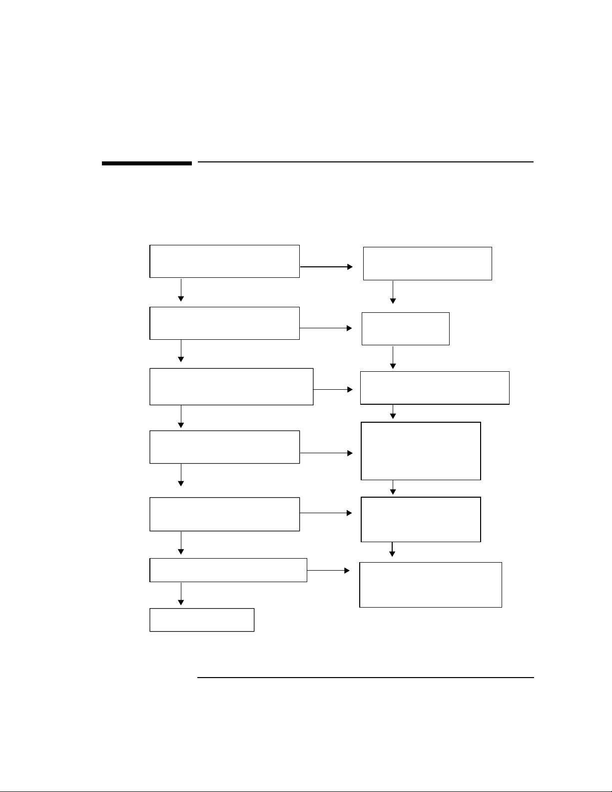
Check the following before attempting the APRI Interoperability tests.
Figure 1-2 APRI Pre-Test Checklist
Interoperability Testing
APRI Pretest Checklist
Is the local OTS
stack up?
Yes
Is the stack up on
the remote system?
Yes
Do you have the
Remote Presentation Address?
Yes
Do you have the proposed
context list for the remote?
Yes
Do you have the application
context expected by remote?
Yes
No
No
No
No
No
Type otsstart
to bring up the system.
Start the
remote stack.
Get it from the
Remote System Worksheet.
Determine context.
Default object IDs:
ACSE {2 2 1 0 1}
Arbitrary {2 1 9999 1}
Determine context.
Default object ID:
{2 1 9999 1}
Do you have the local NSAP?
Start APRI Tests.
Chapter 1 19
No
By default, osidiag binds
to CNLS over LAN,
if one is configured.
Page 20

Interoperability Testing
Running APRI Tests (Client Mode)
Running APRI Tests (Client Mode)
The following steps verify APRI connectivity and interoperability with a
remote node.
If the remote is not capable of receiving connections, or you want to test
the remote’s ability to establish connections, follow the instructions in
“Running APRI Tests (Server Mode)” on page 21.
1. From root, type /opt/ots/bin/osidiag and select
“ACSE/Presentation or ROSE Tests.”
2. Create a result file.
3. Make sure a server application is running on the remote. Then, select
“Connect” from the Test Case menu.
4. Enter Presentation Address when prompted.
NOTE osidiag will display the local address by default. The default P, S, and T
selectors are given in ASCII surrounded by double quotes. If the address
you must use is specified in hexadecimal rather than ASCII, then omit
the double quotes (for example, 22003176).
5. Enter Proposed Contexts when prompted.
6. Enter Application Context when prompted.
7. For ROSE only: Enter the context identifiers when prompted.
8. Check the “TEST STATUS” near the end of the report.
If the status is “PASSED,” you have successfully communicated with
the remote node and are finished with this section.
If the status is “FAILED , ” see “Interpreting APRI Errors” on page 22,
and find problem.
If you find the error, rerun this test.
If you cannot find the error, enable tracing. See “Tracing and Logging
through /opt/ots/bin/osidiag” on page 62 for more information.
9. Go to the APRI Tests (Server Mode). (Optional)
20 Chapter 1
Page 21

Interoperability Testing
Running APRI Tests (Server Mode)
Running APRI Tests (Server Mode)
If the remote is not capable of receiving connections, or you want to test
the remote’s ability to establish connections, follow these instructions.
1. From root, type /opt/ots/bin/osidiag -w 300 (the -w 300
allows 300 seconds to get the client ready once the server is started),
and select “ACSE/Presentation or ROSE Tests.”
2. Create a result file.
3. Select “Server...” from the Test Case menu.
4. For ROSE only: Enter the Presentation context identifiers to be used
as ROSE contexts.
5. For ROSE only: Leave the autorespond to ROSE default set to “Y”.
6. Generate the connection from the client side via the remote
application. Follow steps in the APRI Tests (Client Mode) if an HP
system.
7. Check the “TEST STATUS” near the end of the report.
If the status is “PASSED,” you have successfully communicated with
the remote node and are finished with this section.
If the status is “FAILED , ” see “Interpreting APRI Errors” on page 22,
and find the problem.
If you find the error, rerun the server test and rerun the client test on
the remote to connect to this server.
If you cannot find the error, enable tracing on the local node. See
“Tracing and Logging through /opt/ots/bin/osidiag” on page 62 for
more information.
Chapter 1 21
Page 22

Interoperability Testing
Interpreting APRI Errors
Interpreting APRI Errors
Table 1-2 describes possible errors and corrective actions if an error
occurs during a call to APRI.
Table 1-2 APRI Call Errors
APRI Call Reason Corrective Action
ap_open() Incorrect installation or OTS
stack is not up.
ap_set_env() Incorrect address specified.
(parameter ap_my_psap)
ap_poll() Time out (osidiag defaults to
30 seconds for indication or
confirmation).
Unanticipated primitive
(osidiag received an
indication it did not expect.)
ap_rcv(A_PABORT_IND) Incorrect remote address. Recheck remote
ap_rcv(A_ABORT_IND) The application on top of the
Presentation layer detected
some problem. An abort may
also be sent by the HP
provider if the specified
address is valid, but no
process is currently accepting
connections.
Run otsstat to see if
OTS stack is up. Run
otsstart to start OTS
stack.
Recheck the value of
ap_my_psap.
Increase time if needed.
Check osidiag display
immediately after the
call to ap_poll().
address; check that local
NSAP is on same subnet
as the destination
system.
Examine the output of
the remote application
for further information
as to why the abort was
sent.
22 Chapter 1
Page 23

Interoperability Testing
Interpreting APRI Errors
APRI Call Reason Corrective Action
ap_rcv(A_ASSOC_CNF) Your connect request arrived
at the remote, but the remote
did not like one of your
proposed values or it is not
available to service
connections. The confirmation
carries three pieces of
information: the result, the
source (if rejected), and a
diagnostic code.
ro_bind() The values you specified are
not compatible with those
negotiated.
Examine the diagnostic
code for the course of
action.
Verify that the values
for ap_p_ctx_list and
rose_pci_list are
consistent.
Chapter 1 23
Page 24

Interoperability Testing
Testing Session Interoperability
Testing Session Interoperability
The steps below describe how to test the session layer connectivity
between the local and remote node. Use this only if you are developing
session programs and wish to verify connectivity at this layer.
1. Log on as root.
2. Perform the pre-test checklist.
3. Perform Session tests - Client Mode.
4. Perform Session tests - Server Mode (optional).
5. If osidiag cannot find a default local application title, perform
“Specifying Application Titles.”
6. Interpret errors.
24 Chapter 1
Page 25
Session Pre-Test Checklist
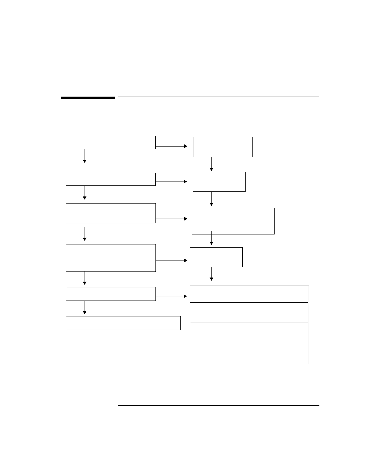
Figure 1-3 Session Pre-Test Checklist
Interoperability Testing
Session Pre-Test Checklist
Is OTS stack up?
Yes
Is the remote stack up?
Yes
Do you have the
session address?
Yes
Does remote have the
remote ready to accept
a connection?
Yes
Do the session IOP tests.
Perform Session Tests - Client Mode.
No
No
No
No
No
Start OTS
using osistart.
Start the
remote stack.
Get the address made up
of S-Sel, T-Sel, and
Network Address.
Start FTAM
on the remote.
Is the remote HP? Run osidiag
as server on the remote.
Is the remote non-HP? Run demo or
other Session application.
Does Remote only initiate activity?
Prepare local node as a server
("Perform Session Tests - Server
Mode"), then run remote Client
application.
Chapter 1 25
Page 26

Interoperability Testing
Running Session Tests (Client Mode)
Running Session Tests (Client Mode)
Normally you use this list of steps to verify connectivity and
interoperability with a remote node. If the remote is not capable of
receiving connections, or you wish to test the remote’s ability to establish
connections, follow the instructions in “Running APRI Tests (Server
Mode)” on page 21.
1. From root, type /opt/ots/bin/osidiag and select “Session Tests.”
2. Create a result file.
3. Make sure a server application is running on the remote, then: Select
“Connect” from the Test Case menu.
4. Enter the destination Session Address when prompted. NOTE:
osidiag will display the local address by default.
5. Check the “TEST STATUS” near the end of the report.
If the status is “PASSED,” you have successfully communicated with
the remote node and are finished with this section.
If the status is “FAILED,” see “Interpreting Session Errors” on page
28 to find the problem.
If you find the error, rerun this test.
If you cannot find the error, enable tracing. See “Tracing and Logging
through /opt/ots/bin/osidiag” on page 62.
6. Go to “Running APRI Tests (Server Mode)” on page 21 (Optional).
26 Chapter 1
Page 27

Interoperability Testing
Running Session Tests (Server Mode)
Running Session Tests (Server Mode)
If the remote is not capable of receiving connections, or you wish to test
the remote’s ability to establish connections, follow these instructions.
1. From root, type /opt/ots/bin/osidiag -w 300 (the -w 300
allows 300 seconds to get the client ready once the server is started),
and select “Session Tests”.
2. Create a result file.
3. Select “Server...” from the Test Case menu.
4. Generate the connection from the client side via the remote
application. Follow steps in “Running APRI Tests (Client Mode)” on
page 20, if an HP system.
5. Check the “TEST STATUS” near the end of the report. If the status is
“PASSED,” you have successfully communicated with the remote
node and are finished with this section.
If the staus is “FAILED,” see “Interpreting Session Errors” on page
28.
If you find the error, rerun the server test, then rerun the client test
on remote to connect to this server.
If you cannot find the error, enable tracing on the local node. See
“Tracing and Logging through /opt/ots/bin/osidiag” on page 62.
Chapter 1 27
Page 28

Interoperability Testing
Interpreting Session Errors
Interpreting Session Errors
Table 1-3 describes possible errors and corrective actions. The list is
sorted by the name of the function producing the error. The names are
displayed by osidiag on the line immediately after the test status.
Table 1-3 Session Call Errors
Session Call Reason Corrective Action
osi_init() Usually lack of available
swap space.
osi_rgr_rq()
osi_rgr_cf()
osi_get_event() Two common errors:
ses_pabort_id() Used to decode an incoming
Possibly stack is not up.
Another application is
already listening on this
address or has requested
exclusive access to this
address.
1. Time out - osidiag only
waits 30 seconds by default.
May indicate that the remote
is not sending any response
to your request.
2. Unanticipated primitive osidiag received an
indication that it did not
expect.
provider abort indication.
For more information see
“Protocol Reason Codes” on
page 44. The reason code
appears in the middle of the
osidiag output.
Add swap space as necessary.
Check to see if stack is up. See
if another applications is
using this address or has
exclusive access.
Verify that the remote is
indeed performing its end of
the dialog. If the timeout is
too short, it may be changed
under the utilities menu. The
name of the indication will be
displayed immediately after
the call to
osi_get_event().
Check the reason code and
correct accordingly.
28 Chapter 1
Page 29

Interoperability Testing
Interpreting Session Errors
Session Call Reason Corrective Action
ses_uabort_id() Used to decode incoming
abort indication. Indicates
the application on top of the
Session layer detected some
problem.
ses_connect_rf() Called to decode a refusal to
connection request. Indicates
that your connect request
arrived at the remote, but
remote did not like one of
your proposed values or it is
not available to service
connections. The refuse code
is displayed in the middle of
the osidiag output.
Examine the output of the
remote application for
further information as to why
the abort was sent.
Check the remote to see if it is
available to service
connections. Also check your
proposed values. For more
information on disconnect
codes and suggested actions,
See “Interpreting Transport
Errors” on page 33.
Chapter 1 29
Page 30

Interoperability Testing
Testing Transport Interoperability
Testing Transport Interoperability
The steps below describe how to test Transport layer connectivity
between the local and remote node.
1. Log on as root.
2. Perform the pre-test checklist.
3. Perform Transport tests.
4. If osidiag reports “FAILED”, see “Interpreting Transport Errors” on
page 33.
30 Chapter 1
Page 31

Transport Pre-Test Checklist
Figure 1-4 Transport Pre-Test Checklist
Interoperability Testing
Transport Pre-Test Checklist
Is the OTS stack up?
Yes
Is the remote stack up?
Yes
Do you have the remote
Network Address and
T-Selector?
Yes
Do the Transport
Interoperability Tests.
No
No
No
Start OTS
using otsstart.
Start remote stack.
Get the address from the
S-Sel, T-Sel, P-Sel, and
Network Address.
Chapter 1 31
Page 32

Interoperability Testing
Running Transport Tests
Running Transport Tests
1. From root, type /opt/ots/bin/osidiag and select “Transport
Tests.”
2. Create a result file.
3. Make sure a server application is running on the remote, then select
“Connect” from the Transport Tests menu.
4. Enter the destination Transport Selector and Network Address when
prompted. NOTE: osidiag will display the local address by default.
The default P, S, and T selectors are given in ASCII surrounded by
double quotes. If the address you must use is specified in hexadecimal
rather than ASCII, then omit the double quotes (for example,
22003176). If you are testing RFC1006 interoperability, enter the
RFC1006 NSAP for the remote system.
5. Check the “TEST STATUS” near the end of the report.
If the status is “PASSED,” you have successfully communicated with
the remote node and are finished with this section.
If the status is “FAILED,” see “Interpreting Transport Errors” on
page 33 to find the problem.
If you find the error, rerun this test.
If you cannot find the error, enable tracing. See “Tracing and Logging
through /opt/ots/bin/osidiag” on page 62.
32 Chapter 1
Page 33

Interpreting Transport Errors
The following are possible situations you may currently find yourself in.
Transport problem corrected.
If you have made a change that corrected your Transport problem, then
return to the Service Layer test that originally failed and try again.
Configuration or other change required.
If the corrective action in the following sections require you to change a
configuration parameter or make some other change, then do so and
rerun the Transport test.
Problem persists.
If you have been unsuccessful in correcting the problem, gather the
information you have collected to provide to your HP support
representative.
Table 1-4 Transport Call Errors
Interoperability Testing
Interpreting Transport Errors
Error Reason Action
t_open() The stack is most likely
not up.
t_bind() Failed to associate an
address with the transport
endpoint. Likely a
parameter error. Link
supporting this address
went down.
t_rcvdis() Called to decode a
disconnect indication.
t_look() Remote stack does not
respond for default time.
Chapter 1 33
Run status operation under
Transport menu.
Verify that the parameter
tp_my_tsap is set to “diagt” or
“diagt.NSAP” where NSAP is
valid local address. Run status
operation under Transport menu.
Check online error messages.
Check to see if one node is
configured as NULL internet and
other is not. Check for incorrect
remote network address.
Page 34

Interoperability Testing
Testing LAN (802.3 or FDDI) Interoperability
Testing LAN (802.3 or FDDI)
Interoperability
The steps below describe how to test connectivity at the Link level
(either 802.3 or FDDI LAN) between the local and remote node.
1. Log on as root.
2. Perform the pre-test checklist.
3. Perform LAN test.
4. If osidiag reports “FAILED,” see “Interpreting LAN Errors” on
page 37.
34 Chapter 1
Page 35

LAN Pre-Test Checklist
Figure 1-5 LAN Pre-Test Checklist
Interoperability Testing
LAN Pre-Test Checklist
Is the local
LAN card up?
Yes
Is the remote card up?
Yes
Do you have the Media
Access Control Address
for the remote?
No
No
No
Start the LAN
using osiadmin.
Start remote card.
Get the address by selecting
"LAN Tests," then "Status"
menu.
The MAC address is
labelled "LAN Physical
Address."
Chapter 1 35
Page 36

Interoperability Testing
Running LAN Tests
Running LAN Tests
1. From root, type /opt/ots/bin/osidiag and select “LAN Tests.”
2. Create a result file.
3. Select “Test Frames.”
4. Enter the interface name to issue the test from (lan0, lan1, etc.). The
default from the ots_subnets file can be used unless you have
multiple I/O Cards.
5. Enter the value previously retrieved for the remote MAC address in
hexadecimal (always 6 bytes - 12 hex digits). Do not include the
leading “0x” if present.
6. If the test status field says “PASSED,” proceed to “Testing Transport
Interoperability” on page 30.
If the test status field says “FAILED,” see “Interpreting LAN Errors”
on page 37.
36 Chapter 1
Page 37

Interpreting LAN Errors
The following are possible situations you may currently find yourself in.
LAN problem corrected.
If you have made a change that corrected your LAN problem, then
proceed to the OTS layer tests.
Configuration change required.
If the corrective action in the following sections require you to change a
configuration parameter, then do so and rerun the LAN test.
Problem persists.
If you have been unsuccessful in correcting the problem, gather the
information you have collected to provide to your HP support
representative.
Table 1-5 LAN Errors
Interoperability Testing
Interpreting LAN Errors
Error Reason Action
LAN Interface Name The “interface name” is
extracted from the OTS
subnet configuration. If
the device is not open, it
may have the wrong
value configured (or no
value).
open() Opens the DLPI stream
device. Device file
/dev/dlpi may not exist.
getmsg (DL_BIND_ACK) Used to set up various
options for LAN access.
Possible errors:
*Setting SSAP. Sets Link
Service Access Point. Will
fail if it is currently in use
by another osidiag
process or by OTS.
Chapter 1 37
Check the parameter
lanX_if_name from the
top of the osidiag output
and verify that this
interface exists using the
lanscan command.
Create device file using
mkdev(1M) command.
If OTS is running, make
sure OTS will not be
started when the system
comes up and reboot the
system to perform this
command.
Page 38

Interoperability Testing
Interpreting LAN Errors
Error Reason Action
getmsg (DL_TEST_CON)
getmsg (DL_UNITDATA_ACK)
putmsg (DL_TEST_REQ) The local system is not
putmsg (DL_UNITDATA_REQ) Data exceeds maximum
Receives information
from the remote either on
Receive or Test Frame
operation. Usually means
time out.
configured to use IEEE
packets.
MTU size for LAN.
Check MAC address
specified, and cabling
between the two systems.
If neither is true, check to
see if remote supports
IEEE 802.3 TEST frames.
Check and correct as
necessary using the
lanconfig(1M) command.
Use “status” in LAN Test
menu to determine MTU
size.
38 Chapter 1
Page 39

Interoperability Testing
Testing X.25 Interoperability
Testing X.25 Interoperability
The steps below describe how to test connectivity at the Network Layer
for nodes connected via X.25.
1. Log on as root.
2. Perform the pre-test checklist.
3. Perform X.25 test.
4. If osidiag reports “FAILED, ” see “Interpreting X.25 Errors” on page
42.
Chapter 1 39
Page 40

Interoperability Testing
X.25 Pre-Test Checklist
X.25 Pre-Test Checklist
Figure 1-6 X.25 Pre-Test Checklist
Is the local card up?
(Use x25stat to check.)
Yes
Is the remote card up?
Yes
Is the remote stack up?
Yes
Do you have the X.121
Address for the remote
OSI stack?
Yes
Do you have the
subaddress used by the
OSI stack?
No
No
No
No
No
Start X.25 using
osiadmin or x25init.
Start remote card.
Start the remote stack.
Type x25stat -c
to display the address.
From osiadmin, select "OTS",
"View Configuration",
and "OTS Subnetwork".
Yes
Are you using CONS
or CLNS?
40 Chapter 1
Then
Find
"snet_x25_subaddress".
Find parameters
snet_cons_x25
or
snet_clns_x25.
Page 41

Interoperability Testing
Running X.25 Tests
Running X.25 Tests
1. From root, type osidiag and select “WAN X.25Tests.”
2. Create a result file.
3. Select “Connect.”
4. Enter the value for the remote X.121 address. This value is both the
address for the remote card and any subaddress concatenated into a
single decimal number.
5. Leave the X.25 Interface name unchanged.
6. For CONS change the protocol ID to the value 03010100. For CLNS,
change the protocol ID to 81. Press Done.
7. If the test status field says “PASSED,” proceed to “Testing Transport
Interoperability” on page 30.
If the test status field says “FAILED,” see “Interpreting X.25 Errors”
on page 42.
Chapter 1 41
Page 42

Interoperability Testing
Interpreting X.25 Errors
Interpreting X.25 Errors
The following are possible situations you may currently find yourself in.
X.25 problem corrected.
If you have made a change that corrected your X.25 problem, then
proceed to the Transport layer tests.
Configuration change required.
If the corrective action in the following sections require you to change a
configuration parameter, then do so and rerun the X.25 test.
Problem persists.
If you have been unsuccessful in correcting the problem, gather the
information you have collected to provide to your HP support
representative.
Table 1-6 X.25 Errors
Error Reason Action
socket() X.25 is not installed on your
system.
bind() If OTS is running, osidiag is
not able to bind to the same
X.121 address the stack is
using.
connect() Invalid programmatic
access name.
42 Chapter 1
Install X.25.
If supported by a switch, try binding to a
different subaddress or the NULL
subaddress.
Use default or leave blank. Can also verify
the value by issuing the “Status...”
operation through the X.25 Tests.
Page 43

Error Reason Action
Interoperability Testing
Interpreting X.25 Errors
recv(*00B*) Errors related to the receipt
of an unexpected CLEAR or
RESET packet.
Some common diagnostics:
(0) No additional information - may
indicate that the request was delivered to
the remote, but it was rejected by the OSI
stack. Check Protocol ID.
(67) Call setup problem; Invalid called
address. Check addresses of the remote
and correct.
(231) Connection Rejection - NSAP
Unreachable. Check the Protocol ID and
subaddress.
Chapter 1 43
Page 44

Interoperability Testing
Reason and Refuse Codes
Reason and Refuse Codes
Protocol Reason Codes
The following are reason codes that may be logged or returned to your
program.
Session Provider Abort Reason Code
The value passed back to Session programs by the ses_pabort_id()
routine.
Transport Disconnect Reason Code
The value passed back to XTI program by the t_rcvdis() routine.
ASCE/Presentation DCNX_KO Log Message
The value shown in the second low order byte of the Cause field (f3 in
Cause = 0x0001f3ff).
Session S_REJECT Log Message
The value shown in the second low order byte of the Cause field (f3 in
Cause = 0x0001f3ff).
Transport T_REJECT Log Message
The value shown in the second low order byte of the Cause field (f3 in
Cause = 0x0001f3ff).
Network N_REJECT Log Message
The value shown in the second low order byte of the Org/Reas field (the
“08” in Org/Reas = 0108).
Table 1-7 shows the reason code value, its meaning, and possible
corrective actions.
Table 1-7 Reason and Refuse Codes
Code Meaning Action
(0) Normal disconnect Specified address may be
correct, but there is no process listening for a
connection.
44 Chapter 1
Verify that OSI services are
up in the remote. Verify that
the T-selector is specified.
Page 45

Interoperability Testing
Reason and Refuse Codes
Code Meaning Action
(0x01) Provider N-Disconnect (Transient)
Previously active network connection was
abruptly disconnected. Congestion at TSAP
Some vendor’s equipment may indicate that
the application above transport is not
capable of receiving any more connections.
(0x02) Provider N-Disconnect (Permanent)
Previously active network connection was
abruptly disconnected. Transport User Not
Attached to TSAP Indicates that the address
specified is valid, but that no process capable
of receiving connections is active.
(0x03) Provider N_Reject (Transient) Network
connection could not be established.
Address Unknown
Address specified was incorrect.
(0x04) Provider N_Reject (Permanent) Request to
establish a network connection was rejected.
(0x05) Provider N_Reject (QOS unavail/ Transient)
The X.25 card or the switch
may have gone down.
Check the remote for any
further logged information.
The X.25 card or the switch
may have gone down.
Verify that server is active on
remote.
Check the NSAP and Tselector.
Check for facility rejection,
non-use of fast select, reverse
charge failure, switch or PDN
out of order.
QOS negotiation failed for this connection.
(0x06) Provider N_Reject (QOS unavail/
Permanent)
QOS negotiation failed for this connection.
(0x07) N-Reject (NSAP unreachable/ Transient)
Network connection could not be established
because there were not enough VCs or
resources available.
Chapter 1 45
Use x25stat to examine the
state of the network card.
Check log file for OTS
messages.
Page 46

Interoperability Testing
Reason and Refuse Codes
Code Meaning Action
(0x08) N-Reject (NSAP unreachable/ Permanent)
Network connection could not be established
because the X.121 address was incorrect.
(0x09) N-Reset from NS Provider (No Reason)
Network connection was reset.
(0x0a) N-Reset from NS Provider (Congestion)
Network connection was reset.
(0x0b) N_Reject (Address Unknown)
No destination or route entry exists for the
given NSAP. Network connection cannot be
established.
(0x12) Disconnect for NS User Remote Transport
layer encountered a failure and abruptly
released the network connection.
(0x14) User N_Reject (Transient)
The remote Transport layer refused this
network connection request.
Use osiadmin or otsshowes
to examine the configured
X.121 address for this NSAP.
Verify if remote is up and
listening on the configured
address.
No recognized diagnostic is
provided.
X.25 diagnostic indicates
provider was a problem.
Use osiadmin or otsaddes
to configure the destination
system.
(0x15) User N_Reject (Permanent) The remote
Transport layer refused this network
connection request.
(0x16) User N_Reject (QOS unavail/ Transient)
QOS negotiation failure
(0x17) User N_Reject (QOS unavail/ Permanent)
QOS negotiation failure
(0x18) N_Reject ((Unrecognized NS-user- data)
46 Chapter 1
Page 47

Interoperability Testing
Reason and Refuse Codes
Code Meaning Action
(0x1a) Network Reset from NS User (Resynch)
Network connection was reset.
(0x20) Undefined reason, unknown origin Indicates
some X.25 problem.
(0x21) Invalid Parameter (OTS Kernel)
An encoded parameter is invalid.
(0x22) External Protocol Error (OTS Kernel)
Failure decoding facility information.
(0x23) Invalid Internal State (OTS Kernel)
A network primitive was received or is to be
sent in an unexpected state.
(0x24) Facility or Data F ield Overflow (OTS Kernel)
Processing of the facility fields indicated
failure
(0x41) X.25 Facility Requested not Allowed
The configured X.25 facilities do not match
those of the provider.
X.25 diagnostic indicates
resynchronization was
requested.
Check for down card on local
or remote, switch, or facilities
negotiation.
Check for NSAPs that are too
large or missing.
An error should be logged
describing the protocol error.
An error should be logged
describing the protocol error.
An error should be logged
describing the protocol error.
Determine the facilities
available and reconfigure
OTS and X.25 to use the
appropriate set.
(0x42) Could not Access X.121 Address of Remote
The X.121 address mapped to the NSAP you
specified is incorrect or the remote system is
down.
(0x81) Remote Transport Entity Congestion at
Connect Time
Indicates that no problems were detected
with the Transport layer, but user of service
may have sent an abort or other higher level
error.
Chapter 1 47
Reset the remote system or
reconfigure the OTS routing
table appropriately.
Page 48

Interoperability Testing
Reason and Refuse Codes
Code Meaning Action
(0x82) Connection Negotiation Failed
May be a problem with the classes specified
(transport over CONS error).
(0x83) Duplicate Source Reference for Same NSAP
This is a protocol error.
(0x84) Mismatched References
Either a protocol error, or may indicate that
the remote stack was taken down and
brought back up while existing connections
remained.
(0x85) Protocol Error Check any logged
(0x88) Connection Request Refused on this Network
Connection
The level of multiplexing configured for the
local node may not be compatible with that
on the remote.
Check to see if remote only
uses class 0. If so you might
reconfigure the local stack to
force class 0.
The caller must generate a
unique reference number for
each connection it forms.
Check the state of the remote
stack.
information on the remote
side. Also verify the stack was
not being brought up at the
time.
On HP systems, examine the
Transport over CONS
parameters
tpcons_max_con_mux_in
and
tpcons_max_con_mux_out
and change if max out exceeds
max in.
(0x8A) Header or Parameter Length Invalid
Indicates a protocol error.
(0xE4) X.25 Network Error or Network Down Run x25stat to determine
48 Chapter 1
Check log information on
remote.
the status of the X.25 link.
May need to restart X.25 or
reset other X.25 hardware.
Page 49

Interoperability Testing
Reason and Refuse Codes
Code Meaning Action
(0xE7) Problem Accessing X.25 Subaddress of
Remote
Subaddress portion of X.121 from the OTS
routing table is incorrect or the remote is not
up.
(0xE8) NSAP not Configured
Network address portion of the address
specified is not configured in the routing
table. (Not usually LAN)
(0xF0) Protocol Error Detected by Remote’s
Transport
Remote encountered an error decoding one o
the Transport PDUs sent by us.
(0xF1) Protocol Error Detected by Remote’s Session
Remote encountered an error decoding one of
the Session PDUs sent by us.
(0xF3) Invalid Address or Permanent Transport
Error
Usually returned when an invalid T- selector
or Network Address is given. Could also get
when remote stack is not running or the
remote’s X.121 address is not associated with
its NSAP.
Correct the routing table or
bring up the remote.
Configure remote X.25 using
osiadmin.
Generate a trace and contact
your HP support
representative.
Generate a trace and contact
your HP support
representative.
Use osiconf to associate
X.121 address with NSAP.
(0xF4) Invalid Address or Permanent Session Error Check address specified, and
state of remote stack to
ensure it is running.
(0xF6) X.25 Unavailable or Transient Transport
Error
(0xF7) Transient Session Error Verify status of remote stack.
Chapter 1 49
Verify that X.25 is up by
running x25stat operation.
Page 50

Interoperability Testing
Reason and Refuse Codes
Code Meaning Action
(0xF9) Protocol Error Detected by Local Transport
Error encountered decoding a PDU sent by
the remote Transport entity.
(0xFA) Protocol Error Detected by Local Session
Error encountered decoding a PDU sent by
the remote Transport entity.
(0xFC) Insufficient Resources for Local Transport
Stack experiencing resource problems.
(0xFD) Insufficient Resources for Local Session
Stack experiencing resource problems.
(0xFE) Insufficient Resources for Local
ACSE/Presentation
Stack experiencing resource problems.
Generate a trace and contact
your HP support
representative.
Generate a trace and contact
your HP support
representative.
Examine other OTS
processes running. Contact
HP support representative if
condition persists.
Examine other OTS
processes running. Contact
HP support representative if
condition persists.
Examine other OTS
processes running. Are you
near the 448 connection limit?
Contact HP support
representative if condition
persists.
(0xFF) Local User Error
Usually caused by overriding parameter
default values, Could result from trying to
run an operation in the wrong state.
(01-EF
X.25
F0-FF
Transport
Code Unknown
An unrecognized error code was received.
50 Chapter 1
Check parameters values you
changed.
Examine documentation of
other vendor for disconnect
reason codes. If X.25 range,
run an X.25 connection test,
the diagnostic information
may be helpful.
Page 51

Session Refuse Codes
Table 1-8 describes the meanings defined by ISO 8327 for the reason
codes carried on a negative Session connect confirmation. These values
are logged after S_CONNECT_Resp (Negative) message, and on return
from the ses_connect_rf() library call.
Table 1-8 Session Refuse Codes
Code Meaning
0 Reason not specified.
1 Rejection by called Session service user due to
temporary congestion.
2 Rejection by called Session service user. The
following octets may be used for up to 512 octets of
user data.
81 SSAP identifier unknown.
82 Session service user not attached to SSAP.
Interoperability Testing
Reason and Refuse Codes
83 SBM congestion at connect time.
84 Proposed protocol versions not supported.
Chapter 1 51
Page 52

Interoperability Testing
To Create A Result File
To Create A Result File
Use the following steps to create a result file. It can be reached from
several osiadmin menus.
1. Select “Utilities” from a services menu.
2. Select “Open Result File”.
3. Enter the name of your file (for example, /tmp/ftam.res).
4. Press Done.
5. Press the space bar when a message appears showing the file was
opened.
If the message shows an error, check the name you specified.
6. Press Previous Menu.
52 Chapter 1
Page 53

2 Problem Solving
Information and procedures for identifying and troubleshooting
problems that you may encounter using Hewlett-Packard’ s OSI products.
53
Page 54

Problem Solving
Basic Steps
Basic Steps
NOTE If the problem you encounter occurs only when communicating with
another system, see Chapter 1, “Interoperability Testing,” on page 11.
1. Interpret the initial error. To find more information about the specific
error, see “Interpreting Errors” on page 55.
2. Determine the status of components. Make sure all the OSI product
components are up and running. See “Checking System Status” on
page 56.
3. Verify operation. If all components report that they are up and the
problem persists, verify the ability of the link (X.25, 802.3 or FDDI),
the stack, and the specific service you are using to communicate. See
“Running Verification Tests” on page 58.
4. Gather more information. If the information from the basic
verification test was insufficient to diagnose the problem, then you
can get additional information through Hewlett-Packard’s tracing
and logging facilities. See “Collecting Troubleshooting Data” on page
61.
5. Validate configuration. If you have not already done so, run
osiconfchk to validate the configuration. For a description of this
tool, see Chapter 3, “Using OSI and OTS Tools,” on page 71. Also
check the possible problems listed in “Common Configuration
Mistakes” on page 65.
6. Validate installation. If the system behavior is still not correct, check
that your software installation has not been corrupted. The tool
swverify(1M) performs this task.
7. Submit information to HP. If you were not successful in diagnosing
and correcting the problem, contact your HP support representative.
See “Submitting Problem Information to HP” on page 70.
54 Chapter 2
Page 55

Problem Solving
Interpreting Errors
Interpreting Errors
This section describes where you should look to find more information
about an error you encountered. Table 2-1 gives the places where you
may encounter errors and how to interpret them.
Table 2-1 Interpreting Errors
Where Action
osidiag You will find a description of how to interpret errors at the end of
each section in Chapter 1, “Interoperability Testing,” on page 11.
nettl log files Many errors contain detailed text describing the problem. Some
common logged errors are described at the end of this chapter.
User applications Errors received in applications you write are passed back through
return codes. You may want to use the API tracing facility for the
interface. The nettl log file many also contain information. You
could also increase the logging level and reproduce the problem. See
“Tracing and Logging through /opt/ots/bin/osidiag” on page
62.
FTAM
Interactive
Commands
X.400 Commands Refer to the Managing X.400—Administrator’s Guide.
OSI/OTS
Administrative
Commands
System Panics Panics occur when an irrecoverable error is detected by the HP-UX
These errors are described in the HP FTAM/9000 User’s Guide and
the HP FTAM/9000 Reference Manual.
These errors are produced from commands like otsstart and
osiconfchk. Descriptions of these errors can be found online. Also
look in the log files in /var/opt/ots.
operating system. At reboot after a panic, a copy of the state of the
system will be saved by savecore. See
/etc/rc.config.d/savecore. You may need to create a special
directory for savecore to actually save the image to disk.
Interpreting panics is done by your HP support representative or the
factory.
Chapter 2 55
Page 56

Problem Solving
Checking System Status
Checking System Status
There are several tools that allow you to check if the links, stack, and
services are up and running. Perform the following steps to verify that
your local system is up.
Status Check 1
1. Run otsstat to verify the status of OTS and its attachment to the
underlying links.
2. If status says “RUNNING,” go to Status Check 2.
3. If status says “NOT RUNNING,” start the stack using otsstart or
osiadmin.
If still “NOT RUNNING,” run osiconfchk. This indicates a
configuration problem.
Status Check 2
1. If one or more LAN cards are configured, run lanscan to show status
of all LAN cards on the system.
2. If net interface state shows “DOWN,” the card is disabled. Restart the
card by running osiadmin or ifconfig. If the card is still down
after starting it, check for hardware or cabling problems.
3. If OTS still shows link is “DOWN” while lanscan shows it as up,
verify that the configured interface name shown by otsstat matches
that shown by lanscan.
Status Check 3
1. If one or more X.25 cards, run x25stat, against each card’s device file
name.
2. If the message says “not currently active,” start the card using
osiadmin or x25init.
3. If the message says “Level 2 is DOWN,” there is a communication
problem between the card and the switch. Check the cabling and the
configuration of the device the X.25 card is connected to.
56 Chapter 2
Page 57

Problem Solving
Checking System Status
Status Check 4
1. If you are using the FTAM Service, run osistat to verify that the
shared memory segment is present and to display the number of
currently active FTAM applications. See Chapter 3, “Using OSI and
OTS Tools,” on page 71, for more information on osistat.
2. If you are using FTAM, then the count of “Active FTAM responder
service providers” should be one or more. If not, then run osiadmin
or osistart to start FTAM.
3. If osistat indicates that it is “Unable to access the shared- memory
segment” formatting, you may need to regenerate the kernel to
increase the available amount of shared memory or semaphores.
Status Check 5
1. If you are running X.400, then type /opt/x400/bin/x4stat to
display the X.400 processes that are enabled.
2. If the process status of any component displayed is “not running!”
then issue the command x4start.
3. Use the Managing X.400—Administrator’s Guide if problems persist.
Chapter 2 57
Page 58

Problem Solving
Running Verification Tests
Running Verification Tests
The verification strategy described here follows a bottom up approach. It
first checks the ability of the links to communicate, then the OTS
Transport Layer, and last the desired service.
All the verification tests use osidiag. Testing the X.400 services may
alternatively be performed through x4admin or the X.400 tools described
in Managing X.400—Administrator’s Guide.
osidiag may be invoked directly from the command line, or through
osiadmin by selecting “Test Connectivity->” for the appropriate layer.
NOTE Hewlett-Packard strongly recommends that you run these verification
tests even if the problem you are troubleshooting is seen through a
user-written application. If the verification tests fail, then there is a
general network problem that you should correct. If these tests pass,
then the problem is related to your program's behavior. For a description
on how to further analyze program-specific problems, see “Collecting
Troubleshooting Data” on page 61.
Link Verification
For X.25
1. For X.25, run the “Loopback...” test under osidiag’s “X.25 Test
Cases.”
2. If you have multiple X.25 cards, run this test under osiadmin, so
that osidiag will use the correct default values.
3. If OTS is not configured to use subaddressing, you will not be able to
run this test when OTS is running. The error you see is “Address
already in use.” Try running the “Connect...” test instead, making
sure the Protocol ID field is blank and not “dx25.”
4. If you encounter errors, see “Interpreting X.25 Errors” on page 42.
For LAN
1. For LAN, run the “Test Frames...” test under osidiag’s “LAN Test
Cases.”
58 Chapter 2
Page 59

Problem Solving
Running Verification Tests
2. If you have multiple LAN cards, run this test under osiadmin, so
that osidiag will use the correct default values
3. If you encounter errors, see “Interpreting LAN Errors” on page 37.
OTS Transport Verification
To verify OTS Transport, do the following:
1. Go to “Transport Tests-” under osidiag and select the “Loopback...”
test.
2. Overwrite the Network Address if you want to test a subnetwork
other than the default. By default, osidiag will run over the first
LAN subnet configured. If no LAN is configured, then it will run over
the first WAN subnet configured.
3. If you encounter errors, see “Interpreting Transport Errors” on page
33.
Run this test for each subnetwork you have configured. The subnetwork
used is determined indirectly by the network address you specify in step
2.
The other network address values can be found on your Local
Configuration Worksheets. Alternatively, you can find the other local
addresses by doing the following:
1. Select the “Status...” test from the “Transport Test Cases” menu.
2. Look for fields labeled snet_local_net_address. These are the
local network addresses you have configured for your subnetworks.
Service Verification
The verification steps for the X.400 and FTAM products are given in
more detail in the respective “Installing and Configuring” manuals. The
general steps for service verification are outlined below.
1. From osidiag, select the service to test. Or from osiadmin, select
“Test Connectivity...” in the menu for the service to test.
2. Select the “Loopback” test from the menu. For FTAM, use “Connect”
instead of loopback.
Chapter 2 59
Page 60

Problem Solving
Running Verification Tests
3. Use the default configured values that osidiag presents. For more
information about a parameter, press the “Help” key when in the field
in question.
4. If you encounter errors, see “Interpreting Errors” for the specific layer
in Chapter 1, “Interoperability Testing,” on page 11.
60 Chapter 2
Page 61

Collecting Troubleshooting Data
If the information already given was not sufficient to isolate and correct
the problem, use the tracing and logging facilities to gather more
information.
The method you use to gather tracing and logging information will
depend on the error that is produced. Table 2-2 lists the possible
methods.
Table 2-2 Troubleshooting Methods
Problem Solving
Collecting Troubleshooting Data
Type of
Error
osidiag If the problem is reported during a run of osidiag, then use the tracing
and logging utilities provided by osidiag. This procedure is described in
the section “Tracing and Logging through /opt/ots/bin/osidiag” on
page 62.
X.400 If the problem occurs through an X.400 application, then follow the tracing
procedures described in the Managing X.400—Administrator’s Guide.
User
Application
If the problem occurs through a user-written application, then there are two
facilities that can give you further information. This procedure is described
in the section “Tracing and Logging User Applications” on page 63.
Troubleshooting Method
Chapter 2 61
Page 62

Problem Solving
Tracing and Logging through /opt/ots/bin/osidiag
Tracing and Logging through
/opt/ots/bin/osidiag
osidiag (located in the /opt/ots/bin directory) provides the ability to
automatically capture nettl trace and log information and append it to
the output for a test operation. osidiag also allows you to copy the
results displayed to the screen to a result file. The following steps
describe how to enable both facilities through osidiag.
1. Invoke osidiag either directly or through osiadmin and go to the
Utilities menu.
2. Select “Open Result File” and enter a file to save the results of the
test operation (for example, /tmp/ftam.res). The file specified will
be overwritten if it already exists.
3. Select “Tracing and Logging.”
4. Enable logging for OTS, by placing a “Y” after its name in the pop-up
window. Enable tracing for the layer being tested and the layer below.
So, for FTAM you would enable FTAM and ACSE/Presentation. For
Transport, you would enable Transport and Network. Use the “Help”
facility for more information about a particular flag. Press Done on
the Trace and Log screen after setting the appropriate fields to “Y.”
5. Use the default values presented for the log and trace levels by
pressing Done on these screens, and then exit the Utilities menu.
6. Now rerun the test you are gathering information for. The results of
the logging and tracing will be displayed on your screen as well as
copied to the file you specified in step 2.
To analyze the errors logged, see “Common Logged Errors” on page 67.
The trace information produced may be useful to your HP support
representative. Interpreting traces requires a good understanding of the
various OSI protocol internals. Some information on trace interpretation
is given at the end of the “Session,” “OTS,” “X.25,” and “LAN” sections of
Chapter 1 “Interoperability Testing”.
62 Chapter 2
Page 63

Tracing and Logging through /opt/ots/bin/osidiag
Tracing and Logging User Applications
Two facilities exist to provide more data about the behavior and errors
encountered by your application, API tracing and nettl.
API Tracing This facility allows you to trace the calls your
application makes to the Application Programmatic
Interface. The mechanism to perform API tracing is
described in the programmer's guide for the service you
are using.
nettl The nettl command allows you to enable logging and
tracing in the OTS stack as well as for the FTAM
service. The syntax of the nettl and netfmt
commands is given in the nettl(1M) and netfmt(1M)
man pages.
Hewlett-Packard recommends that you enable warning and error logging
for stack components at and below the service you are using. Table 2-3
shows the entities on which you should enable logging for gathering
information.
Table 2-3 Logging and Tracing Entities
Problem Solving
Service/Layer Entities to Log
X.400* X.400 Logging facilities
+ OTS entities
+ Link entity
FTAM FTAM_VFS FTAM_USER
FTAM_INIT FTAM_RESP
+ ULA entities
+ OTS entities
+ Link entity
APRI ACSE_PRES
+ OTS entities
+ Link entity
OTS SESSION TRANSPORT NETWORK OTS
LAN 802.3 NS_LS_DRIVER
X.25 SX 25 L2, SX25L3 (Level 2 and 3 link tracing)
Chapter 2 63
Page 64

Problem Solving
Tracing and Logging through /opt/ots/bin/osidiag
Service/Layer Entities to Log
FDDI FDDI
* The tracing and logging of X.400-specific components can be done
through x4admin, and is described in the Managing
X.400—Administrator’s Guide. Tracing and logging of OTS and the link
is still performed through nettl for X.400.
Tracing is only recommended if you have a good understanding of the
protocol internals. When used, it is useful to trace at the layer your
application uses and one level below.
For instance , to trace an FT AM application, you might enable tracing for
the FTAM entities and ACSE/Presentation. To trace an XTI application,
you might enable Transport and Network tracing. The kind of tracing
will usually be PDU In, PDU Out, Header In, and Header Out.
To analyze the errors logged, see “Common Logged Errors” on page 67.
64 Chapter 2
Page 65

Problem Solving
Common Configuration Mistakes
Common Configuration Mistakes
The following list describes some common configuration errors that may
result in failure during verification. The errors are grouped by the
configuration file that contains them.
See the “OTS and Related Parameters” chapter in the OSI Transport
Services manual for detailed information about all the parameters.
ots_dests Common Mistakes
• Mistyped dest_net_address or the dest_phys_address, will
cause a fail in your attempt to connect.
• Destination entries must be made in order for loopback to work over
both CONS and CLNS/X.25. Be sure to include any X.25 subaddress
when specifying the physical address.
• Destination entries must be made in order for loopback to work over
CLNS/ LAN when CLNP Subset 0 is used. In other cases, destination
entries for LAN should be avoided.
• Specifying the incorrect outgoing subnetwork for a destination, will
cause a fail to connect.
• When specifying reverse charging for X.25, the remote must be
configured to accept it. Otherwise, it will reject your connection.
ots_subnets Common Mistakes
• Mistyping your local address will cause the remote systems to be
unsuccessful in connecting with you.
• Incorrect CLNP subset for LAN. This can prevent interoperability
with other systems on the LAN. See the parameter
snet_clnp_subset.
• LAN-based networks with a large number of nodes (over 200), should
have the parameter snet_max_es_entries increased. Not doing so
can result in failure to establish connections with other systems.
Chapter 2 65
Page 66

Problem Solving
Common Configuration Mistakes
• Incorrect interface name. Specifying an interface name that is not
configured will result in warnings, but OTS will still start. If
otsstat indicates any links are “NOT RUNNING,” verify these
names.
ots_parms Common Mistakes
• If close to the limit of connections available (448 over LAN , 4096 over
X.25) through OTS, the ses_reuse_tp_con flag may hold open
connections you need to recycle.
• If using CONS/X.25, ensure that the Transport class OTS requests is
acceptable to the remote. The tpcons_pref_mux_class parameter
determines whether you use class 2 or 4. The parameter
tpcons_tp0_only forces class 0.
• Some vendors do not accept the OSI Transport protocol ID carried on
X.25 connection requests. This can be disabled with
tpcons_null_pid.
local_app Common Mistakes
• Setting the maximum invocations, or inbound associations too low
can result in your failing to receive or create connections with remote
FTAM applications.
• If you manually edit these files rather than using osiadmin, you
should be sure that all FTAM application titles match the
ftam_ddn_lookup_path parameter.
remote_app Common Mistakes
• Mistyping a remote application title or alias for FTAM will result in
your connection failing.
• Mistyping a remote presentation address for FTAM will result in
your connection failing.
66 Chapter 2
Page 67

Common Logged Errors
The following list describes some of the more common errors logged by
OTS that you can encounter. These errors are sorted by the subsystem
name and the message ID as it appears in the log.
Table 2-4 Subsystem OTS
Error Description
Problem Solving
Common Logged Errors
[9600]
High Access
Method ERROR
[9800]
x25 ERROR
Table 2-5 Subsystem ACSE_PRES
Error Description
[6010]
P_DCNX_KO
[6011]
PST_LOG
Table 2-6 Subsystem SESSION
Error Description
Indicates an error in the streams interface between user programs
and the OTS stack in the kernel. One common problem is attempting
a bind operation to an invalid network address or SAP. Verify the
local address used on your test and try again.
Indicates that the X.25 card has not been started or has gone down.
Use otsstat and x25stat (or their equivalents under osidiag) to
view the status of X.25. Restart X.25 if necessary under osiadmin.
Indicates that the presentation layer is releasing the connection
after some error was encountered. Examine the log or user
application for other errors.
Indicates a problem found by the presentation layer in the OTS
stack. This may indicate a protocol error, or an ASN.1 encoding issue.
Examine the packets sent in the trace output.
[5008]
S_REJECT
Indicates that a session connection was not successfully established.
If the log does not show a T_REJECT error, this indicates that the
problem was at the session layer. If a T_REJECT error is logged, then
the S_REJECT is just a propagation of a Transport (or lower) layer
problem.
Chapter 2 67
Page 68

Problem Solving
Common Logged Errors
Error Description
[5010]
S_DCNX_KO
Table 2-7 Subsystem TRANSPORT
Error Description
[4103]
Protocol Error
[4108]
T_REJECT
[4113]
Routing
This error is logged after the Session layer has successfully
established a connection, but is releasing the connection in some
error state. Examine the log or user application for other errors.
Indicates a protocol error was detected at this layer. You should
verify that both sides are using correct combinations of Class,
Alternate Class, Flow Control and Expedited Data. If problem
persists, ensure that you have both Transport and Network layer
traces of the dialog, and contact your HP support representative.
Indicates that the Transport connection was not successfully
established. Examine the log for other errors (such as routing
problems, or network layer problems). If no other logged errors
appear, the problem may be that no process is listening at the
address you specified. Verify the remote address given as well as
what addresses are available at the remote.
Indicates that CLNS was unable to determine the NSAP/ MAC
address translation for the destination Network Address given.
Possible problems are: mistyped address, remote is not up, remote
does not support ES/IS, the remote’s destination configuration
(ots_dests) is incorrect.
[4115]
Processing
Error
NOTE Transport errors will have message IDs that begin with either 41xx or
This error usually appears in conjunction with a protocol error. It
may give more information about what was not liked with the PDU.
40xx, depending on whether you are running over CLNS or CONS
respectively. The statements shown below apply as well to the 40xx
errors.
68 Chapter 2
Page 69

Table 2-8 Subsystem NETWORK
Error Description
Problem Solving
Common Logged Errors
[3003]
N_REJECT
[300 5]
N_ DCNX_KO
[3014]
N_ERROR
Indicates the X.25 connection could not be established with the
remote. Possible problems are that the NSAP/X.121 address
mapping for this remote is incorrect. Facility negotiation failed with
X.25 (for example, Reverse Charging, X.25 '80/'84). The remote stack
or card may not be enabled. The remote system may not be able to
accept anymore X.25 connections.
This error is logged after the Network layer has successfully
established a connection, but is releasing the connection in some
error state. Examine the reason code for more details.
This may provide more detailed information for why the network
connection was rejected. Errors regarding route resolution mean that
your destination address configuration is in error.
Chapter 2 69
Page 70

Problem Solving
Submitting Problem Information to HP
Submitting Problem Information to HP
The following items will be very useful in having HP Support diagnose
problems with your OSI products.
• Result Files - The output created for all your runs of osidiag.
Examples of the recommended file names are /tmp/ftam.res and
/tmp/tran.res.
• OTS Configuration Files - The contents of the following files in
/etc/opt/ots/conf:
local_app For FTAM problems only.
ots_dests For nodes running over X.25 or NULL internet.
ots_parms In all cases.
ots_routes In all cases.
ots_subnets In all cases.
remote_app For FTAM only.
• X.400 Configuration Report. If you are using X.400 and experience
problems, type the following:
/opt/x400/bin/x4dump
A file called /tmp/x4dump.sh is created which can be e-mailed or
put on tape.
• X.25 Configuration Report. If you are using X.25 and experience
problems, type the following:
/opt/x25/bin/x25stat -c /tmp/x25.cnf
Print the resulting file.
• LAN Configuration Report. If you are using LAN (802.3 or FDDI) and
experience problems, type the following:
/usr/sbin/lanscan /tmp/lan.cnf
Print the resulting file.
70 Chapter 2
Page 71

3 Using OSI and OTS Tools
The software tools you'll use to configure, maintain, and troubleshoot
your HP OSI products.
71
Page 72

Using OSI and OTS Tools
OSIADMIN
OSIADMIN
The osiadmin (OSI Administration) program gives you access to the
various configuration, administration, and diagnostic tools you need to
set up and maintain your HP OSI products. osiadmin acts as an
umbrella for these tools, providing you with a single, easy way to
configure, start, stop, and test each product.
Table 3-1 shows the HP OSI products, administration functions, and
software tools called by osiadmin.
Table 3-1 osiadmin Functions
Product Function Tool
LAN configure
start
stop
test
X.25 configure
start
stop
view
test
OTS configure
start
view
test
update
SAM (System Administration Manager)
ifconfig
ifconfig
osidiag
SAM
x25init
x25stop
x25stat
osidiag
osiconf
otsstart
osiadmin
osidiag
otsupdate
72 Chapter 3
Page 73

Using OSI and OTS Tools
OSIADMIN
RFC1006 configure
start
view
test
FTAM configure
start
stop
view
test
X.400 configure
start
stop
view
test
administer
osiconf
otsstart
osiadmin
osidiag
osiconf
ftam_resp
ftam_resp
osiadmin
osidiag
x4admin
x4start
x4stop
x4configprint
osidiag
x4admin
Chapter 3 73
Page 74

Using OSI and OTS Tools
Managing Your Configuration
Managing Your Configuration
Using osiconf
The osiconf program is an interactive configuration tool you can use to
do the following:
• Verify that your configuration information has been entered with the
proper syntax and range, and that it is consistent between OTS and
FTAM.
• Modify the OTS and FTAM configuration files.
osiconf is most commonly used through osiadmin, but it may be
started alone. osiconf has two “modes:”
update/dynamic Only dynamic parameters can be modified. Changes
take effect when you run otsupdate. When dynamic
changes take effect, they are applied to the running
OTS or FTAM.
restart Can modify all parameters in this mode. Changes take
effect when otsstart is run (if this is the initial
configuration), or when you reboot (if you’ve changed
an existing configuration).
For more information, refer to the online HP-UX man page for osiconf.
Using osiconfchk
The osiconfchk program is a configuration verification tool that allows
you to verify the correctness of configuration files prior to actually
starting the stack. Checks are performed to ensure that all required
information is present, that parameters are of the proper syntax and
range, and that information is consistent across configuration files.
NOTE For X.400, osiconfchk checks only those parameters that are also
configured in OTS. The osiconfchk program does not verify the
correctness of the X.400 configuration.
74 Chapter 3
Page 75

Using OSI and OTS Tools
Managing Your Configuration
The directory where the configuration files may be found is specified by
setting the environment variable OSI_CONFIG. If OSI_CONFIG is not set,
/etc/opt/ots/conf is searched as the default location.
Running osiconfchk
Follow these steps to run the osiconfchk program:
1. Login as root.
2. Type osiconfchk. For details on the options and variables, refer to
the HP-UX online man pages for osiconfchk.
3. If there are no parameter problems, the root prompt re-appears.
Troubleshooting Using osiconfchk
If osiconfchk finds problems with the configuration parameters, it
displays the file the problem was in, the line of the file, and the actual
parameter at fault. The example below shows a sample output of
osiconfchk errors.
/etc/opt/ots/conf/local_app
Line 26:
->ae_local_paddr 7874693.0001.0001 # p-, s-, and t_selector
An even number of hexadecimal digits is required. (CHK023)
First line Configuration file name from X.25, OTS, FTAM, or
X400.
Line number This is the line number from the file.
Next line The actual parameter name and value of the
parameter.
Last line A statement of what osiconfchk found wrong with
the parameter.
Compare this display with the parameter value on the appropriate
worksheet to be sure it was entered correctly.
Read the problem descriptions and take the recommended actions to
correct the configuration problems.
Chapter 3 75
Page 76

Using OSI and OTS Tools
OSI Diagnostics
OSI Diagnostics
The osidiag (OSI Diagnostic) program allows you to verify that the OSI
services provided by the HP network node are operational. You'll use
osidiag throughout the remote interoperability procedures. It can also
be used as a layer troubleshooting aid in determining the functionality of
the suspect component. Y ou can startosidiag from within osiadmin or
directly from the HP-UX system prompt.
Table 3-2 shows the components of the OSI stack and the tests provided
by osidiag.
Table 3-2 Tests Provided by osidiag
Component Test
FTAM
Initiator
X.400 Four tests are available for X.400:
ACSE/
Presentation
ROSE Allows you to create or receive connections over
Tests the communication between HP’s FTAM
Initiator and the specified remote responder.
• The RTS connection tests provide verification of
HP’s ability to establish or receive connections
at the RTS layer.
• The User Agent connection test verifies HP’s
ability to send an X.400 message and receive a
delivery confirmation from the remote node. In
order to provide more feedback to the user, this
test will track message activity as the message
transfers from one X.400 process to another.
• The RTS loopback test does a local loopback test
to verify that the RTS can communicate with
OTS.
Allows you to create or receive ACSE/Presentation
connections and send data.
ACSE/ Presentation /ROSE and issue and receive
operation invocations.
76 Chapter 3
Page 77

Using OSI and OTS Tools
OSI Diagnostics
Component Test
Session Provides verification of HP’s ability to establish or
receive connections at the session layer. Data,
expedited data, and some of the activity
management primitives may also be sent on this
connection.
Transport Provides verification of HP’s ability to establish or
receive connections at the transport layer. Data,
and expedited data may also be sent on this
connection. Please read that follows this table.
X.25 Allows an X.25 connection to be established and
brought down verifying layer 3 connectivity with
the remote node. Card status and statistical
information can also be reported.
LAN (802.3/
FDDI)
NOTE An entity must be running on the remote node, capable of receiving (or
initiating) a session or transport level connection. For the HP node,
osidiag provides the capability to both establish and receive the
connection. However, some vendors may not have exposed access to this
layer or the functionality provided by osidiag. In that case, the test
desired may have to be run manually (without osidiag).
With osidiag, you can automatically start tracing and logging while
running diagnostic tests at a specified layer of the stack. By designating
a “Result File,” you can store a duplicate of the information displayed
while the test case is running. This file can be useful in relaying problem
information if consulting help is requested. For more information on
osidiag, see the online manpage.
Uses the 802.3 Test Frames to determine if there is
layer 2 connectivity. Card status may also be
reported.
Chapter 3 77
Page 78

Using OSI and OTS Tools
Starting and Stopping OSI
Starting and Stopping OSI
Occasionally, while configuring, verifying, or troubleshooting any of the
OSI products, you'll need to start or stop the OSI products. Use the
commands described here.
osistart Command
Execute the osistart command from the system prompt. Use it to start
services, such as FTAM and X.400 along with the OTS component and
whatever links are being used. Issue the osistart command with no
options.
You can start the services separately by using the -s option. This also
starts the OTS and link components (if necessary). For example:
osistart -s x400
For more details on the osistart command and its options, refer to the
HP-UX online man pages.
NOTE If you make OTS configuration changes via osiadmin to start OTS
automatically, OTS/9000 is automatically started when the system is
booted. Thus, OTS is usually up and will rarely (if ever) be started by
osistart. See “OSIADMIN” on page 72 for the list of tools that
osistart uses to start the OSI stack. If you don’t make the
configuration changes using osiadmin, you must use otsstart
manually to start OTS.
78 Chapter 3
Page 79

Using OSI and OTS Tools
Starting and Stopping OSI
Stopping OSI
To stop the OSI stack, you must shutdown your system. After initial
installation of OTS/9000, the OSI stack will start automatically after
rebooting. If you do not want it to start automatically, edit the
/etc/rc.config.d/ots file and change the value of otsstart to “off.”
osistat Command
Super-users can use the osistat command to get the status of various
aspects of OSI service products, for example:
• active service providers
• aborts sent
• aborts received
• connections established
Executed from the system prompt, the osistat command with no option
prints global service provider process (SPP) statistics for FTAM. With
the -m option, osistat prints memory buffer statistics without SPP
statistics.
Chapter 3 79
Page 80

Using OSI and OTS Tools
Starting OTS: otsstart
Starting OTS: otsstart
This section tells you how to start OTS/9000 directly from the HP-UX
shell command line. See the section “To Start OTS/9000,” in chapter 5 of
the OSI Transport Services manual, for how to start OTS/9000 from
osiadmin.
otsstart starts the protocol subsystems, and the CONS and CLNS
parts of the network layer. This command requires super-user capability.
Before executing otsstart, make sure the following are true:
• The OTS/9000 subsystem is configured.
• The X.25 software is configured and started, if used.
• The LAN link is running, if used.
• No X.25 layer 3 applications (that is, x25server, x29server) are
running, if null subaddressing is used.
Syntax
otsstart
path: /opt/ots/bin
OTS/9000 can only be started once per system boot-up. Subsequent
invocations of otsstart have no effect. To check whether OTS/9000 is
running, see otsstat later in this chapter.
Example
The following example shows otsstart executed when OTS detects a
problem with the LAN card and the X.25 cards:
Startup log:
OTS: running
lan0: NOT RUNNING
telenet: NOT RUNNING
telenet1:DOWN
1. Check to make sure that lan0 LAN and the telenet and telenet1
X.25 links are running and properly configured. X.25 may be:
NOT
RUNNING not configured or not started
80 Chapter 3
Page 81

Using OSI and OTS Tools
Starting OTS: otsstart
DOWN not configured, but level 2 is down
2. Next, make sure that OTS is properly configured to use these links.
3. Finally, make sure that no other applications are conflicting with
OTS’s use of these links.
Recovering from otsstart Failure
In most cases, when otsstart fails, you will need to change the
configuration before trying to start OTS/9000 again. Use the error
messages from otsstart and osiconfchk as a guide for making
changes.
If an error is reported before “Starting OTS”, fix the configuration and
try again. If the error occurs after “startup log:”, you'll have to fix the
error and reboot.
Chapter 3 81
Page 82

Using OSI and OTS Tools
Checking OTS Status:otsstat
Checking OTS Status: otsstat
If connectivity problems occur, one of the first actions to take is to find
out whether OTS/9000 and the network services are running. The
otsstat command tells you if OTS/9000 is running and whether the
OTS/9000 subsystem can successfully communicate with the X.25 and
LAN software. The X.25 status is reported in terms of each card’s
programmatic access name. The LAN status is reported in terms of the
LAN interface name.
LAN status may be “running” or “NOT RUNNING.”
X.25 status may be:
running
NOT RUNNING not configured or not started
DOWN level 2 is not running
If the OTS/9000 subsystem is running, but X.25 or LAN is DOWN or
NOT RUNNING, do the following:
1. Verify the X.25 network service is operational. If not, restart X.25.
2. Verify the LAN card is accessible. For example, perform a LAN
loopback test.
3. If the OTS status still reports the X.25 or LAN as down, reboot.
4. Run osidiag to verify OTS/9000 can communicate over the X.25 link
and/or over the LAN.
It is possible for OTS/9000 to be running after a network service (for
example, X.25) has been stopped. The result is that applications (for
example, X.400) will not be able to communicate over OTS/9000, if that
particular network service is required.
Syntax
otsstat
path: /opt/ots/bin
82 Chapter 3
Page 83

Using OSI and OTS Tools
Checking OTS Status:otsstat
Example 1
The following example shows the output of otsstat when OTS/9000 is
running and can properly communicate with X.25 and with LAN. The
programmatic access name for the X.25 card is telenet. The interface
name for the LAN is lan0.
/opt/ots/bin/otsstat
OTS: running
lan0: running
telenet: running
NOTE The otsstat command does not include the status of the X.25 and LAN
network services. To check their status, use the x25stat and lanscan
commands.
Example 2
The following example shows the output of otsstat when the OTS/9000
subsystem is not running:
/opt/ots/bin/otsstat
OTS: NOT RUNNING
Example 3
The following example shows the output of otsstat when OTS/9000 is
running, cannot properly communicate with the X.25 link software, but
can communicate with LAN.
/opt/ots/bin/otsstat
OTS: running
lan0: running
telenet: DOWN
Chapter 3 83
Page 84

Using OSI and OTS Tools
Updating OTS:otsupdate
Updating OTS: otsupdate
Chapter 5 of the OSI Transport Services manual describes many OTS
configuration parameters as being “dynamic.” This means that you may
change the values of these parameters and have them take effect while
OTS/9000 is up and running. Non-dynamic parameters take effect only
after the system has been rebooted.
After changing dynamic parameters with osiadmin or any ASCII editor,
use the otsupdate command to cause the changes to take effect. If
you’ve changed a non-dynamic parameter, the update process will not
allow any updates to occur. The update process is very sensitive to the
changing of non-dynamic parameters. For example, deleting and
re-adding a local subnetwork (even with exactly the same values) could
cause the update process to fail.
NOTE If changing parameters with osiadmin, you can restrict your updates to
dynamic parameters only by setting the update mode to dynamic (D).
In general, parameters dealing with protocol layer operation (for
example, timers), and parameters dealing with remote addressing (for
example, destinations and routes) can be updated using otsupdate.
For additional information, see the manpage for otsupdate.
84 Chapter 3
Page 85

Using OSI and OTS Tools
Dynamic Routing Commands
Dynamic Routing Commands
Dynamic routing commands provide an alternative to using otsupdate.
Use of these commands may be more efficient than using otsupdate
when the information is small and restricted to routing information.
OTS routing information is contained in the Routing Information Base
(RIB). The information contained in this database can be changed using
a set of user commands.
Use these commands to:
• View the current RIB entries.
• Dynamically update the stack’s RIB.
• Make changes to the local configuration file.
You can change or view routing information for:
• End Systems
• Intermediate Systems
• Routes
• NSAPs
End System Commands
End systems are nodes directly reachable from the local node.
otsaddes
ADD: Adds a single end system entry to the specified subnet. Now also
supports per-destination protocol identifiers (PIDs).
otsaddes es_nsap subnet_name es_phys_addr [options]
[options]= -Ccug, -f|F, -r|R, -s|S, -t|T, -w, -x|X
otsdeles
DELETE: Deletes the specified end system entry.
otsdeles es_nsap subnet_name [-w]
Chapter 3 85
Page 86

Using OSI and OTS Tools
Dynamic Routing Commands
otsshowes
VIEW: Displays all end system entries for the specified subnetwork.
otsshowes subnet_name
Intermediate System Commands
Intermediate systems are nodes directly reachable from the local node
that function as inter-network or intra-network routers.
otsaddis
ADD: Adds a single intermediate system entry to the specified
subnetwork.
otsaddis is_nsap subnet_name is_phys_addr [options]
[options] = -C, -f|F, -r|R, -s|S, -t|T, -w, -x|X
otsdelis
DELETE: Deletes the specified intermediate system entry.
otsdelis is_nsap subnet_name [-w]
otsshowis
VIEW: Displays all intermediate system entries for the specified
subnetwork.
otsshowis subnet_name
86 Chapter 3
Page 87

ES/IS Parameters
Table 3-3 ES/IS Command Parameters
Using OSI and OTS Tools
Dynamic Routing Commands
Argument
es_nsap dest_net_address Specifies the end system’s NSAP
is_nsap dest_net_address Specifies the intermediate system’s NSAP
subnet_name dest_out_subnet The symbolic name for the outgoing
es_phys_addr dest_phys_address The physical point of attachment to the
is_phys_addr dest_phys_address The physical point of attachment to the
ots_dests
Parameter
Description
subnetwork to which this end system is
attached. This name must have been
previously configured before OTS startup.
subnetwork. This will be a X.121 address for
X.25 or a MAC address for 802.3/FDDI
subnets.
subnetwork. This will be a X.121 address for
X.25 or a MAC address for 802.3/FDDI
subnets.
Chapter 3 87
Page 88

Using OSI and OTS Tools
Dynamic Routing Commands
Table 3-4 ES/IS Command Options
Option Description
-r Reverse Charge Request off. Specifying this option prohibits outgoing calls
from requesting reverse charging. This is the default.
-R Reverse Charge Request on. Specifying this option makes outgoing calls
request reverse charging.
-xN X.25 level of service. N=[0-3].
0 is X.25 ISO 8878
1 is X.25/ 1980
2 is X.25/ 1984
3 is X.25/ 1988
Specifying this option turns off support for the service specified by N. The
default is to have all possible levels of service supported. Only those levels
supported by the subnetwork are valid. See the file ots_subnets for related
parameters.
-XN X.25 level of service. N=[0-3].
0 is X.25 ISO 8878
1 is X.25/ 1980
2 is X.25/ 1984
3 is X.25/ 1988
Specifying this option turns on support for the service specified by N. The
default is to have all possible levels of service supported. Only those levels
supported by the subnetwork are valid. See the file ots_subnets for related
parameters.
-f Flow control off. Specifying this option disallows flow control parameters
(packet size/window size) to be negotiated. This is the default.
-F Flow control on. Specifying this option allows flow control parameters
(packet size/window size) to be negotiated.
88 Chapter 3
Page 89

Using OSI and OTS Tools
Dynamic Routing Commands
Option Description
-P pid Specifying this option causes a destination protocol identifier (PID) to be
configured for this destination. This value is specified as 2 to 16 hexadecimal
digits (must be an even number of digits) or the word “NULL” (without the
quotes). If you use a hexadecimal value, this value is used as the destination
PID on connection requests to the end system. If the PID is configured
“NULL”, the NULL PID is used, This option is only valid for end systems
connected over CONS/X.25. If no option is specified, OTS chooses the
destination PID. Refer to the dest_pid parameter.
-s Fast Select off. Specifying this options disallows user data to be sent with
call set-up and clear packets. This is the default.
-S Fast Select off. Specifying this options allows user data to be sent with call
set-up and clear packets.
-t Throughput Class Negotiation off. Specifying this option disallows
throughput class to be negotiated. This is the default.
-T Throughput Class Negotiation on. Specifying this option allows throughput
class to be negotiated.
-w Write this action (add or delete) to the ots_dests configuration file. Default
is no write.
-Ccug Closed User Group. cug specifies the closed user group to which this end
system belongs. cug is four decimal digits long, padded on the left with zeros.
NOTE The X.25 parameters (for example, flow control, fast select, etc.) can only
take effect if the X.25 card configuration allow the parameters to be
negotiated.
Route Commands
Routes specify paths to nodes that can be reached via an intermediate
system. A route may specify such a path for a single system by using a
full NSAP, or groups of NSAPs by using their Network ID. (A Network
ID is an NSAP prefix common to a group of destination NSAPs that can
all be reached through the same intermediate system.)
Chapter 3 89
Page 90

Using OSI and OTS Tools
Dynamic Routing Commands
otsaddroute
ADD: Adds a single route entry for the specified subnetwork.
otsaddroute net_id subnet_name is_nsap [-mMask] [-w]
otsdelroute
DELETE: Deletes the specified route entry.
otsdelroute net_id subnet_name [-mMask] [-w]
otsshowroute
VIEW: Displays all route entries for the specified subnetwork.
otsshowroute subnet_name
Route Command Parameters
Table 3-5 Dynamic Route Commands
Argument
net_id route_id Specifies the end systems NSAP or network ID.
subnet_name route_out_subnet The symbolic name for the outgoing
is_nsap route_primary Specifies the intermediate system NSAP.
ots_routes
Parameter
If this value is the full length end-system
NSAP, then this route entry will send
information for this particular destination
through the specified intermediate system
(is_nsap). If this value is a prefix of an NSAP,
then it is used to specify a group of systems, all
having this common NSAP prefix.
subnetwork to which the intermediate system
is attached. This name must have been
previously configured before OTS startup.
Information destined for the end system will be
sent through this system.
Description
90 Chapter 3
Page 91

Using OSI and OTS Tools
Dynamic Routing Commands
Route Command Options
Table 3-6 Route Command Options
Argument Description
-w Write this action (add or delete) to the ots_routes configuration file
making the change permanent. The default is no write.
-mMask Network ID mask. Mask is a bit mask, specified in hex digits. It specifies
how may bits in the network ID are significant when resolving addresses.
For instance, with Mask of FFF8, the first 15 bits will be used when
matching the route entry to the destination NSAP. If no -m option is
specified, a mask of N F’s will be used, where N is the number of hex digits
in the NSAP/network ID.
NSAP Commands
Network Service Access Point (NSAP) addresses are used to identify real
systems unambiguously on a network. Dynamic NSAPs are used for high
availability clusters running the MC/ServiceGuard product, which
automatically shares NSAPs when a node or its network
communications fail. Use the following commands to add, delete, and
show dynamic NSAPs for local CONS/CLNS subnetworks. See the
manpages for these commands for more information.
otsaddnsap
ADD: Adds a local NSAP to OTS configuration for a specified network
service.
otsaddnsap service nsapvalue [silent]
The silent option means the added NSAP is never broadcast in the
ESH packet.
otsdelnsap
DELETE: Deletes a local NSAP from OTS configuration. The
default/main NSAP configured via osiadmin cannot be deleted with
otsdelnsap.
otsdelnsap (nsapvalue)
Chapter 3 91
Page 92

Using OSI and OTS Tools
Dynamic Routing Commands
otsshownsaps
VIEW: Shows local NSAPs configured for a specified network service.
otsshownsaps
92 Chapter 3
Page 93

Index
A
ACSE/Presentation
adding
end systems
intermediate systems
route entries
APRI
interpreting interoperability
errors
pretest checklist
running client mode tests
running serbver mode tests
testing interoperability
C
collecting troubleshooting data
61
commands, dynamic routing
common configuration mistakes
65
common logged errors
configuration
common mistakes
local_app
managing using osiconf
remote_app
updating
creating result file
D
deleting
end systems
intermediate systems
route entries
determining OTS status
dynamic routing
parameters
route commands
Dynamic routing commands
end system
intermediate system
otsaddes
, 22
, 66
, 84
, 85
, 76
, 85
, 86
, 90
, 19
, 20
, 21
, 18
, 85
, 67
, 65
, 74
, 66
, 52
, 85
, 86
, 90
, 82
, 90, 91
, 89
, 85
, 86
otsaddis
otsaddroute
otsdeles
otsdelis
otsdelroute
otsshowes
otsshowis
otsshowroute
dynamic routing commands
E
end system, dynamic routing
errors
common logged
interpreting troubleshooting
,
ES/IS command parameters
examples
,
otsstart
otsstat
I
intermediate system, dynamic
IOP
using osiadmin
L
local_app
logging user applications
O
Open Systems Interconnection
OSI
starting and stopping
osiadmin, using for IOP
osiconf
dynamic mode
managing configuration
, 86
, 90
, 85
, 86
, 90
, 86
, 86
, 90
commands
, 85
, 67
55
, 80
, 83
routing commands
, 72
, 66
(OSI)
, 78
, 74
, 86
, 78
, 72
, 63
, 74
, 85
, 87
restart mode
osiconfchk
osidiag, tracing and logging
through
osistart
osistat
, 79
osistop
, 79
OTS/9000
determining status of
starting
updating
otsaddes
otsaddis
otsaddroute
otsdeles
otsdelis
,
otsdelroute
otsshowes
otsshowis
otsshowroute
otsstart
examples
failure recovery
syntax
otsstat
, 82
examples
failure recovery
syntax
otsupdate
P
parameters
dynamic routing
ES/IS command
problem information, submitting
to HP
problem solving, basic steps
protocol reason codes
R
reason codes
recovering otsstart failure
, 74
, 74
, 62
, 78
, 80
, 84
, 85
, 86
, 90
, 85
, 86
, 90
, 86
, 86
, 90
, 80
, 80
, 81
, 80
, 83
, 82
, 82
, 84
, 90, 91
, 87
, 70
, 44
, 82
, 54
, 44
, 81
Index 93
Page 94

Index
refuse codes, 51
remote_app
result file, creating
RIB
, 85
route command
routing information base, see
RIB
routing, dynamic
S
session refuse codes
starting
OSI
OTS/9000
status
checking system
OTS/9000
stopping
OSI
submitting problem information
to HP
T
tracing user applications
troubleshooting
basic steps
checking system status
collecting data
common logged errors
interpreting errors
running verification tests
using osidiag
, 66
, 52
, 89
, 85
, 85
, 51
, 78
, 80
, 56
, 82
, 78
, 70
, 63
, 54
, 56
, 61
, 67
, 55
, 58
, 62
verifying
links for troubleshooting
OTS for troubleshooting
services for troubleshooting
viewing
end systems
intermediate systems
route entries
, 86
, 86
, 90
, 58
, 59
, 59
U
updating OTS configuration
user applications
tracing and logging
V
verification, running the tests
58
, 63
94 Index
, 84
,
 Loading...